US6599311B1 - Method and assembly for lung volume reduction - Google Patents
Method and assembly for lung volume reductionDownload PDFInfo
- Publication number
- US6599311B1 US6599311B1US09/576,786US57678600AUS6599311B1US 6599311 B1US6599311 B1US 6599311B1US 57678600 AUS57678600 AUS 57678600AUS 6599311 B1US6599311 B1US 6599311B1
- Authority
- US
- United States
- Prior art keywords
- anchor
- lung
- cord
- volume reduction
- passageway
- Prior art date
- Legal status (The legal status is an assumption and is not a legal conclusion. Google has not performed a legal analysis and makes no representation as to the accuracy of the status listed.)
- Expired - Lifetime
Links
Images


Classifications
- A—HUMAN NECESSITIES
- A61—MEDICAL OR VETERINARY SCIENCE; HYGIENE
- A61B—DIAGNOSIS; SURGERY; IDENTIFICATION
- A61B17/00—Surgical instruments, devices or methods
- A61B17/00234—Surgical instruments, devices or methods for minimally invasive surgery
- A—HUMAN NECESSITIES
- A61—MEDICAL OR VETERINARY SCIENCE; HYGIENE
- A61B—DIAGNOSIS; SURGERY; IDENTIFICATION
- A61B17/00—Surgical instruments, devices or methods
- A61B17/04—Surgical instruments, devices or methods for suturing wounds; Holders or packages for needles or suture materials
- A61B17/0401—Suture anchors, buttons or pledgets, i.e. means for attaching sutures to bone, cartilage or soft tissue; Instruments for applying or removing suture anchors
- A—HUMAN NECESSITIES
- A61—MEDICAL OR VETERINARY SCIENCE; HYGIENE
- A61B—DIAGNOSIS; SURGERY; IDENTIFICATION
- A61B17/00—Surgical instruments, devices or methods
- A61B17/04—Surgical instruments, devices or methods for suturing wounds; Holders or packages for needles or suture materials
- A61B17/0469—Suturing instruments for use in minimally invasive surgery, e.g. endoscopic surgery
- A—HUMAN NECESSITIES
- A61—MEDICAL OR VETERINARY SCIENCE; HYGIENE
- A61B—DIAGNOSIS; SURGERY; IDENTIFICATION
- A61B17/00—Surgical instruments, devices or methods
- A61B17/064—Surgical staples, i.e. penetrating the tissue
- A—HUMAN NECESSITIES
- A61—MEDICAL OR VETERINARY SCIENCE; HYGIENE
- A61B—DIAGNOSIS; SURGERY; IDENTIFICATION
- A61B17/00—Surgical instruments, devices or methods
- A61B17/12—Surgical instruments, devices or methods for ligaturing or otherwise compressing tubular parts of the body, e.g. blood vessels or umbilical cord
- A61B17/12022—Occluding by internal devices, e.g. balloons or releasable wires
- A61B17/12099—Occluding by internal devices, e.g. balloons or releasable wires characterised by the location of the occluder
- A61B17/12104—Occluding by internal devices, e.g. balloons or releasable wires characterised by the location of the occluder in an air passage
- A—HUMAN NECESSITIES
- A61—MEDICAL OR VETERINARY SCIENCE; HYGIENE
- A61B—DIAGNOSIS; SURGERY; IDENTIFICATION
- A61B17/00—Surgical instruments, devices or methods
- A61B17/12—Surgical instruments, devices or methods for ligaturing or otherwise compressing tubular parts of the body, e.g. blood vessels or umbilical cord
- A61B17/12022—Occluding by internal devices, e.g. balloons or releasable wires
- A61B17/12131—Occluding by internal devices, e.g. balloons or releasable wires characterised by the type of occluding device
- A61B17/12168—Occluding by internal devices, e.g. balloons or releasable wires characterised by the type of occluding device having a mesh structure
- A61B17/12172—Occluding by internal devices, e.g. balloons or releasable wires characterised by the type of occluding device having a mesh structure having a pre-set deployed three-dimensional shape
- A—HUMAN NECESSITIES
- A61—MEDICAL OR VETERINARY SCIENCE; HYGIENE
- A61B—DIAGNOSIS; SURGERY; IDENTIFICATION
- A61B17/00—Surgical instruments, devices or methods
- A61B17/04—Surgical instruments, devices or methods for suturing wounds; Holders or packages for needles or suture materials
- A61B17/0487—Suture clamps, clips or locks, e.g. for replacing suture knots; Instruments for applying or removing suture clamps, clips or locks
- A—HUMAN NECESSITIES
- A61—MEDICAL OR VETERINARY SCIENCE; HYGIENE
- A61B—DIAGNOSIS; SURGERY; IDENTIFICATION
- A61B17/00—Surgical instruments, devices or methods
- A61B17/064—Surgical staples, i.e. penetrating the tissue
- A61B17/0644—Surgical staples, i.e. penetrating the tissue penetrating the tissue, deformable to closed position
- A—HUMAN NECESSITIES
- A61—MEDICAL OR VETERINARY SCIENCE; HYGIENE
- A61B—DIAGNOSIS; SURGERY; IDENTIFICATION
- A61B17/00—Surgical instruments, devices or methods
- A61B17/00234—Surgical instruments, devices or methods for minimally invasive surgery
- A61B2017/00349—Needle-like instruments having hook or barb-like gripping means, e.g. for grasping suture or tissue
- A—HUMAN NECESSITIES
- A61—MEDICAL OR VETERINARY SCIENCE; HYGIENE
- A61B—DIAGNOSIS; SURGERY; IDENTIFICATION
- A61B17/00—Surgical instruments, devices or methods
- A61B2017/00743—Type of operation; Specification of treatment sites
- A61B2017/00809—Lung operations
- A—HUMAN NECESSITIES
- A61—MEDICAL OR VETERINARY SCIENCE; HYGIENE
- A61B—DIAGNOSIS; SURGERY; IDENTIFICATION
- A61B17/00—Surgical instruments, devices or methods
- A61B17/04—Surgical instruments, devices or methods for suturing wounds; Holders or packages for needles or suture materials
- A61B17/0401—Suture anchors, buttons or pledgets, i.e. means for attaching sutures to bone, cartilage or soft tissue; Instruments for applying or removing suture anchors
- A61B2017/0409—Instruments for applying suture anchors
- A—HUMAN NECESSITIES
- A61—MEDICAL OR VETERINARY SCIENCE; HYGIENE
- A61B—DIAGNOSIS; SURGERY; IDENTIFICATION
- A61B17/00—Surgical instruments, devices or methods
- A61B17/04—Surgical instruments, devices or methods for suturing wounds; Holders or packages for needles or suture materials
- A61B17/0401—Suture anchors, buttons or pledgets, i.e. means for attaching sutures to bone, cartilage or soft tissue; Instruments for applying or removing suture anchors
- A61B2017/0412—Suture anchors, buttons or pledgets, i.e. means for attaching sutures to bone, cartilage or soft tissue; Instruments for applying or removing suture anchors having anchoring barbs or pins extending outwardly from suture anchor body
- A—HUMAN NECESSITIES
- A61—MEDICAL OR VETERINARY SCIENCE; HYGIENE
- A61B—DIAGNOSIS; SURGERY; IDENTIFICATION
- A61B17/00—Surgical instruments, devices or methods
- A61B17/04—Surgical instruments, devices or methods for suturing wounds; Holders or packages for needles or suture materials
- A61B17/0401—Suture anchors, buttons or pledgets, i.e. means for attaching sutures to bone, cartilage or soft tissue; Instruments for applying or removing suture anchors
- A61B2017/0414—Suture anchors, buttons or pledgets, i.e. means for attaching sutures to bone, cartilage or soft tissue; Instruments for applying or removing suture anchors having a suture-receiving opening, e.g. lateral opening
- A—HUMAN NECESSITIES
- A61—MEDICAL OR VETERINARY SCIENCE; HYGIENE
- A61B—DIAGNOSIS; SURGERY; IDENTIFICATION
- A61B17/00—Surgical instruments, devices or methods
- A61B17/04—Surgical instruments, devices or methods for suturing wounds; Holders or packages for needles or suture materials
- A61B17/0401—Suture anchors, buttons or pledgets, i.e. means for attaching sutures to bone, cartilage or soft tissue; Instruments for applying or removing suture anchors
- A61B2017/0427—Suture anchors, buttons or pledgets, i.e. means for attaching sutures to bone, cartilage or soft tissue; Instruments for applying or removing suture anchors having anchoring barbs or pins extending outwardly from the anchor body
- A61B2017/0437—Suture anchors, buttons or pledgets, i.e. means for attaching sutures to bone, cartilage or soft tissue; Instruments for applying or removing suture anchors having anchoring barbs or pins extending outwardly from the anchor body the barbs being resilient or spring-like
- A—HUMAN NECESSITIES
- A61—MEDICAL OR VETERINARY SCIENCE; HYGIENE
- A61B—DIAGNOSIS; SURGERY; IDENTIFICATION
- A61B17/00—Surgical instruments, devices or methods
- A61B17/04—Surgical instruments, devices or methods for suturing wounds; Holders or packages for needles or suture materials
- A61B17/0401—Suture anchors, buttons or pledgets, i.e. means for attaching sutures to bone, cartilage or soft tissue; Instruments for applying or removing suture anchors
- A61B2017/0446—Means for attaching and blocking the suture in the suture anchor
- A61B2017/0448—Additional elements on or within the anchor
- A61B2017/0451—Cams or wedges holding the suture by friction
- A—HUMAN NECESSITIES
- A61—MEDICAL OR VETERINARY SCIENCE; HYGIENE
- A61B—DIAGNOSIS; SURGERY; IDENTIFICATION
- A61B17/00—Surgical instruments, devices or methods
- A61B17/04—Surgical instruments, devices or methods for suturing wounds; Holders or packages for needles or suture materials
- A61B2017/0496—Surgical instruments, devices or methods for suturing wounds; Holders or packages for needles or suture materials for tensioning sutures
- A—HUMAN NECESSITIES
- A61—MEDICAL OR VETERINARY SCIENCE; HYGIENE
- A61B—DIAGNOSIS; SURGERY; IDENTIFICATION
- A61B17/00—Surgical instruments, devices or methods
- A61B17/12—Surgical instruments, devices or methods for ligaturing or otherwise compressing tubular parts of the body, e.g. blood vessels or umbilical cord
- A61B17/12022—Occluding by internal devices, e.g. balloons or releasable wires
- A61B2017/1205—Introduction devices
Definitions
- the present inventionrelates to a method and assembly for reducing the volume of a lung and, more particularly, to a mechanical lung volume reduction system comprising cords and anchors that pull on portions of a lung to compress the volume of a portion of the lung.
- the lungsdeliver oxygen to the body and remove carbon dioxide.
- Healthy lung tissueincludes a multitude of air passageways which lead to respiratory bronchioles within the lungs. These airways eventually lead to small sacs called alveoli, where the oxygen and carbon dioxide are exchanged through the ultra-thin walls of the alveoli. This occurs deep within the lungs, in an area which is accessed by a network of airways, consisting of a series of branching tubes which become narrower, shorter, and more numerous as they penetrate deeper into the lungs. As shown in FIG. 1, tiny air sacks called alveoli 1 surround both alveolar ducts 2 and respiratory bronchiole 3 throughout the lung.
- the alveoliare small, polyhedral recesses composed of a fibrillated connective tissue and surrounded by a few involuntary muscular and elastic fibers. These alveoli 1 inflate and deflate with air when we breathe.
- the alveoliare generally grouped together in a tightly packed configuration called an alveolar sac. The thin walls of the alveoli 1 perform gas exchange as we inhale and exhale.
- a cross section of a diseased emphysematous lungwill look like Swiss cheese due to the deterioration of the alveoli walls which leaves large spaces in the tissue.
- a cross section of healthy lung tissuehas few or no noticeable holes because of the small size of the alveoli.
- the lunghas larger open spaces 4 and a larger overall volume, but has less wall tissue to achieve gas exchange.
- lung volume reduction surgeryimproves lung efficiency of the patient and allows the patient to regain mobility.
- a diseased portion of an emphysematous lung having a large amount of alveolar wall deteriorationis surgically removed as illustrated in FIG. 3 .
- LVRSis performed by opening the chest cavity, retracting the ribs, stapling off, and removing the more diseased portion of the lung 31 . This allows the remaining healthier lung tissue to inflate more fully and take greater advantage of the body's ability to inhale and exhale. Since there is more inspired air there is increased gas exchange in the healthier portion of the lung. As a result lung efficiency improves.
- Lung volume reduction surgeryis an extremely invasive procedure requiring the surgical opening of the chest cavity and removal of lung tissue. This surgery has substantial risks of serious post-operative complications, such as pneumothorax, and also requires an extended convalescence.
- the present inventionrelates to a lung volume reduction device comprising at least one anchor having a reduced profile and being configured to assume an expanded profile wherein in the reduced profile the anchor is capable of being advanced into an airway of the lung and in the expanded profile the anchor secures to lung tissue, the anchor having at least one connector, at least one cord having a proximal end and a distal end, the proximal end being attached to at least one of the connectors and the distal end being attached to at least one of the anchors, and a delivery device being configured to removably seat at least one of the anchors on a distal end.
- the present inventionincludes an anchor for use with the lung volume reduction device where the anchor comprises a central portion and an attachment portion connected to the central portion, the attachment portion being moveable between a reduced profile and an expanded profile, wherein when in the reduced profile the anchor is capable of being advanced into a passageway of the lung and when in the expanded profile the attachment portion attaches to the lung; and at least one cord having a distal end and a proximal end, the distal end being attached to the central portion of the anchor and the proximal end secured to the connector.
- a variation of the inventionincludes an anchor comprising a wire where rotation of the anchor in a lung passageway permits ends of the wire to contact lung tissue causing the anchor to assume an expanded profile.
- an anchorcomprising a segment having a first and second end, wherein the central portion of the anchor is located between the first and second ends, the first end may be configured to be atraumatic and the second end may be configured to penetrate lung tissue, wherein rotation of said anchor in the lung passageway permits the ends to contact lung tissue causing the anchor to assume the expanded profile.
- Another variation of the inventionincludes an anchor comprising a flat spring, the ends of the spring comprising the attachment portion, the spring folded about a center point, the fold forming the central portion of the anchor.
- Another variation of the inventionincludes an anchor with an attachment portion comprising at least one tine, each the tine having a first end and a second end, the first end being attached to the central portion, wherein when the second ends of the tine moves away from the central portion the anchor assumes the expanded profile.
- the inventionmay include varying the number of tines as needed, for example, two, three, or four tines may be used.
- the inventionfurther includes providing a fibrosing agent on an anchor.
- the fibrosing agentmay be, for example, on a surface of the anchor or adjacent to the attachment portion of the anchor.
- the anchorincludes sizing the anchor so that it may enter an airway of less than 3 mm in approximate diameter.
- the inventive anchormay include tines is configured to prevent movement of the anchor relative to the airway when the anchor is in the expanded profile.
- the anchormay be configured to be atraumatic to the lung.
- an anchorthat is mechanically deformable to assume the expanded profile.
- an anchormay be comprised of a shape memory alloy and the anchor is thermally deformable to assume the expanded profile.
- a variation of the anchormay also include one that is spring biased to assume the expanded profile.
- Another variation of the inventionincludes an anchor with a the cord further comprising a wedge attached to a distal end of the cord, and where there are at least two tines, and the wedge being slidably attached to the anchor between at least two of the tines, when the wedge is proximate to the second end of the tines the anchor is in the reduced profile, and when the wedge slides towards the central portion of the anchor, the wedge displaces the tines so that the anchor assumes the expanded profile.
- This variationmay also include stops that fixedly attach the wedge adjacent to the central portion.
- an anchorthat further comprises at least one covering having a wall, the wall having a plurality of openings, the covering being placed over the central portion, the second end of the tine extending through the openings of the covering, wherein movement of the central portion within the covering advances or retracts the second end of the tine through the openings.
- Another variation of the inventionincludes a cord as previously described further including a hook attached to a proximal end of the cord.
- cordincludes a cord comprised from an elastic material, and/or a cord comprising a tube having a lumen.
- a cordhaving at least two segments having different diameters.
- the present inventionalso includes a delivery device for use with the lung volume reduction device where the delivery device comprises an elongate member having a distal and a proximal end, the elongate member being sized to advance within the airway of the lung, the elongated member being configured to removably seat the anchor on a distal end of the elongated member.
- a variation of the inventionincludes a delivery device with an elongated member further comprising a fluid delivery port at a proximal end of the elongated member, a lumen extending between the proximal and distal ends of the elongated member, and a seal in the lumen at the proximal end, the seal configured to allow the cord to exit from the proximal end while keeping the lumen fluidly sealed at the proximal end.
- Another variation of the inventionincludes a delivery device where the distal end of the elongated member comprises a tapered section, the distal end being configured so that retracting the anchor in a proximal direction over the tapered section causes the anchor to expand to assume the expanded profile.
- a variation of the delivery devicemay also include a distal end comprising a compressible sleeve located between the anchor and the elongate member, compressing the sleeve in a lengthwise direction causes the sleeve to expand to an increased diameter, expansion of the sleeve to the increased diameter mechanically deforms the anchor to assume the expanded profile.
- a delivery devicecomprising a cutter being configured to severe a cord.
- the cuttermay include a suture cutter, a blade within the elongated member, a flexible rod having a sharpened end, a heating element, and/or a first and second shearing surfaces.
- the elongate membermay comprise the first shearing surface and the second shearing surface may be moveable within the elongated member such that the section of the cord between the first and second shearing surfaces is cut as the shearing surfaces join.
- a variation of the inventionincludes a cutter configured such that the second shearing surface moves at least axially or at least torsionally within the elongate member.
- the present inventionalso includes a connector for use with the lung volume reduction device comprising a body having at least one passageway sized to permit passage of the cord, and a stop having at least a portion connected to each of the passageways the stop configured to prevent movement of the cord after the cord is fed through the passageway to a desired location.
- a variation of the inventionmay include a connector as described above wherein the body is plastically deformable such that deformation of the body reduces a diameter of the passageway to create the stop.
- Another variationmay include a connector wherein the stop comprises at least one tapered plug having a first and second diameters and at least one ring having an inner diameter sized between the first and second diameters of the plug, the ring located co-axially with each of the passageways, wherein movement of the at least one cord may be prevented by passing the at least one cord through the ring and inserting the tapered plug into the ring.
- the connectormay include a tube removably located within the passageway of the connector where the tube permits passage of the cord.
- the connectormay have a plurality of stops and removal of the tube allows the stops to frictionally hold the cord within the connector.
- the connectormay have a moveable section having a hole sized to permit passage of the cord, the moveable section having an aligned position such that the hole is in alignment with the passageway which allows movement of the cord, and a non-aligned position such that the hole is not in alignment with the passageway which prevents movement of the cord.
- the moveable sectionmay be biased to assume the non-aligned position.
- the tubemay be used to retain the moveable section in the aligned position.
- Another variation of the inventionincludes a connector having body comprised of a spring having a plurality of turns, the plurality of turns comprising the stops where the at least one cord is woven through at least one of the turns, wherein the spring has an relaxed state where the turns compress against the cord to prevent movement of the cord.
- the stop of the connectorcomprises a section of reduced diameter in the passageway.
- the connectormay further include a flange within the passageway, the flange having a plurality of slots radially extending from a central opening, wherein the center opening comprises the section of reduced diameter and is sized to permit movement of the cord and the slots are sized to prevent movement of the cord.
- Another variation of the inventionmay include a connector having a stop which further comprises a plug which seats in the section of reduced diameter to provide frictional resistance against the cord to prevent movement of the cord. The plug may be directionally biased towards the section of reduced diameter by a spring.
- Another variation of the inventionmay include a connector as described above wherein the passageway further comprises a plurality of prongs extending away from the body towards a center of the passageway, the prongs configured to retain the proximal end of the cord or to interfere with the cord and hold it in place by frictional forces.
- Another variation of the inventionmay include a connector as described above wherein the stop of the connector comprises a stopper slidably located within the passageway and attached to the body by a spring element such that the stopper is maintained in the passageway and is temporarily moveable out of a proximal end of the body, the stopper having a proximal diameter less than a diameter of the passageway, wherein after a segment of increased diameter of a cord is pulled from a distal end of the body through the proximal end of the body and past the stopper, the stopper prevents substantial movement of the cord in a distal direction.
- the inventionfurther includes a method for minimally invasively or non-invasively treating a lung having at least an emphysematous portion comprising the step of improving a pulmonary function of at least a first portion of the lung.
- Improving a pulmonary function of at least a first portion of the lungmay include reducing hyperinflation of a second portion of the lung, increasing the range of motion of the diaphragm, redirecting airflow to a healthier portion of the lung, and/or reducing a volume of a second portion of the lung to remove non-functional residual air from the lung.
- Another variation of the inventionincludes a method a method for minimally invasively or non-invasively treating a lung having at least an emphysematous portion comprising the step of improving a pulmonary function of at least a first portion of the lung wherein the step of improving a pulmonary function of at least the first portion of the lung comprises the steps of attaching a first anchor to the lung, attaching a second anchor to lung, connecting a cord between the second anchor and the first anchor; and shortening the length of the cord between the first and second anchors to compress a second portion of the lung.
- the methodmay include the step of deflating at least a portion of the lung prior to the shortening step.
- the methodmay include the step of injecting a sclerosant agent in the second portion of the lung to maintain compression of the second portion.
- the connecting step described abovemay include using a connector to join separate cords of the first and second anchor.
- the inventionalso includes the method described above with the additional step of placing at least one support member in the lung to create an area of improved anchor support for increasing the ability of the anchors.
- the inventionalso includes a lung volume reduction device kit comprising the lung volume device as described above and a bronchoscope, and/or a fibrosing agent.
- the inventionalso includes a method for preparing the lung volume reduction device described above for use in a medical procedure comprising the steps of sterilizing the lung volume reduction device, and packaging the lung volume reduction device.
- the inventionalso includes a method of teaching the use of any of the devices or methods described herein.
- FIG. 1is a cross sectional view of an alveolar sac of a healthy lung
- FIG. 2is a cross sectional view of an alveolar sac of a diseased lung
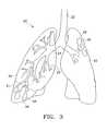
- FIG. 3is an illustration of a lung having a diseased lower portion prior to surgery
- FIG. 4is a perspective view of a plurality of anchored anchors before being pulled to compress the volume of a portion of a lung;
- FIG. 5is a top view of the plurality of anchored anchors shown in FIG. 4.
- FIG. 6is a perspective view of a plurality of anchored anchors after being pulled to decrease the compress the volume of a portion of a lung according to one embodiment of the present invention
- FIG. 7is a top view of the plurality of anchored anchors shown in FIG. 6.
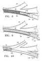
- FIG. 8is a side cross sectional view of an anchor being inserted into a bronchial passageway according to one embodiment of the present invention.
- FIG. 9is a side cross sectional view of an anchor anchored to a bronchial passageway according to one embodiment of the present invention.
- FIG. 10is a side cross sectional view of an anchor fixed to a bronchial passageway and tethered to a self-locking device according to one embodiment of the present invention
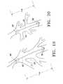
- FIG. 11is an illustration of a portion of a lung having two variations of the anchor of the present invention fixed within lung and two cords connecting the anchors;
- FIG. 12is an illustration of a portion of a, lung with anchors fixed within the lung as a delivery device is advanced into the airways to reduce the length of cord between anchors;
- FIG. 13is an illustration of a portion of a lung after its the volume has been reduced according to one embodiment of the present invention.
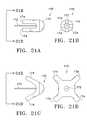
- FIG. 14is a side view of an anchor for use with the present invention.
- FIG. 15is an end view of the anchor of FIG. 14;
- FIG. 16is a side cross sectional view of an anchor according to one embodiment of the present invention, where the anchor is in a collapsed state and is located within a tube;
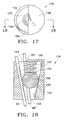
- FIG. 17is a top view of a self-locking device according to one embodiment of the present invention.
- FIG. 18is a side cross sectional view of the self-locking device of FIG. 17 taken along the line 18 — 18 of FIG. 17;
- FIG. 19is an illustration of a portion of a lung before its volume has been compressed
- FIG. 20is an illustration of the portion of the lung of FIG. 19 after its volume has been compressed
- FIGS. 21A-29illustrate variations of the anchor of the present invention
- FIGS. 30-33Billustrate variations of the delivery device of the present invention
- FIGS. 34-44illustrate variations of the connector of the present invention
- FIGS. 45A-45Billustrate a plug for use a connector of the present invention
- FIGS. 46-48illustrate variations of the cord for use with anchors of the present invention
- FIGS. 49-53illustrate variations of the cord cutter of the present invention
- FIGS. 54-56illustrate deployment of a variation of the present invention where an anchor is deformed by a tapered delivery device to assume an expanded profile and connected to another cord by means of a connector;
- FIGS. 57-58illustrate deployment of a variation of the present invention where an anchor is expanded by use of a wedge
- FIGS. 59-60illustrate deployment of a variation of the present invention where an anchor is comprised of a wire and is rotated to attach to an airway wall;
- FIGS. 61A-61Billustrate a further variation of an anchor of the present invention
- FIGS. 62A-62Billustrate a further variation of a delivery device of the present invention
- FIG. 63illustrates deployment of the anchor variation depicted in FIGS. 61A and 61B.
- FIG. 64illustrates a support member placed within a lung to increase the anchoring ability of an anchor.
- the present inventionpertains to a method and assembly to relieve the effects of emphysema and other lung diseases by increasing the efficiency of gas exchange in the lung. This is achieved by compressing the volume of a portion of the lung, preferably a diseased portion of the lung tissue. Compressing the volume of a portion of the lung redistributes the remaining lung tissue to allowing the tissue to inflate more fully. The reduction in volume of the portion of the lung also increases the range of motion of the diaphragm and chest wall thereby improving lung efficiency.
- FIG. 3illustrates human lungs 20 having a left lung 32 and a right lung 30 .
- a diseased portion 31is located at the lower portion or base of the right lung 30 (indicated by the volume of the lung below the dashed line on the right lung).
- the diseased portions of an unhealthy lungmay not be located in discrete areas.
- the trachea 22extends down from the larynx and conveys air to and from the lungs.
- the trachea 22divides into right and left main bronchi 24 , which in turn form lobar, segmental, and sub-segmental bronchi or bronchial passageways.
- the bronchial tree 23extends to the terminal bronchiole.
- alveolar sacs 26 containing alveoli 28perform gas exchange as humans inhale and exhale.
- the diseased portion 31 of the lung 30is located at the lower portion or base of the lung.
- this diseased portion 31has been stricken by emphysema.
- the emphysematous portion 31 of the lung 30generally includes sections in which the walls between the adjacent alveoli 28 have deteriorated to a degree that the lung tissue looks like Swiss cheese in cross section. When this occurs, pulmonary function is significantly impaired due to reduced total surface area of alveolar wall tissue which serves as the gas exchange mechanism of the lung. Because of emphysema, the diseased portion of the lung also contributes to the loss of it's the lung's elastic recoil properties.
- the lungalso experiences a loss in the force used to expel air during expiration.
- the present inventionstrives to relieve the effects of emphysema by increasing the lung's 30 efficiency to perform gas exchange.
- the present inventionincreases the range of motion of the diaphragm and chest wall by compressing the volume of a portion of the lung occupied in the thoracic cavity to redistribute the remaining healthier lung tissue, thus improving the efficiency of gas exchange in the lung.
- a volume of a portion of a diseased lungis compressed or reduced by locating an anchor in a bronchial passageway of the lung, and pulling on the anchor to collapse the lung tissue surrounding the anchor to compress the volume of a portion of the lung.
- a plurality of anchorsare used to assist in collapsing an area of the lung tissue.
- the anchorsmay be deployed exterior to the lung. Once anchors have been placed, they are drawn together and compress lung tissue. It is believed that the lung has an ability to seal small holes formed in the lung tissue as a result of the placement of the anchors.
- FIGS. 4-7illustrate the general concept of the present invention.
- FIGS. 4 and 5represent a time t 1
- FIGS. 6 and 7represent a later point in time t 2 .
- a plurality of anchors 38 , 38 ′, 38 ′′, 38 ′′′are located at different positions in the lung.
- the anchors 38 , 38 ′, 38 ′′, 38 ′′′are anchored, fixed, or firmly attached to the lung (not illustrated) at their respective different positions.
- the area of the lung that is immediately surrounding each anchorwill move when the respective anchor is moved.
- the anchors 38 , 38 ′, 38 ′′, 38 ′′′are equally spaced as shown in FIGS. 4 and 5. However, the anchors may be located at various positions in the lung so as to not be evenly or equally spaced and still function to compress the volume of a portion of the lung as described herein. Attached to each of the anchors 38 , 38 ′, 38 ′′, 38 ′′′ is a cord 40 , 40 ′, 40 ′′, 40 ′′′ which can be in the form of a string, fiber, filament, rubber band, coil spring, or the like.
- Each of the cords 40 , 40 ′, 40 ′′, 40 ′′′has a free end 41 , 41 ′, 41 ′′, 41 ′′′ and an attached end 43 , 43 ′, 43 ′′, 43 ′′′.
- the attached end 43 , 43 ′, 43 ′′ 43 ′′′ of each cordis that end of each respective cord 40 , 40 ′, 40 ′′, 40 ′′′ that is attached or tethered to the respective anchors 38 , 38 ′, 38 ′′, 38 ′′′.
- each cord 40 , 40 ′, 40 ′′, 40 ′′′is the furthest end of each respective cord not attached to the respective anchors 38 , 38 ′, 38 ′′, 38 ′′′.
- the anchors 38 , 38 ′, 38 ′′, 38 ′′′generally lie along the circumference of a circle C 1 .
- the anchors 38 , 38 ′, 38 ′′, 38 ′′′are illustrated as lying along the circumference of a circle, the anchors can be located in other configurations.
- the anchorscan be anchored in different planes and spaced apart from each other in a variety of different configurations.
- the circle C 1has an area A 1 .
- Each of the cords 40 , 40 ′, 40 ′′, 40 ′′′is attached to a respective anchor 38 , 38 ′, 38 ′′, 38 ′′′.
- the cord 40 ′is attached to the anchor 38 ′.
- Each of the cords 40 , 40 ′, 40 ′′, 40 ′′′is connected to a connection device 36 .
- connection device 36connects, knots, unites, bonds, fastens, glues, wedges, attaches, or fixes together the cords 40 , 40 ′, 40 ′′, 40 ′′′ such that when one of the cords 40 attached to an anchored anchor 38 is pulled in tension, the other cords 40 ′, 40 ′′, 40 ′′′ may also be placed in tension.
- the connection device 36is thus connected to the first anchor 38 by the first cord 40 and is connected to the second anchor 38 ′ by the second cord 40 ′.
- connection device 36when two cords 40 , 40 ′ are connected by the connection device 36 , the two cords 40 , 40 ′ between the two anchors 38 , 38 ′ and the connection device 36 together function as or define one cord connecting to the two anchors 38 , 38 ′.
- the connecting device 36can be a clasp, clamp, cinch, snap, knot, clip, chock, self-locking device, or the like.
- the first cord 40has a first cord length measured between the first anchor 38 and the connection device 36 .
- the second cord 40 ′has a second cord length measured between the second anchor 38 ′ and the connection device 36 .
- the other cords 40 ′′, 40 ′′′have cord lengths measured between the respective anchor and the connection device 36 .
- the connection device 36prevents each of the cord lengths from increasing, i.e., prevents the anchors from returning to their original anchored positions.
- 4-7is a self-locking device, described further below, that permits each of the cords 40 , 40 ′, 40 ′′, 40 ′′′ to traverse away from the self-locking device in a direction toward the free ends 41 , 41 ′, 41 ′′, 41 ′′′, but prevents each of the cords from traversing away from the self-locking device in a direction toward the attached ends 43 , 43 ′, 43 ′′, 43 ′′′.
- the cords 40 , 40 ′, 40 ′′, 40 ′′′pass through an opening in the self locking device.
- the cords 40 , 40 ′, 40 ′′, 40 ′′′ illustrated in FIGS. 4 and 5have been pulled taut. That is, the cords 40 , 40 ′, 40 ′′, 40 ′′′ have been pulled or drawn tight and are not slack. However, at the time t 1 illustrated in FIG. 4., the anchors, and surrounding lung tissue, have not been moved. Thus, the lung has not been compressed and the volume has not been changed. However, after the cords 40 , 40 ′, 40 ′′, 40 ′′′ are taut and the cords are pulled or further tensioned, the distance between the anchors 38 , 38 , 38 ′′, 38 ′′′ will decrease.
- the lung tissue surrounding each anchor 38 , 38 ′, 38 ′′, 38 ′′′moves with the respective anchor such that the lung tissue between each anchor and the connection device will physically collapse or compress.
- the connection performed by the connection device 36may occur while the distance between the anchors 38 , 38 ′, 38 ′′, 38 ′′′ is decreased, or after the distance between the anchors has been decreased to a desired distance.
- a self-locking deviceis moved toward the anchors 38 , 38 ′, 38 ′′, 38 ′′′ to cause the distance between the anchors to decrease, and at each point along the path of movement of the connection device a connection between the cords 40 , 40 ′, 40 ′′, 40 ′′′ is defined.
- the anchors 38 , 38 ′, 38 ′′, 38 ′′′ and surrounding lung tissuehave been moved toward each other (toward the center of the original circle C 1 ) to define a second circle C 2 having a smaller diameter than the circle C 1 .
- the anchors 38 , 38 ′, 38 ′′, 38 ′′′generally lie along the circumference of the circle C 2 . As described above, this may be achieved by pulling the anchors 38 , 38 ′, 38 ′′, 38 ′′′ toward each other via the cords 40 , 40 ′, 40 ′′, 40 ′′′.
- the anchorscan be pulled or moved toward each other by: (1) pulling the free ends 41 , 41 ′, 41 ′′, 41 ′′′ of the cords away from a connection device; (2) moving the connection device 36 toward the anchors 38 , 38 ′, 38 ′′, 38 ′′′ to pull the anchors; or (3) simultaneously moving the self-locking device toward the anchors and pulling the free ends of the cords away from the self locking device.
- connection devicemay not lie in the plane formed by the circles C 1 or C 2 . This may be the case when it is desired to compress tissue in the direction perpendicular to the plane formed by either of the circles, or to simply compress a greater volume of tissue. In this case, it may be necessary to anchor the connection device in the lung tissue so that force can be generated in the direction perpendicular to the plane formed by either circle.
- connection device 136is held in position by positioning the connection device at an airway bifurcation 27 .
- the forces exerted on the connection device 136 by the tension of the lines 40 , 40 ′, 40 ′′, 40 ′′′may be balanced about the bifurcation 27 to keep the connection device 136 in place.
- “wings” or “flaps”may be added to the connection device to prevent movement of the device from the bifurcation 27 of the airway.
- FIGS. 7C and 7Dillustrate additional variations of the invention.
- anchoring features of anchorsmay be added to the connection device so that the connection device can be anchored into a non-bifurcated section of airway.
- the anchoring featuremay be deployed into place in a similar manner as described elsewhere for deploying an anchor.
- the area of the second circleis smaller than the area of the first circle. Because the area of the second circle C 2 is smaller than that of the first circle C 1 (and the distance between the anchors 38 , 38 ′, 38 ′′, 38 ′′′ has decreased), the lung tissue near the anchors will collapse or compress inwardly toward the center of the circles C 1 , C 2 . Depending upon the location of the anchors 38 , 38 ′, 38 ′′, 38 ′′′, the anchors can move inwardly toward the center of the circles and slightly toward the center or interior of the lung.
- the net surface area or peripheral surface of the portion of the lungis less, and the volume of the lung is less due to the collapsing or compressing of the lung tissue.
- the remaining portion of the cords having the free ends 41 , 41 ′, 41 ′′, 41 ′′′may be cut such that non-functional portions of the cords may be removed from the lungs by pulling the cords out of the mouth or nasal cavity.
- FIGS. 8-10illustrate a variation of how the anchors 38 , 38 ′, are located in and fixed to the outer periphery of the bronchial tree.
- a delivery device 34is sized to fit within a bronchial passageway 25 .
- the delivery device 34is used to deliver the anchor 38 to the outer periphery of the bronchial tree and may be a cannula, tube, bronchoscope, or another device capable of accessing the outer periphery of the bronchial tree.
- the delivery device 34may be configured to house an anchor within the delivery device 34 or the device 34 may be configured to removably seat an anchor on an outside of the device 34 .
- the anchor 38 to be delivered to the outer periphery of the bronchial treemay be located inside the delivery device 34 . It is preferred that the delivery device be fed into the lungs through a bronchoscope. It is also possible for the bronchoscope to be used as the delivery device. After the proper location has been determined with the bronchoscope, the anchor 38 is delivered as described below.
- an anchormay be a V-shaped spring 138 .
- the V-shaped spring 138is in a collapsed state or reduced profile while it remains inside the tubular channel of the delivery device 34 .
- the V-shaped springexpands to an expanded position or expanded profile, as shown in FIG. 9 .
- the V-shaped spring 138expands, it is fixed or fastened to the walls of the bronchial passageway 25 such that the lung tissue in the vicinity of the V-shaped spring moves with the V-shaped spring.
- a hollow second tube or a push-device 35 having a size or diameter smaller than that of the internal diameter of the delivery device 34is inserted into the delivery device 34 to force the V-shaped spring 138 out of the delivery device 34 into the bronchial passageway 25 .
- FIGS. 14-16illustrate further details of the V-shaped spring 138 .
- the V-shaped spring 138may be a rod shaped piece that has been bent such that it has spring-like characteristics.
- the V-shaped spring 138includes an attachment portion comprising two end portions or barbs 142 that form an angle relative to a lateral or central portion 144 of the V-shaped spring when the barbs are in the extended position.
- the barbs 142together define the V-shape of the V-shaped spring when the barbs are in an expanded position.
- the barbs 142together define the point or vertex of the “V” at an insertion end 148 of the V-shaped spring.
- the barbs 142perform the anchoring function of the V-shaped spring 138 by wedging against the bronchial passageway to create friction or by penetrating the walls of the bronchial passageway. Because of the spring-like characteristics of the V-shaped spring, the barbs 142 strive to angle outwardly from the lateral portion 144 .
- the V-shaped spring 138also includes an attachment end 146 located on the lateral or central portion 144 opposite from the insertion end 148 .
- the attachment end 146is the location where one of the cords 40 is tethered.
- the barbs 142strive to extend angularly outward from the lateral portion 144 , and form an angle with respect to the lateral portion.
- the insertion end 148 of the V-shaped spring 138will be the first portion of the V-shaped spring that exits the tube 34 as the push device 35 forces the V-shaped spring from the tube.
- the attachment end 146 of the V-shaped spring 138is the last portion of the V-shaped spring to exit from the tube 34 .
- the barbs 142 of the V-shaped spring 138prevent the expanded V-shaped spring from moving in a direction opposite to the direction in which the “V” or vertex points. That is, the barbs 142 may function similarly to barbs on a fish hook, harpoon, or arrow.
- the barbs 142may each include a sharp point 143 that curves or projects in a direction opposite from the direction the vertex at the insertion end 148 points.
- the barbsmay be of any design that facilitates securing an anchor to lung tissue.
- anchoring devicesmay be used to perform the anchoring function.
- a J-hook, a mooring device, a ballooning device, and expanding polymeric plug, a stent-like device, and other various devicescan be satisfactorily fastened, fixed or anchored to the bronchial passageway of a lung.
- Other anchorsare described below.
- the V-shaped springsinclude two barbs 142
- the V-shaped springcan have more than two barbs or only one barb.
- the connection device 36itself can also anchor to the lung.
- two cords 40 , 40 ′ having anchors 38 , 38 ′ attached theretocan be tied to a third anchor such that the third anchor is a connection device.
- FIG. 16illustrates a side view of the V-shaped spring 138 in its collapsed position when the V-shaped spring is located within the tube 34 .
- the barbs 142collapse toward the lateral portion 144 when the V-shaped spring 138 is positioned within the tube 34 .
- the cord 40Prior to inserting the V-shaped spring 138 into the tube 34 , the cord 40 is secured to the attachment end 146 of the V-shaped spring.
- the cord 40can be tethered, braided, buttoned, interlocked, wired, pinned, clasped, or joined to the attachment end 146 by any suitable means.
- the cord 40may be wrapped around the attachment end 146 and secured to itself to define a loop around the attachment end 146 .
- a clasp 50 or other similar devicemay be used to secure the loop around the attachment end 146 .
- FIG. 9illustrates that the cord 40 remains attached to the V-shaped spring 138 after the push device 35 has been withdrawn from the tube 34 and after the V-shaped spring has expanded.
- the protruding ends 42 of the V-shaped spring 138extend into the walls of the bronchial passageway 25 such that the V-shaped spring 138 is fixedly secured to the bronchial passageway.
- the tube 34can be withdrawn from the bronchial passageway 25 . Thereafter, the same procedure can be followed to deposit more V-shaped springs 138 (each having a cord 40 attached thereto) in other bronchial passageways at locations distant from the area where the first V-shaped spring was positioned.
- the anchors 38 , 38 ′such as V-shaped springs, have been fixed to different positions in the bronchial tree, the cords 40 , 40 ′ can be tensioned.
- FIGS. 11-13illustrate in further detail how the diseased portion of a lung 31 may be collapsed to reduce the volume of the lung 30 .
- the bronchial tree-like pattern 23 in the lung 30includes a multitude of bronchial passageways 25 . Any of these bronchial passageways 25 may be used to insert an anchor 38 into the lung. Because the bronchial passageways 25 are hollow, it is possible to insert a delivery device 34 such as a tube, a bronchoscope, or a cannula into one bronchial passageway. As shown in FIG. 11, the lung 31 includes therein a pair of anchors 38 , 38 ′ which have been anchored or attached to two separate bronchial passageways 25 in the outer periphery of the bronchial tree 23 .
- Attached to each of the anchors 38 , 38 ′is a cord 40 , 40 ′ that extends from each of the anchors 38 , 38 ′ through the bronchial tree 23 and into the delivery device 34 .
- One cord 40 , 40 ′is tethered to each of the anchors 38 , 38 ′.
- the line or cord 40like the delivery device 34 , extends through the bronchus 24 up the trachea 22 and out the mouth or nasal cavity of the patient.
- connection devicesmay be placed in front of, outside of, or inside the distal tip of the delivery device 34
- the connection device 36is positioned to cause the cords 40 , 40 ′ to be tensioned and to move the anchors 38 , 38 ′.
- the connection device 36can be used to connect the cords 40 , 40 ′ and to cause the anchor 38 to move toward the anchor 38 ′, thereby causing the tissue adjacent the anchor 38 to move towards the lung tissue adjacent the anchor 38 ′.
- FIG. 13illustrates the compressed lung.
- the cordsmay be cut proximal to the connection device 36 , and the excess cords and delivery device may be removed from the patient.
- the connection device 136 , the anchors 38 , 38 ′, and the shortened sections of cords 40 , 40 ′ left in placemaintain the compression of the lung tissue.
- FIGS. 17 and 18illustrate one embodiment of the connection device 36 .
- the self-locking device 136is configured to permit each of the cords 40 , 40 ′ to traverse away from the self-locking device in a direction toward the free ends 41 , 41 ′.
- the connection device 136may also be configured to prevent each of the cords 40 , 40 ′ from traversing away from the self-locking device in a direction toward the attached ends 43 , 43 ′ of the cords 40 , 40 ′.
- the self-locking device 136includes a passageway or channel 155 extending through the self-locking device 136 , from a first opening 159 to a second opening 160 .
- the cords 40 , 40 ′pass through the openings 159 , 160 and hence through the channel 155 in the self-locking device 136 .
- the self-locking device 136prevents the cords 40 , 40 ′ from being pulled back toward the anchors 38 , 38 ′.
- the self-locking deviceWhen the self-locking device is located in the lung, it only permits the portion of the cords 40 , 40 ′ in the channel 155 to travel or be displaced relative to the self-locking device in a direction toward the trachea, not toward the outer periphery of the bronchial tree where the anchors 38 , 38 ′ are located.
- the self-locking device 136allows the cords 40 , 40 ′ to pass in one direction, but locks the cords in place when they are forced to move the in the other direction.
- This variation of the self-locking device 136may include a cylindrical body 152 having a tapered inner wall 154 that extends through the body 152 to define the conical channel 155 .
- the tapered inner bore 154defines a conical interior.
- a ball 156rests in the channel 155 and is retained therein by a cap or cover 158 located over the larger end of the taper.
- the cover 158preferably covers the larger end of the bore to such an extent that the area of the first opening 159 is smaller that the cross-sectional area of the ball 156 .
- the opening 159should be large enough to permit at least one line 40 to pass through the first opening.
- the first opening 159is large enough to permit two cords 40 , 40 ′ to pass there-through. Because the cover 158 does not completely cover the larger bore diameter of the conical channel 155 , the cords 40 , 40 ′ will fit through the gap or first opening 159 between the wall 154 and the edge 161 of the cover 158 . Thus, the cords 40 , 40 ′ fit through the gap 159 .
- Other embodiments of the self-locking device 136may be configured to receive more than two cords.
- the self-locking device 136is dimensioned and configured such that when a cord 40 is pushed or pulled through the smaller second opening 160 (or smaller bore), the cord 40 will displace the ball 156 toward the cap 158 just enough for the line to continuously pass through the self locking device.
- the ball 156will displace towards the smaller second opening 160 , i.e., away from the cap 158 . Because the ball 156 has a larger cross-sectional area than that of the smaller second opening 160 , the ball will wedge against the conical inner wall 155 and the cord 40 , locking, wedging, or chocking the cord in place.
- the self-locking device 136will permit the line to be pulled in this direction. However, if the line 40 is pulled in the opposite direction away from the cover 158 , the ball 156 will wedge against the line 40 and the inner wall 154 such that the line 40 cannot travel relative to the self-locking device 136 . This wedging effect occurs because of the friction between the ball 156 , the line 40 , and the wall 154 .
- the self-locking devicemay be configured with a spring 157 , such as a coil or leaf spring, that may be positioned between the cover 158 and the ball 156 to ensure that the ball is always biased towards the small opening 160 of the device.
- the self-locking device 136is configured for two cords 40 , 40 ′.
- the self-locking device 136will self-lock two cords 40 , 40 ′ and only permit the lines 40 , 40 ′ to be moved in the direction toward the cover 158 .
- the direction toward the cover 158is also the direction towards the trachea, away from the position where the self-locking device is located.
- connection device 36may include a plurality of tapered inner bores 154 and balls 156 each configured to receive and lock one line 40 , rather than two lines 40 , 40 ′.
- a connection devicemay include a plurality of tapered inner bores 154 and balls 156 each configured to receive and lock one line 40 , rather than two lines 40 , 40 ′.
- other self-locking, chocking, cleating, or wedging devicessuch as devices similar to those used on sailing and marine vessels would also perform adequately.
- clasping, clamping, or even gluing or melting the lines togethermay suffice as a connecting device 136 .
- connection device 36need not have a self-locking function.
- the connection device 36need only substantially prevent the first cord length (measured between the first anchor 38 and the connection device 36 ) and the second cord length (measured between the second anchor 38 ′ and the connection device 36 ) from increasing. This result occurs because the connection device 36 does not allow relative movement between connected cords 40 , 40 ′ with respect to the connection device when the connection device connects or fixes together the cords 40 , 40 ′.
- the connection device 36will also be forced in a state of tension or will be pulled.
- connection device 36can also function as an anchor, or the anchor 38 can function as a connection device.
- the self-locking device 136can include a plurality of barbs or hooks such that it can be anchored to a bronchial passageway or a bifurcation between two airways.
- FIGS. 10-13illustrate how the anchors 38 , 38 ′ may be used to collapse the tissue of the lung to decrease the volume of the lung.
- the anchors 38 , 38 ′may be lodged in the outer periphery or most distal part of the bronchial tree through a delivery device 34 or a standard bronchoscope inserted through the mouth or nose of the patient.
- the cords 40 , 40 ′are gathered together and the free ends 41 , 41 ′ are inserted through the connection device 36 and then into the first end 37 of the delivery device 34 , which may be the same delivery device that was used to deliver the anchors 38 , 38 ′, or a different delivery device.
- the gathered cords 40 , 40 ′are received by the delivery device 34 until the free ends 41 , 41 ′ protrude from the second end 39 of the delivery device 34 .
- the first end 37 of the delivery device 34 along with the connection device 36is then inserted into the trachea and into the bronchial tree towards the lodged anchors 38 , 38 ′.
- FIG. 11illustrates the delivery device 34 first entering the bronchial tree.
- FIG. 12illustrates the delivery device 34 positioned farther into the bronchial tree towards the anchors 38 , 38 ′.
- the free ends 41 , 41 ′are preferably prevented from entering the lung while the delivery device 34 is being inserted into the lung with the cords 40 , 40 ′ therein.
- the lunghas not been collapsed and is in its original position A.
- the anchor distance L ADthe anchor distance between the first anchor 38 and the second anchor 38 ′
- connection device 36connects the cords 40 , 40 ′ such that the reduced anchor distance L AD is maintained.
- the cords 40 , 40 ′will remain in tension due to the elastic properties of the lung.
- FIG. 13the lung tissue has been partially collapsed or compressed to the new position B from the original position A.
- the volume of a portion of the lunghas been compressed or decreased in accordance with one embodiment of the present invention.
- the delivery device 34can be used to locate or position the connection device 36 into the interior of the lung along the bronchial tree toward the anchors 38 , 38 ′; this can occur before, during, or after the anchor distance L AD has been decreased.
- the connection device 36connects the cords such that the anchor distance L AD is maintained and the lung volume remains reduced. Thereafter, the portions of the cords 40 , 40 ′ between the connection device 36 and the free ends 41 , 41 ′ are cut or broken from the tensioned portions of the cords 40 , 40 ′ that maintain the reduced anchor distance LAD.
- the cut portion of the cords 40 , 40 ′ having the free ends 41 , 41 ′is removed from the reduced volume lung.
- the delivery device 34is also removed from the reduced volume lung.
- the cords 40 , 40 ′can be cut by a variety of techniques well known in the art.
- the anchors 38 , 38 ′, spaced from each other by the reduced anchor distance L AD , and the tensioned cords 40 , 40 ′remain in the reduced volume lung, preferably for the life of the patient.
- FIG. 10illustrates how the preferred self-locking device 136 connects cords 40 , 40 ′ together.
- a second anchor 38 ′has been secured to the bronchial passageway at a place distant from that where the first anchor 38 is positioned.
- the second line 40 ′is attached to the second anchor 38 ′.
- the delivery device 34may be used to force the self-locking device 136 towards the anchors 38 , 38 ′ to pull the anchors via the cords 40 , 40 ′.
- the self locking device 136may also be released from the inside of the delivery device 34 , or from the working channel of a standard bronchoscope. Because the free ends 41 . 41 ′ of the cords 40 , 40 ′ are held taut, as the self-locking device 136 is moved toward the anchors 38 , 38 ′, the cords 40 , 40 ′ move relative to the self-locking device. As the self-locking device 136 is moved closer and closer to the anchors 38 , 38 , the cords 40 , 40 ′ can be pulled or further tensioned to reduce the anchor distance L AD .
- the self-locking device or chock device 136cinches-up on the cords 40 , 40 ′ and holds them in place while they are pulled and/or while the self-locking device is pushed toward the anchors. Because the self-locking device 136 automatically prevents the cords 40 , 40 ′ from reversing direction back toward the anchors 38 , 38 ′, once the desired reduced anchor distance L AD is obtained, the self-locking device 136 automatically connects the cords 40 , 40 ′ to each other such that the reduced anchor distance L AD is maintained. Thus, there is no need to manually connect the cords 40 , 40 ′ to each other with a clasp or other connecting device 36 . The more the anchors 38 , 38 ′ are pulled toward the self-locking device 136 (generally located at the median between the anchors) via the lines 40 , 40 ′, the more the lung tissue will collapse inward.
- anchors 38can be used to further collapse or compress the volume of a portion of the lung.
- three anchorsmay be spaced approximately 120 degrees apart from each other such that the anchors 38 each tension an equal portion of the area to be collapsed. In this manner, a larger portion of the lung may be collapsed, thus reducing the volume of the lung to a greater extent.
- the distance between two anchors 38 , 38 ′can be decreased by pulling or tensioning one cord 40 , rather than two cords.
- the first anchor 38can be anchored or fixed at a first location and a second anchor 38 ′ is fixed or located at a second location.
- the first anchor 38 and the second anchor 38 ′are separated by an original distance L OD .
- the cord 40is attached to the anchor 38 before it has bee n anchored.
- the cord 40can be attached to the first anchor 38 after the anchor 38 has been anchored at the first position.
- the cord 40is slack or limp, and the anchors 38 , 38 ′ are in their original positions.
- the cord 40is pulled to decrease the distance between the anchors 38 , 38 ′ or move one anchor 38 toward the other anchor 38 ′.
- the cord 40is placed in tension to pull the anchor 38 toward the anchor 38 ′ to defined the anchor distance L AD which is less than the original distance L OD .
- the tensioned cord 40can be attached to the second anchor 38 ′ such that the distance between the first anchor 38 and the second anchor 38 ′ is not permitted to return to the original distance.
- the remaining non-functional portion of the cord 40has been removed by cutting the cord 40 at a location directly adjacent to the anchor 38 and then pulling the excess cord from the lung.
- the second anchor 38 ′is a self-locking device, such as that shown in FIGS. 17 and 18, but has barbs or hooks such that it also is an anchor.
- the distance between the two anchored anchors 38 , 38 ′can be reduced by pulling one cord 40 to compress the volume of a portion of the lung.
- the cordscan be an elastic device that regains its original shape after compression or extension, such as a coil of wire that keeps anchors attached thereto under constant tension.
- the cordcan provide a constant or discontinuous tensile force to the anchors.
- the cordcan be an elastic filament such as a rubber band, or a expandable spring.
- connection device 36 , 136 and its components, the anchor 38 , 138 , and the line 40may be made from a chemically inert and biocompatible, natural, or synthetic material which is well known in the art.
- materialis preferably a non-bioerodable material which will remain in the patient after use, such as titanium or a titanium alloy.
- preferred materialsare those acceptable for human implants.
- typical materials of construction suitable for the above-mentioned itemsinclude non-reactive polymers or biocompatible metals or alloys.
- Metallic materials usefulinclude stainless steel, platinum, tantalum, gold, and their-alloys, as well as gold-plated ferrous alloys, platinum-plated ferrous alloys, cobalt-chromium alloys, nickel titanium alloys, and titanium nitride coated stainless steel.
- the cablescan be made from nylon, and the anchors can be made from a titanium alloy.
- the cablescan be made from elastic materials such as an elastomer that is stretchable like a rubber band.
- FIGS. 21A-29illustrate further variations of an anchor of the present invention. It is intended that the drawings not limit the physical attributes of the anchors illustrated. For example, it is contemplated that the anchors may have more or less tines than shown by the drawings. Moreover, the ends of the attachment portion may be selected to be atraumatic to the walls of the airway or may be selected to penetrate the walls of an airway.
- One variation of the anchorincludes anchors that are sized to enter airways of less than 3 mm in approximate diameter.
- FIG. 21Aillustrates an anchor 170 having a central portion 176 and an attachment portion 174 .
- the attachment portion 174 of the anchor 170is in a reduced profile. This profile is preferably sized such that the anchor 170 may be advanced through airways of the lung.
- the anchor 170may additionally have a cord 172 extending from the central portion 176 .
- FIG. 21Bis a rear view of FIG. 21A taken along the line 21 B in FIG. 21 A.
- the anchor 170is illustrated to have four tines 174 which comprise the attachment portion. However, it is contemplated that the number of tines 174 may vary as desired or needed.
- FIG. 21Cillustrates the anchor 170 of FIG.
- the expanded profileis sized such that the anchor 170 will attach to a wall of an airway or other lung tissue.
- the attachment portion 174 of the anchor 170may provide a frictional hold against the airway walls which may include a deformation of the airway walls or the attachment portion 174 may penetrate the airway walls.
- FIG. 21Dis a rear view of FIG. 21C taken along the line 21 D.
- the attachment portion 174 of the anchor 170may be mechanically deformable to attain the expanded profile, or it may be restrained into the reduced profile whereupon the removal of the restraint causes the attachment portion 174 to expand into the expanded profile.
- a shape memory alloywhich allows the attachment portion 174 to assume the expanded profile by a change in temperature.
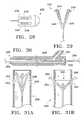
- FIGS. 22A-22Billustrate another variation of an anchor 180 .
- the anchoris shown to have an attachment portion comprising two tines 184 .
- the tinesextend from the central portion 186 to which the cord 182 is attached.
- the anchor 180is in a reduced profile.
- FIG. 22Billustrates the tines 184 of the anchor 180 in an expanded profile.
- the tines 184may assume an expanded profile through mechanical deformation.
- the tines 184may be restrained in a reduced profile whereupon removal of the restrain causes the tines 184 to self-assume the expanded profile.
- FIGS. 23A-23Billustrate another variation of an anchor 190 .
- the anchor 190may comprise a wire having a central portion 196 and ends which comprise the attachment portion or tines 194 .
- a cord 192may be attached to the central portion 196 .
- FIG. 23Aillustrates the anchor having a reduced profile as measured by a width 198 comprising the distance from the tines to the central portion. This width 198 is preferably selected such that the anchor 190 may be advanced into an airway of a lung using a delivery device of some kind.
- FIG. 23Billustrates the anchor 190 having been rotated such that a width 199 is larger than the width 198 .
- the anchor 190may be rotated by placing the cord 192 in tension within an airway wall. It is contemplated that rotation of the anchor 190 in an airway causes the tines 194 of the anchor to attach to the walls of the airway.
- FIGS. 24A-24Billustrate another variation of an anchor 200 .
- the anchormay have a covering 208 having a wall with openings 209 .
- the anchor 200has a central portion 206 and an attachment portion or tines 204 .
- the tines 204 of the anchor 200are in a reduced profile.
- FIG. 24Billustrates the anchor 200 with the tines 204 in an expanded profile.
- the tines 204 of the anchor 200may be moved into the expanded profile by moving the cord 202 in a direction away from the anchor 200 as illustrated by the arrow in FIG. 24 B.
- FIGS. 25A-25Billustrates yet another variation of an anchor 210 having a central portion 216 and an attachment portion or tines 214 and a cord 212 attached to the central portion.
- FIG. 25Aillustrates the anchor 210 in a reduced profile while FIG. 25B illustrates the anchor 210 with the tines 214 in an expanded profile.
- FIGS. 26A-26Billustrates another variation of an anchor 200 wherein a cord 222 has a wedge 228 that may be attached at a distal end of the cord 222 .
- FIG. 26Aillustrates the anchor 220 where the tines 224 are in a reduced profile as the wedge 228 is at an end of the anchor 220 .
- FIG. 26Billustrates the wedge 228 as having been moved towards a central portion 226 of the anchor wherein the wedge 228 forces the tines 224 to assume an expanded profile.
- the anchor 220may have stops 229 to retain the wedge 228 as illustrated in FIG. 26 B.
- FIGS. 27A-27Billustrates another variation of an anchor 230 .
- FIG. 27Ashows the anchor 230 as having a body comprising a flat spring 232 .
- the anchorhas attachment portion or tines 234 extending away from the body 232 .
- FIG. 27Bshows a side view of the anchor 230 as taken along the line 27 B in FIG. 27 A.
- FIGS. 28-29are intended to illustrate anchors 236 , 242 having a fibrosing agent 240 , 244 placed in proximity to the tines 238 , 245 .
- the fibrosing agentis intended to be an irritant that induces fibrosis of tissue that assists the anchor in adhering to the lung. Also, the fibrosing agent may strengthen the tissue surrounding the anchor thus preventing the anchor from tearing the tissue.
- An example of a fibrosing agentis powdered talc or a slurry composed of powdered talc and water or saline.
- fibrosing agentscan be composed of any biocompatible agent that at least produces a degree of tissue irritation.
- the fibrosing agentmay be applied to an anchor by any process, including but not limited to, brushing, dipping, spraying, coating or a combination thereof.
- FIG. 28illustrates the fibrosing agent 240 as a solid form, however, the agent may also be powdered. The agent may be in a solid form that is crushed into a powder as the anchor assumes an expanded profile.
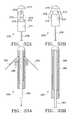
- FIG. 30illustrates a variation of a delivery device 246 used for placing an anchor at a site within the lungs.
- the delivery device 246has a lumen 256 extending through the device 246 and a seal 252 at within the lumen 256 .
- the delivery device 246also has a fluid delivery port 254 for allowing fluid to be delivered through the device 246 .
- the port 254may have a luer fitting to facilitate joining the port 254 with a source of the fluid.
- the seal 252preferably allows the cord 250 to exit from the proximal end of the delivery device 246 .
- One intended use for the deviceis to deliver a fibrosing liquid or slurry through the device 246 to a site at which an anchor is located within the lungs.
- the fibrosing liquidis intended to be an irritant that produces fibrosis of tissue at the site of the anchor. The production of the fibrotic tissue assists the anchor in remaining at the desired position and anchored to the desired tissue in the lung.
- FIGS. 31A-31Billustrate another variation of a delivery device 260 .
- the delivery device 260has openings 264 which permit the anchor 262 to expand out of the delivery device 260 .
- tines 266 of the anchor 262extend through the openings 264 of the delivery device 260 as the tines 266 expand to assume an expanded profile.
- FIGS. 32A-32Billustrate another variation of a delivery device 270 .
- FIG. 32Ashows the delivery device 270 with an anchor 273 removably seated on a tapered section 272 .
- a cord 278extends from the anchor 273 through the body of the device 271 and out of the proximal end of the device. By extending out of the device 270 , the cord 278 may be pulled in a proximal direction to allow the tines 274 of the anchor 273 to expand.
- FIG. 32Billustrates the expansion of the tines 274 to assume an expanded profile as the tines 274 are mechanically deformed by the tapered section 272 of the delivery device 270 .
- the delivery devicemay also have a guide section 276 which directs the anchor 273 as it is pulled over the tapered section 272 .
- FIGS. 33A-33Billustrate another variation of a delivery device 280 .
- the delivery device 280has a compressible sleeve 286 in contact with the tines 282 of the anchor.
- the compressible sleeve 286expands in diameter forcing the tines 282 to assume an expanded profile.
- FIGS. 34A-44illustrate variations of the connection device (hereafter variously referred to as connector, connection device, or self-locking device) for use with this invention. It is intended that the drawings not limit the physical attributes of the illustrated connectors.
- the connectorsmay be used with any number of cords.
- the bodies of the connectorsmay be rigid or elastic as required.
- the connectorsserve to connect multiple anchors having cords. Therefore, as the cords are placed within the lungs and are adjusted to compress the lung tissue, the connectors shall prevent movement of the cord to prevent maintain compression of the lung tissue.
- FIGS. 34A-34Billustrate cross sections of variations of a connector 300 .
- the connector 300comprises a simple body 304 having a passageway 302 .
- the connector 300may be cylindrical or non-cylindrical cross section.
- a connector 300may comprise the body 304 with a reduced diameter 306 of the passageway 302 .
- the reduced diameter 306may be obtained by crimping or bending the body 306 of the connector 300 .
- the reduced diameter 306provides a stop that prevents movement of a cord of an anchor (not shown) after the cord (not shown) is advanced to a desired location.
- FIG. 35illustrates a cross section of another variation of a connector 310 .
- the connectorhas body 312 having a passageway 313 , and a plug 316 which seats into a ring 314 .
- a cord(not shown) is inserted into the body 312 of the connector 310 through the passageway 313 and through the ring 314 . Insertion of the plug 316 into the ring 314 prevents movement of the cord (not shown.)
- the plug 316may be formed of a resilient material and the ring 314 may be formed from a rigid material to allow for secure placement within the ring 314 .
- FIGS. 36A-36Billustrates cross sections of a variation of the connector 320 having a plurality of stops 324 within a body 326 of the connector.
- FIG. 36Aillustrates a variation of the invention in which, the connector 320 includes a tube 322 inserted through the passageway. A cord (not shown) is inserted through the tube 324 . Upon movement of the cord to a desired position, the tube 322 is removed from the connector body 326 which permits the stops 324 to provide frictional resistance against the cord (not shown) thereby preventing movement of the cord.
- the body 326 of the connector 320may be elastic to provide an additional force against the stops to provide additional frictional forces which prevent movement of the cords.
- FIG. 36Billustrates the connector 320 of FIG. 36A in which the tube (not shown) is removed leaving a cord 323 within the connector 320 .
- the stops 324provide resistance sufficient to prevent the cord 323 from moving.
- FIG. 37Aillustrates cross section of a variation of a connector 330 having a body 338 with a passageway 336 extending through the body 338 .
- This variation of the connectoralso has a moveable section 332 within the body 338 .
- the moveable section 332has a hole 331 that may be aligned with the passageway 336 thereby allowing the placement of a cord (not shown) through the passageway 336 .
- the stop of the connectorcomprises the moveable section 332 .
- the moveable sectionmay be, but is not necessarily, spring biased to assume a nonaligned position with the passageway 336 .
- FIG. 37Bshows a cross section of a variation of the connector 330 of FIG. 37 A.
- a tube 339is used to keep the moveable section 332 in alignment with the passageway 336 .
- a cord(not shown) is placed through the tube 339 .
- the tube 339is removed allowing the moveable section 332 to hold the cord (not shown) within the connector 330 .
- FIG. 38illustrates a cross section of another variation of a connector 340 .
- the connectorhas a body 344 with a passageway 349 having a reduced diameter 346 .
- a stop in the form of a plug 342is inserted into the section of reduced diameter 346 for providing resistance against a cord 348 to prevent movement of the cord 348 .
- the plug 342is depicted as being spherical it is not limited as such.
- the plug 342may be rectangular or wedge-like with the purpose of fitting within the reduced diameter section 346 of the connector 340 .
- the reduced section of the connectormay be configured to mate with the particular design of the stop.
- Another variation of the connectorincludes a single connector body having multiple passageways each with reduced diameters and having multiple stops within the passageways. This variation allows several anchors to be joined together but only one cord per passageway.
- a preferred variation of this inventionis having six passageways, each of which has a plug.
- FIG. 39depicts a cross section of another variation of a connector 350 comprising a body 354 having a passageway 356 with a plurality of prongs, flaps, or fingers 352 extending away from the body 354 towards the center of the passageway 356 .
- the prongs 352may be used to prevent the movement of a cord having a hook or loop at a proximal end of the chord (not shown).
- the prongsmay be comprised of a resilient material or they may be fabricated to allow flexing.
- the prongsmay be angled towards an open end of the connector. In such a variation, when a cord is drawn through the connector in the direction of the angled prongs, the cord will slide freely. When the cord is moved in the opposite direction, the angle of the prongs and the frictional forces between the cord and the tip of the prongs causes the tips of the prongs to wedge into the side of the cord and prevent the cord from sliding in the opposite direction.
- FIG. 40Aillustrates a cross section of a connector 360 having a stopper 364 located within a passageway 369 of the connector 360 .
- the passageway 369allows for passage of a cord 370 through the connector 360 with the stopper 364 preventing movement of the cord 370 .
- the stopper 364may be comprised of an elastomeric material or may be a rigid material.
- the stopper 364may be attached to a body 362 of the connector 360 by a spring element 366 .
- the spring element 366may comprise an elastomeric material, such as the case where the stopper 364 and the spring element 366 are a continuous piece. Or, the spring element 366 may comprise a coiled or other type of spring.
- FIG. 40Billustrates the connector 360 of FIG.
- FIGS. 40A and 40Billustrate the stopper 364 on the connector 360 as having a plug 368 .
- the plug 368may be used to pull the stopper 364 out of the passageway 369 after the cord has been attached to the connector 360 . This feature allows one to release the cords from the connector 360 .
- FIG. 41illustrates another variation of a connector 372 having a stopper 374 attached to a base 376 of the connector 372 .
- the base 376serves as a spring element for the connector 372 .
- the connectorcomprise an adhesive to join multiple cords together.
- the cordsmay also be simply tied together.
- FIGS. 42A-42Billustrate cross sectional views of a connector having a passageway 386 with a spring 382 having a plurality of turns through which a cord 384 is woven. As illustrated in FIG. 42A the spring 382 is stretched to permit movement of the cord. FIG. 42B illustrates the spring 382 returning to its natural state whereby compression of the turns of the spring 382 prevents movement of the cord 384 .
- FIG. 43Aillustrates a cross sectional view of a connector 390 having a body 396 having a passageway 391 with a flange 392 having a central opening 394 with a plurality of slots 399 extending from the central opening.
- a cord 398 having a section of increased diameteris pulled through the central opening 394 and nested in a slot 399 .
- FIG. 43Billustrates the nesting of a cord 398 in a slot 399 in the connector 390 .
- FIG. 44illustrates another variation of a connector 400 having a body 406 having a passageway 404 with a section of reduced diameter 401 in which may be seated a plug 402 .
- a cord(not shown) may be inserted through the passageway 404 and through the section of reduced diameter 401 , wherein movement of the cord is prevented by insertion of the plug 402 into the section of reduced diameter 401 .
- FIG. 45Aillustrates a side view of a plug 402 .
- FIG. 45Billustrates a top view of the plug 402 .
- the plugmay have a slot 408 which assists in insertion of the plug 402 into the section of reduced diameter 401 .
- FIG. 44illustrates the connector as having three plugs 402 and three sections of reduced diameter, the connector 400 is not limited as such.
- the connector 400may have up to six plugs and six sections of reduced diameter for insertion and retention of six chords.
- FIG. 46illustrates a variation of an anchor device 410 .
- the anchor device 410has a central portion 412 an attachment portion 414 and a cord 418 that may extend from the central portion 412 .
- This variation of the anchor 410has a cord 418 which has segments 416 of increased diameter. Although these segments 416 are depicted as being spherical they are not limited as such and may be of any shape so long as they have a greater dimension than the cord.
- the segments 416may be adjustable on the cord 418 thereby allowing effective adjustment of the length from the placement site of the anchor in the lung to a connector.
- This variation of the anchor device 410may be used with a simple tubular connector (not shown) with another similar anchor device wherein the anchor devices are placed in tension in opposite directions and the sections of increased diameter provide interference within the tube preventing movement of the cords.
- FIG. 47illustrates a variation of a cord 420 for use with the invention.
- the cord 420comprises a tube 422 having a lumen 424 .
- the tube 422may be elastic.
- the lumen 424allows for assisting in ventilation of air between portions of the lungs that are compressed by the assembly of the invention described herein.
- the chord 420may have openings 426 in the lumens to assist in the transportation of air.
- the use of an elastic tubemay further assist in collapsing or reducing the section of lung between the anchors.
- FIG. 48illustrates another variation of an anchor device 430 with the cord 436 having a hook 438 at a proximal end of the cord 438 .
- the hook 438may simply attach to an end of a tubular connector (not shown). It is also contemplated that instead of the hook 438 , the cord may have a loop or ring so that the cord may be secured to a connector.
- FIG. 48also illustrates a variation of the invention in which the anchor 432 is attached to a hook 438 via an elastic cord 436 . In such a case, the hook 438 may adhere to a portion of the lung and the anchor may adhere to a second distant portion by stretching of the cord 436 . The anchor 432 will be drawn towards the hook 438 as the cord 436 returns to its relaxed state.
- This variation of the anchoring device 430may eliminate the need for a connector (not shown).
- FIGS. 49-53illustrate variations of cutters for use with the invention described herein.
- the cutterstrim the excess cord after the anchor is set and the cords are pulled to collapse the volume of lung tissue.
- FIG. 49illustrates a variation of a cutter 440 having an elongate member 443 having a first shearing surface 442 and a second shearing surface 444 within the elongate member 442 . As the first shearing surface 442 and the second shearing surface meet, the cord 446 is cut.
- FIG. 50shows a cross section of a variation of a cutter 450 where a shearing surface 452 cuts a cord 446 as it joins a second shearing surface 454 .
- FIG. 51illustrates another variation of a cutter 460 , in this variation an elongate member 463 has a first shearing surface 462 while a second shearing surface 464 is moveable within the elongate member 463 .
- the second shearing surface 464may be axially moveable within the elongate member or torsionally moveable or a combination thereof.
- FIG. 52illustrates a variation of a cutter 470 wherein a cutter 472 extends into a passageway 471 of a delivery device 473 to cut a cord 446 .
- the cuttermay be a blade, a heating element, or a flexible rod having a sharpened end.
- FIG. 53illustrates a variation of a cutter 474 where the cutter 474 is a suture cutter 474 having a cutting surface 476 .
- FIGS. 54-60illustrate variations of the invention described herein as used in an airway within a lung. As described above, the invention may also be attached to the exterior of the lung to compress the lung tissue from outside.
- FIG. 54illustrates a delivery device 480 having a tapered portion with an anchor 482 removably seated on an exterior of the delivery device 480 .
- the inventionmay include a sheath or tube 484 to access the airway.
- the inventionalso contemplates the use of a delivery device without a sheath or tube.
- the delivery device 480 of FIG. 54may be advanced into position inside an airway 25 of the lungs or to a point on the outside of the lungs without the outer tube or sheath 484 .
- the anchor 482will be mounted on the top of the delivery device 480 rather than inside a sheath 484 .
- FIG. 55illustrates the expansion of the anchor 482 as a cord 486 pulls the anchor 482 over the tapered portion of the delivery device 480 .
- the anchor 482attaches to the walls of the airway.
- the anchor 482may be configured such that the anchor penetrates the airway walls or the anchor may be atraumatic and provide resistance against the walls thereby preventing movement of the anchor 482 as tension is applied to the cord 486 .
- FIG. 56illustrates the use of a connector 490 that joins multiple cords 486 and 488 . It is contemplated that two anchors may be used on either end of a cord thereby eliminating the need for the connection device 490 . Also, the connection device may be any of the connection devices described herein.
- FIG. 57illustrates another variation of the invention described herein.
- an anchor 496is advanced to a target site via a delivery device 494 .
- FIG. 58illustrates the expansion of the anchor 496 as a cord 498 is pulled in a proximal direction causing the anchor 496 to expand.
- FIG. 59illustrates another variation of the invention using a wire anchor 500 .
- FIG. 60illustrates advancement of the anchor 500 to the site and movement of a cord 506 in a proximal direction which rotates the anchor 500 for placement in the walls of the airway.
- the anchor 500may be, for example, advanced out of the delivery device 504 by use of a push tube or wire 502 .
- the delivery device 504 along with the anchor 500may be placed at a desired location and then the delivery device 504 may be withdrawn while the push tube or wire 502 keeps the anchor 500 at the target location. In this case, the push tube or wire 502 must be of sufficient stiffness to maintain the position of the anchor 500 .
- FIGS. 61A-61Billustrate a further variation of an anchor device 510 .
- This variation of the anchor device 510comprises a central portion 516 with attachment portions 512 , 514 .
- a cord 518may be attached to the central portion 516 of the anchor device 510 .
- FIG. 61Aillustrates the anchor device having a reduced profile as measured by a width 520 comprising the shortest distance measured from either side of the anchor device 510 . In this profile the anchor device 510 may be advanced through an airway of the lungs.
- FIG. 61Billustrates the anchor device 510 once rotated to assume an expanded profile as measured by a width 522 . This width 522 is sufficiently larger than the width 520 such that the anchor device 510 may be anchored within the lung or with an airway within the lung.
- the anchor device 510may be rotated by placing the cord 518 in tension once the anchor device 510 is deployed.
- the anchor device 510 illustrated in FIGS. 61A-61Bis shown to have a sharpened attachment portion 512 and a blunt attachment portion 514 . It is contemplated that either attachment portion may be blunt or sharpened.
- the configuration of the attachment portionis selected to facilitate placement of the anchor device 510 in lung or airway tissue.
- FIGS. 62A-62Billustrate variations of deployment devices 524 , 526 used deploy an anchor.
- FIG. 62Aillustrates a delivery device 524 which deploys an anchor device 510 in an orientation that allows the anchor device 510 to be advanced through the lungs to a target site.
- FIG. 62Billustrates another device 526 which deploys an anchor device 510 in a significantly reduced profile.
- FIG. 63illustrates a possible deployment position of the anchor device 510 of FIGS. 61A-61B.
- the anchor device 510may have an attachment portion 512 that punctures a wall of the airway or other lung tissue and an attachment portion 514 that is relatively atraumatic to lung tissue.
- the anchor devicemay be configured such that both attachment portions are either sharpened or blunt.
- FIG. 64illustrates another variation of the invention where a support member 530 is placed within the lung, for example, an airway of the lung.
- the support member 530creates an area of improved anchor support for increasing the anchoring ability of any of the anchors described herein.
- the support member 530may be placed within the lung in an area that is intended to be compressed prior to placement of the anchor.
- the support member 510may then be left in the lung for a period of time to allow fibrosis of tissue over the support member 530 to assist in retaining the support member 530 within the lung.
- the support membermay also be used with a tissue irritant or fibrosing agent as described herein or any other substance that facilitates placement of the support member 530 at a desired location.
- the support member 530may be constructed of a mesh, woven, or solid design.
- the support member 530may be expandable or a tube or any other design that facilitates placement within the lung.
- FIG. 64depicts the support member 530 as a tubular structure, it may be of another shape such as a ring or other non-circular shape.
- the inventionfurther includes the method of minimally invasively or non-invasively treating a lung having at least an emphysematous portion comprising the step of improving a pulmonary function of at least a first portion of the lung.
- the step of improving a pulmonary functionmay comprise reducing hyperinflation of a second portion of the lung, increasing the range of motion of the diaphragm, redirecting airflow to a healthier portion of the lung, and/or reducing a volume of a second portion of the lung to remove non-functional residual air from the lung.
- the step of improving a pulmonary functionmay comprise attaching a first anchor to the lung, attaching a second anchor to the lung, connecting a cord between the second anchor and the first anchor, and shortening the length of the cord between the first and second anchors to compress a second portion of the lung.
- the methodmay include the use of a connector to join the first and second anchors.
- the method of improving a pulmonary functionmay also include the step of deflating the lung or the diseased portion of the lung prior to the shortening step. Deflating the lung may allow a more controlled adjustment of the connections between the lines and connecting device since less force will be exerted by the expanded lung section.
- the method of improving a pulmonary functionmay also include injecting a sclerosant agent into the second portion of the lung to maintain compression of the second portion.
- a sclerosant agentis powdered talc or a slurry composed of powdered talc and water or saline.
- sclerosant agentscan be composed of any biocompatible agent that also produces a degree of tissue irritation.
- a common use of sclerosant agentsis to encourage the formation of adhesions between the outer wall of the pleura and the chest cavity during lung surgery.
- sclerosant agentswill form adhesions between the inner walls of the diseased portion of lung that has been compressed by the invention disclosed herein, further encouraging the compressed section to remain compressed over time.
- the inventionalso includes a lung volume reduction apparatus kit comprising at least one anchor having a reduced profile and configured to assume an expanded profile wherein in the expanded profile the anchor secures to the lung and in the reduced profile the anchor is capable of being advanced in an airway of a lung, at least one connector, at least one cord having a proximal end and a distal end, the proximal end being attached to at least one of the connectors and the distal end being attached to at least one of the anchors, and a delivery device being configured to removably nest at least one of the anchors on a distal end.
- the inventionfurther includes a kit comprising the apparatus previously described and a bronchoscope.
- the kitmay also include a fibrosing and/or sclerosant agent.
- the inventionfurther includes the step of preparing the lung volume reduction apparatus described above for use in a medical procedure comprising the steps of sterilizing the lung volume reduction apparatus and packaging the lung volume reduction apparatus.
- the inventionalso includes a modified lung having an artificially compressed portion being compressed by at least two anchors secured in at least two discrete attachment areas of the lung and joined by at least one cord, wherein the anchors compress the area between the discrete attachment areas.
- the inventionalso includes the method of teaching the use of any of the devices or methods described herein.
- the network of alveoli in lungsprovides strength to the airway walls, as well as elasticity to the lungs, both of which contribute to the lung's ability to function effectively.
- lung tissueis destroyed, reducing the strength of the airways. This reduction and strength of the airway walls allows the walls to become “floppy” thereby losing their ability to remain open during exhalation.
- the patientsuffers from the inability to get the air out of their lungs due to the collapse of the airways during exhalation.
- Heavily diseased areas of the lungbecome overinflated. Within the confines of the chest cavity, this overinflation restricts the in-flow of fresh air and the proper function of healthier tissue, resulting in significant breathlessness.
- the present inventionstrives to address the above problems of overinflated and inefficient lung tissue in patients by compressing the volume of a severely diseased area of the lung, allowing the remaining healthier tissue to function more efficiently and improve patient breathing. Because the diseased portion of the lung has been collapsed or compressed, the remaining healthy tissue is redistributed, improving air exchange.
- a plurality of anchorsare lodged in the lung near the most distal part of the bronchial passageways of the lung. The anchors are drawn towards one another to cause the lung to collapse, thus compressing the airflow tissue in the lung and establishing a permanent reduction in lung volume. All of this is accomplished by a technique that is not nearly as invasive as prior art techniques for addressing this problem.
- the technique performed by the present inventioncan be performed without making a single incision. Accordingly, the risk of serious post-operative complications is greatly reduced.
Landscapes
- Health & Medical Sciences (AREA)
- Life Sciences & Earth Sciences (AREA)
- Surgery (AREA)
- Molecular Biology (AREA)
- General Health & Medical Sciences (AREA)
- Biomedical Technology (AREA)
- Heart & Thoracic Surgery (AREA)
- Medical Informatics (AREA)
- Nuclear Medicine, Radiotherapy & Molecular Imaging (AREA)
- Animal Behavior & Ethology (AREA)
- Engineering & Computer Science (AREA)
- Public Health (AREA)
- Veterinary Medicine (AREA)
- Reproductive Health (AREA)
- Vascular Medicine (AREA)
- Rheumatology (AREA)
- Surgical Instruments (AREA)
- Prostheses (AREA)
Abstract
Description
Claims (72)
Priority Applications (4)
| Application Number | Priority Date | Filing Date | Title |
|---|---|---|---|
| US09/576,786US6599311B1 (en) | 1998-06-05 | 2000-05-23 | Method and assembly for lung volume reduction |
| PCT/US2001/016888WO2001089366A2 (en) | 2000-05-23 | 2001-05-23 | Method and assembly for lung volume reduction |
| AU2001274944AAU2001274944A1 (en) | 2000-05-23 | 2001-05-23 | Method and assembly for lung volume reduction |
| US10/628,971US6997189B2 (en) | 1998-06-05 | 2003-07-28 | Method for lung volume reduction |
Applications Claiming Priority (3)
| Application Number | Priority Date | Filing Date | Title |
|---|---|---|---|
| US09/092,727US6174323B1 (en) | 1998-06-05 | 1998-06-05 | Method and assembly for lung volume reduction |
| PCT/US2000/002238WO2001054585A1 (en) | 1998-06-05 | 2000-01-26 | Method and assembly for lung volume reduction |
| US09/576,786US6599311B1 (en) | 1998-06-05 | 2000-05-23 | Method and assembly for lung volume reduction |
Related Parent Applications (2)
| Application Number | Title | Priority Date | Filing Date |
|---|---|---|---|
| US09/092,727Continuation-In-PartUS6174323B1 (en) | 1998-06-05 | 1998-06-05 | Method and assembly for lung volume reduction |
| US09/092,727ContinuationUS6174323B1 (en) | 1998-06-05 | 1998-06-05 | Method and assembly for lung volume reduction |
Related Child Applications (1)
| Application Number | Title | Priority Date | Filing Date |
|---|---|---|---|
| US10/628,971Continuation-In-PartUS6997189B2 (en) | 1998-06-05 | 2003-07-28 | Method for lung volume reduction |
Publications (1)
| Publication Number | Publication Date |
|---|---|
| US6599311B1true US6599311B1 (en) | 2003-07-29 |
Family
ID=24305977
Family Applications (1)
| Application Number | Title | Priority Date | Filing Date |
|---|---|---|---|
| US09/576,786Expired - LifetimeUS6599311B1 (en) | 1998-06-05 | 2000-05-23 | Method and assembly for lung volume reduction |
Country Status (3)
| Country | Link |
|---|---|
| US (1) | US6599311B1 (en) |
| AU (1) | AU2001274944A1 (en) |
| WO (1) | WO2001089366A2 (en) |
Cited By (315)
| Publication number | Priority date | Publication date | Assignee | Title |
|---|---|---|---|---|
| US20020198544A1 (en)* | 2001-06-22 | 2002-12-26 | Renan Uflacker | Percutaneous facelift device |
| US20030070676A1 (en)* | 1999-08-05 | 2003-04-17 | Cooper Joel D. | Conduits having distal cage structure for maintaining collateral channels in tissue and related methods |
| US20030195562A1 (en)* | 2002-04-12 | 2003-10-16 | Ethicon, Inc. | Suture anchoring and tensioning device and method for using same |
| US20030228344A1 (en)* | 2002-03-08 | 2003-12-11 | Fields Antony J. | Methods and devices for inducing collapse in lung regions fed by collateral pathways |
| US20040073201A1 (en)* | 1999-08-05 | 2004-04-15 | Broncus Technologies, Inc. | Methods for treating chronic obstructive pulmonary disease |
| US20040073207A1 (en)* | 2001-08-15 | 2004-04-15 | Ginn Richard S. | Apparatus and methods for reducing lung volume |
| US20040087995A1 (en)* | 2002-08-22 | 2004-05-06 | Copa Vincent G. | Anastomosis device and related methods |
| US20040225194A1 (en)* | 2002-09-20 | 2004-11-11 | Kevin Smith | Tissue retractor and method for using the retractor |
| US20050049617A1 (en)* | 2003-08-25 | 2005-03-03 | Ethicon, Inc. | Deployment apparatus for suture anchoring device |
| US20050070938A1 (en)* | 2002-08-22 | 2005-03-31 | Copa Vincent G. | Anastomosis device and related methods |
| US20050075654A1 (en)* | 2003-10-06 | 2005-04-07 | Brian Kelleher | Methods and devices for soft tissue securement |
| US20050080435A1 (en)* | 2002-09-20 | 2005-04-14 | Kevin Smith | Tissue retractor and method for using the retractor |
| US20050131431A1 (en)* | 2002-08-22 | 2005-06-16 | Copa Vincent G. | Anastomosis device and related methods |
| US20050137714A1 (en)* | 2003-08-08 | 2005-06-23 | Gonzalez Hugo X. | Bronchoscopic repair of air leaks in a lung |
| US20050149120A1 (en)* | 2003-12-22 | 2005-07-07 | John Collier | Suture anchoring device |
| US6929637B2 (en) | 2002-02-21 | 2005-08-16 | Spiration, Inc. | Device and method for intra-bronchial provision of a therapeutic agent |
| US20050251175A1 (en)* | 2004-05-07 | 2005-11-10 | Ethicon Endo-Surgery, Inc. | Anchors for use in attachment of bladder tissues to pelvic floor tissues following a prostatectomy |
| US20050256530A1 (en)* | 2002-08-13 | 2005-11-17 | Petros Peter E | Anchoring device and its implementation |
| US20060036284A1 (en)* | 2002-05-06 | 2006-02-16 | Velocimed, Llc | PFO closure devices and related methods of use |
| US20060047291A1 (en)* | 2004-08-20 | 2006-03-02 | Uptake Medical Corporation | Non-foreign occlusion of an airway and lung collapse |
| US20060102186A1 (en)* | 2004-11-18 | 2006-05-18 | Mark Adler | Intra-bronchial apparatus for aspiration and insufflation of lung regions distal to placement or cross communication and deployment and placement system therefor |
| US20060155217A1 (en)* | 2002-09-24 | 2006-07-13 | Devore Lauri J | Device and method for measuring the diameter of an air passageway |
| US20060161233A1 (en)* | 2004-11-16 | 2006-07-20 | Uptake Medical Corp. | Device and method for lung treatment |
| US7087064B1 (en)* | 2002-10-15 | 2006-08-08 | Advanced Cardiovascular Systems, Inc. | Apparatuses and methods for heart valve repair |
| US7100616B2 (en) | 2003-04-08 | 2006-09-05 | Spiration, Inc. | Bronchoscopic lung volume reduction method |
| US20060224169A1 (en)* | 2005-03-30 | 2006-10-05 | Weisenburgh William B Ii | Harness and balloon catheter assembly and method for use in anastomosis procedures |
| US20070032822A1 (en)* | 2005-08-05 | 2007-02-08 | Ortiz Mark S | Fasteners for use with gastic restriction |
| US20070049968A1 (en)* | 2005-08-24 | 2007-03-01 | Sibbitt Wilmer L Jr | Vascular opening edge eversion methods and apparatuses |
| US20070102170A1 (en)* | 2005-11-09 | 2007-05-10 | Waldack Larry E | Crimp Hub for Anastomosis Device |
| US20070185531A1 (en)* | 2001-10-25 | 2007-08-09 | Spiration, Inc. | Apparatus and method for deployment of a bronchial obstruction device |
| US20070235846A1 (en)* | 2006-04-01 | 2007-10-11 | Stats Chippac Ltd. | Integrated circuit package system with net spacer |
| US7300428B2 (en) | 1999-08-23 | 2007-11-27 | Aeris Therapeutics, Inc. | Tissue volume reduction |
| US20070276437A1 (en)* | 2006-05-25 | 2007-11-29 | Mitralign, Inc. | Lockers for surgical tensioning members and methods of using the same to secure surgical tensioning members |
| US7331972B1 (en) | 2002-11-15 | 2008-02-19 | Abbott Cardiovascular Systems Inc. | Heart valve chord cutter |
| US7335213B1 (en) | 2002-11-15 | 2008-02-26 | Abbott Cardiovascular Systems Inc. | Apparatus and methods for heart valve repair |
| US20080097493A1 (en)* | 2006-10-17 | 2008-04-24 | Copa Vincent G | Anastomosis Device Having Improved Safety Features |
| US20080114333A1 (en)* | 2006-11-14 | 2008-05-15 | Copa Vincent G | Introducer and Valve Cap for Anastomosis Device |
| US20080114203A1 (en)* | 2006-11-09 | 2008-05-15 | Crank Justin M | Orientation Adapter for Injection Tube in Flexible Endoscope |
| US20080110457A1 (en)* | 2006-11-13 | 2008-05-15 | Uptake Medical Corp. | Treatment with high temperature vapor |
| US20080119784A1 (en)* | 2006-11-17 | 2008-05-22 | Suranjan Roychowdhury | Systems, Apparatus and Associated Methods for Needleless Delivery of Therapeutic Fluids |
| US7377278B2 (en) | 2003-06-05 | 2008-05-27 | Portaero, Inc. | Intra-thoracic collateral ventilation bypass system and method |
| US20080132826A1 (en)* | 2003-01-18 | 2008-06-05 | Shadduck John H | Medical instruments and techniques for treating pulmonary disorders |
| US20080132757A1 (en)* | 2006-12-01 | 2008-06-05 | General Electric Company | System and Method for Performing Minimally Invasive Surgery Using a Multi-Channel Catheter |
| US20080140098A1 (en)* | 2006-11-15 | 2008-06-12 | Monica Kumar | Anastomosis Balloon Configurations and device |
| US7393330B2 (en) | 1999-08-05 | 2008-07-01 | Broncus Technologies, Inc. | Electrosurgical device having hollow tissue cutting member and transducer assembly |
| US20080167526A1 (en)* | 2007-01-08 | 2008-07-10 | Crank Justin M | Non-Occlusive, Laterally-Constrained Injection Device |
| US7398782B2 (en) | 2004-11-19 | 2008-07-15 | Portaero, Inc. | Method for pulmonary drug delivery |
| US7404824B1 (en) | 2002-11-15 | 2008-07-29 | Advanced Cardiovascular Systems, Inc. | Valve aptation assist device |
| US7406963B2 (en) | 2006-01-17 | 2008-08-05 | Portaero, Inc. | Variable resistance pulmonary ventilation bypass valve and method |
| US20080200935A1 (en)* | 2006-11-14 | 2008-08-21 | Hamel Kory P | Anastomosis Device and Method |
| US7422563B2 (en) | 1999-08-05 | 2008-09-09 | Broncus Technologies, Inc. | Multifunctional tip catheter for applying energy to tissue and detecting the presence of blood flow |
| US7426929B2 (en) | 2003-05-20 | 2008-09-23 | Portaero, Inc. | Intra/extra-thoracic collateral ventilation bypass system and method |
| US7434578B2 (en) | 2002-05-17 | 2008-10-14 | Spiration, Inc. | Methods of achieving lung volume reduction with removable anchored devices |
| US7462162B2 (en) | 2001-09-04 | 2008-12-09 | Broncus Technologies, Inc. | Antiproliferative devices for maintaining patency of surgically created channels in a body organ |
| US20080307668A1 (en)* | 2007-06-15 | 2008-12-18 | Sidney Watterodt | Methods and devices for drying coated stents |
| US7485143B2 (en) | 2002-11-15 | 2009-02-03 | Abbott Cardiovascular Systems Inc. | Apparatuses and methods for heart valve repair |
| US7533667B2 (en) | 2003-05-29 | 2009-05-19 | Portaero, Inc. | Methods and devices to assist pulmonary decompression |
| US20090138001A1 (en)* | 2007-10-22 | 2009-05-28 | Barry Robert L | Determining Patient-Specific Vapor Treatment and Delivery Parameters |
| US7549984B2 (en) | 2004-06-16 | 2009-06-23 | Pneumrx, Inc. | Method of compressing a portion of a lung |
| US20090177266A1 (en)* | 2005-02-07 | 2009-07-09 | Powell Ferolyn T | Methods, systems and devices for cardiac valve repair |
| US7575586B2 (en) | 1998-01-30 | 2009-08-18 | St. Jude Medical Atg, Inc. | Medical graft connector or plug structures, and methods of making and installing same |
| US20090259304A1 (en)* | 2008-04-15 | 2009-10-15 | Medtronic Vascular, Inc. | Devices and Methods for Treating Valvular Regurgitation |
| US20090301483A1 (en)* | 2007-10-22 | 2009-12-10 | Barry Robert L | Determining Patient-Specific Vapor Treatment and Delivery Parameters |
| US20090318871A1 (en)* | 2003-03-14 | 2009-12-24 | Edwards Lifesciences Corporation | Mitral valve repair system and method for use |
| US7654998B1 (en) | 1999-08-23 | 2010-02-02 | Aeris Therapeutics, Inc. | Tissue volume reduction |
| US20100030139A1 (en)* | 2008-07-30 | 2010-02-04 | Copa Vincent G | Anastomosis Devices and Methods Utilizing Colored Bands |
| US7670282B2 (en) | 2004-06-14 | 2010-03-02 | Pneumrx, Inc. | Lung access device |
| US7682332B2 (en) | 2003-07-15 | 2010-03-23 | Portaero, Inc. | Methods to accelerate wound healing in thoracic anastomosis applications |
| US7736388B2 (en) | 1999-04-09 | 2010-06-15 | Evalve, Inc. | Fixation devices, systems and methods for engaging tissue |
| US7753923B2 (en) | 1999-04-09 | 2010-07-13 | Evalve, Inc. | Leaflet suturing |
| US20100178643A1 (en)* | 2009-01-14 | 2010-07-15 | Lund Jonathan J | Anastomosis deployment force training tool |
| US7757692B2 (en) | 2001-09-11 | 2010-07-20 | Spiration, Inc. | Removable lung reduction devices, systems, and methods |
| US7766891B2 (en) | 2004-07-08 | 2010-08-03 | Pneumrx, Inc. | Lung device with sealing features |
| US7766938B2 (en) | 2004-07-08 | 2010-08-03 | Pneumrx, Inc. | Pleural effusion treatment device, method and material |
| US7811296B2 (en) | 1999-04-09 | 2010-10-12 | Evalve, Inc. | Fixation devices for variation in engagement of tissue |
| US7811274B2 (en) | 2003-05-07 | 2010-10-12 | Portaero, Inc. | Method for treating chronic obstructive pulmonary disease |
| US7824366B2 (en) | 2004-12-10 | 2010-11-02 | Portaero, Inc. | Collateral ventilation device with chest tube/evacuation features and method |
| US20100305715A1 (en)* | 2009-05-18 | 2010-12-02 | Pneumrx, Inc. | Cross-Sectional Modification During Deployment of an Elongate Lung Volume Reduction Device |
| US7850649B2 (en) | 2007-11-09 | 2010-12-14 | Ams Research Corporation | Mechanical volume control for injection devices |
| US7896008B2 (en) | 2003-06-03 | 2011-03-01 | Portaero, Inc. | Lung reduction system |
| US7909803B2 (en) | 2008-02-19 | 2011-03-22 | Portaero, Inc. | Enhanced pneumostoma management device and methods for treatment of chronic obstructive pulmonary disease |
| US7931641B2 (en) | 2007-05-11 | 2011-04-26 | Portaero, Inc. | Visceral pleura ring connector |
| US20110118767A1 (en)* | 2008-07-30 | 2011-05-19 | Ams Research Corporation | Method and Apparatus for Determining Status of Approximation Structures on Anastomosis Device |
| US20110125271A1 (en)* | 1999-08-18 | 2011-05-26 | Intrinsic Therapeutics, Inc. | Method of performing an anchor implantation procedure within a disc |
| US20110166599A1 (en)* | 2005-07-22 | 2011-07-07 | Anpa Medical, Inc. | Wedge operated retainer device and methods |
| US7975700B2 (en) | 2005-02-08 | 2011-07-12 | Koninklijke Philips Electronics N.V. | System for adjustable tissue anchors |
| US7981123B2 (en) | 1997-09-12 | 2011-07-19 | Evalve, Inc. | Surgical device for connecting soft tissue |
| US7981139B2 (en) | 2002-03-01 | 2011-07-19 | Evalve, Inc | Suture anchors and methods of use |
| US7981152B1 (en) | 2004-12-10 | 2011-07-19 | Advanced Cardiovascular Systems, Inc. | Vascular delivery system for accessing and delivering devices into coronary sinus and other vascular sites |
| US7993323B2 (en) | 2006-11-13 | 2011-08-09 | Uptake Medical Corp. | High pressure and high temperature vapor catheters and systems |
| US20110196492A1 (en)* | 2007-09-07 | 2011-08-11 | Intrinsic Therapeutics, Inc. | Bone anchoring systems |
| US7998112B2 (en) | 2003-09-30 | 2011-08-16 | Abbott Cardiovascular Systems Inc. | Deflectable catheter assembly and method of making same |
| US8003157B2 (en) | 2007-06-15 | 2011-08-23 | Abbott Cardiovascular Systems Inc. | System and method for coating a stent |
| US20110218568A1 (en)* | 2009-01-09 | 2011-09-08 | Voss Laveille K | Vessel closure devices, systems, and methods |
| US8016823B2 (en) | 2003-01-18 | 2011-09-13 | Tsunami Medtech, Llc | Medical instrument and method of use |
| US8021385B2 (en) | 2002-03-20 | 2011-09-20 | Spiration, Inc. | Removable anchored lung volume reduction devices and methods |
| US8021425B2 (en)* | 1999-08-18 | 2011-09-20 | Intrinsic Therapeutics, Inc. | Versatile method of repairing an intervertebral disc |
| US8025698B2 (en) | 1999-08-18 | 2011-09-27 | Intrinsic Therapeutics, Inc. | Method of rehabilitating an anulus fibrosus |
| US8029518B2 (en) | 1999-04-09 | 2011-10-04 | Evalve, Inc. | Methods and devices for capturing and fixing leaflets in valve repair |
| US8043301B2 (en) | 2007-10-12 | 2011-10-25 | Spiration, Inc. | Valve loader method, system, and apparatus |
| US8052592B2 (en) | 2005-09-27 | 2011-11-08 | Evalve, Inc. | Methods and devices for tissue grasping and assessment |
| US8062315B2 (en) | 2007-05-17 | 2011-11-22 | Portaero, Inc. | Variable parietal/visceral pleural coupling |
| US8088127B2 (en) | 2008-05-09 | 2012-01-03 | Innovative Pulmonary Solutions, Inc. | Systems, assemblies, and methods for treating a bronchial tree |
| US8096303B2 (en) | 2005-02-08 | 2012-01-17 | Koninklijke Philips Electronics N.V | Airway implants and methods and devices for insertion and retrieval |
| US8104474B2 (en) | 2005-08-23 | 2012-01-31 | Portaero, Inc. | Collateral ventilation bypass system with retention features |
| US8114082B2 (en) | 2005-12-28 | 2012-02-14 | Intrinsic Therapeutics, Inc. | Anchoring system for disc repair |
| US8123703B2 (en) | 1999-04-09 | 2012-02-28 | Evalve, Inc. | Steerable access sheath and methods of use |
| US8136230B2 (en) | 2007-10-12 | 2012-03-20 | Spiration, Inc. | Valve loader method, system, and apparatus |
| US8142455B2 (en) | 2006-03-13 | 2012-03-27 | Pneumrx, Inc. | Delivery of minimally invasive lung volume reduction devices |
| US8163034B2 (en) | 2007-05-11 | 2012-04-24 | Portaero, Inc. | Methods and devices to create a chemically and/or mechanically localized pleurodesis |
| US8172827B2 (en) | 2003-05-13 | 2012-05-08 | Innovative Pulmonary Solutions, Inc. | Apparatus for treating asthma using neurotoxin |
| US8187324B2 (en) | 2002-11-15 | 2012-05-29 | Advanced Cardiovascular Systems, Inc. | Telescoping apparatus for delivering and adjusting a medical device in a vessel |
| US8216256B2 (en) | 1999-04-09 | 2012-07-10 | Evalve, Inc. | Detachment mechanism for implantable fixation devices |
| US8220460B2 (en) | 2004-11-19 | 2012-07-17 | Portaero, Inc. | Evacuation device and method for creating a localized pleurodesis |
| US8226730B2 (en)* | 2003-08-11 | 2012-07-24 | Cook Medical Technologies Llc | Surgical implant |
| US8231678B2 (en) | 1999-08-18 | 2012-07-31 | Intrinsic Therapeutics, Inc. | Method of treating a herniated disc |
| US20120283755A1 (en)* | 2002-06-12 | 2012-11-08 | Boston Scientific Scimed, Inc. | Suturing instrument |
| US8323341B2 (en) | 2007-09-07 | 2012-12-04 | Intrinsic Therapeutics, Inc. | Impaction grafting for vertebral fusion |
| US8333776B2 (en) | 2005-05-20 | 2012-12-18 | Neotract, Inc. | Anchor delivery system |
| US8336540B2 (en) | 2008-02-19 | 2012-12-25 | Portaero, Inc. | Pneumostoma management device and method for treatment of chronic obstructive pulmonary disease |
| US8343174B2 (en) | 1999-04-09 | 2013-01-01 | Evalve, Inc. | Locking mechanisms for fixation devices and methods of engaging tissue |
| US8347881B2 (en) | 2009-01-08 | 2013-01-08 | Portaero, Inc. | Pneumostoma management device with integrated patency sensor and method |
| US8371307B2 (en) | 2005-02-08 | 2013-02-12 | Koninklijke Philips Electronics N.V. | Methods and devices for the treatment of airway obstruction, sleep apnea and snoring |
| US8394113B2 (en) | 2005-05-20 | 2013-03-12 | Neotract, Inc. | Coiled anchor device |
| US8409167B2 (en) | 2004-07-19 | 2013-04-02 | Broncus Medical Inc | Devices for delivering substances through an extra-anatomic opening created in an airway |
| US8425535B2 (en) | 2005-05-20 | 2013-04-23 | Neotract, Inc. | Multi-actuating trigger anchor delivery system |
| US8444636B2 (en) | 2001-12-07 | 2013-05-21 | Tsunami Medtech, Llc | Medical instrument and method of use |
| US8454708B2 (en) | 2006-03-31 | 2013-06-04 | Spiration, Inc. | Articulable anchor |
| US8470028B2 (en) | 2005-02-07 | 2013-06-25 | Evalve, Inc. | Methods, systems and devices for cardiac valve repair |
| US8475389B2 (en) | 2008-02-19 | 2013-07-02 | Portaero, Inc. | Methods and devices for assessment of pneumostoma function |
| US8483831B1 (en) | 2008-02-15 | 2013-07-09 | Holaira, Inc. | System and method for bronchial dilation |
| US8518053B2 (en) | 2009-02-11 | 2013-08-27 | Portaero, Inc. | Surgical instruments for creating a pneumostoma and treating chronic obstructive pulmonary disease |
| US8574226B2 (en) | 2000-12-09 | 2013-11-05 | Tsunami Medtech, Llc | Method for treating tissue |
| US8579888B2 (en) | 2008-06-17 | 2013-11-12 | Tsunami Medtech, Llc | Medical probes for the treatment of blood vessels |
| US8579932B2 (en) | 2002-02-21 | 2013-11-12 | Integrated Vascular Systems, Inc. | Sheath apparatus and methods for delivering a closure device |
| US8579892B2 (en) | 2003-10-07 | 2013-11-12 | Tsunami Medtech, Llc | Medical system and method of use |
| US8579893B2 (en) | 2005-08-03 | 2013-11-12 | Tsunami Medtech, Llc | Medical system and method of use |
| US8585836B2 (en) | 2002-12-31 | 2013-11-19 | Integrated Vascular Systems, Inc. | Methods for manufacturing a clip and clip |
| US8590760B2 (en) | 2004-05-25 | 2013-11-26 | Abbott Vascular Inc. | Surgical stapler |
| US8632605B2 (en) | 2008-09-12 | 2014-01-21 | Pneumrx, Inc. | Elongated lung volume reduction devices, methods, and systems |
| US8636756B2 (en) | 2005-02-18 | 2014-01-28 | Ams Research Corporation | Anastomosis device and surgical tool actuation mechanism configurations |
| US8657852B2 (en) | 2008-10-30 | 2014-02-25 | Abbott Vascular Inc. | Closure device |
| US8668705B2 (en) | 2005-05-20 | 2014-03-11 | Neotract, Inc. | Latching anchor device |
| US8672953B2 (en) | 2007-12-17 | 2014-03-18 | Abbott Laboratories | Tissue closure system and methods of use |
| US8690910B2 (en) | 2000-12-07 | 2014-04-08 | Integrated Vascular Systems, Inc. | Closure device and methods for making and using them |
| US8709034B2 (en) | 2011-05-13 | 2014-04-29 | Broncus Medical Inc. | Methods and devices for diagnosing, monitoring, or treating medical conditions through an opening through an airway wall |
| US8721632B2 (en) | 2008-09-09 | 2014-05-13 | Tsunami Medtech, Llc | Methods for delivering energy into a target tissue of a body |
| US8728119B2 (en) | 2001-06-07 | 2014-05-20 | Abbott Vascular Inc. | Surgical staple |
| US8740895B2 (en) | 2009-10-27 | 2014-06-03 | Holaira, Inc. | Delivery devices with coolable energy emitting assemblies |
| US8740921B2 (en) | 2006-03-13 | 2014-06-03 | Pneumrx, Inc. | Lung volume reduction devices, methods, and systems |
| US8747386B2 (en) | 2010-12-16 | 2014-06-10 | Ams Research Corporation | Anastomosis device and related methods |
| US8758396B2 (en) | 2000-01-05 | 2014-06-24 | Integrated Vascular Systems, Inc. | Vascular sheath with bioabsorbable puncture site closure apparatus and methods of use |
| US8758400B2 (en) | 2000-01-05 | 2014-06-24 | Integrated Vascular Systems, Inc. | Closure system and methods of use |
| US8758398B2 (en) | 2006-09-08 | 2014-06-24 | Integrated Vascular Systems, Inc. | Apparatus and method for delivering a closure element |
| US8758399B2 (en) | 2010-08-02 | 2014-06-24 | Abbott Cardiovascular Systems, Inc. | Expandable bioabsorbable plug apparatus and method |
| US8784447B2 (en) | 2000-09-08 | 2014-07-22 | Abbott Vascular Inc. | Surgical stapler |
| US8795241B2 (en) | 2011-05-13 | 2014-08-05 | Spiration, Inc. | Deployment catheter |
| US8808310B2 (en) | 2006-04-20 | 2014-08-19 | Integrated Vascular Systems, Inc. | Resettable clip applier and reset tools |
| US8821534B2 (en) | 2010-12-06 | 2014-09-02 | Integrated Vascular Systems, Inc. | Clip applier having improved hemostasis and methods of use |
| US8820602B2 (en) | 2007-12-18 | 2014-09-02 | Abbott Laboratories | Modular clip applier |
| US8858594B2 (en) | 2008-12-22 | 2014-10-14 | Abbott Laboratories | Curved closure device |
| US8876791B2 (en) | 2005-02-25 | 2014-11-04 | Pulmonx Corporation | Collateral pathway treatment using agent entrained by aspiration flow current |
| WO2014151557A3 (en)* | 2013-03-15 | 2014-11-13 | Pneumrx, Inc. | Torque alleviating intra-airway lung volume reduction compressive implant structures |
| US8893947B2 (en) | 2007-12-17 | 2014-11-25 | Abbott Laboratories | Clip applier and methods of use |
| US8900223B2 (en) | 2009-11-06 | 2014-12-02 | Tsunami Medtech, Llc | Tissue ablation systems and methods of use |
| US8900252B2 (en) | 2005-05-20 | 2014-12-02 | Neotract, Inc. | Devices, systems and methods for treating benign prostatic hyperplasia and other conditions |
| US8905937B2 (en) | 2009-02-26 | 2014-12-09 | Integrated Vascular Systems, Inc. | Methods and apparatus for locating a surface of a body lumen |
| US8911439B2 (en) | 2009-11-11 | 2014-12-16 | Holaira, Inc. | Non-invasive and minimally invasive denervation methods and systems for performing the same |
| US8926633B2 (en) | 2005-06-24 | 2015-01-06 | Abbott Laboratories | Apparatus and method for delivering a closure element |
| US8926656B2 (en) | 2003-01-30 | 2015-01-06 | Integated Vascular Systems, Inc. | Clip applier and methods of use |
| US8932324B2 (en) | 2005-08-24 | 2015-01-13 | Abbott Vascular Inc. | Redundant tissue closure methods and apparatuses |
| US8940001B2 (en) | 2005-05-20 | 2015-01-27 | Neotract, Inc. | Devices, systems and methods for retracting, lifting, compressing, supporting or repositioning tissues or anatomical structures |
| US8945152B2 (en) | 2005-05-20 | 2015-02-03 | Neotract, Inc. | Multi-actuating trigger anchor delivery system |
| US8956388B2 (en) | 2000-01-05 | 2015-02-17 | Integrated Vascular Systems, Inc. | Integrated vascular device with puncture site closure component and sealant |
| US8992547B2 (en) | 2012-03-21 | 2015-03-31 | Ethicon Endo-Surgery, Inc. | Methods and devices for creating tissue plications |
| WO2015006729A3 (en)* | 2013-07-11 | 2015-04-16 | Shifamed Holdings, Llc | Devices and methods for lung volume reduction |
| US9050068B2 (en) | 2005-07-01 | 2015-06-09 | Abbott Laboratories | Clip applier and methods of use |
| US9060858B2 (en) | 2009-09-15 | 2015-06-23 | Evalve, Inc. | Methods, systems and devices for cardiac valve repair |
| US9089674B2 (en) | 2000-10-06 | 2015-07-28 | Integrated Vascular Systems, Inc. | Apparatus and methods for positioning a vascular sheath |
| US9089311B2 (en) | 2009-01-09 | 2015-07-28 | Abbott Vascular Inc. | Vessel closure devices and methods |
| US9113868B2 (en) | 2011-12-15 | 2015-08-25 | Ethicon Endo-Surgery, Inc. | Devices and methods for endoluminal plication |
| US9113879B2 (en) | 2011-12-15 | 2015-08-25 | Ethicon Endo-Surgery, Inc. | Devices and methods for endoluminal plication |
| US9125639B2 (en) | 2004-11-23 | 2015-09-08 | Pneumrx, Inc. | Steerable device for accessing a target site and methods |
| US9131939B1 (en) | 2008-02-27 | 2015-09-15 | Mitralign, Inc. | Device for percutaneously delivering a cardiac implant through the application of direct actuation forces external to the body |
| US9149276B2 (en) | 2011-03-21 | 2015-10-06 | Abbott Cardiovascular Systems, Inc. | Clip and deployment apparatus for tissue closure |
| US9149328B2 (en) | 2009-11-11 | 2015-10-06 | Holaira, Inc. | Systems, apparatuses, and methods for treating tissue and controlling stenosis |
| US9149266B2 (en) | 2005-05-20 | 2015-10-06 | Neotract, Inc. | Deforming anchor device |
| US9149602B2 (en) | 2005-04-22 | 2015-10-06 | Advanced Cardiovascular Systems, Inc. | Dual needle delivery system |
| US9161749B2 (en) | 2011-04-14 | 2015-10-20 | Neotract, Inc. | Method and apparatus for treating sexual dysfunction |
| US9161801B2 (en) | 2009-12-30 | 2015-10-20 | Tsunami Medtech, Llc | Medical system and method of use |
| US9173644B2 (en) | 2009-01-09 | 2015-11-03 | Abbott Vascular Inc. | Closure devices, systems, and methods |
| US9271707B2 (en) | 2003-01-30 | 2016-03-01 | Integrated Vascular Systems, Inc. | Clip applier and methods of use |
| US9282965B2 (en) | 2008-05-16 | 2016-03-15 | Abbott Laboratories | Apparatus and methods for engaging tissue |
| US9295469B2 (en) | 2002-06-04 | 2016-03-29 | Abbott Vascular Inc. | Blood vessel closure clip and delivery device |
| US9314230B2 (en) | 2009-01-09 | 2016-04-19 | Abbott Vascular Inc. | Closure device with rapidly eroding anchor |
| US9320522B2 (en) | 2000-12-07 | 2016-04-26 | Integrated Vascular Systems, Inc. | Closure device and methods for making and using them |
| US9332976B2 (en) | 2011-11-30 | 2016-05-10 | Abbott Cardiovascular Systems, Inc. | Tissue closure device |
| US9345532B2 (en) | 2011-05-13 | 2016-05-24 | Broncus Medical Inc. | Methods and devices for ablation of tissue |
| US9364209B2 (en) | 2012-12-21 | 2016-06-14 | Abbott Cardiovascular Systems, Inc. | Articulating suturing device |
| US20160206307A1 (en)* | 2011-05-19 | 2016-07-21 | Biomet Sports Medicine, Llc | Tissue engaging member |
| US9398933B2 (en) | 2012-12-27 | 2016-07-26 | Holaira, Inc. | Methods for improving drug efficacy including a combination of drug administration and nerve modulation |
| US9398914B2 (en) | 2003-01-30 | 2016-07-26 | Integrated Vascular Systems, Inc. | Methods of use of a clip applier |
| US9402633B2 (en) | 2006-03-13 | 2016-08-02 | Pneumrx, Inc. | Torque alleviating intra-airway lung volume reduction compressive implant structures |
| US9414824B2 (en) | 2009-01-16 | 2016-08-16 | Abbott Vascular Inc. | Closure devices, systems, and methods |
| US9414822B2 (en) | 2011-05-19 | 2016-08-16 | Abbott Cardiovascular Systems, Inc. | Tissue eversion apparatus and tissue closure device and methods for use thereof |
| US9414820B2 (en) | 2009-01-09 | 2016-08-16 | Abbott Vascular Inc. | Closure devices, systems, and methods |
| US9433502B2 (en) | 2009-11-27 | 2016-09-06 | Venus Medtech (Hangzhou), Inc. | Apparatus and set for folding or unfolding a medical implant and method |
| US9433457B2 (en) | 2000-12-09 | 2016-09-06 | Tsunami Medtech, Llc | Medical instruments and techniques for thermally-mediated therapies |
| US9456811B2 (en) | 2005-08-24 | 2016-10-04 | Abbott Vascular Inc. | Vascular closure methods and apparatuses |
| US9486191B2 (en) | 2009-01-09 | 2016-11-08 | Abbott Vascular, Inc. | Closure devices |
| US9504461B2 (en) | 2005-05-20 | 2016-11-29 | Neotract, Inc. | Anchor delivery system |
| US20160374689A1 (en)* | 2013-07-11 | 2016-12-29 | Shifamed Holding, Llc | Devices and methods for lung volume reduction |
| US9533128B2 (en) | 2003-07-18 | 2017-01-03 | Broncus Medical Inc. | Devices for maintaining patency of surgically created channels in tissue |
| US9561067B2 (en) | 2008-10-06 | 2017-02-07 | Virender K. Sharma | Method and apparatus for tissue ablation |
| US9561068B2 (en) | 2008-10-06 | 2017-02-07 | Virender K. Sharma | Method and apparatus for tissue ablation |
| US9561066B2 (en) | 2008-10-06 | 2017-02-07 | Virender K. Sharma | Method and apparatus for tissue ablation |
| US9579091B2 (en) | 2000-01-05 | 2017-02-28 | Integrated Vascular Systems, Inc. | Closure system and methods of use |
| US9585647B2 (en) | 2009-08-26 | 2017-03-07 | Abbott Laboratories | Medical device for repairing a fistula |
| US9693853B2 (en) | 2014-02-12 | 2017-07-04 | Boston Scientific Scimed, Inc. | Lung elasticity restoring device and related methods of use and manufacture |
| US9700365B2 (en) | 2008-10-06 | 2017-07-11 | Santa Anna Tech Llc | Method and apparatus for the ablation of gastrointestinal tissue |
| US9782211B2 (en) | 2013-10-01 | 2017-10-10 | Uptake Medical Technology Inc. | Preferential volume reduction of diseased segments of a heterogeneous lobe |
| US20170367810A1 (en)* | 2015-01-14 | 2017-12-28 | Shifamed Holdings, Llc | Devices and methods for lung volume reduction |
| WO2018013885A1 (en) | 2016-07-14 | 2018-01-18 | Eolo Medical Inc. | Methods and devices for the treatment of pulmonary disorders |
| WO2018034841A1 (en)* | 2016-08-17 | 2018-02-22 | Covidien Lp | Induced atelectasis and pulmonary consolidation systems and methods |
| US9924992B2 (en) | 2008-02-20 | 2018-03-27 | Tsunami Medtech, Llc | Medical system and method of use |
| US9943353B2 (en) | 2013-03-15 | 2018-04-17 | Tsunami Medtech, Llc | Medical system and method of use |
| US9962144B2 (en) | 2006-06-28 | 2018-05-08 | Abbott Laboratories | Vessel closure device |
| US10064697B2 (en) | 2008-10-06 | 2018-09-04 | Santa Anna Tech Llc | Vapor based ablation system for treating various indications |
| US10130353B2 (en) | 2012-06-29 | 2018-11-20 | Neotract, Inc. | Flexible system for delivering an anchor |
| US10179019B2 (en) | 2014-05-22 | 2019-01-15 | Aegea Medical Inc. | Integrity testing method and apparatus for delivering vapor to the uterus |
| US10188392B2 (en) | 2014-12-19 | 2019-01-29 | Abbott Cardiovascular Systems, Inc. | Grasping for tissue repair |
| US10195014B2 (en) | 2005-05-20 | 2019-02-05 | Neotract, Inc. | Devices, systems and methods for treating benign prostatic hyperplasia and other conditions |
| US10194897B2 (en) | 2014-07-18 | 2019-02-05 | Ethicon, Inc. | Mechanical retraction via tethering for lung volume reduction |
| US10238446B2 (en) | 2010-11-09 | 2019-03-26 | Aegea Medical Inc. | Positioning method and apparatus for delivering vapor to the uterus |
| US10238495B2 (en) | 2015-10-09 | 2019-03-26 | Evalve, Inc. | Delivery catheter handle and methods of use |
| US10238494B2 (en) | 2015-06-29 | 2019-03-26 | Evalve, Inc. | Self-aligning radiopaque ring |
| USD845467S1 (en) | 2017-09-17 | 2019-04-09 | Uptake Medical Technology Inc. | Hand-piece for medical ablation catheter |
| US10272260B2 (en) | 2011-11-23 | 2019-04-30 | Broncus Medical Inc. | Methods and devices for diagnosing, monitoring, or treating medical conditions through an opening through an airway wall |
| US10292801B2 (en) | 2012-03-29 | 2019-05-21 | Neotract, Inc. | System for delivering anchors for treating incontinence |
| US10299856B2 (en) | 2014-05-22 | 2019-05-28 | Aegea Medical Inc. | Systems and methods for performing endometrial ablation |
| US10299780B2 (en) | 2005-05-20 | 2019-05-28 | Neotract, Inc. | Apparatus and method for manipulating or retracting tissue and anatomical structure |
| US10314586B2 (en) | 2016-12-13 | 2019-06-11 | Evalve, Inc. | Rotatable device and method for fixing tricuspid valve tissue |
| US10363138B2 (en) | 2016-11-09 | 2019-07-30 | Evalve, Inc. | Devices for adjusting the curvature of cardiac valve structures |
| US10369355B2 (en)* | 2015-02-24 | 2019-08-06 | Med-El Elektromedizinische Geraete Gmbh | Active fixation of neural tissue electrodes |
| US10376673B2 (en) | 2015-06-19 | 2019-08-13 | Evalve, Inc. | Catheter guiding system and methods |
| US10390838B1 (en) | 2014-08-20 | 2019-08-27 | Pneumrx, Inc. | Tuned strength chronic obstructive pulmonary disease treatment |
| US10390943B2 (en) | 2014-03-17 | 2019-08-27 | Evalve, Inc. | Double orifice device for transcatheter mitral valve replacement |
| US10398553B2 (en) | 2016-11-11 | 2019-09-03 | Evalve, Inc. | Opposing disk device for grasping cardiac valve tissue |
| US10413408B2 (en) | 2015-08-06 | 2019-09-17 | Evalve, Inc. | Delivery catheter systems, methods, and devices |
| US10426616B2 (en) | 2016-11-17 | 2019-10-01 | Evalve, Inc. | Cardiac implant delivery system |
| US10426509B2 (en) | 2005-05-20 | 2019-10-01 | Neotract, Inc. | Median lobe destruction apparatus and method |
| US20190307458A1 (en)* | 2017-12-22 | 2019-10-10 | Free Flow Medical, Inc. | Devices, treatments and methods to restore tissue elastic recoil |
| US10470839B2 (en) | 2016-06-02 | 2019-11-12 | Covidien Lp | Assessment of suture or staple line integrity and localization of potential tissue defects along the suture or staple line |
| US10485604B2 (en) | 2014-12-02 | 2019-11-26 | Uptake Medical Technology Inc. | Vapor treatment of lung nodules and tumors |
| US10492792B2 (en) | 2005-05-20 | 2019-12-03 | Neotract, Inc. | Devices, systems and methods for treating benign prostatic hyperplasia and other conditions |
| US10524912B2 (en) | 2015-04-02 | 2020-01-07 | Abbott Cardiovascular Systems, Inc. | Tissue fixation devices and methods |
| US10531906B2 (en) | 2015-02-02 | 2020-01-14 | Uptake Medical Technology Inc. | Medical vapor generator |
| US10537334B2 (en) | 2013-10-25 | 2020-01-21 | Pneumrx, Inc. | Genetically-associated chronic obstructive pulmonary disease treatment |
| US10543053B2 (en) | 2016-09-30 | 2020-01-28 | Pneumrx, Inc. | Containers for medical devices |
| US10555736B2 (en) | 2016-09-30 | 2020-02-11 | Pneumrx, Inc. | Guidewire |
| US10631871B2 (en) | 2003-05-19 | 2020-04-28 | Evalve, Inc. | Fixation devices, systems and methods for engaging tissue |
| US10667815B2 (en) | 2015-07-21 | 2020-06-02 | Evalve, Inc. | Tissue grasping devices and related methods |
| US10667804B2 (en) | 2014-03-17 | 2020-06-02 | Evalve, Inc. | Mitral valve fixation device removal devices and methods |
| US10695126B2 (en) | 2008-10-06 | 2020-06-30 | Santa Anna Tech Llc | Catheter with a double balloon structure to generate and apply a heated ablative zone to tissue |
| US10736632B2 (en) | 2016-07-06 | 2020-08-11 | Evalve, Inc. | Methods and devices for valve clip excision |
| US10743876B2 (en) | 2011-09-13 | 2020-08-18 | Abbott Cardiovascular Systems Inc. | System for fixation of leaflets of a heart valve |
| US10758292B2 (en) | 2007-08-23 | 2020-09-01 | Aegea Medical Inc. | Uterine therapy device and method |
| US10779837B2 (en) | 2016-12-08 | 2020-09-22 | Evalve, Inc. | Adjustable arm device for grasping tissues |
| US10881442B2 (en) | 2011-10-07 | 2021-01-05 | Aegea Medical Inc. | Integrity testing method and apparatus for delivering vapor to the uterus |
| US10925587B2 (en) | 2005-05-20 | 2021-02-23 | Neotract, Inc. | Anchor delivery system |
| US11065119B2 (en) | 2017-05-12 | 2021-07-20 | Evalve, Inc. | Long arm valve repair clip |
| US11071564B2 (en) | 2016-10-05 | 2021-07-27 | Evalve, Inc. | Cardiac valve cutting device |
| US11129673B2 (en) | 2017-05-05 | 2021-09-28 | Uptake Medical Technology Inc. | Extra-airway vapor ablation for treating airway constriction in patients with asthma and COPD |
| US20210298732A1 (en)* | 2005-01-20 | 2021-09-30 | Gregory D. Nieminen | Tissue shaping device |
| US11141158B2 (en) | 2011-09-13 | 2021-10-12 | Abbott Cardiovascular Systems Inc. | Independent gripper |
| US11284931B2 (en) | 2009-02-03 | 2022-03-29 | Tsunami Medtech, Llc | Medical systems and methods for ablating and absorbing tissue |
| US11298115B2 (en) | 2020-08-03 | 2022-04-12 | Teleflex Life Sciences Limited | Handle and cartridge system for medical interventions |
| US11304715B2 (en) | 2004-09-27 | 2022-04-19 | Evalve, Inc. | Methods and devices for tissue grasping and assessment |
| US11331037B2 (en) | 2016-02-19 | 2022-05-17 | Aegea Medical Inc. | Methods and apparatus for determining the integrity of a bodily cavity |
| US11331140B2 (en) | 2016-05-19 | 2022-05-17 | Aqua Heart, Inc. | Heated vapor ablation systems and methods for treating cardiac conditions |
| US11344364B2 (en) | 2017-09-07 | 2022-05-31 | Uptake Medical Technology Inc. | Screening method for a target nerve to ablate for the treatment of inflammatory lung disease |
| US11350988B2 (en) | 2017-09-11 | 2022-06-07 | Uptake Medical Technology Inc. | Bronchoscopic multimodality lung tumor treatment |
| US11419658B2 (en) | 2017-11-06 | 2022-08-23 | Uptake Medical Technology Inc. | Method for treating emphysema with condensable thermal vapor |
| US11464636B2 (en) | 2019-10-11 | 2022-10-11 | Evalve, Inc. | Repair clip for variable tissue thickness |
| US11490946B2 (en) | 2017-12-13 | 2022-11-08 | Uptake Medical Technology Inc. | Vapor ablation handpiece |
| US11534303B2 (en) | 2020-04-09 | 2022-12-27 | Evalve, Inc. | Devices and systems for accessing and repairing a heart valve |
| US11622859B2 (en) | 2019-11-08 | 2023-04-11 | Evalve, Inc. | Medical device delivery system with locking system |
| US11653927B2 (en) | 2019-02-18 | 2023-05-23 | Uptake Medical Technology Inc. | Vapor ablation treatment of obstructive lung disease |
| US11660189B2 (en) | 2019-07-15 | 2023-05-30 | Evalve, Inc. | Wide clip with nondeformable wings |
| US11672520B2 (en) | 2017-12-23 | 2023-06-13 | Teleflex Life Sciences Limited | Expandable tissue engagement apparatus and method |
| US11701229B2 (en) | 2019-11-14 | 2023-07-18 | Evalve, Inc. | Kit with coaptation aid and fixation system and methods for valve repair |
| US11707228B2 (en) | 2019-09-26 | 2023-07-25 | Evalve, Inc. | Systems and methods for intra-procedural cardiac pressure monitoring |
| US11801140B2 (en) | 2019-11-14 | 2023-10-31 | Evalve, Inc. | Catheter assembly with coaptation aid and methods for valve repair |
| US11806066B2 (en) | 2018-06-01 | 2023-11-07 | Santa Anna Tech Llc | Multi-stage vapor-based ablation treatment methods and vapor generation and delivery systems |
| US11832825B2 (en) | 2014-07-18 | 2023-12-05 | Ethicon, Inc. | Methods and devices for controlling the size of emphysematous bullae |
| US11832877B2 (en) | 2017-04-03 | 2023-12-05 | Broncus Medical Inc. | Electrosurgical access sheath |
| CN117178981A (en)* | 2023-11-08 | 2023-12-08 | 四川省医学科学院·四川省人民医院 | Isolated lung preservation device |
| US11850151B2 (en) | 2019-07-15 | 2023-12-26 | Evalve, Inc. | Proximal element actuator fixation and release mechanisms |
| US11963712B2 (en) | 2016-06-20 | 2024-04-23 | Evalve, Inc. | Transapical removal device |
| US12048624B2 (en) | 2019-07-15 | 2024-07-30 | Evalve, Inc. | Independent proximal element actuation methods |
| US12048448B2 (en) | 2020-05-06 | 2024-07-30 | Evalve, Inc. | Leaflet grasping and cutting device |
| US12102534B2 (en) | 2019-11-06 | 2024-10-01 | Evalve, Inc. | Stabilizer for a medical delivery system |
| US12102531B2 (en) | 2018-10-22 | 2024-10-01 | Evalve, Inc. | Tissue cutting systems, devices and methods |
| US12109115B2 (en) | 2019-12-18 | 2024-10-08 | Evalve, Inc. | Wide clip with deformable width |
| US12121439B2 (en) | 2020-10-15 | 2024-10-22 | Evalve, Inc. | Biased distal assemblies with locking mechanism |
| US12138169B2 (en) | 2021-04-30 | 2024-11-12 | Evalve, Inc. | Fixation device having a flexure portion |
| US12171486B2 (en) | 2020-05-06 | 2024-12-24 | Evalve, Inc. | Devices and methods for clip separation |
| US12171485B2 (en) | 2020-05-06 | 2024-12-24 | Evalve, Inc. | Systems and methods for leaflet cutting using a hook catheter |
| US12178444B2 (en) | 2020-05-06 | 2024-12-31 | Evalve, Inc. | Clip removal systems and methods |
| US12193936B2 (en) | 2006-07-17 | 2025-01-14 | Cardiac Dimensions Pty. Ltd. | Mitral valve annuloplasty device with twisted anchor |
| US12285345B2 (en) | 2021-07-20 | 2025-04-29 | Apreo Health, Inc. | Endobronchial implants and related technology |
| US12364537B2 (en) | 2016-05-02 | 2025-07-22 | Santa Anna Tech Llc | Catheter with a double balloon structure to generate and apply a heated ablative zone to tissue |
| US12369896B2 (en) | 2019-09-03 | 2025-07-29 | Bard Peripheral Vascular, Inc. | Implant and introducer device for use in a lung access procedure to aid in preventing pneumothorax |
| US12414811B2 (en) | 2020-05-06 | 2025-09-16 | Evalve, Inc. | Devices and methods for leaflet cutting |
| US12440301B2 (en) | 2019-10-30 | 2025-10-14 | Teleflex Life Sciences Llc | System for delivery of a fiducial marker |
Families Citing this family (12)
| Publication number | Priority date | Publication date | Assignee | Title |
|---|---|---|---|---|
| US20030070683A1 (en) | 2000-03-04 | 2003-04-17 | Deem Mark E. | Methods and devices for use in performing pulmonary procedures |
| US8474460B2 (en) | 2000-03-04 | 2013-07-02 | Pulmonx Corporation | Implanted bronchial isolation devices and methods |
| US6679264B1 (en) | 2000-03-04 | 2004-01-20 | Emphasys Medical, Inc. | Methods and devices for use in performing pulmonary procedures |
| US7011094B2 (en) | 2001-03-02 | 2006-03-14 | Emphasys Medical, Inc. | Bronchial flow control devices and methods of use |
| US7708712B2 (en) | 2001-09-04 | 2010-05-04 | Broncus Technologies, Inc. | Methods and devices for maintaining patency of surgically created channels in a body organ |
| CA2458595C (en) | 2001-10-11 | 2007-12-04 | Peter M. Wilson | Bronchial flow control devices and methods of use |
| EP1524942B1 (en) | 2002-07-26 | 2008-09-10 | Emphasys Medical, Inc. | Bronchial flow control devices with membrane seal |
| US7771472B2 (en) | 2004-11-19 | 2010-08-10 | Pulmonx Corporation | Bronchial flow control devices and methods of use |
| US9545258B2 (en)* | 2007-05-17 | 2017-01-17 | Boston Scientific Scimed, Inc. | Tissue aperture securing and sealing apparatuses and related methods of use |
| WO2013044267A1 (en) | 2011-09-23 | 2013-03-28 | Pulmonx, Inc. | Implant loading device and system |
| AU2022288088A1 (en)* | 2021-06-10 | 2023-12-21 | Spirair, Inc. | Devices and methods for manipulating nasal tissues |
| AU2023391051A1 (en) | 2022-12-09 | 2025-06-19 | Spirair, Inc. | Devices, systems, and methods for manipulating nasal tissues |
Citations (20)
| Publication number | Priority date | Publication date | Assignee | Title |
|---|---|---|---|---|
| US4898156A (en)* | 1987-05-18 | 1990-02-06 | Mitek Surgical Products, Inc. | Suture anchor |
| US5084058A (en)* | 1990-04-25 | 1992-01-28 | Mitek Surgical Products, Inc. | Suture rundown tool and cutter system |
| US5306290A (en)* | 1993-02-12 | 1994-04-26 | Mitek Surgical Products, Inc. | Suture button |
| US5372604A (en)* | 1993-06-18 | 1994-12-13 | Linvatec Corporation | Suture anchor for soft tissue fixation |
| EP0643945A2 (en) | 1993-08-20 | 1995-03-22 | United States Surgical Corporation | Apparatus and method for applying and adjusting an anchoring device |
| US5478353A (en) | 1987-05-14 | 1995-12-26 | Yoon; Inbae | Suture tie device system and method for suturing anatomical tissue proximate an opening |
| US5507754A (en) | 1993-08-20 | 1996-04-16 | United States Surgical Corporation | Apparatus and method for applying and adjusting an anchoring device |
| US5573543A (en) | 1992-05-08 | 1996-11-12 | Ethicon, Inc. | Endoscopic surgical instrument and staples for applying purse string sutures |
| US5573540A (en) | 1994-07-18 | 1996-11-12 | Yoon; Inbae | Apparatus and method for suturing an opening in anatomical tissue |
| WO1996040356A1 (en) | 1995-06-07 | 1996-12-19 | Ep Technologies, Inc. | Atrial appendage stasis reduction procedures and devices |
| US5749899A (en) | 1994-03-30 | 1998-05-12 | T Deux C | Intraosseous anchoring method and device |
| US5752965A (en)* | 1996-10-21 | 1998-05-19 | Bio-Vascular, Inc. | Apparatus and method for producing a reinforced surgical fastener suture line |
| US5810848A (en) | 1996-08-21 | 1998-09-22 | Hayhurst; John O. | Suturing system |
| US5827298A (en) | 1995-11-17 | 1998-10-27 | Innovasive Devices, Inc. | Surgical fastening system and method for using the same |
| US5868762A (en) | 1997-09-25 | 1999-02-09 | Sub-Q, Inc. | Percutaneous hemostatic suturing device and method |
| US5908429A (en) | 1997-05-01 | 1999-06-01 | Yoon; Inbae | Methods of anatomical tissue ligation |
| US5957953A (en) | 1996-02-16 | 1999-09-28 | Smith & Nephew, Inc. | Expandable suture anchor |
| US5972022A (en) | 1994-09-26 | 1999-10-26 | Ethicon, Inc. | Tissue attachment device having elastomeric section |
| US6003517A (en) | 1998-04-30 | 1999-12-21 | Ethicon Endo-Surgery, Inc. | Method for using an electrosurgical device on lung tissue |
| US6010525A (en) | 1997-08-01 | 2000-01-04 | Peter M. Bonutti | Method and apparatus for securing a suture |
- 2000
- 2000-05-23USUS09/576,786patent/US6599311B1/ennot_activeExpired - Lifetime
- 2001
- 2001-05-23WOPCT/US2001/016888patent/WO2001089366A2/enactiveApplication Filing
- 2001-05-23AUAU2001274944Apatent/AU2001274944A1/ennot_activeAbandoned
Patent Citations (22)
| Publication number | Priority date | Publication date | Assignee | Title |
|---|---|---|---|---|
| US5478353A (en) | 1987-05-14 | 1995-12-26 | Yoon; Inbae | Suture tie device system and method for suturing anatomical tissue proximate an opening |
| US4898156A (en)* | 1987-05-18 | 1990-02-06 | Mitek Surgical Products, Inc. | Suture anchor |
| US5084058A (en)* | 1990-04-25 | 1992-01-28 | Mitek Surgical Products, Inc. | Suture rundown tool and cutter system |
| US5573543A (en) | 1992-05-08 | 1996-11-12 | Ethicon, Inc. | Endoscopic surgical instrument and staples for applying purse string sutures |
| US5306290A (en)* | 1993-02-12 | 1994-04-26 | Mitek Surgical Products, Inc. | Suture button |
| US5372604A (en)* | 1993-06-18 | 1994-12-13 | Linvatec Corporation | Suture anchor for soft tissue fixation |
| EP0643945A2 (en) | 1993-08-20 | 1995-03-22 | United States Surgical Corporation | Apparatus and method for applying and adjusting an anchoring device |
| US5507754A (en) | 1993-08-20 | 1996-04-16 | United States Surgical Corporation | Apparatus and method for applying and adjusting an anchoring device |
| US5749899A (en) | 1994-03-30 | 1998-05-12 | T Deux C | Intraosseous anchoring method and device |
| US5573540A (en) | 1994-07-18 | 1996-11-12 | Yoon; Inbae | Apparatus and method for suturing an opening in anatomical tissue |
| US5972022A (en) | 1994-09-26 | 1999-10-26 | Ethicon, Inc. | Tissue attachment device having elastomeric section |
| US5984917A (en) | 1995-06-07 | 1999-11-16 | Ep Technologies, Inc. | Device and method for remote insertion of a closed loop |
| WO1996040356A1 (en) | 1995-06-07 | 1996-12-19 | Ep Technologies, Inc. | Atrial appendage stasis reduction procedures and devices |
| US5865791A (en) | 1995-06-07 | 1999-02-02 | E.P. Technologies Inc. | Atrial appendage stasis reduction procedure and devices |
| US5827298A (en) | 1995-11-17 | 1998-10-27 | Innovasive Devices, Inc. | Surgical fastening system and method for using the same |
| US5957953A (en) | 1996-02-16 | 1999-09-28 | Smith & Nephew, Inc. | Expandable suture anchor |
| US5810848A (en) | 1996-08-21 | 1998-09-22 | Hayhurst; John O. | Suturing system |
| US5752965A (en)* | 1996-10-21 | 1998-05-19 | Bio-Vascular, Inc. | Apparatus and method for producing a reinforced surgical fastener suture line |
| US5908429A (en) | 1997-05-01 | 1999-06-01 | Yoon; Inbae | Methods of anatomical tissue ligation |
| US6010525A (en) | 1997-08-01 | 2000-01-04 | Peter M. Bonutti | Method and apparatus for securing a suture |
| US5868762A (en) | 1997-09-25 | 1999-02-09 | Sub-Q, Inc. | Percutaneous hemostatic suturing device and method |
| US6003517A (en) | 1998-04-30 | 1999-12-21 | Ethicon Endo-Surgery, Inc. | Method for using an electrosurgical device on lung tissue |
Cited By (665)
| Publication number | Priority date | Publication date | Assignee | Title |
|---|---|---|---|---|
| US9510837B2 (en) | 1997-09-12 | 2016-12-06 | Evalve, Inc. | Surgical device for connecting soft tissue |
| US8740918B2 (en) | 1997-09-12 | 2014-06-03 | Evalve, Inc. | Surgical device for connecting soft tissue |
| US7981123B2 (en) | 1997-09-12 | 2011-07-19 | Evalve, Inc. | Surgical device for connecting soft tissue |
| US7575586B2 (en) | 1998-01-30 | 2009-08-18 | St. Jude Medical Atg, Inc. | Medical graft connector or plug structures, and methods of making and installing same |
| US9204889B2 (en) | 1998-03-27 | 2015-12-08 | Tsunami Medtech, Llc | Medical instrument and method of use |
| US8858549B2 (en) | 1998-03-27 | 2014-10-14 | Tsunami Medtech, Llc | Medical instruments and techniques for treating pulmonary disorders |
| US8187269B2 (en) | 1998-03-27 | 2012-05-29 | Tsunami Medtech, Llc | Medical instruments and techniques for treating pulmonary disorders |
| US8343174B2 (en) | 1999-04-09 | 2013-01-01 | Evalve, Inc. | Locking mechanisms for fixation devices and methods of engaging tissue |
| US9044246B2 (en) | 1999-04-09 | 2015-06-02 | Abbott Vascular Inc. | Methods and devices for capturing and fixing leaflets in valve repair |
| US8500761B2 (en) | 1999-04-09 | 2013-08-06 | Abbott Vascular | Fixation devices, systems and methods for engaging tissue |
| US8409273B2 (en) | 1999-04-09 | 2013-04-02 | Abbott Vascular Inc | Multi-catheter steerable guiding system and methods of use |
| US8029518B2 (en) | 1999-04-09 | 2011-10-04 | Evalve, Inc. | Methods and devices for capturing and fixing leaflets in valve repair |
| US7998151B2 (en) | 1999-04-09 | 2011-08-16 | Evalve, Inc. | Leaflet suturing |
| US8057493B2 (en) | 1999-04-09 | 2011-11-15 | Evalve, Inc. | Fixation devices, systems and methods for engaging tissue |
| US8123703B2 (en) | 1999-04-09 | 2012-02-28 | Evalve, Inc. | Steerable access sheath and methods of use |
| US7811296B2 (en) | 1999-04-09 | 2010-10-12 | Evalve, Inc. | Fixation devices for variation in engagement of tissue |
| US7736388B2 (en) | 1999-04-09 | 2010-06-15 | Evalve, Inc. | Fixation devices, systems and methods for engaging tissue |
| US8187299B2 (en) | 1999-04-09 | 2012-05-29 | Evalve, Inc. | Methods and apparatus for cardiac valve repair |
| US8216256B2 (en) | 1999-04-09 | 2012-07-10 | Evalve, Inc. | Detachment mechanism for implantable fixation devices |
| US8740920B2 (en) | 1999-04-09 | 2014-06-03 | Evalve, Inc. | Fixation devices, systems and methods for engaging tissue |
| US9510829B2 (en) | 1999-04-09 | 2016-12-06 | Evalve, Inc. | Fixation devices, systems and methods for engaging tissue |
| US7753923B2 (en) | 1999-04-09 | 2010-07-13 | Evalve, Inc. | Leaflet suturing |
| US8734505B2 (en) | 1999-04-09 | 2014-05-27 | Evalve, Inc. | Methods and apparatus for cardiac valve repair |
| US20040073201A1 (en)* | 1999-08-05 | 2004-04-15 | Broncus Technologies, Inc. | Methods for treating chronic obstructive pulmonary disease |
| US20030070676A1 (en)* | 1999-08-05 | 2003-04-17 | Cooper Joel D. | Conduits having distal cage structure for maintaining collateral channels in tissue and related methods |
| US7393330B2 (en) | 1999-08-05 | 2008-07-01 | Broncus Technologies, Inc. | Electrosurgical device having hollow tissue cutting member and transducer assembly |
| US7422563B2 (en) | 1999-08-05 | 2008-09-09 | Broncus Technologies, Inc. | Multifunctional tip catheter for applying energy to tissue and detecting the presence of blood flow |
| US8025698B2 (en) | 1999-08-18 | 2011-09-27 | Intrinsic Therapeutics, Inc. | Method of rehabilitating an anulus fibrosus |
| US8257437B2 (en) | 1999-08-18 | 2012-09-04 | Intrinsic Therapeutics, Inc. | Methods of intervertebral disc augmentation |
| US9706947B2 (en) | 1999-08-18 | 2017-07-18 | Intrinsic Therapeutics, Inc. | Method of performing an anchor implantation procedure within a disc |
| US20110125271A1 (en)* | 1999-08-18 | 2011-05-26 | Intrinsic Therapeutics, Inc. | Method of performing an anchor implantation procedure within a disc |
| US8231678B2 (en) | 1999-08-18 | 2012-07-31 | Intrinsic Therapeutics, Inc. | Method of treating a herniated disc |
| US8409284B2 (en) | 1999-08-18 | 2013-04-02 | Intrinsic Therapeutics, Inc. | Methods of repairing herniated segments in the disc |
| US9333087B2 (en) | 1999-08-18 | 2016-05-10 | Intrinsic Therapeutics, Inc. | Herniated disc repair |
| US8021425B2 (en)* | 1999-08-18 | 2011-09-20 | Intrinsic Therapeutics, Inc. | Versatile method of repairing an intervertebral disc |
| US7654998B1 (en) | 1999-08-23 | 2010-02-02 | Aeris Therapeutics, Inc. | Tissue volume reduction |
| US7300428B2 (en) | 1999-08-23 | 2007-11-27 | Aeris Therapeutics, Inc. | Tissue volume reduction |
| US10111664B2 (en) | 2000-01-05 | 2018-10-30 | Integrated Vascular Systems, Inc. | Closure system and methods of use |
| US8956388B2 (en) | 2000-01-05 | 2015-02-17 | Integrated Vascular Systems, Inc. | Integrated vascular device with puncture site closure component and sealant |
| US9579091B2 (en) | 2000-01-05 | 2017-02-28 | Integrated Vascular Systems, Inc. | Closure system and methods of use |
| US9050087B2 (en) | 2000-01-05 | 2015-06-09 | Integrated Vascular Systems, Inc. | Integrated vascular device with puncture site closure component and sealant and methods of use |
| US8758400B2 (en) | 2000-01-05 | 2014-06-24 | Integrated Vascular Systems, Inc. | Closure system and methods of use |
| US8758396B2 (en) | 2000-01-05 | 2014-06-24 | Integrated Vascular Systems, Inc. | Vascular sheath with bioabsorbable puncture site closure apparatus and methods of use |
| US9402625B2 (en) | 2000-09-08 | 2016-08-02 | Abbott Vascular Inc. | Surgical stapler |
| US8784447B2 (en) | 2000-09-08 | 2014-07-22 | Abbott Vascular Inc. | Surgical stapler |
| US9060769B2 (en) | 2000-09-08 | 2015-06-23 | Abbott Vascular Inc. | Surgical stapler |
| US9089674B2 (en) | 2000-10-06 | 2015-07-28 | Integrated Vascular Systems, Inc. | Apparatus and methods for positioning a vascular sheath |
| US9585646B2 (en) | 2000-12-07 | 2017-03-07 | Integrated Vascular Systems, Inc. | Closure device and methods for making and using them |
| US9320522B2 (en) | 2000-12-07 | 2016-04-26 | Integrated Vascular Systems, Inc. | Closure device and methods for making and using them |
| US8690910B2 (en) | 2000-12-07 | 2014-04-08 | Integrated Vascular Systems, Inc. | Closure device and methods for making and using them |
| US10245013B2 (en) | 2000-12-07 | 2019-04-02 | Integrated Vascular Systems, Inc. | Closure device and methods for making and using them |
| US9554786B2 (en) | 2000-12-07 | 2017-01-31 | Integrated Vascular Systems, Inc. | Closure device and methods for making and using them |
| US10675079B2 (en) | 2000-12-09 | 2020-06-09 | Tsunami Medtech, Llc | Method for treating tissue |
| US8574226B2 (en) | 2000-12-09 | 2013-11-05 | Tsunami Medtech, Llc | Method for treating tissue |
| US9433457B2 (en) | 2000-12-09 | 2016-09-06 | Tsunami Medtech, Llc | Medical instruments and techniques for thermally-mediated therapies |
| US9615875B2 (en) | 2000-12-09 | 2017-04-11 | Tsunami Med Tech, LLC | Medical instruments and techniques for thermally-mediated therapies |
| US8758341B2 (en) | 2000-12-09 | 2014-06-24 | Tsunami Medtech, Llc | Thermotherapy device |
| US10524847B2 (en) | 2000-12-09 | 2020-01-07 | Tsunami Medtech, Llc | Medical instruments and techniques for thermally-mediated therapies |
| US8728119B2 (en) | 2001-06-07 | 2014-05-20 | Abbott Vascular Inc. | Surgical staple |
| US20020198544A1 (en)* | 2001-06-22 | 2002-12-26 | Renan Uflacker | Percutaneous facelift device |
| US10624618B2 (en) | 2001-06-27 | 2020-04-21 | Evalve, Inc. | Methods and devices for capturing and fixing leaflets in valve repair |
| US10653427B2 (en) | 2001-06-27 | 2020-05-19 | Evalve, Inc. | Fixation devices, systems and methods for engaging tissue |
| US7128747B2 (en)* | 2001-08-15 | 2006-10-31 | Gateway Medical | Apparatus and methods for reducing lung volume |
| US20040073207A1 (en)* | 2001-08-15 | 2004-04-15 | Ginn Richard S. | Apparatus and methods for reducing lung volume |
| US7462162B2 (en) | 2001-09-04 | 2008-12-09 | Broncus Technologies, Inc. | Antiproliferative devices for maintaining patency of surgically created channels in a body organ |
| US8414655B2 (en) | 2001-09-11 | 2013-04-09 | Spiration, Inc. | Removable lung reduction devices, systems, and methods |
| US8974484B2 (en) | 2001-09-11 | 2015-03-10 | Spiration, Inc. | Removable lung reduction devices, systems, and methods |
| US7757692B2 (en) | 2001-09-11 | 2010-07-20 | Spiration, Inc. | Removable lung reduction devices, systems, and methods |
| US8986336B2 (en) | 2001-10-25 | 2015-03-24 | Spiration, Inc. | Apparatus and method for deployment of a bronchial obstruction device |
| US20070185531A1 (en)* | 2001-10-25 | 2007-08-09 | Spiration, Inc. | Apparatus and method for deployment of a bronchial obstruction device |
| US7896887B2 (en) | 2001-10-25 | 2011-03-01 | Spiration, Inc. | Apparatus and method for deployment of a bronchial obstruction device |
| US9468487B2 (en) | 2001-12-07 | 2016-10-18 | Tsunami Medtech, Llc | Medical instrument and method of use |
| US8444636B2 (en) | 2001-12-07 | 2013-05-21 | Tsunami Medtech, Llc | Medical instrument and method of use |
| US9498196B2 (en) | 2002-02-21 | 2016-11-22 | Integrated Vascular Systems, Inc. | Sheath apparatus and methods for delivering a closure device |
| US8579932B2 (en) | 2002-02-21 | 2013-11-12 | Integrated Vascular Systems, Inc. | Sheath apparatus and methods for delivering a closure device |
| US7942931B2 (en) | 2002-02-21 | 2011-05-17 | Spiration, Inc. | Device and method for intra-bronchial provision of a therapeutic agent |
| US10201340B2 (en) | 2002-02-21 | 2019-02-12 | Integrated Vascular Systems, Inc. | Sheath apparatus and methods for delivering a closure device |
| US6929637B2 (en) | 2002-02-21 | 2005-08-16 | Spiration, Inc. | Device and method for intra-bronchial provision of a therapeutic agent |
| US7981139B2 (en) | 2002-03-01 | 2011-07-19 | Evalve, Inc | Suture anchors and methods of use |
| US20080249503A1 (en)* | 2002-03-08 | 2008-10-09 | Fields Antony J | Methods and devices for lung treatment |
| US20060283462A1 (en)* | 2002-03-08 | 2006-12-21 | Fields Antony J | Methods and devices for inducing collapse in lung regions fed by collateral pathways |
| US7412977B2 (en)* | 2002-03-08 | 2008-08-19 | Emphasys Medical, Inc. | Methods and devices for inducing collapse in lung regions fed by collateral pathways |
| US20030228344A1 (en)* | 2002-03-08 | 2003-12-11 | Fields Antony J. | Methods and devices for inducing collapse in lung regions fed by collateral pathways |
| US8177805B2 (en) | 2002-03-20 | 2012-05-15 | Spiration, Inc. | Removable anchored lung volume reduction devices and methods |
| US8926647B2 (en) | 2002-03-20 | 2015-01-06 | Spiration, Inc. | Removable anchored lung volume reduction devices and methods |
| US8021385B2 (en) | 2002-03-20 | 2011-09-20 | Spiration, Inc. | Removable anchored lung volume reduction devices and methods |
| US20030195562A1 (en)* | 2002-04-12 | 2003-10-16 | Ethicon, Inc. | Suture anchoring and tensioning device and method for using same |
| US7335221B2 (en)* | 2002-04-12 | 2008-02-26 | Ethicon, Inc. | Suture anchoring and tensioning device and method for using same |
| US20060036284A1 (en)* | 2002-05-06 | 2006-02-16 | Velocimed, Llc | PFO closure devices and related methods of use |
| US7976564B2 (en)* | 2002-05-06 | 2011-07-12 | St. Jude Medical, Cardiology Division, Inc. | PFO closure devices and related methods of use |
| US7691128B2 (en) | 2002-05-06 | 2010-04-06 | St. Jude Medical, Cardiology Division, Inc. | PFO closure devices and related methods of use |
| US8257381B2 (en) | 2002-05-17 | 2012-09-04 | Spiration, Inc. | One-way valve devices for anchored implantation in a lung |
| US7875048B2 (en) | 2002-05-17 | 2011-01-25 | Spiration, Inc. | One-way valve devices for anchored implantation in a lung |
| US7434578B2 (en) | 2002-05-17 | 2008-10-14 | Spiration, Inc. | Methods of achieving lung volume reduction with removable anchored devices |
| US7842061B2 (en) | 2002-05-17 | 2010-11-30 | Spiration, Inc. | Methods of achieving lung volume reduction with removable anchored devices |
| US8956319B2 (en) | 2002-05-17 | 2015-02-17 | Spiration, Inc. | One-way valve devices for anchored implantation in a lung |
| US9295469B2 (en) | 2002-06-04 | 2016-03-29 | Abbott Vascular Inc. | Blood vessel closure clip and delivery device |
| US9980728B2 (en) | 2002-06-04 | 2018-05-29 | Abbott Vascular Inc | Blood vessel closure clip and delivery device |
| US20120283755A1 (en)* | 2002-06-12 | 2012-11-08 | Boston Scientific Scimed, Inc. | Suturing instrument |
| US9078649B2 (en)* | 2002-06-12 | 2015-07-14 | Boston Scientific Scimed, Inc. | Suturing instrument |
| US9504464B2 (en) | 2002-06-12 | 2016-11-29 | Boston Scientific Scimed, Inc. | Suturing instrument with deflectable head |
| US10426594B2 (en) | 2002-08-13 | 2019-10-01 | Kvinno Centre Pty Ltd | Anchoring device and its implementation |
| US8753372B2 (en)* | 2002-08-13 | 2014-06-17 | Kvinno Centre Pty Ltd | Anchoring device and its implementation |
| US20050256530A1 (en)* | 2002-08-13 | 2005-11-17 | Petros Peter E | Anchoring device and its implementation |
| US8529590B2 (en) | 2002-08-22 | 2013-09-10 | Ams Research Corporation | Anastomosis device and related methods |
| US20040087995A1 (en)* | 2002-08-22 | 2004-05-06 | Copa Vincent G. | Anastomosis device and related methods |
| US20050070938A1 (en)* | 2002-08-22 | 2005-03-31 | Copa Vincent G. | Anastomosis device and related methods |
| US8551126B2 (en)* | 2002-08-22 | 2013-10-08 | Ams Research Corporation | Anastomosis device and related methods |
| US20050131431A1 (en)* | 2002-08-22 | 2005-06-16 | Copa Vincent G. | Anastomosis device and related methods |
| US8764775B2 (en) | 2002-08-22 | 2014-07-01 | Ams Research Corporation | Anastomosis device and related methods |
| US9307991B2 (en)* | 2002-08-22 | 2016-04-12 | Ams Research, Llc | Anastomosis device and related methods |
| US10925715B2 (en) | 2002-08-23 | 2021-02-23 | Pamarope Pty Limited | Anchoring device and its implementation |
| US20050080435A1 (en)* | 2002-09-20 | 2005-04-14 | Kevin Smith | Tissue retractor and method for using the retractor |
| US7731655B2 (en)* | 2002-09-20 | 2010-06-08 | Id, Llc | Tissue retractor and method for using the retractor |
| US20040225194A1 (en)* | 2002-09-20 | 2004-11-11 | Kevin Smith | Tissue retractor and method for using the retractor |
| US7476203B2 (en) | 2002-09-24 | 2009-01-13 | Spiration, Inc. | Device and method for measuring the diameter of an air passageway |
| US20060155217A1 (en)* | 2002-09-24 | 2006-07-13 | Devore Lauri J | Device and method for measuring the diameter of an air passageway |
| US7087064B1 (en)* | 2002-10-15 | 2006-08-08 | Advanced Cardiovascular Systems, Inc. | Apparatuses and methods for heart valve repair |
| US7740638B2 (en) | 2002-10-15 | 2010-06-22 | Abbott Cardiovascular Systems Inc. | Apparatuses and methods for heart valve repair |
| US8133272B2 (en) | 2002-10-15 | 2012-03-13 | Advanced Cardiovascular Systems, Inc. | Apparatuses and methods for heart valve repair |
| US7485143B2 (en) | 2002-11-15 | 2009-02-03 | Abbott Cardiovascular Systems Inc. | Apparatuses and methods for heart valve repair |
| US7828819B2 (en) | 2002-11-15 | 2010-11-09 | Advanced Cardiovascular Systems, Inc. | Cord locking mechanism for use in small systems |
| US7404824B1 (en) | 2002-11-15 | 2008-07-29 | Advanced Cardiovascular Systems, Inc. | Valve aptation assist device |
| US8579967B2 (en) | 2002-11-15 | 2013-11-12 | Advanced Cardiovascular Systems, Inc. | Valve aptation assist device |
| US7335213B1 (en) | 2002-11-15 | 2008-02-26 | Abbott Cardiovascular Systems Inc. | Apparatus and methods for heart valve repair |
| US8070804B2 (en) | 2002-11-15 | 2011-12-06 | Abbott Cardiovascular Systems Inc. | Apparatus and methods for heart valve repair |
| US8187324B2 (en) | 2002-11-15 | 2012-05-29 | Advanced Cardiovascular Systems, Inc. | Telescoping apparatus for delivering and adjusting a medical device in a vessel |
| US7927370B2 (en) | 2002-11-15 | 2011-04-19 | Advanced Cardiovascular Systems, Inc. | Valve aptation assist device |
| US7914577B2 (en) | 2002-11-15 | 2011-03-29 | Advanced Cardiovascular Systems, Inc. | Apparatuses and methods for heart valve repair |
| US7942928B2 (en) | 2002-11-15 | 2011-05-17 | Advanced Cardiovascular Systems, Inc. | Valve aptation assist device |
| US7331972B1 (en) | 2002-11-15 | 2008-02-19 | Abbott Cardiovascular Systems Inc. | Heart valve chord cutter |
| US8585836B2 (en) | 2002-12-31 | 2013-11-19 | Integrated Vascular Systems, Inc. | Methods for manufacturing a clip and clip |
| US8313485B2 (en) | 2003-01-18 | 2012-11-20 | Tsunami Medtech, Llc | Method for performing lung volume reduction |
| US9113944B2 (en) | 2003-01-18 | 2015-08-25 | Tsunami Medtech, Llc | Method for performing lung volume reduction |
| US7892229B2 (en) | 2003-01-18 | 2011-02-22 | Tsunami Medtech, Llc | Medical instruments and techniques for treating pulmonary disorders |
| US20080132826A1 (en)* | 2003-01-18 | 2008-06-05 | Shadduck John H | Medical instruments and techniques for treating pulmonary disorders |
| US8016823B2 (en) | 2003-01-18 | 2011-09-13 | Tsunami Medtech, Llc | Medical instrument and method of use |
| US11589856B2 (en) | 2003-01-30 | 2023-02-28 | Integrated Vascular Systems, Inc. | Clip applier and methods of use |
| US10398418B2 (en) | 2003-01-30 | 2019-09-03 | Integrated Vascular Systems, Inc. | Clip applier and methods of use |
| US9271707B2 (en) | 2003-01-30 | 2016-03-01 | Integrated Vascular Systems, Inc. | Clip applier and methods of use |
| US9398914B2 (en) | 2003-01-30 | 2016-07-26 | Integrated Vascular Systems, Inc. | Methods of use of a clip applier |
| US8926656B2 (en) | 2003-01-30 | 2015-01-06 | Integated Vascular Systems, Inc. | Clip applier and methods of use |
| US8226666B2 (en)* | 2003-03-14 | 2012-07-24 | Edwards Lifesciences Corporation | Mitral valve repair system and method for use |
| US20090318871A1 (en)* | 2003-03-14 | 2009-12-24 | Edwards Lifesciences Corporation | Mitral valve repair system and method for use |
| US7100616B2 (en) | 2003-04-08 | 2006-09-05 | Spiration, Inc. | Bronchoscopic lung volume reduction method |
| US8079368B2 (en) | 2003-04-08 | 2011-12-20 | Spiration, Inc. | Bronchoscopic lung volume reduction method |
| US20060249164A1 (en)* | 2003-04-08 | 2006-11-09 | Springmeyer Steven C | Bronchoscopic lung volume reduction method |
| US8667973B2 (en) | 2003-04-08 | 2014-03-11 | Spiration, Inc. | Bronchoscopic lung volume reduction method |
| US8029492B2 (en) | 2003-05-07 | 2011-10-04 | Portaero, Inc. | Method for treating chronic obstructive pulmonary disease |
| US7828789B2 (en) | 2003-05-07 | 2010-11-09 | Portaero, Inc. | Device and method for creating a localized pleurodesis and treating a lung through the localized pleurodesis |
| US7811274B2 (en) | 2003-05-07 | 2010-10-12 | Portaero, Inc. | Method for treating chronic obstructive pulmonary disease |
| US10953170B2 (en) | 2003-05-13 | 2021-03-23 | Nuvaira, Inc. | Apparatus for treating asthma using neurotoxin |
| US8172827B2 (en) | 2003-05-13 | 2012-05-08 | Innovative Pulmonary Solutions, Inc. | Apparatus for treating asthma using neurotoxin |
| US9339618B2 (en) | 2003-05-13 | 2016-05-17 | Holaira, Inc. | Method and apparatus for controlling narrowing of at least one airway |
| US10631871B2 (en) | 2003-05-19 | 2020-04-28 | Evalve, Inc. | Fixation devices, systems and methods for engaging tissue |
| US10828042B2 (en) | 2003-05-19 | 2020-11-10 | Evalve, Inc. | Fixation devices, systems and methods for engaging tissue |
| US10646229B2 (en) | 2003-05-19 | 2020-05-12 | Evalve, Inc. | Fixation devices, systems and methods for engaging tissue |
| US10667823B2 (en) | 2003-05-19 | 2020-06-02 | Evalve, Inc. | Fixation devices, systems and methods for engaging tissue |
| US7789083B2 (en) | 2003-05-20 | 2010-09-07 | Portaero, Inc. | Intra/extra thoracic system for ameliorating a symptom of chronic obstructive pulmonary disease |
| US7426929B2 (en) | 2003-05-20 | 2008-09-23 | Portaero, Inc. | Intra/extra-thoracic collateral ventilation bypass system and method |
| US7533667B2 (en) | 2003-05-29 | 2009-05-19 | Portaero, Inc. | Methods and devices to assist pulmonary decompression |
| US7896008B2 (en) | 2003-06-03 | 2011-03-01 | Portaero, Inc. | Lung reduction system |
| US7377278B2 (en) | 2003-06-05 | 2008-05-27 | Portaero, Inc. | Intra-thoracic collateral ventilation bypass system and method |
| US7753052B2 (en) | 2003-06-05 | 2010-07-13 | Portaero, Inc. | Intra-thoracic collateral ventilation bypass system |
| US7682332B2 (en) | 2003-07-15 | 2010-03-23 | Portaero, Inc. | Methods to accelerate wound healing in thoracic anastomosis applications |
| US8323230B2 (en) | 2003-07-15 | 2012-12-04 | Portaero, Inc. | Methods and devices to accelerate wound healing in thoracic anastomosis applications |
| US9533128B2 (en) | 2003-07-18 | 2017-01-03 | Broncus Medical Inc. | Devices for maintaining patency of surgically created channels in tissue |
| US8974527B2 (en) | 2003-08-08 | 2015-03-10 | Spiration, Inc. | Bronchoscopic repair of air leaks in a lung |
| US7533671B2 (en) | 2003-08-08 | 2009-05-19 | Spiration, Inc. | Bronchoscopic repair of air leaks in a lung |
| US7887585B2 (en) | 2003-08-08 | 2011-02-15 | Spiration, Inc. | Bronchoscopic repair of air leaks in a lung |
| US20090182369A1 (en)* | 2003-08-08 | 2009-07-16 | Spiration, Inc. | Bronchoscopic repair of air leaks in a lung |
| US20110208228A1 (en)* | 2003-08-08 | 2011-08-25 | Spiration, Inc. | Bronchoscopic repair of air leaks in a lung |
| US9622752B2 (en) | 2003-08-08 | 2017-04-18 | Spiration, Inc. | Bronchoscopic repair of air leaks in a lung |
| US20050137714A1 (en)* | 2003-08-08 | 2005-06-23 | Gonzalez Hugo X. | Bronchoscopic repair of air leaks in a lung |
| US8444690B2 (en) | 2003-08-08 | 2013-05-21 | Spiration, Inc. | Bronchoscopic repair of air leaks in a lung |
| US8226730B2 (en)* | 2003-08-11 | 2012-07-24 | Cook Medical Technologies Llc | Surgical implant |
| US7371244B2 (en)* | 2003-08-25 | 2008-05-13 | Ethicon, Inc. | Deployment apparatus for suture anchoring device |
| US20050049617A1 (en)* | 2003-08-25 | 2005-03-03 | Ethicon, Inc. | Deployment apparatus for suture anchoring device |
| US8016784B1 (en) | 2003-09-30 | 2011-09-13 | Abbott Cardiovascular Systems Inc. | Deflectable catheter assembly having compression compensation mechanism |
| US7998112B2 (en) | 2003-09-30 | 2011-08-16 | Abbott Cardiovascular Systems Inc. | Deflectable catheter assembly and method of making same |
| WO2005034729A2 (en) | 2003-10-06 | 2005-04-21 | Brian Kelleher | Methods and devices for soft tissue securement |
| WO2005034729A3 (en)* | 2003-10-06 | 2007-07-12 | Brian Kelleher | Methods and devices for soft tissue securement |
| EP1681980A4 (en)* | 2003-10-06 | 2012-04-18 | Brian Kelleher | Methods and devices for soft tissue securement |
| US20050075654A1 (en)* | 2003-10-06 | 2005-04-07 | Brian Kelleher | Methods and devices for soft tissue securement |
| US8579892B2 (en) | 2003-10-07 | 2013-11-12 | Tsunami Medtech, Llc | Medical system and method of use |
| US9907599B2 (en) | 2003-10-07 | 2018-03-06 | Tsunami Medtech, Llc | Medical system and method of use |
| US7686830B2 (en)* | 2003-12-22 | 2010-03-30 | Ethicon, Inc. | Suture anchoring device |
| US20050149120A1 (en)* | 2003-12-22 | 2005-07-07 | John Collier | Suture anchoring device |
| US20050251175A1 (en)* | 2004-05-07 | 2005-11-10 | Ethicon Endo-Surgery, Inc. | Anchors for use in attachment of bladder tissues to pelvic floor tissues following a prostatectomy |
| US7553317B2 (en) | 2004-05-07 | 2009-06-30 | Ethicon Endo-Surgery, Inc. | Instrument for effecting anastomosis of respective tissues defining two body lumens |
| US20050251172A1 (en)* | 2004-05-07 | 2005-11-10 | Ethicon Endo-Surgery, Inc. | Device for alternately holding, or effecting relative longitudinal movement, of members of a medical instrument |
| US7500972B2 (en) | 2004-05-07 | 2009-03-10 | Ethicon Endo-Surgery, Inc. | Device for alternately holding, or effecting relative longitudinal movement, of members of a medical instrument |
| US7500980B2 (en) | 2004-05-07 | 2009-03-10 | Ethicon Endo-Surgery, Inc. | Method and instrument for effecting anastomosis of respective tissues defining two body lumens |
| US20050251173A1 (en)* | 2004-05-07 | 2005-11-10 | Ethicon Endo-Surgery, Inc. | Method and instrument for effecting anastomosis of respective tissues defining two body lumens |
| US20050251167A1 (en)* | 2004-05-07 | 2005-11-10 | Ethicon Endo-Surgery, Inc. | Instrument for effecting anastomosis of respective tissues defining two body lumens |
| US7559938B2 (en) | 2004-05-07 | 2009-07-14 | Ethicon Endo-Surgery, Inc. | Instrument for effecting anastomosis of respective tissues defining two body lumens |
| US20050251174A1 (en)* | 2004-05-07 | 2005-11-10 | Ethicon Endo-Surgery, Inc. | Method and instrument for effecting anastomosis of respective tissues defining two body lumens |
| US7497854B2 (en) | 2004-05-07 | 2009-03-03 | Ethicon Endo-Surgery, Inc. | Method and instrument for effecting anastomosis of respective tissues defining two body lumens |
| US20050251171A1 (en)* | 2004-05-07 | 2005-11-10 | Ethicon Endo-Surgery, Inc. | Method and instrument for effecting anastomosis of respective tissues defining two body lumens |
| US20050251170A1 (en)* | 2004-05-07 | 2005-11-10 | Ethicon Endo-Surgery, Inc. | Instrument for effecting anastomosis of respective tissues defining two body lumens |
| US7559939B2 (en) | 2004-05-07 | 2009-07-14 | Ethicon Endo-Surgery, Inc. | Instrument for effecting anastomosis of respective tissues defining two body lumens |
| US20050251168A1 (en)* | 2004-05-07 | 2005-11-10 | Ethicon Endo-Surgery, Inc. | Instrument for effecting anastomosis of respective tissues defining two body lumens |
| US7713278B2 (en) | 2004-05-07 | 2010-05-11 | Ethicon Endo-Surgery, Inc. | Method and instrument for effecting anastomosis of respective tissues defining two body lumens |
| US8590760B2 (en) | 2004-05-25 | 2013-11-26 | Abbott Vascular Inc. | Surgical stapler |
| US7775968B2 (en) | 2004-06-14 | 2010-08-17 | Pneumrx, Inc. | Guided access to lung tissues |
| US7670282B2 (en) | 2004-06-14 | 2010-03-02 | Pneumrx, Inc. | Lung access device |
| US7549984B2 (en) | 2004-06-16 | 2009-06-23 | Pneumrx, Inc. | Method of compressing a portion of a lung |
| US7766891B2 (en) | 2004-07-08 | 2010-08-03 | Pneumrx, Inc. | Lung device with sealing features |
| US7766938B2 (en) | 2004-07-08 | 2010-08-03 | Pneumrx, Inc. | Pleural effusion treatment device, method and material |
| US8409167B2 (en) | 2004-07-19 | 2013-04-02 | Broncus Medical Inc | Devices for delivering substances through an extra-anatomic opening created in an airway |
| US10369339B2 (en) | 2004-07-19 | 2019-08-06 | Broncus Medical Inc. | Devices for delivering substances through an extra-anatomic opening created in an airway |
| US8784400B2 (en) | 2004-07-19 | 2014-07-22 | Broncus Medical Inc. | Devices for delivering substances through an extra-anatomic opening created in an airway |
| US11357960B2 (en) | 2004-07-19 | 2022-06-14 | Broncus Medical Inc. | Devices for delivering substances through an extra-anatomic opening created in an airway |
| US8608724B2 (en) | 2004-07-19 | 2013-12-17 | Broncus Medical Inc. | Devices for delivering substances through an extra-anatomic opening created in an airway |
| US20060047291A1 (en)* | 2004-08-20 | 2006-03-02 | Uptake Medical Corporation | Non-foreign occlusion of an airway and lung collapse |
| US11304715B2 (en) | 2004-09-27 | 2022-04-19 | Evalve, Inc. | Methods and devices for tissue grasping and assessment |
| US12121231B2 (en) | 2004-09-27 | 2024-10-22 | Evalve, Inc. | Methods and devices for tissue grasping and assessment |
| US11484331B2 (en) | 2004-09-27 | 2022-11-01 | Evalve, Inc. | Methods and devices for tissue grasping and assessment |
| US20110172654A1 (en)* | 2004-11-16 | 2011-07-14 | Barry Robert L | Device and Method for Lung Treatment |
| US7913698B2 (en) | 2004-11-16 | 2011-03-29 | Uptake Medical Corp. | Device and method for lung treatment |
| US9642668B2 (en) | 2004-11-16 | 2017-05-09 | Uptake Medical Technology Inc. | Device and method for lung treatment |
| US20060161233A1 (en)* | 2004-11-16 | 2006-07-20 | Uptake Medical Corp. | Device and method for lung treatment |
| US9050076B2 (en) | 2004-11-16 | 2015-06-09 | Uptake Medical Corp. | Device and method for lung treatment |
| US11839418B2 (en) | 2004-11-16 | 2023-12-12 | Uptake Medical Technology Inc. | Device and method for lung treatment |
| US20060102186A1 (en)* | 2004-11-18 | 2006-05-18 | Mark Adler | Intra-bronchial apparatus for aspiration and insufflation of lung regions distal to placement or cross communication and deployment and placement system therefor |
| US7451765B2 (en)* | 2004-11-18 | 2008-11-18 | Mark Adler | Intra-bronchial apparatus for aspiration and insufflation of lung regions distal to placement or cross communication and deployment and placement system therefor |
| US7398782B2 (en) | 2004-11-19 | 2008-07-15 | Portaero, Inc. | Method for pulmonary drug delivery |
| US8220460B2 (en) | 2004-11-19 | 2012-07-17 | Portaero, Inc. | Evacuation device and method for creating a localized pleurodesis |
| US9125639B2 (en) | 2004-11-23 | 2015-09-08 | Pneumrx, Inc. | Steerable device for accessing a target site and methods |
| US10034999B2 (en) | 2004-11-23 | 2018-07-31 | Pneumrx, Inc. | Steerable device for accessing a target site and methods |
| US7824366B2 (en) | 2004-12-10 | 2010-11-02 | Portaero, Inc. | Collateral ventilation device with chest tube/evacuation features and method |
| US7981152B1 (en) | 2004-12-10 | 2011-07-19 | Advanced Cardiovascular Systems, Inc. | Vascular delivery system for accessing and delivering devices into coronary sinus and other vascular sites |
| US12016538B2 (en)* | 2005-01-20 | 2024-06-25 | Cardiac Dimensions Pty. Ltd. | Tissue shaping device |
| US20210298732A1 (en)* | 2005-01-20 | 2021-09-30 | Gregory D. Nieminen | Tissue shaping device |
| US20090177266A1 (en)* | 2005-02-07 | 2009-07-09 | Powell Ferolyn T | Methods, systems and devices for cardiac valve repair |
| US8470028B2 (en) | 2005-02-07 | 2013-06-25 | Evalve, Inc. | Methods, systems and devices for cardiac valve repair |
| US10667911B2 (en) | 2005-02-07 | 2020-06-02 | Evalve, Inc. | Methods, systems and devices for cardiac valve repair |
| US8096303B2 (en) | 2005-02-08 | 2012-01-17 | Koninklijke Philips Electronics N.V | Airway implants and methods and devices for insertion and retrieval |
| US7992567B2 (en) | 2005-02-08 | 2011-08-09 | Koninklijke Philips Electronics N.V. | System and method for percutaneous glossoplasty |
| US8757163B2 (en) | 2005-02-08 | 2014-06-24 | Koninklijke Philips N.V. | Airway implants and methods and devices for insertion and retrieval |
| US7975700B2 (en) | 2005-02-08 | 2011-07-12 | Koninklijke Philips Electronics N.V. | System for adjustable tissue anchors |
| US8371307B2 (en) | 2005-02-08 | 2013-02-12 | Koninklijke Philips Electronics N.V. | Methods and devices for the treatment of airway obstruction, sleep apnea and snoring |
| US8636756B2 (en) | 2005-02-18 | 2014-01-28 | Ams Research Corporation | Anastomosis device and surgical tool actuation mechanism configurations |
| US8876791B2 (en) | 2005-02-25 | 2014-11-04 | Pulmonx Corporation | Collateral pathway treatment using agent entrained by aspiration flow current |
| US7789890B2 (en) | 2005-03-30 | 2010-09-07 | Ethicon Endo-Surgery, Inc. | Harness and balloon catheter assembly and method for use in anastomosis procedures |
| US7824421B2 (en) | 2005-03-30 | 2010-11-02 | Ethicon Endo-Surgery, Inc. | Anchors for use in anastomotic procedures |
| US20060224167A1 (en)* | 2005-03-30 | 2006-10-05 | Weisenburgh William B Ii | Anchors for use in anastomotic procedures |
| US20060224169A1 (en)* | 2005-03-30 | 2006-10-05 | Weisenburgh William B Ii | Harness and balloon catheter assembly and method for use in anastomosis procedures |
| US20060224166A1 (en)* | 2005-03-30 | 2006-10-05 | Weisenburgh William B Ii | Handle system and method for use in anastomotic procedures |
| US20060224168A1 (en)* | 2005-03-30 | 2006-10-05 | Weisenburgh William B Ii | Anastomosis device |
| US7585308B2 (en) | 2005-03-30 | 2009-09-08 | Ethicon Endo-Surgery, Inc. | Handle system and method for use in anastomotic procedures |
| US7708748B2 (en) | 2005-03-30 | 2010-05-04 | Ethicon Endo-Surgery, Inc. | Anastomosis device |
| US9149602B2 (en) | 2005-04-22 | 2015-10-06 | Advanced Cardiovascular Systems, Inc. | Dual needle delivery system |
| US9950144B2 (en) | 2005-04-22 | 2018-04-24 | Advanced Cardiovascular Systems, Inc. | Dual needle delivery system |
| US12201283B2 (en) | 2005-05-20 | 2025-01-21 | Teleflex Life Sciences Llc | Devices, systems and methods for treating benign prostatic hyperplasia and other conditions |
| US11471148B2 (en) | 2005-05-20 | 2022-10-18 | Teleflex Life Sciences Limited | Devices, systems and methods for treating benign prostatic hyperplasia and other conditions |
| US10105132B2 (en) | 2005-05-20 | 2018-10-23 | Neotract, Inc. | Devices, systems and methods for treating benign prostatic hyperplasia and other conditions |
| US8425535B2 (en) | 2005-05-20 | 2013-04-23 | Neotract, Inc. | Multi-actuating trigger anchor delivery system |
| US8333776B2 (en) | 2005-05-20 | 2012-12-18 | Neotract, Inc. | Anchor delivery system |
| US9149266B2 (en) | 2005-05-20 | 2015-10-06 | Neotract, Inc. | Deforming anchor device |
| US8900252B2 (en) | 2005-05-20 | 2014-12-02 | Neotract, Inc. | Devices, systems and methods for treating benign prostatic hyperplasia and other conditions |
| US8888799B2 (en) | 2005-05-20 | 2014-11-18 | Neotract, Inc. | Coiled anchor device |
| US10143461B2 (en) | 2005-05-20 | 2018-12-04 | Neotract, Inc. | Devices, systems and methods for retracting, lifting, compressing, supporting or repositioning tissues or anatomical structures |
| US8668705B2 (en) | 2005-05-20 | 2014-03-11 | Neotract, Inc. | Latching anchor device |
| US10195014B2 (en) | 2005-05-20 | 2019-02-05 | Neotract, Inc. | Devices, systems and methods for treating benign prostatic hyperplasia and other conditions |
| US10575844B2 (en) | 2005-05-20 | 2020-03-03 | Neotract, Inc. | Devices, systems and methods for treating benign prostatic hyperplasia and other conditions |
| US8940001B2 (en) | 2005-05-20 | 2015-01-27 | Neotract, Inc. | Devices, systems and methods for retracting, lifting, compressing, supporting or repositioning tissues or anatomical structures |
| US11090036B2 (en) | 2005-05-20 | 2021-08-17 | Neotract, Inc. | Devices, systems and methods for treating benign prostatic hyperplasia and other conditions |
| US10265061B2 (en) | 2005-05-20 | 2019-04-23 | Neotract, Inc. | Latching anchor device |
| US10299780B2 (en) | 2005-05-20 | 2019-05-28 | Neotract, Inc. | Apparatus and method for manipulating or retracting tissue and anatomical structure |
| US9504461B2 (en) | 2005-05-20 | 2016-11-29 | Neotract, Inc. | Anchor delivery system |
| US9320511B2 (en) | 2005-05-20 | 2016-04-26 | Neotract, Inc. | Multi-actuating trigger anchor delivery system |
| US10945719B2 (en) | 2005-05-20 | 2021-03-16 | Neotract, Inc. | Devices, systems and methods for retracting, lifting, compressing, supporting or repositioning tissues or anatomical structures |
| US10925587B2 (en) | 2005-05-20 | 2021-02-23 | Neotract, Inc. | Anchor delivery system |
| US10426509B2 (en) | 2005-05-20 | 2019-10-01 | Neotract, Inc. | Median lobe destruction apparatus and method |
| US10492792B2 (en) | 2005-05-20 | 2019-12-03 | Neotract, Inc. | Devices, systems and methods for treating benign prostatic hyperplasia and other conditions |
| US9486203B2 (en) | 2005-05-20 | 2016-11-08 | Neotract, Inc. | Latching anchor device |
| US8945152B2 (en) | 2005-05-20 | 2015-02-03 | Neotract, Inc. | Multi-actuating trigger anchor delivery system |
| US8939996B2 (en) | 2005-05-20 | 2015-01-27 | Neotract, Inc. | Anchor delivery System |
| US8394113B2 (en) | 2005-05-20 | 2013-03-12 | Neotract, Inc. | Coiled anchor device |
| US11504149B2 (en) | 2005-05-20 | 2022-11-22 | Teleflex Life Sciences Limited | Median lobe destruction apparatus and method |
| US8926633B2 (en) | 2005-06-24 | 2015-01-06 | Abbott Laboratories | Apparatus and method for delivering a closure element |
| US11344304B2 (en) | 2005-07-01 | 2022-05-31 | Abbott Laboratories | Clip applier and methods of use |
| US12070214B2 (en) | 2005-07-01 | 2024-08-27 | Abbott Laboratories | Clip applier and methods of use |
| US9050068B2 (en) | 2005-07-01 | 2015-06-09 | Abbott Laboratories | Clip applier and methods of use |
| US10085753B2 (en) | 2005-07-01 | 2018-10-02 | Abbott Laboratories | Clip applier and methods of use |
| US20110166599A1 (en)* | 2005-07-22 | 2011-07-07 | Anpa Medical, Inc. | Wedge operated retainer device and methods |
| US8579893B2 (en) | 2005-08-03 | 2013-11-12 | Tsunami Medtech, Llc | Medical system and method of use |
| US20070032822A1 (en)* | 2005-08-05 | 2007-02-08 | Ortiz Mark S | Fasteners for use with gastic restriction |
| US8029535B2 (en)* | 2005-08-05 | 2011-10-04 | Ethicon Endo-Surgery, Inc. | Fasteners for use with gastric restriction |
| AU2006203200B2 (en)* | 2005-08-05 | 2012-03-15 | Ethicon Endo-Surgery, Inc. | Fasteners for use with gastric restriction |
| US8104474B2 (en) | 2005-08-23 | 2012-01-31 | Portaero, Inc. | Collateral ventilation bypass system with retention features |
| US8920442B2 (en)* | 2005-08-24 | 2014-12-30 | Abbott Vascular Inc. | Vascular opening edge eversion methods and apparatuses |
| US9456811B2 (en) | 2005-08-24 | 2016-10-04 | Abbott Vascular Inc. | Vascular closure methods and apparatuses |
| US20070049968A1 (en)* | 2005-08-24 | 2007-03-01 | Sibbitt Wilmer L Jr | Vascular opening edge eversion methods and apparatuses |
| US8932324B2 (en) | 2005-08-24 | 2015-01-13 | Abbott Vascular Inc. | Redundant tissue closure methods and apparatuses |
| US8052592B2 (en) | 2005-09-27 | 2011-11-08 | Evalve, Inc. | Methods and devices for tissue grasping and assessment |
| US20070102170A1 (en)* | 2005-11-09 | 2007-05-10 | Waldack Larry E | Crimp Hub for Anastomosis Device |
| US8114082B2 (en) | 2005-12-28 | 2012-02-14 | Intrinsic Therapeutics, Inc. | Anchoring system for disc repair |
| US9610106B2 (en) | 2005-12-28 | 2017-04-04 | Intrinsic Therapeutics, Inc. | Bone anchor systems |
| US9039741B2 (en) | 2005-12-28 | 2015-05-26 | Intrinsic Therapeutics, Inc. | Bone anchor systems |
| US11185354B2 (en) | 2005-12-28 | 2021-11-30 | Intrinsic Therapeutics, Inc. | Bone anchor delivery systems and methods |
| US8394146B2 (en) | 2005-12-28 | 2013-03-12 | Intrinsic Therapeutics, Inc. | Vertebral anchoring methods |
| US10470804B2 (en) | 2005-12-28 | 2019-11-12 | Intrinsic Therapeutics, Inc. | Bone anchor delivery systems and methods |
| US7406963B2 (en) | 2006-01-17 | 2008-08-05 | Portaero, Inc. | Variable resistance pulmonary ventilation bypass valve and method |
| US7686013B2 (en) | 2006-01-17 | 2010-03-30 | Portaero, Inc. | Variable resistance pulmonary ventilation bypass valve |
| US7726305B2 (en) | 2006-01-17 | 2010-06-01 | Portaero, Inc. | Variable resistance pulmonary ventilation bypass valve |
| US9402971B2 (en) | 2006-03-13 | 2016-08-02 | Pneumrx, Inc. | Minimally invasive lung volume reduction devices, methods, and systems |
| US10226257B2 (en) | 2006-03-13 | 2019-03-12 | Pneumrx, Inc. | Lung volume reduction devices, methods, and systems |
| US9402632B2 (en) | 2006-03-13 | 2016-08-02 | Pneumrx, Inc. | Lung volume reduction devices, methods, and systems |
| US10188397B2 (en) | 2006-03-13 | 2019-01-29 | Pneumrx, Inc. | Torque alleviating intra-airway lung volume reduction compressive implant structures |
| US8668707B2 (en) | 2006-03-13 | 2014-03-11 | Pneumrx, Inc. | Minimally invasive lung volume reduction devices, methods, and systems |
| US8142455B2 (en) | 2006-03-13 | 2012-03-27 | Pneumrx, Inc. | Delivery of minimally invasive lung volume reduction devices |
| US8888800B2 (en) | 2006-03-13 | 2014-11-18 | Pneumrx, Inc. | Lung volume reduction devices, methods, and systems |
| US8932310B2 (en) | 2006-03-13 | 2015-01-13 | Pneumrx, Inc. | Minimally invasive lung volume reduction devices, methods, and systems |
| US9402633B2 (en) | 2006-03-13 | 2016-08-02 | Pneumrx, Inc. | Torque alleviating intra-airway lung volume reduction compressive implant structures |
| US10188398B2 (en) | 2006-03-13 | 2019-01-29 | Pneumrx, Inc. | Cross-sectional modification during deployment of an elongate lung volume reduction device |
| US9782558B2 (en) | 2006-03-13 | 2017-10-10 | Pneumrx, Inc. | Minimally invasive lung volume reduction devices, methods, and systems |
| US8157823B2 (en) | 2006-03-13 | 2012-04-17 | Pneumrx, Inc. | Lung volume reduction devices, methods, and systems |
| US8740921B2 (en) | 2006-03-13 | 2014-06-03 | Pneumrx, Inc. | Lung volume reduction devices, methods, and systems |
| US8282660B2 (en) | 2006-03-13 | 2012-10-09 | Pneumrx, Inc. | Minimally invasive lung volume reduction devices, methods, and systems |
| US8157837B2 (en) | 2006-03-13 | 2012-04-17 | Pneumrx, Inc. | Minimally invasive lung volume reduction device and method |
| US9474533B2 (en) | 2006-03-13 | 2016-10-25 | Pneumrx, Inc. | Cross-sectional modification during deployment of an elongate lung volume reduction device |
| US8454708B2 (en) | 2006-03-31 | 2013-06-04 | Spiration, Inc. | Articulable anchor |
| US9198669B2 (en) | 2006-03-31 | 2015-12-01 | Spiration, Inc. | Articulable anchor |
| US8647392B2 (en) | 2006-03-31 | 2014-02-11 | Spiration, Inc. | Articulable anchor |
| US20070235846A1 (en)* | 2006-04-01 | 2007-10-11 | Stats Chippac Ltd. | Integrated circuit package system with net spacer |
| US8808310B2 (en) | 2006-04-20 | 2014-08-19 | Integrated Vascular Systems, Inc. | Resettable clip applier and reset tools |
| US20070276437A1 (en)* | 2006-05-25 | 2007-11-29 | Mitralign, Inc. | Lockers for surgical tensioning members and methods of using the same to secure surgical tensioning members |
| US9962144B2 (en) | 2006-06-28 | 2018-05-08 | Abbott Laboratories | Vessel closure device |
| US12193936B2 (en) | 2006-07-17 | 2025-01-14 | Cardiac Dimensions Pty. Ltd. | Mitral valve annuloplasty device with twisted anchor |
| US8758398B2 (en) | 2006-09-08 | 2014-06-24 | Integrated Vascular Systems, Inc. | Apparatus and method for delivering a closure element |
| US9913969B2 (en) | 2006-10-05 | 2018-03-13 | Broncus Medical Inc. | Devices for delivering substances through an extra-anatomic opening created in an airway |
| US20080097493A1 (en)* | 2006-10-17 | 2008-04-24 | Copa Vincent G | Anastomosis Device Having Improved Safety Features |
| US8066725B2 (en) | 2006-10-17 | 2011-11-29 | Ams Research Corporation | Anastomosis device having improved safety features |
| US20080114203A1 (en)* | 2006-11-09 | 2008-05-15 | Crank Justin M | Orientation Adapter for Injection Tube in Flexible Endoscope |
| US7993264B2 (en) | 2006-11-09 | 2011-08-09 | Ams Research Corporation | Orientation adapter for injection tube in flexible endoscope |
| US8585645B2 (en) | 2006-11-13 | 2013-11-19 | Uptake Medical Corp. | Treatment with high temperature vapor |
| US9113858B2 (en) | 2006-11-13 | 2015-08-25 | Uptake Medical Corp. | High pressure and high temperature vapor catheters and systems |
| US7993323B2 (en) | 2006-11-13 | 2011-08-09 | Uptake Medical Corp. | High pressure and high temperature vapor catheters and systems |
| US20080110457A1 (en)* | 2006-11-13 | 2008-05-15 | Uptake Medical Corp. | Treatment with high temperature vapor |
| US8663257B2 (en) | 2006-11-14 | 2014-03-04 | Ams Research Corporation | Anastomosis device and method |
| US8277466B2 (en) | 2006-11-14 | 2012-10-02 | Ams Research Corporation | Anastomosis device and method |
| US20080200935A1 (en)* | 2006-11-14 | 2008-08-21 | Hamel Kory P | Anastomosis Device and Method |
| US20080114333A1 (en)* | 2006-11-14 | 2008-05-15 | Copa Vincent G | Introducer and Valve Cap for Anastomosis Device |
| US8105318B2 (en)* | 2006-11-14 | 2012-01-31 | Ams Research Corporation | Introducer and valve cap for anastomosis device |
| US20080140098A1 (en)* | 2006-11-15 | 2008-06-12 | Monica Kumar | Anastomosis Balloon Configurations and device |
| US8491525B2 (en) | 2006-11-17 | 2013-07-23 | Ams Research Corporation | Systems, apparatus and associated methods for needleless delivery of therapeutic fluids |
| US20080119784A1 (en)* | 2006-11-17 | 2008-05-22 | Suranjan Roychowdhury | Systems, Apparatus and Associated Methods for Needleless Delivery of Therapeutic Fluids |
| US20080132757A1 (en)* | 2006-12-01 | 2008-06-05 | General Electric Company | System and Method for Performing Minimally Invasive Surgery Using a Multi-Channel Catheter |
| US20080167526A1 (en)* | 2007-01-08 | 2008-07-10 | Crank Justin M | Non-Occlusive, Laterally-Constrained Injection Device |
| US7931641B2 (en) | 2007-05-11 | 2011-04-26 | Portaero, Inc. | Visceral pleura ring connector |
| US8163034B2 (en) | 2007-05-11 | 2012-04-24 | Portaero, Inc. | Methods and devices to create a chemically and/or mechanically localized pleurodesis |
| US8062315B2 (en) | 2007-05-17 | 2011-11-22 | Portaero, Inc. | Variable parietal/visceral pleural coupling |
| US8677650B2 (en)* | 2007-06-15 | 2014-03-25 | Abbott Cardiovascular Systems Inc. | Methods and devices for drying coated stents |
| US8003157B2 (en) | 2007-06-15 | 2011-08-23 | Abbott Cardiovascular Systems Inc. | System and method for coating a stent |
| US20080307668A1 (en)* | 2007-06-15 | 2008-12-18 | Sidney Watterodt | Methods and devices for drying coated stents |
| US11207118B2 (en) | 2007-07-06 | 2021-12-28 | Tsunami Medtech, Llc | Medical system and method of use |
| US11213338B2 (en) | 2007-08-23 | 2022-01-04 | Aegea Medical Inc. | Uterine therapy device and method |
| US10758292B2 (en) | 2007-08-23 | 2020-09-01 | Aegea Medical Inc. | Uterine therapy device and method |
| US8454612B2 (en) | 2007-09-07 | 2013-06-04 | Intrinsic Therapeutics, Inc. | Method for vertebral endplate reconstruction |
| US10076424B2 (en) | 2007-09-07 | 2018-09-18 | Intrinsic Therapeutics, Inc. | Impaction systems |
| US20110196492A1 (en)* | 2007-09-07 | 2011-08-11 | Intrinsic Therapeutics, Inc. | Bone anchoring systems |
| US9226832B2 (en) | 2007-09-07 | 2016-01-05 | Intrinsic Therapeutics, Inc. | Interbody fusion material retention methods |
| US8361155B2 (en) | 2007-09-07 | 2013-01-29 | Intrinsic Therapeutics, Inc. | Soft tissue impaction methods |
| US10716685B2 (en) | 2007-09-07 | 2020-07-21 | Intrinsic Therapeutics, Inc. | Bone anchor delivery systems |
| US8323341B2 (en) | 2007-09-07 | 2012-12-04 | Intrinsic Therapeutics, Inc. | Impaction grafting for vertebral fusion |
| US8136230B2 (en) | 2007-10-12 | 2012-03-20 | Spiration, Inc. | Valve loader method, system, and apparatus |
| US9326873B2 (en) | 2007-10-12 | 2016-05-03 | Spiration, Inc. | Valve loader method, system, and apparatus |
| US8043301B2 (en) | 2007-10-12 | 2011-10-25 | Spiration, Inc. | Valve loader method, system, and apparatus |
| US8734380B2 (en) | 2007-10-22 | 2014-05-27 | Uptake Medical Corp. | Determining patient-specific vapor treatment and delivery parameters |
| US8147532B2 (en) | 2007-10-22 | 2012-04-03 | Uptake Medical Corp. | Determining patient-specific vapor treatment and delivery parameters |
| US20090301483A1 (en)* | 2007-10-22 | 2009-12-10 | Barry Robert L | Determining Patient-Specific Vapor Treatment and Delivery Parameters |
| US20090138001A1 (en)* | 2007-10-22 | 2009-05-28 | Barry Robert L | Determining Patient-Specific Vapor Treatment and Delivery Parameters |
| US8322335B2 (en) | 2007-10-22 | 2012-12-04 | Uptake Medical Corp. | Determining patient-specific vapor treatment and delivery parameters |
| US7850649B2 (en) | 2007-11-09 | 2010-12-14 | Ams Research Corporation | Mechanical volume control for injection devices |
| US9706900B2 (en) | 2007-11-19 | 2017-07-18 | Ams Research Corporation | Systems, apparatus and associated methods for needleless delivery of therapeutic fluids |
| US8893947B2 (en) | 2007-12-17 | 2014-11-25 | Abbott Laboratories | Clip applier and methods of use |
| US8672953B2 (en) | 2007-12-17 | 2014-03-18 | Abbott Laboratories | Tissue closure system and methods of use |
| US8820602B2 (en) | 2007-12-18 | 2014-09-02 | Abbott Laboratories | Modular clip applier |
| US12357827B2 (en) | 2008-02-15 | 2025-07-15 | Nuvaira, Inc. | System and method for bronchial dilation |
| US11058879B2 (en) | 2008-02-15 | 2021-07-13 | Nuvaira, Inc. | System and method for bronchial dilation |
| US8483831B1 (en) | 2008-02-15 | 2013-07-09 | Holaira, Inc. | System and method for bronchial dilation |
| US8489192B1 (en) | 2008-02-15 | 2013-07-16 | Holaira, Inc. | System and method for bronchial dilation |
| US9125643B2 (en) | 2008-02-15 | 2015-09-08 | Holaira, Inc. | System and method for bronchial dilation |
| US8731672B2 (en) | 2008-02-15 | 2014-05-20 | Holaira, Inc. | System and method for bronchial dilation |
| US8430094B2 (en) | 2008-02-19 | 2013-04-30 | Portaero, Inc. | Flexible pneumostoma management system and methods for treatment of chronic obstructive pulmonary disease |
| US8464708B2 (en) | 2008-02-19 | 2013-06-18 | Portaero, Inc. | Pneumostoma management system having a cosmetic and/or protective cover |
| US7927324B2 (en) | 2008-02-19 | 2011-04-19 | Portaero, Inc. | Aspirator and method for pneumostoma management |
| US8231581B2 (en) | 2008-02-19 | 2012-07-31 | Portaero, Inc. | Enhanced pneumostoma management device and methods for treatment of chronic obstructive pulmonary disease |
| US8474449B2 (en) | 2008-02-19 | 2013-07-02 | Portaero, Inc. | Variable length pneumostoma management system for treatment of chronic obstructive pulmonary disease |
| US8491602B2 (en) | 2008-02-19 | 2013-07-23 | Portaero, Inc. | Single-phase surgical procedure for creating a pneumostoma to treat chronic obstructive pulmonary disease |
| US8252003B2 (en) | 2008-02-19 | 2012-08-28 | Portaero, Inc. | Surgical instruments for creating a pneumostoma and treating chronic obstructive pulmonary disease |
| US8453638B2 (en) | 2008-02-19 | 2013-06-04 | Portaero, Inc. | One-piece pneumostoma management system and methods for treatment of chronic obstructive pulmonary disease |
| US8453637B2 (en) | 2008-02-19 | 2013-06-04 | Portaero, Inc. | Pneumostoma management system for treatment of chronic obstructive pulmonary disease |
| US8475389B2 (en) | 2008-02-19 | 2013-07-02 | Portaero, Inc. | Methods and devices for assessment of pneumostoma function |
| US7909803B2 (en) | 2008-02-19 | 2011-03-22 | Portaero, Inc. | Enhanced pneumostoma management device and methods for treatment of chronic obstructive pulmonary disease |
| US8506577B2 (en) | 2008-02-19 | 2013-08-13 | Portaero, Inc. | Two-phase surgical procedure for creating a pneumostoma to treat chronic obstructive pulmonary disease |
| US8336540B2 (en) | 2008-02-19 | 2012-12-25 | Portaero, Inc. | Pneumostoma management device and method for treatment of chronic obstructive pulmonary disease |
| US8347880B2 (en) | 2008-02-19 | 2013-01-08 | Potaero, Inc. | Pneumostoma management system with secretion management features for treatment of chronic obstructive pulmonary disease |
| US8365722B2 (en) | 2008-02-19 | 2013-02-05 | Portaero, Inc. | Multi-layer pneumostoma management system and methods for treatment of chronic obstructive pulmonary disease |
| US8021320B2 (en) | 2008-02-19 | 2011-09-20 | Portaero, Inc. | Self-sealing device and method for delivery of a therapeutic agent through a pneumostoma |
| US8348906B2 (en) | 2008-02-19 | 2013-01-08 | Portaero, Inc. | Aspirator for pneumostoma management |
| US10595925B2 (en) | 2008-02-20 | 2020-03-24 | Tsunami Medtech, Llc | Medical system and method of use |
| US9924992B2 (en) | 2008-02-20 | 2018-03-27 | Tsunami Medtech, Llc | Medical system and method of use |
| US9131939B1 (en) | 2008-02-27 | 2015-09-15 | Mitralign, Inc. | Device for percutaneously delivering a cardiac implant through the application of direct actuation forces external to the body |
| US9452048B2 (en) | 2008-04-15 | 2016-09-27 | Medtronic Vascular, Inc. | Devices and methods for treating valvular regurgitation |
| US8795352B2 (en)* | 2008-04-15 | 2014-08-05 | Medtronic Vascular, Inc. | Devices and methods for treating valvular regurgitation |
| US20090259304A1 (en)* | 2008-04-15 | 2009-10-15 | Medtronic Vascular, Inc. | Devices and Methods for Treating Valvular Regurgitation |
| US10130472B2 (en) | 2008-04-15 | 2018-11-20 | Medtronic Vascular, Inc. | Devices and methods for treating valvular regurgitation |
| US8226638B2 (en) | 2008-05-09 | 2012-07-24 | Innovative Pulmonary Solutions, Inc. | Systems, assemblies, and methods for treating a bronchial tree |
| US10149714B2 (en) | 2008-05-09 | 2018-12-11 | Nuvaira, Inc. | Systems, assemblies, and methods for treating a bronchial tree |
| US8961507B2 (en) | 2008-05-09 | 2015-02-24 | Holaira, Inc. | Systems, assemblies, and methods for treating a bronchial tree |
| US8821489B2 (en) | 2008-05-09 | 2014-09-02 | Holaira, Inc. | Systems, assemblies, and methods for treating a bronchial tree |
| US8808280B2 (en) | 2008-05-09 | 2014-08-19 | Holaira, Inc. | Systems, assemblies, and methods for treating a bronchial tree |
| US8961508B2 (en) | 2008-05-09 | 2015-02-24 | Holaira, Inc. | Systems, assemblies, and methods for treating a bronchial tree |
| US8088127B2 (en) | 2008-05-09 | 2012-01-03 | Innovative Pulmonary Solutions, Inc. | Systems, assemblies, and methods for treating a bronchial tree |
| US9668809B2 (en) | 2008-05-09 | 2017-06-06 | Holaira, Inc. | Systems, assemblies, and methods for treating a bronchial tree |
| US11937868B2 (en) | 2008-05-09 | 2024-03-26 | Nuvaira, Inc. | Systems, assemblies, and methods for treating a bronchial tree |
| US9282965B2 (en) | 2008-05-16 | 2016-03-15 | Abbott Laboratories | Apparatus and methods for engaging tissue |
| US10413295B2 (en) | 2008-05-16 | 2019-09-17 | Abbott Laboratories | Engaging element for engaging tissue |
| US11179187B2 (en) | 2008-05-31 | 2021-11-23 | Tsunami Medtech, Llc | Methods for delivering energy into a target tissue of a body |
| US11129664B2 (en) | 2008-05-31 | 2021-09-28 | Tsunami Medtech, Llc | Systems and methods for delivering energy into a target tissue of a body |
| US11284932B2 (en) | 2008-05-31 | 2022-03-29 | Tsunami Medtech, Llc | Methods for delivering energy into a target tissue of a body |
| US11141210B2 (en) | 2008-05-31 | 2021-10-12 | Tsunami Medtech, Llc | Systems and methods for delivering energy into a target tissue of a body |
| US11478291B2 (en) | 2008-05-31 | 2022-10-25 | Tsunami Medtech, Llc | Methods for delivering energy into a target tissue of a body |
| US8911430B2 (en) | 2008-06-17 | 2014-12-16 | Tsunami Medtech, Llc | Medical probes for the treatment of blood vessels |
| US8579888B2 (en) | 2008-06-17 | 2013-11-12 | Tsunami Medtech, Llc | Medical probes for the treatment of blood vessels |
| US20110118767A1 (en)* | 2008-07-30 | 2011-05-19 | Ams Research Corporation | Method and Apparatus for Determining Status of Approximation Structures on Anastomosis Device |
| US20100030139A1 (en)* | 2008-07-30 | 2010-02-04 | Copa Vincent G | Anastomosis Devices and Methods Utilizing Colored Bands |
| US10548653B2 (en) | 2008-09-09 | 2020-02-04 | Tsunami Medtech, Llc | Methods for delivering energy into a target tissue of a body |
| US8721632B2 (en) | 2008-09-09 | 2014-05-13 | Tsunami Medtech, Llc | Methods for delivering energy into a target tissue of a body |
| US8632605B2 (en) | 2008-09-12 | 2014-01-21 | Pneumrx, Inc. | Elongated lung volume reduction devices, methods, and systems |
| US10058331B2 (en) | 2008-09-12 | 2018-08-28 | Pneumrx, Inc. | Enhanced efficacy lung volume reduction devices, methods, and systems |
| US10285707B2 (en) | 2008-09-12 | 2019-05-14 | Pneumrx, Inc. | Enhanced efficacy lung volume reduction devices, methods, and systems |
| US9192403B2 (en) | 2008-09-12 | 2015-11-24 | Pneumrx, Inc. | Elongated lung volume reduction devices, methods, and systems |
| US9173669B2 (en) | 2008-09-12 | 2015-11-03 | Pneumrx, Inc. | Enhanced efficacy lung volume reduction devices, methods, and systems |
| US9561067B2 (en) | 2008-10-06 | 2017-02-07 | Virender K. Sharma | Method and apparatus for tissue ablation |
| US9561068B2 (en) | 2008-10-06 | 2017-02-07 | Virender K. Sharma | Method and apparatus for tissue ablation |
| US10842548B2 (en) | 2008-10-06 | 2020-11-24 | Santa Anna Tech Llc | Vapor ablation system with a catheter having more than one positioning element |
| US12310650B2 (en) | 2008-10-06 | 2025-05-27 | Santa Anna Tech Llc | Methods of ablating tissue using time-limited treatment periods |
| US11589920B2 (en) | 2008-10-06 | 2023-02-28 | Santa Anna Tech Llc | Catheter with a double balloon structure to generate and apply an ablative zone to tissue |
| US10064697B2 (en) | 2008-10-06 | 2018-09-04 | Santa Anna Tech Llc | Vapor based ablation system for treating various indications |
| US11813014B2 (en) | 2008-10-06 | 2023-11-14 | Santa Anna Tech Llc | Methods and systems for directed tissue ablation |
| US11779430B2 (en) | 2008-10-06 | 2023-10-10 | Santa Anna Tech Llc | Vapor based ablation system for treating uterine bleeding |
| US9700365B2 (en) | 2008-10-06 | 2017-07-11 | Santa Anna Tech Llc | Method and apparatus for the ablation of gastrointestinal tissue |
| US10695126B2 (en) | 2008-10-06 | 2020-06-30 | Santa Anna Tech Llc | Catheter with a double balloon structure to generate and apply a heated ablative zone to tissue |
| US9561066B2 (en) | 2008-10-06 | 2017-02-07 | Virender K. Sharma | Method and apparatus for tissue ablation |
| US10842557B2 (en) | 2008-10-06 | 2020-11-24 | Santa Anna Tech Llc | Vapor ablation system with a catheter having more than one positioning element and configured to treat duodenal tissue |
| US10842549B2 (en) | 2008-10-06 | 2020-11-24 | Santa Anna Tech Llc | Vapor ablation system with a catheter having more than one positioning element and configured to treat pulmonary tissue |
| US11020175B2 (en) | 2008-10-06 | 2021-06-01 | Santa Anna Tech Llc | Methods of ablating tissue using time-limited treatment periods |
| US9241696B2 (en) | 2008-10-30 | 2016-01-26 | Abbott Vascular Inc. | Closure device |
| US8657852B2 (en) | 2008-10-30 | 2014-02-25 | Abbott Vascular Inc. | Closure device |
| US8858594B2 (en) | 2008-12-22 | 2014-10-14 | Abbott Laboratories | Curved closure device |
| US8347881B2 (en) | 2009-01-08 | 2013-01-08 | Portaero, Inc. | Pneumostoma management device with integrated patency sensor and method |
| US11439378B2 (en) | 2009-01-09 | 2022-09-13 | Abbott Cardiovascular Systems, Inc. | Closure devices and methods |
| US9486191B2 (en) | 2009-01-09 | 2016-11-08 | Abbott Vascular, Inc. | Closure devices |
| US9173644B2 (en) | 2009-01-09 | 2015-11-03 | Abbott Vascular Inc. | Closure devices, systems, and methods |
| US9314230B2 (en) | 2009-01-09 | 2016-04-19 | Abbott Vascular Inc. | Closure device with rapidly eroding anchor |
| US10537313B2 (en) | 2009-01-09 | 2020-01-21 | Abbott Vascular, Inc. | Closure devices and methods |
| US9089311B2 (en) | 2009-01-09 | 2015-07-28 | Abbott Vascular Inc. | Vessel closure devices and methods |
| US9414820B2 (en) | 2009-01-09 | 2016-08-16 | Abbott Vascular Inc. | Closure devices, systems, and methods |
| US12383247B2 (en) | 2009-01-09 | 2025-08-12 | Abbott Vascular, Inc. | Closure devices and methods |
| US20110218568A1 (en)* | 2009-01-09 | 2011-09-08 | Voss Laveille K | Vessel closure devices, systems, and methods |
| US8388349B2 (en) | 2009-01-14 | 2013-03-05 | Ams Research Corporation | Anastomosis deployment force training tool |
| US20100178643A1 (en)* | 2009-01-14 | 2010-07-15 | Lund Jonathan J | Anastomosis deployment force training tool |
| US9414824B2 (en) | 2009-01-16 | 2016-08-16 | Abbott Vascular Inc. | Closure devices, systems, and methods |
| US11284931B2 (en) | 2009-02-03 | 2022-03-29 | Tsunami Medtech, Llc | Medical systems and methods for ablating and absorbing tissue |
| US8518053B2 (en) | 2009-02-11 | 2013-08-27 | Portaero, Inc. | Surgical instruments for creating a pneumostoma and treating chronic obstructive pulmonary disease |
| US8905937B2 (en) | 2009-02-26 | 2014-12-09 | Integrated Vascular Systems, Inc. | Methods and apparatus for locating a surface of a body lumen |
| US20100305715A1 (en)* | 2009-05-18 | 2010-12-02 | Pneumrx, Inc. | Cross-Sectional Modification During Deployment of an Elongate Lung Volume Reduction Device |
| US8721734B2 (en)* | 2009-05-18 | 2014-05-13 | Pneumrx, Inc. | Cross-sectional modification during deployment of an elongate lung volume reduction device |
| US9585647B2 (en) | 2009-08-26 | 2017-03-07 | Abbott Laboratories | Medical device for repairing a fistula |
| US9060858B2 (en) | 2009-09-15 | 2015-06-23 | Evalve, Inc. | Methods, systems and devices for cardiac valve repair |
| US8932289B2 (en) | 2009-10-27 | 2015-01-13 | Holaira, Inc. | Delivery devices with coolable energy emitting assemblies |
| US8740895B2 (en) | 2009-10-27 | 2014-06-03 | Holaira, Inc. | Delivery devices with coolable energy emitting assemblies |
| US8777943B2 (en) | 2009-10-27 | 2014-07-15 | Holaira, Inc. | Delivery devices with coolable energy emitting assemblies |
| US9931162B2 (en) | 2009-10-27 | 2018-04-03 | Nuvaira, Inc. | Delivery devices with coolable energy emitting assemblies |
| US9649153B2 (en) | 2009-10-27 | 2017-05-16 | Holaira, Inc. | Delivery devices with coolable energy emitting assemblies |
| US9675412B2 (en) | 2009-10-27 | 2017-06-13 | Holaira, Inc. | Delivery devices with coolable energy emitting assemblies |
| US9005195B2 (en) | 2009-10-27 | 2015-04-14 | Holaira, Inc. | Delivery devices with coolable energy emitting assemblies |
| US9017324B2 (en) | 2009-10-27 | 2015-04-28 | Holaira, Inc. | Delivery devices with coolable energy emitting assemblies |
| US8900223B2 (en) | 2009-11-06 | 2014-12-02 | Tsunami Medtech, Llc | Tissue ablation systems and methods of use |
| US11389233B2 (en) | 2009-11-11 | 2022-07-19 | Nuvaira, Inc. | Systems, apparatuses, and methods for treating tissue and controlling stenosis |
| US11712283B2 (en) | 2009-11-11 | 2023-08-01 | Nuvaira, Inc. | Non-invasive and minimally invasive denervation methods and systems for performing the same |
| US12343060B2 (en) | 2009-11-11 | 2025-07-01 | Nuvaira, Inc. | Non-invasive and minimally invasive denervation methods and systems for performing the same |
| US8911439B2 (en) | 2009-11-11 | 2014-12-16 | Holaira, Inc. | Non-invasive and minimally invasive denervation methods and systems for performing the same |
| US12290309B2 (en) | 2009-11-11 | 2025-05-06 | Nuvaira, Inc. | Systems, apparatuses, and methods for treating tissue and controlling stenosis |
| US10610283B2 (en) | 2009-11-11 | 2020-04-07 | Nuvaira, Inc. | Non-invasive and minimally invasive denervation methods and systems for performing the same |
| US9149328B2 (en) | 2009-11-11 | 2015-10-06 | Holaira, Inc. | Systems, apparatuses, and methods for treating tissue and controlling stenosis |
| US9649154B2 (en) | 2009-11-11 | 2017-05-16 | Holaira, Inc. | Non-invasive and minimally invasive denervation methods and systems for performing the same |
| EP2509542B1 (en)* | 2009-11-27 | 2019-07-10 | Venus MedTech (HangZhou), Inc. | Apparatus and set for folding or unfolding a medical implant |
| US9433502B2 (en) | 2009-11-27 | 2016-09-06 | Venus Medtech (Hangzhou), Inc. | Apparatus and set for folding or unfolding a medical implant and method |
| US9161801B2 (en) | 2009-12-30 | 2015-10-20 | Tsunami Medtech, Llc | Medical system and method of use |
| US8758399B2 (en) | 2010-08-02 | 2014-06-24 | Abbott Cardiovascular Systems, Inc. | Expandable bioabsorbable plug apparatus and method |
| US10499973B2 (en) | 2010-08-13 | 2019-12-10 | Tsunami Medtech, Llc | Medical system and method of use |
| US11457969B2 (en) | 2010-08-13 | 2022-10-04 | Tsunami Medtech, Llc | Medical system and method of use |
| US10238446B2 (en) | 2010-11-09 | 2019-03-26 | Aegea Medical Inc. | Positioning method and apparatus for delivering vapor to the uterus |
| US12279802B2 (en) | 2010-11-09 | 2025-04-22 | Coopersurgical, Inc. | Positioning method and apparatus for delivering vapor to the uterus |
| US11160597B2 (en) | 2010-11-09 | 2021-11-02 | Aegea Medical Inc. | Positioning method and apparatus for delivering vapor to the uterus |
| US8821534B2 (en) | 2010-12-06 | 2014-09-02 | Integrated Vascular Systems, Inc. | Clip applier having improved hemostasis and methods of use |
| US8747386B2 (en) | 2010-12-16 | 2014-06-10 | Ams Research Corporation | Anastomosis device and related methods |
| US9149276B2 (en) | 2011-03-21 | 2015-10-06 | Abbott Cardiovascular Systems, Inc. | Clip and deployment apparatus for tissue closure |
| US9161749B2 (en) | 2011-04-14 | 2015-10-20 | Neotract, Inc. | Method and apparatus for treating sexual dysfunction |
| US9993306B2 (en) | 2011-05-13 | 2018-06-12 | Broncus Medical Inc. | Methods and devices for diagnosing, monitoring, or treating medical conditions through an opening through an airway wall |
| US9421070B2 (en) | 2011-05-13 | 2016-08-23 | Broncus Medical Inc. | Methods and devices for diagnosing, monitoring, or treating medical conditions through an opening through an airway wall |
| US9345532B2 (en) | 2011-05-13 | 2016-05-24 | Broncus Medical Inc. | Methods and devices for ablation of tissue |
| US10631938B2 (en) | 2011-05-13 | 2020-04-28 | Broncus Medical Inc. | Methods and devices for diagnosing, monitoring, or treating medical conditions through an opening through an airway wall |
| US8709034B2 (en) | 2011-05-13 | 2014-04-29 | Broncus Medical Inc. | Methods and devices for diagnosing, monitoring, or treating medical conditions through an opening through an airway wall |
| US12016640B2 (en) | 2011-05-13 | 2024-06-25 | Broncus Medical Inc. | Methods and devices for diagnosing, monitoring, or treating medical conditions through an opening through an airway wall |
| US9486229B2 (en) | 2011-05-13 | 2016-11-08 | Broncus Medical Inc. | Methods and devices for excision of tissue |
| US8932316B2 (en) | 2011-05-13 | 2015-01-13 | Broncus Medical Inc. | Methods and devices for diagnosing, monitoring, or treating medical conditions through an opening through an airway wall |
| US8795241B2 (en) | 2011-05-13 | 2014-08-05 | Spiration, Inc. | Deployment catheter |
| US20160206307A1 (en)* | 2011-05-19 | 2016-07-21 | Biomet Sports Medicine, Llc | Tissue engaging member |
| US9414822B2 (en) | 2011-05-19 | 2016-08-16 | Abbott Cardiovascular Systems, Inc. | Tissue eversion apparatus and tissue closure device and methods for use thereof |
| US12029425B2 (en) | 2011-09-13 | 2024-07-09 | Abbott Cardiovascular Systems Inc. | Independent gripper |
| US12016561B2 (en) | 2011-09-13 | 2024-06-25 | Abbott Cardiovascular Systems Inc. | System for fixation of leaflets of a heart valve |
| US10792039B2 (en) | 2011-09-13 | 2020-10-06 | Abbott Cardiovascular Systems Inc. | Gripper pusher mechanism for tissue apposition systems |
| US11141158B2 (en) | 2011-09-13 | 2021-10-12 | Abbott Cardiovascular Systems Inc. | Independent gripper |
| US10743876B2 (en) | 2011-09-13 | 2020-08-18 | Abbott Cardiovascular Systems Inc. | System for fixation of leaflets of a heart valve |
| US10881442B2 (en) | 2011-10-07 | 2021-01-05 | Aegea Medical Inc. | Integrity testing method and apparatus for delivering vapor to the uterus |
| US10272260B2 (en) | 2011-11-23 | 2019-04-30 | Broncus Medical Inc. | Methods and devices for diagnosing, monitoring, or treating medical conditions through an opening through an airway wall |
| US9332976B2 (en) | 2011-11-30 | 2016-05-10 | Abbott Cardiovascular Systems, Inc. | Tissue closure device |
| US9173657B2 (en) | 2011-12-15 | 2015-11-03 | Ethicon Endo-Surgery, Inc. | Devices and methods for endoluminal plication |
| US9119615B2 (en) | 2011-12-15 | 2015-09-01 | Ethicon Endo-Surgery, Inc. | Devices and methods for endoluminal plication |
| US9113866B2 (en) | 2011-12-15 | 2015-08-25 | Ethicon Endo-Surgery, Inc. | Devices and methods for endoluminal plication |
| US10687808B2 (en) | 2011-12-15 | 2020-06-23 | Ethicon Endo-Surgery, Inc. | Devices and methods for endoluminal plication |
| US9113879B2 (en) | 2011-12-15 | 2015-08-25 | Ethicon Endo-Surgery, Inc. | Devices and methods for endoluminal plication |
| US9113867B2 (en) | 2011-12-15 | 2015-08-25 | Ethicon Endo-Surgery, Inc. | Devices and methods for endoluminal plication |
| US9113868B2 (en) | 2011-12-15 | 2015-08-25 | Ethicon Endo-Surgery, Inc. | Devices and methods for endoluminal plication |
| US10292703B2 (en) | 2011-12-15 | 2019-05-21 | Ethicon Endo-Surgery, Inc. | Devices and methods for endoluminal plication |
| US10595852B2 (en) | 2012-03-21 | 2020-03-24 | Ethicon Llc | Methods and devices for creating tissue plications |
| US8992547B2 (en) | 2012-03-21 | 2015-03-31 | Ethicon Endo-Surgery, Inc. | Methods and devices for creating tissue plications |
| US9980716B2 (en) | 2012-03-21 | 2018-05-29 | Ethicon Llc | Methods and devices for creating tissue plications |
| US10292801B2 (en) | 2012-03-29 | 2019-05-21 | Neotract, Inc. | System for delivering anchors for treating incontinence |
| US10130353B2 (en) | 2012-06-29 | 2018-11-20 | Neotract, Inc. | Flexible system for delivering an anchor |
| US12376842B2 (en) | 2012-06-29 | 2025-08-05 | Teleflex Life Sciences Llc | Flexible system for delivering an anchor |
| US12324576B2 (en) | 2012-06-29 | 2025-06-10 | Teleflex Life Sciences Llc | Flexible system for delivering an anchor |
| US11331093B2 (en) | 2012-06-29 | 2022-05-17 | Teleflex Life Sciences Limited | Flexible system for delivering an anchor |
| US10537312B2 (en) | 2012-12-21 | 2020-01-21 | Abbott Cardiovascular Systems, Inc. | Articulating suturing device |
| US11672518B2 (en) | 2012-12-21 | 2023-06-13 | Abbott Cardiovascular Systems, Inc. | Articulating suturing device |
| US9364209B2 (en) | 2012-12-21 | 2016-06-14 | Abbott Cardiovascular Systems, Inc. | Articulating suturing device |
| US9398933B2 (en) | 2012-12-27 | 2016-07-26 | Holaira, Inc. | Methods for improving drug efficacy including a combination of drug administration and nerve modulation |
| US11850140B2 (en) | 2013-03-14 | 2023-12-26 | Teleflex Life Sciences Limited | Devices, systems and methods for treating benign prostatic hyperplasia and other conditions |
| US10912637B2 (en) | 2013-03-14 | 2021-02-09 | Neotract, Inc. | Devices, systems and methods for treating benign prostatic hyperplasia and other conditions |
| US12042372B2 (en) | 2013-03-14 | 2024-07-23 | Teleflex Life Sciences Llc | Devices, systems and methods for treating benign prostatic hyperplasia and other conditions |
| US9943353B2 (en) | 2013-03-15 | 2018-04-17 | Tsunami Medtech, Llc | Medical system and method of use |
| US11413086B2 (en) | 2013-03-15 | 2022-08-16 | Tsunami Medtech, Llc | Medical system and method of use |
| US12114909B2 (en) | 2013-03-15 | 2024-10-15 | Tsunami Medtech, Llc | Medical system and method of use |
| US10349932B2 (en) | 2013-03-15 | 2019-07-16 | Neotract, Inc. | Anchor delivery system |
| US11129608B2 (en) | 2013-03-15 | 2021-09-28 | Neotract, Inc. | Anchor delivery system |
| US11672584B2 (en) | 2013-03-15 | 2023-06-13 | Tsunami Medtech, Llc | Medical system and method of use |
| WO2014151557A3 (en)* | 2013-03-15 | 2014-11-13 | Pneumrx, Inc. | Torque alleviating intra-airway lung volume reduction compressive implant structures |
| WO2015006729A3 (en)* | 2013-07-11 | 2015-04-16 | Shifamed Holdings, Llc | Devices and methods for lung volume reduction |
| CN105555225A (en)* | 2013-07-11 | 2016-05-04 | 施菲姆德控股有限责任公司 | Devices and methods for lung volume reduction |
| US20160374689A1 (en)* | 2013-07-11 | 2016-12-29 | Shifamed Holding, Llc | Devices and methods for lung volume reduction |
| US11090102B2 (en) | 2013-10-01 | 2021-08-17 | Uptake Medical Technology Inc. | Preferential volume reduction of diseased segments of a heterogeneous lobe |
| US9782211B2 (en) | 2013-10-01 | 2017-10-10 | Uptake Medical Technology Inc. | Preferential volume reduction of diseased segments of a heterogeneous lobe |
| US10537334B2 (en) | 2013-10-25 | 2020-01-21 | Pneumrx, Inc. | Genetically-associated chronic obstructive pulmonary disease treatment |
| US9693853B2 (en) | 2014-02-12 | 2017-07-04 | Boston Scientific Scimed, Inc. | Lung elasticity restoring device and related methods of use and manufacture |
| US12213661B2 (en) | 2014-03-17 | 2025-02-04 | Evalve, Inc. | Mitral valve fixation device removal devices and methods |
| US10390943B2 (en) | 2014-03-17 | 2019-08-27 | Evalve, Inc. | Double orifice device for transcatheter mitral valve replacement |
| US10667804B2 (en) | 2014-03-17 | 2020-06-02 | Evalve, Inc. | Mitral valve fixation device removal devices and methods |
| US11666433B2 (en) | 2014-03-17 | 2023-06-06 | Evalve, Inc. | Double orifice device for transcatheter mitral valve replacement |
| US10299856B2 (en) | 2014-05-22 | 2019-05-28 | Aegea Medical Inc. | Systems and methods for performing endometrial ablation |
| US10179019B2 (en) | 2014-05-22 | 2019-01-15 | Aegea Medical Inc. | Integrity testing method and apparatus for delivering vapor to the uterus |
| US11219479B2 (en) | 2014-05-22 | 2022-01-11 | Aegea Medical Inc. | Integrity testing method and apparatus for delivering vapor to the uterus |
| US10575898B2 (en) | 2014-05-22 | 2020-03-03 | Aegea Medical Inc. | Systems and methods for performing endometrial ablation |
| US10194897B2 (en) | 2014-07-18 | 2019-02-05 | Ethicon, Inc. | Mechanical retraction via tethering for lung volume reduction |
| US11832825B2 (en) | 2014-07-18 | 2023-12-05 | Ethicon, Inc. | Methods and devices for controlling the size of emphysematous bullae |
| US10390838B1 (en) | 2014-08-20 | 2019-08-27 | Pneumrx, Inc. | Tuned strength chronic obstructive pulmonary disease treatment |
| US10485604B2 (en) | 2014-12-02 | 2019-11-26 | Uptake Medical Technology Inc. | Vapor treatment of lung nodules and tumors |
| US11006956B2 (en) | 2014-12-19 | 2021-05-18 | Abbott Cardiovascular Systems Inc. | Grasping for tissue repair |
| US11109863B2 (en) | 2014-12-19 | 2021-09-07 | Abbott Cardiovascular Systems, Inc. | Grasping for tissue repair |
| US12137909B2 (en) | 2014-12-19 | 2024-11-12 | Abbott Cardiovascular Systems Inc. | Grasping for tissue repair |
| US11229435B2 (en) | 2014-12-19 | 2022-01-25 | Abbott Cardiovascular Systems Inc. | Grasping for tissue repair |
| US10188392B2 (en) | 2014-12-19 | 2019-01-29 | Abbott Cardiovascular Systems, Inc. | Grasping for tissue repair |
| US20170367810A1 (en)* | 2015-01-14 | 2017-12-28 | Shifamed Holdings, Llc | Devices and methods for lung volume reduction |
| US10531906B2 (en) | 2015-02-02 | 2020-01-14 | Uptake Medical Technology Inc. | Medical vapor generator |
| US10369355B2 (en)* | 2015-02-24 | 2019-08-06 | Med-El Elektromedizinische Geraete Gmbh | Active fixation of neural tissue electrodes |
| US12178443B2 (en) | 2015-04-02 | 2024-12-31 | Abbott Cardiovascular Systems, Inc. | Tissue fixation devices and methods |
| US10893941B2 (en) | 2015-04-02 | 2021-01-19 | Abbott Cardiovascular Systems, Inc. | Tissue fixation devices and methods |
| US10524912B2 (en) | 2015-04-02 | 2020-01-07 | Abbott Cardiovascular Systems, Inc. | Tissue fixation devices and methods |
| US10376673B2 (en) | 2015-06-19 | 2019-08-13 | Evalve, Inc. | Catheter guiding system and methods |
| US10856988B2 (en) | 2015-06-29 | 2020-12-08 | Evalve, Inc. | Self-aligning radiopaque ring |
| US10238494B2 (en) | 2015-06-29 | 2019-03-26 | Evalve, Inc. | Self-aligning radiopaque ring |
| US11096691B2 (en) | 2015-07-21 | 2021-08-24 | Evalve, Inc. | Tissue grasping devices and related methods |
| US12137910B2 (en) | 2015-07-21 | 2024-11-12 | Evalve, Inc. | Tissue grasping devices and related methods |
| US11759209B2 (en) | 2015-07-21 | 2023-09-19 | Evalve, Inc. | Tissue grasping devices and related methods |
| US10667815B2 (en) | 2015-07-21 | 2020-06-02 | Evalve, Inc. | Tissue grasping devices and related methods |
| US10413408B2 (en) | 2015-08-06 | 2019-09-17 | Evalve, Inc. | Delivery catheter systems, methods, and devices |
| US11931263B2 (en) | 2015-10-09 | 2024-03-19 | Evalve, Inc. | Delivery catheter handle and methods of use |
| US10238495B2 (en) | 2015-10-09 | 2019-03-26 | Evalve, Inc. | Delivery catheter handle and methods of use |
| US11109972B2 (en) | 2015-10-09 | 2021-09-07 | Evalve, Inc. | Delivery catheter handle and methods of use |
| US12011283B2 (en) | 2016-02-19 | 2024-06-18 | Aegea Medical Inc. | Methods and apparatus for determining the integrity of a bodily cavity |
| US11331037B2 (en) | 2016-02-19 | 2022-05-17 | Aegea Medical Inc. | Methods and apparatus for determining the integrity of a bodily cavity |
| US12364537B2 (en) | 2016-05-02 | 2025-07-22 | Santa Anna Tech Llc | Catheter with a double balloon structure to generate and apply a heated ablative zone to tissue |
| US11331140B2 (en) | 2016-05-19 | 2022-05-17 | Aqua Heart, Inc. | Heated vapor ablation systems and methods for treating cardiac conditions |
| US12137969B2 (en) | 2016-05-19 | 2024-11-12 | Aqua Heart, Inc. | Heated vapor ablation systems and methods for treating cardiac conditions |
| US10470839B2 (en) | 2016-06-02 | 2019-11-12 | Covidien Lp | Assessment of suture or staple line integrity and localization of potential tissue defects along the suture or staple line |
| US11963712B2 (en) | 2016-06-20 | 2024-04-23 | Evalve, Inc. | Transapical removal device |
| US12408917B2 (en) | 2016-07-06 | 2025-09-09 | Evalve, Inc. | Methods and devices for valve clip excision |
| US10736632B2 (en) | 2016-07-06 | 2020-08-11 | Evalve, Inc. | Methods and devices for valve clip excision |
| WO2018013885A1 (en) | 2016-07-14 | 2018-01-18 | Eolo Medical Inc. | Methods and devices for the treatment of pulmonary disorders |
| US10448886B2 (en) | 2016-08-17 | 2019-10-22 | Covidien Lp | Induced atelectasis and pulmonary consolidation systems and methods |
| WO2018034841A1 (en)* | 2016-08-17 | 2018-02-22 | Covidien Lp | Induced atelectasis and pulmonary consolidation systems and methods |
| US10543053B2 (en) | 2016-09-30 | 2020-01-28 | Pneumrx, Inc. | Containers for medical devices |
| US10555736B2 (en) | 2016-09-30 | 2020-02-11 | Pneumrx, Inc. | Guidewire |
| US11653947B2 (en) | 2016-10-05 | 2023-05-23 | Evalve, Inc. | Cardiac valve cutting device |
| US11071564B2 (en) | 2016-10-05 | 2021-07-27 | Evalve, Inc. | Cardiac valve cutting device |
| US10363138B2 (en) | 2016-11-09 | 2019-07-30 | Evalve, Inc. | Devices for adjusting the curvature of cardiac valve structures |
| US10398553B2 (en) | 2016-11-11 | 2019-09-03 | Evalve, Inc. | Opposing disk device for grasping cardiac valve tissue |
| US10426616B2 (en) | 2016-11-17 | 2019-10-01 | Evalve, Inc. | Cardiac implant delivery system |
| US10779837B2 (en) | 2016-12-08 | 2020-09-22 | Evalve, Inc. | Adjustable arm device for grasping tissues |
| US11957358B2 (en) | 2016-12-08 | 2024-04-16 | Evalve, Inc. | Adjustable arm device for grasping tissues |
| US10314586B2 (en) | 2016-12-13 | 2019-06-11 | Evalve, Inc. | Rotatable device and method for fixing tricuspid valve tissue |
| US11406388B2 (en) | 2016-12-13 | 2022-08-09 | Evalve, Inc. | Rotatable device and method for fixing tricuspid valve tissue |
| US11832877B2 (en) | 2017-04-03 | 2023-12-05 | Broncus Medical Inc. | Electrosurgical access sheath |
| US11129673B2 (en) | 2017-05-05 | 2021-09-28 | Uptake Medical Technology Inc. | Extra-airway vapor ablation for treating airway constriction in patients with asthma and COPD |
| US12295846B2 (en) | 2017-05-12 | 2025-05-13 | Evalve, Inc | Long arm valve repair clip |
| US11065119B2 (en) | 2017-05-12 | 2021-07-20 | Evalve, Inc. | Long arm valve repair clip |
| US11344364B2 (en) | 2017-09-07 | 2022-05-31 | Uptake Medical Technology Inc. | Screening method for a target nerve to ablate for the treatment of inflammatory lung disease |
| US11350988B2 (en) | 2017-09-11 | 2022-06-07 | Uptake Medical Technology Inc. | Bronchoscopic multimodality lung tumor treatment |
| USD845467S1 (en) | 2017-09-17 | 2019-04-09 | Uptake Medical Technology Inc. | Hand-piece for medical ablation catheter |
| US11419658B2 (en) | 2017-11-06 | 2022-08-23 | Uptake Medical Technology Inc. | Method for treating emphysema with condensable thermal vapor |
| US11490946B2 (en) | 2017-12-13 | 2022-11-08 | Uptake Medical Technology Inc. | Vapor ablation handpiece |
| US20190307458A1 (en)* | 2017-12-22 | 2019-10-10 | Free Flow Medical, Inc. | Devices, treatments and methods to restore tissue elastic recoil |
| US10786257B2 (en)* | 2017-12-22 | 2020-09-29 | Free Flow Medical, Inc. | Devices, treatments and methods to restore tissue elastic recoil |
| US12121228B2 (en) | 2017-12-23 | 2024-10-22 | Teleflex Life Sciences Llc | Expandable tissue engagement apparatus and method |
| US11672520B2 (en) | 2017-12-23 | 2023-06-13 | Teleflex Life Sciences Limited | Expandable tissue engagement apparatus and method |
| US11864809B2 (en) | 2018-06-01 | 2024-01-09 | Santa Anna Tech Llc | Vapor-based ablation treatment methods with improved treatment volume vapor management |
| US11806066B2 (en) | 2018-06-01 | 2023-11-07 | Santa Anna Tech Llc | Multi-stage vapor-based ablation treatment methods and vapor generation and delivery systems |
| US12279803B2 (en) | 2018-06-01 | 2025-04-22 | Aqua Medical, Inc. | Vapor-based ablation treatment methods with improved treatment volume vapor management |
| US12102531B2 (en) | 2018-10-22 | 2024-10-01 | Evalve, Inc. | Tissue cutting systems, devices and methods |
| US11653927B2 (en) | 2019-02-18 | 2023-05-23 | Uptake Medical Technology Inc. | Vapor ablation treatment of obstructive lung disease |
| US11660189B2 (en) | 2019-07-15 | 2023-05-30 | Evalve, Inc. | Wide clip with nondeformable wings |
| US12048624B2 (en) | 2019-07-15 | 2024-07-30 | Evalve, Inc. | Independent proximal element actuation methods |
| US11850151B2 (en) | 2019-07-15 | 2023-12-26 | Evalve, Inc. | Proximal element actuator fixation and release mechanisms |
| US12178704B2 (en) | 2019-07-15 | 2024-12-31 | Evalve, Inc. | Wide clip with nondeformable wings |
| US12369896B2 (en) | 2019-09-03 | 2025-07-29 | Bard Peripheral Vascular, Inc. | Implant and introducer device for use in a lung access procedure to aid in preventing pneumothorax |
| US11707228B2 (en) | 2019-09-26 | 2023-07-25 | Evalve, Inc. | Systems and methods for intra-procedural cardiac pressure monitoring |
| US11464636B2 (en) | 2019-10-11 | 2022-10-11 | Evalve, Inc. | Repair clip for variable tissue thickness |
| US11998449B2 (en) | 2019-10-11 | 2024-06-04 | Evalve, Inc. | Repair clip for variable tissue thickness |
| US12440301B2 (en) | 2019-10-30 | 2025-10-14 | Teleflex Life Sciences Llc | System for delivery of a fiducial marker |
| US12102534B2 (en) | 2019-11-06 | 2024-10-01 | Evalve, Inc. | Stabilizer for a medical delivery system |
| US12090053B2 (en) | 2019-11-08 | 2024-09-17 | Evalve, Inc. | Medical device delivery system with locking system |
| US11622859B2 (en) | 2019-11-08 | 2023-04-11 | Evalve, Inc. | Medical device delivery system with locking system |
| US11801140B2 (en) | 2019-11-14 | 2023-10-31 | Evalve, Inc. | Catheter assembly with coaptation aid and methods for valve repair |
| US12409036B2 (en) | 2019-11-14 | 2025-09-09 | Evalve, Inc. | Catheter assembly with coaptation aid and methods for valve repair |
| US11701229B2 (en) | 2019-11-14 | 2023-07-18 | Evalve, Inc. | Kit with coaptation aid and fixation system and methods for valve repair |
| US12109115B2 (en) | 2019-12-18 | 2024-10-08 | Evalve, Inc. | Wide clip with deformable width |
| US11534303B2 (en) | 2020-04-09 | 2022-12-27 | Evalve, Inc. | Devices and systems for accessing and repairing a heart valve |
| US12171485B2 (en) | 2020-05-06 | 2024-12-24 | Evalve, Inc. | Systems and methods for leaflet cutting using a hook catheter |
| US12178444B2 (en) | 2020-05-06 | 2024-12-31 | Evalve, Inc. | Clip removal systems and methods |
| US12171486B2 (en) | 2020-05-06 | 2024-12-24 | Evalve, Inc. | Devices and methods for clip separation |
| US12414811B2 (en) | 2020-05-06 | 2025-09-16 | Evalve, Inc. | Devices and methods for leaflet cutting |
| US12048448B2 (en) | 2020-05-06 | 2024-07-30 | Evalve, Inc. | Leaflet grasping and cutting device |
| US12167842B2 (en) | 2020-08-03 | 2024-12-17 | Teleflex Life Sciences Llc | Handle and cartridge system for medical interventions |
| US11298115B2 (en) | 2020-08-03 | 2022-04-12 | Teleflex Life Sciences Limited | Handle and cartridge system for medical interventions |
| US11801041B2 (en) | 2020-08-03 | 2023-10-31 | Teleflex Life Sciences Limited | Handle and cartridge system for medical interventions |
| US12121439B2 (en) | 2020-10-15 | 2024-10-22 | Evalve, Inc. | Biased distal assemblies with locking mechanism |
| US12138169B2 (en) | 2021-04-30 | 2024-11-12 | Evalve, Inc. | Fixation device having a flexure portion |
| US12285345B2 (en) | 2021-07-20 | 2025-04-29 | Apreo Health, Inc. | Endobronchial implants and related technology |
| CN117178981A (en)* | 2023-11-08 | 2023-12-08 | 四川省医学科学院·四川省人民医院 | Isolated lung preservation device |
| CN117178981B (en)* | 2023-11-08 | 2024-01-23 | 四川省医学科学院·四川省人民医院 | Isolated lung preservation device |
Also Published As
| Publication number | Publication date |
|---|---|
| AU2001274944A8 (en) | 2009-07-30 |
| WO2001089366A3 (en) | 2009-06-11 |
| WO2001089366A2 (en) | 2001-11-29 |
| AU2001274944A1 (en) | 2001-12-03 |
Similar Documents
| Publication | Publication Date | Title |
|---|---|---|
| US6599311B1 (en) | Method and assembly for lung volume reduction | |
| US6997189B2 (en) | Method for lung volume reduction | |
| US6174323B1 (en) | Method and assembly for lung volume reduction | |
| US11832825B2 (en) | Methods and devices for controlling the size of emphysematous bullae | |
| US20220008201A1 (en) | Atrioventricular regurgitation reduction system anchors | |
| JP6661600B2 (en) | Mechanical retraction by mooring for lung volume reduction | |
| ES2873453T3 (en) | Left atrial appendage occlusive devices | |
| US9023097B2 (en) | Device and method for establishing an artificial arterio-venous fistula | |
| US7422584B2 (en) | Extrapleural airway device and method | |
| US20190167407A1 (en) | Devices and methods for lung volume reduction | |
| US20050137712A1 (en) | Devices for maintaining surgically created openings | |
| US20120095479A1 (en) | Endocardial Lead Removing Apparatus | |
| CN109640836A (en) | Tissue anchor with the flexible tip for being inserted into cavum pericardiale | |
| US20140188140A1 (en) | Termination devices and related methods | |
| JP2002501778A (en) | Medical implant connector or plug structures and methods of making and installing them | |
| US20170245977A1 (en) | Tapered helical coil bronchial valve | |
| EP3851055B1 (en) | Fixed suture construct for soft tissue reconstruction |
Legal Events
| Date | Code | Title | Description |
|---|---|---|---|
| AS | Assignment | Owner name:BRONCUS TECHNOLOGIES, INC., CALIFORNIA Free format text:ASSIGNMENT OF ASSIGNORS INTEREST;ASSIGNORS:BIGGS, MICHAEL;LOOMAS, BRYAN;MASTERSON, STEVEN;AND OTHERS;REEL/FRAME:011158/0308;SIGNING DATES FROM 20000831 TO 20000920 | |
| STCF | Information on status: patent grant | Free format text:PATENTED CASE | |
| AS | Assignment | Owner name:VENTURE LENDING & LEASING III, INC., CALIFORNIA Free format text:SECURITY INTEREST;ASSIGNOR:BRONCUS TECHNOLOGIES, INC.;REEL/FRAME:015311/0009 Effective date:20040408 | |
| FPAY | Fee payment | Year of fee payment:4 | |
| AS | Assignment | Owner name:VENTURE LENDING & LEASING III, LLC, SUCCESSOR IN I Free format text:RELEASE BY SECURED PARTY;ASSIGNOR:BRONCUS TECHNOLOGIES, INC.;REEL/FRAME:020016/0847 Effective date:20071015 | |
| FPAY | Fee payment | Year of fee payment:8 | |
| AS | Assignment | Owner name:BRONCUS TECHNOLOGIES, INC., CALIFORNIA Free format text:CORRECTIVE ASSIGNMENT TO CORRECT THE CONVEYING AND RECEIVING PARTIES WHICH WERE TRANSPOSED PREVIOUSLY RECORDED ON REEL 020016 FRAME 0847. ASSIGNOR(S) HEREBY CONFIRMS THE RELEASE BY SECURED PARTY FROM CONVEYING PARTY VENTURE LENDING & LEASING III, LLC, TO RECEIVING PARTY BRONCUS TECHNOLOGIES, INC;ASSIGNOR:VENTURE LENDING & LEASING III, LLC, SUCCESSOR IN INTEREST TO VENTURE LENDING & LEASING III, INC.;REEL/FRAME:028640/0445 Effective date:20071015 | |
| AS | Assignment | Owner name:PNEUMRX, INC., CALIFORNIA Free format text:ASSIGNMENT OF ASSIGNORS INTEREST;ASSIGNOR:BRONCUS TECHNOLOGIES, INC.;REEL/FRAME:028661/0905 Effective date:20120503 | |
| FEPP | Fee payment procedure | Free format text:PAT HOLDER NO LONGER CLAIMS SMALL ENTITY STATUS, ENTITY STATUS SET TO UNDISCOUNTED (ORIGINAL EVENT CODE: STOL); ENTITY STATUS OF PATENT OWNER: LARGE ENTITY | |
| FPAY | Fee payment | Year of fee payment:12 | |
| AS | Assignment | Owner name:EKOS LLC, WASHINGTON Free format text:NUNC PRO TUNC ASSIGNMENT;ASSIGNOR:PNEUMRX LLC;REEL/FRAME:051925/0675 Effective date:20191209 Owner name:PNEUMRX LLC, DELAWARE Free format text:CHANGE OF NAME;ASSIGNOR:PNEUMRX, INC.;REEL/FRAME:051925/0350 Effective date:20191203 |