US6599263B1 - Shoulder orthosis - Google Patents
Shoulder orthosisDownload PDFInfo
- Publication number
- US6599263B1 US6599263B1US09/579,038US57903800AUS6599263B1US 6599263 B1US6599263 B1US 6599263B1US 57903800 AUS57903800 AUS 57903800AUS 6599263 B1US6599263 B1US 6599263B1
- Authority
- US
- United States
- Prior art keywords
- patient
- arm
- orthosis
- section
- humerus bone
- Prior art date
- Legal status (The legal status is an assumption and is not a legal conclusion. Google has not performed a legal analysis and makes no representation as to the accuracy of the status listed.)
- Expired - Lifetime
Links
- 210000002758humerusAnatomy0.000claimsabstractdescription147
- 210000000988bone and boneAnatomy0.000claimsabstractdescription32
- 210000001099axillaAnatomy0.000claimsabstractdescription13
- 210000001519tissueAnatomy0.000claimsdescription64
- 238000000034methodMethods0.000claimsdescription50
- 210000001991scapulaAnatomy0.000abstractdescription16
- 230000000694effectsEffects0.000abstractdescription14
- 241001653121GlenoidesSpecies0.000description25
- 238000010276constructionMethods0.000description18
- 210000000323shoulder jointAnatomy0.000description8
- 210000003109clavicleAnatomy0.000description7
- 239000002184metalSubstances0.000description7
- 230000002441reversible effectEffects0.000description4
- 210000004872soft tissueAnatomy0.000description2
- 210000000623ulnaAnatomy0.000description2
- 210000000707wristAnatomy0.000description2
- 206010062575Muscle contractureDiseases0.000description1
- 230000000712assemblyEffects0.000description1
- 238000000429assemblyMethods0.000description1
- 238000005452bendingMethods0.000description1
- 208000006111contractureDiseases0.000description1
- 229920002457flexible plasticPolymers0.000description1
- 210000001503jointAnatomy0.000description1
- 230000007257malfunctionEffects0.000description1
- 239000000463materialSubstances0.000description1
- 210000001562sternumAnatomy0.000description1
Images


Classifications
- A—HUMAN NECESSITIES
- A61—MEDICAL OR VETERINARY SCIENCE; HYGIENE
- A61F—FILTERS IMPLANTABLE INTO BLOOD VESSELS; PROSTHESES; DEVICES PROVIDING PATENCY TO, OR PREVENTING COLLAPSING OF, TUBULAR STRUCTURES OF THE BODY, e.g. STENTS; ORTHOPAEDIC, NURSING OR CONTRACEPTIVE DEVICES; FOMENTATION; TREATMENT OR PROTECTION OF EYES OR EARS; BANDAGES, DRESSINGS OR ABSORBENT PADS; FIRST-AID KITS
- A61F5/00—Orthopaedic methods or devices for non-surgical treatment of bones or joints; Nursing devices ; Anti-rape devices
- A61F5/01—Orthopaedic devices, e.g. long-term immobilising or pressure directing devices for treating broken or deformed bones such as splints, casts or braces
- A61F5/0102—Orthopaedic devices, e.g. long-term immobilising or pressure directing devices for treating broken or deformed bones such as splints, casts or braces specially adapted for correcting deformities of the limbs or for supporting them; Ortheses, e.g. with articulations
- A61F5/013—Orthopaedic devices, e.g. long-term immobilising or pressure directing devices for treating broken or deformed bones such as splints, casts or braces specially adapted for correcting deformities of the limbs or for supporting them; Ortheses, e.g. with articulations for the arms, hands or fingers
- A—HUMAN NECESSITIES
- A61—MEDICAL OR VETERINARY SCIENCE; HYGIENE
- A61F—FILTERS IMPLANTABLE INTO BLOOD VESSELS; PROSTHESES; DEVICES PROVIDING PATENCY TO, OR PREVENTING COLLAPSING OF, TUBULAR STRUCTURES OF THE BODY, e.g. STENTS; ORTHOPAEDIC, NURSING OR CONTRACEPTIVE DEVICES; FOMENTATION; TREATMENT OR PROTECTION OF EYES OR EARS; BANDAGES, DRESSINGS OR ABSORBENT PADS; FIRST-AID KITS
- A61F5/00—Orthopaedic methods or devices for non-surgical treatment of bones or joints; Nursing devices ; Anti-rape devices
- A61F5/01—Orthopaedic devices, e.g. long-term immobilising or pressure directing devices for treating broken or deformed bones such as splints, casts or braces
- A61F5/0102—Orthopaedic devices, e.g. long-term immobilising or pressure directing devices for treating broken or deformed bones such as splints, casts or braces specially adapted for correcting deformities of the limbs or for supporting them; Ortheses, e.g. with articulations
- A—HUMAN NECESSITIES
- A61—MEDICAL OR VETERINARY SCIENCE; HYGIENE
- A61F—FILTERS IMPLANTABLE INTO BLOOD VESSELS; PROSTHESES; DEVICES PROVIDING PATENCY TO, OR PREVENTING COLLAPSING OF, TUBULAR STRUCTURES OF THE BODY, e.g. STENTS; ORTHOPAEDIC, NURSING OR CONTRACEPTIVE DEVICES; FOMENTATION; TREATMENT OR PROTECTION OF EYES OR EARS; BANDAGES, DRESSINGS OR ABSORBENT PADS; FIRST-AID KITS
- A61F5/00—Orthopaedic methods or devices for non-surgical treatment of bones or joints; Nursing devices ; Anti-rape devices
- A61F5/01—Orthopaedic devices, e.g. long-term immobilising or pressure directing devices for treating broken or deformed bones such as splints, casts or braces
- A61F5/04—Devices for stretching or reducing fractured limbs; Devices for distractions; Splints
- A61F5/05—Devices for stretching or reducing fractured limbs; Devices for distractions; Splints for immobilising
- A61F5/058—Splints
- A61F5/05841—Splints for the limbs
- A61F5/05858—Splints for the limbs for the arms
- A—HUMAN NECESSITIES
- A61—MEDICAL OR VETERINARY SCIENCE; HYGIENE
- A61H—PHYSICAL THERAPY APPARATUS, e.g. DEVICES FOR LOCATING OR STIMULATING REFLEX POINTS IN THE BODY; ARTIFICIAL RESPIRATION; MASSAGE; BATHING DEVICES FOR SPECIAL THERAPEUTIC OR HYGIENIC PURPOSES OR SPECIFIC PARTS OF THE BODY
- A61H1/00—Apparatus for passive exercising; Vibrating apparatus; Chiropractic devices, e.g. body impacting devices, external devices for briefly extending or aligning unbroken bones
- A61H1/02—Stretching or bending or torsioning apparatus for exercising
- A61H1/0274—Stretching or bending or torsioning apparatus for exercising for the upper limbs
- A61H1/0281—Shoulder
- A—HUMAN NECESSITIES
- A61—MEDICAL OR VETERINARY SCIENCE; HYGIENE
- A61F—FILTERS IMPLANTABLE INTO BLOOD VESSELS; PROSTHESES; DEVICES PROVIDING PATENCY TO, OR PREVENTING COLLAPSING OF, TUBULAR STRUCTURES OF THE BODY, e.g. STENTS; ORTHOPAEDIC, NURSING OR CONTRACEPTIVE DEVICES; FOMENTATION; TREATMENT OR PROTECTION OF EYES OR EARS; BANDAGES, DRESSINGS OR ABSORBENT PADS; FIRST-AID KITS
- A61F5/00—Orthopaedic methods or devices for non-surgical treatment of bones or joints; Nursing devices ; Anti-rape devices
- A61F5/01—Orthopaedic devices, e.g. long-term immobilising or pressure directing devices for treating broken or deformed bones such as splints, casts or braces
- A61F5/0102—Orthopaedic devices, e.g. long-term immobilising or pressure directing devices for treating broken or deformed bones such as splints, casts or braces specially adapted for correcting deformities of the limbs or for supporting them; Ortheses, e.g. with articulations
- A61F2005/0132—Additional features of the articulation
- A61F2005/0146—Additional features of the articulation combining rotational and sliding movements, e.g. simulating movements of a natural joint
- A—HUMAN NECESSITIES
- A61—MEDICAL OR VETERINARY SCIENCE; HYGIENE
- A61F—FILTERS IMPLANTABLE INTO BLOOD VESSELS; PROSTHESES; DEVICES PROVIDING PATENCY TO, OR PREVENTING COLLAPSING OF, TUBULAR STRUCTURES OF THE BODY, e.g. STENTS; ORTHOPAEDIC, NURSING OR CONTRACEPTIVE DEVICES; FOMENTATION; TREATMENT OR PROTECTION OF EYES OR EARS; BANDAGES, DRESSINGS OR ABSORBENT PADS; FIRST-AID KITS
- A61F5/00—Orthopaedic methods or devices for non-surgical treatment of bones or joints; Nursing devices ; Anti-rape devices
- A61F5/01—Orthopaedic devices, e.g. long-term immobilising or pressure directing devices for treating broken or deformed bones such as splints, casts or braces
- A61F5/0102—Orthopaedic devices, e.g. long-term immobilising or pressure directing devices for treating broken or deformed bones such as splints, casts or braces specially adapted for correcting deformities of the limbs or for supporting them; Ortheses, e.g. with articulations
- A61F2005/0132—Additional features of the articulation
- A61F2005/0165—Additional features of the articulation with limits of movement
Definitions
- the present inventionrelates to an apparatus for use in effecting relative movement between bones in a body of a patient and, more specifically, to an apparatus for effecting movement of bones in an arm of the patient relative to a shoulder of the patient.
- a new and improved apparatus for effecting relative movement between bones in a body of a patientincludes a first cuff which grips a lower portion of an arm of the patient.
- a second cuffgrips an upper portion of the arm of the patient.
- a drive assemblyis operable to rotate the first cuff and a humerus bone in the arm of the patient about a central axis of the humerus bone. This results in a stretching of viscoelastic tissue connected with a head end portion of the humerus bone.
- the extent of stretching of the viscoelastic tissue connected with a humerus bone in the arm of the patientmay be maximized by interrupting operation of the drive assembly to allow the viscoelastic body tissue to relax. After the viscoelastic body tissue has relaxed, the drive assembly is again operated to further rotate the first cuff and further stretch the viscoelastic body tissue connected with the humerus bone.
- a secondary drive assemblyis provided to pivot the humerus bone in the arm of the patient about the head end portion of the humerus bone. This moves an arcuate surface on the head end portion of the humerus bone into alignment with an arcuate surface of a glenoid cavity in a scapula bone in the shoulder of the patient.
- the secondary drive assemblyis disposed beneath an axilla between the trunk and arm of the patient.
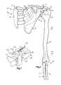
- FIG. 1is a schematic pictorial illustration depicting the manner in which a shoulder orthosis constructed in accordance with the present invention is connected with an arm and trunk of a body of a patient;
- FIG. 2is an illustration further depicting the construction of the shoulder orthosis of FIG. 1;
- FIG. 3is a front elevational view, taken generally along the line 3 — 3 of FIG. 2, further illustrating the construction of the shoulder orthosis;
- FIG. 4is a schematic illustration depicting bones in an arm and shoulder of a patient
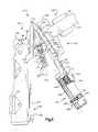
- FIG. 5is an enlarged fragmentary front elevational view of a portion of the shoulder orthosis of FIGS. 1-3, illustrating the manner in which a main and secondary drive assembly are connected with cuff arms;
- FIG. 6is a fragmentary elevational view, taken generally along the line 6 — 6 of FIG. 3, illustrating a lower cuff arm and a portion of the main drive assembly in the shoulder orthosis of FIGS. 1-3;
- FIG. 7(on sheet 4 of the drawings) is a fragmentary pictorial illustration of the manner in which a main gear in the drive assembly is mounted on a cuff arm of the orthosis of FIGS. 1 - 3 .
- a shoulder brace or orthosis 10effects relative movement between bones in a body 12 (FIG. 1) of a patient 14 .
- the shoulder orthosis 10is used to correct misalignment or malfunction of joints in a shoulder 16 of a patient.
- the shoulder orthosis 10has been illustrated in FIG. 1 as being utilized in association with a left arm 20 and shoulder 16 , the shoulder orthosis 10 could be constructed for use with a right arm 22 and shoulder 24 of the patient 14 if desired.
- the shoulder orthosis 10includes a base section 30 (FIGS. 1-3) which is connected with a trunk 32 (FIG. 1) of the patient's body.
- the base section 30is connected with the trunk 32 of the patient's body at a location beneath an armpit or axilla 34 .
- the axilla 34is formed at the connection between the left arm 20 and left shoulder 16 .
- the shoulder orthosis 10includes an upper arm section 38 (FIGS. 1-3) which is connected with the upper arm section 40 (FIG. 1) of the left arm 20 of the patient.
- a lower arm section 42 (FIGS. 1-3) of the shoulder orthosis 10is connected with a lower arm section 44 (FIG. 1) of the left arm 20 and a hand 46 of the patient 14 .
- a main drive assembly 50(FIGS. 1-3) interconnects the upper arm section 38 and the lower arm section 42 .
- the main drive assembly 50is manually operable by the patient 14 (FIG. 1) to move the lower section 44 of the arm 20 relative to the upper section 40 of the arm 20 .
- the main drive assembly 50is located adjacent to an elbow 54 which interconnects the upper and lower sections 40 and 44 of the arm 20 .
- the main drive assembly 50is operable to rotate bones in the arm 20 of the patient 14 relative to the shoulder 16 of the patient. Operation of the main drive assembly 50 rotates the bones in the arm 20 of the patient 14 about a longitudinal central axis of the upper arm section 40 .
- the main drive assembly 50can be operated in any one of two directions to effect either internal or external rotation of a humerus bone in upper arm section 40 relative to the shoulder 16 .
- a secondary drive assembly 58(FIGS. 1-3) is manually operable by the patient 14 to align the upper section 40 (FIG. 1) of the arm 20 of the patient 14 with the shoulder 16 of the patient.
- the secondary drive assembly 58is operable in either one of two directions to effect either abduction or adduction of the arm 20 .
- the secondary drive assembly 58is located beneath the armpit or axilla 34 .
- the secondary drive assemblyis positioned between the upper arm section 40 and the trunk 32 of the patient 14 .
- the secondary drive assembly 58is operable to move the upper arm section 40 into alignment with the shoulder 16 of the patient 14 .
- the secondary drive assembly 58is then effective to hold the upper arm section 40 in alignment with the shoulder 16 .
- the shoulder orthosis 10obtains release of soft tissue in the shoulder 16 and/or arm 20 of the patient.
- the shoulder orthosis 10effects elongation of viscoelastic tissue connected with the upper arm section 40 and the shoulder 16 of the patient.
- the main drive assembly 50is operated to rotate the humerus bone 62 (FIG. 4) in the upper arm section 40 relative to the shoulder 16 .
- Operation of the main drive assembly 50 (FIG. 1) to rotate the humerus bone 62 (FIG. 4)is interrupted when the viscoelastic body tissue has been stretched to a maximum extent compatible with a patient's comfort level.
- the main drive assembly 50is advantageously operated by the patient 14 himself/herself so that the patient can interrupt operation of the drive assembly when required in order to maintain patient comfort.
- the main drive assembly 50(FIG. 1) is constructed so that it continuously transmits force and is not operated in a reverse direction upon interruption of operation of the main drive assembly by the patient 14 . This results in tension being maintained in the viscoelastic body tissue interconnecting the upper section 40 of the arm 20 of the patient 14 and the shoulder 16 when operation of the main drive assembly 50 is interrupted. When a sufficient period of time to enable the viscoelastic tissue to relax has elapsed, the patient 14 again operates the main drive assembly 50 to further stretch the viscoelastic body tissue connected with the upper arm section 40 and shoulder 16 .
- the shoulder orthosis 10effects some distraction of the joint between the upper arm section 40 and shoulder 16 . This distraction occurs due to the combined weight of the shoulder orthosis 10 and the arm 20 .
- the trunk 32 of the patientincludes a shoulder joint 66 where the upper arm section 40 of the patient is connected with the trunk 32 of the patient.
- a head end portion 68 of the humerus bone 62 in the upper arm section 40is connected with the trunk 32 at the shoulder joint 66 .
- a radius bone 72 and an ulna bone 74 in the lower arm section 44are connected with the opposite or lower end of the humerus bone 62 .
- the head end portion 68 of the humerus bone 62is received in a glenoid cavity or fossa 80 formed in a scapula bone 82 at the shoulder joint 66 .
- the scapula bone 82articulates with the head end portion 68 of the humerus and the clavicle bone 84 .
- the clavicle or collarbone 84articulates with the sternum 86 and scapula bone 82 .
- the scapula bone 82is connected with rib bones 88 by body tissue.
- the shoulder joint 66is somewhat similar to a ball and socket joint.
- the head end portion 68 of the humerus bone 62has a configuration which may be considered as being hemispherical.
- the glenoid cavity 80forms a socket for the head end portion 68 of the humerus bone 62 .
- the socket formed by the glenoid cavity 80is shallow. Therefore, the glenoid cavity 80 may be considered as being a portion of a hemisphere.
- the head end portion 68 of the humerus bone 62has an arcuate outer side surface which is not truly hemispherical in configuration.
- the glenoid cavity 80has a configuration which may be considered as being generally ovate. Since the head end portion 68 of the humerus bone 62 and the glenoid cavity 80 are not true hemispheres, the motion which occurs between the bones at the shoulder 16 during movement of the arm 20 is far more complicated than a simple ball and socket analogy.
- a normal shoulder joint 66which functions in a proper manner can accommodate movement in all directions.
- a longitudinal central axis of the humerus bone 62should be aligned with a central portion of the glenoid cavity 80 .
- the longitudinal central axis of the humerus boneextends through or close to the center of the glenoid cavity.
- an arcuately curving, generally hemispherical outer side surface 92 on the head end portion 68 of the humerus bone 62is aligned with and is closely adjacent to a generally hemispherical side surface 94 of the glenoid cavity 80 .
- the outer side surface 92 on the head end portion 68 of the humerus bone 62 and the side surface 94 of the glenoid cavity 80do not have truly hemispherical configurations and do not have centers of curvature which are exactly coincident when the head end portion 68 of the humerus bone 62 is aligned with the glenoid cavity 80 . Therefore, there may be some shifting between the humerus bone 62 and the scapula bone 82 and/or clavicle bone 84 during rotation of the humerus bone 62 about its longitudinal central axis even though the longitudinal central axis of the humerus bone is aligned as close as is reasonably possible with the center of the glenoid cavity 80 .
- the lower arm section 42 (FIGS. 2, 3 and 6 ) of the shoulder orthosis 10is connected with the lower section 44 of the patient's arm 20 (FIG. 1 ).
- the lower arm section 42 of the shoulder orthosis 10(FIGS. 2, 3 and 6 ) includes a first or lower cuff arm 102 .
- the lower cuff arm 102includes a straight rigid metal outer channel member 104 and a straight rigid metal inner channel member 106 .
- the outer and inner channel members 104 and 106are disposed in a telescopic relationship with each other and are interconnected by a fastener 108 . When the fastener 108 is released, the outer channel member 104 and inner channel member 106 are longitudinally movable relative to each other to vary the extent of the lower arm section 42 of the orthosis 10 .
- a hand cuff 112is disposed on the axially outer end portion of the outer channel member 104 .
- the hand cuff 112is disposed on a rigid circular metal base 114 .
- the base 114is fixedly connected with the outer channel member 104 .
- a flexible hemisphere 118(FIG. 6) is connected to the metal base 114 and engages a palm of a hand 46 (FIG. 1) of the patient.
- a strap 120(FIGS. 2, 3 and 6 ) engages the back of the hand 46 of the patient.
- the strap 120presses the palm of the patient's hand against the hemisphere 118 .
- the hemisphere 118(FIGS. 2 and 6) has a radius which is sufficient to enable a portion of the palm of the patient's hand 46 (FIG. 1) to be further from the lower cuff arm 102 than a longitudinal central axis of the lower section 44 of the patient's arm 20 . This results in the patient's hand 46 being held in a relaxed, cup shaped configuration.
- the patient's hand 46is held against sidewise movement and the lower arm section 44 is stabilized on the lower arm section 42 of the orthosis 10 .
- a first or lower cuff 126is connected with the inner channel member 106 by the fastener 108 and a second fastener 128 (FIGS. 2, 3 and 6 ).
- the lower cuff 126includes a flexible polymeric body section 132 which is connected to the inner channel member 106 by the fasteners 108 and 128 .
- the body section 132extends part way around the lower arm section 44 of the patient 14 (FIG. 1 ).
- a central axis of the lower cuff 126extends parallel to the lower cuff arm 102 and extends through the hemisphere 118 in the hand cuff 112 .
- a strap 134(FIGS. 2, 3 and 6 ) is connected with the body section 132 and extends around the lower arm section 44 of the patient. Tightening the strap 134 causes the body portion 132 of the first or lower cuff 126 to flex inward and firmly grip the radius bone 72 and ulna bone 74 (FIG. 4) in the lower arm section 44 of the patient 14 (FIG. 1 ).
- the lower cuff 126 and hand cuff 112is illustrated in FIGS. 2, 3 and 6 , it is contemplated that these cuffs could have a different construction if desired.
- the lower arm section 42includes an elbow cuff 140 (FIGS. 2, 3 and 6 ) which is mounted on the inner channel member 106 .
- the elbow cuff 140includes a base plate 142 against which the elbow 54 (FIG. 1) in the arm 20 of the patient is pressed by a strap 144 . When the strap 144 is tightened, the elbow 54 is firmly held against movement relative to the lower arm section 42 .
- the elbow cuff 140could have a different construction or could be omitted if desired.
- the lower section 44 (FIG. 1) of the arm 20 of the patient 14is firmly held against movement relative to the lower cuff arm 102 by three different cuffs.
- the hand cuff 112holds the hand 46 of the patient 14 against movement relative to the lower cuff arm 102 .
- the first or lower cuff 126holds the lower arm section 44 of the arm 20 of the patient 14 against movement relative to the lower cuff arm 102 .
- the elbow cuff 140holds the elbow 54 of the patient 14 against movement relative to the lower cuff arm 102 .
- a central axis of the lower section of the arm of the patientextends through the hemisphere 118 .
- Forceis transmitted between the hemisphere 118 and palm of the hand 46 of the patient during operation of the shoulder orthosis 10 to effect external rotation of the arm 20 of the patient.
- forceis transmitted between the strap 120 and the back of the hand 46 of the patient during operation of the shoulder orthosis 10 to effect internal rotation of the arm 20 of the patient.
- the base plate 142 of the elbow cuff 140could be integrally formed as one piece with the body section 132 of the lower cuff.
- the lower cuff arm 102could be formed as a portion of the lower cuff 126 .
- the upper arm section 38 (FIG. 1) of the shoulder orthosis 10is connected with the upper section 40 of the patient's arm 20 .
- the upper arm section 38(FIGS. 2, 3 and 5 ) includes a second or upper cuff arm 150 .
- the upper cuff arm 150has a longitudinal axis which extends perpendicular to a longitudinal axis of the lower cuff arm 102 .
- the second or upper cuff arm 150includes a rigid straight metal lower channel member 152 (FIG. 5) and a rigid straight metal upper channel member 154 .
- the lower and upper channel members 152 and 154are telescopically adjustable relative to each other to accommodate patients having different length upper arm portions.
- Pin members 156are provided to fixedly interconnect the lower and upper channel members 152 and 154 when the second or upper cuff arm 150 has been adjusted to a desired length.
- the upper section 40 of the patient's arm 20(FIG. 1) is connected with the second or upper cuff arm 150 by an upper cuff 160 (FIGS. 2, 3 and 5 ).
- the upper cuff 160has a longitudinal central axis which extends perpendicular to and intersects a longitudinal central axis of the lower cuff 126 .
- the upper cuff 160includes a flexible polymeric body section 162 .
- the body section 162is fixedly connected to a connector channel 164 .
- the connector channel 164is fixedly connected to the upper channel member 154 of the upper cuff arm 150 .
- a flexible plastic tongue 168(FIG. 2) is connected with the body section 162 of the upper cuff 160 .
- a strap 172is connected with the opposite side of the body section 162 .
- the flexible tongue 158is positioned in engagement with the upper section 40 of the patient's arm 20 (FIG. 1 ).
- the strap 172is tightened to securely grip the upper section 40 of the patient's arm with the upper cuff 160 .
- the upper cuff 160could have a different construction if desired.
- the upper cuff arm 150could also have a construction which is different than the specific construction illustrated in the drawings. If desired, the upper cuff 160 could be constructed in such a manner as to enable the upper cuff arm 150 to be formed as a portion of the upper cuff.
- the base section 30 (FIGS. 1, 2 and 3 ) of the shoulder orthosis 10is connected with and is held against movement relative to the trunk 32 (FIG. 1) of the patient.
- the base section 30 of the orthosis 10includes a third or base cuff arm 178 (FIGS. 1, 2 and 3 ).
- the base cuff arm 178is formed by a single rigid straight metal channel member 180 .
- a third or base cuff 184is slidably connected with slots in the base cuff arm 178 by suitable fasteners (not shown).
- the fastenersenable the base cuff 184 to be released for movement axially along the base cuff arm 178 to position the base cuff 184 for engagement with the trunk 32 of different size patients 14 .
- the base cuff 184includes a body section 188 which is formed of a flexible polymeric material.
- a pad 190is connected with the body section 188 .
- the body section 188 and pad 190grip the trunk 32 of the patient at a location below the arm pit or axilla 34 (FIG. 1 ).
- the body section 188 of the third or base cuff 184is connected with the trunk 32 of the patient 14 by a pair of generally horizontal straps 192 and 194 (FIG. 1 ).
- the straps 192 and 194extend around the trunk 32 of the patient and are connected with opposite sides of the body section 188 of the base cuff 184 .
- a shoulder strap 198extends across the shoulder 24 to hold the body section 188 of the base cuff 184 in position on the trunk 32 of the patient 14 .
- the straps 192 , 194 , and 198cooperate with the body section 188 of the base cuff 184 to hold the base cuff stationary on the trunk 32 of the patient 14 .
- the base cuff arm 178 and the second or upper cuff arm 150are interconnected at a pivot connection 202 (FIGS. 1, 2 , 3 and 5 ).
- the pivot connection 202enables the upper cuff arm 150 to pivot about an axis which extends perpendicular to and intersects longitudinal central axes of the base cuff arm 178 and the second or upper cuff arm 150 .
- the pivot connection 202is positioned immediately beneath the armpit or axilla 34 (FIG. 1) on the body 12 of the patient 14 .
- the pivot connection 202enables the upper arm section 38 , main drive assembly 50 , and lower arm section 42 to be moved as a unit relative to the base section 30 of the orthosis 10 by operation of the secondary drive assembly 58 .
- the base cuff 184could have a construction which is different than the specific construction disclosed herein.
- the base cuff 184could be integrally formed as one piece with the upper cuff 160 .
- the base cuff arm 178could be formed as a portion of the base cuff 184 .
- the secondary drive assembly 58moves the upper arm section 40 and the lower arm section 44 of the arm 20 of the patient 14 relative to the shoulder 16 .
- the secondary drive assembly 58is operated to align the central axis of the humerus bone 62 (FIG. 4) in the upper arm section 40 with the center of the glenoid cavity 80 in the scapula bone 82 .
- the secondary drive assembly 58may be operated by either a therapist or the patient 14 . In order to promote patient confidence, it may be preferred to have the patient 14 operate the secondary drive assembly under the instruction of a therapist.
- the humerus bone 62can be rotated about its central axis while the scapula bone 82 and clavicle bone 84 remain substantially stationary relative to the trunk 32 of the patient 14 . This is because when the humerus bone 62 is aligned with the center of the glenoid cavity 80 , the central axis of the humerus bone 62 extends through a center of curvature of an arcuate surface 92 on the head end portion 68 of the humerus bone 62 and through a center of curvature of an arcuate surface 94 of the glenoid cavity 80 .
- the secondary drive assembly 58includes a rectangular tower or base frame 210 (FIG. 5 ).
- the tower or base frame 210extends downward from the pivot connection 202 between the base cuff arm 178 and the second or upper cuff arm 150 .
- the base cuff arm 178 and second or upper cuff arm 150are pivotal toward and away from the tower 210 about the pivot connection 202 .
- the tower 210has a central axis 212 (FIG. 5) which bisects an angle formed between the longitudinal central axis of the base cuff arm 178 and the longitudinal central axis of the second or upper cuff arm 150 .
- the longitudinal central axis 212 of the tower 210intersects and extends perpendicular to the axis about which the base cuff arm 178 and second or upper cuff arm 150 are pivotal at the pivot connection 202 .
- the secondary drive assembly 58includes a screw 214 (FIG. 5) having a central axis which is coincident with the central axis 212 of the tower 210 .
- the screw 214is rotatably supported in the tower 210 by suitable bearings.
- the screw 214has an external thread which engages an internal thread on an actuator block 216 . The cooperation between the external thread on the screw 214 and the internal thread between the actuator block 216 results in the actuator block moving toward or away from the pivot connection 202 during rotation of the screw 214 about its central axis.
- a pair of identical links 220 and 222extend between the actuator block 216 and the cuff arms 178 and 150 .
- the links 220 and 222maintain the actuator block and the screw 214 centered midway between the cuff arms 178 and 150 .
- a second pair of links having the same construction as the links 220 and 222are connected with the rear or posterior side of the actuator block 216 and the cuff arms 178 and 150 .
- the links on the posterior or rear side of the actuator block 216are aligned with the links 220 and 222 on the front or anterior side of the actuator block.
- a manually operable drive assembly 226(FIG. 5) is connected with the screw 214 .
- the drive assembly 226includes a worm 228 which engages a gear 230 .
- the gear 230is fixedly connected with the screw 214 .
- the worm 228is rotatable about an axis which extends perpendicular to coincident central axes of the gear 230 and screw 214 .
- the input member 232can be manually rotated by the patient 14 to adjust the extent of abduction of the arm 20 (FIG. 1) to a position of greatest comfort.
- the position of greatest comfortwill correspond to the position in which the longitudinal central axis of the humerus bone 62 (FIG. 4) is aligned with the center of the glenoid cavity 80 .
- the secondary drive assembly 58(FIG. 5) is constructed so that once the angle between the upper cuff arm 150 and the base cuff arm 178 has been adjusted by operation of the secondary drive assembly, the angle between the cuff arms is maintained constant.
- the secondary drive assemblyis constructed so that force applied to the base cuff arm 178 and upper cuff arm 150 cannot actuate the secondary drive assembly 58 to change the angle between the cuff arms. Therefore, once the central axis of the humerus bone has been aligned with the center of the glenoid cavity 80 by operation of the secondary drive assembly 58 , the humerus bone 62 is maintained in alignment with the center of the glenoid cavity.
- the secondary drive assembly 58has a construction which is generally similar to the construction of a drive assembly disclosed in U.S. Pat. No. 5,285,773. If desired, the secondary drive assembly 58 could have a different construction. For example, the secondary drive assembly 58 could be constructed in a manner similar to that disclosed in U.S. Pat. No. 5,503,619. Of course, other known drive assemblies could be substituted for the specific secondary drive assembly 58 illustrated in FIG. 5 .
- the main drive assembly 50(FIGS. 2 and 5) interconnects the upper cuff arm 15 G and the lower cuff arm 102 .
- the arm 20 (FIG. 1) of the patient 14is bent at a 90° angle at the elbow 54 . This allows upper section 20 of the patient's arm 20 to extend along the upper cuff arm 150 .
- the lower section 44 of the patient's arm 20extends along the lower cuff arm 102 .
- the elbow 54 and adjacent portions of the patient's arm 20extend through the main drive assembly 50 .
- the main drive assembly 50is operable to effect either internal or external rotation of the humerus bone 62 (FIG. 4) in the upper arm section 40 of the arm 20 relative to the shoulder joint 66 and scapula bone 82 . Operation of the main drive assembly 50 rotates the humerus bone 62 about its longitudinal central axis. To effect rotation of the humerus bone 62 , the main drive assembly 50 pivots the lower cuff arm 102 and lower section 44 of the patient's arm 20 about the longitudinal central axis of the humerus bone.
- the upper cuff arm 150 and base cuff arm 178are stationary relative to each other and the trunk 32 of the patient 14 during operation of the main drive assembly 50 and movement of the lower cuff arm 102 .
- the main drive assembly 50When the main drive assembly 50 is operated to rotate the humerus bone 62 about its longitudinal central axis, the secondary drive assembly 58 will have previously been adjusted to align the longitudinal central axis of the humerus bone with the center of the glenoid cavity 80 . Therefore, when the humerus bone 62 is rotated about its central axis, there is no substantial movement of the scapula bone 82 and/or clavicle bone 84 relative to each other and the trunk 32 of the patient 14 . It should be understood that the main drive assembly 50 is not operated to rotate the humerus bone 62 until after the secondary drive assembly 58 has been operated to position the humerus bone in alignment with the glenoid cavity 80 .
- the main drive assembly 50includes a main gear or drive member 240 which is fixedly connected with the lower cuff arm 102 (FIGS. 3 and 6 ).
- the main gear or drive member 240is rotatably connected with the upper cuff arm 150 .
- the elbow 54(FIG. 1) is disposed in the opening 244 (FIG. 6) in the main gear 240 .
- the elbow cuff 140holds the elbow in position relative to the main gear 240 and lower cuff arm 102 .
- the elbow 54is shown in FIG. 1 as being disposed in the opening 244 in the main gear 240 , a different portion of the arm 20 of the patient 14 could be disposed in the opening if desired.
- the main gear 240could be offset to one side, for example, downward, of the elbow 54 and rotatably connected with the upper cuff arm 150 . If this was done, the arm 20 of the patient 14 would not extend through the main gear 240 and the opening 244 could be eliminated.
- the main gear 240includes an arcuate array 248 (FIG. 6) of gear teeth 250 .
- the arcuate array 248 of gear teethhas a configuration of a portion of a circle.
- the central axis of the main gear 240extends parallel to the longitudinal central axis of the upper cuff arm 150 and is coincident with a longitudinal central axis of the upper section 40 (FIG. 1) of the arm 20 of the patient.
- the opening 244extends between opposite ends of the arcuate array 248 of gear teeth 250 to enable the arm 20 (FIG. 1) of the patient 14 to be readily moved into the opening in the main gear.
- the inner channel member 106 (FIG. 6) of the lower cuff arm 102extends into the opening 244 .
- the inner channel member 106is fixedly connected with the main gear 240 by suitable fasteners (not shown) which extend through the base plate 142 of the elbow cuff 140 .
- the inner channel member 106is fixedly connected to the main gear 240 with a central axis of the inner channel member extending perpendicular to the parallel central axes of the main gear and upper cuff arm 150 . Since the lower cuff arm 102 is fixedly connected with the main gear 240 , the lower cuff arm rotates with the main gear relative to the upper cuff arm 150 .
- the central axis of the humerus bone 62is substantially coincident with a central axis of the arcuate array 248 of gear teeth 250 (FIG. 6 ).
- the central axis of the lower section 44 (FIG. 1) of the patient's arm 20intersects the central axis of the upper section 40 of the patient's arm at a right angle at the elbow 54 .
- the intersection of the central axis of the upper section 40 and lower section 44 of the patient's arm 20is disposed in a central portion of the opening 244 in the main gear 240 .
- the main gear 240is disposed in meshing engagement with a pinion gear 256 (FIGS. 5 and 6 ).
- the pinion gear 256is rotatably mounted on the upper cuff arm 150 .
- the main gear 240is supported for rotation about the central axis of the opening 244 and the central axis of the upper arm section 40 of the arm 20 (FIG. 1) of the patient 14 by a positioning assembly 262 (FIG. 7 ).
- the positioning assembly 262is disposed on the anterior or back side of the main cuff arm 150 .
- the positioning assembly 262includes a pair of guide blocks 264 and 266 (FIG. 7) which engage axially opposite sides of the main gear 240 .
- the guide blocks 264 and 266are fixedly mounted on the upper cuff arm 150 .
- a pair of parallel pins 270 and 272extend from the guide block 262 into an arcuate groove 274 (FIGS. 6 and 7) formed in the main gear 240 .
- the pins 270 and 272extend into the arcuate groove 274 to guide rotational movement of the main gear 240 relative to the upper cuff arm 150 upon rotation of the pinion gear 256 (FIG. 6 ).
- a groove 274FIG.
- main gear 240could be offset from the central axis of the main gear. It is possible to have a portion of the arm 20 (FIG. 1) of the patient 14 extend into the opening 244 (FIG. 2) through the central portion of the main gear 240 .
- the main gear 240could be offset to one side of the arm of the patient and could be rotatably supported at its center if desired.
- the pinion drive 280includes a drive shaft 284 (FIG. 5) which is fixedly connected with the pinion gear 256 .
- a second pinion gear 286is fixedly connected to the drive shaft 284 in a coaxial relationship with the pinion gear 256 .
- a worm 290is disposed in meshing engagement with the second pinion gear 286 .
- the worm 290is driven by a reversible ratchet 294 (FIG. 2 ).
- the reversible ratchet 294is connected with the worm 290 by an input shaft 296 .
- the ratchet 294extends in the anterior direction, that is frontward, from the upper cuff arm 150 . This enables the ratchet 294 to be manually operated by the patient 14 .
- the patientoperates the main drive assembly 50 by actuating the ratchet 294 under the influence of force transmitted from the right arm 22 (FIG. 1) of the patient to the ratchet 294 .
- a therapistmay assist in operation of the ratchet 294 if desired.
- the reversible ratchet 294can be actuated to rotate the main gear 240 in either one of two directions to effect either internal or external rotation of the humerus bone 62 in the upper arm section 40 of the patient 14 .
- the straps 192 , 194 , and 198 for the base cuff 184(FIG. 1 ), a strap 144 for the elbow cuff 440 , the strap 134 for the lower cuff 126 , and the strap 120 for the hand cuff 112 are all released in the manner illustrated in FIG. 2 .
- the body section 188 of the base cuff 184is then positioned in engagement with the trunk 32 of the patient 14 .
- the straps 192 , 194 and 198are then pulled only tight enough to loosely hold the base cuff 184 in position on the trunk 32 of the patient.
- the connection 202 between the base cuff arm 178 and the upper cuff arm 150is disposed approximately one inch below the arm pit or axilla 34 (FIG. 1) of the patient 14 .
- the arm 20 of the patientis positioned in the upper cuff 160 and the lower cuff 126 .
- the elbow of the patientis positioned in the elbow cuff 140 .
- the lower cuff 126is then tightened to grip the lower arm section 44 .
- the elbow cuff 140 and the hand cuff 112are then tightened.
- the upper cuff 160is then tightened.
- the orthosisis adjusted so that the patient's shoulder is 30 degrees scapular plane.
- the upper arm 40 of the patientextends forward at an angle of approximately 30°.
- the straps 192 , 194 and 198are then tightened to hold the shoulder orthosis 10 firmly in place.
- the input knob 232 of the secondary drive assembly 58is then actuated to a plane approximately 45° of abduction of the shoulder 16 of the patient. At this time, the arm 20 is positioned in the plane of the scapula.
- the aforementioned stepsmay be performed by the patient alone or by the patient with the help of a therapist.
- the patientoperates the main drive assembly 50 to effect either external or internal rotation of the humerus bone 62 in the upper section 40 of the arm 20 .
- the patient 14manually rotates the ratchet 294 (FIG. 2 ).
- Rotation of the ratchet 294rotates the worm 290 and drive shaft 284 .
- Rotation of the drive shaft 284rotates the pinion gear 256 and main gear 240 .
- the main gear 240is rotated relative to the upper cuff arm 150
- the humerus bone 62is rotated about its central axis. Rotation of the humerus bone 62 stretches viscoelastic tissue in the shoulder joint 66 .
- the stretched viscoelastic body tissue connected with the humerus bone 62begins to relax. With the passage of a relatively short interval of time, for example fifteen minutes, the viscoelastic body tissue will have relaxed sufficiently to enable the patient 14 to again operate the main drive assembly 50 to further stretch the viscoelastic tissue. As the patient operates the main drive assembly 50 to further stretch the viscoelastic body tissue, the main gear 240 and the lower cuff arm are rotated relative to the upper cuff arm 150 .
- the shoulder orthosis 10is removed from the body 12 of the patient 14 .
- the direction of operation of the ratchet 294is reversed and the main drive assembly 50 operated to release the pressure against the lower section 44 of the arm 20 of the patient.
- the various cuffsare loosened and the orthosis 10 is removed from the patient until the next treatment is undertaken.
- a new and improved apparatus 10 for effecting relative movement between bones in a body 12 of a patient 14includes a first cuff 126 which grips a lower portion 44 of an arm 20 of the patient.
- a second cuff 160grips an upper portion 40 of the arm 20 of the patient.
- a drive assembly 50is operable to rotate the first cuff 126 and a humerus bone 62 in the arm 20 of the patient 14 about a central axis of the humerus bone. This results in a stretching of viscoelastic tissue connected with a head end portion 68 of the humerus bone 16 .
- the extent of stretching of the viscoelastic tissue connected with a humerus bone 62 in the arm 20 of the patient 14may be maximized by interrupting operation of the drive assembly 50 to allow the viscoelastic body tissue to relax. After the viscoelastic body tissue has relaxed, the drive assembly 50 is again operated to further rotate the first cuff 126 and further stretch the viscoelastic body tissue connected with the humerus bone 62 .
- a secondary drive assembly 58is provided to pivot the humerus bone 62 in the arm 20 of the patient 14 about the head end portion 68 of the humerus bone. This moves an arcuate surface 92 on the head end portion 68 of the humerus bone 62 into alignment with an arcuate surface 94 of a glenoid cavity 80 in a scapula bone 82 in the shoulder 16 of the patient 14 .
- the secondary drive assembly 58is disposed beneath an axilla 34 between the trunk 32 and arm 20 of the patient 14 .
Landscapes
- Health & Medical Sciences (AREA)
- Animal Behavior & Ethology (AREA)
- Veterinary Medicine (AREA)
- Public Health (AREA)
- General Health & Medical Sciences (AREA)
- Life Sciences & Earth Sciences (AREA)
- Engineering & Computer Science (AREA)
- Nursing (AREA)
- Orthopedic Medicine & Surgery (AREA)
- Biomedical Technology (AREA)
- Heart & Thoracic Surgery (AREA)
- Vascular Medicine (AREA)
- Rehabilitation Therapy (AREA)
- Physical Education & Sports Medicine (AREA)
- Pain & Pain Management (AREA)
- Epidemiology (AREA)
- Prostheses (AREA)
- Orthopedics, Nursing, And Contraception (AREA)
- Surgical Instruments (AREA)
Abstract
Description
Claims (32)
Priority Applications (6)
| Application Number | Priority Date | Filing Date | Title |
|---|---|---|---|
| US09/579,038US6599263B1 (en) | 1998-06-01 | 2000-05-26 | Shoulder orthosis |
| US10/626,951US6929616B2 (en) | 1998-06-01 | 2003-07-25 | Shoulder orthosis |
| US10/760,598US7955285B2 (en) | 1998-06-01 | 2004-01-20 | Shoulder orthosis |
| US13/155,132US8591442B2 (en) | 1998-06-01 | 2011-06-07 | Shoulder orthorsis |
| US14/066,883US9345606B2 (en) | 1998-06-01 | 2013-10-30 | Shoulder orthosis |
| US15/149,645US20160250057A1 (en) | 1998-06-01 | 2016-05-09 | Shoulder Orthosis |
Applications Claiming Priority (2)
| Application Number | Priority Date | Filing Date | Title |
|---|---|---|---|
| US09/088,134US6113562A (en) | 1998-06-01 | 1998-06-01 | Shoulder orthosis |
| US09/579,038US6599263B1 (en) | 1998-06-01 | 2000-05-26 | Shoulder orthosis |
Related Parent Applications (1)
| Application Number | Title | Priority Date | Filing Date |
|---|---|---|---|
| US09/088,134DivisionUS6113562A (en) | 1998-06-01 | 1998-06-01 | Shoulder orthosis |
Related Child Applications (1)
| Application Number | Title | Priority Date | Filing Date |
|---|---|---|---|
| US10/626,951ContinuationUS6929616B2 (en) | 1998-06-01 | 2003-07-25 | Shoulder orthosis |
Publications (1)
| Publication Number | Publication Date |
|---|---|
| US6599263B1true US6599263B1 (en) | 2003-07-29 |
Family
ID=22209559
Family Applications (7)
| Application Number | Title | Priority Date | Filing Date |
|---|---|---|---|
| US09/088,134Expired - LifetimeUS6113562A (en) | 1998-06-01 | 1998-06-01 | Shoulder orthosis |
| US09/579,038Expired - LifetimeUS6599263B1 (en) | 1998-06-01 | 2000-05-26 | Shoulder orthosis |
| US10/626,951Expired - Fee RelatedUS6929616B2 (en) | 1998-06-01 | 2003-07-25 | Shoulder orthosis |
| US10/760,598Expired - Fee RelatedUS7955285B2 (en) | 1998-06-01 | 2004-01-20 | Shoulder orthosis |
| US13/155,132Expired - Fee RelatedUS8591442B2 (en) | 1998-06-01 | 2011-06-07 | Shoulder orthorsis |
| US14/066,883Expired - Fee RelatedUS9345606B2 (en) | 1998-06-01 | 2013-10-30 | Shoulder orthosis |
| US15/149,645AbandonedUS20160250057A1 (en) | 1998-06-01 | 2016-05-09 | Shoulder Orthosis |
Family Applications Before (1)
| Application Number | Title | Priority Date | Filing Date |
|---|---|---|---|
| US09/088,134Expired - LifetimeUS6113562A (en) | 1998-06-01 | 1998-06-01 | Shoulder orthosis |
Family Applications After (5)
| Application Number | Title | Priority Date | Filing Date |
|---|---|---|---|
| US10/626,951Expired - Fee RelatedUS6929616B2 (en) | 1998-06-01 | 2003-07-25 | Shoulder orthosis |
| US10/760,598Expired - Fee RelatedUS7955285B2 (en) | 1998-06-01 | 2004-01-20 | Shoulder orthosis |
| US13/155,132Expired - Fee RelatedUS8591442B2 (en) | 1998-06-01 | 2011-06-07 | Shoulder orthorsis |
| US14/066,883Expired - Fee RelatedUS9345606B2 (en) | 1998-06-01 | 2013-10-30 | Shoulder orthosis |
| US15/149,645AbandonedUS20160250057A1 (en) | 1998-06-01 | 2016-05-09 | Shoulder Orthosis |
Country Status (1)
| Country | Link |
|---|---|
| US (7) | US6113562A (en) |
Cited By (46)
| Publication number | Priority date | Publication date | Assignee | Title |
|---|---|---|---|---|
| US20030144334A1 (en)* | 1998-08-05 | 2003-07-31 | Walter Guarnieri | Cyclopentabenzofuran derivatives and their use |
| US20040193086A1 (en)* | 2003-03-28 | 2004-09-30 | Cofre Ruth P. | Dynamic position adjustment device for extremities of the human body |
| US20050197605A1 (en)* | 2004-03-08 | 2005-09-08 | Bonutti Boris P. | Orthosis |
| US20060020237A1 (en)* | 2004-07-22 | 2006-01-26 | Nordt William E Iii | Two-component compression collar clamp for arm or leg |
| US20060030803A1 (en)* | 2004-07-22 | 2006-02-09 | Nordt Development Co., Llc | Donning potentiating support with expandable framework spanning hinge joint |
| US20060026732A1 (en)* | 2004-07-22 | 2006-02-09 | Nordt Development Co., Llc | Support with framework fastened to garment |
| US20060030804A1 (en)* | 2004-07-22 | 2006-02-09 | Nordt Development Co., Llc | Potentiating support with side struts spanning hinge joint |
| US20060030806A1 (en)* | 2004-07-22 | 2006-02-09 | Nordt Development Co., Llc | Potentiating support with alignment opening for joint protuberance |
| US20060026736A1 (en)* | 2004-07-22 | 2006-02-09 | Nordt Development Co., Llc | Clothing having expandable framework |
| US20060030805A1 (en)* | 2004-07-22 | 2006-02-09 | Nordt Development Co., Llc | Support with removable pressure/alignment ring |
| US20060026733A1 (en)* | 2004-07-22 | 2006-02-09 | Nordt Development Co., Llc | Shirt, pants and jumpsuit having expandable framework |
| US20060070165A1 (en)* | 2004-07-22 | 2006-04-06 | Nordt Development Co., Llc | Donning potentiating support with expandable framework fastened to garment |
| US20060070164A1 (en)* | 2004-07-22 | 2006-04-06 | Nordt Development Co., Llc | Donning support with framework fastened to garment |
| USD519637S1 (en) | 2004-07-22 | 2006-04-25 | Nordt Development Co., Inc. | Support brace |
| USD519638S1 (en) | 2004-07-22 | 2006-04-25 | Nordt Development Co., Inc. | Support brace member |
| USD520141S1 (en) | 2004-07-22 | 2006-05-02 | Nordt Development Co., Inc. | Support brace |
| USD521644S1 (en) | 2004-07-22 | 2006-05-23 | Nordt Development Co., Inc. | Support brace |
| US20070055190A1 (en)* | 2004-03-08 | 2007-03-08 | Bonutti Boris P | Range of motion device |
| US20070100267A1 (en)* | 2005-10-28 | 2007-05-03 | Bonutti Boris P | Range of motion device |
| WO2008036895A2 (en) | 2006-09-21 | 2008-03-27 | Marctec, Llc | Range of motion device |
| US20080188356A1 (en)* | 2007-02-05 | 2008-08-07 | Bonutti Boris P | Knee orthosis |
| US7473234B1 (en) | 2004-05-24 | 2009-01-06 | Deroyal Industries, Inc. | Brace with worm gear |
| WO2009015364A1 (en) | 2007-07-25 | 2009-01-29 | Bonutti Research Inc. | Orthosis apparatus and method of using an orthosis apparatus |
| US7547290B1 (en) | 2004-06-18 | 2009-06-16 | Waleed Al-Oboudi | Orthotic device |
| US7618389B2 (en) | 2004-07-22 | 2009-11-17 | Nordt Development Co., Llc | Potentiating support with expandable framework |
| US20090326422A1 (en)* | 2006-09-01 | 2009-12-31 | Worcester Polytechnic Institute | Two degree of freedom powered orthosis |
| US7704219B2 (en) | 2004-07-22 | 2010-04-27 | Nordt Development Company, Llc | Wrist support |
| US7955285B2 (en) | 1998-06-01 | 2011-06-07 | Bonutti Research Inc. | Shoulder orthosis |
| US7988653B2 (en) | 2009-01-08 | 2011-08-02 | Breg, Inc. | Orthopedic elbow brace having a length-adjustable support assembly |
| US8012108B2 (en) | 2005-08-12 | 2011-09-06 | Bonutti Research, Inc. | Range of motion system and method |
| US8038637B2 (en) | 2000-09-18 | 2011-10-18 | Bonutti Research, Inc. | Finger orthosis |
| US20110270145A1 (en)* | 2010-04-29 | 2011-11-03 | Mark Nail | Hand-Arm Stabilizer For Immobilizing A Person's Wrist While Allowing That Person To Hold And Operate A Hand Held Device |
| US8062241B2 (en) | 2000-12-15 | 2011-11-22 | Bonutti Research Inc | Myofascial strap |
| US8251934B2 (en) | 2000-12-01 | 2012-08-28 | Bonutti Research, Inc. | Orthosis and method for cervical mobilization |
| US20120231903A1 (en)* | 2011-03-07 | 2012-09-13 | Gear Llc | Apparatuses for improving throwing technique and methods of using same |
| US8672864B2 (en) | 2004-07-22 | 2014-03-18 | Nordt Development Co., Llc | Body support for spanning a hinge joint of the body comprising an elastically stretchable framework |
| CN101808600B (en)* | 2007-07-27 | 2014-04-09 | 奥托伯克保健有限公司 | Shoulder orthosis |
| US8905950B2 (en) | 2008-03-04 | 2014-12-09 | Bonutti Research, Inc. | Shoulder ROM orthosis |
| US9402759B2 (en) | 2013-02-05 | 2016-08-02 | Bonutti Research, Inc. | Cervical traction systems and method |
| US10058994B2 (en) | 2015-12-22 | 2018-08-28 | Ekso Bionics, Inc. | Exoskeleton and method of providing an assistive torque to an arm of a wearer |
| US10369069B2 (en) | 2014-10-07 | 2019-08-06 | Allen Medical Systems, Inc. | Surgical arm positioning systems and methods |
| USD876654S1 (en) | 2018-04-24 | 2020-02-25 | Ossur Iceland Ehf | Posterior strut |
| US10569413B2 (en) | 2015-12-22 | 2020-02-25 | Ekso Bionics, Inc. | Exoskeleton and method of providing an assistive torque to an arm of a wearer |
| US10918559B2 (en) | 2017-04-25 | 2021-02-16 | Ossur Iceland Ehf | Interface system in an exoskeleton |
| US11000439B2 (en) | 2017-09-28 | 2021-05-11 | Ossur Iceland Ehf | Body interface |
| US11497671B2 (en) | 2017-10-02 | 2022-11-15 | University Of Strathclyde | Apparatus for the rehabilitation, assistance and/or augmentation of arm strength in a user |
Families Citing this family (69)
| Publication number | Priority date | Publication date | Assignee | Title |
|---|---|---|---|---|
| FR2806905B1 (en)* | 2000-03-29 | 2003-02-28 | Smith & Nephew Kinetec Sa | ARM PASSIVE MOBILIZATION SPACE |
| US6685662B1 (en)* | 2001-07-16 | 2004-02-03 | Therapeutic Enhancements, Inc | Weight bearing shoulder device |
| US6537237B1 (en) | 2001-09-28 | 2003-03-25 | R & R Holdings, Llc | Orthotic device |
| US7048704B2 (en)* | 2001-09-28 | 2006-05-23 | Sieller Richard T | Orthotic device |
| US7547289B2 (en)* | 2001-12-13 | 2009-06-16 | Ermi Corporation | Shoulder extension control device |
| US6866646B2 (en)* | 2001-12-31 | 2005-03-15 | R & R Holdings, Llc | Supination/pronation therapy device |
| DE10208406A1 (en)* | 2002-02-27 | 2003-09-11 | Univ Regensburg Klinikum | Variable arm abduction orthosis |
| US20060184081A1 (en)* | 2002-05-28 | 2006-08-17 | Gilmour Robert F | Enhanced arm brace |
| US20040010213A1 (en)* | 2002-07-10 | 2004-01-15 | Mav-Tech Medical L.L.C. | Stabilizer brace system |
| US7182738B2 (en) | 2003-04-23 | 2007-02-27 | Marctec, Llc | Patient monitoring apparatus and method for orthosis and other devices |
| US7563236B2 (en)* | 2003-09-15 | 2009-07-21 | Djo, Llc | Shoulder sling with support pillow and pouch |
| US7686775B2 (en)* | 2004-04-09 | 2010-03-30 | Branch Thomas P | Method and apparatus for multidirectional positioning of a shoulder |
| DE102004028604A1 (en)* | 2004-06-07 | 2005-12-22 | Paul Hartmann Ag | Bandage for the shoulder and upper arm area |
| US8834169B2 (en)* | 2005-08-31 | 2014-09-16 | The Regents Of The University Of California | Method and apparatus for automating arm and grasping movement training for rehabilitation of patients with motor impairment |
| TWM311417U (en)* | 2006-10-20 | 2007-05-11 | Univ Nat Cheng Kung | Forearm rehabilitation apparatus |
| US7717834B2 (en)* | 2007-06-12 | 2010-05-18 | Kay Scott A | Therapeutic shoulder apparatus |
| US8545373B2 (en)* | 2007-07-12 | 2013-10-01 | Peter Scott Borden | Shoulder stretcher and method of use |
| EP2052709A1 (en)* | 2007-10-24 | 2009-04-29 | ETH Zurich | System for arm therapy |
| WO2009076725A1 (en)* | 2007-12-19 | 2009-06-25 | Mark Sorrenti | Shoulder brace |
| US9358173B2 (en)* | 2008-05-09 | 2016-06-07 | National Taiwan University | Rehabilitation and training apparatus and method of controlling the same |
| USD598116S1 (en)* | 2008-05-15 | 2009-08-11 | Otto Bock Healthcare Ip Gmbh & Co., Kg | Orthosis |
| FR2932081B1 (en)* | 2008-06-10 | 2010-05-14 | Commissariat Energie Atomique | SHOULDER MECHANISM FOR ORTHESIS. |
| US7662119B2 (en)* | 2008-07-21 | 2010-02-16 | Anatomical Concepts, Inc. | Multiple function ratcheting orthotic device |
| US7682323B2 (en)* | 2008-07-21 | 2010-03-23 | Anatomical Concepts, Inc. | Coordinated cuff displacement in an orthotic device |
| WO2010039540A2 (en)* | 2008-09-23 | 2010-04-08 | Kelly Robert A | Shoulder continuous passive motion device |
| KR101065420B1 (en)* | 2008-12-16 | 2011-09-16 | 한양대학교 산학협력단 | Wearable robotic device for upper limb movement |
| EP2501345A4 (en) | 2009-11-18 | 2017-12-06 | Cradle Medical, Inc. | Shoulder immobilizer and fracture stabilization device |
| US20120310118A1 (en)* | 2010-02-08 | 2012-12-06 | Sarver Joseph J | Shoulder torque and range of motion device |
| KR101106876B1 (en)* | 2010-03-31 | 2012-01-25 | 이화여자대학교 산학협력단 | Pollution prevention device to prevent water pollution |
| US8852063B2 (en)* | 2010-06-01 | 2014-10-07 | Bua Dunne Enterprise, LLC | Humerus-stabilized shoulder stretch device |
| DE102010049191A1 (en)* | 2010-10-21 | 2012-04-26 | Albrecht Gmbh | Dynamic shoulder joint orthosis, especially shoulder abduction orthosis, with floating upper arm splint part |
| US8591441B2 (en) | 2010-10-22 | 2013-11-26 | Peter M. Bonutti | Shoulder orthosis including flexion/extension device |
| US9918864B2 (en)* | 2011-10-03 | 2018-03-20 | Breg, Inc. | Brace for correction of humeral fractures |
| FR2991224B1 (en)* | 2012-06-04 | 2014-06-27 | Commissariat Energie Atomique | ARM OF EXOSQUELET WITH ACTUATOR |
| DE102012014541B3 (en) | 2012-07-17 | 2013-12-05 | Bauerfeind Ag | Schulterabduktionsorthese |
| US9636268B1 (en)* | 2013-06-18 | 2017-05-02 | Darlene Bedillion | Articulating surgical armrest |
| WO2015050897A1 (en)* | 2013-10-01 | 2015-04-09 | Djo, Llc | Orthopedic shoulder device |
| JP6133756B2 (en)* | 2013-11-12 | 2017-05-24 | 株式会社デンソー | Arm support device |
| TWI507187B (en)* | 2013-11-26 | 2015-11-11 | Air-cushioned shoulder-rotator cuff rehabilitation apparatus | |
| ES2544890B2 (en)* | 2014-03-04 | 2016-05-09 | Universidad Politécnica de Madrid | Robotic exoskeleton with self-adjusting sliding elbow support for human arm |
| US10220234B2 (en)* | 2014-06-04 | 2019-03-05 | T-Rex Investment, Inc. | Shoulder end range of motion improving device |
| CN104287936B (en)* | 2014-10-22 | 2015-10-28 | 华中科技大学 | A kind of coupled motions mechanism and comprise the device for healing and training shoulder joint of this mechanism |
| JP6709214B2 (en)* | 2014-10-24 | 2020-06-10 | エンハンス テクノロジーズ, リミテッド ライアビリティー カンパニーEnhance Technologies, LLC | Arm support system |
| US10376404B2 (en) | 2015-03-27 | 2019-08-13 | Ossur Iceland Ehf | Orthopedic device for scapulothoracic stabilization |
| JP1541566S (en)* | 2015-04-02 | 2016-01-18 | ||
| JP1541565S (en)* | 2015-04-02 | 2016-01-18 | ||
| USD830913S1 (en)* | 2015-04-02 | 2018-10-16 | Denso Corporation | Arm rest apparatus |
| US11013620B2 (en) | 2015-06-26 | 2021-05-25 | Victoria Hand Project | Custom fitted body powered prosthetic upper limb manufactured by 3D printing |
| US10285841B2 (en)* | 2015-09-04 | 2019-05-14 | Rojan John Pappady | Stabilizing and mobility-enhancing brace for the shoulder joint |
| US10568797B1 (en)* | 2015-11-04 | 2020-02-25 | ScoliWRx, Inc. | Spinal cord and meninges stretching frame and method to prevent and treat the root cause of scoliosis |
| TWI626068B (en)* | 2015-11-27 | 2018-06-11 | 國立臺北科技大學 | Arm strength training rehabilitation equipment |
| CN105853141B (en)* | 2016-03-28 | 2018-06-15 | 南京邮电大学 | Shoulder rehabilitation system with gravity compensation |
| CN106214419B (en)* | 2016-07-14 | 2018-06-08 | 大连理工大学 | Adaptive forearm muscle group convalescence device |
| CN106974800B (en)* | 2017-04-13 | 2019-05-24 | 铜陵海思康健康科技有限公司 | A kind of cure scapulohumeral periarthritis protector |
| KR102025625B1 (en)* | 2017-09-11 | 2019-09-27 | 콜럼비아헬스케어 주식회사 | Apparatus for assisting shoulder |
| US11622877B2 (en)* | 2018-06-04 | 2023-04-11 | Brandon O. DAVIES-SEKLE | Dynamic range of motion orthosis |
| US20200038217A1 (en)* | 2018-08-01 | 2020-02-06 | Manvir Singh Purewal | Manual Therapist Support Apparatus |
| CN109011404B (en)* | 2018-08-16 | 2021-08-27 | 冯跃 | Shoulder joint rehabilitation training medical equipment |
| CN109512636B (en)* | 2018-11-09 | 2020-12-01 | 义乌市根号三科技有限公司 | Second-stage passive exercise instrument for upper limb fracture function rehabilitation |
| EP3866733A4 (en) | 2018-12-31 | 2021-12-15 | Nuwellis, Inc. | PORTABLE ARMREST FOR BLOOD FLOW SUPPORT |
| CN109875747B (en)* | 2019-03-06 | 2021-03-30 | 王国梁 | An arm fixation sleeve for surgical patients |
| US20220228710A1 (en)* | 2019-05-02 | 2022-07-21 | Virginia Tech Intellectual Properties, Inc. | Gravity compensation mechanisms and methods |
| US11564815B2 (en) | 2019-09-17 | 2023-01-31 | Victoria Hand Project | Upper arm prosthetic apparatus and systems |
| CN111281631B (en)* | 2020-03-06 | 2021-09-14 | 西北工业大学 | Medical auxiliary instrument for adjusting force line of lower limbs of human body |
| US12138205B2 (en)* | 2020-07-22 | 2024-11-12 | The Board Of Regents Of The University Of Texas System | Wheelchair arm rest device |
| US11957606B2 (en) | 2020-10-29 | 2024-04-16 | Victoria Hand Project | Low-cost prosthetic apparatus, methods, kits, and systems with improved force transfer elements |
| US20230013131A1 (en)* | 2021-07-16 | 2023-01-19 | Adonis Medical Technologies Ltd. | Dynamic shoulder brace |
| GB2624025A (en)* | 2022-11-04 | 2024-05-08 | Earswitch Ltd | Brace apparatus |
| CN116763521B (en)* | 2023-07-25 | 2024-03-15 | 北京积水潭骨科机器人工程研究中心有限公司 | Shoulder joint restorer |
Citations (18)
| Publication number | Priority date | Publication date | Assignee | Title |
|---|---|---|---|---|
| US2590729A (en)* | 1948-06-16 | 1952-03-25 | Scognamillo Engineering Compan | Rotary compressor |
| US4180870A (en) | 1975-04-15 | 1980-01-01 | Fa Wilh. Jul. Teufel | Universal-orthese |
| US4241731A (en)* | 1978-05-11 | 1980-12-30 | Pauley James H | Universal arm support |
| US4653479A (en)* | 1985-01-17 | 1987-03-31 | Empi, Inc. | Interrupted drive limb motion apparatus |
| US4957281A (en)* | 1989-01-30 | 1990-09-18 | Wright State University | Rotator cuff therapeutic exercise apparatus |
| US5163451A (en)* | 1990-12-19 | 1992-11-17 | Sutter Corporation | Rehabilitation patient positioning method |
| US5285773A (en) | 1990-07-30 | 1994-02-15 | Peter M. Bonutti | Orthosis with distraction through range of motion |
| US5385536A (en)* | 1993-03-01 | 1995-01-31 | Wayne Z. Burkhead | Orthopedic brace for arm and shoulder |
| US5391132A (en) | 1992-09-16 | 1995-02-21 | Greenwald; Dale R. | Free standing rotator cuff development device |
| US5407420A (en) | 1992-11-12 | 1995-04-18 | Smith & Nephew Donjoy, Inc. | Fully adjustable shoulder brace |
| US5417643A (en) | 1993-10-27 | 1995-05-23 | Danninger Medical Technology, Inc. | Continuous passive motion exercise device |
| US5503619A (en) | 1990-07-30 | 1996-04-02 | Bonutti; Peter M. | Orthosis for bending wrists |
| US5520181A (en) | 1993-11-24 | 1996-05-28 | Technology Funding Secured Investors Ii | Positioning device for producing movement in the shoulder |
| US5788659A (en)* | 1996-12-13 | 1998-08-04 | Haas; Michael John | Shoulder traction device for relocating a dislocated shoulder |
| US5848979A (en) | 1996-07-18 | 1998-12-15 | Peter M. Bonutti | Orthosis |
| US5919148A (en)* | 1996-03-27 | 1999-07-06 | Marko; Alexei J. | Apparatus and method for evaluation of shoulder stability |
| US6007500A (en)* | 1998-01-28 | 1999-12-28 | Quintinskie, Jr.; John J. | Shoulder, rotator cuff, and elbow stretching machine |
| US6113562A (en)* | 1998-06-01 | 2000-09-05 | Peter M. Bonutti | Shoulder orthosis |
Family Cites Families (255)
| Publication number | Priority date | Publication date | Assignee | Title |
|---|---|---|---|---|
| US417643A (en)* | 1889-12-17 | Grain-bag folder | ||
| US433227A (en)* | 1890-07-29 | Thirds to charles it | ||
| US432327A (en) | 1890-07-15 | William i | ||
| DE405327C (en) | 1924-03-19 | 1924-10-31 | Fritz Groenert | Stretching device to remedy shortened tendons |
| US2223276A (en) | 1937-12-17 | 1940-11-26 | Thomas C Ward | Cervical splint |
| US2246689A (en) | 1938-05-09 | 1941-06-24 | Kost Alwin | Mechanical movement |
| US2191283A (en)* | 1938-07-02 | 1940-02-20 | Harry H Leiter | Splint |
| US2237252A (en) | 1939-09-27 | 1941-04-01 | Harry Herschel Leiter | Surgical arm rest and support therefor |
| US2250493A (en) | 1940-06-10 | 1941-07-29 | George M Milne | Foot and leg exercising device |
| US2535489A (en)* | 1947-03-05 | 1950-12-26 | Harold T Edwards | Artificial arm |
| US2590739A (en) | 1949-07-26 | 1952-03-25 | Wagner Hugo | Orthopedic bone aligning and fixing mechanism |
| US2829562A (en) | 1953-02-03 | 1958-04-08 | Rue Richard M La | Cartridge feeding mechanism |
| US2811154A (en) | 1953-07-20 | 1957-10-29 | William M Scholl | Stretchable bandage |
| US2820455A (en) | 1953-12-28 | 1958-01-21 | Newton J Hall | Neck brace |
| US2832334A (en) | 1956-05-23 | 1958-04-29 | Stephen H Whitelaw | Therapeutic device for use in manipulative treatment of joints of the human body |
| US3083708A (en) | 1960-08-08 | 1963-04-02 | Jobst Institute | Sleeve or legging for stimulating flow of fluids within an animal body |
| US3351055A (en) | 1963-11-26 | 1967-11-07 | Jobst Institute | Pressure bandage-splint and method of forming same |
| US3338237A (en) | 1964-10-20 | 1967-08-29 | Sconce Jerry Wayne | Pneumatic splint |
| US3548818A (en) | 1968-03-14 | 1970-12-22 | David Kaplan | Shoulder brace |
| US3580248A (en)* | 1968-12-02 | 1971-05-25 | Leighton W Larson | Bivalved cast |
| US3760056A (en)* | 1970-09-23 | 1973-09-18 | Bogert R | Method for custom fitting an inflatable bladder to a wearer{3 s foot |
| US3724452A (en)* | 1971-03-04 | 1973-04-03 | Green T | Cervical brace |
| US3701349A (en)* | 1971-05-13 | 1972-10-31 | Leighton W Larson | Bi-valved cast |
| US3698389A (en)* | 1971-05-21 | 1972-10-17 | Guedel Co Inc | Elbow locking device |
| US3811434A (en)* | 1972-10-26 | 1974-05-21 | Jacobson S Mfg | Inflatable splint |
| US3795243A (en)* | 1973-01-29 | 1974-03-05 | J Miller | Ambulatory traction device for cervical problems |
| US3814419A (en)* | 1973-06-04 | 1974-06-04 | L Bjorklund | Arm exercising device |
| US3955565A (en)* | 1973-12-05 | 1976-05-11 | Johnson Jr Glenn W | Orthopedic apparatus |
| US3856004A (en)* | 1973-12-26 | 1974-12-24 | Comfort Care Prod | Clavicle brace |
| US3976057A (en)* | 1974-12-23 | 1976-08-24 | Clarence F. Bates | Joint flexing apparatus |
| US3970316A (en)* | 1975-03-27 | 1976-07-20 | Diversified Products, Inc. | Golf swing restrictor |
| AT338410B (en) | 1975-09-18 | 1977-08-25 | Viennatone Gmbh | TRANSMISSION FOR AN ORTHESIS, PROSTHESIS OR DGL. |
| US4039183A (en) | 1976-04-21 | 1977-08-02 | Ritshyo Kogyo Kabushiki Kaisha | Wrist exercise and strengthening device |
| US4076022A (en) | 1976-12-20 | 1978-02-28 | James Walker | Therapeutic foot and leg protector |
| US4108170A (en) | 1977-03-24 | 1978-08-22 | Spann Donald C | Patient support strap |
| US4285773A (en) | 1977-08-27 | 1981-08-25 | Alberta Oil Sands Technology And Research Authority | Apparatus and process for recovery of hydrocarbon from inorganic host materials |
| US4214577A (en) | 1978-02-27 | 1980-07-29 | Hoy Mansell I | Orthosis for exercising joint |
| DE2829562A1 (en) | 1978-07-05 | 1980-01-17 | Klaus Muenich | Machine for exercising part of human body - has motor reversing switch actuated by lever coupled to winch drum |
| US4237873A (en) | 1978-12-11 | 1980-12-09 | Hoyt Laurance J Sr | Cerebral palsy arm and hand brace |
| US4229001A (en) | 1979-02-23 | 1980-10-21 | Roman Michael P | Therapeutic exercise device |
| US4273113A (en) | 1979-10-29 | 1981-06-16 | World Medical Marketing Corporation | Foot exerciser |
| US4383523A (en) | 1980-06-13 | 1983-05-17 | Schurman John R | Cervical brace |
| SE435451B (en) | 1980-08-08 | 1984-10-01 | Olle Blomqvist | DEVELOPMENT QUADRICE TRAINING DEVICE |
| US4454871A (en) | 1980-09-29 | 1984-06-19 | Med-Con, Inc. | Ankle-foot orthosis |
| US4363481A (en) | 1980-11-20 | 1982-12-14 | Erickson David T | Exercise device |
| US4320748A (en) | 1980-11-20 | 1982-03-23 | Orthomedics, Inc. | Fracture brace |
| US4441489A (en) | 1981-03-10 | 1984-04-10 | National Research Development Corporation | Orthopaedic splints |
| US4370977A (en) | 1981-05-04 | 1983-02-01 | Kenneth D. Driver | Knee and elbow brace |
| US4508111A (en) | 1981-07-23 | 1985-04-02 | Dynasplint Systems, Inc. | Adjustable splint |
| US4417569A (en)* | 1981-10-19 | 1983-11-29 | Alexander Mencher | Universal functional shoulder orthosis |
| CA1181306A (en) | 1981-10-23 | 1985-01-22 | Toronto Medical Corp. | Device for imparting continuous passive motion to human joints |
| US4456001A (en) | 1982-07-02 | 1984-06-26 | Electro-Biology, Inc. | Apparatus for equine hoof treatment |
| US4502470A (en) | 1982-09-16 | 1985-03-05 | Kiser John L | Physiologic device and method of treating the leg extremities |
| US4456002A (en) | 1982-09-27 | 1984-06-26 | L M B Hand Rehab Products | Spring metacarpophalangeal flexion splint (knuckle splint) |
| US4570619A (en) | 1982-10-27 | 1986-02-18 | Jung Corporation | Clavicle brace |
| US4509509A (en) | 1983-07-11 | 1985-04-09 | Jean Bouvet | Apparatus for treating the joints of the human body |
| US4589406A (en) | 1983-08-11 | 1986-05-20 | Florek Florian F | Orthopaedic appliance for use in treating acromioclavicular joint injuries |
| SU1158195A1 (en) | 1983-09-20 | 1985-05-30 | 9-Я Городская Клиническая Больница Г.Запорожья | Apparatus for developing contractures of upper limb |
| US4538600A (en) | 1983-10-27 | 1985-09-03 | Dynasplint Systems, Inc. | Adjustable splint |
| DE3345386A1 (en)* | 1983-12-15 | 1985-06-27 | Ernst Knoll Feinmechanik, 7801 Umkirch | ARM SUPPORT DEVICE |
| US4628913A (en) | 1984-01-13 | 1986-12-16 | United States Manufacturing Co. | Cervical thoracic orthosis |
| US4538595A (en) | 1984-02-21 | 1985-09-03 | Hajianpour Muhamad A | Passive exercising device |
| US4576151A (en) | 1984-03-19 | 1986-03-18 | Carmichael Hoagy C | Orthopedic leg appliance |
| US4612919A (en) | 1984-10-03 | 1986-09-23 | Best Walter E | Adjustable limb support |
| US4606542A (en) | 1984-10-30 | 1986-08-19 | David Segal | Limb muscle exercising |
| US4574635A (en) | 1984-11-02 | 1986-03-11 | North American Philips Corporation | Monitoring of frequency shift of ultrasound pulses in tissue |
| US4727865A (en) | 1985-03-07 | 1988-03-01 | Hill Byrne Christopher R | Replaceable rigid cast with integral fasteners |
| US4805601A (en) | 1985-03-15 | 1989-02-21 | Eischen Sr Clement G | Device for lower limb extremity having weight-response pressure chambers |
| US4641639A (en) | 1985-12-09 | 1987-02-10 | Rigoberto Padilla | Ambulatory brace assembly |
| ZA869406B (en) | 1985-12-16 | 1987-11-25 | Glenn W Johnson Jr | Pneumatic braces |
| US4807601A (en) | 1985-12-20 | 1989-02-28 | Empi, Inc. | Live display appartus for setting extenson and flexion limits in continuous passive motion (CPM) system |
| US4693239A (en) | 1986-01-21 | 1987-09-15 | Orthomedics, Inc. | Orthosis |
| US4809688A (en) | 1986-04-22 | 1989-03-07 | Empresa Cubana Importadora Y. Exportadora Of Products Medicos, T/A Medicuba | Sinergic splint for early mobilization of the flexor tendons of the hand |
| US4665905A (en) | 1986-06-09 | 1987-05-19 | Brown Charles S | Dynamic elbow and knee extension brace |
| US4718665A (en) | 1986-07-15 | 1988-01-12 | Soma Dynamics Corporation | Exercise device |
| US4793334A (en) | 1986-07-22 | 1988-12-27 | Mcguinness Charles G | Cervical brace |
| US5156589A (en) | 1986-09-05 | 1992-10-20 | Karl Otto Braun Kg | Cohesive bandage |
| US4739334A (en) | 1986-09-30 | 1988-04-19 | The United States Of America As Represented By The Secretary Of The Air Force | Electro-optical beamforming network for phased array antennas |
| US4913135A (en) | 1986-12-16 | 1990-04-03 | Mattingly Leslie G | Cervical brace |
| US4834073A (en) | 1987-02-20 | 1989-05-30 | Medical Technology, Inc. | Passive motion exerciser |
| US4765320A (en) | 1987-05-11 | 1988-08-23 | Smith & Nephew Rolyan, Inc. | Dynamic low profile splint |
| CA1270472A (en) | 1987-05-14 | 1990-06-19 | Gerald P. Villeneuve | Safety belt |
| US4913755A (en) | 1988-03-16 | 1990-04-03 | Royce Medical Company | Method of forming orthopaedic gel pads |
| US5027801A (en) | 1987-05-29 | 1991-07-02 | Royce Medical Company | Orthopaedic gel pad assembly |
| US4844094A (en) | 1987-05-29 | 1989-07-04 | Royce Medical Company | Ankle brace |
| US5018514A (en) | 1987-06-11 | 1991-05-28 | Brace Technologies, Inc. | Knee brace |
| US4790301A (en) | 1987-10-23 | 1988-12-13 | Krister Silfverskiold | Device for and method of dynamic splinting |
| US4862877A (en) | 1987-11-18 | 1989-09-05 | Lmb Hand Rehab Products, Inc. | Hand splint for wrist support with optional support of MP joints and thumb and IP finger assists |
| US4844455A (en) | 1987-12-21 | 1989-07-04 | Har-Tru Corporation | Tennis net tightening apparatus |
| US4955396A (en) | 1988-02-05 | 1990-09-11 | Northwest Marine Technology, Inc. | Method for tagging macro-organisms |
| US4869267A (en) | 1988-05-10 | 1989-09-26 | Royce Medical Company | Adjustable tension ankle support |
| USRE34661E (en) | 1988-05-10 | 1994-07-12 | Royce Medical Company | Gel and air cushion ankle brace |
| US5027688A (en) | 1988-05-18 | 1991-07-02 | Yamaha Corporation | Brace type angle-detecting device for musical tone control |
| US5135470A (en) | 1988-05-25 | 1992-08-04 | Bryan Reeves | Shoulder and back support brace |
| US4848326A (en) | 1988-06-20 | 1989-07-18 | Robert Lonardo | Knee contracture correction device |
| US4844454A (en) | 1988-07-15 | 1989-07-04 | Rogers Stephen A | Portable, manually operable knee exerciser |
| US4953543A (en) | 1988-08-09 | 1990-09-04 | Royce Medical Company | Cruciate ligament leg brace |
| US4964402A (en) | 1988-08-17 | 1990-10-23 | Royce Medical Company | Orthopedic device having gel pad with phase change material |
| GB2225239A (en)* | 1988-09-12 | 1990-05-30 | Protectair Ltd | Orthopaedic brace |
| US4865024A (en) | 1988-10-21 | 1989-09-12 | Hensley Dvid E | Extension deceleration orthosis |
| US4955369A (en) | 1988-10-27 | 1990-09-11 | Bledsoe Gary R | Dynamically shiftable counter shear force knee brace |
| US4884454A (en) | 1988-11-14 | 1989-12-05 | Lifting Technologies, Inc. | Manbasket testing apparatus and method |
| SU1671296A1 (en) | 1988-11-21 | 1991-08-23 | Ленинградский научно-исследовательский детский ортопедический институт им.Г.И.Турнера | Orthopedic appliance for upper limb |
| US4869499A (en) | 1989-01-17 | 1989-09-26 | Schiraldo Donald R | Toe exercise device |
| US4930497A (en) | 1989-01-23 | 1990-06-05 | Toronto Medical Corp. | Apparatus for imparting continuous passive motion to a lower limb |
| US5252102A (en) | 1989-01-24 | 1993-10-12 | Electrobionics Corporation | Electronic range of motion apparatus, for orthosis, prosthesis, and CPM machine |
| CA2008248A1 (en) | 1989-01-24 | 1990-07-24 | Robert D. Singer | Electronic range of motion apparatus, for orthosis, prosthesis and cpm machine |
| US5052379A (en) | 1989-04-27 | 1991-10-01 | Soma Dynamics Corporation | Combination brace and wearable exercise apparatus for body joints |
| US5019050A (en) | 1989-05-30 | 1991-05-28 | Lynn Karen K | Securing device and method |
| US5027802A (en) | 1989-06-16 | 1991-07-02 | Donohue Patrick T | Multi-mode digital traction system |
| US4991234A (en) | 1989-10-10 | 1991-02-12 | Bert Greenberg | Body support band |
| US4996979A (en) | 1989-10-13 | 1991-03-05 | Royce Medical Company | Soft-goods type, formable orthopaedic cast |
| JP2818223B2 (en) | 1989-10-26 | 1998-10-30 | アルケア株式会社 | Medical stretch cloth |
| US5749840A (en) | 1989-12-07 | 1998-05-12 | Ultraflex Systems, Inc. | Dynamic splint |
| US5036837A (en) | 1990-02-09 | 1991-08-06 | Bio-Tec, Inc. | Dynamic extension splint |
| US5025782A (en) | 1990-02-12 | 1991-06-25 | Ambulatory Traction Inc. | Adjustable rack and pinion knee brace |
| US5823975A (en) | 1990-02-21 | 1998-10-20 | Stark; John G. | Local monitoring system for an instrumented orthopedic restraining device and method therefor |
| US5929782A (en) | 1990-02-21 | 1999-07-27 | Stark; John G. | Communication system for an instrumented orthopedic restraining device and method therefor |
| US5052375A (en) | 1990-02-21 | 1991-10-01 | John G. Stark | Instrumented orthopedic restraining device and method of use |
| US5201702A (en) | 1990-04-17 | 1993-04-13 | Mars Suzanne P | Brace for supporting the head in an upright position |
| FR2661333B1 (en) | 1990-04-25 | 1993-04-23 | Caruana Patrick | MULTI-JOINT MUSCLE EXERCISE APPARATUS. |
| US5376091A (en) | 1990-06-08 | 1994-12-27 | Smith & Nephew Richards, Inc. | Dynamic finger support |
| US5100403A (en) | 1990-06-08 | 1992-03-31 | Smith & Nephew Richards, Inc. | Dynamic elbow support |
| US5102411A (en) | 1990-06-08 | 1992-04-07 | Hotchkiss Robert N | Dynamic elbow support |
| US5005563A (en) | 1990-06-18 | 1991-04-09 | Veale Charles J | Mobile-cervical extension and supporting apparatus |
| US5464385A (en) | 1990-06-27 | 1995-11-07 | Royce Medical Company | Walker with open heel |
| US5078128A (en) | 1990-06-27 | 1992-01-07 | Royce Medical Company | Removable leg walker |
| US5036838A (en) | 1990-07-16 | 1991-08-06 | Applied Technology International, Ltd. | Foam plastic orthopedic fabric |
| US5685830A (en) | 1990-07-30 | 1997-11-11 | Bonutti; Peter M. | Adjustable orthosis having one-piece connector section for flexing |
| US5167612A (en) | 1990-07-30 | 1992-12-01 | Bonutti Peter M | Adjustable orthosis |
| US5213094A (en) | 1990-07-30 | 1993-05-25 | Bonutti Peter M | Orthosis with joint distraction |
| US5139475A (en) | 1990-08-14 | 1992-08-18 | Francis Robicsek | Medical appliance for treating venous insufficiency |
| DE4029120A1 (en) | 1990-09-13 | 1992-03-19 | Habermeyer Peter | Splint for broken limbs - comprises two shell parts clampable against one another between which and limb are cushions |
| US5088481A (en) | 1990-10-10 | 1992-02-18 | Darco International Inc. | Casted foot medical boot with dual pivot points |
| US5070866A (en) | 1990-10-25 | 1991-12-10 | Alexander William K | Woven back support belt with rigidity control |
| US5116359A (en) | 1990-12-05 | 1992-05-26 | Moore Joseph L | Head, neck and shoulder therapeutic exercise device |
| US5203321A (en) | 1990-12-11 | 1993-04-20 | Sutter Corporation | Passive anatomic ankle-foot exerciser |
| US5211161A (en) | 1991-01-22 | 1993-05-18 | Compagnie Generale De Materiel Orthopedique | Three axis passive motion exerciser |
| US5466250A (en) | 1991-01-23 | 1995-11-14 | Aircast, Inc. | Automatic fluid compress and circulating system |
| US5201772A (en) | 1991-01-31 | 1993-04-13 | Maxwell Scott M | System for resisting limb movement |
| US5213095A (en) | 1991-02-06 | 1993-05-25 | Dague Lawrence M | Coupling apparatus for scuba gear |
| US5191903A (en) | 1991-06-06 | 1993-03-09 | Donohue Patrick T | Digital traction system |
| US5141489A (en) | 1991-07-26 | 1992-08-25 | Sereboff Joel L | Cervical brace |
| US5255188A (en) | 1991-09-16 | 1993-10-19 | Jace Systems, Inc. | Universal controller for continuous passive motion devices |
| US5453082A (en) | 1991-09-20 | 1995-09-26 | Lamont; William D. | Protective medical boot with pneumatically adjustable orthotic splint |
| US5226245A (en) | 1991-09-20 | 1993-07-13 | Lamont William D | Protective boot structure |
| US5535274A (en) | 1991-10-19 | 1996-07-09 | Cellport Labs, Inc. | Universal connection for cellular telephone interface |
| US5277695A (en) | 1991-11-08 | 1994-01-11 | Aircast, Inc. | Adjustable ankle compress |
| US5349956A (en) | 1991-12-04 | 1994-09-27 | Apogee Medical Products, Inc. | Apparatus and method for use in medical imaging |
| US5261125A (en) | 1992-01-08 | 1993-11-16 | Rudolph Cartwright | Head impact force diversion system |
| US5197942A (en) | 1992-01-13 | 1993-03-30 | Harold Brady | Customized foot orthosis |
| US5252101A (en) | 1992-01-24 | 1993-10-12 | Breslow, Morrison, Terzian & Associates, Inc. | Simulated toy commode |
| US5297540A (en) | 1992-01-29 | 1994-03-29 | Jace Systems, Inc. | Continuous passive motion orthosis device for a toe |
| US5232435A (en) | 1992-02-04 | 1993-08-03 | Saul Leibinsohn | Splint |
| US5352189A (en) | 1992-02-19 | 1994-10-04 | Tecnol Medical Products, Inc. | Ankle brace walker |
| US5492133A (en) | 1992-02-19 | 1996-02-20 | Aircast, Inc. | Improved flexible fastening strap |
| US5218954A (en) | 1992-07-09 | 1993-06-15 | Bemmelen Paul S Van | Arterial assist device and method |
| US5316022A (en) | 1992-08-28 | 1994-05-31 | Schiek Sr James W | Sports belt with cinchable fastener system |
| CA2091092A1 (en) | 1992-09-03 | 1994-03-04 | Orthologic Corp. | Continuous passive motion device |
| GB2271060B (en) | 1992-10-01 | 1996-04-03 | Huntleigh Technology Plc | An inflatable garment |
| US5378223A (en) | 1992-10-23 | 1995-01-03 | Royce Medical Company | Orthopedic support pad and method for providing semi-permanent relief zones |
| US5312322A (en) | 1992-11-02 | 1994-05-17 | The United States Of America As Represented By The Secretary Of The Navy | Three point extension splint to treat flexion contractures about limb synovial hinge joints |
| CA2092581C (en) | 1992-12-22 | 2003-10-14 | Judith K. Faass | Self-adhesive nonwoven elastic compressible composite material |
| US5419757A (en) | 1992-12-28 | 1995-05-30 | Daneshvar; Yousef | Support containing shaped balloons |
| US5329705A (en) | 1993-02-16 | 1994-07-19 | Royce Medical Company | Footgear with pressure relief zones |
| US5328448A (en) | 1993-03-16 | 1994-07-12 | Gray Sr Richard O | Finger joint therapy apparatus |
| US5520620A (en) | 1993-04-26 | 1996-05-28 | Johnson; Lanny L. | Shoulder brace |
| US5372597A (en) | 1993-05-12 | 1994-12-13 | Smith & Nephew Richards, Inc. | Supination-pronation device |
| US5354260A (en) | 1993-05-13 | 1994-10-11 | Novamedix, Ltd. | Slipper with an inflatable foot pump |
| US5389065A (en) | 1993-06-15 | 1995-02-14 | Aircast, Inc. | Ankle brace with ATF compression |
| US5421874A (en) | 1993-06-22 | 1995-06-06 | Genesis Composites, L.C. | Composite microsphere and lubricant mixture |
| US5437619A (en) | 1993-06-30 | 1995-08-01 | Empi, Inc. | Range-of-motion splint with eccentric spring |
| US5466213A (en) | 1993-07-06 | 1995-11-14 | Massachusetts Institute Of Technology | Interactive robotic therapist |
| WO1995001769A2 (en) | 1993-07-09 | 1995-01-19 | Kinetecs, Inc. | Exercise apparatus and technique |
| US5609570A (en) | 1993-07-12 | 1997-03-11 | Lamed, Inc. | Protective medical boot and orthotic splint |
| US5323435A (en) | 1993-07-16 | 1994-06-21 | Combustion Engineering Inc. | Control rod housing support bars with wing assemblies |
| US5348530A (en) | 1993-07-29 | 1994-09-20 | Royce Medical Company | Pneumatic ankle brace with bladder and pump arrangement |
| US5792084A (en) | 1993-08-10 | 1998-08-11 | Smith & Nephew, Inc. | Knee brace having an inflatable pad circumscribing the patella |
| US5456286A (en) | 1993-08-17 | 1995-10-10 | A. W. Chesterton Co. | Shaft seal coolant flow control |
| US5364323A (en) | 1993-09-09 | 1994-11-15 | Tony Liu | Multi-directional rotatable wrist exerciser |
| US5472407A (en) | 1993-10-13 | 1995-12-05 | Schenck; Robert R. | Motorized dynamic traction device |
| US5403265A (en) | 1993-11-03 | 1995-04-04 | Lunax Corporation | Pressure sock |
| US5626537A (en) | 1993-11-23 | 1997-05-06 | Danyo; J. Joseph | Exercise compliance apparatus and method |
| US5437611A (en) | 1993-12-01 | 1995-08-01 | Orthotic Rehabilitation Products, Inc. | Dynamic brace joint |
| DE9319990U1 (en) | 1993-12-24 | 1994-03-10 | Medi Bayreuth GmbH & Co. KG, 95448 Bayreuth | Ankle orthosis |
| US5370133A (en) | 1994-02-22 | 1994-12-06 | Darco International, Inc. | Lower leg, ankle and foot immobilization brace with uniform, adjustable compression |
| US5520628A (en) | 1994-04-18 | 1996-05-28 | Wehr; Maxon P. | Ankle encompassing pressure orthosis |
| US5472410A (en) | 1994-04-22 | 1995-12-05 | Deroyal/Lmb, Inc. | Adjustable flexion and extension joint orthoses |
| US5538499A (en)* | 1994-05-27 | 1996-07-23 | Orthomerica Products, Inc. | Orthopaedic shoulder brace having adjustable pelvic, scapulary, and arm supports |
| US5538486A (en) | 1994-06-03 | 1996-07-23 | Hoggan Health Industries, Inc. | Instrumented therapy cord |
| GB9411445D0 (en) | 1994-06-08 | 1994-07-27 | Univ Brunel | A splint |
| US5407422A (en) | 1994-10-04 | 1995-04-18 | Sharon C. Hanson | Pelvic belt |
| US5571077A (en) | 1994-10-18 | 1996-11-05 | Lake Medical Products, Inc. | Self-supporting foot orthosis with pivotally mounted cover |
| US5755679A (en) | 1994-10-20 | 1998-05-26 | Selner; Allen J. | Apparatus for foot stabilizer |
| US5531669A (en) | 1994-11-18 | 1996-07-02 | Center For Prosthetics Orthotics, Inc. | Cervical brace with interlock assembly |
| US5518009A (en) | 1994-11-28 | 1996-05-21 | Ruiz-Gonzalez; Susan | Apparatus for treating colic in infants |
| US5575764A (en) | 1994-12-14 | 1996-11-19 | Van Dyne; Leonard A. | Prosthetic joint with dynamic torque compensator |
| US5577998A (en) | 1995-02-03 | 1996-11-26 | Aircast, Incorporated | Walking brace |
| US5772619A (en) | 1995-04-07 | 1998-06-30 | Corbett; Blake | Pivotal brace for prosthesis |
| US5605535A (en) | 1995-05-01 | 1997-02-25 | Lepage; Jeffrey A. | Ankle positioning splint |
| US5645521A (en)* | 1995-06-22 | 1997-07-08 | Dynasplint Systems, Inc. | Shoulder physical therapy device |
| US5653680A (en) | 1995-08-10 | 1997-08-05 | Cruz; Mark K. | Active wrist brace |
| US5833639A (en) | 1995-10-27 | 1998-11-10 | Johnson & Johnson Professional, Inc. | Short leg walker |
| US5778565A (en) | 1995-11-28 | 1998-07-14 | Royce Medical Company | Versatile orthopaedic or post-operative footgear having removable toe piece |
| US5681269A (en) | 1995-12-13 | 1997-10-28 | Smith & Nephew Rolyan Inc. | Joint extension splint |
| US5647378A (en) | 1996-04-23 | 1997-07-15 | Farnum; Randal J. | Invalid support belt |
| US5820577A (en) | 1996-09-26 | 1998-10-13 | Taylor; Terrence M. | Finger exercise device |
| US6142965A (en) | 1997-02-25 | 2000-11-07 | Mathewson; Paul R. | Variably adjustable bi-directional derotation bracing system |
| US6464652B1 (en) | 1997-03-06 | 2002-10-15 | Corsolutions, Inc. | Methods and equipment for treating or preventing muscle pain or injury |
| US6142964A (en) | 1997-03-27 | 2000-11-07 | Bodyworks Properties Limited | Multi-planar brace |
| US5839139A (en) | 1997-04-24 | 1998-11-24 | John Fink | Heel elevator for the prevention of heel and foot ulcerations |
| US5882320A (en) | 1997-07-11 | 1999-03-16 | Peterson; Lloyd E. | Disposable cast or bandage protector |
| US5949148A (en)* | 1997-07-18 | 1999-09-07 | Wagner; William F. | D.C. power distribution and fuse panel unit |
| US5882323A (en) | 1997-09-18 | 1999-03-16 | Belkin; Julie | Polycentric hinged ulnar deviation hand splint |
| DE19745705C1 (en) | 1997-10-16 | 1999-02-11 | Beiersdorf Ag | Arm bandage with open construction |
| US6059576A (en) | 1997-11-21 | 2000-05-09 | Brann; Theodore L. | Training and safety device, system and method to aid in proper movement during physical activity |
| US6001075A (en) | 1997-12-12 | 1999-12-14 | Ex. P.H. | Dynamic splint |
| US5865773A (en) | 1998-01-28 | 1999-02-02 | Koledin; Michael J. | Cervical extrication collar |
| US5943705A (en) | 1998-03-05 | 1999-08-31 | Sink; Michael D. | Athletic equipment attachment strap |
| US5940992A (en) | 1998-03-16 | 1999-08-24 | Darco International, Inc. | Surgical shoe for avoiding heel strike and for reducing weight bearing from the heel of a foot |
| US6027468A (en) | 1998-03-18 | 2000-02-22 | Aircast, Inc. | Walking brace with enhanced shock absorbency |
| US6021780A (en) | 1998-07-09 | 2000-02-08 | Darco International, Inc. | Immobilization brace with overlapping ventilation ports within semi-flexible boot and foam sheet material liner |
| US6267742B1 (en) | 1998-09-29 | 2001-07-31 | Brown Medical Industries | Biplanar foot dorsiflexion collapsible posterior splint |
| US6093162A (en) | 1998-11-16 | 2000-07-25 | Fairleigh; Angela | Dynamic splint for post-operative treatment of flexible implant arthroplasty of the fingers |
| JP4261657B2 (en) | 1998-12-22 | 2009-04-30 | キヤノン株式会社 | Manufacturing method of color filter |
| US6228044B1 (en) | 1999-01-05 | 2001-05-08 | Rose Biomedical Research | Methods and apparatus for treating plantar ulcerations |
| US6179747B1 (en) | 1999-01-22 | 2001-01-30 | Lillie P. Kelley | One piece face and neck exerciser |
| US6053169A (en) | 1999-02-22 | 2000-04-25 | Hunt; Dermot A. | Medical strap for treating injured patient |
| US6384755B1 (en) | 1999-04-09 | 2002-05-07 | Hewlett-Packard Company | Method and apparatus for analog to digital conversion using an impedance device as an identifier |
| US6371123B1 (en) | 1999-06-11 | 2002-04-16 | Izex Technology, Inc. | System for orthopedic treatment protocol and method of use thereof |
| US6409691B1 (en) | 1999-08-02 | 2002-06-25 | Daos Limited | Liquid brace |
| JP2001087296A (en) | 1999-09-21 | 2001-04-03 | Hideki Shiraishi | Dynamic splint with towing (fulcrum) movable outrigger |
| CA2402814C (en) | 2000-03-14 | 2009-01-20 | Orthorehab Inc. | Control device for the therapeutic mobilization of joints |
| US6485447B1 (en) | 2000-05-25 | 2002-11-26 | Salix Medical, Inc. | Foot support device with adjustable forefoot rocker angle |
| US6436058B1 (en) | 2000-06-15 | 2002-08-20 | Dj Orthopedics, Llc | System and method for implementing rehabilitation protocols for an orthopedic restraining device |
| US6572571B2 (en) | 2000-08-31 | 2003-06-03 | Richard Dean Lowe | Limb stabilizer |
| US6502577B1 (en) | 2000-09-18 | 2003-01-07 | Peter M. Bonutti | Method for moving finger joints |
| US6637429B2 (en) | 2000-11-20 | 2003-10-28 | Annette M. Mundrick | Pediatric abdominal support |
| US6503213B2 (en) | 2000-12-01 | 2003-01-07 | Peter M. Bonutti | Method of using a neck brace |
| US6575926B2 (en) | 2000-12-15 | 2003-06-10 | Bonutti 2003 Trust-A | Myofascial strap |
| US6599255B2 (en) | 2001-05-31 | 2003-07-29 | Rehabilitation Institute Of Chicago | Portable intelligent stretching device |
| US6890285B2 (en) | 2001-10-01 | 2005-05-10 | Tariq Rahman | Brace compliance monitor |
| US6509659B1 (en) | 2001-10-24 | 2003-01-21 | Motorola, Inc. | Cable or module identification apparatus and method |
| ATE535216T1 (en) | 2002-04-25 | 2011-12-15 | Ultraflex Systems Inc | MOVABLE KNEE JOINT |
| US7182738B2 (en) | 2003-04-23 | 2007-02-27 | Marctec, Llc | Patient monitoring apparatus and method for orthosis and other devices |
| US6974431B2 (en) | 2003-04-24 | 2005-12-13 | Medefficiency, Inc. | Apparatus and method for applying a total contact cast |
| US7204814B2 (en) | 2003-05-29 | 2007-04-17 | Muscle Tech Ltd. | Orthodynamic rehabilitator |
| US7452342B2 (en) | 2004-03-08 | 2008-11-18 | Bonutti Research Inc. | Range of motion device |
| US7112179B2 (en) | 2004-03-08 | 2006-09-26 | Marc Tec, Llc | Orthosis |
| US8066656B2 (en) | 2005-10-28 | 2011-11-29 | Bonutti Research, Inc. | Range of motion device |
| US7473234B1 (en) | 2004-05-24 | 2009-01-06 | Deroyal Industries, Inc. | Brace with worm gear |
| DE102004039509B4 (en) | 2004-08-14 | 2006-09-21 | Sanofi-Aventis Deutschland Gmbh | Aryl-cycloalkyl substituted alkanoic acid derivatives, process for their preparation and their use as medicaments |
| US8012108B2 (en) | 2005-08-12 | 2011-09-06 | Bonutti Research, Inc. | Range of motion system and method |
| US8251935B2 (en) | 2006-03-17 | 2012-08-28 | Bonutti Research, Inc. | Ankle orthosis |
| US7955286B2 (en) | 2006-03-20 | 2011-06-07 | Bonutti Research Inc. | Elbow orthosis |
- 1998
- 1998-06-01USUS09/088,134patent/US6113562A/ennot_activeExpired - Lifetime
- 2000
- 2000-05-26USUS09/579,038patent/US6599263B1/ennot_activeExpired - Lifetime
- 2003
- 2003-07-25USUS10/626,951patent/US6929616B2/ennot_activeExpired - Fee Related
- 2004
- 2004-01-20USUS10/760,598patent/US7955285B2/ennot_activeExpired - Fee Related
- 2011
- 2011-06-07USUS13/155,132patent/US8591442B2/ennot_activeExpired - Fee Related
- 2013
- 2013-10-30USUS14/066,883patent/US9345606B2/ennot_activeExpired - Fee Related
- 2016
- 2016-05-09USUS15/149,645patent/US20160250057A1/ennot_activeAbandoned
Patent Citations (18)
| Publication number | Priority date | Publication date | Assignee | Title |
|---|---|---|---|---|
| US2590729A (en)* | 1948-06-16 | 1952-03-25 | Scognamillo Engineering Compan | Rotary compressor |
| US4180870A (en) | 1975-04-15 | 1980-01-01 | Fa Wilh. Jul. Teufel | Universal-orthese |
| US4241731A (en)* | 1978-05-11 | 1980-12-30 | Pauley James H | Universal arm support |
| US4653479A (en)* | 1985-01-17 | 1987-03-31 | Empi, Inc. | Interrupted drive limb motion apparatus |
| US4957281A (en)* | 1989-01-30 | 1990-09-18 | Wright State University | Rotator cuff therapeutic exercise apparatus |
| US5285773A (en) | 1990-07-30 | 1994-02-15 | Peter M. Bonutti | Orthosis with distraction through range of motion |
| US5503619A (en) | 1990-07-30 | 1996-04-02 | Bonutti; Peter M. | Orthosis for bending wrists |
| US5163451A (en)* | 1990-12-19 | 1992-11-17 | Sutter Corporation | Rehabilitation patient positioning method |
| US5391132A (en) | 1992-09-16 | 1995-02-21 | Greenwald; Dale R. | Free standing rotator cuff development device |
| US5407420A (en) | 1992-11-12 | 1995-04-18 | Smith & Nephew Donjoy, Inc. | Fully adjustable shoulder brace |
| US5385536A (en)* | 1993-03-01 | 1995-01-31 | Wayne Z. Burkhead | Orthopedic brace for arm and shoulder |
| US5417643A (en) | 1993-10-27 | 1995-05-23 | Danninger Medical Technology, Inc. | Continuous passive motion exercise device |
| US5520181A (en) | 1993-11-24 | 1996-05-28 | Technology Funding Secured Investors Ii | Positioning device for producing movement in the shoulder |
| US5919148A (en)* | 1996-03-27 | 1999-07-06 | Marko; Alexei J. | Apparatus and method for evaluation of shoulder stability |
| US5848979A (en) | 1996-07-18 | 1998-12-15 | Peter M. Bonutti | Orthosis |
| US5788659A (en)* | 1996-12-13 | 1998-08-04 | Haas; Michael John | Shoulder traction device for relocating a dislocated shoulder |
| US6007500A (en)* | 1998-01-28 | 1999-12-28 | Quintinskie, Jr.; John J. | Shoulder, rotator cuff, and elbow stretching machine |
| US6113562A (en)* | 1998-06-01 | 2000-09-05 | Peter M. Bonutti | Shoulder orthosis |
Non-Patent Citations (4)
| Title |
|---|
| Copy of Advertising materials from the Internet in Jun. 5, 1998 entitled: "Quadrant Make DonJoy's Quadrant your First Choice For Effective Post-Operative Shoulder Treatment." "Quadrant Brace Specifications". |
| Copy of Advertising materials from the Internet on Jun. 5, 1998 entitled: "Quadrant by Smith & Naphew DonJoy". "Entering the New Plane". |
| Copy of Advertising materials from the Internet on Jun. 5, 1998 entitled: "ULTRASLINGTM by DONJOY". |
| Neporent et al., "Weight Training for Dummies," 1997, p. 294.** |
Cited By (80)
| Publication number | Priority date | Publication date | Assignee | Title |
|---|---|---|---|---|
| US7955285B2 (en) | 1998-06-01 | 2011-06-07 | Bonutti Research Inc. | Shoulder orthosis |
| US20030144334A1 (en)* | 1998-08-05 | 2003-07-31 | Walter Guarnieri | Cyclopentabenzofuran derivatives and their use |
| US8038637B2 (en) | 2000-09-18 | 2011-10-18 | Bonutti Research, Inc. | Finger orthosis |
| US8251934B2 (en) | 2000-12-01 | 2012-08-28 | Bonutti Research, Inc. | Orthosis and method for cervical mobilization |
| US9681977B2 (en) | 2000-12-01 | 2017-06-20 | Bonutti Research, Inc. | Apparatus and method for spinal distraction |
| US8062241B2 (en) | 2000-12-15 | 2011-11-22 | Bonutti Research Inc | Myofascial strap |
| US20040193086A1 (en)* | 2003-03-28 | 2004-09-30 | Cofre Ruth P. | Dynamic position adjustment device for extremities of the human body |
| US7981067B2 (en) | 2004-03-08 | 2011-07-19 | Bonutti Research Inc. | Range of motion device |
| US7452342B2 (en) | 2004-03-08 | 2008-11-18 | Bonutti Research Inc. | Range of motion device |
| US7112179B2 (en)* | 2004-03-08 | 2006-09-26 | Marc Tec, Llc | Orthosis |
| US9314392B2 (en) | 2004-03-08 | 2016-04-19 | Bonutti Research, Inc. | Range of motion device |
| WO2005086741A2 (en) | 2004-03-08 | 2005-09-22 | Bonutti Ip, Llc | Orthosis |
| US9445966B2 (en) | 2004-03-08 | 2016-09-20 | Bonutti Research, Inc. | Range of motion device |
| US20050197605A1 (en)* | 2004-03-08 | 2005-09-08 | Bonutti Boris P. | Orthosis |
| US20070055190A1 (en)* | 2004-03-08 | 2007-03-08 | Bonutti Boris P | Range of motion device |
| US7473234B1 (en) | 2004-05-24 | 2009-01-06 | Deroyal Industries, Inc. | Brace with worm gear |
| US7547290B1 (en) | 2004-06-18 | 2009-06-16 | Waleed Al-Oboudi | Orthotic device |
| US20060026733A1 (en)* | 2004-07-22 | 2006-02-09 | Nordt Development Co., Llc | Shirt, pants and jumpsuit having expandable framework |
| US7615022B2 (en) | 2004-07-22 | 2009-11-10 | Nordt Development Co., Llc | Potentiating support with alignment opening for joint protuberance |
| USD520141S1 (en) | 2004-07-22 | 2006-05-02 | Nordt Development Co., Inc. | Support brace |
| USD519638S1 (en) | 2004-07-22 | 2006-04-25 | Nordt Development Co., Inc. | Support brace member |
| USD519637S1 (en) | 2004-07-22 | 2006-04-25 | Nordt Development Co., Inc. | Support brace |
| US20060070164A1 (en)* | 2004-07-22 | 2006-04-06 | Nordt Development Co., Llc | Donning support with framework fastened to garment |
| US20060070165A1 (en)* | 2004-07-22 | 2006-04-06 | Nordt Development Co., Llc | Donning potentiating support with expandable framework fastened to garment |
| US8672864B2 (en) | 2004-07-22 | 2014-03-18 | Nordt Development Co., Llc | Body support for spanning a hinge joint of the body comprising an elastically stretchable framework |
| US20060030805A1 (en)* | 2004-07-22 | 2006-02-09 | Nordt Development Co., Llc | Support with removable pressure/alignment ring |
| US20060026736A1 (en)* | 2004-07-22 | 2006-02-09 | Nordt Development Co., Llc | Clothing having expandable framework |
| US20060030806A1 (en)* | 2004-07-22 | 2006-02-09 | Nordt Development Co., Llc | Potentiating support with alignment opening for joint protuberance |
| US20060030804A1 (en)* | 2004-07-22 | 2006-02-09 | Nordt Development Co., Llc | Potentiating support with side struts spanning hinge joint |
| US7615021B2 (en) | 2004-07-22 | 2009-11-10 | Nordt Development Co., Llc | Clothing having expandable framework |
| USD521644S1 (en) | 2004-07-22 | 2006-05-23 | Nordt Development Co., Inc. | Support brace |
| US7615020B2 (en) | 2004-07-22 | 2009-11-10 | Nordt Development Co., Llc | Support with removable pressure/alignment ring |
| US7615023B2 (en) | 2004-07-22 | 2009-11-10 | Nordt Development Co., Llc | Donning support with framework fastened to garment |
| US7615027B2 (en) | 2004-07-22 | 2009-11-10 | Nordt Development Co., Llc | Support with framework fastened to garment |
| US7615019B2 (en) | 2004-07-22 | 2009-11-10 | Nordt Development Co., Llc | Potentiating support with side struts spanning hinge joint |
| US7618389B2 (en) | 2004-07-22 | 2009-11-17 | Nordt Development Co., Llc | Potentiating support with expandable framework |
| US7618386B2 (en) | 2004-07-22 | 2009-11-17 | Nordt Development Co., Llc | Two-component compression collar clamp for arm or leg |
| US7621881B2 (en) | 2004-07-22 | 2009-11-24 | Nordt Development Co., Llc | Donning potentiating support with expandable framework spanning hinge joint |
| US7637884B2 (en) | 2004-07-22 | 2009-12-29 | Nordt Development Co., Llc | Shirt, pants and jumpsuit having expandable framework |
| US20060026732A1 (en)* | 2004-07-22 | 2006-02-09 | Nordt Development Co., Llc | Support with framework fastened to garment |
| US7704219B2 (en) | 2004-07-22 | 2010-04-27 | Nordt Development Company, Llc | Wrist support |
| US7708708B2 (en) | 2004-07-22 | 2010-05-04 | Nordt Development Co., Ltd. | Donning potentiating support with expandable framework fastened to garment |
| US20060030803A1 (en)* | 2004-07-22 | 2006-02-09 | Nordt Development Co., Llc | Donning potentiating support with expandable framework spanning hinge joint |
| US20060020237A1 (en)* | 2004-07-22 | 2006-01-26 | Nordt William E Iii | Two-component compression collar clamp for arm or leg |
| US9320669B2 (en) | 2005-08-12 | 2016-04-26 | Bonutti Research, Inc. | Range of motion system |
| US8784343B2 (en) | 2005-08-12 | 2014-07-22 | Bonutti Research, Inc. | Range of motion system |
| US8012108B2 (en) | 2005-08-12 | 2011-09-06 | Bonutti Research, Inc. | Range of motion system and method |
| US10456314B2 (en) | 2005-10-28 | 2019-10-29 | Bonutti Research, Inc. | Range of motion device |
| WO2007051168A2 (en) | 2005-10-28 | 2007-05-03 | Bonutti Research Inc. | Range of motion device |
| US8066656B2 (en) | 2005-10-28 | 2011-11-29 | Bonutti Research, Inc. | Range of motion device |
| US9468578B2 (en) | 2005-10-28 | 2016-10-18 | Bonutti Research Inc. | Range of motion device |
| US20070100267A1 (en)* | 2005-10-28 | 2007-05-03 | Bonutti Boris P | Range of motion device |
| US20090326422A1 (en)* | 2006-09-01 | 2009-12-31 | Worcester Polytechnic Institute | Two degree of freedom powered orthosis |
| US8246559B2 (en)* | 2006-09-01 | 2012-08-21 | Worcester Polytechnic Institute | Two degree of freedom powered orthosis |
| WO2008036895A2 (en) | 2006-09-21 | 2008-03-27 | Marctec, Llc | Range of motion device |
| US20080188356A1 (en)* | 2007-02-05 | 2008-08-07 | Bonutti Boris P | Knee orthosis |
| WO2008097989A2 (en) | 2007-02-05 | 2008-08-14 | Bonutti Research Inc. | Knee orthosis |
| US9980871B2 (en) | 2007-02-05 | 2018-05-29 | Bonutti Research, Inc. | Knee orthosis |
| US8920346B2 (en)* | 2007-02-05 | 2014-12-30 | Bonutti Research Inc. | Knee orthosis |
| US8273043B2 (en)* | 2007-07-25 | 2012-09-25 | Bonutti Research, Inc. | Orthosis apparatus and method of using an orthosis apparatus |
| WO2009015364A1 (en) | 2007-07-25 | 2009-01-29 | Bonutti Research Inc. | Orthosis apparatus and method of using an orthosis apparatus |
| CN101808600B (en)* | 2007-07-27 | 2014-04-09 | 奥托伯克保健有限公司 | Shoulder orthosis |
| US8905950B2 (en) | 2008-03-04 | 2014-12-09 | Bonutti Research, Inc. | Shoulder ROM orthosis |
| US7988653B2 (en) | 2009-01-08 | 2011-08-02 | Breg, Inc. | Orthopedic elbow brace having a length-adjustable support assembly |
| US20110270145A1 (en)* | 2010-04-29 | 2011-11-03 | Mark Nail | Hand-Arm Stabilizer For Immobilizing A Person's Wrist While Allowing That Person To Hold And Operate A Hand Held Device |
| US8926455B2 (en)* | 2011-03-07 | 2015-01-06 | Gear Llc | Apparatuses for improving throwing technique and methods of using same |
| US20120231903A1 (en)* | 2011-03-07 | 2012-09-13 | Gear Llc | Apparatuses for improving throwing technique and methods of using same |
| US9402759B2 (en) | 2013-02-05 | 2016-08-02 | Bonutti Research, Inc. | Cervical traction systems and method |
| US10675203B2 (en) | 2014-10-07 | 2020-06-09 | Allem Medical Systems, Inc. | Sterile limb connectors and methods |
| US10369069B2 (en) | 2014-10-07 | 2019-08-06 | Allen Medical Systems, Inc. | Surgical arm positioning systems and methods |
| US10058994B2 (en) | 2015-12-22 | 2018-08-28 | Ekso Bionics, Inc. | Exoskeleton and method of providing an assistive torque to an arm of a wearer |
| US10569413B2 (en) | 2015-12-22 | 2020-02-25 | Ekso Bionics, Inc. | Exoskeleton and method of providing an assistive torque to an arm of a wearer |
| US10918559B2 (en) | 2017-04-25 | 2021-02-16 | Ossur Iceland Ehf | Interface system in an exoskeleton |
| US11576834B2 (en) | 2017-04-25 | 2023-02-14 | Ossur Iceland Ehf | Interface system in an exoskeleton |
| US12097164B2 (en) | 2017-04-25 | 2024-09-24 | Ossur Iceland Ehf | Interface system in an exoskeleton |
| US11000439B2 (en) | 2017-09-28 | 2021-05-11 | Ossur Iceland Ehf | Body interface |
| US11850206B2 (en) | 2017-09-28 | 2023-12-26 | Ossur Iceland Ehf | Body interface |
| US11497671B2 (en) | 2017-10-02 | 2022-11-15 | University Of Strathclyde | Apparatus for the rehabilitation, assistance and/or augmentation of arm strength in a user |
| USD876654S1 (en) | 2018-04-24 | 2020-02-25 | Ossur Iceland Ehf | Posterior strut |
| USD942025S1 (en) | 2018-04-24 | 2022-01-25 | Ossur Iceland Ehf | Posterior strut |
Also Published As
| Publication number | Publication date |
|---|---|
| US8591442B2 (en) | 2013-11-26 |
| US20160250057A1 (en) | 2016-09-01 |
| US20140171846A1 (en) | 2014-06-19 |
| US6929616B2 (en) | 2005-08-16 |
| US20040073143A1 (en) | 2004-04-15 |
| US7955285B2 (en) | 2011-06-07 |
| US9345606B2 (en) | 2016-05-24 |
| US20040153010A1 (en) | 2004-08-05 |
| US20110237991A1 (en) | 2011-09-29 |
| US6113562A (en) | 2000-09-05 |
Similar Documents
| Publication | Publication Date | Title |
|---|---|---|
| US6599263B1 (en) | Shoulder orthosis | |
| CA2066150C (en) | Orthosis with distraction through range of motion | |
| US11123212B2 (en) | Elbow orthosis | |
| US5376091A (en) | Dynamic finger support | |
| US6171309B1 (en) | External fixator for repairing fractures of distal radius and wrist | |
| US7306573B2 (en) | Neck brace | |
| US5848979A (en) | Orthosis | |
| US5683351A (en) | Continuous passive motion device for a hand | |
| US7101347B2 (en) | Combination pro/supination and flexion therapeutic mobilization device | |
| US5951499A (en) | Continuous passive motion device for upper extremity forearm therapy | |
| US6063087A (en) | Method and apparatus for increasing the range of motion of fingers suffering from a limited range of motion, through an external force transmitted to the skeleton | |
| US8920346B2 (en) | Knee orthosis | |
| US10219933B2 (en) | Pronation/supination orthosis and method | |
| JPH01121048A (en) | Regio lumbalis hinge device for orthopaedic surgery which can control muscle abduction | |
| AU660309B2 (en) | Dynamic joint support | |
| CN115025454A (en) | Limb joint integrated static progressive traction trainer |
Legal Events
| Date | Code | Title | Description |
|---|---|---|---|
| AS | Assignment | Owner name:BONUTTI 2003 TRUST-A, THE, ILLINOIS Free format text:ASSIGNMENT OF ASSIGNORS INTEREST;ASSIGNOR:BONUTTI, PETER M.;REEL/FRAME:013903/0070 Effective date:20030321 | |
| STCF | Information on status: patent grant | Free format text:PATENTED CASE | |
| AS | Assignment | Owner name:BONUTTI IP, LLC, ILLINOIS Free format text:ASSIGNMENT OF ASSIGNORS INTEREST;ASSIGNOR:THE BONUTTI 2003 TRUST-A AND THE BONUTTI 2003 TRUST-B;REEL/FRAME:015552/0342 Effective date:20050110 Owner name:BONUTTI IP, LLC,ILLINOIS Free format text:ASSIGNMENT OF ASSIGNORS INTEREST;ASSIGNOR:THE BONUTTI 2003 TRUST-A AND THE BONUTTI 2003 TRUST-B;REEL/FRAME:015552/0342 Effective date:20050110 | |
| AS | Assignment | Owner name:MARCTEC, LLC, ILLINOIS Free format text:CHANGE OF NAME;ASSIGNOR:BONUTTI IP, LLC;REEL/FRAME:017603/0207 Effective date:20060418 Owner name:MARCTEC, LLC,ILLINOIS Free format text:CHANGE OF NAME;ASSIGNOR:BONUTTI IP, LLC;REEL/FRAME:017603/0207 Effective date:20060418 | |
| FPAY | Fee payment | Year of fee payment:4 | |
| AS | Assignment | Owner name:BONUTTI RESEARCH INC., ILLINOIS Free format text:ASSIGNMENT OF ASSIGNORS INTEREST;ASSIGNOR:MARCTEC, LLC;REEL/FRAME:020155/0973 Effective date:20071107 | |
| FPAY | Fee payment | Year of fee payment:8 | |
| AS | Assignment | Owner name:BONUTTI, PETER M., ILLINOIS Free format text:ASSIGNMENT OF ASSIGNORS INTEREST;ASSIGNORS:LEO, CHRISTOPHER A.;RUHOLL, KEVIN R.;REEL/FRAME:026689/0882 Effective date:19980528 | |
| FPAY | Fee payment | Year of fee payment:12 |