US6599116B2 - Valve pin actuator - Google Patents
Valve pin actuatorDownload PDFInfo
- Publication number
- US6599116B2 US6599116B2US10/144,480US14448002AUS6599116B2US 6599116 B2US6599116 B2US 6599116B2US 14448002 AUS14448002 AUS 14448002AUS 6599116 B2US6599116 B2US 6599116B2
- Authority
- US
- United States
- Prior art keywords
- valve pin
- actuator
- piston
- clamp plate
- manifold
- Prior art date
- Legal status (The legal status is an assumption and is not a legal conclusion. Google has not performed a legal analysis and makes no representation as to the accuracy of the status listed.)
- Expired - Lifetime
Links
- 238000001746injection mouldingMethods0.000claimsdescription18
- 238000002347injectionMethods0.000claimsdescription5
- 239000007924injectionSubstances0.000claimsdescription5
- 230000008878couplingEffects0.000claims1
- 238000010168coupling processMethods0.000claims1
- 238000005859coupling reactionMethods0.000claims1
- 238000013519translationMethods0.000abstractdescription2
- 239000012530fluidSubstances0.000description14
- 230000008901benefitEffects0.000description5
- 238000013461designMethods0.000description3
- 238000000034methodMethods0.000description3
- 238000001816coolingMethods0.000description2
- 238000012423maintenanceMethods0.000description2
- 239000000463materialSubstances0.000description2
- 239000000289melt materialSubstances0.000description2
- 238000007747platingMethods0.000description2
- 230000000717retained effectEffects0.000description2
- XLYOFNOQVPJJNP-UHFFFAOYSA-NwaterSubstancesOXLYOFNOQVPJJNP-UHFFFAOYSA-N0.000description2
- VYZAMTAEIAYCRO-UHFFFAOYSA-NChromiumChemical compound[Cr]VYZAMTAEIAYCRO-UHFFFAOYSA-N0.000description1
- 206010013642DroolingDiseases0.000description1
- 229920002449FKMPolymers0.000description1
- 229910001200FerrotitaniumInorganic materials0.000description1
- 208000008630SialorrheaDiseases0.000description1
- RTAQQCXQSZGOHL-UHFFFAOYSA-NTitaniumChemical compound[Ti]RTAQQCXQSZGOHL-UHFFFAOYSA-N0.000description1
- 230000009471actionEffects0.000description1
- 230000015556catabolic processEffects0.000description1
- 238000010276constructionMethods0.000description1
- 238000006731degradation reactionMethods0.000description1
- 230000006866deteriorationEffects0.000description1
- 210000003195fasciaAnatomy0.000description1
- 230000003993interactionEffects0.000description1
- 238000004519manufacturing processMethods0.000description1
- 230000013011matingEffects0.000description1
- 229910052751metalInorganic materials0.000description1
- 239000002184metalSubstances0.000description1
- 238000012986modificationMethods0.000description1
- 230000004048modificationEffects0.000description1
- 238000012856packingMethods0.000description1
- 230000008569processEffects0.000description1
- 238000012545processingMethods0.000description1
- 125000006850spacer groupChemical group0.000description1
- 229910001220stainless steelInorganic materials0.000description1
- 239000010935stainless steelSubstances0.000description1
- 239000010936titaniumSubstances0.000description1
Images


Classifications
- B—PERFORMING OPERATIONS; TRANSPORTING
- B29—WORKING OF PLASTICS; WORKING OF SUBSTANCES IN A PLASTIC STATE IN GENERAL
- B29C—SHAPING OR JOINING OF PLASTICS; SHAPING OF MATERIAL IN A PLASTIC STATE, NOT OTHERWISE PROVIDED FOR; AFTER-TREATMENT OF THE SHAPED PRODUCTS, e.g. REPAIRING
- B29C45/00—Injection moulding, i.e. forcing the required volume of moulding material through a nozzle into a closed mould; Apparatus therefor
- B29C45/17—Component parts, details or accessories; Auxiliary operations
- B29C45/26—Moulds
- B29C45/27—Sprue channels ; Runner channels or runner nozzles
- B29C45/28—Closure devices therefor
- B29C45/2806—Closure devices therefor consisting of needle valve systems
- B29C45/281—Drive means therefor
- B—PERFORMING OPERATIONS; TRANSPORTING
- B29—WORKING OF PLASTICS; WORKING OF SUBSTANCES IN A PLASTIC STATE IN GENERAL
- B29C—SHAPING OR JOINING OF PLASTICS; SHAPING OF MATERIAL IN A PLASTIC STATE, NOT OTHERWISE PROVIDED FOR; AFTER-TREATMENT OF THE SHAPED PRODUCTS, e.g. REPAIRING
- B29C45/00—Injection moulding, i.e. forcing the required volume of moulding material through a nozzle into a closed mould; Apparatus therefor
- B29C45/17—Component parts, details or accessories; Auxiliary operations
- B29C45/26—Moulds
- B29C2045/2683—Plurality of independent mould cavities in a single mould
- B29C2045/2687—Plurality of independent mould cavities in a single mould controlling the filling thereof
- B—PERFORMING OPERATIONS; TRANSPORTING
- B29—WORKING OF PLASTICS; WORKING OF SUBSTANCES IN A PLASTIC STATE IN GENERAL
- B29C—SHAPING OR JOINING OF PLASTICS; SHAPING OF MATERIAL IN A PLASTIC STATE, NOT OTHERWISE PROVIDED FOR; AFTER-TREATMENT OF THE SHAPED PRODUCTS, e.g. REPAIRING
- B29C45/00—Injection moulding, i.e. forcing the required volume of moulding material through a nozzle into a closed mould; Apparatus therefor
- B29C45/17—Component parts, details or accessories; Auxiliary operations
- B29C45/26—Moulds
- B29C45/27—Sprue channels ; Runner channels or runner nozzles
- B29C45/28—Closure devices therefor
- B29C45/2806—Closure devices therefor consisting of needle valve systems
- B29C2045/2851—Lateral movement between drive piston and needle valve
- B—PERFORMING OPERATIONS; TRANSPORTING
- B29—WORKING OF PLASTICS; WORKING OF SUBSTANCES IN A PLASTIC STATE IN GENERAL
- B29C—SHAPING OR JOINING OF PLASTICS; SHAPING OF MATERIAL IN A PLASTIC STATE, NOT OTHERWISE PROVIDED FOR; AFTER-TREATMENT OF THE SHAPED PRODUCTS, e.g. REPAIRING
- B29C45/00—Injection moulding, i.e. forcing the required volume of moulding material through a nozzle into a closed mould; Apparatus therefor
- B29C45/17—Component parts, details or accessories; Auxiliary operations
- B29C45/26—Moulds
- B29C45/27—Sprue channels ; Runner channels or runner nozzles
- B29C45/28—Closure devices therefor
- B29C45/2806—Closure devices therefor consisting of needle valve systems
- B29C2045/2875—Preventing rotation of the needle valve
Definitions
- This inventionrelates in general to improvements in valve gate actuators used in injection molding systems.
- the actuator of the present inventionis in particular useful for the fabrication of large molded parts such as, for example, automotive bumper fascia.
- valve pinsare used to open and close the gate to a cavity in the mold in which the molded part is formed.
- the valve pinis opened prior to the start of injection allowing plastic to flow into the cavity of the mold.
- the valve pinis maintained in the open position while the melt material is being packed in the cavity to form the molded part.
- the pinis closed to eliminate any drooling from the hot runner nozzle and eliminate any vestige that would be left on the molded part by forming a smooth surface with the inner surface of the mold cavity.
- the valve pinis typically located in the center of the bore of the hot runner nozzle.
- the nozzlestypically will be connected to a heated manifold, which in turn receives the machine nozzle from the injection molding machine.
- the tip of the valve pinextends to the gate of the mold. From its tip, the valve pin extends through the hot runner nozzle, through a bore in the manifold, and is connected at one end to an actuator located above the manifold and attached to a top clamp plate.
- a valve pin cylinder in the actuatoris usually actuated using either hydraulic or pneumatic pressure.
- the first techniqueis to build the hydraulic actuator assembly into the top clamp plate. With this product, when performing maintenance on, or disassembling, the system, it is necessary to allow the manifold to cool, then remove the valve pin from the hot runner manifold prior to removal of the top clamp plate. This can require a significant amount of time. Since the valve pin is precision machined to fit at the gate, great care must be taken when replacing the valve pin. Molds for large automotive parts are very large, thus, ease of assembly and disassembly for maintenance of the hot runner is an important issue.
- valve pinitself is typically mounted in the actuator in a relatively fixed position and is free to move only in one direction.
- the manifoldwill expand relative to the top clamp plate when heated.
- the valve pin actuatorhas to be positioned so that the pin can slip relative to the actuator in the expansion direction. If the alignment or predicted expansion direction is off, the pin sees a side load resulting from the expansion of the manifold, possibly resulting in binding of the pin in the valve pin bushing, or even pin breakage. Thus, prediction of the line of expansion is necessary along with precise alignment of the valve pin.
- Another type of actuatorhas the entire hydraulic actuator assembly bolted to the hot runner manifold.
- This systemincludes through holes in the top clamp plate to provide clearance for the actuator assembly.
- the actuator cylinderneeds water channels formed therein for cooling.
- flexible water and hydraulic linesmust be run to each valve gate actuator between the manifold and the top clamp plate. It can be cumbersome to position these lines, and they can get hot due to proximity to the manifold causing deterioration of hoses and fittings. Leakage can result. If hydraulic fluid contacts the hot manifold, hazards may result.
- valve pin actuatorparticularly wherein the actuator itself can be at least partially disassembled without requiring removal of the valve pin.
- Another object of the present inventionis to provide a valve pin actuator in which the cylinder and piston along with the hydraulic fluid lines are retained within the top clamp plate, while the valve pin assembly itself stays with the hot runner system.
- Still another object of the present inventionis to provide an improved valve pin actuator wherein the actuator can be at least partially disassembled without the need to drain the hydraulic fluid lines, and without the need to remove the valve pin from the hot runner manifold.
- a further object of the present inventionis to provide an improved valve pin actuator that provides for a clearance between the actuator piston and actuator cap. This clearance allows for relative expansion between the hot runner manifold and the top clamp plate in any direction, without putting a significant side load force on the valve pin.
- Still another object of the present inventionis to provide an improved valve pin actuator that provides for a more simplified operating hydraulic circuit.
- an injection molding systemin one illustrative embodiment of the invention, includes a valve pin actuator adapted for mounting between a plastic distribution manifold and an overlying clamping plate.
- the valve pinis adapted to extend through an injection nozzle and positioned to seat and unseat at a mold gate.
- the valve pin actuatorincludes a cylinder mounted to the clamping plate; a piston slidably mounted in the cylinder; a valve pin assembly carried by the piston and for holding a top end of the valve pin; and a circuit coupled to said piston to control sliding movement thereof and in turn translation of said valve pin between the seated and unseated positions.
- the valve pin assemblyincludes a first part removably secured to the piston so as to translate therewith, and a second part for receiving said valve pin and secured to said manifold.
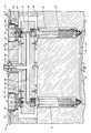
- FIG. 1is a cross-sectional side view of a preferred embodiment of the valve pin actuator as employed in an injection molding system
- FIG. 2is a top plan view of the valve pin actuator as taken along line 2 — 2 of FIG. 1;
- FIG. 3is an enlarged fragmentary cross-sectional side view of the assembly of FIGS. 1 and 2 as taken along line 3 — 3 of FIG. 2;
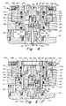
- FIG. 4is a somewhat schematic cross-sectional side view of the valve pin actuator similar to that illustrated in FIG. 3, but illustrating both fluid ports simultaneously and the piston in its “up” position;
- FIG. 5is also a somewhat schematic cross-sectional side view of the valve pin actuator as illustrated in FIG. 4, but with the piston shown in its “down” position;
- FIG. 6is an enlarged fragmentary cross-sectional side view of the valve pin actuator detailing the valve pin actuator as taken along line 6 — 6 of FIG. 4;
- FIG. 7is a cross-sectional plan view taken along line 7 — 7 of FIG. 5;
- FIG. 8is a somewhat schematic exploded cross-sectional side view showing removal of the clamping plate and actuator body without requiring the disconnection of any hydraulic hoses or the valve pin;
- FIG. 9is an exploded perspective view of the valve pin actuator showing the various components thereof.
- FIGS. 1-3illustrate an injection molding system 10 used to mold a plastic part.
- a mold part 12typically called a core block
- a mold part 14typically called a cavity block.
- the hot runner manifold 16Disposed over the upper mold part 14 is the hot runner manifold 16 .
- the hot runner manifold 16supports nozzles 18 , which are threadably screwed therein.
- a heater 20for maintaining the melt material passing through the nozzle at its process temperature.
- heat pipesmay be employed in the nozzle 18 , alone, or in conjunction with the band heaters 20 , such as illustrated in U.S. Pat. No. 4,389,002.
- a cavity 22that determines the contour of the molded part being produced. Also, as noted in particular in FIG. 3, at the end of the nozzle 18 , there is provided a nozzle tip 24 , disposed about a nozzle insert 26 .
- FIG. 3also illustrates the valve pin 28 in its closed position.
- the valve pin 28extends through a central bore in the nozzle 18 , and, in the embodiment illustrated, has a tapered end 30 that mates with a like tapered gate 32 in the mold.
- the inventionis not limited to a particular type of nozzle arrangement, as different tip and insert configurations are possible.
- the gatecould be formed in the tip, with the valve pin mating with the tapered surface of the tip.
- the valve pinwhen gating directly onto an angled part surface, the valve pin can be contoured to match the part.
- FIG. 1also illustrates the machine nozzle 34 of the injection molding machine that feeds the molten plastic material through a porting arrangement that extends through the top clamping plate 36 .
- This porting arrangementalso feeds through a bore 38 in the hot runner manifold 16 .
- the bore 38feeds each of the nozzles 18 .
- FIG. 1also illustrates spacers 42 for properly positioning the clamping plate 36 relative to the mold part 14 .
- the clamping plate 36is cooled as illustrated by the water channels 44 .
- a locating pin 46disposed between the manifold and the mold part.
- FIG. 1also illustrates a series of support pads 48 for providing proper distancing and positioning between the mold part 14 , the manifold 16 , and the cooled clamping plate 36 .
- the actuator assembly 52includes a cylinder 54 which is mounted in an accommodating aperture 55 in the clamping plate 36 . As illustrated, for example, in FIG. 3, this aperture is of a stepped configuration.
- the actuator assemblyalso includes a piston 56 supported within the cylinder 54 and held in place by a retainer 58 .
- FIGS. 8 and 9also illustrate other components which make up the valve pin assembly 70 , such as the actuator cap 60 , the pin head 62 , the actuator support 64 , and the locking screw 66 .
- the ring 68 and associated snap ring 69facilitate interconnection between the valve pin assembly 70 and the piston 56 .
- the valve actuator cylinder 54has two hydraulic lines 72 that connect thereto, as illustrated in FIG. 2 . These hydraulic lines provide pressurized fluid between the piston 56 and the cylinder 54 to facilitate movement of the piston within the cylinder. In this regard, refer to FIGS. 4 and 5. In FIGS. 4 and 5 it is noted that the hydraulic lines 72 are schematically shown on opposite sides of the cylinder 54 . In actuality, these lines are disposed as illustrated in FIG. 2, but for the sake of schematic explanation, they are illustrated on opposite sides of the cylinder in FIGS. 4 and 5 to more clearly describe the operation of the hydraulic circuit as it relates to operation of the actuator assembly 52 and valve pin assembly 70 .
- FIGS. 4 and 5the pressure is applied as indicated by arrows “a”.
- the pressureis input at the hydraulic line 72 a and in FIG. 5 an opposing pressure is illustrated at hydraulic line 72 b . These pressures correspond to the positioning of the valve pin.
- valve pin 28When hydraulic line 72 b is pressurized, as in FIG. 5, the valve pin 28 is held in its down position (as shown). The piston 56 is moved to its down position by means of hydraulic fluid entering the annular port 75 , and exerting pressure on annular flange 81 . In that position, the check pin 76 is in its lowermost position and seals off fluid flow to the lower part of the hydraulic circuit.
- valve pinmoves to the up position with hydraulic pressure being imposed at the port 77 against annular flange 83 of piston 56 to move the piston 56 in an upward direction.
- the check pin 76is in the “up” position and permits some fluid flow from the lower hydraulic circuit to the upper hydraulic circuit, as explained in greater detail hereinafter.
- the cylinder 54is positioned in a recess or aperture 55 that is machined in the top clamp plate 36 and is held in position by four mounting screws 79 , such as illustrated in FIGS. 2 and 3.
- the top of the cylinder 54is provided with two lift holds 84 . These lift holds enable the cylinder to be easily removed from the top clamp plate, when the screws 79 and the ring 69 are removed.
- the hydraulic lines 72are located within machined channels in the top clamp plate. These channels are typically terminated on one side of the top clamp plate (non-operator side) using quick disconnect fittings.
- the cylinder 54is in thermal contact with the top clamp plate as illustrated in FIG. 3 . This thermal contact is important so that the cylinder remains relatively cool.
- the temperature of the manifold 16is controlled to be at the plastic processing temperature (450° F.-550° F. typically). If the hydraulic cylinder gets too hot (greater than 400° F.) due to the manifold, there can be a degradation or damage of the O-rings 82 .
- the top clamp plateis provided with water cooling lines 44 machined through the top clamp plate.
- thermal contact between the valve cylinder 54 and the top clamp plate 36is important in preventing the valve cylinder from getting too hot.
- hydraulic lines 72With regard to the description hereinbefore, reference has been made to hydraulic lines 72 . However, the same principles also apply to the use of pneumatics instead of hydraulics. Typically, higher pressures are used in hydraulics such as 300-1500 p.s.i. Pneumatics are limited to plant supplied air pressure which is typically 85-100 p.s.i. Accordingly, a pneumatic actuator tends to be larger with increased piston area needed to generate forces equivalent to a hydraulic actuator.
- O-rings 82As described above, movement of the valve pin 28 is caused by the piston 56 moving vertically within the valve cylinder 54 when pressurized. As indicated previously, there are three O-rings 82 that are provided. These O-rings may be constructed of Viton. The O-rings 82 provide hydraulic fluid seals between the piston 56 and the cylinder 54 , as well as between the piston 56 and the retainer 58 . Furthermore, other seals such as cup seals may be used.
- the retainer 58is used to support the piston 56 within the cylinder 54 .
- the retainer 58also limits the travel of the piston in the downward direction such as is illustrated in FIG. 5 .
- the retaineris provided with a series of through holes and counter bores to receive the retainer screws 59 , as illustrated, for example, in FIGS. 3, 8 and 9 .
- one of the larger O-rings 82is disposed between the retainer 58 and the piston 56 . This provides a hydraulic seal with the piston.
- a second smaller O-ring 94is used to provide a hydraulic seal between the retainer 58 and the cylinder 54 .
- the valve pin assembly 70secures the valve pin 28 to the actuator and includes actuator cap 60 , actuator support 64 , pin head 62 , and locking screw 66 .
- the valve pin assembly 70is secured to the piston 56 primarily by means of the ring 68 and the associated snap ring 69 , as illustrated in FIG. 8 .
- the ring 68 and the snap ring 69provide a clamping action to secure the valve pin assembly 70 to the piston 56 .
- the actuator cap 60has a counter bore and a through hole to receive the locking screw 66 .
- the actuator cap 60is also internally threaded, such as illustrated in FIGS. 4-6, to receive the externally threaded pin head 62 .
- the actuator support 64has a base flange 65 that is used to mount the actuator support directly to the hot runner manifold 16 . For providing this mounting, there are provided mounting screws 67 .
- the actuator support 64is preferably constructed of a material of low thermal conductivity such as titanium or stainless steel to increase the thermal gradient between the manifold 16 and the actuator assembly 52 .
- the actuator support 64has a horizontal through hole to receive a relatively large dowel 85 . Also, additional through holes 86 are provided to allow any plastic that may leak from the valve pin bushing 102 into the actuator support to flow out of the part without creating a high pressure.
- the pin head 62is used to retain the valve pin 28 .
- the pin head 62is provided with external threads to hold the pin head to the actuator cap 60 .
- the pin head 62has a central bore that is threaded to receive the end of the locking screw 66 . See, for example, FIGS. 6 and 8.
- the pin head 62is also provided with a transverse slot 87 to receive the large dowel 85 , as illustrated in FIG. 9 .
- the vertical slot 87allows the valve pin assembly 70 to move vertically relative to the dowel.
- the vertical slot 87 and the dowel 85serve to prevent rotation of the valve pin assembly and maintain angular alignment of the valve pin relative to the gate 32 .
- the pin head 62has a central hole for receiving the top of the valve pin and also has two horizontal holes as illustrated in FIG. 9, for receiving the pair of dowel pins 90 .
- FIG. 9also shows corresponding slots 92 at the top of the valve pin 28 for receiving the dowel pins 90 .
- the two dowel pins 90are used to hold the valve pin 28 with respect to the pin head 62 while preventing rotation of the valve pin.
- the larger dowel 85is used to prevent rotation of the valve pin assembly 70 .
- the lock screw 66when tightened, insures that the pin head 62 does not rotate with respect to the actuator cap 60 .
- a bushing nut 100Associated with the hot runner manifold 16 is a bushing nut 100 , as illustrated, for example, in FIG. 8 .
- the bushing nuthas external threads as illustrated for engagement into the hot runner manifold 16 .
- the bushing nutserves to retain the valve pin bushing 102 in position without exerting any axial stresses that can cause binding of the valve pin 28 .
- the valve pin bushing 102provides a guide for the valve pin 28 . Using tight tolerances, a plastic seal is created between the valve pin 28 and the valve pin bushing 102 .
- the bottom surface of the valve pin bushing 102provides a seal between the manifold 16 and the bushing 102 to prevent plastic leakage.
- the check pin 76is positioned, such as illustrated in FIGS. 4 and 5, in a bore in the cylinder 54 .
- the boreis dimensioned so as to provide for a small amount of hydraulic fluid flow between the two hydraulic ports. A small gap between the check pin and the bore will limit the flow substantially. The flow is unidirectional.
- the check pinWhen the check pin is in the “up” position, as in FIG. 4, a flow about the pin is allowed.
- the check pinWhen the check pin is in the “down” position as illustrated in FIG. 5, the check pin seals against a taper at the bottom of the bore. The purpose of the flow is to allow any air that may otherwise be trapped in the hydraulic lines to be bled out of the lines.
- the hydraulic circuit of the actuator assembly 52also includes metal expansion plugs 108 that are used to cap the ends of the bores in the cylinder used for hydraulic fluid flow, such plugs as Lee or CV plugs may be used.
- FIGS. 4-6show that the valve pin assembly 70 is supported in a manner that would allow some limited side-to-side motion in any direction thereof as the hot runner manifold undergoes certain expansion such as might be indicated by the arrow B in FIG. 3 .
- Thisis facilitated by the interaction of the ring 68 , actuator cap 60 and the annular flange 110 extending inwardly of the piston 56 .
- the flange and pistoncan move side to side within the clearance 103 that is formed between the actuator cap 60 and the flange 110 .
- This clearanceallows for relative expansion between the hot runner manifold 16 and the top clamp plate 36 essentially in any direction without putting a significant side load force on the valve pin 28 .
- the piston 56includes a plating thereon, such as chrome. This plating adds lubricity and insures slippage between the piston 56 and the actuator cap 60 during heat up or cool down of the manifold.
- check pin designprovides for a small flow of hydraulic fluid about the check pin 76 .
- prior designsrequired two additional hydraulic ports for bleed lines. That doubled the number of lines needed to be run in the top clamp plate.
- valve pin adjustmentis necessary so that the pin can be positioned to seat at a precise location in the gate, to eliminate vestige on the molded part.
Landscapes
- Engineering & Computer Science (AREA)
- Manufacturing & Machinery (AREA)
- Mechanical Engineering (AREA)
- Moulds For Moulding Plastics Or The Like (AREA)
Abstract
Description
Claims (16)
Priority Applications (2)
| Application Number | Priority Date | Filing Date | Title |
|---|---|---|---|
| US10/144,480US6599116B2 (en) | 1997-06-13 | 2002-05-13 | Valve pin actuator |
| US10/403,833US20040047935A1 (en) | 1998-04-21 | 2003-03-31 | Apparatus and method for simulating an injection molding process |
Applications Claiming Priority (3)
| Application Number | Priority Date | Filing Date | Title |
|---|---|---|---|
| US08/874,962US5894025A (en) | 1997-06-13 | 1997-06-13 | Valve pin actuator |
| US09/185,365US6419870B1 (en) | 1997-06-13 | 1998-11-03 | Valve pin actuator |
| US10/144,480US6599116B2 (en) | 1997-06-13 | 2002-05-13 | Valve pin actuator |
Related Parent Applications (1)
| Application Number | Title | Priority Date | Filing Date |
|---|---|---|---|
| US09/185,365DivisionUS6419870B1 (en) | 1997-06-13 | 1998-11-03 | Valve pin actuator |
Related Child Applications (1)
| Application Number | Title | Priority Date | Filing Date |
|---|---|---|---|
| US10/403,833Continuation-In-PartUS20040047935A1 (en) | 1998-04-21 | 2003-03-31 | Apparatus and method for simulating an injection molding process |
Publications (2)
| Publication Number | Publication Date |
|---|---|
| US20020132025A1 US20020132025A1 (en) | 2002-09-19 |
| US6599116B2true US6599116B2 (en) | 2003-07-29 |
Family
ID=25364971
Family Applications (3)
| Application Number | Title | Priority Date | Filing Date |
|---|---|---|---|
| US08/874,962Expired - LifetimeUS5894025A (en) | 1997-06-13 | 1997-06-13 | Valve pin actuator |
| US09/185,365Expired - LifetimeUS6419870B1 (en) | 1997-06-13 | 1998-11-03 | Valve pin actuator |
| US10/144,480Expired - LifetimeUS6599116B2 (en) | 1997-06-13 | 2002-05-13 | Valve pin actuator |
Family Applications Before (2)
| Application Number | Title | Priority Date | Filing Date |
|---|---|---|---|
| US08/874,962Expired - LifetimeUS5894025A (en) | 1997-06-13 | 1997-06-13 | Valve pin actuator |
| US09/185,365Expired - LifetimeUS6419870B1 (en) | 1997-06-13 | 1998-11-03 | Valve pin actuator |
Country Status (4)
| Country | Link |
|---|---|
| US (3) | US5894025A (en) |
| EP (1) | EP0988139A1 (en) |
| CA (1) | CA2293662A1 (en) |
| WO (1) | WO1998056560A1 (en) |
Cited By (47)
| Publication number | Priority date | Publication date | Assignee | Title |
|---|---|---|---|---|
| US20050233028A1 (en)* | 2003-09-12 | 2005-10-20 | Injectnotech Inc. | Injection molding valve gate system and activating mechanism |
| US20050255187A1 (en)* | 2004-05-14 | 2005-11-17 | University Of Massachusetts | Methods and devices for melt pressure regulation |
| US20070237852A1 (en)* | 2006-04-11 | 2007-10-11 | Filippo Martino | Easily removable valve pin bushing |
| US20090117219A1 (en)* | 2005-04-07 | 2009-05-07 | Jonathon Fischer | Configurable Manifold |
| WO2009120534A3 (en)* | 2008-03-24 | 2010-03-18 | Husky Injection Molding Systems Ltd | Safety connector for hot runner, having latch destructively interlocking valve stem with actuation plate |
| US8091202B2 (en) | 2009-05-06 | 2012-01-10 | Synventive Molding Solutions, Inc. | Method and apparatus for coupling and uncoupling an injection valve pin |
| US20120119400A1 (en)* | 2010-03-30 | 2012-05-17 | Panos Trakas | Valve gate system |
| US20120231111A1 (en)* | 2010-09-10 | 2012-09-13 | Mold-Masters (2007) Limited | Valve Pin for Accommodating Side Loading |
| US20120231108A1 (en)* | 2010-03-25 | 2012-09-13 | Synventive Molding Sulutions, Inc. | Actuator mount system |
| US20140037782A1 (en)* | 2010-06-24 | 2014-02-06 | Sacmi Cooperativa Meccanici Imola Societa' Cooperative | Injection system |
| WO2014134376A1 (en) | 2013-02-28 | 2014-09-04 | Synventive Molding Solutions, Inc. | Fast acting reduced velocity pin control |
| WO2015066004A1 (en) | 2013-10-28 | 2015-05-07 | Synventive Molding Solutions, Inc. | Reduced velocity control based on sensed system condition |
| WO2015105777A1 (en) | 2014-01-08 | 2015-07-16 | Synventive Molding Solutions, Inc. | Valve pin and nozzle configuration and method of control |
| WO2015108895A1 (en) | 2014-01-15 | 2015-07-23 | Synventive Molding Solutions, Inc. | Two material injection molding apparatus component and additive manufacturing process therefor |
| US9321205B2 (en) | 2012-09-26 | 2016-04-26 | Synventive Molding Solutions, Inc. | Valve pin rotation limiter |
| WO2016137744A1 (en)* | 2015-02-23 | 2016-09-01 | Husky Injection Molding Systems Ltd. | Melt dispensing apparatus with adjustable stop |
| WO2016153703A1 (en) | 2015-03-20 | 2016-09-29 | Synventive Molding Solutions, Inc. | Actuator cooling apparatus and method |
| US9556888B2 (en) | 2012-05-24 | 2017-01-31 | Parker-Hannifin Corporation | Face mount interface for an electro-hydraulic actuator |
| WO2017066283A1 (en) | 2015-10-13 | 2017-04-20 | Synventive Molding Solutions, Inc. | Valve monitoring method and apparatus |
| WO2017200517A1 (en) | 2016-05-16 | 2017-11-23 | Synventive Molding Solutions, Inc. | Position detector |
| WO2017210169A1 (en) | 2016-06-01 | 2017-12-07 | Synventive Molding Solutions, Inc. | Controller arrangement for injection molding system |
| WO2017214387A1 (en) | 2016-06-09 | 2017-12-14 | Synventive Molding Solutions, Inc. | Cable transmission of actuator control for injection molding system |
| WO2018017807A2 (en) | 2016-07-20 | 2018-01-25 | Synventive Molding Solutions, Inc. | Injection molding apparatus and method for automatic cycle to cycle cavity injection |
| EP3299140A1 (en) | 2013-06-24 | 2018-03-28 | Synventive Molding Solutions, Inc. | Injection molding flow control apparatus and method |
| WO2018089243A1 (en) | 2016-11-14 | 2018-05-17 | Synventive Molding Solutions, Inc. | Actuator cooling apparatus and method |
| EP3335854A1 (en) | 2013-08-26 | 2018-06-20 | Synventive Molding Solutions, Inc. | Actuator system for rotating valve pin |
| WO2018148407A1 (en) | 2017-02-08 | 2018-08-16 | Synventive Molding Solutions, Inc. | Apparatus and method for controlling injection molding |
| WO2018169819A1 (en) | 2017-03-16 | 2018-09-20 | Synventive Molding Solutions, Inc. | Injection molding apparatus |
| WO2018175362A1 (en) | 2017-03-20 | 2018-09-27 | Synventive Molding Solutions, Inc. | Valve pin positions and velocity control method and apparatus |
| WO2018183810A1 (en) | 2017-03-31 | 2018-10-04 | Synventive Molding Solutions, Inc. | Rotary valve |
| WO2018194961A1 (en) | 2017-04-18 | 2018-10-25 | Synventive Molding Solutions, Inc. | Linear to linear valve pin drive during injection cycle |
| WO2018200660A1 (en) | 2017-04-26 | 2018-11-01 | Synventive Molding Solutions, Inc. | Double seal valve pin tip with vent |
| US10267429B2 (en) | 2015-10-23 | 2019-04-23 | Magna Exteriors Inc. | Plastic injection mold—SVG actuator—internal seal upgrade |
| WO2019100085A1 (en) | 2017-11-14 | 2019-05-23 | Synventive Molding Solutions, Inc. | Actuator with eccentric pin drive |
| WO2020068285A1 (en) | 2018-08-17 | 2020-04-02 | Synventive Molding Solutions, Inc. | Disrupted flow through injection molding flow channel |
| WO2020176479A1 (en) | 2019-02-25 | 2020-09-03 | Synventive Molding Solutions, Inc. | Cooled electric actuator controlled injection |
| WO2020204980A1 (en) | 2019-04-02 | 2020-10-08 | Synventive Molding Solutions, Inc. | Nozzle heater |
| US10843395B2 (en) | 2017-11-21 | 2020-11-24 | Gateway Plastics, Inc. | Multi-layer injection molded container |
| WO2020242510A1 (en) | 2019-05-28 | 2020-12-03 | Synventive Molding Solutions, Inc. | Partially rotated eccentric drive for valve pin |
| WO2021034793A1 (en) | 2019-08-20 | 2021-02-25 | Synventive Molding Solutions, Inc. | Injection molding apparatus with integrated actuator electronic drive |
| WO2021080767A1 (en) | 2019-10-21 | 2021-04-29 | Synventive Molding Solutions, Inc. | Electric actuator drive for injection molding flow control |
| WO2021168391A1 (en) | 2020-02-20 | 2021-08-26 | Synventive Molding Solutions, Inc. | Sequential injection to multiple mold cavities |
| WO2022005530A1 (en) | 2020-07-01 | 2022-01-06 | Synventive Molding Solutions, Inc. | Method and apparatus for controlled injection fluid flow |
| US11254038B2 (en) | 2017-07-07 | 2022-02-22 | Thermoplay S.P.A. | Injection unit, with closure pin, for the injection moulding of plastic material, with capacity to recover thermal dilatations and avoid leakage of the plastic material |
| WO2022076782A1 (en) | 2020-10-09 | 2022-04-14 | Synventive Molding Solutions, Inc. | Spring cushioned valve pin |
| WO2022125608A1 (en) | 2020-12-08 | 2022-06-16 | Synventive Molding Solutions, Inc. | Injection molding apparatus with cooled integrated actuator electronic drive |
| US11920689B2 (en) | 2022-01-11 | 2024-03-05 | Samsung Electronics Co., Ltd. | Loose type pneumatic valve and loose type pneumatic valve module including the same |
Families Citing this family (63)
| Publication number | Priority date | Publication date | Assignee | Title |
|---|---|---|---|---|
| US6464909B1 (en)* | 1998-04-21 | 2002-10-15 | Synventive Molding Solutions, Inc. | Manifold system having flow control |
| US6294122B1 (en) | 1998-06-26 | 2001-09-25 | Synventive Molding Solutions, Inc. | Electric actuator for a melt flow control pin |
| US6632079B1 (en) | 1998-04-21 | 2003-10-14 | Synventive Molding Solutions, Inc. | Dynamic feed control system |
| US6361300B1 (en) | 1998-04-21 | 2002-03-26 | Synventive Molding Solutions, Inc. | Manifold system having flow control |
| US6309208B1 (en) | 1997-06-13 | 2001-10-30 | Synventive Molding Solutions, Inc. | Apparatus for proportionally controlling fluid delivery to a mold |
| US6585505B2 (en) | 1998-04-21 | 2003-07-01 | Synventive Molding Solutions, Inc. | Machine for proportionally controlling fluid delivery to a mold |
| US20020121713A1 (en)* | 1997-06-13 | 2002-09-05 | Mark Moss | Apparatus and method for proportionally controlling fluid delivery to stacked molds |
| US6514440B1 (en) | 1998-04-21 | 2003-02-04 | Synventive Molding Solutions, Inc. | Apparatus and method for purging injection molding system |
| US5894025A (en) | 1997-06-13 | 1999-04-13 | Kona Corporation | Valve pin actuator |
| US6638049B1 (en) | 1997-06-13 | 2003-10-28 | Synventive Molding Solutions, Inc. | Apparatus and method for proportionally controlling fluid delivery to readily replaceable mold inserts |
| US6287107B1 (en) | 1997-09-02 | 2001-09-11 | Synventive Molding Solutions, Inc. | Apparatus for proportionally controlling fluid delivery to a mold |
| US20020086086A1 (en)* | 1999-09-21 | 2002-07-04 | Mark Doyle | Curvilinear valve pin controller for injection molding |
| US6824379B2 (en)* | 1998-04-21 | 2004-11-30 | Synventive Molding Solutions, Inc. | Apparatus for utilizing an actuator for flow control valve gates |
| US20040047935A1 (en)* | 1998-04-21 | 2004-03-11 | Synventive Molding Solutions, Inc. | Apparatus and method for simulating an injection molding process |
| US7234929B2 (en)* | 1999-09-21 | 2007-06-26 | Synventive Molding Solutions, Inc. | Injection molding flow control apparatus and method |
| US6589039B1 (en) | 1998-04-21 | 2003-07-08 | Synventive Molding Solutions, Inc. | Controlled injection using manifold having multiple feed channels |
| US6261084B1 (en) | 1998-08-28 | 2001-07-17 | Synventive Moldings Solutions Canada, Inc. | Elastically deformable nozzle for injection molding |
| IT1308036B1 (en)* | 1999-05-21 | 2001-11-29 | Thermolpay S R L | STEM DRIVE GROUP OF A SHUTTER IN A MOLD FOR INJECTION MOLDING OF PLASTIC MATERIALS |
| US6769901B2 (en)* | 2000-04-12 | 2004-08-03 | Mold-Masters Limited | Injection nozzle system for an injection molding machine |
| EP1223019B1 (en)* | 2001-01-10 | 2005-05-25 | Synventive Molding Solutions B.V. | Actuating cylinder for a valve gated injection moulding device |
| DE60107528T2 (en)* | 2001-01-10 | 2005-04-07 | Synventive Molding Solutions B.V. | Injection molding device with position indicator for a needle |
| CA2358148A1 (en)* | 2001-10-03 | 2003-04-03 | Mold-Masters Limited | A nozzle |
| CA2358187A1 (en)* | 2001-10-03 | 2003-04-03 | Mold-Masters Limited | Nozzle seal |
| US6962492B2 (en)* | 2001-10-05 | 2005-11-08 | Mold-Masters Limited | Gap seal between nozzle components |
| US6840758B2 (en)* | 2001-10-26 | 2005-01-11 | Mold-Masters Limited | Valve bushing assembly |
| AU2002359849A1 (en)* | 2001-12-26 | 2003-07-24 | Synventive Molding Solutions, Inc. | Non-coaxial injection molding valve flow control |
| US20030143298A1 (en)* | 2002-01-30 | 2003-07-31 | Blais Paul R. | Injection molding nozzle |
| US7128566B2 (en)* | 2002-02-21 | 2006-10-31 | Mold-Masters Limited | Valve pin guiding tip for a nozzle |
| US7014455B2 (en) | 2002-03-14 | 2006-03-21 | Mold-Masters Limited | Valve-gated injection molding system with side-mounted actuator |
| US6683283B2 (en) | 2002-05-10 | 2004-01-27 | Dynisco Hot Runners Inc. Canada | Apparatus and method for heating injection molding fluid |
| CN100448646C (en)* | 2002-07-30 | 2009-01-07 | 标准模具(2007)有限公司 | Valve pin guidance and alignment system for hot runner in injection molding apparatus |
| CA2437076C (en)* | 2002-08-14 | 2010-10-12 | Mold-Masters Limited | Valve pin adjustment device |
| CA2409785C (en) | 2002-10-25 | 2010-09-07 | Harald Schmidt | Apparatus for heating injection molding fluid |
| DE10354456B4 (en)* | 2002-11-21 | 2016-10-13 | Mold-Masters (2007) Limited | Nozzle having a tip, a part surrounding the tip and a positioning part and injection molding device with the nozzle |
| CA2452112A1 (en)* | 2002-12-09 | 2004-06-09 | Mold-Masters Limited | Nozzle tip and seal |
| EP1648681B1 (en)* | 2003-06-23 | 2010-11-03 | Panos Trakas | Improved adjustable valve pin assembly and method |
| GB0328467D0 (en)* | 2003-12-09 | 2004-01-14 | Harper Alan R | Cocomposite production by resin transfer moulding |
| US7160100B2 (en) | 2004-01-06 | 2007-01-09 | Mold-Masters Limited | Injection molding apparatus having an elongated nozzle incorporating multiple nozzle bodies in tandem |
| CA2482254A1 (en)* | 2004-04-07 | 2005-10-07 | Mold-Masters Limited | Modular injection nozzle having a thermal barrier |
| US7406874B2 (en)* | 2004-04-28 | 2008-08-05 | Black & Decker Inc. | Corrosion fuse |
| DE202004019328U1 (en)* | 2004-10-20 | 2005-02-24 | Mold-Masters Ltd., Georgetown | Needle valve nozzle for injection molding plastics has a mechanism to prevent needle rotation during needle adjustment |
| US7320588B2 (en)* | 2005-10-12 | 2008-01-22 | Mold-Masters (2007) Limited | Distribution assembly for an injection molding apparatus |
| US20070119504A1 (en)* | 2005-11-28 | 2007-05-31 | Yudo Co. Ltd. | Heat dissipating apparatus for cylinders of injection molding machines |
| US8186994B2 (en)* | 2006-06-14 | 2012-05-29 | Cerniglia Anthony J | Sucker pin bushing |
| KR100860139B1 (en) | 2007-02-28 | 2008-09-25 | 김혁중 | Hot runner valve device for injection molding machine |
| US7722351B2 (en)* | 2007-10-22 | 2010-05-25 | Mold-Masters (2007) Limited | Injection molding apparatus having magnetic valve pin coupling |
| WO2009158091A1 (en)* | 2008-06-25 | 2009-12-30 | Husky Injection Molding Systems Ltd | Back-up device for use in a melt distribution apparatus of an injection molding system |
| EP2398631B1 (en)* | 2009-01-22 | 2016-06-08 | Mold-Masters (2007) Limited | Injection molding apparatus |
| IT1397127B1 (en)* | 2009-12-02 | 2013-01-04 | Thermoplay Spa | SHUTTER ASSEMBLY, FOR PLASTIC MATERIAL INJECTION UNIT, WITH MICROMETRIC ADJUSTMENT OF THE OPTURAL STEM, AND CORRESPONDING TO DEVICE MICROMETRICALLY AND FIX A THREADED ELEMENT. |
| IT1400952B1 (en)* | 2010-07-20 | 2013-07-05 | Thermoplay Spa | IMPROVED FILLING UNIT, WITH MULTI-STEM CONTROL, FOR INJECTION MOLDING OF PLASTIC MATERIAL |
| US9498909B2 (en) | 2011-11-23 | 2016-11-22 | Synventive Molding Solutions, Inc. | Injection molding flow control apparatus and method |
| CA2822458A1 (en)* | 2011-01-26 | 2012-08-02 | Husky Injection Molding Systems Ltd. | Valve-stem assembly removable from runner system while valve-actuator assembly remains connected with manifold assembly |
| EP2675603B1 (en)* | 2011-02-17 | 2016-10-26 | Husky Injection Molding Systems Ltd. | Mold-tool system including runner assembly configured to provide access portal for permitting access to assembly |
| US20130147091A1 (en)* | 2011-12-12 | 2013-06-13 | Mold-Masters (2007) Limited | Valve pin actuator |
| EP3003680B1 (en) | 2013-05-28 | 2018-04-04 | Synventive Molding Solutions, Inc. | End of stroke actuator bleed |
| CA2949272C (en)* | 2014-06-30 | 2019-03-19 | Husky Injection Molding Systems Ltd. | Spring retaining pin for valve stem retention |
| WO2017027192A1 (en)* | 2015-08-10 | 2017-02-16 | Synventive Molding Solutions, Inc. | Actuator apparatus and method enabling multiple piston velocities |
| US10792772B2 (en) | 2018-07-17 | 2020-10-06 | Denso International America, Inc. | Heat exchanger replacement mounting pin and drill jig |
| US11396118B2 (en)* | 2019-09-23 | 2022-07-26 | Incoe Corporation | Actuator for controlling multiple injection molding valve pins |
| CN110561685B (en)* | 2019-10-16 | 2024-10-15 | 江苏铁锚玻璃股份有限公司 | Edge wrapping device and edge wrapping method applied to glass |
| KR20220062965A (en)* | 2020-11-09 | 2022-05-17 | 삼성전자주식회사 | Valve pin and hot runner system threrwith |
| EP4255711A4 (en)* | 2020-12-04 | 2024-11-27 | Mold-Masters (2007) Limited | HOT RUNNER SYSTEM |
| IT202200017373A1 (en)* | 2022-08-17 | 2024-02-17 | Inglass Spa | “Injection molding apparatus” |
Citations (26)
| Publication number | Priority date | Publication date | Assignee | Title |
|---|---|---|---|---|
| US4389002A (en) | 1980-02-07 | 1983-06-21 | Kona Corporation | Injection molding nozzle |
| US4468191A (en) | 1983-03-24 | 1984-08-28 | Gellert Jobst U | Hydraulically actuated injection molding system with alternate hydraulic connections |
| US4500279A (en) | 1983-07-06 | 1985-02-19 | Kona Corporation | Heat pipe manifold system |
| DE3336203A1 (en) | 1983-10-05 | 1985-04-18 | HASCO-Normalien Hasenclever & Co, 5880 Lüdenscheid | Injection or compression mould for processing plastics materials |
| US4521179A (en) | 1983-02-24 | 1985-06-04 | Gellert Jobst U | Injection molding core ring gate system |
| US4698013A (en) | 1986-10-20 | 1987-10-06 | Butcher Robert M | Mechanism for valve gated injection molding with resilient retaining ring |
| US4705473A (en) | 1986-10-23 | 1987-11-10 | Mold-Masters Limited | Dual feed bushing for multi-cavity injection molding |
| US5160746A (en) | 1989-06-07 | 1992-11-03 | Kimberly-Clark Corporation | Apparatus for forming a nonwoven web |
| EP0635350A1 (en) | 1993-07-20 | 1995-01-25 | Incoe Corporation | Pneumatic control device for hot runner needle valves for injection moulds |
| US5492467A (en) | 1993-12-30 | 1996-02-20 | Kona Corporation | Apparatus for injection molding articles of amorphous polyethylene terephthalate |
| US5545028A (en) | 1994-08-16 | 1996-08-13 | Kona Corporation | Bushing tip for injection molding apparatus |
| US5554395A (en) | 1993-08-12 | 1996-09-10 | Kona Corporation | Open bore injection molding apparatus |
| US5635227A (en) | 1995-06-07 | 1997-06-03 | R & D Tool And Engineering, Inc. | Replaceable air cylinder unit and valve gate for injection molding machines |
| US5820803A (en) | 1995-10-31 | 1998-10-13 | Takaoka Seiko Co., Ltd. | Valve gate-type injection molding method and apparatus therefor |
| US5871786A (en) | 1997-04-04 | 1999-02-16 | Kona Corporation | Tip heated hot runner nozzle |
| US5885628A (en) | 1993-08-12 | 1999-03-23 | Dynisco, Inc. | Injection molding nozzle |
| US5894025A (en) | 1997-06-13 | 1999-04-13 | Kona Corporation | Valve pin actuator |
| US5916605A (en) | 1996-09-27 | 1999-06-29 | Dynisco Hotrunners, Inc. | Valve actuated injection molding apparatus |
| US5948448A (en) | 1997-11-18 | 1999-09-07 | Eurotool, Inc. | Apparatus for controlling plastic melt flow in injection molding machines |
| US6062840A (en) | 1997-09-02 | 2000-05-16 | Dynisco Hotrunners, Inc. | Hot runner system for coinjection molding |
| US6254377B1 (en) | 1998-04-21 | 2001-07-03 | Synventive Molding Solutions, Inc. | Manifold system having flow control using extended valve pin |
| US6261084B1 (en) | 1998-08-28 | 2001-07-17 | Synventive Moldings Solutions Canada, Inc. | Elastically deformable nozzle for injection molding |
| US6287107B1 (en) | 1997-09-02 | 2001-09-11 | Synventive Molding Solutions, Inc. | Apparatus for proportionally controlling fluid delivery to a mold |
| US6294122B1 (en) | 1998-06-26 | 2001-09-25 | Synventive Molding Solutions, Inc. | Electric actuator for a melt flow control pin |
| US6309208B1 (en) | 1997-06-13 | 2001-10-30 | Synventive Molding Solutions, Inc. | Apparatus for proportionally controlling fluid delivery to a mold |
| US6464909B1 (en) | 1998-04-21 | 2002-10-15 | Synventive Molding Solutions, Inc. | Manifold system having flow control |
- 1997
- 1997-06-13USUS08/874,962patent/US5894025A/ennot_activeExpired - Lifetime
- 1998
- 1998-05-27WOPCT/US1998/010713patent/WO1998056560A1/ennot_activeApplication Discontinuation
- 1998-05-27CACA002293662Apatent/CA2293662A1/ennot_activeAbandoned
- 1998-05-27EPEP98924899Apatent/EP0988139A1/ennot_activeWithdrawn
- 1998-11-03USUS09/185,365patent/US6419870B1/ennot_activeExpired - Lifetime
- 2002
- 2002-05-13USUS10/144,480patent/US6599116B2/ennot_activeExpired - Lifetime
Patent Citations (36)
| Publication number | Priority date | Publication date | Assignee | Title |
|---|---|---|---|---|
| US4389002A (en) | 1980-02-07 | 1983-06-21 | Kona Corporation | Injection molding nozzle |
| US4521179A (en) | 1983-02-24 | 1985-06-04 | Gellert Jobst U | Injection molding core ring gate system |
| US4468191A (en) | 1983-03-24 | 1984-08-28 | Gellert Jobst U | Hydraulically actuated injection molding system with alternate hydraulic connections |
| US4500279A (en) | 1983-07-06 | 1985-02-19 | Kona Corporation | Heat pipe manifold system |
| DE3336203A1 (en) | 1983-10-05 | 1985-04-18 | HASCO-Normalien Hasenclever & Co, 5880 Lüdenscheid | Injection or compression mould for processing plastics materials |
| US4698013A (en) | 1986-10-20 | 1987-10-06 | Butcher Robert M | Mechanism for valve gated injection molding with resilient retaining ring |
| US4705473A (en) | 1986-10-23 | 1987-11-10 | Mold-Masters Limited | Dual feed bushing for multi-cavity injection molding |
| US5160746A (en) | 1989-06-07 | 1992-11-03 | Kimberly-Clark Corporation | Apparatus for forming a nonwoven web |
| US5660369A (en) | 1993-07-09 | 1997-08-26 | Incoe Corporation | Pneumatic control device for needle valves in injection molding systems |
| EP0635350A1 (en) | 1993-07-20 | 1995-01-25 | Incoe Corporation | Pneumatic control device for hot runner needle valves for injection moulds |
| US5980237A (en) | 1993-08-12 | 1999-11-09 | Dynisco, Inc. | Injection molding nozzle |
| US5554395A (en) | 1993-08-12 | 1996-09-10 | Kona Corporation | Open bore injection molding apparatus |
| US5885628A (en) | 1993-08-12 | 1999-03-23 | Dynisco, Inc. | Injection molding nozzle |
| US5492467A (en) | 1993-12-30 | 1996-02-20 | Kona Corporation | Apparatus for injection molding articles of amorphous polyethylene terephthalate |
| US5674439A (en) | 1993-12-30 | 1997-10-07 | Kona Corporation | System and apparatus for injection molding articles of amorphous polyethylene terephthalate and similar materials |
| US5545028A (en) | 1994-08-16 | 1996-08-13 | Kona Corporation | Bushing tip for injection molding apparatus |
| US5635227A (en) | 1995-06-07 | 1997-06-03 | R & D Tool And Engineering, Inc. | Replaceable air cylinder unit and valve gate for injection molding machines |
| US5820803A (en) | 1995-10-31 | 1998-10-13 | Takaoka Seiko Co., Ltd. | Valve gate-type injection molding method and apparatus therefor |
| US5916605A (en) | 1996-09-27 | 1999-06-29 | Dynisco Hotrunners, Inc. | Valve actuated injection molding apparatus |
| US5948450A (en) | 1996-09-27 | 1999-09-07 | Dynisco Hotrunners, Inc. | Valve actuated injection molding apparatus |
| US5871786A (en) | 1997-04-04 | 1999-02-16 | Kona Corporation | Tip heated hot runner nozzle |
| US5894025A (en) | 1997-06-13 | 1999-04-13 | Kona Corporation | Valve pin actuator |
| US6309208B1 (en) | 1997-06-13 | 2001-10-30 | Synventive Molding Solutions, Inc. | Apparatus for proportionally controlling fluid delivery to a mold |
| US6419870B1 (en) | 1997-06-13 | 2002-07-16 | Synventive Molding Solutions, Inc. | Valve pin actuator |
| US6062840A (en) | 1997-09-02 | 2000-05-16 | Dynisco Hotrunners, Inc. | Hot runner system for coinjection molding |
| US6261075B1 (en) | 1997-09-02 | 2001-07-17 | Synventive Molding Solutions, Inc. | Hot runner system for coinjection molding |
| US6287107B1 (en) | 1997-09-02 | 2001-09-11 | Synventive Molding Solutions, Inc. | Apparatus for proportionally controlling fluid delivery to a mold |
| US5948448A (en) | 1997-11-18 | 1999-09-07 | Eurotool, Inc. | Apparatus for controlling plastic melt flow in injection molding machines |
| US6436320B1 (en) | 1998-04-21 | 2002-08-20 | Synventive Molding Solutions, Inc. | Method using manifold system having flow control |
| US6254377B1 (en) | 1998-04-21 | 2001-07-03 | Synventive Molding Solutions, Inc. | Manifold system having flow control using extended valve pin |
| US6464909B1 (en) | 1998-04-21 | 2002-10-15 | Synventive Molding Solutions, Inc. | Manifold system having flow control |
| US6343921B1 (en) | 1998-04-21 | 2002-02-05 | Synventive Molding Solutions | Manifold system having flow control using separate cavities |
| US6343922B1 (en) | 1998-04-21 | 2002-02-05 | Synventive Molding Solutions | Manifold system having flow control using pressure transducers |
| US6361300B1 (en) | 1998-04-21 | 2002-03-26 | Synventive Molding Solutions, Inc. | Manifold system having flow control |
| US6294122B1 (en) | 1998-06-26 | 2001-09-25 | Synventive Molding Solutions, Inc. | Electric actuator for a melt flow control pin |
| US6261084B1 (en) | 1998-08-28 | 2001-07-17 | Synventive Moldings Solutions Canada, Inc. | Elastically deformable nozzle for injection molding |
Non-Patent Citations (2)
| Title |
|---|
| "KONA HYD-4 Valve Gate Actuator", DFWG No. 47-18-101, Rev. 3. |
| "T-10VG Installation and Seal Ring Details", DWG No. T10VG-001, Rev. 4. |
Cited By (71)
| Publication number | Priority date | Publication date | Assignee | Title |
|---|---|---|---|---|
| US7452201B2 (en) | 2003-09-12 | 2008-11-18 | Injectnotech Inc. | Injection molding valve gate system and activating mechanism |
| US20050233028A1 (en)* | 2003-09-12 | 2005-10-20 | Injectnotech Inc. | Injection molding valve gate system and activating mechanism |
| US20050255187A1 (en)* | 2004-05-14 | 2005-11-17 | University Of Massachusetts | Methods and devices for melt pressure regulation |
| US20090117219A1 (en)* | 2005-04-07 | 2009-05-07 | Jonathon Fischer | Configurable Manifold |
| US7802983B2 (en) | 2005-04-07 | 2010-09-28 | Mold-Masters (2007) Limited | Configurable manifold |
| US20110008480A1 (en)* | 2005-04-07 | 2011-01-13 | Mold-Masters (2007) Limited | Configurable Manifold |
| US20070237852A1 (en)* | 2006-04-11 | 2007-10-11 | Filippo Martino | Easily removable valve pin bushing |
| US7862329B2 (en)* | 2006-04-11 | 2011-01-04 | Stacktech Systems, Ltd. | Easily removable valve pin bushing |
| US8282870B2 (en) | 2008-03-24 | 2012-10-09 | Husky Injection Molding Systems Ltd. | Safety connector for hot runner, having latch destructively interlocking valve stem with actuation plate |
| WO2009120534A3 (en)* | 2008-03-24 | 2010-03-18 | Husky Injection Molding Systems Ltd | Safety connector for hot runner, having latch destructively interlocking valve stem with actuation plate |
| US20110018172A1 (en)* | 2008-03-24 | 2011-01-27 | Husky Injection Molding Systems Ltd. | Safety connector for hot runner, having latch destructively interlocking valve stem with actuation plate |
| US8282388B2 (en) | 2009-05-06 | 2012-10-09 | Synventive Molding Solutions, Inc. | Apparatus for coupling and uncoupling an injection valve pin |
| US8091202B2 (en) | 2009-05-06 | 2012-01-10 | Synventive Molding Solutions, Inc. | Method and apparatus for coupling and uncoupling an injection valve pin |
| US20120231108A1 (en)* | 2010-03-25 | 2012-09-13 | Synventive Molding Sulutions, Inc. | Actuator mount system |
| US8349244B2 (en)* | 2010-03-25 | 2013-01-08 | Synventive Molding Solutions, Inc. | Actuator mount system and method of mounting an actuator |
| US20120119400A1 (en)* | 2010-03-30 | 2012-05-17 | Panos Trakas | Valve gate system |
| US8449799B2 (en)* | 2010-03-30 | 2013-05-28 | Panos Trakas | Valve gate system |
| US20140037782A1 (en)* | 2010-06-24 | 2014-02-06 | Sacmi Cooperativa Meccanici Imola Societa' Cooperative | Injection system |
| US8985998B2 (en)* | 2010-06-24 | 2015-03-24 | Sacmi Cooperativa Meccanici Imola Societa' Cooperativa | Injection system having skirt walls forming an annular seal walls |
| US8449287B2 (en)* | 2010-09-10 | 2013-05-28 | Mold-Masters (2007) Limited | Valve pin for accommodating side loading |
| US20120231111A1 (en)* | 2010-09-10 | 2012-09-13 | Mold-Masters (2007) Limited | Valve Pin for Accommodating Side Loading |
| US9556888B2 (en) | 2012-05-24 | 2017-01-31 | Parker-Hannifin Corporation | Face mount interface for an electro-hydraulic actuator |
| US9321205B2 (en) | 2012-09-26 | 2016-04-26 | Synventive Molding Solutions, Inc. | Valve pin rotation limiter |
| WO2014134376A1 (en) | 2013-02-28 | 2014-09-04 | Synventive Molding Solutions, Inc. | Fast acting reduced velocity pin control |
| EP3357664A1 (en) | 2013-06-24 | 2018-08-08 | Synventive Molding Solutions, Inc. | Injection molding flow control apparatus and method |
| EP3299140A1 (en) | 2013-06-24 | 2018-03-28 | Synventive Molding Solutions, Inc. | Injection molding flow control apparatus and method |
| EP3539747A1 (en) | 2013-06-24 | 2019-09-18 | Synventive Molding Solutions, Inc. | Injection molding flow-control apparatus and method |
| EP3335854A1 (en) | 2013-08-26 | 2018-06-20 | Synventive Molding Solutions, Inc. | Actuator system for rotating valve pin |
| WO2015066004A1 (en) | 2013-10-28 | 2015-05-07 | Synventive Molding Solutions, Inc. | Reduced velocity control based on sensed system condition |
| EP3569380A1 (en) | 2013-10-28 | 2019-11-20 | Synventive Molding Solutions, Inc. | Reduced velocity control based on sensed system condition |
| WO2015105777A1 (en) | 2014-01-08 | 2015-07-16 | Synventive Molding Solutions, Inc. | Valve pin and nozzle configuration and method of control |
| WO2015108895A1 (en) | 2014-01-15 | 2015-07-23 | Synventive Molding Solutions, Inc. | Two material injection molding apparatus component and additive manufacturing process therefor |
| WO2016137744A1 (en)* | 2015-02-23 | 2016-09-01 | Husky Injection Molding Systems Ltd. | Melt dispensing apparatus with adjustable stop |
| EP3744498A1 (en) | 2015-03-20 | 2020-12-02 | Synventive Molding Solutions, Inc. | Actuator cooling apparatus and method |
| WO2016153703A1 (en) | 2015-03-20 | 2016-09-29 | Synventive Molding Solutions, Inc. | Actuator cooling apparatus and method |
| WO2016153608A1 (en) | 2015-03-20 | 2016-09-29 | Synventive Molding Soulutions, Inc. | Actuator cooling apparatus and method |
| EP3581359A1 (en) | 2015-03-20 | 2019-12-18 | Synventive Molding Solutions, Inc. | Actuator cooling apparatus and method |
| EP3326777A1 (en) | 2015-03-20 | 2018-05-30 | Synventive Molding Solutions, Inc. | Actuator cooling method |
| WO2016153704A1 (en) | 2015-03-20 | 2016-09-29 | Synventive Molding Solutions, Inc. | Actuator cooling apparatus and method |
| EP3412425A1 (en) | 2015-03-20 | 2018-12-12 | Synventive Molding Solutions, Inc. | Actuator cooling apparatus and method |
| WO2017066283A1 (en) | 2015-10-13 | 2017-04-20 | Synventive Molding Solutions, Inc. | Valve monitoring method and apparatus |
| US10267429B2 (en) | 2015-10-23 | 2019-04-23 | Magna Exteriors Inc. | Plastic injection mold—SVG actuator—internal seal upgrade |
| WO2017200517A1 (en) | 2016-05-16 | 2017-11-23 | Synventive Molding Solutions, Inc. | Position detector |
| WO2017210169A1 (en) | 2016-06-01 | 2017-12-07 | Synventive Molding Solutions, Inc. | Controller arrangement for injection molding system |
| WO2017214387A1 (en) | 2016-06-09 | 2017-12-14 | Synventive Molding Solutions, Inc. | Cable transmission of actuator control for injection molding system |
| WO2018017807A2 (en) | 2016-07-20 | 2018-01-25 | Synventive Molding Solutions, Inc. | Injection molding apparatus and method for automatic cycle to cycle cavity injection |
| WO2018017847A1 (en) | 2016-07-20 | 2018-01-25 | Synventive Molding Solutions, Inc. | Injection molding apparatus and method for automatic cycle to cycle cavity injection |
| EP3560678A1 (en) | 2016-07-20 | 2019-10-30 | Synventive Molding Solutions, Inc. | Injection molding apparatus and method for automatic cycle to cycle cavity in injection |
| EP3560677A1 (en) | 2016-07-20 | 2019-10-30 | Synventive Molding Solutions, Inc. | Injection molding apparatus and method for automatic cycle to cycle cavity in injection |
| WO2018089243A1 (en) | 2016-11-14 | 2018-05-17 | Synventive Molding Solutions, Inc. | Actuator cooling apparatus and method |
| WO2018148407A1 (en) | 2017-02-08 | 2018-08-16 | Synventive Molding Solutions, Inc. | Apparatus and method for controlling injection molding |
| WO2018169819A1 (en) | 2017-03-16 | 2018-09-20 | Synventive Molding Solutions, Inc. | Injection molding apparatus |
| WO2018175362A1 (en) | 2017-03-20 | 2018-09-27 | Synventive Molding Solutions, Inc. | Valve pin positions and velocity control method and apparatus |
| WO2018183810A1 (en) | 2017-03-31 | 2018-10-04 | Synventive Molding Solutions, Inc. | Rotary valve |
| WO2018194961A1 (en) | 2017-04-18 | 2018-10-25 | Synventive Molding Solutions, Inc. | Linear to linear valve pin drive during injection cycle |
| WO2018200660A1 (en) | 2017-04-26 | 2018-11-01 | Synventive Molding Solutions, Inc. | Double seal valve pin tip with vent |
| US11254038B2 (en) | 2017-07-07 | 2022-02-22 | Thermoplay S.P.A. | Injection unit, with closure pin, for the injection moulding of plastic material, with capacity to recover thermal dilatations and avoid leakage of the plastic material |
| WO2019100085A1 (en) | 2017-11-14 | 2019-05-23 | Synventive Molding Solutions, Inc. | Actuator with eccentric pin drive |
| US11298861B2 (en) | 2017-11-21 | 2022-04-12 | Silgan Specialty Packaging Llc | Multi-layer injection molded container |
| US10843395B2 (en) | 2017-11-21 | 2020-11-24 | Gateway Plastics, Inc. | Multi-layer injection molded container |
| WO2020068285A1 (en) | 2018-08-17 | 2020-04-02 | Synventive Molding Solutions, Inc. | Disrupted flow through injection molding flow channel |
| WO2020176479A1 (en) | 2019-02-25 | 2020-09-03 | Synventive Molding Solutions, Inc. | Cooled electric actuator controlled injection |
| WO2020204980A1 (en) | 2019-04-02 | 2020-10-08 | Synventive Molding Solutions, Inc. | Nozzle heater |
| WO2020242510A1 (en) | 2019-05-28 | 2020-12-03 | Synventive Molding Solutions, Inc. | Partially rotated eccentric drive for valve pin |
| WO2021034793A1 (en) | 2019-08-20 | 2021-02-25 | Synventive Molding Solutions, Inc. | Injection molding apparatus with integrated actuator electronic drive |
| WO2021080767A1 (en) | 2019-10-21 | 2021-04-29 | Synventive Molding Solutions, Inc. | Electric actuator drive for injection molding flow control |
| WO2021168391A1 (en) | 2020-02-20 | 2021-08-26 | Synventive Molding Solutions, Inc. | Sequential injection to multiple mold cavities |
| WO2022005530A1 (en) | 2020-07-01 | 2022-01-06 | Synventive Molding Solutions, Inc. | Method and apparatus for controlled injection fluid flow |
| WO2022076782A1 (en) | 2020-10-09 | 2022-04-14 | Synventive Molding Solutions, Inc. | Spring cushioned valve pin |
| WO2022125608A1 (en) | 2020-12-08 | 2022-06-16 | Synventive Molding Solutions, Inc. | Injection molding apparatus with cooled integrated actuator electronic drive |
| US11920689B2 (en) | 2022-01-11 | 2024-03-05 | Samsung Electronics Co., Ltd. | Loose type pneumatic valve and loose type pneumatic valve module including the same |
Also Published As
| Publication number | Publication date |
|---|---|
| WO1998056560A1 (en) | 1998-12-17 |
| CA2293662A1 (en) | 1998-12-17 |
| EP0988139A1 (en) | 2000-03-29 |
| US20020132025A1 (en) | 2002-09-19 |
| US6419870B1 (en) | 2002-07-16 |
| US5894025A (en) | 1999-04-13 |
Similar Documents
| Publication | Publication Date | Title |
|---|---|---|
| US6599116B2 (en) | Valve pin actuator | |
| EP0270766B1 (en) | Fluid cooled hydraulic actuating mechanism for injection molding | |
| EP0264724B1 (en) | Mechanism for valve gated injection molding with resilient retaining ring | |
| US4497624A (en) | Injection molding machine | |
| US4832593A (en) | Large nozzle for hot runner mold | |
| US4740151A (en) | Sealing and retaining bushing for injection molding | |
| JP2718772B2 (en) | Multi-cavity valve opening / closing type injection molding machine | |
| CA2406060C (en) | Improved hot runner sealing apparatus and method | |
| JP3296825B2 (en) | Fluid auxiliary valve gate bush with concentric pin members | |
| JPH1058499A (en) | Injection molding equipment | |
| JPS63149124A (en) | Injection molding equipment | |
| EP0732185B1 (en) | Improved nozzle - manifold assembly for an injection molding machine | |
| US20130230617A1 (en) | Valve Bushing for an Injection Molding Apparatus | |
| EP0893226B1 (en) | Back-to-back valve gate system | |
| CA2629391C (en) | Nozzle and apparatus for injection molding | |
| JP4118978B2 (en) | Injection molding equipment | |
| EP0021273B1 (en) | Injection mechanism for molding plastics | |
| US7252501B2 (en) | Nozzle and apparatus for injection molding | |
| US7455515B2 (en) | Nozzle and apparatus for injection molding | |
| CA2588085C (en) | Nozzle and apparatus for injection molding | |
| KR20220066050A (en) | Actuator for controlling multiple injection molded valve pins | |
| CA2835600A1 (en) | Selective positioning of nozzle tip relative to mold-side of runner system | |
| US20230074391A1 (en) | Compact stack valve gate | |
| JPH01271213A (en) | injection mold | |
| JP2000218670A (en) | Injection mold |
Legal Events
| Date | Code | Title | Description |
|---|---|---|---|
| STCF | Information on status: patent grant | Free format text:PATENTED CASE | |
| AS | Assignment | Owner name:THE ROYAL BANK OF SCOTLAND PLC, AS COLLATERAL AGEN Free format text:SECURITY AGREEMENT;ASSIGNOR:SYNVENTIVE MOLDING SOLUTIONS, INC.;REEL/FRAME:016621/0587 Effective date:20050729 | |
| FPAY | Fee payment | Year of fee payment:4 | |
| RR | Request for reexamination filed | Effective date:20091130 | |
| FPAY | Fee payment | Year of fee payment:8 | |
| B1 | Reexamination certificate first reexamination | Free format text:THE PATENTABILITY OF CLAIMS 13-16 IS CONFIRMED. CLAIMS 1 AND 9 ARE DETERMINED TO BE PATENTABLE AS AMENDED. CLAIMS 2-8 AND 10-12, DEPENDENT ON AN AMENDED CLAIM, ARE DETERMINED TO BE PATENTABLE. NEW CLAIMS 17-36 ARE ADDED AND DETERMINED TO BE PATENTABLE. | |
| AS | Assignment | Owner name:DYNISCO HOTRUNNERS, INC., MASSACHUSETTS Free format text:CHANGE OF NAME;ASSIGNOR:KONA CORPORATION;REEL/FRAME:028785/0974 Effective date:19990122 Owner name:KONA CORPORATION, MASSACHUSETTS Free format text:ASSIGNMENT OF ASSIGNORS INTEREST;ASSIGNORS:LEE, CHRISTOPHER W.;MOSS, MARK D.;REEL/FRAME:028784/0183 Effective date:19971222 Owner name:SYNVENTIVE MOLDING SOLUTIONS, INC., MASSACHUSETTS Free format text:MERGER;ASSIGNOR:DYNISCO HOTRUNNERS, INC.;REEL/FRAME:028784/0600 Effective date:20010601 | |
| FPAY | Fee payment | Year of fee payment:12 |