US6598824B2 - Electrical and mechanical coil system for dual and single action solenoids - Google Patents
Electrical and mechanical coil system for dual and single action solenoidsDownload PDFInfo
- Publication number
- US6598824B2 US6598824B2US09/991,520US99152001AUS6598824B2US 6598824 B2US6598824 B2US 6598824B2US 99152001 AUS99152001 AUS 99152001AUS 6598824 B2US6598824 B2US 6598824B2
- Authority
- US
- United States
- Prior art keywords
- coil
- bobbin
- flange portion
- coil bobbin
- support member
- Prior art date
- Legal status (The legal status is an assumption and is not a legal conclusion. Google has not performed a legal analysis and makes no representation as to the accuracy of the status listed.)
- Expired - Lifetime
Links
Images


Classifications
- H—ELECTRICITY
- H01—ELECTRIC ELEMENTS
- H01F—MAGNETS; INDUCTANCES; TRANSFORMERS; SELECTION OF MATERIALS FOR THEIR MAGNETIC PROPERTIES
- H01F5/00—Coils
- H01F5/04—Arrangements of electric connections to coils, e.g. leads
- B—PERFORMING OPERATIONS; TRANSPORTING
- B65—CONVEYING; PACKING; STORING; HANDLING THIN OR FILAMENTARY MATERIAL
- B65H—HANDLING THIN OR FILAMENTARY MATERIAL, e.g. SHEETS, WEBS, CABLES
- B65H75/00—Storing webs, tapes, or filamentary material, e.g. on reels
- B65H75/02—Cores, formers, supports, or holders for coiled, wound, or folded material, e.g. reels, spindles, bobbins, cop tubes, cans, mandrels or chucks
- B65H75/04—Kinds or types
- B65H75/08—Kinds or types of circular or polygonal cross-section
- B65H75/14—Kinds or types of circular or polygonal cross-section with two end flanges
- B—PERFORMING OPERATIONS; TRANSPORTING
- B65—CONVEYING; PACKING; STORING; HANDLING THIN OR FILAMENTARY MATERIAL
- B65H—HANDLING THIN OR FILAMENTARY MATERIAL, e.g. SHEETS, WEBS, CABLES
- B65H75/00—Storing webs, tapes, or filamentary material, e.g. on reels
- B65H75/02—Cores, formers, supports, or holders for coiled, wound, or folded material, e.g. reels, spindles, bobbins, cop tubes, cans, mandrels or chucks
- B65H75/18—Constructional details
- B65H75/28—Arrangements for positively securing ends of material
- H—ELECTRICITY
- H01—ELECTRIC ELEMENTS
- H01F—MAGNETS; INDUCTANCES; TRANSFORMERS; SELECTION OF MATERIALS FOR THEIR MAGNETIC PROPERTIES
- H01F5/00—Coils
- H01F5/02—Coils wound on non-magnetic supports, e.g. formers
Definitions
- the present inventionincludes magnetic washers positioned between coaxially spaced coils and bobbins, and wherein the washers include apertures and mating protrusions for interlocking arrangement.
- the interlocking arrangementallows the anti-rotation feature to carry throughout the solenoid assembly.
- stepped tube ends on inter-fitting bobbin components, and semi-perforated nibs in the magnetic steel spool washers positioned between the coilsprovide further inter-fitting arrangements.
- An improved end coverhas been provided for convenience in handling a coiled assembly prior to insertion into a main assembly, and which further protects the lead lines from damage.
- the end coveris provided with inter-fitting fins, which act in unison with the mating end pieces to further provide improved dielectric insulation.
- the present inventionfurther provides a solution to the problem of damage to insulation resulting from cutting and rubbing against burrs and other sharp edges.
- the solutionincorporates a built-in plastic lead wire grommet as part of the bobbin assembly.
- the grommetprovides electrical and mechanical protection of the lead wires, and provides an anti-rotational interlock between the coil assembly and the housing assembly.
- the present inventioncombines several existing solenoid technologies in a unique combination, and further includes several new components.
- solenoid bobbinshave been made using rather large individual pieces.
- the present inventionseeks to utilize more numerous, inter-fitting smaller pieces (a number of these being identical in configuration) to decrease the overall cost of manufacture, and thereby incorporate several unique elements to simplify bobbin assembly techniques and also to overcome past shortcoming.
- the use of inter-fitting segmentsallows creating a multitude of configurations, by intermixing different segments. This is an attractive means of achieving coil length variations that are common for applications with diverse stroke requirements. Many variations can be generated without the need to retool the most complex and expensive component, the flange with the lead finish labyrinth (discussed infra).
- the present inventionallows all lead lines to lead to and emerge from a single end. This feature presents a more convenient assembly of components.
- two coilsmay be wound at the same time.
- the start of the first coilis tied to a winding mandrel while the start of a second coil is tied to a molded tab in a bobbin piece.
- the start of the second coilis also located by a slot in the flange that routes the wire to the lead attachment piece.
- the present inventionincludes washers having protrusions for interlocking arrangement.
- the interlocking arrangementallows the anti-rotation feature to carry from the housing throughout the entire solenoid assembly.
- stepped tube endsfit into each other, while semi-perforated nibs in the steel spool washers will allow further inter-fitting arrangements.
- the present inventionalso provides for a unique end cover.
- the end coverprovides convenience in handling the coiled assembly prior to insertion into the main assembly, and further protects the lead lines from damage.
- the end coveris provided with inter-fitting fins, which act in unison with the mating end piece to further provide improved dielectric insulation.
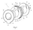
- FIG. 1is an isometric view of a dual coil bobbin assembly, prior to coil winding, of the present invention.
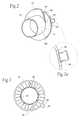
- FIG. 2is an isometric view of a half-bobbin member used in the assembly shown in FIG. 1 .
- FIG. 2 ais an enlarged fragmentary portion of the half-bobbin member.
- FIG. 3is an end view of the flange portion of the half-bottom member of FIG. 2 .
- FIG. 4is a plan view of the inter-fitting components of the dual coil assembly of FIG. 1 .
- FIG. 5is a plan view of the final coil members of the dual coil assembly utilizing the bobbin assembly of FIG. 1 .
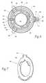
- FIG. 6is an end view of the assembly illustrated in FIG. 5, and showing the labyrinth construction for retaining and routing lead wires of the finished coil assembly of FIG. 5 .
- FIG. 7is an isometric view of a bobbin cover.
- the present inventionhas particular application to a bobbin wound coil for a dual action solenoid, indicated generally by the reference character 11 , as shown in the view of FIG. 5, the finished wound coil assembly includes a push coil 13 and a pull coil 15 , each of which coils may be simultaneously wound on a single winding mandrel (not shown).
- the coil assembly 11includes a winding base of three identical half-bobbin members 13 b , 15 a and 15 b .
- Half-bobbin members 13 a and 13 binclude stepped mating edges 17 .
- Half-bobbin members 15 a and 15 binclude stepped mating edges 19 .
- Half-bobbin member 13 aincludes a slightly different configuration than members 13 b , 15 a and 15 b , as will be later discussed herein.
- each of the half-bobbin members 13 b and 15 a , 15 bhave an integrally molded, substantially identical, radially extending flange portion 21 , whereas the integrally molded flange portion 23 of half-bobbin member 13 a provides an outward facing labyrinth surface for the half-bobbin 13 a , as shown in detail in FIG. 6 .
- the inventionfurther contemplates configuring the mating edges 17 and 19 with a stepped surface on each of the facing half-bobbin members 13 a , 13 b and 15 a , 15 b to form inter-locking junctions 24 and 25 , respectively.
- Each of the coils 13 and 15 with their half-bobbin members 13 a and 13 b , and 15 a and 15 bare positioned on a brass (non-magnetic), tubular spool member 27 having outwardly flared ends 28 and 29 , respectively.
- each of the washers 32are provided with anti-rotational means, such as the aperture 30 (see FIG. 3) and a dimple or protuberance (not shown) located on an adjacent washer 32 , which interfit with one another.
- the flanges 21are each additionally provided with integrally molded tabs 34 , which are provided with a frangible area 35 permitting the unused portion to be snapped off by hand, as needed.
- the end flange 23molded integrally with the half-bobbin 13 a , includes a labyrinth of arcuate channels or grooves 37 , 38 , 39 and 40 for guiding and retaining incoming leads 41 , 42 , and 43 , respectively.
- the incoming leads 41 , 42 , and 43reside in a notch 45 formed in the circumference of the flange 23 .
- Diametrically opposed to the notch 45is an integrally formed rectangular grommet 47 which acts to retain the exiting leads 48 , 49 , 50 , and 51 joined to the magnet coil wires 41 , 42 , 46 , and 43 , respectively.
- Each of the flanges 21are identically molded, the flanges 21 contain a slot 56 , which is molded substantially tangential to the circumference of the tubular spool 27 .
- the slot 56 in the flange 21 of the half-bottom member 15 asupports and routes the inner most magnet coil wire (not shown) for winding the coils 13 and 15 , respectively.
- a notch 58is provided in the flanges 21 for supporting the entry end of a magnet coil lead routed through the groove 56 .
- the wound end leads 41 and 42may be guided through the notches 58 of the flanges 21 and washers 32 to lie longitudinally across the wound coil 13 to enter the labyrinth of flange 23 via the notch 45 .
- a cover 60is provided for added protection of the leads contained in the rectangular grommet 47 of the flange 23 and in the well of the flange 23 .
- the cover 60also has a post 62 (see FIG. 7) that press fits into recess 64 shown in FIG. 6 . This holds the cover 60 in place until an adhesive or sealant selectively placed in arcuate channels 37 can cure.
- An orientation tongue 61has the same dimensions as the interior of the grommet 47 , and is seated therein.
- the adhesive/sealantis applied in the areas where the magnet wires are joined to the stranded lead wires.
- This adhesivewhen cured, provides mechanical resistance to vibration, and improved electrical insulation.
Landscapes
- Engineering & Computer Science (AREA)
- Power Engineering (AREA)
- Electromagnets (AREA)
Abstract
Description
Claims (30)
Priority Applications (2)
| Application Number | Priority Date | Filing Date | Title |
|---|---|---|---|
| US09/991,520US6598824B2 (en) | 2001-11-20 | 2001-11-20 | Electrical and mechanical coil system for dual and single action solenoids |
| CA002411704ACA2411704A1 (en) | 2001-11-20 | 2002-11-13 | Electrical and mechanical coil system for dual and single action solenoids |
Applications Claiming Priority (1)
| Application Number | Priority Date | Filing Date | Title |
|---|---|---|---|
| US09/991,520US6598824B2 (en) | 2001-11-20 | 2001-11-20 | Electrical and mechanical coil system for dual and single action solenoids |
Publications (2)
| Publication Number | Publication Date |
|---|---|
| US20030094535A1 US20030094535A1 (en) | 2003-05-22 |
| US6598824B2true US6598824B2 (en) | 2003-07-29 |
Family
ID=25537294
Family Applications (1)
| Application Number | Title | Priority Date | Filing Date |
|---|---|---|---|
| US09/991,520Expired - LifetimeUS6598824B2 (en) | 2001-11-20 | 2001-11-20 | Electrical and mechanical coil system for dual and single action solenoids |
Country Status (2)
| Country | Link |
|---|---|
| US (1) | US6598824B2 (en) |
| CA (1) | CA2411704A1 (en) |
Cited By (27)
| Publication number | Priority date | Publication date | Assignee | Title |
|---|---|---|---|---|
| US20030141954A1 (en)* | 2002-01-25 | 2003-07-31 | Tibbetts Industries, Inc. | Inductive device |
| US20030192186A1 (en)* | 2001-05-15 | 2003-10-16 | Wahl Clipper Corporation | Vibrator motor |
| US20060009052A1 (en)* | 2004-07-07 | 2006-01-12 | Ralf Hoffmann | Relay, in particular for a plug installation, and method for the production thereof |
| US20070090709A1 (en)* | 2003-10-20 | 2007-04-26 | Sumida Corporation | High-voltage transformer |
| US20090174513A1 (en)* | 2008-01-04 | 2009-07-09 | David William Ford | Coil formers for mri magnets |
| US20090201114A1 (en)* | 2008-02-07 | 2009-08-13 | Tyco Electronics Corporation | Bobbin assembly |
| US20100244824A1 (en)* | 2009-03-25 | 2010-09-30 | Longzhi Jiang | Apparatus for supporting and method for forming a support for a magnetic resonance imaging (mri) magnet |
| US20110025305A1 (en)* | 2009-07-31 | 2011-02-03 | James Douglas Lint | Current sensing devices and methods |
| DE102010020042A1 (en)* | 2009-08-28 | 2011-03-03 | Nexans | Coil e.g. machine coil, for e.g. high-voltage cable, has through hole formed as slot and attached at intermediate wall, where through hole runs from core of coil towards outer edge of intermediate wall and opened outwardly at wall |
| US7981034B2 (en) | 2006-02-28 | 2011-07-19 | Abbott Diabetes Care Inc. | Smart messages and alerts for an infusion delivery and management system |
| US8085151B2 (en) | 2007-06-28 | 2011-12-27 | Abbott Diabetes Care Inc. | Signal converting cradle for medical condition monitoring and management system |
| US20120068477A1 (en)* | 2010-09-21 | 2012-03-22 | Remy International, Inc. | Starter solenoid with rectangular coil winding |
| US20120068476A1 (en)* | 2010-09-21 | 2012-03-22 | Remy International, Inc. | Starter solenoid with spool for retaining coils |
| US8206296B2 (en) | 2006-08-07 | 2012-06-26 | Abbott Diabetes Care Inc. | Method and system for providing integrated analyte monitoring and infusion system therapy management |
| CN103119835A (en)* | 2010-09-21 | 2013-05-22 | 瑞美技术有限责任公司 | Starter motor assembly with soft start solenoid |
| US8512244B2 (en) | 2006-06-30 | 2013-08-20 | Abbott Diabetes Care Inc. | Integrated analyte sensor and infusion device and methods therefor |
| US8641618B2 (en) | 2007-06-27 | 2014-02-04 | Abbott Diabetes Care Inc. | Method and structure for securing a monitoring device element |
| US20140225376A1 (en)* | 2013-02-10 | 2014-08-14 | Omnitek Partners Llc | Dynamo-Type Lanyard Operated Event Detection and Power Generators |
| US8932216B2 (en) | 2006-08-07 | 2015-01-13 | Abbott Diabetes Care Inc. | Method and system for providing data management in integrated analyte monitoring and infusion system |
| US9368266B2 (en) | 2014-07-18 | 2016-06-14 | Trumpet Holdings, Inc. | Electric solenoid structure having elastomeric biasing member |
| US20170222523A1 (en)* | 2014-10-01 | 2017-08-03 | University Of Newcastle Upon Tyne | Method and system for manufacture of a compressed coil |
| US9786429B2 (en) | 2011-05-10 | 2017-10-10 | Delta Electronics, Inc. | Bobbin and magnetic module comprising the same |
| US20170294266A1 (en)* | 2014-09-02 | 2017-10-12 | Koninklijke Philips N.V. | Bobbin assembly and method for producing a bobbin assembly |
| US9861164B2 (en)* | 2016-03-15 | 2018-01-09 | Nike, Inc. | Tensioning system and reel member for an article of footwear |
| US10048293B2 (en) | 2012-05-31 | 2018-08-14 | Pulse Electronics, Inc. | Current sensing devices with integrated bus bars |
| US10660406B2 (en) | 2016-03-15 | 2020-05-26 | Nike, Inc. | Tensioning system and reel member for footwear |
| DE102024103943A1 (en)* | 2024-02-13 | 2025-08-14 | Mahle International Gmbh | Electrical machine, method for producing a flattened section on a coil for an electrical machine and a separately excited electrical synchronous machine |
Families Citing this family (15)
| Publication number | Priority date | Publication date | Assignee | Title |
|---|---|---|---|---|
| US7321664B2 (en)* | 2004-01-13 | 2008-01-22 | Sonionmicrotronic Nederland B.V. | Receiver having an improved bobbin |
| US7236079B2 (en)* | 2005-07-23 | 2007-06-26 | Jiuan Lin | Transformer bobbin for preventing excitation peak voltage insulation damage |
| US7808134B2 (en)* | 2006-06-16 | 2010-10-05 | Continental Automotive Canada, Inc. | Active control mount magnetic optimization for an engine |
| US8421565B2 (en) | 2010-09-21 | 2013-04-16 | Remy Technologies Llc | Starter motor solenoid with variable reluctance plunger |
| CN102315044A (en)* | 2011-06-28 | 2012-01-11 | 上海法雷奥汽车电器系统有限公司 | Coil rack for electromagnetic switch and method for winding coils |
| US20140230238A1 (en)* | 2011-11-04 | 2014-08-21 | Yasuhiro Ueno | Manufacturing method of reactor (as amended) |
| CN206516463U (en)* | 2016-11-18 | 2017-09-22 | 普洛西电源有限公司 | The device provided for the winding for enabling non-integer number on inductor |
| CN111344829B (en)* | 2017-11-21 | 2022-11-22 | 三菱电机株式会社 | Electromagnetic switch device for starter |
| NL2020418B1 (en)* | 2018-02-12 | 2019-08-19 | Magnetic Innovations B V | Coil assembly for magnetic actuator, magnetic actuator and manufacturing method |
| EP3618085B1 (en)* | 2018-08-28 | 2022-05-04 | Mahle International GmbH | Coil carrier for an electromagnetic switch |
| USD948994S1 (en)* | 2019-09-24 | 2022-04-19 | Ralph Mugerdichian | Construction line reel |
| EP3944265B1 (en)* | 2020-07-22 | 2024-04-24 | Zhangzhou Hongfa Electroacoustic Co., Ltd. | Bobbin that facilitates automatic winding, coil assembly and latching relay |
| US20220059274A1 (en)* | 2020-08-21 | 2022-02-24 | Astec International Limited | Adjustable Spacer For Magnetic Transformers And Inductors |
| US20230166941A1 (en)* | 2021-11-29 | 2023-06-01 | Hobart Brothers Llc | Welding wire spool with breakaway tab |
| CN118771045B (en)* | 2024-09-11 | 2024-11-22 | 赣州市好莱克纺织实业有限公司 | Polyester cotton cloth winding device with traction function |
Citations (23)
| Publication number | Priority date | Publication date | Assignee | Title |
|---|---|---|---|---|
| US810490A (en)* | 1906-01-23 | Jacob C Knupp | Sand-reel. | |
| US1944582A (en) | 1930-08-12 | 1934-01-23 | Gen Cable Corp | Mandrel |
| US2212798A (en)* | 1938-03-31 | 1940-08-27 | Sole William Cary | Parting flange or divider for drilling drums |
| US2271326A (en)* | 1940-06-14 | 1942-01-27 | George H Bird | Display reel |
| US2355477A (en) | 1942-10-15 | 1944-08-08 | William F Stahl | Form for windings and the like |
| US2787743A (en) | 1953-03-09 | 1957-04-02 | American Molded Products Co | Shell for deflection yoke |
| US3083930A (en) | 1959-08-13 | 1963-04-02 | Honeywell Regulator Co | Winding form |
| US3185948A (en) | 1962-03-14 | 1965-05-25 | Gen Electric | Electrical regulator |
| US3308412A (en) | 1960-04-19 | 1967-03-07 | Physical Sciences Corp | Temperature compensated magnetic transducer |
| US3457534A (en) | 1967-05-23 | 1969-07-22 | Hermetic Coil Co Inc | Electrical coil |
| US3605055A (en) | 1970-07-02 | 1971-09-14 | Gen Electric | Two-piece winding bobbin for watt-hour meter potential coil |
| US3606195A (en) | 1969-02-07 | 1971-09-20 | Durafoam Inc | Molded plastic spool |
| US3661342A (en) | 1970-08-19 | 1972-05-09 | Jackson Controls Co Inc | Operative winding separator |
| USRE27891E (en) | 1971-07-13 | 1974-01-22 | Davisinductor coil | |
| JPS5536973A (en) | 1978-09-06 | 1980-03-14 | Omron Tateisi Electronics Co | Production of coil device |
| US4274136A (en)* | 1978-09-01 | 1981-06-16 | Sony Corporation | Bobbin structure for high voltage transformers |
| US4363014A (en) | 1981-05-06 | 1982-12-07 | Emerson Electric Co. | Snap-on cover for bobbin-wound coil assembly |
| US4462016A (en)* | 1982-12-03 | 1984-07-24 | At&T Technologies, Inc. | Inductor coils with mechanically coupleable bobbins |
| US4739945A (en)* | 1987-04-15 | 1988-04-26 | Yoshida Kogyo K. K. | Spool for winding thereon flexible elongate materials |
| US5600294A (en) | 1994-12-27 | 1997-02-04 | Dana Corporation | Interlocking bobbin and cap for electromagnetic coil assembly |
| US5774036A (en) | 1995-06-30 | 1998-06-30 | Siemens Electric Limited | Bobbin-mounted solenoid coil and method of making |
| US6031443A (en) | 1996-09-30 | 2000-02-29 | Siemens Aktiengesellschaft | Magnetic coil with stepped winding |
| US6073869A (en) | 1998-06-04 | 2000-06-13 | Fair-Rite Products Corporation | Ferrite bobbin formed from two indentical ferrite components |
- 2001
- 2001-11-20USUS09/991,520patent/US6598824B2/ennot_activeExpired - Lifetime
- 2002
- 2002-11-13CACA002411704Apatent/CA2411704A1/ennot_activeAbandoned
Patent Citations (23)
| Publication number | Priority date | Publication date | Assignee | Title |
|---|---|---|---|---|
| US810490A (en)* | 1906-01-23 | Jacob C Knupp | Sand-reel. | |
| US1944582A (en) | 1930-08-12 | 1934-01-23 | Gen Cable Corp | Mandrel |
| US2212798A (en)* | 1938-03-31 | 1940-08-27 | Sole William Cary | Parting flange or divider for drilling drums |
| US2271326A (en)* | 1940-06-14 | 1942-01-27 | George H Bird | Display reel |
| US2355477A (en) | 1942-10-15 | 1944-08-08 | William F Stahl | Form for windings and the like |
| US2787743A (en) | 1953-03-09 | 1957-04-02 | American Molded Products Co | Shell for deflection yoke |
| US3083930A (en) | 1959-08-13 | 1963-04-02 | Honeywell Regulator Co | Winding form |
| US3308412A (en) | 1960-04-19 | 1967-03-07 | Physical Sciences Corp | Temperature compensated magnetic transducer |
| US3185948A (en) | 1962-03-14 | 1965-05-25 | Gen Electric | Electrical regulator |
| US3457534A (en) | 1967-05-23 | 1969-07-22 | Hermetic Coil Co Inc | Electrical coil |
| US3606195A (en) | 1969-02-07 | 1971-09-20 | Durafoam Inc | Molded plastic spool |
| US3605055A (en) | 1970-07-02 | 1971-09-14 | Gen Electric | Two-piece winding bobbin for watt-hour meter potential coil |
| US3661342A (en) | 1970-08-19 | 1972-05-09 | Jackson Controls Co Inc | Operative winding separator |
| USRE27891E (en) | 1971-07-13 | 1974-01-22 | Davisinductor coil | |
| US4274136A (en)* | 1978-09-01 | 1981-06-16 | Sony Corporation | Bobbin structure for high voltage transformers |
| JPS5536973A (en) | 1978-09-06 | 1980-03-14 | Omron Tateisi Electronics Co | Production of coil device |
| US4363014A (en) | 1981-05-06 | 1982-12-07 | Emerson Electric Co. | Snap-on cover for bobbin-wound coil assembly |
| US4462016A (en)* | 1982-12-03 | 1984-07-24 | At&T Technologies, Inc. | Inductor coils with mechanically coupleable bobbins |
| US4739945A (en)* | 1987-04-15 | 1988-04-26 | Yoshida Kogyo K. K. | Spool for winding thereon flexible elongate materials |
| US5600294A (en) | 1994-12-27 | 1997-02-04 | Dana Corporation | Interlocking bobbin and cap for electromagnetic coil assembly |
| US5774036A (en) | 1995-06-30 | 1998-06-30 | Siemens Electric Limited | Bobbin-mounted solenoid coil and method of making |
| US6031443A (en) | 1996-09-30 | 2000-02-29 | Siemens Aktiengesellschaft | Magnetic coil with stepped winding |
| US6073869A (en) | 1998-06-04 | 2000-06-13 | Fair-Rite Products Corporation | Ferrite bobbin formed from two indentical ferrite components |
Cited By (52)
| Publication number | Priority date | Publication date | Assignee | Title |
|---|---|---|---|---|
| US20030192186A1 (en)* | 2001-05-15 | 2003-10-16 | Wahl Clipper Corporation | Vibrator motor |
| US7239053B2 (en)* | 2001-05-15 | 2007-07-03 | Wahl Clipper Corporation | Vibrator motor |
| US20030141954A1 (en)* | 2002-01-25 | 2003-07-31 | Tibbetts Industries, Inc. | Inductive device |
| US6819213B2 (en)* | 2002-01-25 | 2004-11-16 | Tibbetts Industries, Inc. | Inductive device |
| US20070090709A1 (en)* | 2003-10-20 | 2007-04-26 | Sumida Corporation | High-voltage transformer |
| US20060009052A1 (en)* | 2004-07-07 | 2006-01-12 | Ralf Hoffmann | Relay, in particular for a plug installation, and method for the production thereof |
| US9782076B2 (en) | 2006-02-28 | 2017-10-10 | Abbott Diabetes Care Inc. | Smart messages and alerts for an infusion delivery and management system |
| US7981034B2 (en) | 2006-02-28 | 2011-07-19 | Abbott Diabetes Care Inc. | Smart messages and alerts for an infusion delivery and management system |
| US10448834B2 (en) | 2006-02-28 | 2019-10-22 | Abbott Diabetes Care Inc. | Smart messages and alerts for an infusion delivery and management system |
| US9119582B2 (en) | 2006-06-30 | 2015-09-01 | Abbott Diabetes Care, Inc. | Integrated analyte sensor and infusion device and methods therefor |
| US11918782B2 (en) | 2006-06-30 | 2024-03-05 | Abbott Diabetes Care Inc. | Integrated analyte sensor and infusion device and methods therefor |
| US8512244B2 (en) | 2006-06-30 | 2013-08-20 | Abbott Diabetes Care Inc. | Integrated analyte sensor and infusion device and methods therefor |
| US10220145B2 (en) | 2006-06-30 | 2019-03-05 | Abbott Diabetes Care Inc. | Integrated analyte sensor and infusion device and methods therefor |
| US11445910B2 (en) | 2006-08-07 | 2022-09-20 | Abbott Diabetes Care Inc. | Method and system for providing data management in integrated analyte monitoring and infusion system |
| US10206629B2 (en) | 2006-08-07 | 2019-02-19 | Abbott Diabetes Care Inc. | Method and system for providing integrated analyte monitoring and infusion system therapy management |
| US11806110B2 (en) | 2006-08-07 | 2023-11-07 | Abbott Diabetes Care Inc. | Method and system for providing data management in integrated analyte monitoring and infusion system |
| US9697332B2 (en) | 2006-08-07 | 2017-07-04 | Abbott Diabetes Care Inc. | Method and system for providing data management in integrated analyte monitoring and infusion system |
| US8206296B2 (en) | 2006-08-07 | 2012-06-26 | Abbott Diabetes Care Inc. | Method and system for providing integrated analyte monitoring and infusion system therapy management |
| US11967408B2 (en) | 2006-08-07 | 2024-04-23 | Abbott Diabetes Care Inc. | Method and system for providing integrated analyte monitoring and infusion system therapy management |
| US8932216B2 (en) | 2006-08-07 | 2015-01-13 | Abbott Diabetes Care Inc. | Method and system for providing data management in integrated analyte monitoring and infusion system |
| US8727982B2 (en) | 2006-08-07 | 2014-05-20 | Abbott Diabetes Care Inc. | Method and system for providing integrated analyte monitoring and infusion system therapy management |
| US12245839B2 (en) | 2006-08-07 | 2025-03-11 | Abbott Diabetes Care, Inc. | Method and system for providing data management in integrated analyte monitoring and infusion system |
| US8641618B2 (en) | 2007-06-27 | 2014-02-04 | Abbott Diabetes Care Inc. | Method and structure for securing a monitoring device element |
| US8085151B2 (en) | 2007-06-28 | 2011-12-27 | Abbott Diabetes Care Inc. | Signal converting cradle for medical condition monitoring and management system |
| US8502682B2 (en) | 2007-06-28 | 2013-08-06 | Abbott Diabetes Care Inc. | Signal converting cradle for medical condition monitoring and management system |
| US20090174513A1 (en)* | 2008-01-04 | 2009-07-09 | David William Ford | Coil formers for mri magnets |
| US20090201114A1 (en)* | 2008-02-07 | 2009-08-13 | Tyco Electronics Corporation | Bobbin assembly |
| US7859380B2 (en)* | 2008-02-07 | 2010-12-28 | Tyco Electronics Corporation | Bobbin assembly |
| US20100244824A1 (en)* | 2009-03-25 | 2010-09-30 | Longzhi Jiang | Apparatus for supporting and method for forming a support for a magnetic resonance imaging (mri) magnet |
| US7924010B2 (en)* | 2009-03-25 | 2011-04-12 | General Electric Company | Apparatus for supporting and method for forming a support for a magnetic resonance imaging (MRI) magnet |
| US9823274B2 (en)* | 2009-07-31 | 2017-11-21 | Pulse Electronics, Inc. | Current sensing inductive devices |
| US20110025305A1 (en)* | 2009-07-31 | 2011-02-03 | James Douglas Lint | Current sensing devices and methods |
| DE102010020042A1 (en)* | 2009-08-28 | 2011-03-03 | Nexans | Coil e.g. machine coil, for e.g. high-voltage cable, has through hole formed as slot and attached at intermediate wall, where through hole runs from core of coil towards outer edge of intermediate wall and opened outwardly at wall |
| CN103119835B (en)* | 2010-09-21 | 2017-03-08 | 瑞美技术有限责任公司 | Starter motor assembly with soft start solenoid |
| CN103119835A (en)* | 2010-09-21 | 2013-05-22 | 瑞美技术有限责任公司 | Starter motor assembly with soft start solenoid |
| US20120068476A1 (en)* | 2010-09-21 | 2012-03-22 | Remy International, Inc. | Starter solenoid with spool for retaining coils |
| US8477001B2 (en)* | 2010-09-21 | 2013-07-02 | Remy Technologies Llc | Starter solenoid with rectangular coil winding |
| US8525625B2 (en)* | 2010-09-21 | 2013-09-03 | Remy Technologies Llc | Starter solenoid with spool for retaining coils |
| WO2012040102A1 (en)* | 2010-09-21 | 2012-03-29 | Remy Technologies, Llc | Starter solenoid with spool for retaining coils |
| US20120068477A1 (en)* | 2010-09-21 | 2012-03-22 | Remy International, Inc. | Starter solenoid with rectangular coil winding |
| US9786429B2 (en) | 2011-05-10 | 2017-10-10 | Delta Electronics, Inc. | Bobbin and magnetic module comprising the same |
| US10048293B2 (en) | 2012-05-31 | 2018-08-14 | Pulse Electronics, Inc. | Current sensing devices with integrated bus bars |
| US9112390B2 (en)* | 2013-02-10 | 2015-08-18 | Omnitek Partners Llc | Dynamo-type lanyard operated event detection and power generators |
| US20140225376A1 (en)* | 2013-02-10 | 2014-08-14 | Omnitek Partners Llc | Dynamo-Type Lanyard Operated Event Detection and Power Generators |
| US9368266B2 (en) | 2014-07-18 | 2016-06-14 | Trumpet Holdings, Inc. | Electric solenoid structure having elastomeric biasing member |
| US20170294266A1 (en)* | 2014-09-02 | 2017-10-12 | Koninklijke Philips N.V. | Bobbin assembly and method for producing a bobbin assembly |
| US20170222523A1 (en)* | 2014-10-01 | 2017-08-03 | University Of Newcastle Upon Tyne | Method and system for manufacture of a compressed coil |
| US10855152B2 (en)* | 2014-10-01 | 2020-12-01 | Advanced Electric Machines Group Limited | Method and system for manufacture of a compressed coil |
| US9861164B2 (en)* | 2016-03-15 | 2018-01-09 | Nike, Inc. | Tensioning system and reel member for an article of footwear |
| US10660406B2 (en) | 2016-03-15 | 2020-05-26 | Nike, Inc. | Tensioning system and reel member for footwear |
| DE102024103943A1 (en)* | 2024-02-13 | 2025-08-14 | Mahle International Gmbh | Electrical machine, method for producing a flattened section on a coil for an electrical machine and a separately excited electrical synchronous machine |
| WO2025171917A1 (en) | 2024-02-13 | 2025-08-21 | Mahle International Gmbh | Electric machine, method for producing a flattened portion on a coil for an electric machine, and separately excited electric synchronous machine |
Also Published As
| Publication number | Publication date |
|---|---|
| US20030094535A1 (en) | 2003-05-22 |
| CA2411704A1 (en) | 2003-05-20 |
Similar Documents
| Publication | Publication Date | Title |
|---|---|---|
| US6598824B2 (en) | Electrical and mechanical coil system for dual and single action solenoids | |
| US9343930B2 (en) | Segmented stator assembly | |
| US3956651A (en) | Wire stator structure | |
| EP1748534B1 (en) | Stator for electric motors having a winding interconnection assembly | |
| US6107718A (en) | Stator for an electrical machine | |
| US7385323B2 (en) | Armature of rotary electrical device | |
| US5852395A (en) | Rogovski coil | |
| US6304018B1 (en) | Externally-wound stator with improved magnetic transition | |
| KR101967607B1 (en) | Electronically commutated direct-current motor | |
| EP1739809A1 (en) | A central power distributing member for a brushless motor, a brushless motor provided therewith and a method of assembling it | |
| US7780108B2 (en) | Method for winding an electrical machine, and an auxiliary winding body | |
| WO1998044616A9 (en) | Member to form motor stator | |
| US10818427B2 (en) | Stator assembly including a bobbin having an extension tab and a retention rib | |
| US3958328A (en) | Method of making a transformer coil assembly | |
| US3609427A (en) | Field coil structure for electric motor | |
| JPH11299132A (en) | Motor stator core | |
| US7745969B2 (en) | Electrical machine with an end-side deflection of electrical conductors | |
| US11715985B2 (en) | Stator and motor | |
| US5181004A (en) | Solenoid coil assembly | |
| JP2006511189A (en) | Electric machine | |
| WO2019057597A1 (en) | Electric machine | |
| DE102020208464A1 (en) | CONNECTION DEVICE FOR A PRIMARY PART FOR AN ELECTRICAL MACHINE, METHOD OF MANUFACTURING SUCH CONNECTION DEVICE, AND METHOD OF MANUFACTURING AN ELECTRICAL MACHINE | |
| US20240274386A1 (en) | Coil Assembly for an Electromechanical Relay, Electromechanical Relay with a Coil Assembly and Method for Manufacturing a Coil Assembly | |
| KR950704848A (en) | Magnetic field coil for motor | |
| GB2240664A (en) | Locating bobbin windings on stator |
Legal Events
| Date | Code | Title | Description |
|---|---|---|---|
| AS | Assignment | Owner name:TROMBETTA, LLC, WISCONSIN Free format text:ASSIGNMENT OF ASSIGNORS INTEREST;ASSIGNOR:SCHMIDT, STEPHEN M.;REEL/FRAME:012668/0472 Effective date:20020221 | |
| STCF | Information on status: patent grant | Free format text:PATENTED CASE | |
| FPAY | Fee payment | Year of fee payment:4 | |
| FPAY | Fee payment | Year of fee payment:8 | |
| AS | Assignment | Owner name:TRUMPET HOLDINGS, INC., DELAWARE Free format text:ASSIGNMENT OF ASSIGNORS INTEREST;ASSIGNOR:TROMBETTA, LLC;REEL/FRAME:025921/0430 Effective date:20110225 | |
| FPAY | Fee payment | Year of fee payment:12 | |
| AS | Assignment | Owner name:JPMORGAN CHASE BANK, N.A., AS THE ADMINISTRATIVE AGENT, NEW YORK Free format text:SECURITY INTEREST;ASSIGNOR:TRUMPET HOLDINGS, INC.;REEL/FRAME:059178/0841 Effective date:20220304 | |
| AS | Assignment | Owner name:TRUMPET HOLDINGS, INC., NEW YORK Free format text:RELEASE BY SECURED PARTY;ASSIGNOR:JPMORGAN CHASE BANK, N.A., AS ADMINISTRATIVE AGENT;REEL/FRAME:060109/0542 Effective date:20220601 |