US6598502B1 - Multi-swivel connector for a fluid operated tool - Google Patents
Multi-swivel connector for a fluid operated toolDownload PDFInfo
- Publication number
- US6598502B1 US6598502B1US10/058,671US5867102AUS6598502B1US 6598502 B1US6598502 B1US 6598502B1US 5867102 AUS5867102 AUS 5867102AUS 6598502 B1US6598502 B1US 6598502B1
- Authority
- US
- United States
- Prior art keywords
- swivel
- fluid
- post
- connector according
- swivel connector
- Prior art date
- Legal status (The legal status is an assumption and is not a legal conclusion. Google has not performed a legal analysis and makes no representation as to the accuracy of the status listed.)
- Expired - Fee Related
Links
Images


Classifications
- F—MECHANICAL ENGINEERING; LIGHTING; HEATING; WEAPONS; BLASTING
- F16—ENGINEERING ELEMENTS AND UNITS; GENERAL MEASURES FOR PRODUCING AND MAINTAINING EFFECTIVE FUNCTIONING OF MACHINES OR INSTALLATIONS; THERMAL INSULATION IN GENERAL
- F16L—PIPES; JOINTS OR FITTINGS FOR PIPES; SUPPORTS FOR PIPES, CABLES OR PROTECTIVE TUBING; MEANS FOR THERMAL INSULATION IN GENERAL
- F16L39/00—Joints or fittings for double-walled or multi-channel pipes or pipe assemblies
- F16L39/04—Joints or fittings for double-walled or multi-channel pipes or pipe assemblies allowing adjustment or movement
- B—PERFORMING OPERATIONS; TRANSPORTING
- B25—HAND TOOLS; PORTABLE POWER-DRIVEN TOOLS; MANIPULATORS
- B25B—TOOLS OR BENCH DEVICES NOT OTHERWISE PROVIDED FOR, FOR FASTENING, CONNECTING, DISENGAGING OR HOLDING
- B25B21/00—Portable power-driven screw or nut setting or loosening tools; Attachments for drilling apparatus serving the same purpose
- B25B21/004—Portable power-driven screw or nut setting or loosening tools; Attachments for drilling apparatus serving the same purpose of the ratchet type
- B25B21/005—Portable power-driven screw or nut setting or loosening tools; Attachments for drilling apparatus serving the same purpose of the ratchet type driven by a radially acting hydraulic or pneumatic piston
- Y—GENERAL TAGGING OF NEW TECHNOLOGICAL DEVELOPMENTS; GENERAL TAGGING OF CROSS-SECTIONAL TECHNOLOGIES SPANNING OVER SEVERAL SECTIONS OF THE IPC; TECHNICAL SUBJECTS COVERED BY FORMER USPC CROSS-REFERENCE ART COLLECTIONS [XRACs] AND DIGESTS
- Y10—TECHNICAL SUBJECTS COVERED BY FORMER USPC
- Y10T—TECHNICAL SUBJECTS COVERED BY FORMER US CLASSIFICATION
- Y10T137/00—Fluid handling
- Y10T137/8593—Systems
- Y10T137/86268—With running joint between movable parts of system
Definitions
- the present inventionrelates to a multi-swivel connector for connecting a fluid operated tool to a source of fluid, for example to hoses extending from a fluid source.
- Swivel connectors of the above mentioned general typeare known in the art.
- One of such connectorsis disclosed in U.S. Pat. No. 5,311,796.
- Another such connectoris shown in U.S. Pat. No. 6,089,265.
- One of the problems associated with these swivelsis that their freedom of movement can result in safety problems, such as pinch points, which have the potential for injury and hose kinking.
- the freedom of movementmakes it difficult for the operator to attach hoses to the quick connects or to make repairs to the swivels or connectors.
- a multi-swivel connectorfor connecting a fluid operated tool to fluid source.
- the multi-swivel connectorbroadly comprises a post having an axis, swivel means having an axis extending perpendicular to the axis of the post, means for limiting rotation of the swivel means to an arc or range of motion less than 360 degrees, fitting means attached to the swivel means, which fitting means is tiltable around the axis of the swivel means over a range of at least 90 degrees and is rotatable around the axis of the post.
- FIG. 1is an exploded view of a multi-swivel connector in accordance with the present invention
- FIG. 2is a front view of a post used in the multi-swivel connector
- FIG. 3is a top view of the post of FIG. 2;
- FIG. 4is a sectional view of the post of FIG. 2 taken along lines 4 — 4 ;
- FIG. 5is a sectional view of a swivel member forming part of the multi-swivel connector of FIG. 1;
- FIG. 6is a top view of a first member of a fitting means used in the multi-swivel connector of FIG. 1;
- FIG. 7is a top view of a second member of a fitting means used in the multi-swivel connector of FIG. 1;
- FIG. 8is a perspective view of the multi-swivel connector of FIG. 1 illustrating the means for limiting the range of motion of the swivel member;
- FIG. 9is a side view of a power tool in partial cross section having the multi-swivel connector of the present invention connected thereto;
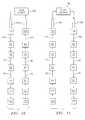
- FIG. 10is a schematic representation of the fluid line connections for operating the drive unit of the power tool in a first operational mode
- FIG. 11is a schematic representation of the fluid line connections for operating the drive unit of the power tool in a second operational mode.
- FIG. 1illustrates the components which make up the multi-swivel connector 10 of the present invention.
- the connector 10includes a post 12 , a swivel member 14 which fits over the post 12 , and a fitting member 16 formed by first and second fitting arms 18 and 20 .
- the swivel member 14may be rotated about a longitudinal axis 22 of the post 12 through a range of motion of less than 360 degrees for safety reasons.
- the swivel member 14has first and second arms 24 and 26 .
- the fitting member 16is attached to the arms 24 and 26 so that the fitting member 16 may tilt relative to the swivel member 14 through a range of motion of at least 90 degrees and preferably through a range of motion of substantially 180 degrees, about an axis 23 which is perpendicular to the axis 22 .
- the post 12has a base member 28 , which is preferably trapezoidal in shape.
- the base member 28is integrally formed with the post 12 ; however, if desired, the base member 28 may be configured to be separable from the post 12 .
- the base member 28 and the post 12are preferably formed from a metallic material, such as aluminum or an aluminum alloy.
- the base member 28has a plurality of openings 30 through which fasteners (not shown) may be inserted to join the post 12 and thus the multi-swivel connector 10 to a power tool 34 .
- the base member 28also has preferably has a hole 36 drilled therein for receiving part of a means 38 for limiting the range of motion of the swivel member 14 .
- the range of motion limiting means 38comprises a first pin 40 which may be machined or assembled.
- the pin 40may be a structure integrally formed with the base member 38 , such as a cast structure.
- the pin 40may be separately manufactured and press fit into and/or adhesively secured to the hole 36 .
- the pin 40is preferably formed from the same material forming the base member 28 ; however, it may be formed from a different material if desired.
- the post 12includes two fluid passageways 42 and 44 .
- the fluid passageway 42has a first fluid port 46 , a first leg 48 communicating with the fluid port 46 , and a second leg 50 substantially perpendicular to the first leg 48 communicating with the first leg 48 and terminating in a second fluid port 52 .
- the fluid passageway 44has a fluid port 54 , a first leg 56 communicating with the fluid port 54 , and a second leg 58 substantially perpendicular to the first leg 56 communicating with the first leg 56 and terminating in a fluid port 60 .
- the first legs 48 and 56 of the fluid passageways 42 and 44respectively have different lengths so that the fluid port 52 is at a different height than the fluid port 60 .
- the post 12also has a series of grooves 62 , 64 , and 66 positioned above and below the fluid ports 52 and 60 .
- Each of the grooves 62 , 64 , and 66receives an O-ring 68 for creating a fluid seal for preventing leakage of fluid.
- Each of the O-rings 68may be formed from any suitable compressible material known in the art.
- the swivel member 14has a central bore 70 which allows the swivel member 14 to be positioned over the post 12 .
- the bore 70has a diameter which is substantially equal to the outer diameter of the post elements which form post grooves 62 , 64 and 66 .
- the bore 70also has smooth walls 76 for allowing the swivel member 14 to rotate about the longitudinal axis of the post 12 while maintaining contact with the seals 68 .
- the swivel member 14also has an integrally formed shoulder element 72 for positioning the swivel member on the post 12 .
- the shoulder element 72has a central opening 74 which allows the top portion of the post 12 to pass therethrough and which allows the shoulder element 72 to rest on post shoulder element 76 .
- a pair of swivel arms 24 and 26extend outwardly from the swivel member 14 along the axis 23 which extends perpendicular to the longitudinal axis of the post 12 .
- Each of the swivel arms 24 and 26has a fluid chamber 78 formed therein.
- Each of the fluid chambers 78is provided with a port 84 which communicates with an annular fluid passageway 86 machined into the respective swivel arm 24 or 26 . Also machined into each of the swivel arms 24 and 26 are grooves 88 and 90 , each of which receives an O-ring 92 for preventing fluid leaks.
- a pin 94is provided on a bottom surface 96 of the swivel member 14 .
- the pin 94forms part of the range limiting means 38 and cooperates with the pin 40 so that the swivel member 14 can only rotate about the longitudinal axis of the post 12 through a range of motion of less than 360 degrees.
- the pin 94may be machined or assembled.
- the pin 94may be a structure integrally formed with the swivel member 14 , such as a cast structure.
- the bottom surface 96may have a hole (not shown) drilled therein and the pin 94 may be press fit into and/or adhesively secured to the hole.
- the pin 94may be formed from the same material as swivel member 14 or a different material.
- one pin 40 on the base member 28may be provided on the base member 28 to allow for a desired limited range of rotational movement for the swivel member 14 , such as a range of rotational movement of less than 350 degrees.
- more than one pin 94may be provided if desired to define a limited range of rotational movement for the swivel member 14 .
- the fitting member 16is formed by first and second fitting arms 18 and 20 .
- Each of the fitting arms 18 and 20has a smooth walled bore 98 which allows a respective one of the arms 18 and 20 to fit over a respective one of the swivel arms 24 and 26 .
- the smooth walled bores 98also allow the fitting arms 18 and 20 and thus the fitting member 16 to tilt relative to the swivel member 14 .
- the fitting member 16may tilt at least 90 degrees about the axis 23 extending perpendicular to the axis 22 of the post 12 and preferably through a range of motion of substantially 180 degrees.
- Each of the fitting arms 18 and 20has an external port 100 and an internal fluid passageway 102 communicating with the external port 100 .
- the passageway 102is in fluid communication with the annular fluid passageway 86 .
- the external port 100is preferably threaded to receive an end of a hose 104 .
- the hose 104may be connected to a fluid source 106 and/or to a return tank (not shown).
- Each of the arms 18 and 20has a portion 108 with an aperture 110 therein.
- the portions 108overlap each other so that the apertures 110 are aligned with each other.
- a fastener(not shown) is inserted into the aligned apertures 110 to lock the fitting arms 18 and 20 together.
- each of the apertures 110may be threaded to receive a threaded fastener.
- the multi-swivel connector 10 of the present inventionmay be used with a fluid operated power tool 34 having a fluid operated piston 114 for operating an action part 116 for acting on an element such as a threaded connector.
- the power tool 34has first and second passageways (not shown) for delivering fluid to and removing fluid from cylinder chambers 118 and 120 on opposite sides of the piston 114 .
- Each of the power tool passagewayshas a respective port 122 and 124 .
- the multi-swivel connector 10may be mounted to the power tool 34 so that the fluid port 46 is aligned with the port 122 and the fluid port 54 is aligned with the port 124 .
- fluid from the fluid source 106 during one portion of the piston strokeis delivered to the chamber 118 via external port 100 and passageway 102 in the fitting arm 20 , annular passageway 86 and fluid chamber 78 in swivel arm 26 , fluid line 82 in the swivel member 14 , first passageway 42 in the post 12 , and port 122 .
- fluidis being removed from the cylinder chamber 118 via port 124 , fluid passageway 44 , fluid line 80 in the swivel member 14 , fluid chamber 78 and annular passageway 86 in swivel arm 24 , and via fluid passageway 102 and external port 100 in fitting arm 18 .
- fluidis delivered to the cylinder chamber 118 via the external port 100 and the fluid passageway 100 in the fitting arm 18 , annular fluid passageway 86 and fluid chamber 78 in the swivel arm 24 , fluid line 80 in the swivel member 14 , fluid passageway 44 and port 124 , while fluid is removed from the cylinder chamber 120 via port 122 , the fluid passageway 42 , the fluid line 82 in the swivel member 14 , fluid chamber 78 and annular passageway 86 in the swivel arm 26 , and passageway 102 and external port 100 in the fitting arm 20 .
- a multi swivel connector 10which can be used with a wide variety of fluid operated power tools.
- the swivel connector 10avoids safety problems, such as those pinch points which have the potential for hose kinking and injury, by limiting the rotational movement of the swivel member 14 to less than 360 degrees, while permitting movement of the fitting member through at least a 90 degree and preferably a 180 degree range of movement.
- operatorscan easily attach hoses to the quick connects and make needed repairs.
- the multi-swivel connectorcan be easily stabilized to facilitate repair and connection attachments/changes.
- fitting meansWhile it is preferred to form the fitting means from two fitting arms that are joined together, the fitting means could be fabricated as a single unitary structure if desired.
- rotation limiting meansWhile it is preferred to form the rotation limiting means from pins, other types of rotation limiting devices, such as tongue and groove arrangements or thread arrangements, may be used if desired.
Landscapes
- Engineering & Computer Science (AREA)
- Mechanical Engineering (AREA)
- General Engineering & Computer Science (AREA)
- Quick-Acting Or Multi-Walled Pipe Joints (AREA)
- Joints Allowing Movement (AREA)
Abstract
Description
Claims (23)
Priority Applications (1)
| Application Number | Priority Date | Filing Date | Title |
|---|---|---|---|
| US10/058,671US6598502B1 (en) | 2002-01-28 | 2002-01-28 | Multi-swivel connector for a fluid operated tool |
Applications Claiming Priority (1)
| Application Number | Priority Date | Filing Date | Title |
|---|---|---|---|
| US10/058,671US6598502B1 (en) | 2002-01-28 | 2002-01-28 | Multi-swivel connector for a fluid operated tool |
Publications (2)
| Publication Number | Publication Date |
|---|---|
| US6598502B1true US6598502B1 (en) | 2003-07-29 |
| US20030140737A1 US20030140737A1 (en) | 2003-07-31 |
Family
ID=27609648
Family Applications (1)
| Application Number | Title | Priority Date | Filing Date |
|---|---|---|---|
| US10/058,671Expired - Fee RelatedUS6598502B1 (en) | 2002-01-28 | 2002-01-28 | Multi-swivel connector for a fluid operated tool |
Country Status (1)
| Country | Link |
|---|---|
| US (1) | US6598502B1 (en) |
Cited By (16)
| Publication number | Priority date | Publication date | Assignee | Title |
|---|---|---|---|---|
| US20100056844A1 (en)* | 2008-09-02 | 2010-03-04 | Battelle Memorial Institute | Brachytherapy seed with fast dissolving matrix for optimal delivery of radionuclides to cancer tissue |
| US7926389B1 (en)* | 2008-10-27 | 2011-04-19 | Davis John D | Hydraulic torque wrench with central strain decoupled global hose connect swivel |
| CN103857952A (en)* | 2011-08-30 | 2014-06-11 | 凯特克分部尤尼克斯公司 | Apparatus for tightening threaded fasteners |
| US20180128391A1 (en)* | 2015-04-07 | 2018-05-10 | Cejn Ab | Nipple |
| US20190129899A1 (en)* | 2005-02-28 | 2019-05-02 | Robert T. And Virginia T. Jenkins As Trustees Of The Jenkins Family Trust Dated Feb. 8, 2002 | Method and/or system for transforming between trees and strings |
| US10733234B2 (en) | 2004-05-28 | 2020-08-04 | Robert T. And Virginia T. Jenkins as Trustees of the Jenkins Family Trust Dated Feb. 8. 2002 | Method and/or system for simplifying tree expressions, such as for pattern matching |
| US11100070B2 (en) | 2005-04-29 | 2021-08-24 | Robert T. and Virginia T. Jenkins | Manipulation and/or analysis of hierarchical data |
| CN113339606A (en)* | 2021-06-30 | 2021-09-03 | 哈尔滨科能熔敷科技股份有限公司 | Rotary connector for medium passage |
| US11204906B2 (en) | 2004-02-09 | 2021-12-21 | Robert T. And Virginia T. Jenkins As Trustees Of The Jenkins Family Trust Dated Feb. 8, 2002 | Manipulating sets of hierarchical data |
| US11281646B2 (en) | 2004-12-30 | 2022-03-22 | Robert T. and Virginia T. Jenkins | Enumeration of rooted partial subtrees |
| US11314766B2 (en) | 2004-10-29 | 2022-04-26 | Robert T. and Virginia T. Jenkins | Method and/or system for manipulating tree expressions |
| US11314709B2 (en) | 2004-10-29 | 2022-04-26 | Robert T. and Virginia T. Jenkins | Method and/or system for tagging trees |
| US20220250228A1 (en)* | 2016-05-02 | 2022-08-11 | Enerpac Tool Group Corp. | Fluid-powered torque wrench with fluid pump controls |
| US11418315B2 (en) | 2004-11-30 | 2022-08-16 | Robert T. and Virginia T. Jenkins | Method and/or system for transmitting and/or receiving data |
| US11615065B2 (en) | 2004-11-30 | 2023-03-28 | Lower48 Ip Llc | Enumeration of trees from finite number of nodes |
| US11663238B2 (en) | 2005-01-31 | 2023-05-30 | Lower48 Ip Llc | Method and/or system for tree transformation |
Families Citing this family (2)
| Publication number | Priority date | Publication date | Assignee | Title |
|---|---|---|---|---|
| EP1960704A1 (en)* | 2005-12-16 | 2008-08-27 | Carl Reiner GmbH | Connection element for connecting to a tubular piece |
| GB0714099D0 (en)* | 2007-07-19 | 2007-08-29 | Torque Tension Systems Ltd | Multi-swivel connector for connecting a fluid source to a fluid operating tool |
Citations (5)
| Publication number | Priority date | Publication date | Assignee | Title |
|---|---|---|---|---|
| US5311796A (en) | 1990-07-23 | 1994-05-17 | Junkers John K | Hydraulic tool |
| US5918424A (en)* | 1997-04-21 | 1999-07-06 | Rice; James | Accommodation units |
| US6039068A (en)* | 1997-08-18 | 2000-03-21 | Centre De Recherche Indust. Du Quebec | Apparatus for shielding an articulated structure |
| US6089265A (en) | 1998-11-06 | 2000-07-18 | Unex Corporation | Multi-swivel connector for connecting a fluid operated tool a source of fluid |
| US6406065B1 (en)* | 1999-07-10 | 2002-06-18 | Gat Gesellschaft Fur Antriebstechnik Mbh | Rotary joint for alternating media |
- 2002
- 2002-01-28USUS10/058,671patent/US6598502B1/ennot_activeExpired - Fee Related
Patent Citations (5)
| Publication number | Priority date | Publication date | Assignee | Title |
|---|---|---|---|---|
| US5311796A (en) | 1990-07-23 | 1994-05-17 | Junkers John K | Hydraulic tool |
| US5918424A (en)* | 1997-04-21 | 1999-07-06 | Rice; James | Accommodation units |
| US6039068A (en)* | 1997-08-18 | 2000-03-21 | Centre De Recherche Indust. Du Quebec | Apparatus for shielding an articulated structure |
| US6089265A (en) | 1998-11-06 | 2000-07-18 | Unex Corporation | Multi-swivel connector for connecting a fluid operated tool a source of fluid |
| US6406065B1 (en)* | 1999-07-10 | 2002-06-18 | Gat Gesellschaft Fur Antriebstechnik Mbh | Rotary joint for alternating media |
Cited By (25)
| Publication number | Priority date | Publication date | Assignee | Title |
|---|---|---|---|---|
| US11204906B2 (en) | 2004-02-09 | 2021-12-21 | Robert T. And Virginia T. Jenkins As Trustees Of The Jenkins Family Trust Dated Feb. 8, 2002 | Manipulating sets of hierarchical data |
| US10733234B2 (en) | 2004-05-28 | 2020-08-04 | Robert T. And Virginia T. Jenkins as Trustees of the Jenkins Family Trust Dated Feb. 8. 2002 | Method and/or system for simplifying tree expressions, such as for pattern matching |
| US11314709B2 (en) | 2004-10-29 | 2022-04-26 | Robert T. and Virginia T. Jenkins | Method and/or system for tagging trees |
| US11314766B2 (en) | 2004-10-29 | 2022-04-26 | Robert T. and Virginia T. Jenkins | Method and/or system for manipulating tree expressions |
| US11615065B2 (en) | 2004-11-30 | 2023-03-28 | Lower48 Ip Llc | Enumeration of trees from finite number of nodes |
| US11418315B2 (en) | 2004-11-30 | 2022-08-16 | Robert T. and Virginia T. Jenkins | Method and/or system for transmitting and/or receiving data |
| US11989168B2 (en) | 2004-12-30 | 2024-05-21 | Lower48 Ip Llc | Enumeration of rooted partial subtrees |
| US11281646B2 (en) | 2004-12-30 | 2022-03-22 | Robert T. and Virginia T. Jenkins | Enumeration of rooted partial subtrees |
| US11663238B2 (en) | 2005-01-31 | 2023-05-30 | Lower48 Ip Llc | Method and/or system for tree transformation |
| US10713274B2 (en)* | 2005-02-28 | 2020-07-14 | Robert T. and Virginia T. Jenkins | Method and/or system for transforming between trees and strings |
| US20190129899A1 (en)* | 2005-02-28 | 2019-05-02 | Robert T. And Virginia T. Jenkins As Trustees Of The Jenkins Family Trust Dated Feb. 8, 2002 | Method and/or system for transforming between trees and strings |
| US12277136B2 (en) | 2005-02-28 | 2025-04-15 | Lower48 Ip Llc | Method and/or system for transforming between trees and strings |
| US11243975B2 (en) | 2005-02-28 | 2022-02-08 | Robert T. and Virginia T. Jenkins | Method and/or system for transforming between trees and strings |
| US11100070B2 (en) | 2005-04-29 | 2021-08-24 | Robert T. and Virginia T. Jenkins | Manipulation and/or analysis of hierarchical data |
| US12013829B2 (en) | 2005-04-29 | 2024-06-18 | Lower48 Ip Llc | Manipulation and/or analysis of hierarchical data |
| US11194777B2 (en) | 2005-04-29 | 2021-12-07 | Robert T. And Virginia T. Jenkins As Trustees Of The Jenkins Family Trust Dated Feb. 8, 2002 | Manipulation and/or analysis of hierarchical data |
| US20100056844A1 (en)* | 2008-09-02 | 2010-03-04 | Battelle Memorial Institute | Brachytherapy seed with fast dissolving matrix for optimal delivery of radionuclides to cancer tissue |
| US7926389B1 (en)* | 2008-10-27 | 2011-04-19 | Davis John D | Hydraulic torque wrench with central strain decoupled global hose connect swivel |
| US11035512B2 (en)* | 2011-08-30 | 2021-06-15 | HYTORC Division Unex Corporation | Apparatus for tightening threaded fasteners |
| US20140230608A1 (en)* | 2011-08-30 | 2014-08-21 | John K. Junkers | Apparatus for tightening threaded fasteners |
| CN103857952A (en)* | 2011-08-30 | 2014-06-11 | 凯特克分部尤尼克斯公司 | Apparatus for tightening threaded fasteners |
| US20180128391A1 (en)* | 2015-04-07 | 2018-05-10 | Cejn Ab | Nipple |
| US20220250228A1 (en)* | 2016-05-02 | 2022-08-11 | Enerpac Tool Group Corp. | Fluid-powered torque wrench with fluid pump controls |
| CN113339606A (en)* | 2021-06-30 | 2021-09-03 | 哈尔滨科能熔敷科技股份有限公司 | Rotary connector for medium passage |
| CN113339606B (en)* | 2021-06-30 | 2022-06-28 | 哈尔滨科能熔敷科技股份有限公司 | Rotary connector for medium passage |
Also Published As
| Publication number | Publication date |
|---|---|
| US20030140737A1 (en) | 2003-07-31 |
Similar Documents
| Publication | Publication Date | Title |
|---|---|---|
| US6598502B1 (en) | Multi-swivel connector for a fluid operated tool | |
| US4219618A (en) | Dental hand tool holder | |
| US6666064B2 (en) | Portable hydraulic crimping tool | |
| US20060283514A1 (en) | Manifold | |
| US20110036606A1 (en) | Motor assembly for pneumatic tool | |
| US4977966A (en) | Seawater hydraulic rotary impact tool | |
| US4384511A (en) | Hydraulic cylinder | |
| EP0999399B1 (en) | Multi-swivel connector for connecting a fluid operated tool to a source of fluid | |
| US20100158601A1 (en) | Swing Pin Assembly And Associated Method | |
| EP0468614B1 (en) | Pivotable connection for fluid operated tool | |
| US5445505A (en) | Manual/pneumatic dual-control oil pump | |
| US20040032123A1 (en) | Angle-adjustable connector | |
| US6772521B2 (en) | Hydraulic punch driver | |
| US20020012566A1 (en) | Releasable lockable joint apparatus | |
| US5058859A (en) | Screw-joint type pneumatic tool connector | |
| HK1024050B (en) | Multi-swivel connector for connecting a fluid operated tool to a source of fluid | |
| CN211436669U (en) | Piston device of power sprayer | |
| US5407106A (en) | Automatic/manual sealant disperser with attachable handle and reversible valve seat | |
| JP2000356083A (en) | Down hammer | |
| JPS6272904A (en) | Apparatus for controlling rotary flow amount | |
| JPS6249092A (en) | Two-port swivel joint | |
| JP2539146Y2 (en) | Swash plate type compound hydraulic pump | |
| WO1985002638A1 (en) | Mechanism for connecting attachment | |
| JPH0514748U (en) | Direction switching valve | |
| US6302012B1 (en) | Arrangement for the supply of pressure medium to a hydraulic or pneumatic cylinder |
Legal Events
| Date | Code | Title | Description |
|---|---|---|---|
| AS | Assignment | Owner name:TITAN TECHNOLOGIES INTERNATIONAL, INC., CONNECTICU Free format text:ASSIGNMENT OF ASSIGNORS INTEREST;ASSIGNOR:ROSA, PETER A.;REEL/FRAME:012540/0734 Effective date:20020125 | |
| AS | Assignment | Owner name:SUN NATIONAL BANK, NEW JERSEY Free format text:PATENT COLLATERAL ASSIGNMENT;ASSIGNOR:TITAN TECHNOLOGIES INTERNATIONAL, INC.;REEL/FRAME:018584/0074 Effective date:20061117 Owner name:SUN NATIONAL BANK, NEW JERSEY Free format text:PATENT COLLATERAL ASSIGNMENT;ASSIGNORS:TITAN TECHNOLOGIES INTERNATIONAL, INC.;TTI HOLDINGS, L.L.C.;REEL/FRAME:018584/0131 Effective date:20061117 | |
| REMI | Maintenance fee reminder mailed | ||
| LAPS | Lapse for failure to pay maintenance fees | ||
| STCH | Information on status: patent discontinuation | Free format text:PATENT EXPIRED DUE TO NONPAYMENT OF MAINTENANCE FEES UNDER 37 CFR 1.362 | |
| FP | Lapsed due to failure to pay maintenance fee | Effective date:20070729 | |
| FEPP | Fee payment procedure | Free format text:PETITION RELATED TO MAINTENANCE FEES FILED (ORIGINAL EVENT CODE: PMFP); ENTITY STATUS OF PATENT OWNER: LARGE ENTITY | |
| FEPP | Fee payment procedure | Free format text:PETITION RELATED TO MAINTENANCE FEES DISMISSED (ORIGINAL EVENT CODE: PMFS); ENTITY STATUS OF PATENT OWNER: LARGE ENTITY | |
| REFU | Refund | Free format text:REFUND - PAYMENT OF MAINTENANCE FEE, 4TH YEAR, LARGE ENTITY (ORIGINAL EVENT CODE: R1551); ENTITY STATUS OF PATENT OWNER: LARGE ENTITY Free format text:REFUND - SURCHARGE, PETITION TO ACCEPT PYMT AFTER EXP, UNAVOIDABLE (ORIGINAL EVENT CODE: R1557); ENTITY STATUS OF PATENT OWNER: LARGE ENTITY | |
| FEPP | Fee payment procedure | Free format text:PAYOR NUMBER ASSIGNED (ORIGINAL EVENT CODE: ASPN); ENTITY STATUS OF PATENT OWNER: LARGE ENTITY | |
| AS | Assignment | Owner name:CHICAGO PNEUMATIC TOOL COMPANY LLC, SOUTH CAROLINA Free format text:ASSIGNMENT OF ASSIGNORS INTEREST;ASSIGNOR:TITAN TECHNOLOGIES INTERNATIONAL, INC.;REEL/FRAME:034636/0480 Effective date:20141231 |