US6598306B2 - Self-loading spatial reference point array - Google Patents
Self-loading spatial reference point arrayDownload PDFInfo
- Publication number
- US6598306B2 US6598306B2US09/836,954US83695401AUS6598306B2US 6598306 B2US6598306 B2US 6598306B2US 83695401 AUS83695401 AUS 83695401AUS 6598306 B2US6598306 B2US 6598306B2
- Authority
- US
- United States
- Prior art keywords
- points
- assemblage
- array
- reference points
- sub
- Prior art date
- Legal status (The legal status is an assumption and is not a legal conclusion. Google has not performed a legal analysis and makes no representation as to the accuracy of the status listed.)
- Expired - Lifetime
Links
Images


Classifications
- G—PHYSICS
- G01—MEASURING; TESTING
- G01B—MEASURING LENGTH, THICKNESS OR SIMILAR LINEAR DIMENSIONS; MEASURING ANGLES; MEASURING AREAS; MEASURING IRREGULARITIES OF SURFACES OR CONTOURS
- G01B21/00—Measuring arrangements or details thereof, where the measuring technique is not covered by the other groups of this subclass, unspecified or not relevant
- G01B21/02—Measuring arrangements or details thereof, where the measuring technique is not covered by the other groups of this subclass, unspecified or not relevant for measuring length, width, or thickness
- G01B21/04—Measuring arrangements or details thereof, where the measuring technique is not covered by the other groups of this subclass, unspecified or not relevant for measuring length, width, or thickness by measuring coordinates of points
- G01B21/042—Calibration or calibration artifacts
Definitions
- This inventionrelates to spatial measurement devices and to coordinate grid patterns used as reference in connection with certain types of spatial measurement, and more particularly to reference point arrays used in connection with swiveling, coordinate measuring arms of the type disclosed in my U.S. Pat. No. 5,829,148 issued Nov. 3, 1998, which patent is incorporated by reference in this specification.
- a swiveling, spatial coordinate measuring armhas a limited reach in any direction of typically 1,500 mm, When taking measurements upon a large work piece such as an automobile, the arm must be moved to an number of locations. These locations must be precisely identified in reference to a large, volumetric coordinate system having a singular origin, also known as a global coordinate system.
- One of the most common and most practical methods of achieving global measurements with an articulated arm of limited reachis to define the location of the arm in relation to three known points in a surrounding reference grid or matrix. Each reference point on the grid or matrix carries a unique identification.
- the tip of the arm probeis successively positioned upon three identified points on the grid or matrix, each time the operator manually enters into the associated data processing system the unique identification of each reference point, the data processing system uses the three measurements to calculate the exact position in the arm. The coordinates of that position are then taken into account when determining the result of future measurements in reference to the global coordinate system.
- the manual entry by an operator of the three reference point identificationsis not only time consuming, but is subject to human errors. Indeed, in a work environment, the labeling of a reference point identification may be difficult to read due to poor lighting conditions or obstruction by dust or debris. A single digit error in manipulating an entry keypad or keyboard can yield erroneous measurements.
- This inventionresults from an attempt to eliminate the above-described weakness in the use of a swiveling spatial coordinate measuring arm or other similar spatial measuring devices on large work pieces.
- the principal and secondary objects of the instant inventionare to optimize the use of a swiveling, spatial coordinate measuring arm or similar spatial measurement device having a limited reach when making measurements over a large work piece that requires relocation of the measuring instrument, by providing a reference grid or matrix pattern whereby the displacement or relocation of the measuring instrument is automatically loaded into the associated data processing system through a simple maneuver which does not require any kind of human operation subject to human error; and to provide a new type of spatial reference pattern for use in these and other types of spatial measurements.
- FIG. 1is a perspective view of a work site equipped with a self-loading reference pattern according to the invention
- FIG. 2is a cross-sectional view of the reference point layout
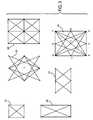
- FIG. 3is a map of possible triangular configurations
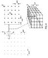
- FIG. 4is a map of grid pattern variations
- FIGS. 5-9are flow diagrams of a computer program used in the creation of the reference pattern.
- FIG. 10is a flow diagram of a computer program using the self-loading pattern.
- FIG. 1an examplary work shop environment in which a swiveling, spatial coordinate measuring arm 1 and its associated data processor 2 are used to conduct measurements on a three-dimensional work piece 3 , in this case, an automobile body.
- a coordinate pattern of reference points or benchmarks 4is permanently applied to the floor 5 , ceiling 6 and surrounding walls 7 - 9 of the work room.
- the reference pointsare distributed and spaced apart in such a way that three of those points are always within the reach of the measuring arm 1 no matter at what location or situs the arm is positioned.
- the reference pointsare arranged in a pattern of rows and columns that do not follow exactly linear and symmetric coordinate lines such as the one shown in dotted line in the drawing. Instead, the reference points are laid out in a distorted pattern that yields some important advantages as will be explained below.
- each benchmark 4consists of a small slab 11 permanently embedded into the surface layer 12 of a floor, wall or ceiling.
- a conical cavity 13is dimensioned to intimately nest or accommodate a ball 14 mounted on the tip 15 of the arm measuring probe.
- the cavityis shaped and dimensioned so that when the ball 14 is inserted, the center 16 of the ball lies at the reference point on the axis 19 of the cavity.
- An obviously equivalent version of the reference pointwould use a spherical or hemispherical benchmark to be contacted by a concavely conical probe tip.
- the reference pointsare distributed such that a triangle 17 defined by a first set of three of said points 4 A, 4 B and 4 C which are located within a defined proximity from one another, differs from any other triangle 18 defined by any second set of three of said points providing that said first and second sets have not no more than two reference points in common. Consequently, the distances and orientations from any location or situs within the work space where the measuring instrument is located to the first set of three points defining the first triangle 17 differ from the distances and orientations from said situs to any other set of points defining a second triangle 18 anywhere else in the whole coordinate pattern. Accordingly, the location coordinates of that situs can be accurately derived from measurements of the positions of any three reference points located within a defined proximity to one another.
- This defined proximitymay consist of reference points defining a two-by-two sub-array, and preferably, may consist of reference points defining a three-by-three sub-array.
- the required proximity of the triangle-forming reference pointmay consist of three-dimensional two-by-two-by-two or three-by-three-by-three sub-arrays.
- FIG. 3illustrates, in top plan views, all the possible triangular configurations that can be formed by joining three reference points within those sub-arrays.
- Four triangular configurations 21can be found in a two-by-two sub-array.
- the number of triangular configurationsis not only doubled, but six additional configurations 22 and 23 are possible; for a total of fourteen configurations.
- a three-by-three sub-arraythere first is the same number of triangular configurations found in a two-by-two array times four 24 ; that is sixteen configurations. Moreover, there is also the same six additional configurations found in a two-by-three array times four; that is forty-six more configurations
- the number of triangular configurationsis 2,268 assuming that the sharp-angle configurations 26 are avoided.
- the number of configurations that must be uniquely implementedcan be dramatically reduced in that case by requiring that four closely spaced apart reference points be measured, that is, that four points defining a pyramid rather than a triangle be used. It should be understood that, in the case of a three dimensional sub-array, any two points of a triangle can be at the same or different level. In practice, it has been found convenient to avoid selecting three reference points that create a triangle having a very sharp angle. The use of such a sharp triangle may affect the precision of the measurement.
- the distortion of the grid patternis preferably accomplished in a two dimensional manner, that is in the single plane, the deviation of any reference point from the location where it should be, if positioned in a regular coordinate grid, can be implemented in any direction that in three dimensions, if necessary.
- a distorted coordinate reference point arrayis accomplished by successively calculating the distortion to be applied to the fourth and subsequent reference points through a trial and error method. An arbitrary amount of distortion is selected then all the triangles that can be formed from that reference point are checked for symmetry with any other triangle which could possibly be formed by joining any three points in the array that have been already offset. This determination process can be conveniently accomplished with the use of relatively simply computer programs as illustrated by the following example.
- a regular coordinate grid pattern 27having a total reference point Grid Count (GC) of forty-two arranged into a Grid Row Count (GRC) of seven and a Grid Column Count (GCC) of six as shown in FIG. 4 .
- GCGrid Count
- GCCGrid Column Count
- each point 28will be allowed to deviate from its normal position within a surrounding planar variation array 29 having a Variation Row Count (VRC) of five, and a Variation Column Count (VCC) of also five.
- VRCVariation Row Count
- VCCVariation Column Count
- the normal reference gridhas a column spacing or Grid column Pitch (GCP) which is equal to the spacing between rows or its Grid Row Pitch (GRP).
- the distorted position of all reference pointscan be obtained by use of a computer program based upon the flow diagrams illustrated in FIGS. 5-8, given GCP, GRP, GCC, and GRC, wherein TOL represents the tolerance available for installing each reference point slab, RN signifies a random number, and TC 1 , TC 2 , TC 3 . . . corresponds to trial counts 1 , 2 , 3 etc. . . . .
- VLPVariation Level Pitch
- FIGS. 6-9illustrate the construction, validation and storage of each point in all possible triangles after the offsetting of a reference point in the grid, using a planar variation sub-array.
Landscapes
- Physics & Mathematics (AREA)
- General Physics & Mathematics (AREA)
- Length Measuring Devices With Unspecified Measuring Means (AREA)
- A Measuring Device Byusing Mechanical Method (AREA)
- Semiconductor Memories (AREA)
- Magnetic Heads (AREA)
- Automatic Control Of Machine Tools (AREA)
- Body Structure For Vehicles (AREA)
- Control Of Position Or Direction (AREA)
Abstract
Description
Claims (26)
Priority Applications (8)
| Application Number | Priority Date | Filing Date | Title |
|---|---|---|---|
| US09/836,954US6598306B2 (en) | 2001-04-17 | 2001-04-17 | Self-loading spatial reference point array |
| JP2002581917AJP3943030B2 (en) | 2001-04-17 | 2002-04-17 | Self-loading spatial reference point array |
| AT02762147TATE475864T1 (en) | 2001-04-17 | 2002-04-17 | DEVICE AND METHOD FOR AUTOMATICALLY DETERMINING THE POSITION OF A MEASURING ARM USING AN ARRANGEMENT OF REFERENCE POINTS |
| DE60237150TDE60237150D1 (en) | 2001-04-17 | 2002-04-17 | DEVICE AND METHOD FOR AUTOMATICALLY DETERMINING THE POSITION OF A MEASURING ARM AFTER ARRANGEMENT OF REFERENCE POINTS |
| HK05104499.3AHK1072463B (en) | 2001-04-17 | 2002-04-17 | Self-loading spatial reference point array |
| EP02762147AEP1390688B1 (en) | 2001-04-17 | 2002-04-17 | Apparatus and method for automatically determining the position of a measuring arm on the basis of an array of reference points |
| CNB028084047ACN1314939C (en) | 2001-04-17 | 2002-04-17 | Self-loading spatial reference point array |
| PCT/US2002/012318WO2002084209A1 (en) | 2001-04-17 | 2002-04-17 | Self-loading spatial reference point array |
Applications Claiming Priority (1)
| Application Number | Priority Date | Filing Date | Title |
|---|---|---|---|
| US09/836,954US6598306B2 (en) | 2001-04-17 | 2001-04-17 | Self-loading spatial reference point array |
Publications (2)
| Publication Number | Publication Date |
|---|---|
| US20030066202A1 US20030066202A1 (en) | 2003-04-10 |
| US6598306B2true US6598306B2 (en) | 2003-07-29 |
Family
ID=25273127
Family Applications (1)
| Application Number | Title | Priority Date | Filing Date |
|---|---|---|---|
| US09/836,954Expired - LifetimeUS6598306B2 (en) | 2001-04-17 | 2001-04-17 | Self-loading spatial reference point array |
Country Status (7)
| Country | Link |
|---|---|
| US (1) | US6598306B2 (en) |
| EP (1) | EP1390688B1 (en) |
| JP (1) | JP3943030B2 (en) |
| CN (1) | CN1314939C (en) |
| AT (1) | ATE475864T1 (en) |
| DE (1) | DE60237150D1 (en) |
| WO (1) | WO2002084209A1 (en) |
Cited By (60)
| Publication number | Priority date | Publication date | Assignee | Title |
|---|---|---|---|---|
| US20040210553A1 (en)* | 2003-04-15 | 2004-10-21 | Eaton Homer L. | Spatial coordinate-based method for identifying work pieces |
| US6901673B1 (en)* | 2004-05-20 | 2005-06-07 | The Boeing Company | Tie-in device for the correlation of coordinate systems |
| US20050151963A1 (en)* | 2004-01-14 | 2005-07-14 | Sandeep Pulla | Transprojection of geometry data |
| US20060107542A1 (en)* | 2004-10-30 | 2006-05-25 | Gee-Wook Song | Three axial displacement measuring apparatus |
| US20070097382A1 (en)* | 2005-10-21 | 2007-05-03 | Romer | System for identifying the position of three-dimensional machine for measuring or machining in a fixed frame of reference |
| US20070256311A1 (en)* | 2006-05-01 | 2007-11-08 | Paul Ferrari | Sealed battery for coordinate measurement machine |
| US20080127501A1 (en)* | 2006-11-20 | 2008-06-05 | Eaton Homer L | Coordinate measurement machine with improved joint |
| US20090010740A1 (en)* | 2008-03-28 | 2009-01-08 | Paul Ferrari | Coordinate measuring machine with rotatable grip |
| US20090013548A1 (en)* | 2006-12-22 | 2009-01-15 | Paul Ferrari | Joint axis for coordinate measurement machine |
| US20090013547A1 (en)* | 2007-07-09 | 2009-01-15 | Paul Ferrari | Joint for coordinate measurement device |
| US20090083985A1 (en)* | 2007-09-28 | 2009-04-02 | Romer / Cimcore | Coordinate measurement machine |
| US7578069B2 (en) | 2004-01-14 | 2009-08-25 | Hexagon Metrology, Inc. | Automated robotic measuring system |
| USD599226S1 (en) | 2008-04-11 | 2009-09-01 | Hexagon Metrology, Inc. | Portable coordinate measurement machine |
| US20090243532A1 (en)* | 2005-09-13 | 2009-10-01 | Romer Inc. | Vehicle having an articulator |
| US20090241360A1 (en)* | 2008-03-28 | 2009-10-01 | Hogar Tait | Systems and methods for improved coordination acquisition member comprising calibration information |
| US20090271996A1 (en)* | 2008-05-05 | 2009-11-05 | Paul Ferrari | Systems and methods for calibrating a portable coordinate measurement machine |
| US20100095542A1 (en)* | 2008-10-16 | 2010-04-22 | Romer, Inc. | Articulating measuring arm with laser scanner |
| US7805854B2 (en) | 2006-05-15 | 2010-10-05 | Hexagon Metrology, Inc. | Systems and methods for positioning and measuring objects using a CMM |
| US20100325907A1 (en)* | 2009-06-30 | 2010-12-30 | Hexagon Metrology Ab | Coordinate measurement machine with vibration detection |
| US20110107612A1 (en)* | 2009-11-06 | 2011-05-12 | Hexagon Metrology Ab | Articulated arm |
| US20110178758A1 (en)* | 2010-01-20 | 2011-07-21 | Faro Technologies, Inc. | Integrated part temperature measurement system |
| US20110176148A1 (en)* | 2010-01-20 | 2011-07-21 | Faro Technologies, Inc. | Coordinate measuring machine having an illuminated probe end and method of operation |
| USD643319S1 (en) | 2010-03-29 | 2011-08-16 | Hexagon Metrology Ab | Portable coordinate measurement machine |
| US20110213247A1 (en)* | 2010-01-08 | 2011-09-01 | Hexagon Metrology, Inc. | Articulated arm with imaging device |
| US8127458B1 (en) | 2010-08-31 | 2012-03-06 | Hexagon Metrology, Inc. | Mounting apparatus for articulated arm laser scanner |
| US8533967B2 (en) | 2010-01-20 | 2013-09-17 | Faro Technologies, Inc. | Coordinate measurement machines with removable accessories |
| US8615893B2 (en) | 2010-01-20 | 2013-12-31 | Faro Technologies, Inc. | Portable articulated arm coordinate measuring machine having integrated software controls |
| US8630314B2 (en) | 2010-01-11 | 2014-01-14 | Faro Technologies, Inc. | Method and apparatus for synchronizing measurements taken by multiple metrology devices |
| US8638446B2 (en) | 2010-01-20 | 2014-01-28 | Faro Technologies, Inc. | Laser scanner or laser tracker having a projector |
| US8677643B2 (en) | 2010-01-20 | 2014-03-25 | Faro Technologies, Inc. | Coordinate measurement machines with removable accessories |
| US8763267B2 (en) | 2012-01-20 | 2014-07-01 | Hexagon Technology Center Gmbh | Locking counterbalance for a CMM |
| US8832954B2 (en) | 2010-01-20 | 2014-09-16 | Faro Technologies, Inc. | Coordinate measurement machines with removable accessories |
| US8875409B2 (en) | 2010-01-20 | 2014-11-04 | Faro Technologies, Inc. | Coordinate measurement machines with removable accessories |
| US8898919B2 (en) | 2010-01-20 | 2014-12-02 | Faro Technologies, Inc. | Coordinate measurement machine with distance meter used to establish frame of reference |
| US8931184B1 (en)* | 2012-05-21 | 2015-01-13 | General Electric Company | Method for dimensionally inspecting a component of a gas turbine system |
| US8997362B2 (en) | 2012-07-17 | 2015-04-07 | Faro Technologies, Inc. | Portable articulated arm coordinate measuring machine with optical communications bus |
| US9069355B2 (en) | 2012-06-08 | 2015-06-30 | Hexagon Technology Center Gmbh | System and method for a wireless feature pack |
| US9074883B2 (en) | 2009-03-25 | 2015-07-07 | Faro Technologies, Inc. | Device for optically scanning and measuring an environment |
| US9113023B2 (en) | 2009-11-20 | 2015-08-18 | Faro Technologies, Inc. | Three-dimensional scanner with spectroscopic energy detector |
| US9163921B2 (en) | 2013-12-18 | 2015-10-20 | Hexagon Metrology, Inc. | Ultra-portable articulated arm coordinate measurement machine |
| US9163922B2 (en) | 2010-01-20 | 2015-10-20 | Faro Technologies, Inc. | Coordinate measurement machine with distance meter and camera to determine dimensions within camera images |
| US9168654B2 (en) | 2010-11-16 | 2015-10-27 | Faro Technologies, Inc. | Coordinate measuring machines with dual layer arm |
| US9210288B2 (en) | 2009-11-20 | 2015-12-08 | Faro Technologies, Inc. | Three-dimensional scanner with dichroic beam splitters to capture a variety of signals |
| US9250214B2 (en) | 2013-03-12 | 2016-02-02 | Hexagon Metrology, Inc. | CMM with flaw detection system |
| US9329271B2 (en) | 2010-05-10 | 2016-05-03 | Faro Technologies, Inc. | Method for optically scanning and measuring an environment |
| US9372265B2 (en) | 2012-10-05 | 2016-06-21 | Faro Technologies, Inc. | Intermediate two-dimensional scanning with a three-dimensional scanner to speed registration |
| US9417056B2 (en) | 2012-01-25 | 2016-08-16 | Faro Technologies, Inc. | Device for optically scanning and measuring an environment |
| US9417316B2 (en) | 2009-11-20 | 2016-08-16 | Faro Technologies, Inc. | Device for optically scanning and measuring an environment |
| US9513107B2 (en) | 2012-10-05 | 2016-12-06 | Faro Technologies, Inc. | Registration calculation between three-dimensional (3D) scans based on two-dimensional (2D) scan data from a 3D scanner |
| US9529083B2 (en) | 2009-11-20 | 2016-12-27 | Faro Technologies, Inc. | Three-dimensional scanner with enhanced spectroscopic energy detector |
| US9551575B2 (en) | 2009-03-25 | 2017-01-24 | Faro Technologies, Inc. | Laser scanner having a multi-color light source and real-time color receiver |
| US9594250B2 (en) | 2013-12-18 | 2017-03-14 | Hexagon Metrology, Inc. | Ultra-portable coordinate measurement machine |
| US9607239B2 (en) | 2010-01-20 | 2017-03-28 | Faro Technologies, Inc. | Articulated arm coordinate measurement machine having a 2D camera and method of obtaining 3D representations |
| US9628775B2 (en) | 2010-01-20 | 2017-04-18 | Faro Technologies, Inc. | Articulated arm coordinate measurement machine having a 2D camera and method of obtaining 3D representations |
| US9759540B2 (en) | 2014-06-11 | 2017-09-12 | Hexagon Metrology, Inc. | Articulating CMM probe |
| US10067231B2 (en) | 2012-10-05 | 2018-09-04 | Faro Technologies, Inc. | Registration calculation of three-dimensional scanner data performed between scans based on measurements by two-dimensional scanner |
| US10175037B2 (en) | 2015-12-27 | 2019-01-08 | Faro Technologies, Inc. | 3-D measuring device with battery pack |
| US10281259B2 (en) | 2010-01-20 | 2019-05-07 | Faro Technologies, Inc. | Articulated arm coordinate measurement machine that uses a 2D camera to determine 3D coordinates of smoothly continuous edge features |
| USD875573S1 (en) | 2018-09-26 | 2020-02-18 | Hexagon Metrology, Inc. | Scanning device |
| US11022434B2 (en) | 2017-11-13 | 2021-06-01 | Hexagon Metrology, Inc. | Thermal management of an optical scanning device |
Families Citing this family (21)
| Publication number | Priority date | Publication date | Assignee | Title |
|---|---|---|---|---|
| DE102004010033A1 (en)* | 2004-03-02 | 2005-09-22 | Dr.Ing.H.C. F. Porsche Ag | measuring device |
| JP4323412B2 (en)* | 2004-11-02 | 2009-09-02 | 株式会社ミツトヨ | Surface texture measuring probe and microscope using the same |
| KR100809533B1 (en)* | 2006-09-21 | 2008-03-04 | 삼성중공업 주식회사 | Global coordinate generation method for precise measurement of space |
| EP2108917B1 (en)* | 2008-04-07 | 2012-10-03 | Leica Geosystems AG | Articulated arm coordinate measuring machine |
| US9482755B2 (en) | 2008-11-17 | 2016-11-01 | Faro Technologies, Inc. | Measurement system having air temperature compensation between a target and a laser tracker |
| US8619265B2 (en) | 2011-03-14 | 2013-12-31 | Faro Technologies, Inc. | Automatic measurement of dimensional data with a laser tracker |
| US9377885B2 (en) | 2010-04-21 | 2016-06-28 | Faro Technologies, Inc. | Method and apparatus for locking onto a retroreflector with a laser tracker |
| US9400170B2 (en) | 2010-04-21 | 2016-07-26 | Faro Technologies, Inc. | Automatic measurement of dimensional data within an acceptance region by a laser tracker |
| US9772394B2 (en) | 2010-04-21 | 2017-09-26 | Faro Technologies, Inc. | Method and apparatus for following an operator and locking onto a retroreflector with a laser tracker |
| CN102155911B (en)* | 2010-12-30 | 2013-06-05 | 二重集团(德阳)重型装备股份有限公司 | Method and application for repeatedly locating workpiece with laser tracking technology |
| GB2503390B (en) | 2011-03-03 | 2014-10-29 | Faro Tech Inc | Target apparatus and method |
| US9164173B2 (en) | 2011-04-15 | 2015-10-20 | Faro Technologies, Inc. | Laser tracker that uses a fiber-optic coupler and an achromatic launch to align and collimate two wavelengths of light |
| US9482529B2 (en) | 2011-04-15 | 2016-11-01 | Faro Technologies, Inc. | Three-dimensional coordinate scanner and method of operation |
| JP2014516409A (en) | 2011-04-15 | 2014-07-10 | ファロ テクノロジーズ インコーポレーテッド | Improved position detector for laser trackers. |
| CN102393169B (en)* | 2011-09-06 | 2013-12-18 | 江苏阳明船舶装备制造技术有限公司 | Three-guy-rope measuring method for measuring gathering pipe |
| WO2013112455A1 (en)* | 2012-01-27 | 2013-08-01 | Faro Technologies, Inc. | Inspection method with barcode identification |
| US9041914B2 (en) | 2013-03-15 | 2015-05-26 | Faro Technologies, Inc. | Three-dimensional coordinate scanner and method of operation |
| DE102014209040B4 (en) | 2014-05-13 | 2019-02-14 | Carl Mahr Holding Gmbh | Method for calibrating a measuring device |
| US9395174B2 (en) | 2014-06-27 | 2016-07-19 | Faro Technologies, Inc. | Determining retroreflector orientation by optimizing spatial fit |
| CN104354073A (en)* | 2014-12-01 | 2015-02-18 | 鲁玉琼 | Coaxiality deviation measurement digital display device and coaxiality deviation calculation method |
| CN109443273B (en)* | 2018-09-28 | 2020-08-07 | 易思维(杭州)科技有限公司 | Method for accurately positioning workpiece to be measured by using three-dimensional measurement system |
Citations (16)
| Publication number | Priority date | Publication date | Assignee | Title |
|---|---|---|---|---|
| US3209462A (en)* | 1963-06-24 | 1965-10-05 | Norman M Harford | Apparatus for and method of sighting and adjusting floodlamps |
| US3425134A (en)* | 1967-04-17 | 1969-02-04 | Louis R Christensen | Set-up gage for punch press,etc. |
| US3463479A (en)* | 1966-12-09 | 1969-08-26 | Zip Products Inc | Workpiece positioning device for machine tool vises |
| US3537697A (en)* | 1967-04-14 | 1970-11-03 | Molins Organisation Ltd | Devices for securing or positioning workpieces for machining operations |
| US3723928A (en)* | 1969-05-05 | 1973-03-27 | Gen Dynamics Corp | Magnetically held measuring and locating fixtures |
| US3982837A (en)* | 1975-01-24 | 1976-09-28 | Controlled Environment Systems, Inc. | Method and apparatus for calibrating Reseau grids |
| US4442607A (en)* | 1981-11-25 | 1984-04-17 | Mitutoyo Mfg. Co., Ltd. | Measuring instrument |
| US4549359A (en)* | 1983-11-17 | 1985-10-29 | Applied Power, Inc. | Datum point location method and apparatus |
| US4551919A (en)* | 1982-10-27 | 1985-11-12 | Mitutoyo Mfg. Co., Ltd. | Measuring instrument |
| US4982504A (en)* | 1988-02-18 | 1991-01-08 | C.E. Johansson Ab | Method for determining positional errors and for compensating for such errors, and apparatus for carrying out the method |
| US5187874A (en)* | 1989-04-28 | 1993-02-23 | Mitutoyo Corporation | Coordinate measuring machine with protected origin point blocks |
| US5611147A (en)* | 1993-02-23 | 1997-03-18 | Faro Technologies, Inc. | Three dimensional coordinate measuring apparatus |
| US5829148A (en)* | 1996-04-23 | 1998-11-03 | Eaton; Homer L. | Spatial measuring device |
| US6023850A (en)* | 1996-10-28 | 2000-02-15 | Trapet; Eugen Herbert | Ball cube |
| US6298572B1 (en)* | 2000-01-10 | 2001-10-09 | Mcauley Brian | Universal holding device for effectuating three dimensional measurement of a part and method of constructing such a holding device |
| US6317991B1 (en)* | 1997-08-11 | 2001-11-20 | Leica Microsystems Wetzlar Gmbh | Method for correcting measurement errors in a machine measuring co-ordinates |
- 2001
- 2001-04-17USUS09/836,954patent/US6598306B2/ennot_activeExpired - Lifetime
- 2002
- 2002-04-17ATAT02762147Tpatent/ATE475864T1/ennot_activeIP Right Cessation
- 2002-04-17JPJP2002581917Apatent/JP3943030B2/ennot_activeExpired - Lifetime
- 2002-04-17WOPCT/US2002/012318patent/WO2002084209A1/enactiveApplication Filing
- 2002-04-17CNCNB028084047Apatent/CN1314939C/ennot_activeExpired - Fee Related
- 2002-04-17DEDE60237150Tpatent/DE60237150D1/ennot_activeExpired - Lifetime
- 2002-04-17EPEP02762147Apatent/EP1390688B1/ennot_activeExpired - Lifetime
Patent Citations (16)
| Publication number | Priority date | Publication date | Assignee | Title |
|---|---|---|---|---|
| US3209462A (en)* | 1963-06-24 | 1965-10-05 | Norman M Harford | Apparatus for and method of sighting and adjusting floodlamps |
| US3463479A (en)* | 1966-12-09 | 1969-08-26 | Zip Products Inc | Workpiece positioning device for machine tool vises |
| US3537697A (en)* | 1967-04-14 | 1970-11-03 | Molins Organisation Ltd | Devices for securing or positioning workpieces for machining operations |
| US3425134A (en)* | 1967-04-17 | 1969-02-04 | Louis R Christensen | Set-up gage for punch press,etc. |
| US3723928A (en)* | 1969-05-05 | 1973-03-27 | Gen Dynamics Corp | Magnetically held measuring and locating fixtures |
| US3982837A (en)* | 1975-01-24 | 1976-09-28 | Controlled Environment Systems, Inc. | Method and apparatus for calibrating Reseau grids |
| US4442607A (en)* | 1981-11-25 | 1984-04-17 | Mitutoyo Mfg. Co., Ltd. | Measuring instrument |
| US4551919A (en)* | 1982-10-27 | 1985-11-12 | Mitutoyo Mfg. Co., Ltd. | Measuring instrument |
| US4549359A (en)* | 1983-11-17 | 1985-10-29 | Applied Power, Inc. | Datum point location method and apparatus |
| US4982504A (en)* | 1988-02-18 | 1991-01-08 | C.E. Johansson Ab | Method for determining positional errors and for compensating for such errors, and apparatus for carrying out the method |
| US5187874A (en)* | 1989-04-28 | 1993-02-23 | Mitutoyo Corporation | Coordinate measuring machine with protected origin point blocks |
| US5611147A (en)* | 1993-02-23 | 1997-03-18 | Faro Technologies, Inc. | Three dimensional coordinate measuring apparatus |
| US5829148A (en)* | 1996-04-23 | 1998-11-03 | Eaton; Homer L. | Spatial measuring device |
| US6023850A (en)* | 1996-10-28 | 2000-02-15 | Trapet; Eugen Herbert | Ball cube |
| US6317991B1 (en)* | 1997-08-11 | 2001-11-20 | Leica Microsystems Wetzlar Gmbh | Method for correcting measurement errors in a machine measuring co-ordinates |
| US6298572B1 (en)* | 2000-01-10 | 2001-10-09 | Mcauley Brian | Universal holding device for effectuating three dimensional measurement of a part and method of constructing such a holding device |
Cited By (147)
| Publication number | Priority date | Publication date | Assignee | Title |
|---|---|---|---|---|
| US7003892B2 (en)* | 2003-04-15 | 2006-02-28 | Hexagon Metrology Ab | Spatial coordinate-based method for identifying work pieces |
| US20040210553A1 (en)* | 2003-04-15 | 2004-10-21 | Eaton Homer L. | Spatial coordinate-based method for identifying work pieces |
| US8229208B2 (en) | 2004-01-14 | 2012-07-24 | Hexagon Metrology, Inc. | Transprojection of geometry data |
| US20050151963A1 (en)* | 2004-01-14 | 2005-07-14 | Sandeep Pulla | Transprojection of geometry data |
| US7693325B2 (en) | 2004-01-14 | 2010-04-06 | Hexagon Metrology, Inc. | Transprojection of geometry data |
| US9734609B2 (en) | 2004-01-14 | 2017-08-15 | Hexagon Metrology, Inc. | Transprojection of geometry data |
| US8792709B2 (en) | 2004-01-14 | 2014-07-29 | Hexagon Metrology, Inc. | Transprojection of geometry data |
| US7578069B2 (en) | 2004-01-14 | 2009-08-25 | Hexagon Metrology, Inc. | Automated robotic measuring system |
| US6901673B1 (en)* | 2004-05-20 | 2005-06-07 | The Boeing Company | Tie-in device for the correlation of coordinate systems |
| US20060107542A1 (en)* | 2004-10-30 | 2006-05-25 | Gee-Wook Song | Three axial displacement measuring apparatus |
| US7275330B2 (en)* | 2004-10-30 | 2007-10-02 | Korea Electric Power Corporation | Three axial displacement measuring apparatus |
| US20090243532A1 (en)* | 2005-09-13 | 2009-10-01 | Romer Inc. | Vehicle having an articulator |
| US7383638B2 (en)* | 2005-10-21 | 2008-06-10 | Romer | System for identifying the position of three-dimensional machine for measuring or machining in a fixed frame of reference |
| US20070097382A1 (en)* | 2005-10-21 | 2007-05-03 | Romer | System for identifying the position of three-dimensional machine for measuring or machining in a fixed frame of reference |
| US7568293B2 (en) | 2006-05-01 | 2009-08-04 | Paul Ferrari | Sealed battery for coordinate measurement machine |
| US20070256311A1 (en)* | 2006-05-01 | 2007-11-08 | Paul Ferrari | Sealed battery for coordinate measurement machine |
| US7805854B2 (en) | 2006-05-15 | 2010-10-05 | Hexagon Metrology, Inc. | Systems and methods for positioning and measuring objects using a CMM |
| US7743524B2 (en) | 2006-11-20 | 2010-06-29 | Hexagon Metrology Ab | Coordinate measurement machine with improved joint |
| US8336220B2 (en) | 2006-11-20 | 2012-12-25 | Hexagon Metrology Ab | Coordinate measurement machine with improved joint |
| US20080127501A1 (en)* | 2006-11-20 | 2008-06-05 | Eaton Homer L | Coordinate measurement machine with improved joint |
| US8015721B2 (en) | 2006-11-20 | 2011-09-13 | Hexagon Metrology Ab | Coordinate measurement machine with improved joint |
| US20100257746A1 (en)* | 2006-11-20 | 2010-10-14 | Hexagon Metrology, Ab | Coordinate measurement machine with improved joint |
| US7624510B2 (en) | 2006-12-22 | 2009-12-01 | Hexagon Metrology, Inc. | Joint axis for coordinate measurement machine |
| US20090013548A1 (en)* | 2006-12-22 | 2009-01-15 | Paul Ferrari | Joint axis for coordinate measurement machine |
| US20090013547A1 (en)* | 2007-07-09 | 2009-01-15 | Paul Ferrari | Joint for coordinate measurement device |
| US7546689B2 (en) | 2007-07-09 | 2009-06-16 | Hexagon Metrology Ab | Joint for coordinate measurement device |
| US7774949B2 (en) | 2007-09-28 | 2010-08-17 | Hexagon Metrology Ab | Coordinate measurement machine |
| US20090083985A1 (en)* | 2007-09-28 | 2009-04-02 | Romer / Cimcore | Coordinate measurement machine |
| US20090241360A1 (en)* | 2008-03-28 | 2009-10-01 | Hogar Tait | Systems and methods for improved coordination acquisition member comprising calibration information |
| US7779548B2 (en) | 2008-03-28 | 2010-08-24 | Hexagon Metrology, Inc. | Coordinate measuring machine with rotatable grip |
| US8122610B2 (en) | 2008-03-28 | 2012-02-28 | Hexagon Metrology, Inc. | Systems and methods for improved coordination acquisition member comprising calibration information |
| US8453338B2 (en) | 2008-03-28 | 2013-06-04 | Hexagon Metrology, Inc. | Coordinate measuring machine with rotatable grip |
| US20100281706A1 (en)* | 2008-03-28 | 2010-11-11 | Hexagon Metrology, Inc. | Coordinate measuring machine with rotatable grip |
| US20090010740A1 (en)* | 2008-03-28 | 2009-01-08 | Paul Ferrari | Coordinate measuring machine with rotatable grip |
| US8201341B2 (en) | 2008-03-28 | 2012-06-19 | Hexagon Metrology, Inc. | Coordinate measuring machine with rotatable grip |
| US7984558B2 (en) | 2008-03-28 | 2011-07-26 | Hexagon Metrology, Inc. | Coordinate measuring machine with rotatable grip |
| USD610926S1 (en) | 2008-04-11 | 2010-03-02 | Hexagon Metrology, Inc. | Portable coordinate measurement machine |
| USD599226S1 (en) | 2008-04-11 | 2009-09-01 | Hexagon Metrology, Inc. | Portable coordinate measurement machine |
| US7640674B2 (en) | 2008-05-05 | 2010-01-05 | Hexagon Metrology, Inc. | Systems and methods for calibrating a portable coordinate measurement machine |
| US20090271996A1 (en)* | 2008-05-05 | 2009-11-05 | Paul Ferrari | Systems and methods for calibrating a portable coordinate measurement machine |
| US7908757B2 (en) | 2008-10-16 | 2011-03-22 | Hexagon Metrology, Inc. | Articulating measuring arm with laser scanner |
| US8176646B2 (en) | 2008-10-16 | 2012-05-15 | Hexagon Metrology, Inc. | Articulating measuring arm with laser scanner |
| US20100095542A1 (en)* | 2008-10-16 | 2010-04-22 | Romer, Inc. | Articulating measuring arm with laser scanner |
| US8438747B2 (en) | 2008-10-16 | 2013-05-14 | Hexagon Metrology, Inc. | Articulating measuring arm with laser scanner |
| US8955229B2 (en) | 2008-10-16 | 2015-02-17 | Hexagon Metrology, Inc. | Articulating measuring arm with optical scanner |
| US9618330B2 (en) | 2008-10-16 | 2017-04-11 | Hexagon Metrology, Inc. | Articulating measuring arm with laser scanner |
| US10337853B2 (en) | 2008-10-16 | 2019-07-02 | Hexagon Metrology, Inc. | Articulating measuring arm with laser scanner |
| US20110192043A1 (en)* | 2008-10-16 | 2011-08-11 | Hexagon Metrology, Inc. | Articulating measuring arm with laser scanner |
| US11029142B2 (en) | 2008-10-16 | 2021-06-08 | Hexagon Metrology, Inc. | Articulating measuring arm with laser scanner |
| US9551575B2 (en) | 2009-03-25 | 2017-01-24 | Faro Technologies, Inc. | Laser scanner having a multi-color light source and real-time color receiver |
| US9074883B2 (en) | 2009-03-25 | 2015-07-07 | Faro Technologies, Inc. | Device for optically scanning and measuring an environment |
| US8104189B2 (en) | 2009-06-30 | 2012-01-31 | Hexagon Metrology Ab | Coordinate measurement machine with vibration detection |
| US20100325907A1 (en)* | 2009-06-30 | 2010-12-30 | Hexagon Metrology Ab | Coordinate measurement machine with vibration detection |
| US8220173B2 (en) | 2009-06-30 | 2012-07-17 | Hexagon Metrology Ab | Coordinate measurement machine with vibration detection |
| US8407907B2 (en) | 2009-11-06 | 2013-04-02 | Hexagon Metrology Ab | CMM with modular functionality |
| US20110107614A1 (en)* | 2009-11-06 | 2011-05-12 | Hexagon Metrology Ab | Enhanced position detection for a cmm |
| US8112896B2 (en) | 2009-11-06 | 2012-02-14 | Hexagon Metrology Ab | Articulated arm |
| US8082673B2 (en) | 2009-11-06 | 2011-12-27 | Hexagon Metrology Ab | Systems and methods for control and calibration of a CMM |
| US11340056B2 (en) | 2009-11-06 | 2022-05-24 | Hexagon Technology Center Gmbh | CMM with improved sensors |
| US8151477B2 (en) | 2009-11-06 | 2012-04-10 | Hexagon Metrology Ab | CMM with modular functionality |
| US20110107612A1 (en)* | 2009-11-06 | 2011-05-12 | Hexagon Metrology Ab | Articulated arm |
| US10591270B2 (en) | 2009-11-06 | 2020-03-17 | Hexagon Technology Center Gmbh | Systems and methods for control and calibration of a CMM |
| US20110107613A1 (en)* | 2009-11-06 | 2011-05-12 | Hexagon Metrology Ab | Cmm with modular functionality |
| US8707572B2 (en) | 2009-11-06 | 2014-04-29 | Hexagon Metrology Ab | Systems and methods for control and calibration of a CMM |
| US10126109B2 (en) | 2009-11-06 | 2018-11-13 | Hexagon Technology Center Gmbh | CMM with modular functionality |
| US9989348B2 (en) | 2009-11-06 | 2018-06-05 | Hexagon Technology Center Gmbh | Systems and methods for control and calibration of a CMM |
| US20110107611A1 (en)* | 2009-11-06 | 2011-05-12 | Hexagon Metrology Ab | Systems and methods for control and calibration of a cmm |
| US9696129B2 (en) | 2009-11-06 | 2017-07-04 | Hexagon Technology Center Gmbh | CMM with modular functionality |
| US8327555B2 (en) | 2009-11-06 | 2012-12-11 | Hexagon Metrology Ab | Enhanced position detection for a CMM |
| US8701299B2 (en) | 2009-11-06 | 2014-04-22 | Hexagon Metrology Ab | CMM with modular functionality |
| US8402669B2 (en) | 2009-11-06 | 2013-03-26 | Hexagon Metrology Ab | Articulated arm |
| US20110112786A1 (en)* | 2009-11-06 | 2011-05-12 | Hexagon Metrology Ab | Cmm with improved sensors |
| US9551558B2 (en) | 2009-11-06 | 2017-01-24 | Hexagon Technology Center Gmbh | Articulated arm |
| US8844151B2 (en) | 2009-11-06 | 2014-09-30 | Hexagon Metrology Ab | Articulated arm |
| US8099877B2 (en) | 2009-11-06 | 2012-01-24 | Hexagon Metrology Ab | Enhanced position detection for a CMM |
| US9360291B2 (en) | 2009-11-06 | 2016-06-07 | Hexagon Metrology Ab | Systems and methods for control and calibration of a CMM |
| US9360290B2 (en) | 2009-11-06 | 2016-06-07 | Hexagon Metrology Ab | CMM with modular functionality |
| US9210288B2 (en) | 2009-11-20 | 2015-12-08 | Faro Technologies, Inc. | Three-dimensional scanner with dichroic beam splitters to capture a variety of signals |
| US9417316B2 (en) | 2009-11-20 | 2016-08-16 | Faro Technologies, Inc. | Device for optically scanning and measuring an environment |
| US9113023B2 (en) | 2009-11-20 | 2015-08-18 | Faro Technologies, Inc. | Three-dimensional scanner with spectroscopic energy detector |
| US9529083B2 (en) | 2009-11-20 | 2016-12-27 | Faro Technologies, Inc. | Three-dimensional scanner with enhanced spectroscopic energy detector |
| US20110213247A1 (en)* | 2010-01-08 | 2011-09-01 | Hexagon Metrology, Inc. | Articulated arm with imaging device |
| US8630314B2 (en) | 2010-01-11 | 2014-01-14 | Faro Technologies, Inc. | Method and apparatus for synchronizing measurements taken by multiple metrology devices |
| US9163922B2 (en) | 2010-01-20 | 2015-10-20 | Faro Technologies, Inc. | Coordinate measurement machine with distance meter and camera to determine dimensions within camera images |
| US20110173828A1 (en)* | 2010-01-20 | 2011-07-21 | Faro Technologies, Inc. | Intelligent repeatable arm mounting system |
| US8677643B2 (en) | 2010-01-20 | 2014-03-25 | Faro Technologies, Inc. | Coordinate measurement machines with removable accessories |
| US8763266B2 (en) | 2010-01-20 | 2014-07-01 | Faro Technologies, Inc. | Coordinate measurement device |
| US8171650B2 (en) | 2010-01-20 | 2012-05-08 | Faro Technologies, Inc. | Intelligent repeatable arm mounting system |
| US20110178762A1 (en)* | 2010-01-20 | 2011-07-21 | Faro Technologies, Inc. | Portable Articulated Arm Coordinate Measuring Machine with Multiple Communication Channels |
| US8832954B2 (en) | 2010-01-20 | 2014-09-16 | Faro Technologies, Inc. | Coordinate measurement machines with removable accessories |
| US8638446B2 (en) | 2010-01-20 | 2014-01-28 | Faro Technologies, Inc. | Laser scanner or laser tracker having a projector |
| US8875409B2 (en) | 2010-01-20 | 2014-11-04 | Faro Technologies, Inc. | Coordinate measurement machines with removable accessories |
| US8898919B2 (en) | 2010-01-20 | 2014-12-02 | Faro Technologies, Inc. | Coordinate measurement machine with distance meter used to establish frame of reference |
| US8028432B2 (en) | 2010-01-20 | 2011-10-04 | Faro Technologies, Inc. | Mounting device for a coordinate measuring machine |
| US8942940B2 (en) | 2010-01-20 | 2015-01-27 | Faro Technologies, Inc. | Portable articulated arm coordinate measuring machine and integrated electronic data processing system |
| US20110173823A1 (en)* | 2010-01-20 | 2011-07-21 | Faro Technologies, Inc. | Mounting device for a coordinate measuring machine |
| US10281259B2 (en) | 2010-01-20 | 2019-05-07 | Faro Technologies, Inc. | Articulated arm coordinate measurement machine that uses a 2D camera to determine 3D coordinates of smoothly continuous edge features |
| US9009000B2 (en) | 2010-01-20 | 2015-04-14 | Faro Technologies, Inc. | Method for evaluating mounting stability of articulated arm coordinate measurement machine using inclinometers |
| US8001697B2 (en) | 2010-01-20 | 2011-08-23 | Faro Technologies, Inc. | Counter balance for coordinate measurement device |
| US20110178758A1 (en)* | 2010-01-20 | 2011-07-21 | Faro Technologies, Inc. | Integrated part temperature measurement system |
| US8615893B2 (en) | 2010-01-20 | 2013-12-31 | Faro Technologies, Inc. | Portable articulated arm coordinate measuring machine having integrated software controls |
| US10060722B2 (en) | 2010-01-20 | 2018-08-28 | Faro Technologies, Inc. | Articulated arm coordinate measurement machine having a 2D camera and method of obtaining 3D representations |
| US8601702B2 (en) | 2010-01-20 | 2013-12-10 | Faro Technologies, Inc. | Display for coordinate measuring machine |
| US8276286B2 (en) | 2010-01-20 | 2012-10-02 | Faro Technologies, Inc. | Display for coordinate measuring machine |
| US8533967B2 (en) | 2010-01-20 | 2013-09-17 | Faro Technologies, Inc. | Coordinate measurement machines with removable accessories |
| US8284407B2 (en) | 2010-01-20 | 2012-10-09 | Faro Technologies, Inc. | Coordinate measuring machine having an illuminated probe end and method of operation |
| US9628775B2 (en) | 2010-01-20 | 2017-04-18 | Faro Technologies, Inc. | Articulated arm coordinate measurement machine having a 2D camera and method of obtaining 3D representations |
| US8537374B2 (en) | 2010-01-20 | 2013-09-17 | Faro Technologies, Inc. | Coordinate measuring machine having an illuminated probe end and method of operation |
| US20110176148A1 (en)* | 2010-01-20 | 2011-07-21 | Faro Technologies, Inc. | Coordinate measuring machine having an illuminated probe end and method of operation |
| US9607239B2 (en) | 2010-01-20 | 2017-03-28 | Faro Technologies, Inc. | Articulated arm coordinate measurement machine having a 2D camera and method of obtaining 3D representations |
| US8683709B2 (en) | 2010-01-20 | 2014-04-01 | Faro Technologies, Inc. | Portable articulated arm coordinate measuring machine with multi-bus arm technology |
| US20110178763A1 (en)* | 2010-01-20 | 2011-07-21 | Faro Technologies, Inc. | Use of inclinometers to improve relocation of a portable articulated arm coordinate measuring machine |
| US20110173825A1 (en)* | 2010-01-20 | 2011-07-21 | Faro Technologies, Inc. | Counter balance for coordinate measurement device |
| USD659035S1 (en) | 2010-03-29 | 2012-05-08 | Hexagon Metrology Ab | Portable coordinate measurement machine |
| USD687322S1 (en) | 2010-03-29 | 2013-08-06 | Hexagon Metrology Ab | Coordinate acquistion member of a portable coordinate measurement machine |
| USD643319S1 (en) | 2010-03-29 | 2011-08-16 | Hexagon Metrology Ab | Portable coordinate measurement machine |
| US9329271B2 (en) | 2010-05-10 | 2016-05-03 | Faro Technologies, Inc. | Method for optically scanning and measuring an environment |
| US9684078B2 (en) | 2010-05-10 | 2017-06-20 | Faro Technologies, Inc. | Method for optically scanning and measuring an environment |
| US8429828B2 (en) | 2010-08-31 | 2013-04-30 | Hexagon Metrology, Inc. | Mounting apparatus for articulated arm laser scanner |
| US8127458B1 (en) | 2010-08-31 | 2012-03-06 | Hexagon Metrology, Inc. | Mounting apparatus for articulated arm laser scanner |
| US9168654B2 (en) | 2010-11-16 | 2015-10-27 | Faro Technologies, Inc. | Coordinate measuring machines with dual layer arm |
| US8763267B2 (en) | 2012-01-20 | 2014-07-01 | Hexagon Technology Center Gmbh | Locking counterbalance for a CMM |
| US9417056B2 (en) | 2012-01-25 | 2016-08-16 | Faro Technologies, Inc. | Device for optically scanning and measuring an environment |
| US8931184B1 (en)* | 2012-05-21 | 2015-01-13 | General Electric Company | Method for dimensionally inspecting a component of a gas turbine system |
| US9069355B2 (en) | 2012-06-08 | 2015-06-30 | Hexagon Technology Center Gmbh | System and method for a wireless feature pack |
| US8997362B2 (en) | 2012-07-17 | 2015-04-07 | Faro Technologies, Inc. | Portable articulated arm coordinate measuring machine with optical communications bus |
| US9618620B2 (en) | 2012-10-05 | 2017-04-11 | Faro Technologies, Inc. | Using depth-camera images to speed registration of three-dimensional scans |
| US9372265B2 (en) | 2012-10-05 | 2016-06-21 | Faro Technologies, Inc. | Intermediate two-dimensional scanning with a three-dimensional scanner to speed registration |
| US11815600B2 (en) | 2012-10-05 | 2023-11-14 | Faro Technologies, Inc. | Using a two-dimensional scanner to speed registration of three-dimensional scan data |
| US11112501B2 (en) | 2012-10-05 | 2021-09-07 | Faro Technologies, Inc. | Using a two-dimensional scanner to speed registration of three-dimensional scan data |
| US10067231B2 (en) | 2012-10-05 | 2018-09-04 | Faro Technologies, Inc. | Registration calculation of three-dimensional scanner data performed between scans based on measurements by two-dimensional scanner |
| US11035955B2 (en) | 2012-10-05 | 2021-06-15 | Faro Technologies, Inc. | Registration calculation of three-dimensional scanner data performed between scans based on measurements by two-dimensional scanner |
| US10739458B2 (en) | 2012-10-05 | 2020-08-11 | Faro Technologies, Inc. | Using two-dimensional camera images to speed registration of three-dimensional scans |
| US10203413B2 (en) | 2012-10-05 | 2019-02-12 | Faro Technologies, Inc. | Using a two-dimensional scanner to speed registration of three-dimensional scan data |
| US9746559B2 (en) | 2012-10-05 | 2017-08-29 | Faro Technologies, Inc. | Using two-dimensional camera images to speed registration of three-dimensional scans |
| US9739886B2 (en) | 2012-10-05 | 2017-08-22 | Faro Technologies, Inc. | Using a two-dimensional scanner to speed registration of three-dimensional scan data |
| US9513107B2 (en) | 2012-10-05 | 2016-12-06 | Faro Technologies, Inc. | Registration calculation between three-dimensional (3D) scans based on two-dimensional (2D) scan data from a 3D scanner |
| US9250214B2 (en) | 2013-03-12 | 2016-02-02 | Hexagon Metrology, Inc. | CMM with flaw detection system |
| US10309764B2 (en) | 2013-12-18 | 2019-06-04 | Hexagon Metrology, Inc. | Ultra-portable coordinate measurement machine |
| US9803967B2 (en) | 2013-12-18 | 2017-10-31 | Hexagon Metrology, Inc. | Ultra-portable articulated arm coordinate measurement machine |
| US9163921B2 (en) | 2013-12-18 | 2015-10-20 | Hexagon Metrology, Inc. | Ultra-portable articulated arm coordinate measurement machine |
| US9594250B2 (en) | 2013-12-18 | 2017-03-14 | Hexagon Metrology, Inc. | Ultra-portable coordinate measurement machine |
| US10317186B2 (en) | 2014-06-11 | 2019-06-11 | Hexagon Metrology, Inc. | Articulating CMM probe |
| US9759540B2 (en) | 2014-06-11 | 2017-09-12 | Hexagon Metrology, Inc. | Articulating CMM probe |
| US10175037B2 (en) | 2015-12-27 | 2019-01-08 | Faro Technologies, Inc. | 3-D measuring device with battery pack |
| US11022434B2 (en) | 2017-11-13 | 2021-06-01 | Hexagon Metrology, Inc. | Thermal management of an optical scanning device |
| USD875573S1 (en) | 2018-09-26 | 2020-02-18 | Hexagon Metrology, Inc. | Scanning device |
Also Published As
| Publication number | Publication date |
|---|---|
| CN1314939C (en) | 2007-05-09 |
| WO2002084209A1 (en) | 2002-10-24 |
| EP1390688A1 (en) | 2004-02-25 |
| ATE475864T1 (en) | 2010-08-15 |
| DE60237150D1 (en) | 2010-09-09 |
| HK1072463A1 (en) | 2005-08-26 |
| EP1390688B1 (en) | 2010-07-28 |
| CN1554011A (en) | 2004-12-08 |
| EP1390688A4 (en) | 2007-07-18 |
| US20030066202A1 (en) | 2003-04-10 |
| JP2004527750A (en) | 2004-09-09 |
| JP3943030B2 (en) | 2007-07-11 |
Similar Documents
| Publication | Publication Date | Title |
|---|---|---|
| US6598306B2 (en) | Self-loading spatial reference point array | |
| JP2004527750A5 (en) | ||
| EP1225423B1 (en) | Method for evaluating measurement error in coordinate measuring machine and gauge for coordinate measuring machine | |
| US20050066534A1 (en) | Gauge for three-dimensional coordinate measurer | |
| US5125261A (en) | Analogue probe calibration | |
| US20080151216A1 (en) | Surface Metering Device | |
| CN111811396B (en) | Multilateral laser tracking three-dimensional coordinate measuring method based on plane constraint | |
| JP2023067797A (en) | Inspection gauge for three-dimensional measuring device, method for inspecting three-dimensional measuring device, and three-dimensional measuring device | |
| CN115682982A (en) | System and method for calibrating three-dimensional measurement results based on variable large-size polyhedron | |
| JP3427376B2 (en) | Combination type calibration gauge | |
| CN114459343A (en) | Method and system for jointly measuring form and position tolerance of workpiece by multiple detection devices | |
| CN117367301A (en) | Roadway surrounding rock convergence deformation monitoring method | |
| CN115493616B (en) | Assessment method for on-site precision of laser tracking attitude angle | |
| JPH0522814Y2 (en) | ||
| JPS6321001Y2 (en) | ||
| TW523579B (en) | Method for evaluating measurement error in coordinate measuring machine and gauge for coordinate measuring machine | |
| JP2008209244A (en) | 3D surface shape measuring method using 3D surface shape measuring instrument and plate thickness measurement method | |
| JP7593902B2 (en) | Inner space displacement measurement method | |
| CN120430077B (en) | BSDF modeling method based on actual measurement data | |
| CN114087988B (en) | Precision evaluation method for monocular single-line structure light sensor | |
| JP4429503B2 (en) | 3D measurement method of virtual ridgeline | |
| KR100491267B1 (en) | Method for evaluating measurement error in coordinate measuring machine and gauge for coordinate measuring machine | |
| JP2011145696A (en) | Fairway tracer of golf course | |
| HK1072463B (en) | Self-loading spatial reference point array | |
| JP2023074662A (en) | Surveying device and surveying method |
Legal Events
| Date | Code | Title | Description |
|---|---|---|---|
| FEPP | Fee payment procedure | Free format text:PAYOR NUMBER ASSIGNED (ORIGINAL EVENT CODE: ASPN); ENTITY STATUS OF PATENT OWNER: LARGE ENTITY | |
| STCF | Information on status: patent grant | Free format text:PATENTED CASE | |
| AS | Assignment | Owner name:HEXAGON METROLOGY AB, SWEDEN Free format text:ASSIGNMENT OF ASSIGNORS INTEREST;ASSIGNOR:EATON, HOMER L;REEL/FRAME:015703/0706 Effective date:20040817 | |
| AS | Assignment | Owner name:HEXAGON METROLOGY AB, SWEDEN Free format text:CHANGE OF ADDRESS OF ASSIGNEE;ASSIGNOR:HEXAGON METROLOGY AB;REEL/FRAME:016418/0590 Effective date:20031114 | |
| FEPP | Fee payment procedure | Free format text:PAYOR NUMBER ASSIGNED (ORIGINAL EVENT CODE: ASPN); ENTITY STATUS OF PATENT OWNER: LARGE ENTITY Free format text:PAYER NUMBER DE-ASSIGNED (ORIGINAL EVENT CODE: RMPN); ENTITY STATUS OF PATENT OWNER: LARGE ENTITY | |
| FEPP | Fee payment procedure | Free format text:PAT HOLDER NO LONGER CLAIMS SMALL ENTITY STATUS, ENTITY STATUS SET TO UNDISCOUNTED (ORIGINAL EVENT CODE: STOL); ENTITY STATUS OF PATENT OWNER: LARGE ENTITY | |
| REFU | Refund | Free format text:REFUND - SURCHARGE, PETITION TO ACCEPT PYMT AFTER EXP, UNINTENTIONAL (ORIGINAL EVENT CODE: R2551); ENTITY STATUS OF PATENT OWNER: LARGE ENTITY | |
| FPAY | Fee payment | Year of fee payment:4 | |
| FPAY | Fee payment | Year of fee payment:8 | |
| AS | Assignment | Owner name:HEXAGON TECHNOLOGY CENTER GMBH, SWITZERLAND Free format text:ASSIGNMENT OF ASSIGNORS INTEREST;ASSIGNOR:HEXAGON METROLOGY AB;REEL/FRAME:031798/0920 Effective date:20131104 | |
| FPAY | Fee payment | Year of fee payment:12 |