US6597927B1 - Narrow beam traffic channel assignment method and apparatus - Google Patents
Narrow beam traffic channel assignment method and apparatusDownload PDFInfo
- Publication number
- US6597927B1 US6597927B1US09/321,517US32151799AUS6597927B1US 6597927 B1US6597927 B1US 6597927B1US 32151799 AUS32151799 AUS 32151799AUS 6597927 B1US6597927 B1US 6597927B1
- Authority
- US
- United States
- Prior art keywords
- beacon
- traffic signal
- traffic
- area
- beams
- Prior art date
- Legal status (The legal status is an assumption and is not a legal conclusion. Google has not performed a legal analysis and makes no representation as to the accuracy of the status listed.)
- Expired - Lifetime
Links
Images


Classifications
- H—ELECTRICITY
- H01—ELECTRIC ELEMENTS
- H01Q—ANTENNAS, i.e. RADIO AERIALS
- H01Q25/00—Antennas or antenna systems providing at least two radiating patterns
- H—ELECTRICITY
- H01—ELECTRIC ELEMENTS
- H01Q—ANTENNAS, i.e. RADIO AERIALS
- H01Q1/00—Details of, or arrangements associated with, antennas
- H01Q1/12—Supports; Mounting means
- H01Q1/22—Supports; Mounting means by structural association with other equipment or articles
- H01Q1/24—Supports; Mounting means by structural association with other equipment or articles with receiving set
- H01Q1/241—Supports; Mounting means by structural association with other equipment or articles with receiving set used in mobile communications, e.g. GSM
- H01Q1/246—Supports; Mounting means by structural association with other equipment or articles with receiving set used in mobile communications, e.g. GSM specially adapted for base stations
- H—ELECTRICITY
- H04—ELECTRIC COMMUNICATION TECHNIQUE
- H04W—WIRELESS COMMUNICATION NETWORKS
- H04W16/00—Network planning, e.g. coverage or traffic planning tools; Network deployment, e.g. resource partitioning or cells structures
- H04W16/24—Cell structures
- H—ELECTRICITY
- H04—ELECTRIC COMMUNICATION TECHNIQUE
- H04W—WIRELESS COMMUNICATION NETWORKS
- H04W16/00—Network planning, e.g. coverage or traffic planning tools; Network deployment, e.g. resource partitioning or cells structures
- H04W16/24—Cell structures
- H04W16/28—Cell structures using beam steering
- H—ELECTRICITY
- H04—ELECTRIC COMMUNICATION TECHNIQUE
- H04W—WIRELESS COMMUNICATION NETWORKS
- H04W24/00—Supervisory, monitoring or testing arrangements
- H04W24/10—Scheduling measurement reports ; Arrangements for measurement reports
- H—ELECTRICITY
- H04—ELECTRIC COMMUNICATION TECHNIQUE
- H04W—WIRELESS COMMUNICATION NETWORKS
- H04W64/00—Locating users or terminals or network equipment for network management purposes, e.g. mobility management
- H—ELECTRICITY
- H04—ELECTRIC COMMUNICATION TECHNIQUE
- H04W—WIRELESS COMMUNICATION NETWORKS
- H04W72/00—Local resource management
- H04W72/04—Wireless resource allocation
Definitions
- the present inventionrelates in general to wireless cellular systems and in particular to methods and systems for assigning the most appropriate traffic channel frequency, in systems using multiple beams to cover a given cell or sector of a cell, to a MS (mobile station) that may be located within the field of coverage of any of said multiple beams.
- a further potential solutionhas been to divide a cell into different sectors and where each sector in essence may operate in a manner similar to creating a smaller cell for the area covered by a sector. It is presently quite common for each cell to be divided into three sectors in urban areas. In such situations, a separate control channel frequency is used for each sector.
- each control channel required for system operationlessens the number of channels available for general traffic.
- a sectormay be further subdivided using narrow beam antennas with a separate control channel for each sub-sector.
- the narrow beamshelp limit the amount of RF interference in the system and thus increase total system capacity for a given number of traffic channels available. While there should not be any technical reason why such a system would not operate, the large number of control channels required makes such a configuration impractical.
- the control channelsare used for communications between the mobile unit and the antenna/base station or BTS (base transceiver station). As set forth in an industry standard designated as IS-136, this function is provided by the digital control channel (DCCH).
- DCCHdigital control channel
- the DCCHis a continuous data stream that provides the system identity and configuration information needed by all users. It also provides paging information that alerts mobile units about the presence of incoming calls.
- the control channelsare defined in terms of reverse and forward control channels.
- the forward control channel (FCCH)also known as forward DCCH, provides information from the cell site base station to the user. This is known as “downlink” information.
- the reverse control channelalso known as reverse DCCH, provides information from the mobile unit to the cell site, known as “uplink” information.
- the RCCHis mainly used for access requests such as call initiations, page responses, and registration of information as the mobile unit crosses cell boundaries.
- the forward MACA messageprovides each mobile unit with a list of traffic channels which it can use in a particular cell when it is within the boundaries of that cell.
- MACA Listprovides each mobile unit with a list of traffic channels which it can use in a particular cell when it is within the boundaries of that cell.
- a mobile unitWhen a mobile unit enters a cell's boundaries, it receives an overhead message from the base station with a request to forward its MACA report with any of 4 specified mobile generated messages (origination, page response, registration, and audit response).
- the MACA reportprovides the signal strength measurement for the traffic channels in the received MACA list. This information is presently utilized in determining which channel will become the traffic communications channel for the mobile unit.
- a mobile unitin a TDMA (time division multiplex access) cellular system, begins transmitting on a traffic channel, the base station sends a list of adjacent DCCHs, known as the MAHO List, followed by a start measurement order on the forward FACCH (fast associated control channel). Once every second, the mobile unit responds with CQMs (Channel Quality Messages) on the reverse SACCH (slow associated control channel) which provide the signal strength measurement for each DCCH in the requested MAHO List. The base station presently uses this CQM data to determine when the mobile unit should be transferred (handed-off) to another cell.
- CQMsChannel Quality Messages
- Older wireless systemsoperating under a prior standard designated as IS-54 use an analog control channel referred to as ACCH. Such systems do not include MACA capabilities.
- method and apparatusare provided for assigning MSs roaming throughout the area covered by multiple beams, the appropriate traffic frequency while reducing the number of control channels required to cover the multiple beam area to less than one control channel per antenna beam.
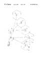
- FIG. 1is a block diagram of a wireless prior art system
- FIG. 2illustrates the beam coverage area in a prior art sectored cell for 3 antennas
- FIG. 3illustrates the beam coverage in a proposed prior art four antenna narrow beam coverage of a 120 degree cell sector
- FIG. 4illustrates the beam coverage in the present invention using an umbrella beam control signal antenna in combination with four narrow traffic beam antennas to provide coverage of a 120 degree cell sector;
- FIG. 5illustrates an umbrella control signal and multiple traffic signal antenna configuration for an entire cell
- FIG. 6comprises a chart used in explaining the assignment of traffic frequency antennas to an MS in an IS-54 system embodiment of the invention.
- a mobile switching center (MSC) 10is shown connected to a cloud 12 representing the public switched telephone network (PSTN) as well as being connected to a pair of base station controllers (BSC) 14 and 16 .
- BSC 14is connected to a pair of base transceiver stations (BTS) 18 and 20 .
- BSC 16is shown connected to a plurality of BTSs 22 , 24 , and 26 .
- BTSbase transceiver stations
- BSC 16is shown connected to a plurality of BTSs 22 , 24 , and 26 .
- Surrounding each BTSthere is a hexagon representing a cell or the area of radio coverage area of one or more antennas associated with the BTS.
- the hexagon cell around BTS 18is labeled 28 .
- Within cell 28are shown two mobile stations (MSs) 32 and 33 .
- the cell traffic capacitymay be increased by dividing the cell into sectors through the use of additional antennas.
- a common practiceis to use 3 antennas to cover an area such as a cell labeled 30 surrounding BTS 20 .
- the three sectors within cell 30are labeled X, Y, and Z.
- FIG. 2illustrates in more detail cell 30 of FIG. 1.
- a short dash line 32is representative of the actual area covered by radio waves transmitted by an antenna for sector X which may be reliably received by an MS.
- a long dash line 34encloses the sector Z and represents the sector coverage area of a second antenna. As may be noted there is an area of overlap of antenna coverage at the boundary of a sector.
- a solid line 36represents the reliable coverage area of an antenna for sector Y. Thus the coverage of sector or line 36 overlaps both sectors 32 and 34 .
- An MS 38is shown in the overlap region of sectors 32 and 34 (X and Z). When MS 38 is transmitting, the antenna for both of these sectors are likely to receive the signal at substantially the same signal strength.
- the antenna for sector Ymay also receive signals transmitted by MS 38 .
- a further MS 40is shown substantially centered within sector X.
- the antenna for sector Xwill receive the strongest signal and both of the antennas for sectors Y, and Z will receive reduced amplitude but substantially equal strength signals.
- Logic circuitrymay thus be used within BTS 20 to determine which antenna should be used to communicate with an MS based upon relative signal strength. The same logic may be used when an MS is in an overlap zone, as is MS 38 , so that the MS may be handed off from one antenna to another in the same cell.
- FIG. 3Cell X shows 3 overlapping beams A, B, C, and D each generated by separate antennas. Each of these beams would have an assigned set of traffic frequencies for use by MSs and a control frequency for assigning traffic frequencies, channel of an assigned frequency, handover channels, and so forth.
- this approach to solving cell capacity problemshas not been actively pursued because the large number of frequencies used for control severely limits the number of frequencies available for traffic signals.
- FIG. 4is similar to FIG. 3 but is distinguished by labeling a BTS as 40 and the cell generated by BTS 40 as cell 42 .
- BTS 40uses 5 antennas (not shown) for sector X.
- Traffic signal beams A, B, C, and Doperate to cover the entire sector with 4 of the antennas.
- the fifth antennais used to provide a control channel beam covering the entire sector and is labeled in the drawing as beam U.
- Beam Umay be categorized as an umbrella beam in that it covers the same total area as the 4 antennas generating traffic beams covering the sector X.
- Sectors Y, and Zmay operate in conventional fashion wherein each has a single antenna for both control and traffic signals.
- one or both of sectors Y, and Zmay have multiple antennas with one antenna operating to provide an umbrella control beam for that sector and the remaining antennas providing narrow traffic beam radio signal coverage.
- Each of the sectorsmay have a different number of narrow traffic beams if so desired.
- only three control frequenciesare required to control the operation of MSs operating within a 3 sectored cell shown even though there are many more than 3 narrow beam antennas providing traffic signals.
- a single structuremay be used as antenna means to generate a plurality of beams wherein each beam is a different frequency and covers a different area.
- the term “a plurality of antennas”may include a single structure for generating multiple beams covering different areas.
- At least one diversity path antennamay be utilized, in addition to a main path antenna, for each signal being transmitted to and received from an MS by a BTS.
- an area such as Bis intended to show illustratively an area of reliable reception of signal.
- the area covered by radio waves from an antenna structure that can be detected by an MSis likely to be much greater than that shown.
- a directional or beam forming antennacan not only transmit and receive signals in the forward direction, but can do transmit and receive signals from the back side although at a much lower signal strength or sensitivity.
- FIG. 5illustrates the invention using a single umbrella beam U for an entire cell generated by a control beam antenna of a BTS 50 where the single control signal is used to control all MSs actions communicating with BTS 50 via traffic signals generated over each of the sector beam antennas for sectors X, Y, and Z.
- a sector beam such as X in FIG. 5may be considered a narrow beam as compared to the umbrella beam U.
- each narrow beam antennatransmits one traffic or voice frequency of those frequencies assigned by the system to that antenna at a constant power level.
- These constant power level signalsmay be termed “beacon” signals.
- the umbrella antennabroadcasts on the DCCH to all MSs in the coverage area, a list of those beacon frequencies which are included in the MACA list.
- each MSsupplies information relative to the downlink signal strengths of all the listed MACA frequencies (the beacon frequencies). This use of this information is slightly different from that in prior art systems which used the information solely to determine the best frequency traffic channel to use with a given antenna.
- the present inventionuses the information to determine the antenna that is forming the specific narrow beam within which the MS is located since the signal strength of that beam should be the greatest and the adjacent traffic beams should provide the second highest detected signal strengths.
- an MSis, for example, in beam B between the edges of the overlapping portions of beams A and C if the MS reports that the downlink signal strength of beacon B as seen by the MS is substantially stronger than beacons A and C. If on the other hand, the report is that beacon signals A and B are substantially the same strength, it may logically be assumed that the MS is located in a area on the edge of beacon B where beacon A overlaps. In either event, it is likely that the system would instruct the MS to use one of the frequencies that is assigned to the portion of the system using antenna B.
- the MSmay well be instructed to use a frequency available to antenna A.
- An alternative assignment of channels, when a given antenna is already overloaded,is to temporarily use one of the traffic channels of the umbrella beam.
- a similar analysis of operationmay be for an MS located in the coverage area of other beacons. If an MS is located in the area of coverage near the edge of a sector, such as in beacon A, the MACA list may also include an appropriate signal frequency from a signal in the adjacent sector Z for use in determining when an MS needs to be handed over to an adjacent sector.
- the inventionmay be used to reduce the number of control channels in a cell to one by adding an omnidirectional antenna to provide an umbrella control channel beam for control of all MSs in any of the sectors of the cell in a manner directly analogous to that described in connection with FIG. 4 .
- the digital control channel (DCCH) frequency signal in present day IS-136 compliant systemscomprises one control channel and two traffic (voice) channels.
- These traffic channelsmay be used in both of the embodiments of FIGS. 4 and 5 to temporarily provide communication to MSs being handed off from neighboring cells until a determination may be made as to the strongest beacon frequency being received by the handed off MS. Once such a determination is made, the MS is assigned a channel appropriate to the antenna forming that beacon frequency signal.
- Mobilesare served by channels on the umbrella beam only until such time as they can be handed down to one of the narrow beams. This is because it is advantageous, from an RF interference point of view, to use a narrow beam to serve a call rather than the umbrella beam.
- the umbrella beamWhen the present invention is implemented in an IS-54 compliant system, the umbrella beam will comprise an analog control channel (ACCH) and a small number of voice channels.
- the umbrella beam for an IS-54 systemmay be similar in usage to that of a DCCH frequency beam which includes two traffic channels. All origination messages and page responses from an MS will be handled by the voice channels in the umbrella beam in an IS-54 system, since there is no means of determining the best server beam for a mobile at call setup time.
- the mobile transmissionsOnce the call is set up on a channel on the umbrella beam, the mobile transmissions will be received by all of the narrow beam antennas as well as by one or more antennas in adjacent sectors when using the configuration of FIG. 4 .
- the relative signal strengths of the signals as received by the various antennas of the BTSmay be used to logically determine the appropriate antenna to be used to serve the MS and the call is then handed down.
- Radio signal receivers made by some manufacturers for cellular equipmentinclude inputs from various antennas. These multiple inputs are useful for receiving diversity signals as well as determining the location of an MS for handover of an MS from one sector of a cell to an adjacent sector.
- the chart of FIG. 6illustrates one possible set of connections that may be made with respect to receivers operating in the X sector of FIG. 4 .
- a receiverthat is used to receive traffic frequency signals of a given frequency from an MS in beam A receives signals from the main A beacon antenna at port 1 .
- At port 2it receives any component of the signal at the given frequency that might be picked up by a diversity antenna in the Z sector (Z(D)).
- Any components of signal at said given frequency as detected at a Y sector main antenna (a rear area of the A beacon antenna)are supplied to port 3 .
- Given frequency signals detected by a diversity antenna for beacon Aare supplied to port 4 while those signals detected by a main antenna used by beacon B are supplied to port 5 .
- a further rear area inputis provided at port 6 from a main antenna in sector Z.
- Port 2For each of the radio receivers operating in conjunction with the A, B, C, and D beacon antenna, Port 2 comprises signals received from an antenna located to the left of the main antenna while port 5 comprises signals received from an antenna located to the right of the main antenna.
- the receiver operating to receive signals from the umbrella beam X antennais connected somewhat differently in that ports 2 , 3 , 5 , and 6 are connected to receive inputs from the main antennas from beacons A, B, C, and D respectively. Similar logic to that used to determine the location of an MS for handover purposes may be utilized to determine the location of an MS for initial frequency assignment purposes.
- the relative signal strengths as received at the ports 2 , 3 , 5 , and 6may be compared to determine the location of the MS in question. If the signal transmitted from the MS is received at the highest amplitude at port 3 , the MS is probably located within the area of beacon B and between the extremes of beacons A and C. Accordingly, the MS is assigned a traffic signal channel selected from a set of frequencies to be used in conjunction with the antenna transmitting beacon B. If, on the other hand, the signals received at ports 2 and 3 are substantially equal, the Ms is likely located in the overlapping area of beacons A and B. If past history as to the direction of movement of the MS is available, it may be used in determining the frequency assignment. Also, in such a case, an assignment frequency may be made on the basis of available capacity of antenna A for additional traffic relative antenna B.
- the present inventioncomprises the use of an umbrella antenna for control such as signal assignment and handover in conjunction with a plurality of traffic frequency antennas each covering a unique portion of the area covered by the umbrella antenna whereby system capacity is increased while reducing signal channels devoted to control.
Landscapes
- Engineering & Computer Science (AREA)
- Computer Networks & Wireless Communication (AREA)
- Signal Processing (AREA)
- Mobile Radio Communication Systems (AREA)
Abstract
Description
Claims (10)
Priority Applications (3)
| Application Number | Priority Date | Filing Date | Title |
|---|---|---|---|
| US09/321,517US6597927B1 (en) | 1999-05-27 | 1999-05-27 | Narrow beam traffic channel assignment method and apparatus |
| CA002305120ACA2305120A1 (en) | 1999-05-27 | 2000-04-12 | Narrow beam traffic channel assignment method and apparatus |
| EP00304472AEP1056304A3 (en) | 1999-05-27 | 2000-05-25 | Narrow beam traffic channel assignment method and apparatus |
Applications Claiming Priority (1)
| Application Number | Priority Date | Filing Date | Title |
|---|---|---|---|
| US09/321,517US6597927B1 (en) | 1999-05-27 | 1999-05-27 | Narrow beam traffic channel assignment method and apparatus |
Publications (1)
| Publication Number | Publication Date |
|---|---|
| US6597927B1true US6597927B1 (en) | 2003-07-22 |
Family
ID=23250930
Family Applications (1)
| Application Number | Title | Priority Date | Filing Date |
|---|---|---|---|
| US09/321,517Expired - LifetimeUS6597927B1 (en) | 1999-05-27 | 1999-05-27 | Narrow beam traffic channel assignment method and apparatus |
Country Status (3)
| Country | Link |
|---|---|
| US (1) | US6597927B1 (en) |
| EP (1) | EP1056304A3 (en) |
| CA (1) | CA2305120A1 (en) |
Cited By (34)
| Publication number | Priority date | Publication date | Assignee | Title |
|---|---|---|---|---|
| US20020058514A1 (en)* | 2000-11-10 | 2002-05-16 | Nortel Networks Limited | Multibeam wireless communications method and system including an interference avoidance scheme in which the area of each transmitted beam is divided into a plurality of sub-areas |
| US20020086708A1 (en)* | 2000-12-29 | 2002-07-04 | Teo Koon Hoo | Apparatus and method for OFDM data communications |
| US20020128027A1 (en)* | 2001-03-09 | 2002-09-12 | Wong Piu Bill | System and method for providing phase matching with optimized beam widths |
| US20030114165A1 (en)* | 2001-12-07 | 2003-06-19 | Mills Donald Charles | Method for enhanced wireless signal distribution |
| US20030148764A1 (en)* | 2002-02-07 | 2003-08-07 | Kelley Sean S. | Method and apparatus for band class acquisition and assignment in a wireless communication system |
| US6654609B2 (en)* | 1999-12-02 | 2003-11-25 | Hyundai Electronics Industries Co., Ltd. | Method for measuring location of mobile station and for performing handoff using the same in mobile communication system |
| US20040032840A1 (en)* | 2000-12-07 | 2004-02-19 | Qing Zhu | Method for direct retrying based on macro diversity in CDMA system |
| US20040048635A1 (en)* | 2002-09-09 | 2004-03-11 | Interdigital Technology Corporation | Vertical dynamic beam-forming |
| US20040077379A1 (en)* | 2002-06-27 | 2004-04-22 | Martin Smith | Wireless transmitter, transceiver and method |
| US20040127230A1 (en)* | 2002-12-27 | 2004-07-01 | David Bevan | Angle of arrival estimation in a wireless telecommunications network |
| US6771987B1 (en)* | 1999-10-28 | 2004-08-03 | Telefonaktiebolaget Lm Ericsson (Publ) | Method and apparatus for uplink scheduling |
| US20050026567A1 (en)* | 2001-04-24 | 2005-02-03 | Mark Austin | Wireless frequency re-use determination systems and methods |
| US20050038660A1 (en)* | 2001-09-12 | 2005-02-17 | Black Sarah Leslie | Device for providing voice driven control of a media presentation |
| US20050085270A1 (en)* | 2003-10-17 | 2005-04-21 | Sobczak David M. | Wireless antenna traffic matrix |
| US20050136932A1 (en)* | 2002-02-28 | 2005-06-23 | Mokoto Nagai | Radio apparatus, radio communication system, spatial path control method and spatial path control program |
| US20060072501A1 (en)* | 1999-12-15 | 2006-04-06 | Kabushiki Kaisha Toshiba | Radio communication scheme |
| US20060183503A1 (en)* | 2002-09-09 | 2006-08-17 | Interdigital Technology Corporation | Reducing the effect of signal interference in null areas caused by overlapping antenna patterns |
| US7133380B1 (en)* | 2000-01-11 | 2006-11-07 | At&T Corp. | System and method for selecting a transmission channel in a wireless communication system that includes an adaptive array |
| US7142580B1 (en)* | 2000-10-24 | 2006-11-28 | Ericsson, Inc. | Systems, methods, and computer program products for providing traffic frequency diversification in a cellular communication system |
| US20070070957A1 (en)* | 2005-09-23 | 2007-03-29 | Wayout Wireless, Llc | Multiple beam antenna base station |
| US20070135170A1 (en)* | 2005-12-09 | 2007-06-14 | Samsung Electronics Co., Ltd. | Flexible sectorization in wireless communication systems |
| US20070197182A1 (en)* | 2000-10-20 | 2007-08-23 | Masaya Umemura | Radio equipment |
| US20080261658A1 (en)* | 2007-04-18 | 2008-10-23 | Cisco Technology, Inc. | Hybrid Time-Spatial Multiplexing for Wireless Broadcast Messages through Antenna Radiation Beam Synthesis |
| US20080274748A1 (en)* | 2003-07-03 | 2008-11-06 | Rotani, Inc. | Methods and Apparatus for Channel Assignment |
| US20090274130A1 (en)* | 2006-09-27 | 2009-11-05 | Dragonwave, Inc. | Wireless network communication apparatus, methods, and integrated antenna structures |
| US20100081439A1 (en)* | 2008-09-29 | 2010-04-01 | Qualcomm Incorporated | Dynamic sectors in a wireless communication system |
| US20100120415A1 (en)* | 2008-11-12 | 2010-05-13 | Nortel Networks Limited | Antenna auto-configuration |
| US8300594B1 (en)* | 2005-10-20 | 2012-10-30 | Avaya Inc. | Method and apparatus supporting out of band signaling for WLAN using network name |
| US20140194129A1 (en)* | 2013-01-04 | 2014-07-10 | The Boeing Company | Staggered Cells For Wireless Coverage |
| US20160323803A1 (en)* | 2015-04-30 | 2016-11-03 | Mist Systems, Inc. | Methods and apparatus relating to the use of real and/or virtual beacons |
| US9496930B2 (en) | 2006-02-28 | 2016-11-15 | Woodbury Wireless, LLC | Methods and apparatus for overlapping MIMO physical sectors |
| US9503907B2 (en) | 2013-02-13 | 2016-11-22 | The Boeing Company | Overlapping cells for wireless coverage |
| US10396880B2 (en)* | 2014-02-06 | 2019-08-27 | Telefonaktiebolaget Lm Ericsson (Publ) | Beam-forming selection |
| US10932141B2 (en) | 2015-04-30 | 2021-02-23 | Juniper Networks, Inc. | Methods and apparatus for generating,transmitting and/or using beacons |
Families Citing this family (13)
| Publication number | Priority date | Publication date | Assignee | Title |
|---|---|---|---|---|
| US7340279B2 (en)* | 2001-03-23 | 2008-03-04 | Qualcomm Incorporated | Wireless communications with an adaptive antenna array |
| SE0201102D0 (en)* | 2002-04-10 | 2002-04-10 | Ericsson Telefon Ab L M | Method in a communication network |
| US20070274403A1 (en)* | 2003-12-22 | 2007-11-29 | Sung-Cheol Chang | Method for Constituting Layered Cell in Ofdma System |
| GB2414631B (en)* | 2004-05-26 | 2006-12-13 | Motorola Inc | A wireless communications network and method of operation thereof |
| WO2006004462A1 (en)* | 2004-06-30 | 2006-01-12 | Telefonaktiebolaget Lm Ericsson (Publ) | Data processing in intra-site handover |
| US7720036B2 (en) | 2005-10-26 | 2010-05-18 | Intel Corporation | Communication within a wireless network using multiple frequency bands |
| US7653163B2 (en) | 2005-10-26 | 2010-01-26 | Intel Corporation | Systems for communicating using multiple frequency bands in a wireless network |
| US9084260B2 (en) | 2005-10-26 | 2015-07-14 | Intel Corporation | Systems for communicating using multiple frequency bands in a wireless network |
| US8340071B2 (en) | 2005-10-26 | 2012-12-25 | Intel Corporation | Systems for communicating using multiple frequency bands in a wireless network |
| US20070099669A1 (en)* | 2005-10-26 | 2007-05-03 | Sadri Ali S | Communication signaling using multiple frequency bands in a wireless network |
| US7689171B2 (en) | 2006-11-27 | 2010-03-30 | Intel Corporation | Reducing interference in a wireless network via antenna selection |
| EP2227056B1 (en)* | 2009-03-02 | 2019-04-24 | Alcatel Lucent | Method for enhancing the handover of a mobile station and base station for carrying out the method |
| EP2481246B1 (en)* | 2009-09-24 | 2017-11-08 | Telefonaktiebolaget LM Ericsson (publ) | Method and arrangement in a telecommunication system |
Citations (17)
| Publication number | Priority date | Publication date | Assignee | Title |
|---|---|---|---|---|
| US4144496A (en)* | 1976-03-17 | 1979-03-13 | Harris Corporation | Mobile communication system and method employing frequency reuse within a geographical service area |
| US4144412A (en)* | 1976-01-19 | 1979-03-13 | Nippon Telegraph And Telephone Public Corporation | Method of assigning a radio channel to a calling mobile body of mobile communication system and radio channel assigning system therefor |
| US4723266A (en)* | 1987-01-21 | 1988-02-02 | General Electric Company | Cellular communication system sharing control channels between cells to reduce number of control channels |
| US5357559A (en)* | 1991-12-12 | 1994-10-18 | Telefonaktiebolaget L M Ericsson | Listening control channel in a cellular mobile radiotelephone system |
| WO1996009733A2 (en) | 1994-09-19 | 1996-03-28 | Nokia Telecommunications Oy | Base station |
| US5535423A (en)* | 1993-05-28 | 1996-07-09 | Societe Anonyme Dite Alcatel Radiotelephone | Method of exchanging data between a base transceiver station of a mobile radio network and a mobile in the network |
| US5546443A (en)* | 1992-10-26 | 1996-08-13 | Ericsson Ge Mobile Communications, Inc. | Communication management technique for a radiotelephone system including microcells |
| US5548807A (en)* | 1993-10-07 | 1996-08-20 | Nec Corporation | Mobile communication system comprising base stations each having omnidirectional antenna for reception of interference wave |
| US5596333A (en)* | 1994-08-31 | 1997-01-21 | Motorola, Inc. | Method and apparatus for conveying a communication signal between a communication unit and a base site |
| US5615409A (en)* | 1993-09-27 | 1997-03-25 | Telefonaktiebolaget Lm Ericsson | Method and apparatus for transmitting and receiving signals using two classes of channels |
| EP0797369A2 (en) | 1996-03-21 | 1997-09-24 | Ntt Mobile Communications Network Inc. | CDMA mobile communication scheme with effective use of sector configuration |
| DE19747365A1 (en) | 1997-10-27 | 1999-04-29 | Siemens Ag | Organisation information transmission method for radio communication system |
| US6141566A (en)* | 1999-01-11 | 2000-10-31 | Tellabs Operations, Inc. | Co-located omnidirectional and sectorized base station |
| US6161024A (en)* | 1998-10-15 | 2000-12-12 | Airnet Communications Corporations | Redundant broadband multi-carrier base station for wireless communications using omni-directional overlay on a tri-sectored wireless system |
| US6167286A (en)* | 1997-06-05 | 2000-12-26 | Nortel Networks Corporation | Multi-beam antenna system for cellular radio base stations |
| US6240290B1 (en)* | 1999-03-04 | 2001-05-29 | Harris Corporation | Base station hand-off mechanism for cellular communication system |
| US6301238B1 (en)* | 1997-01-28 | 2001-10-09 | Telefonaktiebolaget Lm Ericsson (Publ) | Directional-beam generative apparatus and associated method |
- 1999
- 1999-05-27USUS09/321,517patent/US6597927B1/ennot_activeExpired - Lifetime
- 2000
- 2000-04-12CACA002305120Apatent/CA2305120A1/ennot_activeAbandoned
- 2000-05-25EPEP00304472Apatent/EP1056304A3/ennot_activeWithdrawn
Patent Citations (18)
| Publication number | Priority date | Publication date | Assignee | Title |
|---|---|---|---|---|
| US4144412A (en)* | 1976-01-19 | 1979-03-13 | Nippon Telegraph And Telephone Public Corporation | Method of assigning a radio channel to a calling mobile body of mobile communication system and radio channel assigning system therefor |
| US4144496A (en)* | 1976-03-17 | 1979-03-13 | Harris Corporation | Mobile communication system and method employing frequency reuse within a geographical service area |
| US4723266A (en)* | 1987-01-21 | 1988-02-02 | General Electric Company | Cellular communication system sharing control channels between cells to reduce number of control channels |
| US5357559A (en)* | 1991-12-12 | 1994-10-18 | Telefonaktiebolaget L M Ericsson | Listening control channel in a cellular mobile radiotelephone system |
| US5546443A (en)* | 1992-10-26 | 1996-08-13 | Ericsson Ge Mobile Communications, Inc. | Communication management technique for a radiotelephone system including microcells |
| US5535423A (en)* | 1993-05-28 | 1996-07-09 | Societe Anonyme Dite Alcatel Radiotelephone | Method of exchanging data between a base transceiver station of a mobile radio network and a mobile in the network |
| US5615409A (en)* | 1993-09-27 | 1997-03-25 | Telefonaktiebolaget Lm Ericsson | Method and apparatus for transmitting and receiving signals using two classes of channels |
| US5548807A (en)* | 1993-10-07 | 1996-08-20 | Nec Corporation | Mobile communication system comprising base stations each having omnidirectional antenna for reception of interference wave |
| US5596333A (en)* | 1994-08-31 | 1997-01-21 | Motorola, Inc. | Method and apparatus for conveying a communication signal between a communication unit and a base site |
| WO1996009733A2 (en) | 1994-09-19 | 1996-03-28 | Nokia Telecommunications Oy | Base station |
| EP0797369A2 (en) | 1996-03-21 | 1997-09-24 | Ntt Mobile Communications Network Inc. | CDMA mobile communication scheme with effective use of sector configuration |
| US6011787A (en)* | 1996-03-21 | 2000-01-04 | Ntt Mobile Communications Network Inc. | CDMA mobile communication scheme with effective use of sector configuration |
| US6301238B1 (en)* | 1997-01-28 | 2001-10-09 | Telefonaktiebolaget Lm Ericsson (Publ) | Directional-beam generative apparatus and associated method |
| US6167286A (en)* | 1997-06-05 | 2000-12-26 | Nortel Networks Corporation | Multi-beam antenna system for cellular radio base stations |
| DE19747365A1 (en) | 1997-10-27 | 1999-04-29 | Siemens Ag | Organisation information transmission method for radio communication system |
| US6161024A (en)* | 1998-10-15 | 2000-12-12 | Airnet Communications Corporations | Redundant broadband multi-carrier base station for wireless communications using omni-directional overlay on a tri-sectored wireless system |
| US6141566A (en)* | 1999-01-11 | 2000-10-31 | Tellabs Operations, Inc. | Co-located omnidirectional and sectorized base station |
| US6240290B1 (en)* | 1999-03-04 | 2001-05-29 | Harris Corporation | Base station hand-off mechanism for cellular communication system |
Cited By (86)
| Publication number | Priority date | Publication date | Assignee | Title |
|---|---|---|---|---|
| US9681453B2 (en) | 1997-04-30 | 2017-06-13 | At&T Intellectual Property Ii, L.P. | System and method for selecting a transmission channel in a wireless communication system that includes an adaptive array |
| US10098128B2 (en) | 1997-04-30 | 2018-10-09 | At&T Intellectual Property Ii, L.P. | System and method for selecting a transmission channel in a wireless communication system that includes an adaptive antenna array |
| US6771987B1 (en)* | 1999-10-28 | 2004-08-03 | Telefonaktiebolaget Lm Ericsson (Publ) | Method and apparatus for uplink scheduling |
| US6654609B2 (en)* | 1999-12-02 | 2003-11-25 | Hyundai Electronics Industries Co., Ltd. | Method for measuring location of mobile station and for performing handoff using the same in mobile communication system |
| US7436800B2 (en)* | 1999-12-15 | 2008-10-14 | Kabushiki Kaisha Toshiba | Radio communication scheme |
| US20060072501A1 (en)* | 1999-12-15 | 2006-04-06 | Kabushiki Kaisha Toshiba | Radio communication scheme |
| US8036164B1 (en)* | 2000-01-11 | 2011-10-11 | At&T Intellectual Property Ii, L.P. | System and method for selecting a transmission channel in a wireless communication system that includes an adaptive array |
| US8855081B2 (en) | 2000-01-11 | 2014-10-07 | At&T Intellectual Property Ii, L.P. | System and method for selecting a transmission channel in a wireless communication system that includes an adaptive array |
| US7133380B1 (en)* | 2000-01-11 | 2006-11-07 | At&T Corp. | System and method for selecting a transmission channel in a wireless communication system that includes an adaptive array |
| US7904046B2 (en)* | 2000-10-20 | 2011-03-08 | Hitachi, Ltd. | Radio equipment having an attenuator between antenna and radio module |
| US20070197182A1 (en)* | 2000-10-20 | 2007-08-23 | Masaya Umemura | Radio equipment |
| US7142580B1 (en)* | 2000-10-24 | 2006-11-28 | Ericsson, Inc. | Systems, methods, and computer program products for providing traffic frequency diversification in a cellular communication system |
| US6907271B2 (en)* | 2000-11-10 | 2005-06-14 | Nortel Networks Limited | Multibeam wireless communications method and system including an interference avoidance scheme in which the area of each transmitted beam is divided into a plurality of sub-areas |
| US20020058514A1 (en)* | 2000-11-10 | 2002-05-16 | Nortel Networks Limited | Multibeam wireless communications method and system including an interference avoidance scheme in which the area of each transmitted beam is divided into a plurality of sub-areas |
| US20030008654A9 (en)* | 2000-11-10 | 2003-01-09 | Nortel Networks Limited | Multibeam wireless communications method and system including an interference avoidance scheme in which the area of each transmitted beam is divided into a plurality of sub-areas |
| US20040032840A1 (en)* | 2000-12-07 | 2004-02-19 | Qing Zhu | Method for direct retrying based on macro diversity in CDMA system |
| US6990346B2 (en)* | 2000-12-07 | 2006-01-24 | Huawei Technologies Co., Ltd. | Method for direct retrying based on macro diversity in CDMA system |
| US6996418B2 (en)* | 2000-12-29 | 2006-02-07 | Nortel Networks Limited | Apparatus and method for OFDM data communications |
| US20020086708A1 (en)* | 2000-12-29 | 2002-07-04 | Teo Koon Hoo | Apparatus and method for OFDM data communications |
| US20020128027A1 (en)* | 2001-03-09 | 2002-09-12 | Wong Piu Bill | System and method for providing phase matching with optimized beam widths |
| US6847832B2 (en)* | 2001-03-09 | 2005-01-25 | Kathrein-Werke Kg | System and method for providing phase matching with optimized beam widths |
| US20070087742A1 (en)* | 2001-04-24 | 2007-04-19 | Mark Austin | Wireless frequency re-use determination systems and methods |
| US7149479B2 (en)* | 2001-04-24 | 2006-12-12 | Bellsouth Intellectual Property Corp. | Wireless frequency re-use determination systems |
| US20050026567A1 (en)* | 2001-04-24 | 2005-02-03 | Mark Austin | Wireless frequency re-use determination systems and methods |
| US8103280B2 (en) | 2001-04-24 | 2012-01-24 | At&T Intellectual Property I, Lp | Wireless frequency re-use determination systems and methods |
| US20080049664A1 (en)* | 2001-04-24 | 2008-02-28 | Mark Austin | Wireless frequency re-use determination systems and methods |
| US7280814B2 (en)* | 2001-04-24 | 2007-10-09 | At&T Bls Intellectual Property, Inc. | Wireless frequency re-use determination systems and methods |
| US20050038660A1 (en)* | 2001-09-12 | 2005-02-17 | Black Sarah Leslie | Device for providing voice driven control of a media presentation |
| US20030114165A1 (en)* | 2001-12-07 | 2003-06-19 | Mills Donald Charles | Method for enhanced wireless signal distribution |
| US6721562B2 (en)* | 2002-02-07 | 2004-04-13 | Motorola, Inc. | Method and apparatus for band class acquisition and assignment in a wireless communication system |
| WO2003067903A3 (en)* | 2002-02-07 | 2004-02-12 | Motorola Inc | Method and apparatus for band class acquisition and assignment in a wireless communication system |
| US20030148764A1 (en)* | 2002-02-07 | 2003-08-07 | Kelley Sean S. | Method and apparatus for band class acquisition and assignment in a wireless communication system |
| US7184773B2 (en)* | 2002-02-28 | 2007-02-27 | Sanyo Electric Co., Ltd. | Spatial path control in radio communication system |
| US20050136932A1 (en)* | 2002-02-28 | 2005-06-23 | Mokoto Nagai | Radio apparatus, radio communication system, spatial path control method and spatial path control program |
| US20040077379A1 (en)* | 2002-06-27 | 2004-04-22 | Martin Smith | Wireless transmitter, transceiver and method |
| US7831280B2 (en) | 2002-09-09 | 2010-11-09 | Interdigital Technology Corporation | Reducing the effect of signal interference in null areas caused by overlapping antenna patterns |
| US7245939B2 (en) | 2002-09-09 | 2007-07-17 | Interdigital Technology Corporation | Reducing the effect of signal interference in null areas caused by overlapping antenna patterns |
| US20070249405A1 (en)* | 2002-09-09 | 2007-10-25 | Interdigital Technology Corporation | Reducing the effect of signal interference in null areas caused by overlapping antenna patterns |
| US20040048635A1 (en)* | 2002-09-09 | 2004-03-11 | Interdigital Technology Corporation | Vertical dynamic beam-forming |
| US7236808B2 (en)* | 2002-09-09 | 2007-06-26 | Interdigital Technology Corporation | Vertical dynamic beam-forming |
| US20060183503A1 (en)* | 2002-09-09 | 2006-08-17 | Interdigital Technology Corporation | Reducing the effect of signal interference in null areas caused by overlapping antenna patterns |
| US7092673B2 (en)* | 2002-12-27 | 2006-08-15 | Nortel Networks Limited | Angle of arrival estimation in a wireless telecommunications network |
| US20040127230A1 (en)* | 2002-12-27 | 2004-07-01 | David Bevan | Angle of arrival estimation in a wireless telecommunications network |
| US7873319B2 (en) | 2003-07-03 | 2011-01-18 | Rotani, Inc. | Methods and apparatus for channel assignment |
| US20080274748A1 (en)* | 2003-07-03 | 2008-11-06 | Rotani, Inc. | Methods and Apparatus for Channel Assignment |
| US20050085270A1 (en)* | 2003-10-17 | 2005-04-21 | Sobczak David M. | Wireless antenna traffic matrix |
| US7245938B2 (en)* | 2003-10-17 | 2007-07-17 | Sobczak David M | Wireless antenna traffic matrix |
| US20070070957A1 (en)* | 2005-09-23 | 2007-03-29 | Wayout Wireless, Llc | Multiple beam antenna base station |
| US8199724B2 (en)* | 2005-09-23 | 2012-06-12 | Xr Communications, Llc | Multiple beam antenna base station |
| US8300594B1 (en)* | 2005-10-20 | 2012-10-30 | Avaya Inc. | Method and apparatus supporting out of band signaling for WLAN using network name |
| US20070135170A1 (en)* | 2005-12-09 | 2007-06-14 | Samsung Electronics Co., Ltd. | Flexible sectorization in wireless communication systems |
| US8560018B2 (en)* | 2005-12-09 | 2013-10-15 | Samsung Electronics Co., Ltd. | Flexible sectorization in wireless communication systems |
| US9496931B2 (en) | 2006-02-28 | 2016-11-15 | Woodbury Wireless, LLC | Methods and apparatus for overlapping MIMO physical sectors |
| US10069548B2 (en) | 2006-02-28 | 2018-09-04 | Woodbury Wireless, LLC | Methods and apparatus for overlapping MIMO physical sectors |
| US12015457B2 (en) | 2006-02-28 | 2024-06-18 | Woodbury Wireless, LLC | MIMO methods and systems |
| US9584197B2 (en) | 2006-02-28 | 2017-02-28 | Woodbury Wireless, LLC | Methods and apparatus for overlapping MIMO physical sectors |
| US11108443B2 (en) | 2006-02-28 | 2021-08-31 | Woodbury Wireless, LLC | MIMO methods and systems |
| US10516451B2 (en) | 2006-02-28 | 2019-12-24 | Woodbury Wireless Llc | MIMO methods |
| US10211895B2 (en) | 2006-02-28 | 2019-02-19 | Woodbury Wireless Llc | MIMO methods and systems |
| US9525468B2 (en) | 2006-02-28 | 2016-12-20 | Woodbury Wireless, LLC | Methods and apparatus for overlapping MIMO physical sectors |
| US10063297B1 (en) | 2006-02-28 | 2018-08-28 | Woodbury Wireless, LLC | MIMO methods and systems |
| US9503163B2 (en) | 2006-02-28 | 2016-11-22 | Woodbury Wireless, LLC | Methods and apparatus for overlapping MIMO physical sectors |
| US9496930B2 (en) | 2006-02-28 | 2016-11-15 | Woodbury Wireless, LLC | Methods and apparatus for overlapping MIMO physical sectors |
| US8351987B2 (en) | 2006-09-27 | 2013-01-08 | Dragonwave, Inc. | Wireless network communication apparatus, methods, and integrated antenna structures |
| US20090274130A1 (en)* | 2006-09-27 | 2009-11-05 | Dragonwave, Inc. | Wireless network communication apparatus, methods, and integrated antenna structures |
| EP1919233B1 (en)* | 2006-11-06 | 2020-02-26 | Samsung Electronics Co., Ltd. | Flexible sectorization in wireless communication systems |
| US20080261658A1 (en)* | 2007-04-18 | 2008-10-23 | Cisco Technology, Inc. | Hybrid Time-Spatial Multiplexing for Wireless Broadcast Messages through Antenna Radiation Beam Synthesis |
| US8195240B2 (en)* | 2007-04-18 | 2012-06-05 | Cisco Technology, Inc. | Hybrid time-spatial multiplexing for wireless broadcast messages through antenna radiation beam synthesis |
| US20100081439A1 (en)* | 2008-09-29 | 2010-04-01 | Qualcomm Incorporated | Dynamic sectors in a wireless communication system |
| US8670778B2 (en)* | 2008-09-29 | 2014-03-11 | Qualcomm Incorporated | Dynamic sectors in a wireless communication system |
| US8934855B2 (en)* | 2008-11-12 | 2015-01-13 | Apple Inc. | Antenna auto-configuration |
| US20100120415A1 (en)* | 2008-11-12 | 2010-05-13 | Nortel Networks Limited | Antenna auto-configuration |
| US8965385B2 (en)* | 2013-01-04 | 2015-02-24 | The Boeing Company | Staggered cells for wireless coverage |
| EP2757820A3 (en)* | 2013-01-04 | 2014-12-17 | The Boeing Company | Staggered cells for wireless coverage |
| US20140194129A1 (en)* | 2013-01-04 | 2014-07-10 | The Boeing Company | Staggered Cells For Wireless Coverage |
| US9503907B2 (en) | 2013-02-13 | 2016-11-22 | The Boeing Company | Overlapping cells for wireless coverage |
| US10396880B2 (en)* | 2014-02-06 | 2019-08-27 | Telefonaktiebolaget Lm Ericsson (Publ) | Beam-forming selection |
| US20160323803A1 (en)* | 2015-04-30 | 2016-11-03 | Mist Systems, Inc. | Methods and apparatus relating to the use of real and/or virtual beacons |
| US10932141B2 (en) | 2015-04-30 | 2021-02-23 | Juniper Networks, Inc. | Methods and apparatus for generating,transmitting and/or using beacons |
| US11076341B2 (en) | 2015-04-30 | 2021-07-27 | Juniper Networks, Inc. | Methods and apparatus relating to the use of real and/or virtual beacons |
| US10536894B2 (en) | 2015-04-30 | 2020-01-14 | Mist Systems, Inc. | Methods and apparatus relating to the use of real and/or virtual beacons |
| US11368856B2 (en) | 2015-04-30 | 2022-06-21 | Juniper Networks, Inc. | Methods and apparatus for generating,transmitting and/or using beacons |
| US11564147B2 (en) | 2015-04-30 | 2023-01-24 | Juniper Networks, Inc. | Methods and apparatus relating to the use of real and/or virtual beacons |
| US10028199B2 (en)* | 2015-04-30 | 2018-07-17 | Mist Systems, Inc. | Methods and apparatus relating to the use of real and/or virtual beacons |
| US12047863B2 (en) | 2015-04-30 | 2024-07-23 | Juniper Networks, Inc. | Methods and apparatus relating to the use of real and/or virtual beacons |
| US12058535B2 (en) | 2015-04-30 | 2024-08-06 | Juniper Networks, Inc. | Methods and apparatus for generating, transmitting and/or using beacons |
Also Published As
| Publication number | Publication date |
|---|---|
| EP1056304A3 (en) | 2000-12-27 |
| CA2305120A1 (en) | 2000-11-27 |
| EP1056304A2 (en) | 2000-11-29 |
Similar Documents
| Publication | Publication Date | Title |
|---|---|---|
| US6597927B1 (en) | Narrow beam traffic channel assignment method and apparatus | |
| US5535423A (en) | Method of exchanging data between a base transceiver station of a mobile radio network and a mobile in the network | |
| US6449482B1 (en) | Creation of overlapping cells when using multi casting | |
| EP1159849B1 (en) | Preservation of cell borders at hand-off within a smart antenna cellular system | |
| RU2237363C2 (en) | Method and device for cell switching-over | |
| US5839070A (en) | System and method for hyperband cell interoperability in a cellular telecommunications network | |
| US6539227B1 (en) | Methods and systems for controlling hard and soft handoffs in radio communications systems | |
| CA2315100C (en) | Method and system for improving handoffs in cellular mobile radio systems | |
| US5577047A (en) | System and method for providing macrodiversity TDMA radio communications | |
| US5559866A (en) | Method of reuse through remote antenna and same channel cell division | |
| CN100477847C (en) | Improvements in or relating to distributed radio units | |
| US5161249A (en) | Sectored voice channels with rear lobe protection | |
| JP2008113467A (en) | Handover method and cellular communication system | |
| KR100440656B1 (en) | Wireless communication system | |
| US6594492B2 (en) | Anchor MSC information retrieval from a serving MSC following a completed inter-exchange handoff | |
| US5911122A (en) | Inter-exchange passing of hand-off related parameters | |
| WO1990003088A1 (en) | High capacity sectorized cellular communication system | |
| EP0986927B1 (en) | Directed retry for call setup | |
| WO2000051368A2 (en) | Smart antenna beam assignment at mobile station hand-off | |
| WO2000051367A2 (en) | Smart antenna beam assignment at mobile station call setup | |
| CA2241363A1 (en) | A method for accessing a microcell using analog control channels | |
| EP1153523B1 (en) | Methods and systems for controlling hard and soft handoffs in radio communication systems | |
| WO1998003031A2 (en) | Method and apparatus for inter-system handoff within a plural hyperband supporting cellular telephone network | |
| CA2362899A1 (en) | Method for antenna gain acquisition in a cellular system | |
| EP0967819B1 (en) | Method for handover in a cellular system |
Legal Events
| Date | Code | Title | Description |
|---|---|---|---|
| AS | Assignment | Owner name:NORTEL NETWORKS CORPORATION, CANADA Free format text:ASSIGNMENT OF ASSIGNORS INTEREST;ASSIGNORS:ESWARA, SRINIVAS;WILSON, KEITH S.;MCCARTHY, MICHAEL J.;REEL/FRAME:010003/0951;SIGNING DATES FROM 19990519 TO 19990521 | |
| AS | Assignment | Owner name:NORTEL NETWORKS LIMITED, CANADA Free format text:CHANGE OF NAME;ASSIGNOR:NORTEL NETWORKS CORPORATION;REEL/FRAME:011195/0706 Effective date:20000830 Owner name:NORTEL NETWORKS LIMITED,CANADA Free format text:CHANGE OF NAME;ASSIGNOR:NORTEL NETWORKS CORPORATION;REEL/FRAME:011195/0706 Effective date:20000830 | |
| STCF | Information on status: patent grant | Free format text:PATENTED CASE | |
| FEPP | Fee payment procedure | Free format text:PAYOR NUMBER ASSIGNED (ORIGINAL EVENT CODE: ASPN); ENTITY STATUS OF PATENT OWNER: LARGE ENTITY | |
| FPAY | Fee payment | Year of fee payment:4 | |
| FPAY | Fee payment | Year of fee payment:8 | |
| AS | Assignment | Owner name:ROCKSTAR BIDCO, LP, NEW YORK Free format text:ASSIGNMENT OF ASSIGNORS INTEREST;ASSIGNOR:NORTEL NETWORKS LIMITED;REEL/FRAME:027164/0356 Effective date:20110729 | |
| AS | Assignment | Owner name:APPLE INC., CALIFORNIA Free format text:ASSIGNMENT OF ASSIGNORS INTEREST;ASSIGNOR:ROCKSTAR BIDCO, LP;REEL/FRAME:028648/0778 Effective date:20120511 | |
| FPAY | Fee payment | Year of fee payment:12 |