US6597746B1 - System and method for peak to average power ratio reduction - Google Patents
System and method for peak to average power ratio reductionDownload PDFInfo
- Publication number
- US6597746B1 US6597746B1US09/505,528US50552800AUS6597746B1US 6597746 B1US6597746 B1US 6597746B1US 50552800 AUS50552800 AUS 50552800AUS 6597746 B1US6597746 B1US 6597746B1
- Authority
- US
- United States
- Prior art keywords
- digital
- filter
- output
- signal
- input
- Prior art date
- Legal status (The legal status is an assumption and is not a legal conclusion. Google has not performed a legal analysis and makes no representation as to the accuracy of the status listed.)
- Expired - Fee Related
Links
- 238000000034methodMethods0.000titleclaimsabstractdescription49
- 230000009467reductionEffects0.000titleabstractdescription6
- 238000007493shaping processMethods0.000claimsabstractdescription54
- 238000012937correctionMethods0.000claimsabstractdescription49
- 230000001364causal effectEffects0.000claimsabstractdescription14
- 230000004044responseEffects0.000claimsdescription20
- 238000012545processingMethods0.000claimsdescription16
- 230000006870functionEffects0.000claimsdescription10
- 230000008878couplingEffects0.000claimsdescription8
- 238000010168coupling processMethods0.000claimsdescription8
- 238000005859coupling reactionMethods0.000claimsdescription8
- 230000002596correlated effectEffects0.000claims4
- 230000005540biological transmissionEffects0.000abstractdescription29
- 238000013459approachMethods0.000abstractdescription13
- 230000008901benefitEffects0.000abstractdescription9
- 238000001914filtrationMethods0.000abstractdescription2
- 239000003638chemical reducing agentSubstances0.000description31
- 238000004891communicationMethods0.000description22
- 238000011144upstream manufacturingMethods0.000description10
- 238000010586diagramMethods0.000description9
- 238000011084recoveryMethods0.000description5
- 239000000243solutionSubstances0.000description5
- 238000006243chemical reactionMethods0.000description4
- 230000008569processEffects0.000description4
- 238000012546transferMethods0.000description4
- RYGMFSIKBFXOCR-UHFFFAOYSA-NCopperChemical compound[Cu]RYGMFSIKBFXOCR-UHFFFAOYSA-N0.000description3
- 229910052802copperInorganic materials0.000description3
- 239000010949copperSubstances0.000description3
- 230000000694effectsEffects0.000description3
- 238000012986modificationMethods0.000description3
- 230000004048modificationEffects0.000description3
- 238000005070samplingMethods0.000description3
- 230000008054signal transmissionEffects0.000description3
- 238000001228spectrumMethods0.000description3
- 230000003111delayed effectEffects0.000description2
- 230000001360synchronised effectEffects0.000description2
- 101100457839Schizosaccharomyces pombe (strain 972 / ATCC 24843) mod21 geneProteins0.000description1
- 230000009471actionEffects0.000description1
- 230000003044adaptive effectEffects0.000description1
- 239000000654additiveSubstances0.000description1
- 230000000996additive effectEffects0.000description1
- 230000008859changeEffects0.000description1
- 230000001186cumulative effectEffects0.000description1
- 230000001934delayEffects0.000description1
- 230000001419dependent effectEffects0.000description1
- 238000013461designMethods0.000description1
- 238000011143downstream manufacturingMethods0.000description1
- 238000005516engineering processMethods0.000description1
- 238000002347injectionMethods0.000description1
- 239000007924injectionSubstances0.000description1
- 238000003780insertionMethods0.000description1
- 230000037431insertionEffects0.000description1
- 230000002452interceptive effectEffects0.000description1
- 238000002955isolationMethods0.000description1
- 238000005457optimizationMethods0.000description1
- 239000002243precursorSubstances0.000description1
- 230000000644propagated effectEffects0.000description1
- 230000000306recurrent effectEffects0.000description1
- 230000003595spectral effectEffects0.000description1
- 230000009466transformationEffects0.000description1
- 238000013519translationMethods0.000description1
Images


Classifications
- H—ELECTRICITY
- H04—ELECTRIC COMMUNICATION TECHNIQUE
- H04L—TRANSMISSION OF DIGITAL INFORMATION, e.g. TELEGRAPHIC COMMUNICATION
- H04L25/00—Baseband systems
- H04L25/02—Details ; arrangements for supplying electrical power along data transmission lines
- H04L25/03—Shaping networks in transmitter or receiver, e.g. adaptive shaping networks
- H04L25/03006—Arrangements for removing intersymbol interference
- H04L25/03343—Arrangements at the transmitter end
- H—ELECTRICITY
- H04—ELECTRIC COMMUNICATION TECHNIQUE
- H04L—TRANSMISSION OF DIGITAL INFORMATION, e.g. TELEGRAPHIC COMMUNICATION
- H04L27/00—Modulated-carrier systems
- H04L27/26—Systems using multi-frequency codes
- H04L27/2601—Multicarrier modulation systems
- H04L27/2614—Peak power aspects
Definitions
- the present inventiongenerally relates to communication systems, and more particularly, to a system and method for peak to average power ratio reduction in communication systems using time domain techniques for data signal transmission.
- the present inventionis particularly suited to transmitters that use pulse amplitude modulation (PAM) and Tomlinson preceding.
- PAMpulse amplitude modulation
- POTS communicationsinclude the transmission of voice information, control signals, PSTN (public switched telephone network) information, as well as, information from ancillary equipment in analog form (i.e. computer modems and facsimile machines) that is transmitted in the POTS bandwidth.
- PSTNpublic switched telephone network
- DSLdigital subscriber line
- DMTdiscrete multi-tone
- ADSL systemscan be designed to operate over the same copper lines with either the POTS or a Basic Access Integrated Service Digital Network (ISDN-BA) service.
- ADSL systemsare designed to transmit significantly more data in the downstream direction, that is, from the telecommunication service provider to the remote customer, rather than sharing the bandwidth as in a dual-duplex communication system.
- the ADSL configurationpermits the concurrent transmission of multiple digital signals from the telecommunications service provider to a remote location, while providing an adequate bandwidth for the limited capacity required for data transmissions originating at the remote site.
- High-Bit-Rate digital subscriber linescan be considered an extension of the DSL and ADSL systems.
- HDSLwas developed as a dual-duplex repeaterless T1 technology.
- HDSLwas designed to serve non-load telephone subscriber loops meeting the Carrier Serving Area (CSA) guidelines.
- CSACarrier Serving Area
- ADSL systemsare designed to take advantage of the full data transmission capacity of a cable pair in both directions. It is important to note that ADSL systems use DMT modulation for data transmission. Conversely, HDSL systems use PAM, a broadband carrierless method, for data transmission.
- a HDSL transmission unit—central office (HTU-C)is configured to modulate and convert digital data for analog transmission from a central office downstream to a remotely located HDSL transmission unit—remote (HTU-R).
- HTU-Ccentral office
- HTU-Rremotely located HDSL transmission unit
- Each end of the HDSL link configured at the end points of a CSA loopis provided a similarly configured HDSL transmission unit.
- the central office and remote designators for the two HDSL transmission unitsis for descriptive purposes only as both units are interchangeable with the remote (HTU-R) unit configured to receive the analog transmission sent from the HTU-C from the telephone line.
- the HTU-Rdemodulates the signals and applies error correction before delivering each of the reconstructed digital data signals to its intended device. Concurrently, the HTU-R transmits data from the remote location back to the HTU-C.
- incoming data bitsare first encoded in PAM symbols, then subjected to Tomlinson preceding to better match the exact characteristics of the line.
- the encoded and modified PAM symbolsare then passed through a bandwidth shaping filter.
- Constraints on the average transmitted power in communication systemsvary according to the specific application. In DSL applications, constraints are imposed to limit the amount of interference, or crosstalk, radiated into neighboring receivers. Because crosstalk is frequency dependent, the constraint on average power may take the form of a spectral mask that specifies the magnitude of allowable transmitted power as a function of frequency. For example, crosstalk in POTS communication systems is generally caused by capacitive coupling and increases as a function of frequency. Consequently, to reduce the amount of crosstalk generated at a particular transmitter, the pulse shaping filter generally attenuates higher frequencies more than lower frequencies.
- the dynamic range of the transmitteris limited by its line driver and its digital to analog converter (DAC).
- DACdigital to analog converter
- saturation of the line driverwill “clip” the transmitted waveform.
- signal magnitudes that exceed the dynamic range of the DACwill also “clip” the transmitted waveform.
- the transmitted signalmay be subject to other non-clipping induced non-linearities.
- a major component of the total power consumption within a transmitteris consumed within the line driver, as line driver power consumption overwhelms the power consumed by digital signal processing. As a result, PAR reduction is important to decrease power consumption in the output line driver.
- the peak to average power ratiois defined as the ratio of the magnitude of the instantaneous peak power to the time averaged value of the power.
- the PARis defined by the digital transmit shaping filter.
- the shaping filteris added in the modulation stage within the HTUs to shape the spectrum of the transmitted signal.
- Minimizing transmitter power for a given data rate in a given bandwidthis a recurrent theme in designing communication systems. As such, a number of techniques have been developed. However, to date, PAR has been adjusted by modifying the modulation (or encoding) technique or by selecting a specific shaping filter.
- the present inventionprovides a system and method for reducing the peak to average power in a transmitter designed to use a broadband carrierless modulation scheme.
- the systemcan be implemented by introducing a comparator in a feedback loop of the causal portion of a digital shaping filter and introducing a correction signal in the feedback loop when the magnitude of encoded symbols exceeds a predetermined threshold.
- the corrected encoded signalsmay be processed by both the causal and residual portions of the digital shaping filter prior to digital to analog conversion.
- the system of the present inventionis particularly suited to systems that use Tomlinson preceding.
- the PAR reducermay be inserted to further modify the encoded symbols prior to digital to analog conversion.
- a predictionmay be made of the peak values that would be obtained if the original output of the Tomlinson precoder was proceesed by the shaping filter. If the absolute value of the predicted peak value exceeds a threshold, a correction of a full 2L step may be applied for one sample of the Tomlinson precoded symbol stream. The correction step is applied in such a way as to reduce the resulting peak output.
- the PAR reducer of the present inventionmay be implemented as a transmitter only solution.
- Two methods of predicting the peak valuesare presented, one splits the filter into causal and non-causal filter segments so that no extra delay is introduced in the process, the second method uses a two-pass approach where a first pass gives the exact values without correction, then the corrected values are injected in a duplicate modulation filter (this implies an extra delay equal to the filter delay). Note that an N-pass approach may be derived from the two-pass approach.
- a variation of the two-pass approachtakes advantage of the linearity of the system to estimate the correction. Since the modulation scheme is not completely linear, the variation of the two-pass implementation is an approximation of the other embodiments.
- FIG. 1is a diagram illustrating a pulse amplitude modulation (PAM) approach as may be applied on a transmission line.
- PAMpulse amplitude modulation
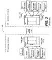
- FIG. 2is a block diagram illustrating delivery of multiple broadband services via a communications system on a twisted-pair telephone line.
- FIG. 3is a functional block diagram further illustrating a HDSL transmission unit as may be deployed in the HDSL line card of FIG. 2 .
- FIG. 4is a functional block diagram illustrating an active PAR reducer implemented with a prediction filter.
- FIG. 5is a functional block diagram illustrating the implementation of a two-stage PAR reducer.
- FIG. 6is a functional block diagram illustrating a full hindsight PAR reducer.
- FIG. 1illustrates a PAM approach to signal transmission along a transmission line.
- a PAM approach to data signal transmissionmay be implemented as follows.
- p(t)is the impulse response of the transmitter pulse shaping filter shown in FIG. 1 .
- the input to the pulse shaping filteris a modulated sequence of delta functions.
- the channelmay be represented by a transfer function, G(f), plus noise, which has impulse response g(t).
- the receivermay be represented by a transfer function, R(f), with an associated impulse response r(t).
- H(t)may then be used to represent the impulse response of the combined transmitter, channel, and receiver as follows:
- FIG. 2is a block diagram illustrating delivery of multiple broadband services via a communications system on a twisted-pair telephone line.
- a HDSL to HDSL communication system 100may deliver broadband data using a PAM data transmission scheme as illustrated and described in relation to FIG. 1 between central office A 10 and a second central office B 50 .
- the delivery of broadband communication services via a HDSL to HDSL communication link over a twisted-pair copper linemay be implemented as shown in FIG. 2 .
- a central office A 10is configured to provide broadband services which it assembles via central office HDSL line cards 45 for transmission over a twisted-pair phone line to a second central office B 50 .
- Examples of such broadband servicesare depicted as Internet 15 , video conferencing 20 , telephone services 25 , movies on demand 30 , and broadcast media 35 .
- Central office A 10assembles signals from the aforementioned broadband services via multiplexer (mux) 40 for appropriate transformation and transmission by one or more HDSL line cards 45 .
- Central office B 50may comprise one or more compatible HDSL line cards 45 which process and distribute the several services previously described to appropriate destination devices such as another central office HDSL line card (not shown).
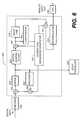
- a communications systemthat may use a PAM data transmission scheme in FIG. 2, reference is now directed to FIG. 3, which further illustrates the general structure of a HDSL transceiver.
- a HDSL transceiver 200may be disposed within a HDSL line card 45 of FIG. 2 at either station in a two-station communication system.
- the HDSL line cardmay be described as a HTU-C 47 .
- a HTU-C 47may comprise an encoder 202 , a digital shaping filter 204 , a digital to analog converter (DAC) 206 , an analog shaping filter 208 , and a hybrid circuit 210 in the upstream data path.
- DACdigital to analog converter
- a HTU-C 47may comprise a hybrid circuit 210 , an analog receive filter 212 , an automatic gain control amplifier (AGC) 214 , a timing recovery circuit 216 , an analog to digital converter (ADC) 218 , an echo canceller 222 , a decision feedback equalizer 224 , a decision device 226 , and a decoder 228 in the downstream data path.
- ADCautomatic gain control amplifier
- ADCanalog to digital converter
- the upstream data transmission portion of a HTU-C 47may function as follows.
- the bits of the digital data input signalmay be encoded into a complex data symbol in encoder 202 .
- the complex data symbolsmay be forwarded to a digital shaping filter 204 and an echo canceller 222 .
- Digital shaping filter 204may take the form of a finite impulse response (FIR) filter selected and used to shape the frequency spectrum across a particular HDSL communication channel.
- the output of the digital shaping filter 204may then be forwarded to DAC 206 .
- the analog representation of the digital data input streammay be further processed by an analog shaping filter 208 .
- analog shaping filter 208may take the form of a Butterworth lowpass filter to control out-of-band energy present in the analog signal.
- the filtered transmit signalmay then be coupled to the twisted pair telephone line via hybrid circuit 210 .
- Hybrid circuit 210may comprise two unidirectional ports (one for data transmission and one for data reception) and one bi-directional port.
- the bi-directional portmay be integrated with the twisted-pair telephone line. If the impedance of the twisted-pair matches the design impedance of the hybrid, there will be perfect isolation between the transmitting and receiving ports within hybrid circuit 210 . For this ideal case, the hybrid circuit 210 return loss is infinity. In reality, the line impedance is a variable of frequency and varies significantly between individual CSA loops.
- a Butterworth low-pass filtermay also be used for the analog receive filter 212 .
- the function of the analog receive filter 212like its counterpart in the transmission path of HTU-C 47 is to reduce out-of-band noise. Having removed the low-frequency out-of-band noise in the analog receive filter 212 , the filtered analog data stream may be forwarded to the AGC 214 .
- AGC 214may be necessary to bring the received signal magnitude to that close to the normal transmit signal level for subsequent digital conversion and processing.
- the filtered and amplified receive signalmay be processed through a timing recovery circuit 216 .
- Timing recovery circuit 216typically coordinates the sampling clocks used to process data in both DAC 206 in the upstream data path, as well as, ADC 218 in the receive data path.
- ADC 218may be synchronized to the DAC 206 through the timing recovery circuit 216 such that upstream and downstream data symbols are synchronized within the HTU-C 47 .
- digital signal processing of the complex data symbols encoded within the received signal pathmay be processed.
- the output of the echo canceller 222 from the upstream data pathmay be mathematically combined with the received signal. The combination may take place in summer 220 .
- Echo canceller 222may be designed to resemble the equivalence of the echo path as defined by both the digital and analog shaping filters 204 , 208 , the DAC 206 , the hybrid circuit 210 , the analog receive filter 212 , the AGC 214 , the timing recovery circuit 216 , and the ADC 218 .
- Possible phase jitter between the transmit signal and the received signalmay be reduced by bit stuffing as defined by the HDSL frame structure.
- the echo path transfer functionis identified with an adaptive signal processing algorithm.
- the digitized and echo-canceled received signalmay be further filtered by decision feedback equalizer 224 before being forwarded to a decision device 226 .
- the decision feedback equalizer 224may comprise a feed-forward filter and a feedback filter.
- the feed-forward filterequalizes the precursor of the CSA loop channel impulse response, while the feedback filter cancels the effect of the post-cursor of the channel impulse response.
- the decision feedback equalizeris necessary for the HTU-C 47 to maintain minimal noise enhancement during the channel equalization process.
- Decision device 226may take the form of a threshold detector configured to correspond to the discrete voltage levels used by the line code. After signal processing in the decision device 226 , received symbols are converted back into signal bits in decoder 228 to create a digital data bit stream.
- FIG. 4is a functional block diagram illustrating an active PAR reducer implemented with a prediction filter.
- the PAR reducer 250may be disposed within HTU-C transceiver 200 between the encoder 202 and the DAC 206 in the upstream or transmit data path.
- the PAR reducer 250may comprise a plurality of summers 252 , a mod2L 254 , a prediction filter 258 , a comparator 260 , a residual filter 262 , an interpolator 264 , and a precoder 266 .
- the PAR reducer 250 illustrated in FIG. 4is particularly suited for operation in multi-carrier transmitters that use Tomlinson precoding.
- Tomlinson precedingprovides a method for minimizing errors propagated in receivers that use a decision feedback equalizer 224 .
- the feedback filter in the decision feedback equalizer 224(see FIG. 3) is moved into the upstream (transmit) data path to filter the original encoded data symbols.
- a modulo operationis used in the feedback loop to make the filtering operation stable. Without the modulo operation in the feedback loop, the feedback filter within the feedback equalizer would behave like a recursive filter which might become unstable given some value of transmit filter coefficients.
- modulo correction of +/ ⁇ 2Lhas the effect of limiting the output signal to the magnitude range of the original input data signal after processing by the feedback filter.
- the choice of the correction stepsmay be seen as an optimization problem that could theoretically be solved by linear programming techniques. These ideal techniques are not suitable to real time solutions, so less complex solutions are necessary.
- the Tomlinson preceding methodmay be implemented in the PAR reducer 250 of FIG.4 in the signal loop created by a first summer 252 disposed between the encoder 202 and the mod2L 254 ; the mod21 254 ; a second summer 252 disposed after the mod2L 254 and prior to prediction filter 258 ; and a precoder 266 .
- the feedback loopis completed by coupling the output of precoder 266 to the first summer 252 .
- the active filter portion of the PAR reducer 250may comprise the prediction filter 258 , a residual filter 262 , an interpolator 264 , and a comparator 260 .
- the complete digital shaping filter 204may be segmented and the causal portion of the digital shaping filter 204 may be used as a prediction filter 258 . If the output of the prediction filter 258 exceeds a given threshold as determined by the comparator 260 , the current data symbol can be corrected before any other action is taken, e.g. before being used by precoder 266 and echo canceller 222 . It is significant to note that the digital shaping filter is segmented, so that operations performed for the prediction are not lost during normal operation. Here, causal means that part of the filter right of the maximum amplitude coefficient.
- that portion of the digital shaping filter 204may be implemented as a residual filter 262 in the upstream data path.
- an interpolator 264may be added after digital shaping to insert symbols not derived from actual data points in the input bit stream to increase the sampling rate of the digital data stream that may be applied to the DAC 206 .
- FIG. 5introduces a functional block diagram illustrating the implementation of a two-stage PAR reducer 275 .
- a two-stage PAR reducer 275may comprise a first-stage comprising a Tomlinson precoder signal processing loop, a digital shaping filter 204 , and a comparator 260 .
- the second stage of the two-stage PAR reducer 275may comprise a Tomlinson precoder signal processing loop, a digital shaping filter 204 , and an interpolator 264 .
- the two stages of the PAR reducer 275may be coupled by a delay line 278 .
- the digital shaping filter 204 in totalis implemented as a prediction filter. For those data symbols present in the digitally shaped output signal that exceed a predetermined threshold in comparator 260 , a correction is applied to the input of the two-stage PAR reducer 275 .
- the original datamust be sampled and delayed by delay line 278 (configured to track the impulse delay of the digital shaping filter 204 and the processing delay in the comparator 260 ) to permit proper insertion of corrected data symbols within the digital data stream. It is important to note that because of the duplicative nature of the functional elements as illustrated in the two-stage PAR reducer 275 of FIG.
- N-pass approachmay be easily derived from the multi-stage approaches illustrated in FIG. 4 and FIG. 5 . Such a N-pass approach may be derived by one skilled in the art and is consistent with the concepts of the PAR reducer of the present invention.
- This third embodiment of a PAR reducermay be designed to take advantage of the nearly linear duo-modulo operation performed in the Tomlinson precoder.
- the full hindsight PAR reducer 300may comprise a Tomlinson precoder signal processing loop, a digital shaping filter 204 , a plurality of summers 252 , a delay line 278 , a comparator 260 , a correction sequences generator 302 , and an interpolator 264 .
- a Tomlinson precoder signal processing loopmay comprise a first summer 252 disposed between the encoder 202 and the input to mod2L 254 ; the mod2L 254 ; a precoder 266 disposed after the mod2L 254 and prior to a second summer 252 .
- the second summer 252may be disposed at the output of the precoder 266 and a precoder correction output signal generated by the correction sequences generator 302 .
- the feedback loopmay be completed by coupling the output of the second summer 252 to an input of the first summer 252 as illustrated.
- the linear approximation PAR reducer 300may be implemented as follows. A digital data stream of Tomlinson precoded data symbols may be injected at the input to the digital shaping filter 204 . The resulting data stream at the output of the digital shaping filter 204 may be sorted in absolute value. Data symbols that exceed a predetermined threshold applied in comparator 260 may be identified and corrected in the correction sequences generator 302 .
- the correction sequences generator 302may be configured to provide correction sequences corresponding to the negated impulse responses of the uncorrected system if a 2L impulse was injected after mod2L 254 .
- a precoder correction sequencemay be forwarded as a feedback signal to the second summer 252 coupled to the output of the precoder 266 .
- a causal correction sequencemay be forwarded as a feedback signal coupled to the third summer 252 further coupled at the output of the digital shaping filter 204 .
- a third non-delayed correction sequencemay be forwarded by the correction sequences generator 302 to the input at a fourth summer 252 , the fourth summer further coupled to the output of the delay line 278 .
- the three correction sequencesmay be configured after application of each of the impulse corrections as injection of a correction sequence is the equivalent of providing the impulse response corresponding to the correction sequence in the three locations where correction is applied.
- the correction sequencesare predictable and may be implemented by storing them in read only memory (ROM).
- an optional interpolator 264may be added after digital modulation processing to insert symbols not derived from actual data points in the input signal bit stream to increase the sampling rate of the encoded signals that may be applied to the DAC 206 .
- the modulation schemeis not completely linear.
- the duo-modulo operationis non-linear, but a good approximation, as it is piecewise linear.
- the PAR reducer 300is an approximation of the previously introduced embodiments.
Landscapes
- Engineering & Computer Science (AREA)
- Computer Networks & Wireless Communication (AREA)
- Signal Processing (AREA)
- Power Engineering (AREA)
- Cable Transmission Systems, Equalization Of Radio And Reduction Of Echo (AREA)
Abstract
Description


Claims (29)
Priority Applications (1)
| Application Number | Priority Date | Filing Date | Title |
|---|---|---|---|
| US09/505,528US6597746B1 (en) | 1999-02-18 | 2000-02-17 | System and method for peak to average power ratio reduction |
Applications Claiming Priority (2)
| Application Number | Priority Date | Filing Date | Title |
|---|---|---|---|
| US12049499P | 1999-02-18 | 1999-02-18 | |
| US09/505,528US6597746B1 (en) | 1999-02-18 | 2000-02-17 | System and method for peak to average power ratio reduction |
Publications (1)
| Publication Number | Publication Date |
|---|---|
| US6597746B1true US6597746B1 (en) | 2003-07-22 |
Family
ID=26818427
Family Applications (1)
| Application Number | Title | Priority Date | Filing Date |
|---|---|---|---|
| US09/505,528Expired - Fee RelatedUS6597746B1 (en) | 1999-02-18 | 2000-02-17 | System and method for peak to average power ratio reduction |
Country Status (1)
| Country | Link |
|---|---|
| US (1) | US6597746B1 (en) |
Cited By (66)
| Publication number | Priority date | Publication date | Assignee | Title |
|---|---|---|---|---|
| US20020181576A1 (en)* | 2001-06-05 | 2002-12-05 | Kennedy Rodney A. | Blind magnitude equalizer for segment sync-based timing recovery of receivers |
| US20020196839A1 (en)* | 2000-04-19 | 2002-12-26 | Hunton Matthew J. | Method for peak power reduction in spread spectrum communications systems |
| US20030043895A1 (en)* | 2001-08-28 | 2003-03-06 | Melsa Peter J. | Oversampled clip-shaping |
| US20030064737A1 (en)* | 2001-09-28 | 2003-04-03 | Patrik Eriksson | Method and apparatus for distortionless peak reduction |
| US20030063680A1 (en)* | 2001-09-28 | 2003-04-03 | Nec Usa, Inc. | Per-bin DFE for advanced OQAM-based multi-carrier wireless data transmission systems |
| US20030067990A1 (en)* | 2001-10-01 | 2003-04-10 | Bryant Paul Henry | Peak to average power ratio reduction in a digitally-modulated signal |
| US20030165159A1 (en)* | 2002-01-15 | 2003-09-04 | Dietmar Straussnigg | Method for compensating for peak values during a data transmission with discrete multitone symbols and a circuit arrangement for carrying out the method |
| US20040096022A1 (en)* | 2002-11-20 | 2004-05-20 | Conexant Systems, Inc. | Combining precoding with spectral shaping |
| US20040101062A1 (en)* | 2002-11-27 | 2004-05-27 | Lindh Lars E. | Transmission of signal |
| US20040120414A1 (en)* | 2002-09-30 | 2004-06-24 | Gerald Harron | Method and apparatus for reducing peak to average power ratio in QAM multi-channel blocks |
| US20040131129A1 (en)* | 2002-09-30 | 2004-07-08 | Gerald Harron | Method and apparatus for reducing the power consumption of the power amplifier used in a QAM modulator |
| US20040150655A1 (en)* | 2002-07-01 | 2004-08-05 | Stmicroelectronics S.R.L. | Method and device for processing video signals for presentation on a display and corresponding computer program product |
| US20050089116A1 (en)* | 2003-10-23 | 2005-04-28 | Moffatt Christopher D. | System and method for reducing peak-to-average power ratio for multi-carrier communication systems |
| US20050141410A1 (en)* | 2003-10-30 | 2005-06-30 | 1021 Technologies Inc. | Method of reducing peak-to-average ratio in multi-carrier communications systems |
| US6931079B1 (en)* | 2000-06-21 | 2005-08-16 | Broadcom Corporation | Power reduction |
| US20060014500A1 (en)* | 2004-07-06 | 2006-01-19 | Stefano Marsili | Devices for reducing the dynamic range of signals in transmitters of communication systems |
| US7068780B1 (en)* | 2000-08-30 | 2006-06-27 | Conexant, Inc. | Hybrid echo canceller |
| US7139322B1 (en)* | 2002-07-15 | 2006-11-21 | National Semiconductor Corporation | Method for reducing peak-to-average power ratios in a multi-carrier transmission system |
| US20070041428A1 (en)* | 2005-08-22 | 2007-02-22 | Nec Laboratories America, Inc. | Nonlinear precoding in code-division multiple access communication system |
| US20080063099A1 (en)* | 2000-09-13 | 2008-03-13 | Qualcomm Incorporated | Signaling method in an ofdm multiple access system |
| WO2007102896A3 (en)* | 2005-11-18 | 2008-04-10 | Qualcomm Inc | Frequency division multiple access schemes for wireless communication |
| WO2007127369A3 (en)* | 2006-04-26 | 2008-08-07 | Quellan Inc | Method and system for reducing radiated emissions from a communications channel |
| US20080317109A1 (en)* | 2007-06-19 | 2008-12-25 | Agere Systems Inc. | Characterizing non-compensable jitter in an electronic signal |
| US20090078757A1 (en)* | 2006-03-24 | 2009-03-26 | Hanson Bradley C | Information management system and method |
| US8045512B2 (en) | 2005-10-27 | 2011-10-25 | Qualcomm Incorporated | Scalable frequency band operation in wireless communication systems |
| CN102255700A (en)* | 2011-08-22 | 2011-11-23 | 宁波大学 | Anti-noise wireless signal framing modulation method of multimedia broadcasting single frequency network |
| CN102281246A (en)* | 2011-08-22 | 2011-12-14 | 宁波大学 | Anti-fading method for transmitting wireless digital broadcast signal in single frequency network |
| CN102281236A (en)* | 2011-08-22 | 2011-12-14 | 宁波大学 | Anti-noise mobile multimedia broadcast signal framing modulation method |
| CN102299889A (en)* | 2011-08-22 | 2011-12-28 | 宁波大学 | Multimedia broadcasting single frequency network signal framing modulation method |
| CN102307172A (en)* | 2011-08-22 | 2012-01-04 | 宁波大学 | Framing and modulating method for robustness wireless multimedia broadcast signal with single frequency network |
| CN102394852A (en)* | 2011-08-22 | 2012-03-28 | 宁波大学 | Single-frequency network anti-fading wireless multimedia broadcasting signal framing modulation method |
| CN102394853A (en)* | 2011-08-22 | 2012-03-28 | 宁波大学 | Multimedia broadcasting single-frequency network robust wireless signal framing modulation method |
| US8279783B1 (en)* | 2005-08-12 | 2012-10-02 | Aquantia Corporation | Linear-equivalent echo and next cancellers for Tomlinson-Harashima Precoding (THP) systems |
| US8446892B2 (en) | 2005-03-16 | 2013-05-21 | Qualcomm Incorporated | Channel structures for a quasi-orthogonal multiple-access communication system |
| US8462859B2 (en) | 2005-06-01 | 2013-06-11 | Qualcomm Incorporated | Sphere decoding apparatus |
| US8477684B2 (en) | 2005-10-27 | 2013-07-02 | Qualcomm Incorporated | Acknowledgement of control messages in a wireless communication system |
| US8565194B2 (en) | 2005-10-27 | 2013-10-22 | Qualcomm Incorporated | Puncturing signaling channel for a wireless communication system |
| US8582509B2 (en) | 2005-10-27 | 2013-11-12 | Qualcomm Incorporated | Scalable frequency band operation in wireless communication systems |
| US8599945B2 (en) | 2005-06-16 | 2013-12-03 | Qualcomm Incorporated | Robust rank prediction for a MIMO system |
| US8611284B2 (en) | 2005-05-31 | 2013-12-17 | Qualcomm Incorporated | Use of supplemental assignments to decrement resources |
| US8644292B2 (en) | 2005-08-24 | 2014-02-04 | Qualcomm Incorporated | Varied transmission time intervals for wireless communication system |
| US8693405B2 (en) | 2005-10-27 | 2014-04-08 | Qualcomm Incorporated | SDMA resource management |
| US8879511B2 (en) | 2005-10-27 | 2014-11-04 | Qualcomm Incorporated | Assignment acknowledgement for a wireless communication system |
| US8885628B2 (en) | 2005-08-08 | 2014-11-11 | Qualcomm Incorporated | Code division multiplexing in a single-carrier frequency division multiple access system |
| US8917654B2 (en) | 2005-04-19 | 2014-12-23 | Qualcomm Incorporated | Frequency hopping design for single carrier FDMA systems |
| US9088384B2 (en) | 2005-10-27 | 2015-07-21 | Qualcomm Incorporated | Pilot symbol transmission in wireless communication systems |
| US9130810B2 (en) | 2000-09-13 | 2015-09-08 | Qualcomm Incorporated | OFDM communications methods and apparatus |
| US9136974B2 (en) | 2005-08-30 | 2015-09-15 | Qualcomm Incorporated | Precoding and SDMA support |
| US9137822B2 (en) | 2004-07-21 | 2015-09-15 | Qualcomm Incorporated | Efficient signaling over access channel |
| US9143305B2 (en) | 2005-03-17 | 2015-09-22 | Qualcomm Incorporated | Pilot signal transmission for an orthogonal frequency division wireless communication system |
| US9144060B2 (en) | 2005-10-27 | 2015-09-22 | Qualcomm Incorporated | Resource allocation for shared signaling channels |
| US9148256B2 (en) | 2004-07-21 | 2015-09-29 | Qualcomm Incorporated | Performance based rank prediction for MIMO design |
| US9154211B2 (en) | 2005-03-11 | 2015-10-06 | Qualcomm Incorporated | Systems and methods for beamforming feedback in multi antenna communication systems |
| US9160579B1 (en)* | 2014-03-26 | 2015-10-13 | Nokia Solutions And Networks Oy | Low PAPR modulation for coverage enhancement |
| US9172453B2 (en) | 2005-10-27 | 2015-10-27 | Qualcomm Incorporated | Method and apparatus for pre-coding frequency division duplexing system |
| US9179319B2 (en) | 2005-06-16 | 2015-11-03 | Qualcomm Incorporated | Adaptive sectorization in cellular systems |
| US9184870B2 (en) | 2005-04-01 | 2015-11-10 | Qualcomm Incorporated | Systems and methods for control channel signaling |
| US9209956B2 (en) | 2005-08-22 | 2015-12-08 | Qualcomm Incorporated | Segment sensitive scheduling |
| US9210651B2 (en) | 2005-10-27 | 2015-12-08 | Qualcomm Incorporated | Method and apparatus for bootstraping information in a communication system |
| US9225416B2 (en) | 2005-10-27 | 2015-12-29 | Qualcomm Incorporated | Varied signaling channels for a reverse link in a wireless communication system |
| US9225488B2 (en) | 2005-10-27 | 2015-12-29 | Qualcomm Incorporated | Shared signaling channel |
| US9246560B2 (en) | 2005-03-10 | 2016-01-26 | Qualcomm Incorporated | Systems and methods for beamforming and rate control in a multi-input multi-output communication systems |
| US9307544B2 (en) | 2005-04-19 | 2016-04-05 | Qualcomm Incorporated | Channel quality reporting for adaptive sectorization |
| US9461859B2 (en) | 2005-03-17 | 2016-10-04 | Qualcomm Incorporated | Pilot signal transmission for an orthogonal frequency division wireless communication system |
| US9520972B2 (en) | 2005-03-17 | 2016-12-13 | Qualcomm Incorporated | Pilot signal transmission for an orthogonal frequency division wireless communication system |
| US9660776B2 (en) | 2005-08-22 | 2017-05-23 | Qualcomm Incorporated | Method and apparatus for providing antenna diversity in a wireless communication system |
Citations (2)
| Publication number | Priority date | Publication date | Assignee | Title |
|---|---|---|---|---|
| US4651231A (en)* | 1984-09-13 | 1987-03-17 | Reference Technology, Inc. | Timing system for laser disc having digital information |
| US6081820A (en)* | 1998-02-20 | 2000-06-27 | Siemens Energy & Automation | Method and apparatus for filtering a signal using a window value |
- 2000
- 2000-02-17USUS09/505,528patent/US6597746B1/ennot_activeExpired - Fee Related
Patent Citations (2)
| Publication number | Priority date | Publication date | Assignee | Title |
|---|---|---|---|---|
| US4651231A (en)* | 1984-09-13 | 1987-03-17 | Reference Technology, Inc. | Timing system for laser disc having digital information |
| US6081820A (en)* | 1998-02-20 | 2000-06-27 | Siemens Energy & Automation | Method and apparatus for filtering a signal using a window value |
Cited By (127)
| Publication number | Priority date | Publication date | Assignee | Title |
|---|---|---|---|---|
| US7003017B2 (en)* | 2000-04-19 | 2006-02-21 | Powerwave Technologies, Inc. | Method for peak power reduction in spread spectrum communications systems |
| US20020196839A1 (en)* | 2000-04-19 | 2002-12-26 | Hunton Matthew J. | Method for peak power reduction in spread spectrum communications systems |
| US7187722B2 (en) | 2000-06-21 | 2007-03-06 | Broadcom Corporation | Power reduction |
| US20050232373A1 (en)* | 2000-06-21 | 2005-10-20 | Broadcom Corporation | Power reduction |
| US6931079B1 (en)* | 2000-06-21 | 2005-08-16 | Broadcom Corporation | Power reduction |
| US7068780B1 (en)* | 2000-08-30 | 2006-06-27 | Conexant, Inc. | Hybrid echo canceller |
| US8098569B2 (en) | 2000-09-13 | 2012-01-17 | Qualcomm Incorporated | Signaling method in an OFDM multiple access system |
| US10313069B2 (en) | 2000-09-13 | 2019-06-04 | Qualcomm Incorporated | Signaling method in an OFDM multiple access system |
| US7990843B2 (en) | 2000-09-13 | 2011-08-02 | Qualcomm Incorporated | Signaling method in an OFDM multiple access system |
| US7990844B2 (en) | 2000-09-13 | 2011-08-02 | Qualcomm Incorporated | Signaling method in an OFDM multiple access system |
| US8223627B2 (en) | 2000-09-13 | 2012-07-17 | Qualcomm Incorporated | Signaling method in an OFDM multiple access system |
| US7916624B2 (en) | 2000-09-13 | 2011-03-29 | Qualcomm Incorporated | Signaling method in an OFDM multiple access system |
| US8098568B2 (en) | 2000-09-13 | 2012-01-17 | Qualcomm Incorporated | Signaling method in an OFDM multiple access system |
| US20080063099A1 (en)* | 2000-09-13 | 2008-03-13 | Qualcomm Incorporated | Signaling method in an ofdm multiple access system |
| US8199634B2 (en) | 2000-09-13 | 2012-06-12 | Qualcomm Incorporated | Signaling method in an OFDM multiple access system |
| US7924699B2 (en) | 2000-09-13 | 2011-04-12 | Qualcomm Incorporated | Signaling method in an OFDM multiple access system |
| US9130810B2 (en) | 2000-09-13 | 2015-09-08 | Qualcomm Incorporated | OFDM communications methods and apparatus |
| US7623442B2 (en) | 2000-09-13 | 2009-11-24 | Qualcomm Incorporated | Signaling method in an OFDM multiple access system |
| US8014271B2 (en) | 2000-09-13 | 2011-09-06 | Qualcomm Incorporated | Signaling method in an OFDM multiple access system |
| US8218425B2 (en) | 2000-09-13 | 2012-07-10 | Qualcomm Incorporated | Signaling method in an OFDM multiple access system |
| US9426012B2 (en) | 2000-09-13 | 2016-08-23 | Qualcomm Incorporated | Signaling method in an OFDM multiple access system |
| US20090201795A1 (en)* | 2000-09-13 | 2009-08-13 | Qualcomm Incorporated | Signaling method in an ofdm multiple access system |
| US8295154B2 (en) | 2000-09-13 | 2012-10-23 | Qualcomm Incorporated | Signaling method in an OFDM multiple access system |
| US11032035B2 (en) | 2000-09-13 | 2021-06-08 | Qualcomm Incorporated | Signaling method in an OFDM multiple access system |
| US20020181576A1 (en)* | 2001-06-05 | 2002-12-05 | Kennedy Rodney A. | Blind magnitude equalizer for segment sync-based timing recovery of receivers |
| US7269216B2 (en)* | 2001-06-05 | 2007-09-11 | Kennedy Rodney A | Blind magnitude equalizer for segment sync-based timing recovery of receivers |
| US7110445B2 (en)* | 2001-08-28 | 2006-09-19 | Texas Instruments Incorporated | Oversampled clip-shaping |
| US20030043895A1 (en)* | 2001-08-28 | 2003-03-06 | Melsa Peter J. | Oversampled clip-shaping |
| US20030064737A1 (en)* | 2001-09-28 | 2003-04-03 | Patrik Eriksson | Method and apparatus for distortionless peak reduction |
| US20030063680A1 (en)* | 2001-09-28 | 2003-04-03 | Nec Usa, Inc. | Per-bin DFE for advanced OQAM-based multi-carrier wireless data transmission systems |
| US7436881B2 (en)* | 2001-09-28 | 2008-10-14 | Nec Corporation | Per-bin DFE for advanced OQAM-based multi-carrier wireless data transmission systems |
| US20030067990A1 (en)* | 2001-10-01 | 2003-04-10 | Bryant Paul Henry | Peak to average power ratio reduction in a digitally-modulated signal |
| US20030165159A1 (en)* | 2002-01-15 | 2003-09-04 | Dietmar Straussnigg | Method for compensating for peak values during a data transmission with discrete multitone symbols and a circuit arrangement for carrying out the method |
| US7359443B2 (en)* | 2002-01-15 | 2008-04-15 | Infineon Technologies Ag | Method for compensating for peak values during a data transmission with discrete multitone symbols and a circuit arrangement for carrying out the method |
| US20040150655A1 (en)* | 2002-07-01 | 2004-08-05 | Stmicroelectronics S.R.L. | Method and device for processing video signals for presentation on a display and corresponding computer program product |
| US7012618B2 (en)* | 2002-07-01 | 2006-03-14 | Stmicroelectronics S.R.L. | Method and device for processing video signals for presentation on a display and corresponding computer program product |
| US7139322B1 (en)* | 2002-07-15 | 2006-11-21 | National Semiconductor Corporation | Method for reducing peak-to-average power ratios in a multi-carrier transmission system |
| US7675986B1 (en) | 2002-07-15 | 2010-03-09 | National Semiconductor Corporation | Method for reducing peak-to-average power ratios in a multi-carrier transmission system |
| US20040131129A1 (en)* | 2002-09-30 | 2004-07-08 | Gerald Harron | Method and apparatus for reducing the power consumption of the power amplifier used in a QAM modulator |
| US20040120414A1 (en)* | 2002-09-30 | 2004-06-24 | Gerald Harron | Method and apparatus for reducing peak to average power ratio in QAM multi-channel blocks |
| US7212582B2 (en)* | 2002-11-20 | 2007-05-01 | Mindspeed Technologies, Inc. | Combining precoding with spectral shaping |
| US20040096022A1 (en)* | 2002-11-20 | 2004-05-20 | Conexant Systems, Inc. | Combining precoding with spectral shaping |
| US7212583B2 (en)* | 2002-11-27 | 2007-05-01 | Nokia Corporation | Transmission of signal |
| US20040101062A1 (en)* | 2002-11-27 | 2004-05-27 | Lindh Lars E. | Transmission of signal |
| WO2005043853A1 (en)* | 2003-10-23 | 2005-05-12 | Harris Corporation | System and method for reducing peak-to-average power ratio for multi-carrier communication systems |
| US7822136B2 (en) | 2003-10-23 | 2010-10-26 | Harris Corporation | System and method for reducing peak-to-average power ratio for multi-carrier communication systems |
| US20100020897A1 (en)* | 2003-10-23 | 2010-01-28 | Christopher Douglas Moffatt | System and method for reducing peak-to-average power ratio for multi-carrier communication systems |
| US7639747B2 (en) | 2003-10-23 | 2009-12-29 | Harris Corporation | System and method for reducing peak-to-average power ratio for multi-carrier communication systems |
| US8442137B2 (en) | 2003-10-23 | 2013-05-14 | Harris Corporation | System and method for reducing peak-to-average power ratio for multi-carrier communication systems |
| US20050089116A1 (en)* | 2003-10-23 | 2005-04-28 | Moffatt Christopher D. | System and method for reducing peak-to-average power ratio for multi-carrier communication systems |
| US20050141410A1 (en)* | 2003-10-30 | 2005-06-30 | 1021 Technologies Inc. | Method of reducing peak-to-average ratio in multi-carrier communications systems |
| DE102004032667B4 (en)* | 2004-07-06 | 2009-12-03 | Infineon Technologies Ag | Device for reducing the dynamic range of signals in transmitters of communication systems |
| US7340224B2 (en) | 2004-07-06 | 2008-03-04 | Infineon Technologies Ag | Devices for reducing the dynamic range of signals in transmitters of communication systems |
| US20060014500A1 (en)* | 2004-07-06 | 2006-01-19 | Stefano Marsili | Devices for reducing the dynamic range of signals in transmitters of communication systems |
| US9137822B2 (en) | 2004-07-21 | 2015-09-15 | Qualcomm Incorporated | Efficient signaling over access channel |
| US11039468B2 (en) | 2004-07-21 | 2021-06-15 | Qualcomm Incorporated | Efficient signaling over access channel |
| US10849156B2 (en) | 2004-07-21 | 2020-11-24 | Qualcomm Incorporated | Efficient signaling over access channel |
| US10517114B2 (en) | 2004-07-21 | 2019-12-24 | Qualcomm Incorporated | Efficient signaling over access channel |
| US10237892B2 (en) | 2004-07-21 | 2019-03-19 | Qualcomm Incorporated | Efficient signaling over access channel |
| US10194463B2 (en) | 2004-07-21 | 2019-01-29 | Qualcomm Incorporated | Efficient signaling over access channel |
| US9148256B2 (en) | 2004-07-21 | 2015-09-29 | Qualcomm Incorporated | Performance based rank prediction for MIMO design |
| US9246560B2 (en) | 2005-03-10 | 2016-01-26 | Qualcomm Incorporated | Systems and methods for beamforming and rate control in a multi-input multi-output communication systems |
| US9154211B2 (en) | 2005-03-11 | 2015-10-06 | Qualcomm Incorporated | Systems and methods for beamforming feedback in multi antenna communication systems |
| US8446892B2 (en) | 2005-03-16 | 2013-05-21 | Qualcomm Incorporated | Channel structures for a quasi-orthogonal multiple-access communication system |
| US8547951B2 (en) | 2005-03-16 | 2013-10-01 | Qualcomm Incorporated | Channel structures for a quasi-orthogonal multiple-access communication system |
| US9461859B2 (en) | 2005-03-17 | 2016-10-04 | Qualcomm Incorporated | Pilot signal transmission for an orthogonal frequency division wireless communication system |
| US9520972B2 (en) | 2005-03-17 | 2016-12-13 | Qualcomm Incorporated | Pilot signal transmission for an orthogonal frequency division wireless communication system |
| US9143305B2 (en) | 2005-03-17 | 2015-09-22 | Qualcomm Incorporated | Pilot signal transmission for an orthogonal frequency division wireless communication system |
| US9184870B2 (en) | 2005-04-01 | 2015-11-10 | Qualcomm Incorporated | Systems and methods for control channel signaling |
| US9036538B2 (en) | 2005-04-19 | 2015-05-19 | Qualcomm Incorporated | Frequency hopping design for single carrier FDMA systems |
| US9408220B2 (en) | 2005-04-19 | 2016-08-02 | Qualcomm Incorporated | Channel quality reporting for adaptive sectorization |
| US9307544B2 (en) | 2005-04-19 | 2016-04-05 | Qualcomm Incorporated | Channel quality reporting for adaptive sectorization |
| US8917654B2 (en) | 2005-04-19 | 2014-12-23 | Qualcomm Incorporated | Frequency hopping design for single carrier FDMA systems |
| US8611284B2 (en) | 2005-05-31 | 2013-12-17 | Qualcomm Incorporated | Use of supplemental assignments to decrement resources |
| US8462859B2 (en) | 2005-06-01 | 2013-06-11 | Qualcomm Incorporated | Sphere decoding apparatus |
| US9179319B2 (en) | 2005-06-16 | 2015-11-03 | Qualcomm Incorporated | Adaptive sectorization in cellular systems |
| US8599945B2 (en) | 2005-06-16 | 2013-12-03 | Qualcomm Incorporated | Robust rank prediction for a MIMO system |
| US8885628B2 (en) | 2005-08-08 | 2014-11-11 | Qualcomm Incorporated | Code division multiplexing in a single-carrier frequency division multiple access system |
| US9693339B2 (en) | 2005-08-08 | 2017-06-27 | Qualcomm Incorporated | Code division multiplexing in a single-carrier frequency division multiple access system |
| US8279783B1 (en)* | 2005-08-12 | 2012-10-02 | Aquantia Corporation | Linear-equivalent echo and next cancellers for Tomlinson-Harashima Precoding (THP) systems |
| US9209956B2 (en) | 2005-08-22 | 2015-12-08 | Qualcomm Incorporated | Segment sensitive scheduling |
| US9246659B2 (en) | 2005-08-22 | 2016-01-26 | Qualcomm Incorporated | Segment sensitive scheduling |
| US9660776B2 (en) | 2005-08-22 | 2017-05-23 | Qualcomm Incorporated | Method and apparatus for providing antenna diversity in a wireless communication system |
| US7580445B2 (en)* | 2005-08-22 | 2009-08-25 | Nec Laboratories America, Inc. | Nonlinear precoding in code-division multiple access communication system |
| US9240877B2 (en) | 2005-08-22 | 2016-01-19 | Qualcomm Incorporated | Segment sensitive scheduling |
| US20070041428A1 (en)* | 2005-08-22 | 2007-02-22 | Nec Laboratories America, Inc. | Nonlinear precoding in code-division multiple access communication system |
| US9860033B2 (en) | 2005-08-22 | 2018-01-02 | Qualcomm Incorporated | Method and apparatus for antenna diversity in multi-input multi-output communication systems |
| US8644292B2 (en) | 2005-08-24 | 2014-02-04 | Qualcomm Incorporated | Varied transmission time intervals for wireless communication system |
| US8787347B2 (en) | 2005-08-24 | 2014-07-22 | Qualcomm Incorporated | Varied transmission time intervals for wireless communication system |
| US9136974B2 (en) | 2005-08-30 | 2015-09-15 | Qualcomm Incorporated | Precoding and SDMA support |
| US9088384B2 (en) | 2005-10-27 | 2015-07-21 | Qualcomm Incorporated | Pilot symbol transmission in wireless communication systems |
| US8582509B2 (en) | 2005-10-27 | 2013-11-12 | Qualcomm Incorporated | Scalable frequency band operation in wireless communication systems |
| US8477684B2 (en) | 2005-10-27 | 2013-07-02 | Qualcomm Incorporated | Acknowledgement of control messages in a wireless communication system |
| US8879511B2 (en) | 2005-10-27 | 2014-11-04 | Qualcomm Incorporated | Assignment acknowledgement for a wireless communication system |
| US8045512B2 (en) | 2005-10-27 | 2011-10-25 | Qualcomm Incorporated | Scalable frequency band operation in wireless communication systems |
| US8842619B2 (en) | 2005-10-27 | 2014-09-23 | Qualcomm Incorporated | Scalable frequency band operation in wireless communication systems |
| US9144060B2 (en) | 2005-10-27 | 2015-09-22 | Qualcomm Incorporated | Resource allocation for shared signaling channels |
| US8693405B2 (en) | 2005-10-27 | 2014-04-08 | Qualcomm Incorporated | SDMA resource management |
| US10805038B2 (en) | 2005-10-27 | 2020-10-13 | Qualcomm Incorporated | Puncturing signaling channel for a wireless communication system |
| US9225488B2 (en) | 2005-10-27 | 2015-12-29 | Qualcomm Incorporated | Shared signaling channel |
| US9172453B2 (en) | 2005-10-27 | 2015-10-27 | Qualcomm Incorporated | Method and apparatus for pre-coding frequency division duplexing system |
| US9225416B2 (en) | 2005-10-27 | 2015-12-29 | Qualcomm Incorporated | Varied signaling channels for a reverse link in a wireless communication system |
| US9210651B2 (en) | 2005-10-27 | 2015-12-08 | Qualcomm Incorporated | Method and apparatus for bootstraping information in a communication system |
| US8565194B2 (en) | 2005-10-27 | 2013-10-22 | Qualcomm Incorporated | Puncturing signaling channel for a wireless communication system |
| US8582548B2 (en) | 2005-11-18 | 2013-11-12 | Qualcomm Incorporated | Frequency division multiple access schemes for wireless communication |
| US8681764B2 (en) | 2005-11-18 | 2014-03-25 | Qualcomm Incorporated | Frequency division multiple access schemes for wireless communication |
| WO2007102896A3 (en)* | 2005-11-18 | 2008-04-10 | Qualcomm Inc | Frequency division multiple access schemes for wireless communication |
| US20090078757A1 (en)* | 2006-03-24 | 2009-03-26 | Hanson Bradley C | Information management system and method |
| WO2007127369A3 (en)* | 2006-04-26 | 2008-08-07 | Quellan Inc | Method and system for reducing radiated emissions from a communications channel |
| US9252983B2 (en)* | 2006-04-26 | 2016-02-02 | Intersil Americas LLC | Method and system for reducing radiated emissions from a communications channel |
| US8085837B2 (en)* | 2007-06-19 | 2011-12-27 | Agere Systems Inc. | Characterizing non-compensable jitter in an electronic signal |
| US20080317109A1 (en)* | 2007-06-19 | 2008-12-25 | Agere Systems Inc. | Characterizing non-compensable jitter in an electronic signal |
| CN102255700B (en)* | 2011-08-22 | 2013-08-21 | 宁波大学 | Anti-noise wireless signal framing modulation method of multimedia broadcasting single frequency network |
| CN102281246A (en)* | 2011-08-22 | 2011-12-14 | 宁波大学 | Anti-fading method for transmitting wireless digital broadcast signal in single frequency network |
| CN102394853B (en)* | 2011-08-22 | 2013-07-24 | 宁波大学 | Multimedia broadcasting single-frequency network robust wireless signal framing modulation method |
| CN102281246B (en)* | 2011-08-22 | 2013-07-24 | 宁波大学 | Anti-fading method for transmitting wireless digital broadcast signal in single frequency network |
| CN102307172B (en)* | 2011-08-22 | 2013-07-24 | 宁波大学 | Framing and modulating method for robustness wireless multimedia broadcast signal with single frequency network |
| CN102307172A (en)* | 2011-08-22 | 2012-01-04 | 宁波大学 | Framing and modulating method for robustness wireless multimedia broadcast signal with single frequency network |
| CN102255700A (en)* | 2011-08-22 | 2011-11-23 | 宁波大学 | Anti-noise wireless signal framing modulation method of multimedia broadcasting single frequency network |
| CN102281236B (en)* | 2011-08-22 | 2013-07-24 | 宁波大学 | Anti-noise mobile multimedia broadcast signal framing modulation method |
| CN102281236A (en)* | 2011-08-22 | 2011-12-14 | 宁波大学 | Anti-noise mobile multimedia broadcast signal framing modulation method |
| CN102394852B (en)* | 2011-08-22 | 2013-08-21 | 宁波大学 | Single-frequency network anti-fading wireless multimedia broadcasting signal framing modulation method |
| CN102394853A (en)* | 2011-08-22 | 2012-03-28 | 宁波大学 | Multimedia broadcasting single-frequency network robust wireless signal framing modulation method |
| CN102299889B (en)* | 2011-08-22 | 2013-08-21 | 宁波大学 | Multimedia broadcasting single frequency network signal framing modulation method |
| CN102394852A (en)* | 2011-08-22 | 2012-03-28 | 宁波大学 | Single-frequency network anti-fading wireless multimedia broadcasting signal framing modulation method |
| CN102299889A (en)* | 2011-08-22 | 2011-12-28 | 宁波大学 | Multimedia broadcasting single frequency network signal framing modulation method |
| US9160579B1 (en)* | 2014-03-26 | 2015-10-13 | Nokia Solutions And Networks Oy | Low PAPR modulation for coverage enhancement |
Similar Documents
| Publication | Publication Date | Title |
|---|---|---|
| US6597746B1 (en) | System and method for peak to average power ratio reduction | |
| Cherubini et al. | Filtered multitone modulation for very high-speed digital subscriber lines | |
| US6353629B1 (en) | Poly-path time domain equalization | |
| US7218681B2 (en) | Method and apparatus for cross-talk mitigation through joint multiuser adaptive pre-coding | |
| US5809033A (en) | Use of modified line encoding and low signal-to-noise ratio based signal processing to extend range of digital data transmission over repeaterless two-wire telephone link | |
| US7076514B2 (en) | Method and system for computing pre-equalizer coefficients | |
| KR100848660B1 (en) | Adaptive equalizer having a variable step size influnenced by output from a trellis decoder | |
| US6266367B1 (en) | Combined echo canceller and time domain equalizer | |
| US7013421B2 (en) | Trellis interleaver and feedback precoder | |
| JP3933971B2 (en) | Method for modulating digital signal and transceiver for transmitting discrete multi-tone modulated signal | |
| US6011814A (en) | Adaptive comb filter and decision feedback equalizer for noise suppression | |
| EP2351240A1 (en) | Method for robust crosstalk precoder training in channels with impulse noise | |
| US6823002B1 (en) | Linear block interleaver for discrete multi-tone modulation | |
| US7561626B2 (en) | Method and system for channel estimation in a data transmission system | |
| JP2001148643A (en) | Equalization processing adaptive for each bin in window control discrete multi-tone type modem receiver | |
| EP1420557B1 (en) | Combined equalization for a DMT receiver | |
| US20100293442A1 (en) | Multi-tap frequency domain equalization with decision feedback and trellis decoding | |
| US6788752B1 (en) | Multi-carrier transmission system | |
| US6741701B1 (en) | Dual echo canceller and method for increasing dynamic range of a receiver | |
| US6668023B1 (en) | Linear block interleaver system and method | |
| US6781965B1 (en) | Method and apparatus for echo cancellation updates in a multicarrier transceiver system | |
| WO2005125132A1 (en) | Training sequence for channel estimation in a data transmission system | |
| US20060133467A1 (en) | Method and apparatus for generating a periodic training signal | |
| EP1303093B1 (en) | Impuse response shortening in DMT modems | |
| US6647076B1 (en) | Method of compensating for interference in a signal generated by discrete multitone modulation, and circuit configuration for carrying out the method. |
Legal Events
| Date | Code | Title | Description |
|---|---|---|---|
| AS | Assignment | Owner name:GLOBESPAN, INC., NEW JERSEY Free format text:ASSIGNMENT OF ASSIGNORS INTEREST;ASSIGNORS:AMRANY, DANIEL;DELVAUX, MARC;GUT, RICHARD;AND OTHERS;REEL/FRAME:011017/0465;SIGNING DATES FROM 20000612 TO 20000707 | |
| AS | Assignment | Owner name:GLOBESPAN VIRATA, INC., NEW JERSEY Free format text:CHANGE OF NAME;ASSIGNOR:GLOBESPAN, INC.;REEL/FRAME:012540/0103 Effective date:20011214 | |
| CC | Certificate of correction | ||
| AS | Assignment | Owner name:CONEXANT, INC.,NEW JERSEY Free format text:CHANGE OF NAME;ASSIGNOR:GLOBESPANVIRATA, INC.;REEL/FRAME:018471/0286 Effective date:20040528 Owner name:CONEXANT, INC., NEW JERSEY Free format text:CHANGE OF NAME;ASSIGNOR:GLOBESPANVIRATA, INC.;REEL/FRAME:018471/0286 Effective date:20040528 | |
| AS | Assignment | Owner name:BANK OF NEW YORK TRUST COMPANY, N.A., THE,ILLINOIS Free format text:SECURITY AGREEMENT;ASSIGNOR:BROOKTREE BROADBAND HOLDING, INC.;REEL/FRAME:018573/0337 Effective date:20061113 Owner name:BANK OF NEW YORK TRUST COMPANY, N.A., THE, ILLINOI Free format text:SECURITY AGREEMENT;ASSIGNOR:BROOKTREE BROADBAND HOLDING, INC.;REEL/FRAME:018573/0337 Effective date:20061113 | |
| FPAY | Fee payment | Year of fee payment:4 | |
| AS | Assignment | Owner name:BROOKTREE BROADBAND HOLDING, INC.,CALIFORNIA Free format text:ASSIGNMENT OF ASSIGNORS INTEREST;ASSIGNOR:GLOBESPANVIRATA, INC.;REEL/FRAME:018826/0939 Effective date:20040228 Owner name:BROOKTREE BROADBAND HOLDING, INC., CALIFORNIA Free format text:ASSIGNMENT OF ASSIGNORS INTEREST;ASSIGNOR:GLOBESPANVIRATA, INC.;REEL/FRAME:018826/0939 Effective date:20040228 | |
| AS | Assignment | Owner name:BROOKTREE BROADBAND HOLDING, INC.,CALIFORNIA Free format text:RELEASE BY SECURED PARTY;ASSIGNOR:THE BANK OF NEW YORK MELLON TRUST COMPANY, N.A. (FORMERLY, THE BANK OF NEW YORK TRUST COMPANY, N.A.);REEL/FRAME:023998/0971 Effective date:20100128 Owner name:BROOKTREE BROADBAND HOLDING, INC., CALIFORNIA Free format text:RELEASE BY SECURED PARTY;ASSIGNOR:THE BANK OF NEW YORK MELLON TRUST COMPANY, N.A. (FORMERLY, THE BANK OF NEW YORK TRUST COMPANY, N.A.);REEL/FRAME:023998/0971 Effective date:20100128 | |
| AS | Assignment | Owner name:THE BANK OF NEW YORK, MELLON TRUST COMPANY, N.A.,I Free format text:SECURITY AGREEMENT;ASSIGNORS:CONEXANT SYSTEMS, INC.;CONEXANT SYSTEMS WORLDWIDE, INC.;CONEXANT, INC.;AND OTHERS;REEL/FRAME:024066/0075 Effective date:20100310 Owner name:THE BANK OF NEW YORK, MELLON TRUST COMPANY, N.A., Free format text:SECURITY AGREEMENT;ASSIGNORS:CONEXANT SYSTEMS, INC.;CONEXANT SYSTEMS WORLDWIDE, INC.;CONEXANT, INC.;AND OTHERS;REEL/FRAME:024066/0075 Effective date:20100310 | |
| FPAY | Fee payment | Year of fee payment:8 | |
| REMI | Maintenance fee reminder mailed | ||
| LAPS | Lapse for failure to pay maintenance fees | ||
| STCH | Information on status: patent discontinuation | Free format text:PATENT EXPIRED DUE TO NONPAYMENT OF MAINTENANCE FEES UNDER 37 CFR 1.362 | |
| FP | Lapsed due to failure to pay maintenance fee | Effective date:20150722 | |
| AS | Assignment | Owner name:BROOKTREE BROADBAND HOLDING, INC., CALIFORNIA Free format text:RELEASE BY SECURED PARTY;ASSIGNOR:THE BANK OF NEW YORK MELLON TRUST COMPANY, N.A.;REEL/FRAME:038631/0452 Effective date:20140310 Owner name:CONEXANT SYSTEMS, INC., CALIFORNIA Free format text:RELEASE BY SECURED PARTY;ASSIGNOR:THE BANK OF NEW YORK MELLON TRUST COMPANY, N.A.;REEL/FRAME:038631/0452 Effective date:20140310 Owner name:CONEXANT, INC., CALIFORNIA Free format text:RELEASE BY SECURED PARTY;ASSIGNOR:THE BANK OF NEW YORK MELLON TRUST COMPANY, N.A.;REEL/FRAME:038631/0452 Effective date:20140310 Owner name:CONEXANT SYSTEMS WORLDWIDE, INC., CALIFORNIA Free format text:RELEASE BY SECURED PARTY;ASSIGNOR:THE BANK OF NEW YORK MELLON TRUST COMPANY, N.A.;REEL/FRAME:038631/0452 Effective date:20140310 |