US6597347B1 - Methods and apparatus for providing touch-sensitive input in multiple degrees of freedom - Google Patents
Methods and apparatus for providing touch-sensitive input in multiple degrees of freedomDownload PDFInfo
- Publication number
- US6597347B1 US6597347B1US09/216,663US21666398AUS6597347B1US 6597347 B1US6597347 B1US 6597347B1US 21666398 AUS21666398 AUS 21666398AUS 6597347 B1US6597347 B1US 6597347B1
- Authority
- US
- United States
- Prior art keywords
- sensor
- controller
- edge
- axis
- user
- Prior art date
- Legal status (The legal status is an assumption and is not a legal conclusion. Google has not performed a legal analysis and makes no representation as to the accuracy of the status listed.)
- Ceased
Links
Images


Classifications
- G—PHYSICS
- G06—COMPUTING OR CALCULATING; COUNTING
- G06F—ELECTRIC DIGITAL DATA PROCESSING
- G06F3/00—Input arrangements for transferring data to be processed into a form capable of being handled by the computer; Output arrangements for transferring data from processing unit to output unit, e.g. interface arrangements
- G06F3/01—Input arrangements or combined input and output arrangements for interaction between user and computer
- G06F3/03—Arrangements for converting the position or the displacement of a member into a coded form
- G06F3/033—Pointing devices displaced or positioned by the user, e.g. mice, trackballs, pens or joysticks; Accessories therefor
- G06F3/0354—Pointing devices displaced or positioned by the user, e.g. mice, trackballs, pens or joysticks; Accessories therefor with detection of 2D relative movements between the device, or an operating part thereof, and a plane or surface, e.g. 2D mice, trackballs, pens or pucks
- G06F3/03547—Touch pads, in which fingers can move on a surface
- G—PHYSICS
- G06—COMPUTING OR CALCULATING; COUNTING
- G06F—ELECTRIC DIGITAL DATA PROCESSING
- G06F3/00—Input arrangements for transferring data to be processed into a form capable of being handled by the computer; Output arrangements for transferring data from processing unit to output unit, e.g. interface arrangements
- G06F3/01—Input arrangements or combined input and output arrangements for interaction between user and computer
- G06F3/03—Arrangements for converting the position or the displacement of a member into a coded form
- G06F3/033—Pointing devices displaced or positioned by the user, e.g. mice, trackballs, pens or joysticks; Accessories therefor
- G06F3/0338—Pointing devices displaced or positioned by the user, e.g. mice, trackballs, pens or joysticks; Accessories therefor with detection of limited linear or angular displacement of an operating part of the device from a neutral position, e.g. isotonic or isometric joysticks
- G—PHYSICS
- G06—COMPUTING OR CALCULATING; COUNTING
- G06F—ELECTRIC DIGITAL DATA PROCESSING
- G06F3/00—Input arrangements for transferring data to be processed into a form capable of being handled by the computer; Output arrangements for transferring data from processing unit to output unit, e.g. interface arrangements
- G06F3/01—Input arrangements or combined input and output arrangements for interaction between user and computer
- G06F3/03—Arrangements for converting the position or the displacement of a member into a coded form
- G06F3/033—Pointing devices displaced or positioned by the user, e.g. mice, trackballs, pens or joysticks; Accessories therefor
- G06F3/0354—Pointing devices displaced or positioned by the user, e.g. mice, trackballs, pens or joysticks; Accessories therefor with detection of 2D relative movements between the device, or an operating part thereof, and a plane or surface, e.g. 2D mice, trackballs, pens or pucks
- G06F3/03543—Mice or pucks
- G—PHYSICS
- G06—COMPUTING OR CALCULATING; COUNTING
- G06F—ELECTRIC DIGITAL DATA PROCESSING
- G06F3/00—Input arrangements for transferring data to be processed into a form capable of being handled by the computer; Output arrangements for transferring data from processing unit to output unit, e.g. interface arrangements
- G06F3/01—Input arrangements or combined input and output arrangements for interaction between user and computer
- G06F3/03—Arrangements for converting the position or the displacement of a member into a coded form
- G06F3/033—Pointing devices displaced or positioned by the user, e.g. mice, trackballs, pens or joysticks; Accessories therefor
- G06F3/0362—Pointing devices displaced or positioned by the user, e.g. mice, trackballs, pens or joysticks; Accessories therefor with detection of 1D translations or rotations of an operating part of the device, e.g. scroll wheels, sliders, knobs, rollers or belts
- G—PHYSICS
- G06—COMPUTING OR CALCULATING; COUNTING
- G06F—ELECTRIC DIGITAL DATA PROCESSING
- G06F3/00—Input arrangements for transferring data to be processed into a form capable of being handled by the computer; Output arrangements for transferring data from processing unit to output unit, e.g. interface arrangements
- G06F3/01—Input arrangements or combined input and output arrangements for interaction between user and computer
- G06F3/048—Interaction techniques based on graphical user interfaces [GUI]
- G06F3/0487—Interaction techniques based on graphical user interfaces [GUI] using specific features provided by the input device, e.g. functions controlled by the rotation of a mouse with dual sensing arrangements, or of the nature of the input device, e.g. tap gestures based on pressure sensed by a digitiser
- G06F3/0488—Interaction techniques based on graphical user interfaces [GUI] using specific features provided by the input device, e.g. functions controlled by the rotation of a mouse with dual sensing arrangements, or of the nature of the input device, e.g. tap gestures based on pressure sensed by a digitiser using a touch-screen or digitiser, e.g. input of commands through traced gestures
- G—PHYSICS
- G06—COMPUTING OR CALCULATING; COUNTING
- G06V—IMAGE OR VIDEO RECOGNITION OR UNDERSTANDING
- G06V30/00—Character recognition; Recognising digital ink; Document-oriented image-based pattern recognition
- G06V30/10—Character recognition
- G06V30/22—Character recognition characterised by the type of writing
- G06V30/228—Character recognition characterised by the type of writing of three-dimensional handwriting, e.g. writing in the air
- A—HUMAN NECESSITIES
- A63—SPORTS; GAMES; AMUSEMENTS
- A63F—CARD, BOARD, OR ROULETTE GAMES; INDOOR GAMES USING SMALL MOVING PLAYING BODIES; VIDEO GAMES; GAMES NOT OTHERWISE PROVIDED FOR
- A63F2300/00—Features of games using an electronically generated display having two or more dimensions, e.g. on a television screen, showing representations related to the game
- A63F2300/10—Features of games using an electronically generated display having two or more dimensions, e.g. on a television screen, showing representations related to the game characterized by input arrangements for converting player-generated signals into game device control signals
- A63F2300/1068—Features of games using an electronically generated display having two or more dimensions, e.g. on a television screen, showing representations related to the game characterized by input arrangements for converting player-generated signals into game device control signals being specially adapted to detect the point of contact of the player on a surface, e.g. floor mat, touch pad
Definitions
- the present inventionrelates to the field of input control devices. More specifically, it relates to force-sensitive input-control devices with multiple surfaces capable of providing intuitive input in one to thirty-six degrees of freedom.
- Two-dimensional input control devicessuch as mice, joysticks, trackballs, light pens and tablets are commonly used for interactive computer graphics. These devices are refined, accurate and easy to use.
- Three-dimensional (“3D”) devicesallow for the positioning of cursors or objects relative to conventional X, Y and Z coordinates.
- Six-dimensional (“6D”) devicesare also capable of orienting or rotating objects. More specifically, 6D devices may provide position information as in a 3D device and further provide rotational control about each of three axes, commonly referred to as roll, pitch and yaw.
- current 3D and 6D input devicesdo not exhibit the refinement, accuracy or ease of use characteristic of existing 2D input devices. In fact, existing 3D/6D input devices are typically cumbersome, inaccurate, non-intuitive, tiring to use, and limited in their ability to manipulate objects.
- 3D computer controllersare the “computer gloves,” such as the Power Glove controller distributed by Mattel, Inc. Similar devices include the Exos Dextrous Hand Master by Exos, Inc., and the Data Glove by VP' Research, Inc. These controllers are worn as a glove and variously include sensors for determining the position and orientation of the glove and the bend of the various fingers. Position and orientation information is provided by ranging information between multiple electromagnetic or acoustic transducers on a base unit and corresponding sensors on the glove. However, the user is required to wear a bulky and awkward glove and movement of these awkward controllers in free space is tiring. Further, these devices are typically affected by electromagnetic or acoustic interference, and they are limited in their ability to manipulate objects because of the inherent dissimilarity between the free-form movement of a glove and the more constrained movement of manipulated objects.
- a second category of 3D/6D controllersare referred to as “Flying Mice.”
- the Bird controllerby Ascension Technology Corp. of Burlington, Vt. tracks position and orientation in six-dimensions using pulsed (DC) magnetic fields. However, it is affected by the presence of metals and also requires manipulating the controller in free space.
- the 2D/6D Mouse of Logitech Inc.is similar in function, but uses acoustic ranging similar to the Mattel device.
- the 3SPACE sensor from Polhemusdescribed in U.S. Pat. No. 4,017,858, issued to Jack Kuipers Apr. 12, 1977, uses electromagnetic coupling between three transmitter antennas and three receiver antennas.
- Three transmitter antenna coilsare orthogonally arranged as are three receiver antennas, and the nine transmitter/receiver combinations provide three dimensional position and orientation information.
- all “flying mouse” devicesrequire the undesirable and tiring movement of the user's entire arm to manipulate the controller in free space. Further, these devices are either tethered by a cord or sensitive to either electromagnetic or acoustic noise.
- a third category of 3D/6D controllersincludes 3D/6D joysticks and trackballs.
- Spaceball of Spatial Systems, Inc.is a rigid sphere containing strain gauges or optical sensors to measure the forces and torques applied to a motionless ball. The user pushes, pulls or twists the ball to generate 3D translation and orientation control signals. Spaceball is described in detail in U.S. Pat. No. 4,811,608 issued to John A. Hilton Mar. 14, 1989.
- the DIMENSION 6/Geoball controller distributed by CiS Graphics Inc.incorporates a 6-axis optical torque sensor housed in a spherical enclosure. The device measures translational forces and rotational torques.
- these devicesare subject to a number of disadvantages.
- Force-sensitive transducersare characterized in that they do not require a significant amount of motion in order to provide a control input. These devices have appeared in a number of configurations, some of which are capable of sensing not only the presence or non-presence of the touch of a user's finger or stylus, but also the ability to quantitatively measure the amount of force applied.
- One such a deviceis available from Tekscan, Inc. of Boston, Mass. This device includes several force-sensitive pads in a grid-based matrix that can detect the force and position of multiple fingers at one time.
- Another force-sensitive deviceis available from Intelligent Computer Music Systems, Inc. of Albany, N.Y. under the TouchSurface trademark.
- the TouchSurface devicecan continuously follow the movement and pressure of a fingertip or stylus on its surface by responding to the position (X and Y) at which the surface is touched and to the force (Z) with which it is touched. Further, if two positions are touched simultaneously in the TouchSurface device, an average position of the two positions is provided.
- these devicesare currently limited in manipulating objects beyond 2.5 dimensions, i.e. X-position, Y-position, and positive Z-direction, and are not available in any intuitive controllers.
- this devicedoes not provide inputs for roll, yaw or pitch, and does not provide any input for a negative Z input (i.e. there is no input once the stylus is lifted). Thus, it is limited in its ability to provide 3D positioning information, as this would require an undesirable bias of some sort.
- 3D/6D controllersare found in many field applications, such as controllers for heavy equipment. These devices must be rugged, accurate and immune from the affects of noise. Accordingly, many input control devices used for interactive computer graphics are not suitable for use in field applications.
- heavy equipment controllerstypically consist of a baffling array of heavy-but-reliable levers which have little if any intuitive relationship to the function being performed.
- a typical heavy craneincludes separate lever controls for boom rotation (swing), boom telescope (extension), boom lift and hook hoist. This poor user interface requires the operator to select and select and pull one of a number of levers corresponding to the boom rotation control to cause the boom to rotate to the left. Such non-intuitive controls makes training difficult and time-consuming and increases the likelihood of accidents.
- a 3D/6D controllerthat is easy to use, inexpensive, accurate, intuitive, not sensitive to electromagnetic or acoustic interference, and flexible in its ability to manipulate objects.
- An input controller of the present inventionincorporates multiple force/touch sensitive input elements and provides intuitive input in up to 36 degrees-of-freedom, including position and rotation, in either a Cartesian, cylindrical or spherical coordinate system. Input can be provided in the provided degrees of freedom without requiring movement of the controller, so that the controller is suitable for controlling both cursors or other computer objects in an interactive computer system and for controlling equipment such as heavy cranes and fork lift trucks.
- the preferred embodiment of the present inventionprovides a substantially cube-shaped input controller which includes a sensor on each of the six faces of the controller.
- the sensorsare sensitive to the touch of a user's finger or other pointing object.
- a controlled objectmay be translated by either a “pushing” or “dragging” metaphor on various faces of the controller.
- a controlled objectmay be rotated by either a “pushing,” “twisting,” or “gesture” metaphor on various faces of the controller.
- the same sensoris used for both position and rotational inputs, and the two are differentiated by the magnitude of the force applied to the sensor.
- each sensorincludes a main sensor located near the center portion of each face of the controller, and a number of edge sensors surrounding the main sensor and located proximate to the edges of each face of the controller.
- each face of the controllercan be used to provide input in six degrees of freedom to each control an object. If every face of the controller is used, a total of thirty-six degrees of freedom may be utilized. This allows the simultaneous control of multiple objects.
- a computer generated object displayed on a computer screenincludes a virtual hand. The entire hand and individual fingers of the hand may be simultaneously moved in several degrees of freedom by the user when providing input on multiple faces of the controller at the same time.
- sets of facescan each control a separate object. For example, two opposing faces on the controller can command the translation and rotation of one object, while two different opposing faces can command the translation and rotation of a second object.
- the controller of the present inventioncan be used to provide input to an application program implemented by a computer system, such as a computer aided design (CAD) program.
- CADcomputer aided design
- a front face on the controllercan be used to control a cursor in the program, and left and right faces can provide commands equivalent to left and right buttons on a mouse or other pointing device typically used with the program.
- An object displayed by the CAD programcan be manipulated by using two touch points simultaneously.
- An objectcan be deformed, such as twisted, shrunk, or stretched, by providing input on the edge sensors of the controller. Two points of an object can be simultaneously deformed using separate faces of the controller.
- “pseudo force feedback”is provided to the user when the user controls a computer-generated object in a virtual environment.
- a user-controlled computer objectsuch as a virtual hand
- engages another object in the virtual environmentsuch as an obstacle
- the user-controlled objectis not allowed to move further in the direction of the obstacle object.
- the userthus feels the surface of the controller as if it were the surface of the obstacle, and receives visual feedback confirming this pseudo-sensation.
- active tactile feedbackcan be provided to the user with the use of tactile sensation generators, such as vibratory diaphragms, placed on the controller or on peripheral surfaces to the controller.
- the present inventionprovides an intuitive, inexpensive, and accurate controller for providing input in 3 or more degrees of freedom.
- the controlleris flexible in its ability to manipulate objects and provide a relatively large number of degrees of freedom for a user, such that multiple objects can be manipulated simultaneously by a user. This allows realistic control of objects such as virtual hands in a simulated environment.
- the controlleris not manipulated in free space and thus does not cause hand fatigue.
- the multiple dimensions of inputcan be generated without requiring movement of the controller, which provides a controller suitable for controlling both cursors and displayed objects in an interactive computer system. Further, the controller is insensitive to acoustic or electromagnetic noise and is thus suitable for controlling equipment such as heavy cranes and forklift trucks.
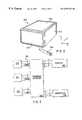
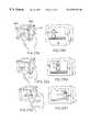
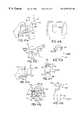
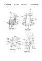
- FIG. 1is an illustration of a 3D controller having six force/touch sensitive sensors
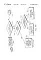
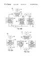
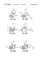
- FIG. 2is a block diagram of the control electronics of the 3D controller of FIG. 1;
- FIG. 3is an illustration of a 6D controller having three X-Y-position and force/touch sensitive sensors
- FIG. 4 aillustrates the user interface of the controller of FIG. 3 with regards to position information
- FIG. 4 billustrates the user interface of the controller of FIG. 3 with regards to rotational information
- FIG. 5is a block diagram of the control electronics of the 6D controller of FIG. 3;
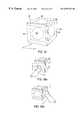
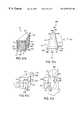
- FIG. 6illustrates a 6D controller having six X-Y-position and force/touch sensitive sensors
- FIG. 7illustrates a 6D controller having six X-Y-position and force/touch sensitive sensors and three knobs
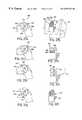
- FIG. 8is an expanded view of a “twist-mode” touch cylinder controller
- FIG. 9 ais an illustration of a “push-mode” touch cylinder controller
- FIG. 9 bis an illustration of sensing yaw with reference to the controller of FIG. 9 a;
- FIG. 9 cis an illustration of sensing roll with reference to the controller of FIG. 9 a;
- FIG. 9 dis an illustration of sensing pitch with reference to the controller of FIG. 9 a;
- FIGS. 10 a, 10 b, and 10 care illustrations of sensing X-position, Y-position and Z-position respectively in a “drag-mode”;
- FIG. 11illustrates a pipe-crawler controller
- FIG. 12illustrates a pipe-crawler robot
- FIG. 13illustrates a shape variation of controller 705 adapted for easy uses of a stylus
- FIG. 14illustrates a shape variation of controller 705 adapted for use with CAD/CAM digitizers
- FIG. 15illustrates the combination of two force-sensitive sensors on a mouse
- FIG. 16illustrates a wedge controller adapted for use in controlling a mobile crane
- FIG. 17illustrates a mobile crane
- FIG. 18illustrates a controller for use in a spherical coordinate system
- FIG. 19illustrates a two-mode controller adapted for use in controlling an object or cursor in 2 dimensions
- FIGS. 20 a and 20 billustrate an alternative technique for generating rotation commands using the controller of FIG. 6;
- FIGS. 21 a, 21 b, 22 , 23 and 24illustrate techniques for generating rotation using the controller of FIG. 6;
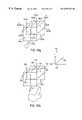
- FIG. 25 aillustrates a controller including 6 force-sensitive matrix sensors and 24 edge sensors
- FIG. 25 billustrates an alternative controller including 6 force-sensitive matrix sensors and 24 edge sensors;
- FIGS. 26 a - 26 fillustrate the protocol for rotation command generation using the controller of FIG. 25;
- FIG. 27illustrates a matrix sensor and four edge sensors used to detect rotation about an arbitrary axis in the X-Z plane
- FIGS. 28 a - 28 fillustrate the protocol for grasp-move gestures in conjunction with the controller of FIG. 25;
- FIGS. 29 a and 29 billustrate an alternative cylinder controller
- FIG. 30is a flow diagram illustrating the interpretation of touch points on a controller when there is no detection of touches on the matrix-sensors
- FIG. 31is a flow diagram illustrating the interpretation of touch points on a controller when there is a detection of a single touch point on a matrix-sensor
- FIG. 31 aillustrates a specified region on the controller of the present invention
- FIG. 32is a flow diagram illustrating the interpretation of touch points on a controller when there is a detection of multiple touch point on matrix-sensors
- FIGS. 33 a 1 , 33 a 2 , 33 b 1 , 33 b 2 , 33 c 1 , 33 c 2 , 33 d 1 , 33 d 2 , 33 d 3 , 33 d 4 , 33 d 5 , 33 d 6 , 33 e 1 , and 33 e 2illustrate the interpretation of various gestures
- FIG. 34is a perspective view of a controller incorporating trackballs to control the positional movements and edge sensors to control the rotational movements of an object;
- FIGS. 34 a and 34 billustrate the generation of translation commands using the controller of FIG. 34;
- FIGS. 35 a - 35 dillustrate the use of a single face of the controller of the present invention to input commands in six degrees of freedom
- FIG. 35 eis a flow diagram illustrating the distinguishing of different input commands
- FIG. 36illustrates the simultaneous input in thirty-six possible degrees of freedom using six faces of the controller
- FIGS. 37 a - 37 pillustrate an example of controlling a virtual hand using multiple faces of the controller
- FIG. 38is flow diagram illustrating the manipulation of a virtual hand in a simulated 3-D environment
- FIG. 38 ais a flow diagram illustrating the step of FIG. 38 for generating camera view commands
- FIG. 38 bis a flow diagram illustrating the step of FIG. 38 for generating virtual hand movement commands
- FIG. 38 cis a flow diagram illustrating the step of FIG. 38 for generating virtual finger movement commands
- FIGS. 39 a - 39 dillustrate the manipulation of an object in a virtual environment using a virtual hand and the controller of the present invention
- FIGS. 40 a - 40 billustrate the user simultaneously commanding the rotation of two computer-generated objects using the controller
- FIGS. 41 a - 41 hillustrate deforming an object using multiple faces of the controller
- FIGS. 42 a - 42 fillustrate the manipulation of a cursor and an object in a CAD application program using the controller
- FIG. 43is a flow diagram illustrating the manipulation of a cursor and an object in the application program of FIG. 42 a-f;
- FIG. 43 ais a flow diagram illustrating the step of FIG. 43 of moving the cursor using the controller
- FIG. 43 bis a flow diagram illustrating the step of FIG. 43 of moving the object using the controller
- FIG. 43 cis a flow diagram illustrating the step of FIG. 43 of twisting the object using the controller
- FIG. 43 dis a flow diagram illustrating the step of FIG. 43 of shrinking or stretching the object using the controller
- FIGS. 44 a - 44 cillustrate the implementation of psuedo force feedback of the present invention
- FIGS. 45 a and 45 billustrate embodiments of the controller of the present invention including tactile sensation generators for active tactile feedback
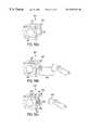
- FIG. 46 ais a front view of a controller in accordance with another embodiment of the present invention.
- FIG. 46 bis a side view of the controller from the right edge taken along line 46 b — 46 b of FIG. 46 a;
- FIG. 46 cillustrates a method of operating the controller of FIG. 46 a to produce an x,y translation signal in the Cartesian coordinate system
- FIG. 46 dillustrates a method of operating the controller of FIG. 46 a to produce a yaw and pitch rotation signal
- FIG. 46 eillustrates a method of operating the controller of FIG. 46 a to produce a series of z coordinates in the Cartesian coordinate system
- FIG. 46 fillustrates a method of operating the controller of FIG. 46 a to produce a roll rotation signal
- FIG. 46 gillustrates an embodiment of the controller of FIG. 46 a with an attached handle
- FIG. 46 hillustrates an embodiment of the controller of FIG. 46 a with a support
- FIG. 47 aillustrates a controller in accordance with yet another embodiment of the present invention.
- FIG. 47 bis a top view of the controller of FIG. 47 a;
- FIG. 47 cillustrates a method of operating the controller of FIG. 47 a to generate an x,y and z translation signal
- FIG. 47 dillustrates a method of operating the controller of FIG. 47 a to generate a pitch, yaw and roll rotation signal
- FIG. 47 e and FIG. 47 fillustrate a controller in accordance with yet another embodiment of the present invention.
- FIG. 47 gillustrates a method of operating the controller of FIG. 47 e to produce an x,y and z translation signal
- FIG. 47 hillustrates a method of operating the controller of FIG. 47 e to generate a pitch, yaw and roll rotation signal
- FIG. 48 ais a top view of a controller in accordance with yet another embodiment of the present invention.
- FIG. 48 billustrates a controller in accordance with yet another embodiment of the present invention.
- FIG. 48 cillustrates a method of operating the controller of FIG. 48 a to produce an x,y and z translation signal
- FIG. 48 dillustrates a method of operating the controller of FIG. 48 a to generate a pitch, yaw and roll rotation signal
- FIG. 48 eillustrates a method of operating the controller of FIG. 48 b to generate an x, y and z translation signal
- FIG. 48 fillustrates a method of operating the controller of FIG. 48 b to generate a pitch, yaw, and roll rotation signal
- FIGS. 49 a-fillustrate several different embodiments of a number of controllers 4315 a-f in accordance with the present invention
- FIG. 49 gillustrates a method of operating the controllers of FIGS. 49 a-f to generate an x, y or z translation signal
- FIG. 49 hillustrates a method of operating the controllers of FIGS. 49 a-f to generate a pitch, yaw or roll rotation signal
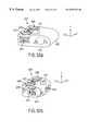
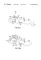
- FIG. 50 aillustrates a controller in accordance with yet another embodiment of the present invention
- FIG. 50 billustrates a controller in accordance with yet another embodiment of the present invention
- FIG. 50 cillustrates a controller in accordance with yet another embodiment of the present invention.
- FIG. 51 aillustrates a method of operating the controller of FIG. 50 c
- FIG. 51 billustrates an embodiment of the controller of FIG. 50 c with an attached handle 4166 ;
- FIG. 51 cillustrates an embodiment of the controller of FIG. 50 c with a support 4148 ;
- FIG. 52 aillustrates a mouse controller in accordance with yet another embodiment of the present invention
- FIG. 52 billustrates a mouse controller in accordance with yet another embodiment of the present invention
- FIG. 52 cillustrates a trackball controller in accordance with yet another embodiment of the present invention.
- FIG. 52 dillustrates a method for operating the trackball controller
- FIG. 53 aillustrates a controller in accordance with yet another embodiment of the present invention
- FIG. 53 b and FIG. 53 cillustrate a method of operating the controller of FIG. 53 a to produce x, y, z, pitch, yaw, and roll rotation signals;
- FIGS. 53 d-killustrate a method of operating the controller of FIG. 53 a to generate rotation signals
- FIG. 54is a flow chart of a method 4460 of generating translation, rotation and continuation signals from the controllers of the present invention.
- FIG. 1is an illustration of a force/touch sensitive 3D controller in accordance with a first embodiment of the present invention.
- a controller 105is shaped substantially in the form of a cube having six faces or sides, i.e. controller 105 can be provided as a cube shape or other similar shapes, such as a rectilinear object or cube having rounded edges or the like. Alternatively, controller 105 can have other shapes.
- a first force-sensitive sensor pad 110is positioned on the front face of controller 105 .
- a second force-sensitive sensor pad 115is positioned on the right side of controller 105 .
- a third force-sensitive sensor pad 120is positioned on the top side of controller 105 .
- a fourth force-sensitive sensor pad 125is positioned on the left side of controller 105 .
- a fifth force-sensitive sensor pad 130is positioned on the back side of controller 105 .
- a sixth force-sensitive sensor pad 135is positioned on the bottom side of controller 105 .
- a frame 140is attached to the edge of controller 105 between the bottom and back surfaces, allowing access to all six surfaces of controller 105 .
- Control harness 145is coupled to the six force-sensitive sensor pads 110 , 115 , 120 , 125 , 130 , and 135 and provides signals in response to the application of pressure to the pads.
- the signalsare preferably input to a computer system or object controlled by the controller 105 .
- the computer systemfor example, can display a computer-generated object that can be manipulated in simulated space by the controller 105 . Alternatively, a real object, such as a crane, can be manipulated by the controller 105 .
- Controller 105is operated by pressing on any of the six force-sensitive pads. This pressure is preferably applied with one or more of the user's fingers. Alternatively, other objects can be used to apply pressure, such as a stylus or other article.
- the sensor padscan detect even a small amount of pressure so that the user need only touch the pads.
- the planar faces and the sensor pads of the controller 105are rigid and do not substantially deforn under the pressure from the user. Thus, accurate x, y, and z-axis commands, referenced to the faces of the controller, can be provided at any point touched on the sensor pads.
- the user interfaceis intuitive since a real or computer generated object will move as if it is responding to the pressure (i.e., force) on controller 105 .
- pressurei.e., force
- pressing down on force-sensitive pad 120positioned on the top of controller 105 , will cause a controlled object to move downward ( ⁇ Y).
- pressing up on force-sensitive pad 135positioned on the bottom of controller 105 , will cause the object to move upward (+Y). Pressing the controller towards the user, by pressing on force-sensitive pad 130 , positioned on the back of controller 105 , will cause the object to move towards the user ( ⁇ Z).
- Pressing the controller away from the userby pressing on force-sensitive pad 110 , positioned on the front of controller 105 , will cause the object to move away from the user (+Z). Pressing the controller to the left, by pressing on force-sensitive pad 115 on the right side of controller 105 , will cause the object to move to the left ( ⁇ X). Similarly, pressing the controller to the right, by pressing on force-sensitive pad 125 , positioned on the left side of controller 105 , will cause the object to move to the right (+X).
- controller 105exhibits a zero neutral force, i.e., the controller does not require a force on any sensors or mechanical members to maintain a neutral position. The user merely stops applying pressure to the sensors, and the controller is in a neutral state that does not input movement signals to the computer 220 .
- FIG. 2illustrates a block diagram of the controller electronics used to provide 3D position information in conjunction with the controller of FIG. 1 .
- Force sensitive pads 110 , 115 , 120 , 125 , 130 , and 135are coupled to control harness 145 , which couples all six force-sensitive pads to A/D converter 205 .
- A/D converter 205converts the analog signals from each of the force-sensitive pads into digital signals.
- the six digitized signalsare coupled to integrator 210 .
- the three position signals X, Y and Zare then coupled to a computer 220 to control the position of a cursor or object displayed on a display device coupled to the computer 220 .
- the position signalscan be used for servo controls for heavy equipment, such as crane servo motors 230 .
- controller 105is sensitive to the presence of a touch input and A/D converter 205 provides a binary signal output to integrator 210 for each force-sensitive pad.
- Thisprovides a controller that provides a single “speed”, that is, activation of a force-sensitive pad will result in the cursor, object or equipment moving in the desired direction at a certain speed.
- force-sensitive pads 110 , 115 , 120 , 125 , 130 and 135can be of the type that provide analog outputs responsive to the magnitude of the applied force
- A/D converter 205can be of the type that provides a multi-bit digital signal
- integrator 210can be of the type that integrates multi-bit values.
- the use of a multi-bit signalsallows for multiple “speeds,” that is, the speed of the cursor or object movement in a given direction will be responsive to the magnitude of the force applied to the corresponding force-sensitive pads.
- FIG. 3is an illustration of a force/touch sensitive 6D controller in accordance with a second embodiment of the present invention.
- Controller 305is also shaped in the form of a cube, however this controller uses three force-sensitive matrix sensors.
- a first force-sensitive matrix sensor 310is positioned on the front of controller 305 .
- Sensor 310provides two analog signals in response to the position of an applied force, which provides X and Y position information as illustrated in FIG. 4 a.
- Sensor 310also provides a third signal in response to the magnitude of the force applied to sensor 310 .
- a second force-sensitive matrix sensor 315is positioned on the right side of controller 305 .
- Sensor 315provides two analog signals in response to the position of the force applied to sensor 315 , which will be interpreted by control electronics to provide Y and Z information as illustrated in FIG. 4 a. Sensor 315 also provides a third signal responsive to the magnitude of the force applied to sensor 315 .
- a third force-sensitive matrix sensor 320is positioned on the top side of controller 305 . Sensor 320 provides two analog signals in response to the position of the force applied to sensor 320 , which will be interpreted by the control electronics to provide Z and X information as illustrated in FIG. 4 a.
- sensors 310 , 315 and 320provide redundant X, Y and Z position control of a cursor, object or equipment. That is, Y-position information can be entered on either sensor 310 or 315 , X-position information can be entered on either sensor 310 or 320 , and Z-position information can be entered on either sensor 315 or 320 .
- the two X inputsare summed to provide the final X position information.
- Y and Z informationis obtained in the same manner.
- a change in position on a sensoris interpreted as a change of position of the real or computer-generated object, with a fixed or programmable gain.
- sensors 310 , 315 and 320also provide the pitch, yaw and roll control.
- the third signal provided by each sensoris used to differentiate “light” from “strong” pressures on each sensors.
- Threshold detector 535illustrated in FIG. 5, receives the third signal from each sensor and couples the related two analog signals to either position interpreter 540 or to orientation interpreter 545 in response to the third signal being “light” or “strong” respectively.
- a pressure exceeding a pre-defined thresholdis detected, it is interpreted as a “strong” pressure, i.e., an orientation “gesture”, and the two analog signals from the affected sensor are used to provide orientation information.
- the two analog signals from sensor 310are used to provide pitch information about the Z-axis, as indicated by the arrow on sensor 310 .
- the two analog signals from sensor 315are used to provide roll information about the X-axis.
- the two analog signals from sensor 320are used to provide pitch information about the Y-axis.
- other types of inputcan be provided on sensors 310 , 315 , and 320 to command rotation of the controlled object.
- trajectory gesturescan be input, such as the circle gesture described in FIG. 35 d, to generate a sequence of positive/negative angle changes and cause the controlled object to rotate.
- a winding, snake-like gesturewould cause the controlled object to rotate in alternating directions about an axis.
- FIG. 5is a block diagram of the control electronics of the 6D controller of FIG. 3 .
- Force-sensitive matrix sensors 310 , 315 , and 320are coupled to control harness 510 , which couples all three force-sensitive matrix sensors to threshold detector 535 .
- a threshold detector 535directs sensor information to either position interpreter 540 or orientation interpreter 545 in response to the magnitude of the force signal.
- Position interpreter 540can operate in either of two modes. In an absolute mode, the position of the X-signal is directly translated to the X-position of the cursor or object. If two inputs are present the inputs can be either averaged or the second ignored. In a relative mode, position interpreter 540 responds only to changes in X-values. Again, if two inputs are present they can either be averaged or the second input ignored. The Y and Z information is obtained in a similar manner.
- Orientation interpreter 545interprets rotational “gestures” as rotational control signals. More specifically, when a user applies pressure above the threshold pressure as detected by threshold detector 535 , the analog information from the affected sensor is coupled to orientation interpreter 545 and interpreted as an orientation or rotation about the axis perpendicular to that sensor. The angular position of the pressure point is calculated with reference to the center point of the sensor. In a relative operating mode any angular changes are interpreted as rotations. The rotation can be modified by a programmable gain if desired.
- Orientation interpretercan also operate in an absolute mode. In an absolute mode, the orientation is determined from the two signals from each sensor by determining the angular position of the input relative to the center point of the sensor.
- FIG. 6illustrates a third embodiment of a 6D controller 605 .
- Controller 605is shaped substantially in the form of a cube.
- a first force-sensitive matrix sensor 610is positioned on the front of controller 605 .
- a second force-sensitive matrix sensor 615is positioned on the right side of controller 605 .
- a third force-sensitive matrix sensor 620is positioned on the top side of controller 605 .
- a fourth force-sensitive matrix sensor 625is positioned on the left side of controller 605 .
- a fifth force-sensitive matrix sensor 630is positioned on the back side of controller 605 .
- a sixth force-sensitive matrix sensor 635is positioned on the bottom side of controller 605 .
- a frame 640is attached to the edge of controller 605 between the bottom and back surfaces, allowing the user to access to all six surfaces of controller 605 .
- Control harness 645is coupled to force-sensitive matrix sensor 610 , 615 , 620 , 625 , 630 , and 635 and provides signals indicative of the magnitude and the position of the force applied to each sensor.
- the X, Y and Z position data and the orientation datais derived in the same way as described with reference to controller 305 illustrated in FIGS. 3 and 4.
- the additional sensorsprovide multiple redundant entry capabilities. Specifically, yaw information about the Z-axis can be provided by either sensor 610 or sensor 630 . Roll information about the X-axis can be provided by either sensor 615 or sensor 625 . Pitch information about the Y-axis can be provided by either sensor 620 or sensor 635 . Similarly, X-position information can be provided by sensors 610 , 620 , 630 and 635 . Y-position data can be provided by sensors 610 , 615 , 630 and 625 .
- Z-position datacan be provided by sensors 620 , 615 , 635 , and 625 .
- multiple inputscan be resolved either by averages or by ignoring secondary inputs. More specifically, priority can be given to specific sensors or priority can be given with regards to the relative time of the inputs. Further, inputs can be interpreted on either absolute or relative modes.
- rotation commandscan be generated by another technique using the 6-sided controller of FIG. 6 .
- a rotation commandis generated by simultaneously dragging a finger on one panel in a first direction, and dragging another finger on the opposite panel in the opposite direction.
- the user's thumb 2010is dragged vertically upward in a +Y direction on panel 610 .
- the user's forefinger 2020is dragged vertically downward in a ⁇ Y direction on panel 630 . This is interpreted as a positive rotation about the X-axis, as illustrated in FIG. 20 b, where a displayed (or controlled) object 2030 is rotated about the X-axis as illustrated.
- the position and change-of-position informationis detected separately for each of the six panels.
- the change-of-position informationis compared for the opposite panels. If the change-of-position information indicates that the touch points are moving in substantially opposite directions, a rotation command is generated. Rotation nominally corresponds to the rotation about the affected axis such that a single complete rotation of the touch points about the controller 605 would result in a single revolution of the image. Alternatively, magnifications could be used such that the image would be rotated by an amount proportional to the rotation of the touch points.
- FIG. 21 aillustrates the gesture corresponding to a negative rotation about the X-axis
- FIG. 21 billustrates the corresponding movement of display (or controlled) object 2030 .
- rotation commandsmay be provided about the X-axis by gesturing on panels 620 and 635 parallel to the Z-axis, as illustrated in FIG. 22 .
- rotation commandsmay be provided about the Z-axis by gesturing parallel to the X- and Y-axes on panels 615 , 620 , 625 and 635 as illustrated in FIG. 23, and about the Y-axis by gesturing parallel to the X- and Z-axes on panels 610 , 625 , 630 and 615 as illustrated in FIG. 24 .
- the interpretation of the gesturesis described more fully below in the section titled Gesture Interpretation.
- FIG. 7A fourth embodiment of a 6D controller 705 is illustrated in FIG. 7.
- a controller 705is shaped in the form of a cube with three attached knobs.
- Six force-sensitive matrix sensors 710 , 715 , 720 , 725 , 730 and 735are positioned on controller 705 in the same manner as explained in detail with regards to controller 605 illustrated in FIG. 6 . However, these force-sensitive matrix sensors are used only to generate position commands in the X, Y, and Z directions.
- Knobs 740 , 750 and 760provide the orientation information for roll, yaw and pitch. Specifically, knob 740 provides pitch information about the Y-axis, knob 750 provides roll information about the X-axis, and knob 760 provides yaw information about the Z-axis.
- each knobincludes at least one sensor pad that can detect one dimensional information about the circumference of the knob.
- each sensorcan average two inputs. Movement of one or two pressure points on a sensor is interpreted as rotation about the axis of that sensor. Thus each knob generates orientation information about one axis in response to twisting of a thumb and finger about that knob.
- sensor 745 on knob 740provides one-dimensional position information about the circumference of knob 740 .
- the rotational command(the change in rotation) is calculated as follows:
- ⁇is the rotational command
- Gis the programmable gain
- dlis the change in the average position of the fingers
- Lis the circumference of the knob.
- twisting the thumb and finger one centimeter on knob 740is interpreted as 90° of rotation about the Y-axis.
- the gaincan be increased or decreased as desired.
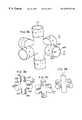
- FIG. 8is an expanded view of a touch cylinder 800 in accordance with another embodiment of the present invention.
- Touch cylinder 800provides X, Y, and Z position information in response to forces applied to force-sensitive sensors 801 , 802 , 803 , 804 , 805 , 806 positioned on the ends of six interconnected cylinders comprising touch cylinder 800 . These six sensors are coupled and operate in the same manner as the six force-sensitive pad of controller 105 described with reference to FIG. 1 .
- Touch cylinder 800provides orientation information in response to signals from sensors 810 , 811 , 812 , 813 , 814 and 815 . These sensors operate in the same manner as three knobs 740 , 750 and 760 of controller 705 described with reference to FIG. 7 with the multiple inputs for each axis summed.
- touch cylinder 900is constructed of six cylinders, each aligned along a Cartesian coordinate, and connected together at the origin of the Cartesian coordinate system.
- Each cylinderhas force-sensitive sensors on its end for position information as in touch cylinder 800 .
- touch cylinder 900derives rotational information in a different manner.
- the circumference of each cylinderis covered with a force-sensitive sensor that is divided into at least four sections.
- the cylinder aligned in the +X directionincludes sections 901 , 902 , 903 , and 904 . Each section covers 90° along the circumference of the cylinder.
- the other five cylindersare also covered by force-sensitive sensors each with four sections. As illustrated, the centers of each of the sections lie on a plane of the Cartesian coordinate system defined by the six cylinders.
- touch cylinder 900Operation of touch cylinder 900 is described with reference to a “push” mode. Specifically, rotational information is provided by “pushing” sensors positioned on the sides of the cylinders to rotate the object about one of the axes other than the one on the cylinder of the enabled sensor as if it had been “pushed” in the same direction as the controller. This is more easily explained by illustration. Referring to FIG. 9 b, a rotational yaw input about the Z-axis is provided by pressing any of sensors 902 , 904 , 905 , 906 , 907 , 908 , 909 or 910 .
- Sensors 904 , 906 , 908 , and 910provide a positive (counterclockwise) yaw signal
- sensors 902 , 905 , 907 and 909provide negative (clockwise) yaw signals.
- These signalscan be combined as described above, and the signals can be either “on/off” or have multiple levels.
- Roll and pitch informationis provided in a similar manner, as illustrated in simplified diagrams 9 c and 9 d.
- FIGS. 10 a - 10 cA third embodiment of a touch cylinder 1000 is illustrated in FIGS. 10 a - 10 c.
- touch cylinder 1000has no sensors on the ends of the six cylinders.
- Six sensors on the cylindersprovide orientation information in the same manner as the sensors 810 - 815 in touch cylinder 800 .
- the sensor pads of touch cylinder 1000are two-dimensional and provide information responsive to the position of pressure along the cylinders as well as in response to the position of the pressure around the circumference of each cylinder.
- FIG. 10 amovement of the thumb and forefinger along the X-axis cylinder in the X-direction is detected by sensor 1010 .
- the X-position information from the two inputsis averaged and used to provide a relative position input to the cursor or controlled object.
- Y-position informationis provided in a similar manner as illustrated in FIG. 10 b.
- Z-position informationis provided as illustrated in FIG. 10 c.
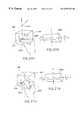
- FIG. 11illustrates a pipe-crawler controller 1100 in accordance with the present invention designed for applications in a cylindrical coordinate system.
- a pipe-crawling robotis illustrated in FIG. 12, where a robot 1205 is supported by three legs 1210 , 1215 , and 1220 carries a camera or ultrasound detector 1225 for inspecting interior surfaces of a pipe 1230 .
- Pipe-crawler controller 1100consists of three force-sensitive sensors 1105 , 1110 , and 1115 , each of which can detect position information is two dimensions and force.
- Z-position data along the cylinderis provided in response to the position of pressure along the Z-axis on sensor 1110 .
- Theta informationcan be obtained from the theta position information from sensor 1110 .
- Radial (r) informationis provided by the r position of pressure applied to sensors 1105 and 1115 .
- Z-positioncan be responsive to the force of signals applied to sensors 1105 and 1115 in a manner similar to controller 105 .
- Theta informationcan be obtained in a manner similar to that used for rotation information in controller 305 .
- Radial informationcan be obtained from the force of the pressure applied to sensor 1110 .
- FIG. 13illustrates a controller 1305 having a sloped front surface adapted to be more compatible with the use of a stylus.
- controller 1305includes an inclined front sensor 1310 .
- Position informationis obtained in a manner similar to that of controller 305 .
- the control inputsare not adjusted for the slope of the sensor, and movement of a pressure point on sensor 1310 will be interpreted identically as movement on sensor 310 of controller 305 .
- Rotation informationis provided by knobs 1315 , 1320 and 1325 in a manner similar to the operation of the knobs of controller 705 .
- FIG. 14illustrates a shape variation of controller 705 with an expanded sensor 1410 . This variation is adapted specifically for with in CAD/CAM digitizers.
- FIG. 15illustrates the combination of two force-sensitive sensors on a mouse 1505 .
- Mouse 1505operates in a conventional manner to provide X-position and Y-position control signals.
- Force-sensitive sensor 1510provides a signal for providing ⁇ Z information.
- force-sensitive sensor 1515provides a signal for providing +Z information.
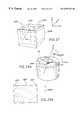
- FIG. 16illustrates a wedge controller 1605 adapted for use in controlling a crane such as mobile crane 1705 illustrated in FIG. 17 .
- Sensor pad 1610provides information in the X and Y directions and a third signal in response to the force of the applied pressure. The third signal is used provide a signal to rotate the boom 1705 in a counterclockwise direction, as if pressure was applied to the right side of the boom, “pushing” it counterclockwise.
- X-position information from sensor 1610controls the extension of boom end 1710 .
- Y-position information from sensor 1610controls the elevation of boom 1705 and boom end 1710 .
- Sensor pad 1615also provides information in the X and Y directions and a third signal in response to the force of the applied pressure.
- the third signalis used provide a signal to rotate boom 1705 in a clockwise direction, as if pressure was applied to the left side of the boom, “pushing” it clockwise.
- X-position information from sensor 1615controls the movement of outrigger 1715 of the mobile crane.
- Y-position information from sensor 1615controls hook cable 1720 .
- the correspondence between control inputs ends the operation of mobile crane 1705is also illustrated with reference to numerals 1 - 5 , with the numerals on controller 1605 referring to the X, Y or force of one of the two sensors, and the corresponding numeral illustrating the corresponding motion controlled with reference to mobile crane 1705 .
- FIG. 18illustrates a controller 1805 adapted for use in a spherical coordinate system.
- Controller 1805is in the shape of a hemisphere with a hemispherical surface 1810 and a flat bottom surface 1815 .
- Radial informationis provided in response to activation of a sensor-sensitive pad on surface 1815 .
- Theta and phi informationis provided in response to position information from a force-sensitive pad on surface 1810 .
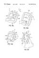
- FIG. 19illustrates a controller adapted for use in controlling an object or cursor in 2 dimensions.
- a force-sensitive matrix sensor 1905provides two signals, one X, and one Y, in response to the position of a force applied to the sensor.
- sensor 1905includes a raised area 1910 on its four edges which is preferably tactilely distinguished from flat surface 1915 of sensor 1905 by the inclination of area 1910 relative to surface 1915 .
- area 1910includes an area at each of the four edges of surface 1915 . The edges are inclined and raised relative to flat surface 1915 .
- Flat surface 1915is also referred to herein as a “main sensor area” while the edge portions can be referred to as “edge sensors”, even though there need only be a single matrix sensor used for both main and edge sensors (covering a whole face of the controller). Alternatively, separate sensors can be provided for the flat surface 1915 and the raised edges 1910 , as described with reference to FIG. 25 a.
- the raised edges of the controllerprovide an area of the sensor tactilely distinguished from flat surface 1915 which operates in a different mode.
- computer system 220reads input signals from coordinates of the edge sensor areas, it can distinguish this input as a different command from input entered on the main sensor areas.
- a change in position on sensor area 1915is interpreted as a proportional change in cursor or object position on a display device of the computer 220 .
- a steady force (without substantial movement) on edge sensor 1910is interpreted as a continuation of the cursor movement.
- Cursor movementcan be continued at either the most recent velocity along an axis, or at a preset speed, as long as a force is detected on the portion of edge sensor 1910 on that axis, such as portion 1920 with regards to movement in the positive X-direction.
- the speed of the cursor movement along an axiscould be proportional to the amount of force applied to edge sensor 1910 on that axis.
- area 1920would provide control of +X cursor speed
- area 1925would provide control of +Y cursor speed
- area 1930would provide control of ⁇ X cursor speed
- 1935would provide control of ⁇ Y cursor speed.
- the operatoris provided with the advantages of two alternative operating modes and the ability to combine the two modes in order to continue object movements in a desired direction after reaching the edge of main sensor area 1915 .
- the edge sensor inputcan be interpreted as a separate command and not as a continuation command.
- an object or cursorcan be rotated using the edge sensors, as described in greater detail below.
- only the edge sensorsare used, and the main sensor area does not provide input when touched.
- FIG. 25 aillustrates a controller 2500 that is similar to the controller illustrated in FIG. 19, except that it includes 6 force-sensitive matrix (“main”) sensors 2510 and 24 edge sensors 2520 . As illustrated in FIG. 25 a, there are four edge sensors 2520 surrounding and immediately adjacent to each of the force-sensitive main sensors 2510 . Three of the six matrix sensors 2510 and twelve of the twenty-four associated edge sensors 2520 are illustrated in FIG. 25 a. The three main sensors 2510 and the twelve associated edge sensors 2520 hidden in the perspective view are identical in construction and layout to those illustrated. The edge sensors provide separate input signals to the computer system 220 similarly to the main sensors so that user input on the edge sensors can be distinguished from input on the main sensors.
- mainforce-sensitive matrix
- edge sensors 2520surround and are immediately adjacent to each of the main sensors 2510 so that a user's finger may move continuously from a main sensor 2510 to an edge sensor 2520 .
- Each of the edge sensors 2520is inclined and raised relative to the adjacent main sensor to tactilely distinguish it from the associated main sensor 2510 .
- edge sensors 2520could be otherwise tactilely distinguished, such as by the use a texture different from that used on the adjacent main sensor 2510 .
- One function of the edge sensors 2520is to provide a continuation command as described above with regard to the operation of FIG. 19 .
- edge sensors 2520may be used to provide rotation commands.
- the eight edge sensors 2520 (x) parallel to the X-axismay be used to provided rotation commands about the X-axis.
- edge sensors 2520 xfour of these edge sensors ( 2520 x) provide a negative rotation command.
- edge sensors 2520 +xfour of these edge sensors ( 2520 +x) provide a positive rotation command.
- the eight edge sensors 2520 z parallel to the Z axisare used to provided rotation commands about the Z axis.
- the eight edge sensors 2520 y parallel to the Y-axisare used to provided rotation commands about the Y-axis.
- FIG. 25 billustrates an alternative embodiment of controller 2500 .
- FIG. 25 bhas thin film overlays, such as 2570 and 2571 , which provide a texture different from that of the main sensor pads, such as 2572 , 2573 , and 2574 .
- the thin film overlaycould be made of a sheet of polycarbonate to provide a smooth hard surface.
- thick neoprene or silicon rubbercould be used to provide a soft texture.
- a single matrix sensoris provided on each face of the controller, but the edge sensors are distinguished from the main sensors using the overlays 2570 and 2571 .
- FIGS. 26 a-fThe protocol for rotation command generation is illustrated in FIGS. 26 a-f.
- a rotation commandis generated in response to the user touching one or more of the edge sensors 2520 .
- FIG. 26 aillustrates a user touching two of the edge sensors 2520 (+x) which are located diagonally from each other on opposing faces of the controller 2500 . This results in the generation of a positive X-axis rotation command, which causes the rotation of, for example, a computer-generated object 2522 as illustrated in FIG. 26 b.
- FIG. 26 cillustrates generation of a positive Y-axis rotation command from the touching of diagonally-opposite edge sensors, resulting in the rotation of the computer-generated object 2522 as illustrated in FIG. 26 d.
- FIG. 26 aillustrates a positive Y-axis rotation command from the touching of diagonally-opposite edge sensors, resulting in the rotation of the computer-generated object 2522 as illustrated in FIG. 26 d.
- FIG. 26 aillustrates
- 26 eillustrates generation of a positive Z-axis rotation command, resulting in the rotation of object 2522 as illustrated in FIG. 26 f.
- Both positive and negative rotationsare provided in response to the detection of touch on the appropriate sensor edges 2520 .
- the magnitude of the force applied to the sensorsis preferably proportional to the amplitude of the rotation signal, such that a more powerful force on the edge sensors 2520 is interpreted as a more rapid rotation.
- Rotation commandsare distinguished from translation commands by determining if a touch on a main sensor 2510 at a position immediately adjacent to an edge sensor 2520 occurred immediately prior to or simultaneously with the initiation of the touch of an edge sensor 2520 . If touch points are detected on an edge sensor 2520 and on a main sensor 2510 , and the touch points are continuous in time and position, the user's intention is interpreted as a continuation of translation command. If touch points are detected on edge sensors 2520 only, without a prior and adjacent detection on the adjacent main sensor, then the magnitude of force signal on the edge will be interpreted as a rotational command.
- a certain amount of “hysterisis”is provided in the command interpretation, such that if a user partially touches a main sensor 2510 while applying a rotation gesture, it is not interpreted as a continuation of a translation command. This is easily accomplished, as a continuation of a translation command cannot occur unless a translation command had been previously provided, and that previous translation command is smoothly continued by the candidate continuation command. This is described more fully below in the section titled Gesture Interpretation.
- the rotation and continuous-translation input modesare very intuitive.
- the rotation modeis especially intuitive because the user's push action (one finger) or “twisting gesture” (pushing two diagonally opposite edge sensors by two fingers) of edges causes a controlled object to rotate in the pushing/twisting direction.
- Rotation commands about an arbitrary axismay also be generated using controller 2500 ′ similar to the controller 2500 illustrated in FIG. 25 a.
- edge sensors 2520are replaced with edge sensors 2520 ′ capable of providing a signal responsive to the position at which they are touched.
- edge sensors 2520 along the X-axisprovide a signal corresponding to the position along the X-axis at which a touch occurs.
- the edge sensors 2520 ′ along the Y- (and Z-) axisprovides a signal corresponding to the position along the Y- (and Z-) axis.
- Such position detection on the edge sensorscan provide a greater degree of control for user over the movement and manipulation of an object.
- FIG. 27is an illustration of the main sensor 2710 on top of controller 2700 in the X-Z plane and the 4 edge sensors 2720 immediately adjacent to the main sensor 2710 . If a touch is detected at the position “P1” indicated by “ 0 degrees” on edge sensor 2720 , a rotation command is generated corresponding to a rotation about the X-axis. However, a touch detected at an arbitrary position “P2” on edge sensor 2720 is interpreted as a rotation about the X′ axis, where the X′ axis is shifted by the same angle “phi” which corresponds to the angular displacement of point P 2 from the 0 degree reference position P 1 .
- a single touch pointis converted to a rotation about an arbitrary axis in the X-Z plane.
- Similar interpretation of touches on the edge sensors 2720 immediately adjacent to the matrix sensors 2710 in the Y-Z and X-Y planesprovide rotation commands about arbitrary Y′ axes in the X-Y plane and arbitrary Z′ axes in the Y-Z plane respectively.
- FIG. 28 aillustrates the use of a grasp/move gesture in conjunction with controller 2500 of FIG. 25 .
- a usersimultaneously touches main sensors 2810 and 2820 located on opposite sides of controller 2500 by applying pressure to the sensors 2810 and 2820 .
- the two opposing signalsare interpreted as a “grasp” command for a displayed (or controlled) object in the Y-Z plane, as illustrated in FIG. 28 b.
- the force signalcould be used as “remain-in-position” command (integral value of force signal is used as command), where the controlled object remains in its current position when user input is discontinued, or as “spring return” type command (magnitude of force signal for each time step is used as command), where the object moves in the direction of an origin position when user input is discontinued.
- the grasping limbs 2840 of claw 2835close upon the object 2845 as the user applies pressure as shown in FIG. 28 a.
- the usermay generate a translation command by dragging the touch points on panels 2810 and 2820 , as illustrated in FIG. 28 c.
- This gestureis interpreted as a simultaneous translation of claw 2835 while maintaining the previous grasp command, as illustrated in FIG. 28 d.
- the touch points of the user's fingersreach the edge of the main sensors 2810 and 2820 and move onto edge sensors 2850 and 2855 , the user may continue to move the claw 2835 because the detection of the user's fingers by the edge sensors is interpreted as the continuation of translation command, as illustrated in FIGS. 28 e and 28 f.
- pressure on the other panelsprovide commands for the X-Y and Y-Z planes.
- FIGS. 29 a and 29 bAn alternative embodiment of the cylinder of FIG. 11 is illustrated in FIGS. 29 a and 29 b.
- cylinder 2900includes a edge sensor 2910 raised and inclined relative to the flat main sensor 2920 .
- Rotation and translation continuation commandsare generated in the same manner as have been described with reference to controller 2500 .
- the displayed (or controlled) controlledis rotated about axis R′, where the axis R′ is in the plane of on the top surface 2920 of cylinder 3000 and shifted theta-90 degrees from reference axis R, where theta is the angle defined by the points P 1 and P 2 as illustrated.
- Gestures applied to the controllersmay be interpreted in a number of different ways by a computer interface and used to control the movement of display objects on an interactive computer display or used to control the movement of a physical piece of equipment, such as an industrial crane.
- the interpretation of gesturescan be broken down into 3 cases.
- step 3005is the entry point for the logic executed when no touch points are detected on main sensors 2510 .
- step 3010a test is conducted to determine if there are any touch points on edge sensors 2520 . If no, the logic is exited in step 3015 . If yes, step 3020 tests whether there are single touch points on edge sensors 2520 .
- the camera viewis rotated in step 3025 about the “i-axis”, which is either the x, y, or z-axis, depending on the edge sensor touched.
- the camera viewis the view of the virtual environment as, for example, displayed on a computer screen or the like.
- the rotation of the camera view with a single edge sensor touch pointis illustrated in FIGS. 33 a 1 and 33 a 2 .
- a testis conducted in step 3030 to determine if two touch points occur on parallel edge sensors, as shown in the example of FIGS. 26 a, 26 c, and 26 e. If yes, the camera view is rotated about the appropriate axis in step 3035 . If no, the camera view is simultaneously rotated about the two axes indicated by the touched edge sensors in step 3040 .
- step 3105is the entry point for the logic executed when a single touch point is detected on main sensors 2510 .
- a testis made to determine whether there are any touch points on any of the edge sensors 2520 . If no, the touch point is interpreted as a cursor translation in step 3115 , i.e., a cursor or object is moved in the direction of the touch point as determined by the trajectory of the touch point on the main sensor or by the direction of the single touch point (depending on the embodiment).
- a testis made in step 3130 to determine whether the touch point on a main sensor 2510 is within a specified region adjacent to the edge sensor 2520 on which a touch was detected, and whether a translation command has been just previously generated. This region 3132 of the main sensor 2510 is shown in FIG. 31 a. If yes, the gesture is interpreted as a continuation of the cursor or object translation in step 3135 . If no, the gesture is interpreted as a camera view rotation in step 3140 , similar to the camera rotation implemented in FIG. 30 .
- step 3205is the entry point for the logic executed when multiple touch points are detected on main sensors 2510 .
- step 3210a test is made to determine if any touch points are detected on edge sensors 2520 . If no, a test is made in step 3215 to determine if the finger dragging is occurring is significantly opposite directions and the touch pressure exceeds a threshold value. If yes, the gesture is interpreted as object grasp and rotation in step 3220 . (This gesture and its interpretation are illustrated in FIGS.
- step 3225determines if pressure on one touch point is significantly greater than another and exceeds the threshold value. If yes, the gesture is interpreted as an object grasp and translation along the appropriate axis in step 3230 .
- the pressure on back sensor 3227is stronger than the pressure on front sensor 3228 , so that the object and claw move along the Z axis in a negative direction.
- the pressure on front sensor 3228is stronger than the pressure on back sensor 3227 , so that the object and claw move along the Z axis in a positive direction. If the pressure of one touch point is not greater than the other, the gesture is interpreted as an object grasp and translation on the X-Y plane in step 3235 , as illustrated in FIGS. 33 d 5 and 33 d 6 .
- step 3240determines if there is only one touch point on edge sensor 2520 . If yes, the gesture is interpreted as an object grasp and rotation in step 3245 , as illustrated in FIGS. 33 b 1 and 33 b 2 . If no, a test is made in step 3250 to determine if the edges touched are parallel and if the touch points on the main sensor panel 2510 are within a specified region adjacent to the edge and whether there was a translation command just previously generated (similar to step 3130 of FIG. 31 ). If these tests are not all met, the gesture is interpreted as a camera view rotation in step 3255 .
- step 3260determines if three touch points occur on edge sensors 2520 . If yes, the gesture is interpreted as a continuation of object translation and object rotation in step 3265 , as illustrated in FIGS. 33 c 1 and 33 c 2 . If no, the gesture is interpreted as a continuation of object translation in step 3270 .
- the controllers described in FIGS. 1-10, 13 and 14are adapted for use in the Cartesian coordinate system. In general, they can be categorized by the modes used for position and rotation control. Specifically, a “push mode” for position control is used in the embodiments described with reference to FIGS. 1, 8 , and 9 a. In contrast, a “drag mode” for position is used in the embodiments described with reference to FIGS. 3, 6 , 7 , and 10 a-c. With regards to rotation, three general modes are used. “Gesture” mode for rotation is used in the embodiments described with reference to FIGS. 3 and 6. “Push mode” or “torque mode” for rotation is used in the embodiments described with reference to FIGS. 9 a-d.
- a “twist mode” for rotationis used in the embodiments described with reference to FIGS. 7 and 8. These modes can be combined in a number of ways as taught by the various embodiments. Further, different modes can be adapted to the cylindrical and spherical controllers taught with reference to FIGS. 11, 12 , 16 and 18 .
- FIG. 34illustrates an alternative design of a controller incorporating multiple trackballs and force sensitive edge sensors.
- This embodimentsupports the “drag mode” of translation commands by the use of trackballs 3410 , 3420 , and 3430 .
- trackball 3420 on the front “X-Y” surface of cube 3401is used to generate translation commands in the X-Y plane, as shown in FIG. 34 a.
- Trackball 3430 located on the “Y-Z” surface of controller 3401is used to generate translation commands in the Y-Z plane, as shown in FIG. 34 b.
- trackball 3410 on the “X-Y” surface of controller 3401is used to generate translation commands in the X-Z plane.
- Rotation commandsare generated as before, as in FIGS. 26 a-f and 33 b 1 , by the use of force sensitive edge sensors 3450 . As previously described, this can be implemented in either the “push” or “twist” mode.
- FIGS. 35 a - 35 dillustrate alternative functionality of the present invention. Controller 3500 can be used to provide up to 36 degrees of freedom according to the current embodiment. FIGS. 35 a - 35 d demonstrate how a single face of controller 3500 can be utilized to provide six degrees of freedom.
- FIG. 35 aillustrates a user's finger performing translation input on the main sensor 3508 of face 3502 of controller 3500 to provide input in three degrees of freedom along the x-, y-, and z-axes.
- Finger 3504(or another suitable pointer) can be moved in either direction along the x-axis 3510 as shown by arrows 3506 when touching main sensor 3508 to provide translation input in that degree of freedom.
- the usermight control a computer generated object to move left as the user's finger is moving left along the sensor 3508 .
- the user's finger 3504can be moved in either direction along the y-axis 3512 along main sensor 3508 as shown by arrows 3516 to provide input in the y degree of freedom.
- the user's finger 3504can be pushed against the main sensor 3508 in the direction of the z-axis shown by arrow 3518 to provide input in the z degree of freedom.
- a threshold pressuregreater than the pressure needed for movement in the x- and y-degrees of freedom, preferably commands the z-axis input, as described in greater detail below in FIG. 35 e.
- the z-axis inputis unidirectional, i.e., only movement in one direction along the z-axis can be input by the user when using just one face 3502 of the controller 3500 .
- various implementationscan assist the user in providing bi-directional movement along the z-axis, if desired, while using only one face 3502 .
- a “spring return” type commandcan be provided, as described above with reference to FIG. 28 b, where the position of the controlled object on the Z-axis (relative to an origin) is directly proportional to the amount of pressure applied to the main sensor. When pressure is removed, the object returns to the origin position.
- a “remain-in position” commandcan be provided as described above, where the controlled object moves along the Z-axis while the main sensor is touched, and the object stops at its current position when pressure is removed (optionally, the velocity of the object can be proportional to the amount of force on the main sensor).
- a special command input by the user on the controllercan toggle the desired direction along the z-axis.
- the defaultcan be +Z movement, and the user can tap the main sensor to subsequently command ⁇ Z movement.
- a separate peripheral devicesuch as a button on controller 3500 or a device separate from cube 3500 can toggle the z-axis direction.
- faces of the controller 3500are not being used for separate, independent input, then those faces can be used to provide the bi-directional z-axis movement, as described in the embodiments above.
- FIG. 35 billustrates a user's finger 3504 providing input for a rotary degree of freedom on face 3502 of controller 3500 .
- the userprovides pitch input, i.e., rotational input about the x-axis 3510 , by pressing either one of the edge sensors 3520 a or 3520 b with a finger 3504 . If edge sensor 3520 a is pressed, then pitch input in the direction shown by arrow 3522 is provided, and if edge sensor 3520 b is pressed, then pitch input in the direction shown by arrow 3524 is provided. If the user is moving finger 3504 on main sensor 3508 to provide translational input as in FIG.
- the translational inputcan be continued as described above, rather than providing rotational input (while the user continually presses the edge sensor). If the user presses edge sensor 3520 a or 3520 b discretely and without continuing previous translation movement on main sensor 3508 , then the pitch rotary input is provided. If the user presses two or more edge sensors simultaneously, then a combined rotary command will be input; for example, a simultaneous yaw and pitch rotation of the controlled object is commanded. Some types of sensors, however, do not have the ability to discriminate between multiple touch points; these types of sensors may average the analog position and force data between the multiple points. If such is the case, then the user should avoid providing more than one touch point at once to avoid undesired averaged input commands.
- FIG. 35 cillustrates a user's finger 3504 providing input for a rotary degree of freedom about the y-axis 3512 , i.e., yaw input about the y-axis, which is similarly implemented to the pitch input of FIG. 35 b.
- the userpresses either one of edge sensors 3526 a or 3526 b. If edge sensor 3526 a is pressed, then yaw input in the direction shown by arrow 3528 is provided, and if edge sensor 3526 b is pressed, then yaw input in the direction shown by arrow 3530 is provided.
- FIG. 35 dillustrates a user's finger 3504 providing input for a rotary degree of freedom about the z-axis 3514 , i.e., roll input.
- the usertraces his or her finger 3504 in an approximately circular gesture while touching main sensor 3508 .
- the direction of the gestureindicates the direction of the input about the z-axis.
- arrow 3532indicates clockwise input about the z-axis.
- the usercould provide counterclockwise input by inputting a gesture in the direction opposite to arrow 3532 .
- the receiving computer 220detects the angular change in the user's finger gesture and rotates the object a corresponding amount.
- the receiving computer 220detects a threshold pressure of the user's finger on main sensor 3508 before determining that a circular gesture is being input rather than translational commands, as described below with reference to FIG. 35 e.
- the six degrees of freedom provided by a single face 3502 of controller 3500can be multiplied by the number of active faces on the cube to achieve the total number of degrees of freedom in which the user may simultaneously provide input to a computer system or controlled device, e.g., when all six faces are used, there are 36 degrees of freedom.
- the usercan independently and simultaneously control multiple sets of six degrees of freedom.
- FIG. 35 eis a flow diagram illustrating how the different input commands of FIGS. 35 a and 35 d are distinguished.
- the processbegins at 3531 .
- the force Fis read from the user's touch point input on the main sensor of the controller.
- the processchecks whether the force F is less than a first threshold (threshold # 1 ). If so, then in step 3535 the x and y data of the detected touch point is used for an translation command along the x- and/or y-axes, as described above with reference to FIG. 35 a. After the detection of step 3534 , the force F is not.needed to implement the translation command.
- the processis then complete at 3541 .
- step 3536the process checks whether the force F is between the first threshold and a second force threshold (threshold # 2 ). If so, the force F is used to implement bi-directional z-axis movement, as described for FIG. 35 a, and the x and y data is not needed (although in some embodiments, the z-axis movement can use x- and y-data to help determine the direction of z-axis translation). For example, a spring-return type command can be used, or a remain-in-position command with the use of a finger tap input gesture. The process is then complete at 3541 .
- step 3539the x- and y-data of the touch point is used to determine the amount of roll that commanded by the user as described in FIG. 35 d.
- the F datais typically not needed to determine the change in angle of roll of the controlled object.
- a preferred method of calculating the rolluses the following formula:
- ⁇is the change in angle of roll of the controlled object
- (X 1 , Y 1 )is the starting touch point of the roll gesture
- (X 2 , Y 2 )is the ending point of the roll gesture.
- FIG. 36illustrates the user using both hands to provide input for 36 degrees of freedom.
- a separate fingercan be applied to each face of the controller 3500 .
- Thisallows much more control than in previous 3-D input devices, which typically offer a maximum of six degrees of freedom no matter if the user uses multiple fingers or hands.
- the high number of degrees of freedom in the present inventioncan be used to provide simultaneous manipulation of two or more independent objects in 3-D space. In previous input devices, only a single object or point can be controlled by the user at any one time.
- FIGS. 37 a-pillustrate an example of simultaneous control of multiple objects in 3-D space using the controller 3500 .
- the useris touching front face 3540 with finger 3542 , top face 3544 with finger 3546 , and back face 3548 with finger 3550 in order to manipulate 3-D objects.
- FIG. 37 bshows an example of a display screen 3560 which displays a virtual hand 3562 and is coupled to computer system 220 that is also coupled to controller 3500 .
- each finger or group of fingerscan be manipulated with a separate face of the controller in simulated 3-D space.
- each of the user's fingerscontrols a corresponding finger (or group of fingers) of the virtual hand 3562 .
- FIG. 37 cshows the user pressing face 3548 of the controller with middle finger 3550 as shown by arrow 3580 .
- the middle finger 3568 , ring finger 3566 , and pinky finger 3564 of the virtual hand 3562simultaneously curl downward as shown by arrows 3578 , in a “grasping gesture.”
- the moving fingers and handcould grasp the object.
- the speed of the curling fingersin some embodiments, can be related to the amount of pressure exerted by the user on the main sensor.
- the usercan also provide translation commands and rotation commands on face 3548 as described with reference to FIGS.
- 35 a-dto manipulate the tips of fingers 3564 , 3566 , and 3568 in any direction or orientation; this is described in greater detail below.
- Software implemented by computer system 220can model the virtual hand so that the fingers can be moved only in ways corresponding to fingers of an actual human hand. Alternatively, other hand models might allow the fingers to move in a variety of ways not possible for real hands.
- each finger 3564 , 3566 , and 3568can be controlled independently of the other fingers by a separate face of the controller.
- pinky finger 3564can be controlled by the left face of cube 3500
- ring finger 3566can be controlled by the bottom face of cube 3500
- the middle finger 3568can be controlled by the back face 3548 of controller 3500 .
- such an arrangementis somewhat awkward for the user to manipulate with one hand, so that the user finger-virtual finger correspondence would be difficult to maintain.
- FIG. 37 eillustrates the user pressing face 3544 of the controller with the user's index finger as shown by arrow 3582 .
- the virtual index finger 3570curls downward as shown by arrow 3584 .
- the movement of index finger 3570 of the virtual hand 3562is preferably correlated with movement of the user's index finger 3546 to provide an intuitive and easily-manipulated virtual hand.
- the index fingercan be manipulated with various movements in the six degrees of freedom provided by face 3544 .
- FIG. 37 gillustrates the user pressing face 3540 of the controller with the user's thumb 3542 as shown by arrow 3586 .
- the virtual thumb 3572 of the virtual hand 3562curls downward as shown by arrow 3588 similarly to the index finger 3570 described above.
- FIG. 37 iillustrates the user dragging his or her index finger 3546 along the main sensor of face 3544 along the x-axis 3510 as shown by arrow 3590 .
- the tip of index finger 3570 of the virtual hand 3562moves along a corresponding x-axis 3592 in the virtual environment, as shown by arrow 3594 .
- the distance that the index finger 3570 movesis preferably proportional to the distance that the finger 3546 is dragged.
- the other faces 3540 and 3548preferably control corresponding fingers of virtual hand 3562 in a similar fashion.
- FIG. 37 killustrates the user dragging his or her index finger 3546 along the main sensor of face 3544 along the y-axis 3512 as shown by arrow 3596 .
- the tip of index finger 3570 of virtual hand 3562moves along a corresponding y-axis 3598 so that the finger 3570 bends in a natural-looking fashion, i.e., the finger can pivot on a simulated knuckle joint 3600 when the tip of the finger is moved.
- FIG. 37 millustrates the user pressing two faces of controller 3500 simultaneously to demonstrate a hand gesture.
- Top face 3544which controls index finger 3570 of virtual hand 3562
- front face 3540which controls thumb 3572
- FIG. 37 nwhere the index finger 3570 and the thumb 3572 of the virtual hand curl together into a “pinching” gesture, shown by arrows 3571 .
- the usercan relieve the pressure on the sensors of the cube 3500 to allow the fingers 3570 and 3572 to uncurl and move apart.
- the usercan press additional or other faces simultaneously to move different fingers of virtual hand 3562 into different gestures and signs.
- controller 3500provides an intuitive interface to control virtual objects such as a hand with enough flexibility to provide, for example, signs in sign language or other complex hand manipulations.
- virtual objectssuch as a hand with enough flexibility to provide, for example, signs in sign language or other complex hand manipulations.
- pinching, pointing, or other gestures made with fingers of virtual hand 3562can imitate a variety of signs used in sign language.
- the feature of complex hand manipulationcan be especially useful in virtual reality settings, where the user controls objects or instruments such as virtual hand 3562 in complex ways to manipulate other virtual objects in the virtual reality setting, such as pushing or pulling objects, grasping objects, pushing buttons, turning dials, moving levers, etc.
- FIG. 37 oillustrates the user manipulating virtual hand 3562 using edge sensors of controller 3500 .
- the index finger 3546 of the useris used to touch edge sensor 3604 on the top surface 3544 of the controller. Since the top surface 3544 controls the index finger of virtual hand 3562 , the index finger 3570 rotates about the x-axis 3510 as shown in FIG. 3 p. Since the edge sensor was pressed, the whole finger bends down from the lower joint 3606 of the index finger and remains straight as it bends, as indicated by arrow 3608 . In some embodiments, if edge sensor 3610 were pressed, the finger 3570 could be bent down in the opposite direction if such non-natural movement were allowed in the simulation.
- FIG. 38is a flow diagram illustrating a method 3610 of providing the finger manipulation of virtual hand 3562 shown in FIGS. 37 b - 37 p.
- the methodbegins at 3612 , and, in step 3614 , signals from the six sensor pads on controller 3500 are read by the controlling computer system 220 .
- sensors on some of the faces of the cubecan be disabled, and the computer would not be required to check for input from the disabled sensor pads.
- step 3616the process checks whether any touch points have been detected from the user pressing fingers (or other objects) on the sensor pads. If a single touch point has been detected, i.e., the user is pressing only one sensor pad, then the process continues to step 3618 , in which a camera view control command is generated.
- This camera view control commandrotates or translates the view as seen by the user in a display such as display screen 3560 .
- the control commandis sent to the appropriate destination to implement the command.
- a microprocessor in the controlling computer system 220can receive the control command and generate a proper response by rotating or translating the camera view on display screen 3560 .
- Step 3618is described in greater detail with respect to FIG. 38 a.
- the processthen returns to step 3614 to read the six sensor pads.
- a virtual hand movement commandis generated. This type of command causes the entire virtual hand 3562 to move in three-dimensional space (the simulated space may have less than three dimensions if the simulation is so constrained).
- the virtual hand commandis then implemented, e.g., the computer system moves the hand 3562 to correspond to the current position of the user's finger on a main sensor pad, or continues to move the hand if the user's finger is on an edge sensor after a translation command, as described in the embodiments above.
- the generation of virtual hand control commandsis described in greater detail with respect to FIG. 38 b.
- the processthen returns to step 3614 to read the six sensor pads.
- step 3616determines that three or more touch points have been detected in step 3616 . If the process determines that three or more touch points have been detected in step 3616 , then the process continues to step 3622 , where a virtual finger movement command is generated.
- This type of commandcauses one or more fingers of hand 3562 to move in three dimensional space.
- the commandis implemented, e.g., by computer displaying the finger moving in the appropriate manner.
- the generation of virtual finger controlsis described in greater detail with respect to FIG. 38 c.
- the processthen returns to step 3614 to read the sensor pads.
- FIG. 38 ais a flow diagram illustrating step 3618 of FIG. 38, in which a “camera view” control command is generated.
- the processbegins at 3626 , and it is checked whether the detected single touch point is located at an edge sensor of controller 3500 in step 3628 . If so, then, in step 3630 , the touch point is interpreted as a rotation command to rotate the camera view in the direction corresponding to the edge sensor touched. For example, if the user presses top face edge sensor 3604 as shown in FIG. 37 a without touching any other sensors on controller 3500 , then the camera view will rotate about the x axis. If the other edge sensor on top face 3544 is pressed, the camera view rotates in the opposite direction about the x-axis. This is similar to the example of FIG. 33 a 2 , above. The process is then complete as indicated at 3634 and returns to the main process of FIG. 38 .
- step 3632a translation command for the camera view is implemented corresponding to the trajectory of the touch point on the sensor pad. For example, the last-processed touch point on the pad is examined and compared to the current touch point. From these two touch points, a vector can be determined and the view shown on the display device is translated along the vector, as if a camera were being translated by which the user was viewing the scene. The process is then complete at 3634 and returns to the process of FIG. 38 .
- FIG. 38 bis a flow diagram illustrating step 3620 of FIG. 38, in which a virtual hand movement command is generated.
- the processbegins at 3640 , and in step 3642 , the process checks whether the two detected touch points are located on diagonally-located edge sensors. For example, the illustrations of FIGS. 26 a, 26 c, and 26 e show the user touching such diagonally-located edge sensors. If so, the process continues to step 3644 , where a rotation command for the virtual hand is provided in the direction corresponding to the edge sensors touched. Thus, the entire hand 3562 will rotate about the x-, y- or z-axis as described with reference to FIGS. 26 a-f. The process is then complete at 3648 and returns to the main process of FIG. 38 .
- step 3646a translation command for the virtual hand is implemented that corresponds to the trajectory of both touch points on the controller.
- the virtual handis moved in directions corresponding to the touch points. For example, as shown above in FIGS. 33 d 5 and 33 d 6 , the two fingers on opposite faces of the controller cause the hand to translate in a plane. This is typically the most common form of input method to translate the virtual hand.
- the virtual handis moved along a vector resulting from corresponding component vectors along the x- and y-axes. If one finger is not moved and the other finger is dragged, then the virtual hand is translated according to the one finger that is being dragged. After step 3646 , the process is complete at 3648 and returns to the main process of FIG. 38 .
- FIG. 38 cis a flow diagram illustrating step 3622 of FIG. 38, in which a virtual finger movement command is generated.
- the processbegins at 3652 , and in step 3654 , the process checks for certain conditions of the touch points. If the touch pressure of one or more of the three detected touch points on main sensors is greater than a user-defined threshold pressure value, then the process continues to step 3656 , where a bending command of the first and second joints of the appropriate virtual finger(s) is generated so that a “grasp” action of the virtual hand is implemented as shown in FIGS. 37 d, 37 f, and 37 h. For example, if only one of the three detected touch points is above the threshold pressure, then only the corresponding virtual finger is moved.
- step 3656the process is complete at 3672 and returns to the main process of FIG. 38 .
- the processalso checks if the force of the user's touch points on main sensors is 5 less than the user-defined threshold value at step 3654 . As explained above, multiple fingers can be simultaneously dragged on the main sensors of different faces of the controller. If the touch point is less than the threshold, then step 3660 is performed, in which the process checks if the touch trajectory is along the x-axis and/or the y-axis of the controller. If along the x-axis, step 3662 is performed, in which a bending control command is generated to bend the two (or more) joints of the appropriate virtual finger(s) about the z-axis, thus providing x-axis translation of the tip of the virtual finger. An example of this motion is shown in FIGS. 37 j and 37 l .
- step 3672the process is complete at 3672 returns to the process of FIG. 38 . If the touch trajectory is along the y-axis in step 3660 , then the process provides a bending command for the joints of the virtual finger to implement a bend of the appropriate virtual finger about the x-axis of the hand, thereby providing y-axis translation of the tip of the finger. Simultaneous implementation of steps 3664 and 3662 for x-axis and y-axis translations can also be provided. The process is then complete at 3672 and returns to the process of FIG. 38 .
- the processalso checks in step 3654 if any of the detected touch points are on a edge sensor of the controller that is predetermined to correspond with a virtual finger.
- a virtual fingerAs explained above with reference to FIGS. 37 o and 37 p, the pressing of an edge sensor causes a virtual finger to move about the lower joint of the finger while remaining pointing straight, i.e., a “pointing gesture” is performed by the virtual hand.
- a touch pointis on a predetermined edge sensor, then in step 3668 , a bending command is provided about the second, lower joint of the appropriate virtual finger to generate the pointing action.
- the processis then complete at 3672 and returns to the process of FIG. 38 .
- the above processprovides a large and flexible range of virtual hand and virtual finger motions to the user with the intuitive use of the controller.
- the controllerallows fingers and the hand to controlled simultaneously and independently of each other, allowing a user to realistically perform virtual actions and interact with virtual objects in a highly realistic manner.
- FIGS. 39 a - 39 dillustrate an example of the use of the controller 3500 for manipulating virtual hand 3562 and a virtual object.
- the useris pressing three faces of the controller 3500 similarly to the examples shown in FIGS. 37 a - 37 e.
- display device 3560is shown displaying virtual hand 3562 which is grasping a virtual gun 3680 .
- the usermay have manipulated virtual hand 3562 with controller 3500 to close around the grip of virtual gun 3680 by pressing on main sensors 3548 and 3540 to cause virtual thumb 3572 and the three virtual fingers 3564 , 3566 , and 3568 to close around the grip of the virtual gun.
- the usercan also provide two points on controller 3500 to translate the virtual hand 3562 through the simulated 3-D environment displayed on the screen, as described with reference to FIG. 38 . In this way, the user can “carry” the gun 3680 through the virtual environment.
- FIG. 39 cillustrates the user pressing top face 3544 with finger 3546 with a pressure greater than the threshold pressure. This causes the virtual index finger 3570 of virtual hand 3562 to curl downward in a grasping gesture. This,.in turn, presses trigger 3682 of the virtual gun and causes a bullet 3684 to be fired from the gun 3680 . Manipulations of objects, such as the virtual gun, are thus made straightforward and intuitive using controller 3500 .
- FIGS. 40 a and 40 billustrate another example of controlling multiple objects simultaneously.
- a useris manipulating several faces of controller 3500 and inputting control commands to a computer system such as computer 220 .
- a display device 3710is coupled to the same computer system and displays two computer-generated objects 3712 and 3714 .
- the userpresses the diagonally-located edge sensors 3716 and 3718 , located on the front face 3540 and back face 3548 , respectively, of the controller to provide a rotation command to the computer system, which then rotates displayed object 3712 in the direction of arrow 3713 . This rotation is similar to that described with reference to FIGS. 26 a-f.
- edge sensors 3716 and 3718simultaneously with the pressing of edge sensors 3716 and 3718 , the user is pressing diagonally-located edge sensors 3720 and 3722 , located on the top face 3544 and bottom face 3545 , respectively, of controller 3500 .
- the touching of edge sensors 3720 and 3722causes object 3714 to rotate in the direction of arrow 3724 .
- the objects 3712 and 3714are able to connect to each other only if predetermined angular velocities are achieved for the two objects. Thus, simultaneous rotation of the two objects is required. Similar simulations, games, or other activities can be performed by controlling multiple objects simultaneously with controller 3500 .
- FIGS. 41 a - 41 hillustrate the use of controller 3500 in the manipulation and deformation of the appearance or shape of objects. Since multiple faces can be simultaneously controlled by the user, multiple points of objects can be simultaneously manipulated.
- FIG. 41 aillustrates a user manipulating four faces, top face 3544 , front face 3540 , back face 3548 , and bottom face 3545 of controller 3500 simultaneously.
- FIG. 41 bshows a display device 3710 displaying an object 3730 that is to be manipulated by the user.
- the userpresses the main sensor of front face 3540 with a stronger push of finger 3542 , and presses the main sensor of back face 3548 with a weaker push of finger 3550 .
- This finger inputcauses a shaping command to be input to the controlling computer 220 , and distorts the shape of object 3730 as shown in FIG. 41 d.
- the press of front panel 3540is along the z-axis and causes an indentation 3732 in object 3730 along the z-axis of the object as if the user had pressed his or her finger against the object.
- the press of back panel 3548is in the opposite direction along the z-axis and causes an indentation 3734 in object 3730 along the corresponding z-axis of the object.
- Indentation 3734is preferably smaller than indentation 3732 since the force exerted by the user on the main sensor of back face 3548 is smaller than the force exerted on the main sensor of front face 3540 .
- the userpresses the main sensor of bottom panel 3545 with a strong push of finger 3736 , and presses the main sensor of top panel 3544 with a weaker push of finger 3550 .
- the object 3730is shortened along the y-axis in the directions shown by arrows 3746 corresponding to the y-axis of the controller.
- the object 3730is shortened a greater amount at end 3740 than at end 3742 since the user applied a greater pressure on bottom face 3545 than top face 3544 .
- the previous dimensions of object 3730are shown as dashed lines 3748 .
- the controlled objectis reduced in the corresponding dimension as if the user is “squeezing” the object.
- the usercan cause the shortening manipulation of FIG. 41 f and the deforming manipulation of FIG. 41 d to take place simultaneously.
- the useris performing dragging or translation gestures on controller 3500 to manipulate the shape of a computer-generated object.
- the useruses two fingers of each hand to perform each gesture.
- Fingers 3740 and 3742are pushing the diagonally-opposed edge sensors 3744 and 3746 , respectively, which are situated on the right face and left face, respectively, of controller 3500 .
- the pressing of these diagonal edge sensors on these opposing facescauses the object 3730 to twist about the y-axis as shown by arrows 3748 in FIG. 41 h.
- the useris dragging fingers 3750 and 3752 in a linear motion along the main sensors of the front face 3540 and the back face 3548 .
- This gesturecauses the lower end of object 3730 to extend, as shown by arrows 3754 in FIG. 41 h.
- Object deformation as shown in FIGS. 41 a - 41 gis described below with respect to FIG. 43 .
- the simultaneous manipulation of different portions of object 41 his allowed in the present invention due to the several degrees of freedom available on each face of controller 3500 .
- FIGS. 42 a - 42 fillustrate the use of a controller 3800 for the control of functions of an application program running on computer system 220 coupled to the controller.
- display device 3812can display a graphical user interface and features for manipulating functions of an application program, as is well known in the art.
- the useris translating finger 3802 across front face 3804 .
- a graphical user interface (GUI) 3810 for a computer aided design (CAD) programis displayed by display device 3812 .
- GUI 3810includes a number of menu items 3814 that can be selected to perform functions in the application program.
- a cursor 3816is provided to draw objects, select objects, and to perform other functions in the CAD program.
- the movement of cursor 3816 in two dimensions on the display screenis accomplished by the user tracing his or her finger along the x- and y-axes on front face 3804 to cause the movement of cursor 3816 along corresponding axes of the display screen.
- the cursor 3816is moving in the corresponding direction to the direction of the user's finger 3802 .
- the right face 3806 and the left face 3808can be used to select functions normally selected by the right and left mouse buttons, respectively.
- the left face 3808can be pressed by the user to select an object 3822 that has been modeled or drawn using the CAD program.
- the useris applying pressure to right face 3806 with finger 3802 and is applying pressure to left face 3808 with finger 3820 .
- the left and right faces of the controllerpreferably control the movement of object 3822 displayed by the CAD program, similarly to the controlled movement previously shown in FIG. 33 d 3 .
- the usercan preferably select a drawn or modeled object (such as object 3822 ) using cursor 3816 and left or right faces of the cube, so that the selected object will respond to appropriate commands entered on the controller.
- the useris applying a strong pressure to right face 3806 and a weaker pressure on left face 3820 .
- object 3822moves in a direction corresponding to the stronger force, as shown by arrow 3824 , with a velocity proportional to the difference of the two pressures.
- controller 3800can be used to move the object 3822 using controller 3800 .
- the usercan drag his or her fingers on opposing faces of the controller and move the object as shown previously in FIG. 33 d 5 .
- FIG. 42 eillustrates the user pressing two diagonally-located edge sensors with two fingers to cause rotational movement of object 3822 .
- this type of edge sensor inputcauses object 3822 to rotate about the appropriate axis. Rotation about all three axes can be accomplished in this way.
- Object deformationcan also be accomplished using input to controller 3800 as described above with respect to FIGS. 41 a - 41 h. For example, object 3822 can be stretched, shrunk or twisted using appropriate commands.
- FIG. 43is a flow diagram illustrating a method 3830 of providing input using the controller 3800 to a CAD program or other application program implemented by a computer system.
- the processbegins at 3831 , and in step 3832 , the CAD manipulation mode is selected by using cursor 3816 .
- the CAD manipulation modeis selected from two available modes: object movement mode and object deformation mode. The mode can be selected by the user from a drop down menu, icon, button, or other well-known function of a GUI.
- the computer system 220reads signals from the six sensor pads (or a selected subset of the sensors, if some sensors are not utilized).
- the processchecks which CAD manipulation mode is currently selected.
- step 3838is performed, in which the process checks whether a single touch point has been detected. If so, the process continues to step 3840 , where movement of the cursor 3816 is implemented. This step is described in greater detail with reference to FIG. 43 a. The process then returns to step 3832 to check if the moving cursor is used to select another CAD manipulation mode. If a single touch point was not detected in step 3838 , then, in step 3842 , object movement is implemented. This step allows a selected object displayed on display screen 3812 to be moved in one or more dimensions using the controller, and is described in greater detail with reference to FIG. 43 b. The process then returns to step 3834 .
- step 3836If object deformation mode is selected in step 3836 , then the process checks in step 3844 if the touch point is on an edge sensor of the controller. If so, the process implements a twisting deformation of the displayed object in step 3846 , as described in greater detail with respect to FIG. 43 c. The process then returns to step 3834 . If the touch point is not on the edge, it is on a main sensor of the controller, and the displayed object is shrunk or stretched in accordance with the user's input in step 3848 , as described in greater detail with respect to FIG. 43 d. The process then returns to step 3834 .
- FIG. 43 ais a flow diagram illustrating step 3840 of FIG. 43, in which cursor movement in a CAD application program (or other application program having a moveable cursor) is implemented.
- the processbegins at 3852 .
- step 3854the process checks if the touch point has been detected on the main sensor of front face 3804 of the controller. If so, then a cursor movement command is generated in step 3856 .
- the movement commandis in accordance with the detected touch point. For example, the cursor on display screen 3812 is displayed at coordinates on display screen 3812 equivalent to the coordinates of the user's finger on the main sensor of the front face.
- the processis then complete at 3858 .
- the processchecks whether the detected touch point is positioned on the left sensor pad (relative to the front sensor pad) in step 3860 . If so, then a left “click” command, equivalent to the click of a left button on a pointing device, is provided in step 3862 .
- the left button on a mouse, trackball, touch tablet, or other pointing deviceis the main button used to select objects or items displayed on the screen. Any functions selectable with the left mouse button can preferably be selected using the left face 3808 of the controller. For example, a “double click” of the left mouse button is often used to execute a program or perform a function that is different when only a single click is input. The left face of controller can be touched twice in succession to perform the double click. Other buttons or controls on standard input devices can be associated with the left face 3808 of the controller in other embodiments. The process is then complete at 3858 .
- step 3864the process checks if the touch point is detected on the main sensor pad of the right face 3806 . If so, a right click command is implemented in step 3866 . This command is equivalent to the command generated if the user selected the right mouse button (or equivalent control) on a mouse or other input pointing device. This step is thus similar to step 3862 for the left button of the mouse. Other buttons or controls on standard input devices can be associated with the right face 3806 of the controller in other embodiments. The process is then complete at 3858 .
- FIG. 43 bis a flow diagram illustrating step 3842 of FIG. 43, in which movement of an object displayed in the CAD application program is implemented.
- the userpreviously selected a particular object to manipulate, e.g., using cursor 3816 .
- the processbegins at 3861 , and in step 3863 , the process checks whether the touch points are located on diagonally-located edge sensors. If so, then a rotation command of the object, corresponding to the detected input on the edge sensors, is implemented in step 3865 . This step is performed similarly to the rotation of objects as shown above with respect to FIGS. 26 a - 26 f. The process is then complete at 3870 .
- step 3867the process checks for a translation mode. If push mode is indicated, step 3868 provides a translation command for the object for appropriate degrees of freedom of the object. This command is generated by the pressure difference of touch points on opposing main sensors, as described above in FIGS. 33 d 3 and 42 c. If drag mode is indicated, step 3869 provides a translation command for the object in accordance with the touch point trajectories on opposing main sensors, as described above with reference to FIG. 33 d 5 . In addition, the user may command translation of the object using both push mode and drag mode simultaneously.
- FIG. 43 cis a flow diagram illustrating step 3846 of FIG. 43, in which a twisting deformation is performed for the object in the CAD application program.
- the processbegins at 3872 , and in step 3874 , a deformation command corresponding to the detected input on the edge of controller 3800 .
- a deformation commandcorresponding to the detected input on the edge of controller 3800 .
- Thiscan be implemented as described with reference to FIGS. 41 a - 41 h.
- a portion of the objectcan be twisted to a desired position relative to the untwisted portion of the object, as shown with respect to FIG. 41 h.
- the processis then complete at 3876 .
- the object deformation of FIG. 43 ccan also be implemented in other types of application programs or virtual reality environments.
- FIG. 43 dis a flow diagram illustrating step 3848 of FIG. 43, in which a shrinking or stretching deformation is provided on the object of the CAD application program.
- the processbegins at 3880 , and in step 3882 , the process checks if the pressure of the detected touch points is greater than the predetermined threshold pressure. This can be accomplished similarly to the detection of a threshold pressure as described above with reference to FIG. 38 . If the touch point pressure is greater than the threshold pressure, then a shrink deformation command is provided in step 3884 . This command causes the object to shrink in the specified dimension, as the example of FIG. 41 f shows. Preferably, the object is shrunk in each iteration of the main loop of FIG.
- the object deformation of FIG. 43 dcan also be implemented in application programs or virtual reality environments other than CAD programs.
- FIG. 44 aillustrates a user manipulating a controller 3900 in an example of “pseudo force feedback” of the present invention.
- the userpresses on front face 3910 , top face 3912 , and back face 3914 simultaneously and with a pressure over a predetermined threshold pressure, as described above with reference to FIGS. 37 a-h.
- FIG. 44 bshows a display monitor 3901 displaying a 3-D virtual environment in which “psuedo force feedback” is not provided in the 3-D virtual environment.
- Virtual hand 3920is manipulated by controller 3900 preferably as described above with reference to FIGS. 37 a-h.
- controller 3900preferably as described above with reference to FIGS. 37 a-h.
- the fingers of hand 3920curl downward in a “grasping” gesture.
- the fingers of the handcurl down as far as the user commands them, regardless of any other objects that may be in the path of the virtual fingers or virtual hand.
- FIG. 44 bshows a display monitor 3901 displaying a 3-D virtual environment in which “psuedo force feedback” is not provided in the 3-D virtual environment.
- Virtual hand 3920is manipulated by controller 3900 preferably as described above with reference to FIGS. 37 a-h.
- the fingers of hand 3920curl downward in a “grasping” gesture.
- the fingers of the handcurl down as
- virtual fingers 3922thus move down to the extent of the grasping position as directed by the user, passing directly “through” an obstacle 3924 that is positioned in the path of the curling virtual fingers 3922 within the simulation.
- the userdoes not get any sense of the existence or solidity of obstacle 3924 , and thus the simulation is less realistic.
- FIG. 44 cshows a display monitor 3901 displaying a 3-D virtual environment in which psuedo force feedback is implemented.
- the virtual fingers 3922 of the virtual hand 3920move downward in the grasping gesture, but each finger stops moving when any portion of the finger contacts the surface of obstacle 3924 . No matter how long or hard the user presses the faces 3910 , 3912 , and 3914 , the virtual fingers will not be moved past the surface of the object.
- this pseudo force feedbackallows the user to feel like he or she is touching the face of obstacle 3924 when he or she touches the face of controller 3900 , and increases the realism of the simulation and experience of controlling virtual hand 3920 .
- Similar pseudo force feedbackcan be provided when manipulating virtual hand 3920 or other controlled object in interaction with other types of objects. This type of pseudo force feedback is not possible with input gloves or other “floating” input devices, since the user does not contact any physical surface with his or her fingers when using these types of devices.
- FIG. 45 ais a view of an alternate embodiment 3940 of the present invention providing active tactile feedback.
- a controller 3942is similar to the controllers described in the above embodiments, and is coupled to a base 3944 which preferably rests on a support surface such as a table top or other stable support, but can also be held by a user in other embodiments.
- the usermanipulates controller 3942 normally, but also rests the palm or other area of his or her hand on a tactile sensation generator 3946 provided on base 3944 .
- Sensation generator 3946can be implemented as a variety of devices; for example, generator 3946 can be a vibrating diaphragm or similar device for transmitting a vibratory tactile sensation to the user. Motors, solenoids, or other types of tactile sensation generators can also be used.
- the forces from generator 3946are preferably coordinated with events taking place with an object under the user's control.
- the tactile sensation generatorcan be commanded to output a tactile sensation to the user by the controlling computer when a user-controlled object, such as virtual hand 3920 of FIG. 44 b, impacts a different object in the simulation, such as obstacle 3924 of FIG. 44 b.
- the tactile sensation generator 3946can be placed at other areas of the input device 3940 , such as on controller 3942 .
- FIG. 45 bis a view of an alternate embodiment 3960 of the present invention providing active tactile feedback from multiple tactile sensation generators.
- a base 3974can be provided to support controller 3962 so the user may manipulate the cube using only one hand.
- Tactile sensation generators 3964 , 3966 , and 3968are located on the controller 3962 , where tactile generator 3964 is provided on face 3970 , tactile generator 3966 is provided on face 3972 , and tactile generator 3968 is provided on face 3974 .
- These tactile sensation generatorscan be implemented as vibration diaphragms or other tactile sensation generating devices.
- the generatorsare preferably placed on main sensor portion of each face next to the edge sensor. This allows force feedback to be felt by the user's finger tips when inputting commands on either main sensor 3976 or an edge sensor 3978 .
- Such tactile feedbackcan provide tactile cues to events occurring in a simulation or interactions of a controlled object.
- the tactile sensation generatorscan be placed on other portions of each face of the controller, such as in the center of each face.
- the tactile sensation generatorscan be of different sizes, e.g., a tactile sensation generator can cover an entire main sensor 3976 or an entire face of the controller 3962 .
- additional tactile sensation generatorscan be provided, such as a generator on each edge sensor and on the main sensor of a face.
- the tactile sensation generator 3946 as shown in FIG. 45 acan be utilized on base 3974 to provide additional user feedback.
- FIG. 46 ais a front view of a controller 4000 in accordance with another embodiment of the present invention.
- Controller 4000includes a body 4100 having a top edge 4102 , a bottom edge 4104 , a left edge 4106 and a right edge 4108 .
- Controller 4000also includes a first sensor assembly (“sensor”) 4110 having a first sensing surface 4111 located on the front side 4112 of body 4100 .
- the sensoris generally flat and responsive to pressure.
- the first sensor 4110is surrounded at least in part by a first edge sensor 4120 having a first edge sensing surface 4121 .
- FIG. 46 bis a side view of controller 4000 from right edge 4108 taken along line 46 b — 46 b of FIG. 46 a.
- Controller 4000further includes a second sensor 4115 having a second sensing surface 4116 located on the rear side 4117 of body 4100 .
- a second edge sensor 4125 having a second edge sensing surface 4126is positioned around the periphery of second sensor 4115 .
- first sensing surface 4112 and second sensing surface 4117have dimensions that are substantially greater than the separation between first sensing surface 4112 and second sensing surface 4117 .
- FIG. 46 cillustrates a method of operating controller 4000 to produce an x,y translation signal in the Cartesian coordinate system.
- the methodbegins when a user presses a stylus or a finger (as shown) within a first range of force against first sensing surface 4111 at a first position.
- the first range of forcepreferably encompasses a light to medium pressure against the sensing surface.
- the usermoves the finger to a second position while maintaining contact with first sensing surface 4111 .
- a first transducer coupled to first sensing surface 4111produces an x,y translation signal that may be used in moving an object such as a cursor or a graphic displayed on a computer screen, or a crane or a forklift.
- the x,y translation signal produced by the first transducer at the first positionis determined by the position of the object.
- the x,y coordinatesare changed by a x,y translation signal generated by the first transducer based on the direction of finger movement as follows: towards top edge 4102 , the y coordinates are increased, towards bottom edge 4104 , the y coordinates are decreased, towards left edge 4106 , the x coordinates are decreased, and towards right edge 4108 , the x coordinates are increased. That is, the object is moved in a relative, as opposed to absolute fashion in relationship to the movement of the finger on the sensing surface.
- FIG. 46 dillustrates a method of operating controller 4000 to produce a yaw and pitch rotation signal. The method begins when a user may presses a finger against second sensing surface 4116 at a first position within a first range of force. The user then moves the finger to a second position while maintaining contact with second sensing surface 4116 .
- a second transducer coupled to second sensing surface 4116will transmit a pitch and a yaw rotation signal. If the user moves her finger towards: the top edge 4102 , a positive pitch signal will be transmitted, towards the bottom edge 4104 , a negative pitch signal will be transmitted, towards the left edge 4106 , a negative yaw signal will be transmitted, and towards the right edge, 4108 , a positive yaw signal will be transmitted.
- FIG. 46 eillustrates a method of operating controller 4000 to produce a series of z coordinates in the Cartesian coordinate system.
- the methodbegins when a user presses a finger within a second range of force against first sensing surface 4111 , which generates a z+ translation signal that may be used in moving an object.
- the second range of forceis preferably greater than the first range of force used when executing a finger movement across the sensing surfaces.
- the second range of forcepreferably encompasses a medium to heavy pressure against the sensing surface.
- the usermay also press her finger within a second range of force against a second sensing surface 4116 to generate a z ⁇ translation signal.
- FIG. 46 fillustrates a method of operating controller 4000 to produce a roll rotation signal.
- a userpresses a finger against first sensing surface 4111 , and another finger against second sensing surface 4117 .
- Controller 4000is preferably sized so that a user can operate first sensing surface 4111 and second sensing surface 4117 with a thumb and another finger of the same hand.
- the userthen slides the finger along first sensing surface 4111 . If the user slides her finger towards left edge 4106 , a negative roll signal is generated. If the user slides her finger towards right edge 4108 , a positive roll signal is generated.
- FIG. 46 gillustrates an embodiment of controller 4000 with an attached handle 4146 .
- Handle 4146is used to allow a user more flexibility in using controller 4000 such as allowing the user to grip controller 4000 by the handle 4146 with one hand, and operate controller 4000 with the other.
- Handle 4146may have a number of buttons 4147 that may be programmed to perform a variety of functions.
- FIG. 46 hillustrates an embodiment of controller 4000 with a support 4148 .
- Support 4148is typically used to support controller 4000 on a desk top, allowing for easy access to a user.
- Support 4148may also include buttons 4147 .
- first edge sensor 4120 and second edge sensor 4125are positioned around the periphery of first sensor 4110 and second sensor 4115 respectively.
- first edge sensing surface 4121 and second sensing surface 4126are specifically tactilely distinguished from first sensing surface 4110 and second sensing surface 4115 to let the user know that she has accessed the edge sensors without looking at the controller.
- Edge sensing surfaces 4121 and 4126may also be raised or lowered with respect to sensing surfaces 4121 and 4126 to perform the same function.
- the usermay continue the specified finger movement to contact the edge sensing surfaces 4121 and 4126 .
- a first edge transducer and a second edge transducer coupled to edge sensing surfaces 4121 and 4126then generate a continuation command signal.
- the continuation command signalcontinues the x,y and z translation signals as well as the pitch, yaw and roll rotation signals until the user initiates another signal by contacting the sensing surfaces thereafter.
- controller 4000will continue to generate an x,y translation signal that increases the x coordinates after the user has lifted her finger away from the sensing surfaces.
- FIG. 47 aillustrates a controller 4200 in accordance with yet another embodiment of the present invention.
- Controller 4200includes a wedge shaped body 4205 having a front surface 4212 and a right surface 4222 .
- Wedge shaped body 4205includes a first sensor 4210 having a first sensing surface 4211 located on front surface 4212 of wedge shaped body 4205 .
- a first edge sensor 4215 having a first edge sensing surface 4216is positioned around the periphery of first sensor 4210 to provide a continuation command signal as described above.
- Controller 4200further includes a second sensor 4120 having a second sensing surface 4121 that may be located on either right surface 4222 or left surface 4247 of wedge shaped body 4205 depending whether the use is right handed or left handed respectively.
- second sensor 4120is located on right surface 4122 of wedge shaped body 4205 .
- a second edge sensor 4225 having a second edge sensing surface 4226is positioned around the periphery of second sensor 4225 to generate a continuation command signal.
- FIG. 47 bis a top view of controller 4200 .
- wedge shaped body 4205further includes a top surface 4272 , a left surface 4247 , a rear surface 4285 , and a bottom surface 4290 .
- FIG. 47 cillustrates a method of operating controller 4200 to generate an x,y and z translation signal.
- the methodbegins when a user presses a stylus or a finger within a first range of force against one of the sensing surfaces 4211 and 4221 at a first position. Then the user moves the finger to a second position while maintaining contact with the sensing surface.
- a first transducer coupled to first sensor 4210produces an x,y translation signal and/or a second transducer coupled to second sensor 4220 produces a y,z translation signal.
- the x,y and y,z translation signals produced at the first positionis determined by the position of the object being moved.
- the x,y coordinatesare changed by a x,y translation signal generated by the first transducer based on the direction of finger movement on the first sensing surface as follows: towards top surface 4272 , the y coordinates are increased, towards bottom surface 4290 , the y coordinates are decreased, towards left surface 4247 , the x coordinates are decreased, and towards right surface 4222 , the x coordinates are increased.
- the y,z coordinatesare changed by a y,z translation signal generated by the second transducer based on the direction of finger movement on second sensing surface 4221 as follows: towards top surface 4272 , the y coordinates are increased, towards bottom surface 4290 , the y coordinates are decreased, towards front surface 4212 , the z coordinates are decreased, and towards rear surface 4285 , the z coordinates are increased.
- FIG. 47 dillustrates a method of operating controller 4200 to generate a pitch, yaw and roll rotation signal.
- the methodbegins when a user presses a finger against both first sensing surface 4211 and second sensing surface 4221 at a first position. Then the user may slide either finger to a second position while maintaining contact with the sensing surface. When the user slides her finger, a combination of the two transducers generate a pitch, yaw, or roll rotation signal.
- a fingeris dragged on first sensing surface 4211 : towards top surface 4272 , then a positive pitch signal is generated, towards bottom surface 4290 , then a negative pitch signal is generated, towards right surface 4222 , then a positive yaw signal is generated, towards left surface 4247 , then a negative yaw signal is generated.
- a fingeris dragged on second sensing surface 4221 : towards top surface 4272 , then a positive roll signal is generated, towards bottom surface 4290 , then a negative roll signal is generated, towards front surface 4212 , then a negative yaw signal is generated, towards rear surface 4285 , then a positive yaw signal is generated.
- FIG. 47 e and FIG. 47 fillustrate a controller 4240 in accordance with yet another embodiment of the present invention.
- Controller 4240is identical to controller 4000 , except that it further comprises a third sensor 4245 having a third sensing surface 4246 positioned on the left surface 4247 of wedge shaped body 4205 .
- a third edge sensor 4450 having a third edge sensing surface 4451is positioned around the periphery of third sensor 4245 .
- FIG. 47 gillustrates a method of operating controller 4240 to produce an x,y and z translation signal.
- the methodis similar to the method described with reference to FIG. 47 c, but further includes the use of third sensor 4245 and third edge sensor 4250 .
- the y,z coordinatesare changed by a y,z translation signal generated by a third transducer coupled to third sensor 4245 based on the direction of finger movement as follows: towards top surface 4272 , the y coordinates are increased, towards bottom surface 4290 , the y coordinates are decreased, towards front surface 4212 , the z coordinates are increased, and towards rear surface 4285 , the z coordinates are decreased.
- methodfurther includes an operation when a user presses a finger within a second range of force against either the second sensing surface 4221 to generate an x ⁇ translation signal or third sensing surface 4246 to generate an x+ translation signal.
- the second range of forceis greater than the first range of force used in method.
- the third edge sensor 4250may be used to generate a continuation control signal as described above.
- FIG. 47 hillustrates a method of operating controller 4240 to generate a pitch, yaw and roll rotation signal.
- the methodis similar to the method as described with reference to FIG. 47 d, further including the use of third sensor 4245 and third edge sensor 4250 .
- the userpresses a finger against sensing surface 4246 and either sensing surface 4211 or sensing surface 4221 .
- the usermay then slide the finger contacting sensing surface 4246 to a second position while maintaining contact with the sensing surface with both fingers.
- Third sensor 4245functions identically with second sensor 4220 to generate yaw and roll rotation signals.
- FIG. 48 ais a top view of a controller 4265 in accordance with yet another embodiment of the present invention.
- Controller 4265is similar to controller 4240 except that it further includes a fourth sensor 4270 having a fourth sensing surface 4271 located on a top surface 4272 of wedge shaped body 4205 , and excludes the use of first sensor 4210 and first edge sensor 4215 .
- a fourth edge sensor 4275 having a fourth edge sensing surface 4276is positioned around the periphery of fourth sensor 4270 to provide a continuation command signal as described above.
- a number of control buttons 4280 located on the front surface 4212 of wedge shaped body 4205may be added to perform additional controller functions.
- FIG. 48 billustrates a controller 4290 in accordance with yet another embodiment of the present invention.
- Controller 4290is similar to controller 4265 except it excludes control buttons 4280 and further includes first sensor 4210 and first edge sensor 4215 as described in FIG. 47 b.
- FIG. 48 cillustrates a method of operating controller 4285 to produce an x,y and z translation signal.
- the methodis similar to the method as described with reference to FIG. 47 g, except that method excludes use of first sensor 4210 and first edge sensor 4215 and includes the use of fourth sensor 4270 and fourth edge sensor 4275 .
- the x,z coordinatesare changed by an x,z translation signal generated by a fourth transducer coupled to fourth sensor 4270 .
- the x and z coordinatesare changed based on the direction of finger movement as follows: towards left surface 4247 , the x coordinates are increased, towards right surface 4222 , the x coordinates are decreased, towards rear surface 4282 , the z coordinates are increased, and towards front surface 4212 , the z coordinates are decreased.
- FIG. 48 dillustrates a method of operating controller 4285 to generate a pitch, yaw and roll rotation signal.
- the methodis similar to the method as described with reference to FIG. 47 g. However this method excludes the use of first sensor 4210 and first edge sensor 4215 , but further includes the use of fourth sensor 4270 and fourth edge sensor 4275 .
- the userpresses a finger against sensing surface 4271 and either sensing surface 4211 or sensing surface 4221 . The user may then slide the finger contacting sensing surface 4271 to a second position while maintaining contact with the sensing surface with both fingers.
- the combination of the two transducersWhen the user slides her finger, the combination of the two transducers generate a pitch or roll rotation signal depending on the direction of the finger movement on sensing surface 4271 as follows: towards left surface 4247 , a positive roll signal is generated, towards right surface 4222 , a negative roll signal is generated, towards rear surface 4285 , a positive pitch signal is generated, and towards front surface 4212 , a negative pitch signal is generated.
- FIG. 48 eillustrates a method of operating controller 4290 to generate an x, y and z translation signal. The method is similar to the method as described with reference to FIG. 48 c, but further includes the use of first sensor 4210 and first edge sensor 4215 to the method as described with reference to FIG. 47 g.
- FIG. 48 fillustrates a method of operating controller 4290 to generate a pitch, yaw, and roll rotation signal.
- the methodis similar to the method as described with reference to FIG. 48 d, but further includes the use of first sensor 4210 and first edge sensor 4215 in the method as described with reference to FIG. 47 h. Any two sensing surfaces 4211 , 4221 , 4246 and 4271 may be used to initiate the generation of a pitch, yaw or roll rotation signal.
- FIGS. 49 a-fillustrate several different embodiments of a number of controllers 4315 a-f in accordance with the present invention.
- Controllers 4315 a-finclude a cube shaped body 4320 with.a front surface 4321 , a rear surface 4322 , a top surface 4323 , a left surface 4324 , and a right surface 4326 in the same fashion as shown on wedge shaped body 4205 .
- cube shaped body 4320supports two to five sensors each with corresponding edge sensors in different configurations located on the faces of cube shaped body 4320 in the same fashion shown on wedge shaped body 4205 .
- FIG. 49 gillustrates a method of operating controllers 4315 a-f to generate an x, y or z translation signal.
- the methodfollows the same logic and includes operations that are similar to the operations found in the methods for operating controller 4290 as described with reference to FIG. 48 e.
- a set of Cartesian axes 4325provides for the orientation of the controller.
- Cartesian axes 4325includes an x axis 4330 , a y axis 4335 , and a z axis 4340 .
- a userwants to generate an x translation signal, she must swipe her finger along a surface of an available sensor located on a surface of cube shaped body 4320 in the direction of the x axis 4330 .
- a usermay execute a finger swipe on the front surface 4321 or the rear surface 4322 of controller 4315 b in the direction of x-axis 4330 to generate an x translation signal.
- a userwanted to generate a y translation signal from controller 4315 f, she would execute a finger swipe in the direction of y-axis 4335 on any of the faces of controller 4315 except for the top surface 4323 .
- FIG. 49 hillustrates a method of operating controllers 4315 a-f to generate a pitch, yaw or roll rotation signal.
- the methodfollows the same logic and includes operations that are similar to the operations found in methods for operating controller 4290 with reference to FIG. 48 f.
- set of Cartesian axes 4325provides for the orientation of the controller.
- a userwants to generate an pitch rotation signal, she must swipe her finger along a surface of an available sensor located on a surface of cube shaped body 4320 in the direction of the pitch rotation around x axis 4330 .
- a usermay execute a finger swipe on the front surface 4321 or the rear surface 4322 of controller 4315 b in the direction of pitch rotation around x axis 4330 while holding another finger against any other available sensor to generate a pitch rotation signal.
- FIG. 50 aillustrates a controller 4350 in accordance with yet another embodiment of the present invention.
- Controller 4350includes cube shaped body 4320 having trackballs 4352 mounted on the different faces of cube shaped body 4320 .
- the trackballs 4352have the same function as the sensors used in controllers 4315 a-f.
- FIG. 50 billustrates a controller 4355 in accordance with yet another embodiment of the present invention.
- Controller 4355includes a cube shaped body 4320 having finger stick sensors 4356 mounted on the different faces of cube shaped body 4320 .
- Finger stick sensors 4356serve the same function as the sensors used in controllers 4315 a-f.
- One example of a finger stick sensoris the Aurora Multi-Axis Force Sensor manufactured by Bourns, Incorporated of Riverside, Calif.
- FIG. 50 cillustrates a controller 4360 in accordance with yet another embodiment of the present invention.
- Controller 4360includes a cube shaped body 4320 having zone force sensitive resistor thin film sensors (“zone sensors”) 4362 covered by a zone sensor cover 4364 and mounted on the different faces of cube shaped body 4320 .
- zone sensorszone force sensitive resistor thin film sensors
- FIG. 51 aillustrates a method of operating controller 4360 . Based on a change in pressure, a combination of three thin film sensors are able to generate x, y, and z translation commands as well as pitch, yaw, and roll rotation commands based on the direction of a finger swipe as indicated in FIG. 51 a.
- FIG. 51 billustrates an embodiment of controller 4360 with an attached handle 4166 .
- Handle 4166is used to allow a user more flexibility in using controller 4360 such as allowing the user to grip controller 4360 by the handle 4166 with one hand, and operate controller 4360 with the other.
- Handle 4166may have a number of buttons 4167 that may be programmed to perform a variety of functions.
- FIG. 51 cillustrates an embodiment of controller 4360 with a support 4148 .
- Support 4168is typically used to support controller 4360 on a desk top, allowing for easy access to a user.
- Support 4168may also include buttons 4167 .
- FIG. 52 aillustrates a mouse controller 4370 in accordance with yet another embodiment of the present invention.
- Mouse controller 4370includes a body 4372 having buttons 4374 .
- Mouse controller 4370includes a standard mouse mechanism 4373 and buttons 4374 used to control and position a cursor in a typical computer system by generating x and y translation signals as will be appreciated by those skilled in the art.
- Mouse controller 4370also has a number of sensors 4375 in accordance with the present invention, which may be operated in the same manner as the methods described with references to FIGS. 49 g and 49 h to produce a z translation signal, as well as pitch, yaw, and roll rotation signals.
- FIG. 52 billustrates a mouse controller 4380 in accordance with yet another embodiment of the present invention.
- Mouse controller 4380is similar to mouse controller 4370 , but further includes two additional sensors 4375 to further diversify the ways in which x, y, z translation signals, and pitch, yaw and roll rotation signals may be generated.
- the usermay use one of the two additional sensors 4375 to generate an x and y translation signal instead of using mouse mechanism 4373 .
- FIG. 52 cillustrates a trackball controller 4385 in accordance with yet another embodiment of the present invention.
- Trackball controller 4385includes a body 4390 having buttons 4395 .
- Trackball controller 4385also includes a trackball 4000 used to control and position a cursor in a typical computer system by generating x and y translation signals.
- Trackball controller 4385is modified to utilize sensors 4375 to produce z pitch, yaw, and roll rotation signals.
- FIG. 52 dillustrates a method for operating trackball controller 4385 .
- the trackballis used to generate x and y translation signals.
- Each of the sensorsmay then be operated with a finger swipe in the directions indicated in FIG. 53 b to generate x, y, and z translation signals, as well as pitch, yaw, and roll rotation signals.
- FIG. 53 aillustrates a controller 4405 in accordance with yet another embodiment of the present invention.
- Controller 4405includes a body 4410 having a top surface 4415 , a front surface 4420 , a left front surface 4425 , a right front surface 4430 , a left surface 4435 , a right surface 4440 , a rear surface 4445 , a left rear surface 4450 , and a right rear surface 4455 , all of which support a sensor and an edge sensor as described previously.
- the additional sensorsallow two additional degrees of freedom for generating rotation signals as will be shown below.
- FIG. 53 b and FIG. 53 cillustrate a method of operating controller 4405 to produce x, y, z, pitch, yaw, and roll rotation signals.
- the sensors and edge sensors located on top surface 4415 , front surface 4420 , left surface 4435 , right surface 4440 , and rear surface 4445function identically with the sensors located on corresponding faces of controller 4315 f of FIG. 49 f.
- FIGS. 53 d-killustrate a method of operating controller 4405 to generate rotation signals.
- FIGS. 53 e-f and FIGS. i-jillustrate a method of generating x′ and x′′ rotation signals.
- the sensors and edge sensors located on right front surface 4430 and left rear surface 4450may be used to generate an x′ rotation signal, which commands the rotation of an object around an x′ axis.
- the x′ axisis defined at positive 45 degrees from the x-axis and located on the x,z plane.
- the sensors and edge sensors located on left front surface 4425 and right rear surface 4455may be used to generate an x′′ rotation signal, which commands the rotation of an object around an x′′ axis.
- the x′′ axisis defined at negative 45 degrees from the x-axis and located on the x,z plane.
- Each sensor of controller 4405may be operated to generate a rotation signal by sliding an on the sensor in the desired direction while touching a second sensor with another object.
- FIG. 54is a flow chart of a method 4460 of generating translation, rotation and continuation signals from the controllers of the present invention.
- Method 4460may utilize the control electronics described in FIGS. 3 and 5.
- Method 4460begins at an operation 4465 which polls each of the sensors for sensor signals (such as an x translation dsignal) from the user.
- the sensor signalsmay be generated by pressing an object against one or more of the sensors, and then moving the object while maintaining contact with the sensor surface in an operation 4470 .
- the sensor signalsare then converted into 3D/6D manipulation commands or continuation commands by an operation 4475 .
- the signalsare interpreted by a driver in an operation 4480 , which then carries out the 3D/6D manipulation commands or continuation of the 3D/6D manipulation commands of an object on a computer display.
Landscapes
- Engineering & Computer Science (AREA)
- Theoretical Computer Science (AREA)
- General Engineering & Computer Science (AREA)
- Physics & Mathematics (AREA)
- General Physics & Mathematics (AREA)
- Human Computer Interaction (AREA)
- Computer Vision & Pattern Recognition (AREA)
- Multimedia (AREA)
- Position Input By Displaying (AREA)
Abstract
Description
Claims (16)
Priority Applications (2)
| Application Number | Priority Date | Filing Date | Title |
|---|---|---|---|
| US09/216,663US6597347B1 (en) | 1991-11-26 | 1998-12-16 | Methods and apparatus for providing touch-sensitive input in multiple degrees of freedom |
| US11/188,284USRE40891E1 (en) | 1991-11-26 | 2005-07-22 | Methods and apparatus for providing touch-sensitive input in multiple degrees of freedom |
Applications Claiming Priority (6)
| Application Number | Priority Date | Filing Date | Title |
|---|---|---|---|
| US07/798,572US5335557A (en) | 1991-11-26 | 1991-11-26 | Touch sensitive input control device |
| US23825794A | 1994-05-03 | 1994-05-03 | |
| US08/509,797US5729249A (en) | 1991-11-26 | 1995-08-01 | Touch sensitive input control device |
| US69636696A | 1996-08-13 | 1996-08-13 | |
| US8603698P | 1998-05-19 | 1998-05-19 | |
| US09/216,663US6597347B1 (en) | 1991-11-26 | 1998-12-16 | Methods and apparatus for providing touch-sensitive input in multiple degrees of freedom |
Related Parent Applications (1)
| Application Number | Title | Priority Date | Filing Date |
|---|---|---|---|
| US69636696AContinuation-In-Part | 1991-11-26 | 1996-08-13 |
Related Child Applications (1)
| Application Number | Title | Priority Date | Filing Date |
|---|---|---|---|
| US11/188,284ReissueUSRE40891E1 (en) | 1991-11-26 | 2005-07-22 | Methods and apparatus for providing touch-sensitive input in multiple degrees of freedom |
Publications (1)
| Publication Number | Publication Date |
|---|---|
| US6597347B1true US6597347B1 (en) | 2003-07-22 |
Family
ID=46279421
Family Applications (1)
| Application Number | Title | Priority Date | Filing Date |
|---|---|---|---|
| US09/216,663CeasedUS6597347B1 (en) | 1991-11-26 | 1998-12-16 | Methods and apparatus for providing touch-sensitive input in multiple degrees of freedom |
Country Status (1)
| Country | Link |
|---|---|
| US (1) | US6597347B1 (en) |
Cited By (237)
| Publication number | Priority date | Publication date | Assignee | Title |
|---|---|---|---|---|
| US20020036618A1 (en)* | 2000-01-31 | 2002-03-28 | Masanori Wakai | Method and apparatus for detecting and interpreting path of designated position |
| US20020041272A1 (en)* | 2000-09-04 | 2002-04-11 | Brother Kogyo Kabushiki Kaisha | Coordinate reading device |
| US20020126099A1 (en)* | 2001-01-09 | 2002-09-12 | Engholm Kathryn A. | Touch controlled zoom and pan of graphic displays |
| US20030122779A1 (en)* | 2001-11-01 | 2003-07-03 | Martin Kenneth M. | Method and apparatus for providing tactile sensations |
| US20040008191A1 (en)* | 2002-06-14 | 2004-01-15 | Ivan Poupyrev | User interface apparatus and portable information apparatus |
| US20040036680A1 (en)* | 2002-08-26 | 2004-02-26 | Mark Davis | User-interface features for computers with contact-sensitive displays |
| US20040110527A1 (en)* | 2002-12-08 | 2004-06-10 | Kollin Tierling | Method and apparatus for providing haptic feedback to off-activating area |
| US20040212586A1 (en)* | 2003-04-25 | 2004-10-28 | Denny Trueman H. | Multi-function pointing device |
| US20050083349A1 (en)* | 2000-11-17 | 2005-04-21 | Koizumi David H. | Physically interacting with a processor-based display |
| US20050083310A1 (en)* | 2003-10-20 | 2005-04-21 | Max Safai | Navigation and fingerprint sensor |
| US20050088412A1 (en)* | 2003-10-28 | 2005-04-28 | Robin Walton | Mouse-type input devices and related systems |
| US20050110773A1 (en)* | 1999-12-06 | 2005-05-26 | Christopher Chapman | Processing signals to determine spatial positions |
| US20050162389A1 (en)* | 2002-04-12 | 2005-07-28 | Obermeyer Henry K. | Multi-axis joystick and transducer means therefore |
| US20050275622A1 (en)* | 2004-06-14 | 2005-12-15 | Patel Himesh G | Computer-implemented system and method for defining graphics primitives |
| WO2006038135A1 (en)* | 2004-10-04 | 2006-04-13 | Koninklijke Philips Electronics N.V. | Lighting device with user interface for light control |
| WO2006054263A1 (en)* | 2004-11-19 | 2006-05-26 | Koninklijke Philips Electronics N.V. | Multi-dimensional control of lighting parameters |
| US20060132460A1 (en)* | 2004-12-22 | 2006-06-22 | Microsoft Corporation | Touch screen accuracy |
| US20060183096A1 (en)* | 2002-12-31 | 2006-08-17 | Robert Riener | Interactive teaching and learning device with three-dimensional model |
| US20060187212A1 (en)* | 2005-02-24 | 2006-08-24 | Samsung Electronics Co., Ltd. | User interface apparatus and method |
| EP1726343A2 (en) | 2005-05-24 | 2006-11-29 | Nintendo Co., Limited | Game program and game apparatus using input to pointing device |
| WO2006129945A1 (en) | 2005-06-02 | 2006-12-07 | Samsung Electronics Co., Ltd. | Electronic device for inputting user command 3-dimensionally and method employing the same |
| US20070038164A1 (en)* | 2005-08-15 | 2007-02-15 | Afshar Shahriar S | Systems and methods for haptic sound |
| US20070040810A1 (en)* | 2005-08-18 | 2007-02-22 | Eastman Kodak Company | Touch controlled display device |
| US20070077541A1 (en)* | 2005-10-05 | 2007-04-05 | Nintendo Co., Ltd. | Driving game steering wheel simulation method and apparatus |
| US20070101277A1 (en)* | 2005-10-26 | 2007-05-03 | Samsung Electronics Co., Ltd. | Navigation apparatus for three-dimensional graphic user interface |
| US20070229466A1 (en)* | 2006-03-30 | 2007-10-04 | Cypress Semiconductor Corporation | Apparatus and method for recognizing a tap gesture on a touch sensing device |
| US20070229468A1 (en)* | 2006-03-30 | 2007-10-04 | Cypress Semiconductor Corporation | Apparatus and method for reducing average scan rate to detect a conductive object on a sensing device |
| US20070252501A1 (en)* | 2004-02-03 | 2007-11-01 | Federal-Mogul Ignition (U.K.) Limited | Spark plug configuration having a metal noble tip |
| US20070260338A1 (en)* | 2006-05-04 | 2007-11-08 | Yi-Ming Tseng | Control Device Including a Ball that Stores Data |
| US20070262965A1 (en)* | 2004-09-03 | 2007-11-15 | Takuya Hirai | Input Device |
| US20070262964A1 (en)* | 2006-05-12 | 2007-11-15 | Microsoft Corporation | Multi-touch uses, gestures, and implementation |
| US20070273560A1 (en)* | 2006-05-25 | 2007-11-29 | Cypress Semiconductor Corporation | Low pin count solution using capacitance sensing matrix for keyboard architecture |
| US20080024885A1 (en)* | 2004-03-24 | 2008-01-31 | Margeson Christopher S | Acceleration Clamp Assist |
| US20080038702A1 (en)* | 2004-09-27 | 2008-02-14 | Claude Choquet | Body Motion Training and Qualification System and Method |
| US20080062169A1 (en)* | 2004-08-02 | 2008-03-13 | Koninklijke Philips Electronics, N.V. | Method Of Enabling To Model Virtual Objects |
| US20080060451A1 (en)* | 2006-09-12 | 2008-03-13 | Daniel Puzio | Optical torque sensor |
| US20080074385A1 (en)* | 2004-10-22 | 2008-03-27 | Laurent Jouanet | Stand-Alone Device, System And Method For Navigating In A Space Having At Least Three Dimensions |
| US20080088580A1 (en)* | 2006-04-19 | 2008-04-17 | Ivan Poupyrev | Information Input and Output Device, Information Processing Method, and Computer Program |
| US20080150906A1 (en)* | 2006-12-22 | 2008-06-26 | Grivna Edward L | Multi-axial touch-sensor device with multi-touch resolution |
| US20080165255A1 (en)* | 2007-01-05 | 2008-07-10 | Apple Inc. | Gestures for devices having one or more touch sensitive surfaces |
| US20080180406A1 (en)* | 2007-01-31 | 2008-07-31 | Han Jefferson Y | Methods of interfacing with multi-point input devices and multi-point input systems employing interfacing techniques |
| US20080198145A1 (en)* | 2007-02-20 | 2008-08-21 | Knowles Terrence J | Acoustic wave touch actuated system |
| US20080309634A1 (en)* | 2007-01-05 | 2008-12-18 | Apple Inc. | Multi-touch skins spanning three dimensions |
| US20090150775A1 (en)* | 2007-12-07 | 2009-06-11 | Sony Corporation | Information display terminal, information display method and program |
| US20090184936A1 (en)* | 2008-01-22 | 2009-07-23 | Mathematical Inventing - Slicon Valley | 3D touchpad |
| USRE40891E1 (en)* | 1991-11-26 | 2009-09-01 | Sandio Technology Corp. | Methods and apparatus for providing touch-sensitive input in multiple degrees of freedom |
| US20090244413A1 (en)* | 2008-03-28 | 2009-10-01 | Tomohiro Ishikawa | Semi-Transparent Display Apparatus |
| US20090256809A1 (en)* | 2008-04-14 | 2009-10-15 | Sony Ericsson Mobile Communications Ab | Three-dimensional touch interface |
| US20090267903A1 (en)* | 2008-04-23 | 2009-10-29 | Motorola, Inc. | Multi-Touch Detection Panel with Disambiguation of Touch Coordinates |
| US20090278812A1 (en)* | 2008-05-09 | 2009-11-12 | Synaptics Incorporated | Method and apparatus for control of multiple degrees of freedom of a display |
| US20090292390A1 (en)* | 2008-05-21 | 2009-11-26 | Siemens Aktiengesellschaft | Operating device for operating a machine tool |
| WO2009153391A1 (en) | 2008-06-18 | 2009-12-23 | Nokia Corporation | Apparatus, method and computer program product for manipulating a device using dual side input devices |
| US20090325643A1 (en)* | 2007-12-31 | 2009-12-31 | Motorola, Inc. | Wireless Communication Device and Split Touch Sensitive User Input Surface |
| US20100001878A1 (en)* | 2008-02-21 | 2010-01-07 | Honeywell International Inc. | Apparatus for controlling an object that is movable within a coordinate system having a plurality of axes |
| US20100007657A1 (en)* | 2005-09-15 | 2010-01-14 | Rurin Oleg Stanislavovich | Method and system for visualization of virtual three-dimensional objects |
| US20100019780A1 (en)* | 2008-07-24 | 2010-01-28 | Mihai Bulea | Multi-axis capacitive sensor |
| US20100045666A1 (en)* | 2008-08-22 | 2010-02-25 | Google Inc. | Anchored Navigation In A Three Dimensional Environment On A Mobile Device |
| US20100053221A1 (en)* | 2008-09-03 | 2010-03-04 | Canon Kabushiki Kaisha | Information processing apparatus and operation method thereof |
| US20100090973A1 (en)* | 2008-10-10 | 2010-04-15 | Cherif Atia Algreatly | Touch sensing technology |
| US20100129781A1 (en)* | 2008-11-21 | 2010-05-27 | National Taiwan University | Electrical bronze acupuncture statue apparatus |
| US20100141611A1 (en)* | 2008-12-09 | 2010-06-10 | Samsung Electronics Co., Ltd. | Input device and input method |
| WO2010089560A1 (en)* | 2009-02-05 | 2010-08-12 | The University Court Of The University Of Edinburgh | Data input device and sound generating device |
| WO2010126759A1 (en)* | 2009-04-30 | 2010-11-04 | Motorola, Inc. | Hand held electronic device and method of performing a dual sided gesture |
| US20100328250A1 (en)* | 2009-06-26 | 2010-12-30 | Motorola, Inc. | Implementation of Touchpad on Rear Surface of Single-Axis Hinged Device |
| US20110012928A1 (en)* | 2009-07-20 | 2011-01-20 | Motorola, Inc. | Method for Implementing Zoom Functionality On A Portable Device With Opposing Touch Sensitive Surfaces |
| US20110012921A1 (en)* | 2009-07-20 | 2011-01-20 | Motorola, Inc. | Electronic Device and Method for Manipulating Graphic User Interface Elements |
| EP2282256A1 (en)* | 2009-08-04 | 2011-02-09 | Deutsche Telekom AG | Electronic device and method for controlling an electronic device |
| US20110041098A1 (en)* | 2009-08-14 | 2011-02-17 | James Thomas Kajiya | Manipulation of 3-dimensional graphical objects or view in a multi-touch display |
| US20110080359A1 (en)* | 2009-10-07 | 2011-04-07 | Samsung Electronics Co. Ltd. | Method for providing user interface and mobile terminal using the same |
| US20110115784A1 (en)* | 2009-11-17 | 2011-05-19 | Tartz Robert S | System and method of controlling three dimensional virtual objects on a portable computing device |
| WO2011076248A1 (en)* | 2009-12-21 | 2011-06-30 | Promethean Limited | Multi-point contacts with pressure data on an interactive surface |
| EP2341418A1 (en)* | 2009-12-31 | 2011-07-06 | Sony Computer Entertainment Europe Limited | Device and method of control |
| US20110210930A1 (en)* | 2010-03-01 | 2011-09-01 | Novatek Microelectronics Corp. | Sensing and driving apparatus, touch sensing system, and sensing and driving method |
| US20110234508A1 (en)* | 2010-03-29 | 2011-09-29 | Wacom Co., Ltd. | Pointer detection apparatus and detection sensor |
| US8040321B2 (en) | 2006-07-10 | 2011-10-18 | Cypress Semiconductor Corporation | Touch-sensor with shared capacitive sensors |
| US8058937B2 (en) | 2007-01-30 | 2011-11-15 | Cypress Semiconductor Corporation | Setting a discharge rate and a charge rate of a relaxation oscillator circuit |
| US20110279386A1 (en)* | 2010-05-14 | 2011-11-17 | Alcor Micro Corp. | Method for determining touch points on touch panel and system thereof |
| CN102262470A (en)* | 2010-05-28 | 2011-11-30 | 安国国际科技股份有限公司 | Touch point judgment method and system on touch panel |
| US20120016960A1 (en)* | 2009-04-16 | 2012-01-19 | Gelb Daniel G | Managing shared content in virtual collaboration systems |
| US20120026196A1 (en)* | 2009-03-26 | 2012-02-02 | Nokia Corporation | Apparatus including a sensor arrangement and methods of operating the same |
| US20120050200A1 (en)* | 2009-03-18 | 2012-03-01 | HJ Laboratories, LLC | Apparatus and method for raising or elevating a portion of a display device |
| US20120056837A1 (en)* | 2010-09-08 | 2012-03-08 | Samsung Electronics Co., Ltd. | Motion control touch screen method and apparatus |
| US20120066648A1 (en)* | 2010-09-14 | 2012-03-15 | Xerox Corporation | Move and turn touch screen interface for manipulating objects in a 3d scene |
| US20120092330A1 (en)* | 2010-10-19 | 2012-04-19 | Elan Microelectronics Corporation | Control methods for a multi-function controller |
| US20120098757A1 (en)* | 2010-10-26 | 2012-04-26 | Ramin Samadani | System and method utilizing boundary sensors for touch detection |
| US20120110447A1 (en)* | 2010-11-01 | 2012-05-03 | Sony Computer Entertainment Inc. | Control of virtual object using device touch interface functionality |
| WO2012064785A1 (en)* | 2010-11-08 | 2012-05-18 | Mark Olsson | Slim profile magnetic user interface devices |
| US20120138371A1 (en)* | 2010-12-02 | 2012-06-07 | Shee-Yau Wu | Touch device |
| US8199107B2 (en) | 2004-12-22 | 2012-06-12 | University Of Waterloo | Input interface device with transformable form factor |
| CN101452366B (en)* | 2007-12-07 | 2012-07-04 | 索尼株式会社 | Information display terminal, information display method and program |
| US8248084B2 (en) | 2006-03-31 | 2012-08-21 | Cypress Semiconductor Corporation | Touch detection techniques for capacitive touch sense systems |
| CN102004597B (en)* | 2009-09-02 | 2012-08-29 | 中国移动通信集团公司 | Terminal and method for operating interface of terminal |
| US8258986B2 (en)* | 2007-07-03 | 2012-09-04 | Cypress Semiconductor Corporation | Capacitive-matrix keyboard with multiple touch detection |
| WO2012126637A1 (en)* | 2011-03-24 | 2012-09-27 | Peter Schmidt | Data input device and data transmission method using the input device |
| US8289316B1 (en) | 2009-04-01 | 2012-10-16 | Perceptive Pixel Inc. | Controlling distribution of error in 2D and 3D manipulation |
| US8321174B1 (en) | 2008-09-26 | 2012-11-27 | Cypress Semiconductor Corporation | System and method to measure capacitance of capacitive sensor array |
| US20130007959A1 (en)* | 2010-03-29 | 2013-01-10 | Korea Institute Of Industrial Technology | Lift device including ring-shaped driving unit |
| US8358142B2 (en) | 2008-02-27 | 2013-01-22 | Cypress Semiconductor Corporation | Methods and circuits for measuring mutual and self capacitance |
| USRE44258E1 (en)* | 1999-11-04 | 2013-06-04 | Sony Corporation | Apparatus and method for manipulating a touch-sensitive display panel |
| US8493364B2 (en) | 2009-04-30 | 2013-07-23 | Motorola Mobility Llc | Dual sided transparent display module and portable electronic device incorporating the same |
| US8498100B1 (en) | 2012-03-02 | 2013-07-30 | Microsoft Corporation | Flexible hinge and removable attachment |
| US20130227451A1 (en)* | 2007-05-25 | 2013-08-29 | Microsoft Corporation | Selective enabling of multi-input controls |
| US8525798B2 (en) | 2008-01-28 | 2013-09-03 | Cypress Semiconductor Corporation | Touch sensing |
| US8536902B1 (en) | 2007-07-03 | 2013-09-17 | Cypress Semiconductor Corporation | Capacitance to frequency converter |
| US8547114B2 (en) | 2006-11-14 | 2013-10-01 | Cypress Semiconductor Corporation | Capacitance to code converter with sigma-delta modulator |
| US20130271378A1 (en)* | 2011-09-30 | 2013-10-17 | Tim Hulford | Convertible computing device |
| US8570052B1 (en) | 2008-02-27 | 2013-10-29 | Cypress Semiconductor Corporation | Methods and circuits for measuring mutual and self capacitance |
| US8570053B1 (en) | 2007-07-03 | 2013-10-29 | Cypress Semiconductor Corporation | Capacitive field sensor with sigma-delta modulator |
| US20130293362A1 (en)* | 2012-05-03 | 2013-11-07 | The Methodist Hospital Research Institute | Multi-degrees-of-freedom hand controller |
| AU2013100563B4 (en)* | 2005-03-04 | 2014-01-16 | Apple Inc. | Multi-functional hand-held device |
| US8654524B2 (en) | 2009-08-17 | 2014-02-18 | Apple Inc. | Housing as an I/O device |
| US8719603B2 (en) | 2012-03-02 | 2014-05-06 | Microsoft Corporation | Accessory device authentication |
| US20140152628A1 (en)* | 2009-10-06 | 2014-06-05 | Cherif Atia Algreatly | Computer input device for hand-held devices |
| US20140152603A1 (en)* | 2009-10-06 | 2014-06-05 | Cherif Atia Algreatly | Remote Sensing Touchscreen |
| US20140153790A1 (en)* | 2009-10-06 | 2014-06-05 | Cherif Atia Algreatly | Biometrics Touchscreen |
| US20140198071A1 (en)* | 2009-10-06 | 2014-07-17 | Cherif Atia Algreatly | Force Sensing Touchscreen |
| US20140223378A1 (en)* | 2013-02-01 | 2014-08-07 | Akshay Sinha | Graphical user interface (gui) that receives directional input to change face for receiving passcode |
| US8873227B2 (en) | 2012-03-02 | 2014-10-28 | Microsoft Corporation | Flexible hinge support layer |
| US8937600B1 (en) | 2011-09-02 | 2015-01-20 | Infragistics, Inc. | Method and apparatus for interpreting multi-touch events |
| US20150030185A1 (en)* | 2009-01-30 | 2015-01-29 | Altorr Corporation | Multisensory control of a patient-lifting-device |
| US8949477B2 (en) | 2012-05-14 | 2015-02-03 | Microsoft Technology Licensing, Llc | Accessory device architecture |
| US8947353B2 (en) | 2012-06-12 | 2015-02-03 | Microsoft Corporation | Photosensor array gesture detection |
| US20150063631A1 (en)* | 2013-09-05 | 2015-03-05 | Utechzone Co., Ltd. | Dynamic image analyzing system and operating method thereof |
| US8976124B1 (en) | 2007-05-07 | 2015-03-10 | Cypress Semiconductor Corporation | Reducing sleep current in a capacitance sensing system |
| US8991473B2 (en) | 2012-10-17 | 2015-03-31 | Microsoft Technology Holding, LLC | Metal alloy injection molding protrusions |
| US9047009B2 (en) | 2005-03-04 | 2015-06-02 | Apple Inc. | Electronic device having display and surrounding touch sensitive bezel for user interface and control |
| USRE45559E1 (en) | 1997-10-28 | 2015-06-09 | Apple Inc. | Portable computers |
| US9064654B2 (en) | 2012-03-02 | 2015-06-23 | Microsoft Technology Licensing, Llc | Method of manufacturing an input device |
| US9075566B2 (en) | 2012-03-02 | 2015-07-07 | Microsoft Technoogy Licensing, LLC | Flexible hinge spine |
| US9081542B2 (en) | 2012-08-28 | 2015-07-14 | Google Technology Holdings LLC | Systems and methods for a wearable touch-sensitive device |
| US20150199063A1 (en)* | 2009-10-06 | 2015-07-16 | Cherif Atia Algreatly | Three-Dimensional Touchscreen |
| US20150220197A1 (en)* | 2009-10-06 | 2015-08-06 | Cherif Atia Algreatly | 3d force sensor for internet of things |
| US20150253918A1 (en)* | 2014-03-08 | 2015-09-10 | Cherif Algreatly | 3D Multi-Touch |
| WO2015164375A1 (en) | 2014-04-21 | 2015-10-29 | EZ as a Drink Productions, Inc. | Pressure sensitive peripheral devices, and associated methods of use |
| US9201185B2 (en) | 2011-02-04 | 2015-12-01 | Microsoft Technology Licensing, Llc | Directional backlighting for display panels |
| US9207797B2 (en)* | 2006-03-17 | 2015-12-08 | Jeffrey C. Konicek | Flat panel display screen operable for touch position prediction methods |
| US9229476B2 (en) | 2013-05-08 | 2016-01-05 | EZ as a Drink Productions, Inc. | Personal handheld electronic device with a touchscreen on a peripheral surface |
| US9230064B2 (en) | 2012-06-19 | 2016-01-05 | EZ as a Drink Productions, Inc. | Personal wellness device |
| US9256089B2 (en) | 2012-06-15 | 2016-02-09 | Microsoft Technology Licensing, Llc | Object-detecting backlight unit |
| US9262064B2 (en) | 2013-07-09 | 2016-02-16 | EZ as a Drink Productions, Inc. | Handheld computing platform with integrated pressure sensor and associated methods of use |
| US9304549B2 (en) | 2013-03-28 | 2016-04-05 | Microsoft Technology Licensing, Llc | Hinge mechanism for rotatable component attachment |
| US9317072B2 (en) | 2014-01-28 | 2016-04-19 | Microsoft Technology Licensing, Llc | Hinge mechanism with preset positions |
| US9354748B2 (en) | 2012-02-13 | 2016-05-31 | Microsoft Technology Licensing, Llc | Optical stylus interaction |
| US9360893B2 (en) | 2012-03-02 | 2016-06-07 | Microsoft Technology Licensing, Llc | Input device writing surface |
| EP2390777A3 (en)* | 2010-05-26 | 2016-07-06 | Sony Ericsson Mobile Communications AB | Touch interface for three-dimensional display control |
| US9417728B2 (en) | 2009-07-28 | 2016-08-16 | Parade Technologies, Ltd. | Predictive touch surface scanning |
| US9423894B2 (en) | 2010-12-02 | 2016-08-23 | Seesaw, Inc. | Magnetically sensed user interface devices |
| US9426905B2 (en) | 2012-03-02 | 2016-08-23 | Microsoft Technology Licensing, Llc | Connection device for computing devices |
| US9432070B2 (en) | 2012-10-16 | 2016-08-30 | Microsoft Technology Licensing, Llc | Antenna placement |
| US9447620B2 (en) | 2014-09-30 | 2016-09-20 | Microsoft Technology Licensing, Llc | Hinge mechanism with multiple preset positions |
| US9448712B2 (en) | 2007-01-07 | 2016-09-20 | Apple Inc. | Application programming interfaces for scrolling operations |
| US9448631B2 (en) | 2013-12-31 | 2016-09-20 | Microsoft Technology Licensing, Llc | Input device haptics and pressure sensing |
| WO2016040862A3 (en)* | 2014-09-12 | 2016-09-29 | Chizeck Howard Jay | Integration of auxiliary sensors with point cloud-based haptic rendering and virtual fixtures |
| US9459160B2 (en) | 2012-06-13 | 2016-10-04 | Microsoft Technology Licensing, Llc | Input device sensor configuration |
| US9471142B2 (en) | 2011-06-15 | 2016-10-18 | The University Of Washington | Methods and systems for haptic rendering and creating virtual fixtures from point clouds |
| US20160306440A1 (en)* | 2013-10-24 | 2016-10-20 | Chunsheng ZHU | Control input apparatus |
| US9477307B2 (en) | 2013-01-24 | 2016-10-25 | The University Of Washington | Methods and systems for six degree-of-freedom haptic interaction with streaming point data |
| US9500686B1 (en) | 2007-06-29 | 2016-11-22 | Cypress Semiconductor Corporation | Capacitance measurement system and methods |
| US9544504B2 (en) | 2012-11-02 | 2017-01-10 | Microsoft Technology Licensing, Llc | Rapid synchronized lighting and shuttering |
| US9552777B2 (en) | 2013-05-10 | 2017-01-24 | Microsoft Technology Licensing, Llc | Phase control backlight |
| US9582178B2 (en) | 2011-11-07 | 2017-02-28 | Immersion Corporation | Systems and methods for multi-pressure interaction on touch-sensitive surfaces |
| US20170092249A1 (en)* | 2014-05-19 | 2017-03-30 | Skoogmusic Ltd | Control apparatus |
| US20170115867A1 (en)* | 2015-10-27 | 2017-04-27 | Yahoo! Inc. | Method and system for interacting with a touch screen |
| WO2017089734A1 (en)* | 2015-11-27 | 2017-06-01 | Olea Medical | System and method for displaying an avatar of a subject of study, electronic device and object associated therewith |
| US9678577B1 (en) | 2011-08-20 | 2017-06-13 | SeeScan, Inc. | Magnetic sensing user interface device methods and apparatus using electromagnets and associated magnetic sensors |
| US20170165587A1 (en)* | 2015-12-11 | 2017-06-15 | Fu Tai Hua Industry (Shenzhen) Co., Ltd. | Electronic device and method for controlling toy using the same |
| US9684382B2 (en) | 2012-06-13 | 2017-06-20 | Microsoft Technology Licensing, Llc | Input device configuration having capacitive and pressure sensors |
| US9690390B2 (en) | 2013-05-17 | 2017-06-27 | SeeScan, Inc. | User interface devices |
| USD792883S1 (en)* | 2016-03-25 | 2017-07-25 | Karl Storz Imaging, Inc. | 3D controller |
| US9752361B2 (en) | 2015-06-18 | 2017-09-05 | Microsoft Technology Licensing, Llc | Multistage hinge |
| US9759854B2 (en) | 2014-02-17 | 2017-09-12 | Microsoft Technology Licensing, Llc | Input device outer layer and backlighting |
| US9785258B2 (en) | 2003-09-02 | 2017-10-10 | Apple Inc. | Ambidextrous mouse |
| US20170309060A1 (en)* | 2016-04-21 | 2017-10-26 | Honeywell International Inc. | Cockpit display for degraded visual environment (dve) using millimeter wave radar (mmwr) |
| US9824808B2 (en) | 2012-08-20 | 2017-11-21 | Microsoft Technology Licensing, Llc | Switchable magnetic lock |
| US9864415B2 (en) | 2015-06-30 | 2018-01-09 | Microsoft Technology Licensing, Llc | Multistage friction hinge |
| US9870066B2 (en) | 2012-03-02 | 2018-01-16 | Microsoft Technology Licensing, Llc | Method of manufacturing an input device |
| US9891709B2 (en) | 2012-05-16 | 2018-02-13 | Immersion Corporation | Systems and methods for content- and context specific haptic effects using predefined haptic effects |
| US9904394B2 (en) | 2013-03-13 | 2018-02-27 | Immerson Corporation | Method and devices for displaying graphical user interfaces based on user contact |
| US20180088686A1 (en)* | 2016-09-23 | 2018-03-29 | Apple Inc. | Domed orientationless input assembly for controlling an electronic device |
| CN108140360A (en)* | 2015-07-29 | 2018-06-08 | 森赛尔股份有限公司 | For manipulating the system and method for virtual environment |
| US10031556B2 (en) | 2012-06-08 | 2018-07-24 | Microsoft Technology Licensing, Llc | User experience adaptation |
| US10037057B2 (en) | 2016-09-22 | 2018-07-31 | Microsoft Technology Licensing, Llc | Friction hinge |
| US10061385B2 (en) | 2016-01-22 | 2018-08-28 | Microsoft Technology Licensing, Llc | Haptic feedback for a touch input device |
| US10102345B2 (en) | 2012-06-19 | 2018-10-16 | Activbody, Inc. | Personal wellness management platform |
| US10107994B2 (en) | 2012-06-12 | 2018-10-23 | Microsoft Technology Licensing, Llc | Wide field-of-view virtual image projector |
| US10121617B2 (en) | 2010-08-20 | 2018-11-06 | SeeScan, Inc. | Magnetic sensing user interface device methods and apparatus |
| US10120420B2 (en) | 2014-03-21 | 2018-11-06 | Microsoft Technology Licensing, Llc | Lockable display and techniques enabling use of lockable displays |
| US10133849B2 (en) | 2012-06-19 | 2018-11-20 | Activbody, Inc. | Merchandizing, socializing, and/or gaming via a personal wellness device and/or a personal wellness platform |
| US10156889B2 (en) | 2014-09-15 | 2018-12-18 | Microsoft Technology Licensing, Llc | Inductive peripheral retention device |
| US10198086B2 (en) | 2016-10-27 | 2019-02-05 | Fluidity Technologies, Inc. | Dynamically balanced, multi-degrees-of-freedom hand controller |
| US10203717B2 (en) | 2010-10-12 | 2019-02-12 | SeeScan, Inc. | Magnetic thumbstick user interface devices |
| CN109389814A (en)* | 2017-08-11 | 2019-02-26 | 富泰华工业(深圳)有限公司 | Remote control device and control method |
| US10222889B2 (en) | 2015-06-03 | 2019-03-05 | Microsoft Technology Licensing, Llc | Force inputs and cursor control |
| US10226869B2 (en) | 2014-03-03 | 2019-03-12 | University Of Washington | Haptic virtual fixture tools |
| US10275046B2 (en)* | 2010-12-10 | 2019-04-30 | Microsoft Technology Licensing, Llc | Accessing and interacting with information |
| US10324487B2 (en) | 2016-10-27 | 2019-06-18 | Fluidity Technologies, Inc. | Multi-axis gimbal mounting for controller providing tactile feedback for the null command |
| US10324733B2 (en) | 2014-07-30 | 2019-06-18 | Microsoft Technology Licensing, Llc | Shutdown notifications |
| US10331233B2 (en) | 2016-10-27 | 2019-06-25 | Fluidity Technologies, Inc. | Camera and sensor controls for remotely operated vehicles and virtual environments |
| US10331232B2 (en) | 2016-10-27 | 2019-06-25 | Fluidity Technologies, Inc. | Controller with situational awareness display |
| US10344797B2 (en) | 2016-04-05 | 2019-07-09 | Microsoft Technology Licensing, Llc | Hinge with multiple preset positions |
| US10416799B2 (en) | 2015-06-03 | 2019-09-17 | Microsoft Technology Licensing, Llc | Force sensing and inadvertent input control of an input device |
| US20190302903A1 (en)* | 2018-03-30 | 2019-10-03 | Microsoft Technology Licensing, Llc | Six dof input device |
| US10452174B2 (en)* | 2008-12-08 | 2019-10-22 | Apple Inc. | Selective input signal rejection and modification |
| US10496170B2 (en) | 2010-02-16 | 2019-12-03 | HJ Laboratories, LLC | Vehicle computing system to provide feedback |
| US10520973B2 (en) | 2016-10-27 | 2019-12-31 | Fluidity Technologies, Inc. | Dynamically balanced multi-degrees-of-freedom hand controller |
| US10528074B1 (en) | 2009-04-15 | 2020-01-07 | SeeScan, Inc. | Magnetic manual user interface devices |
| US10558617B2 (en) | 2010-12-03 | 2020-02-11 | Microsoft Technology Licensing, Llc | File system backup using change journal |
| US10578499B2 (en) | 2013-02-17 | 2020-03-03 | Microsoft Technology Licensing, Llc | Piezo-actuated virtual buttons for touch surfaces |
| JP2020069513A (en)* | 2018-10-31 | 2020-05-07 | アイダエンジニアリング株式会社 | Command generating apparatus |
| US10664002B2 (en) | 2016-10-27 | 2020-05-26 | Fluidity Technologies Inc. | Multi-degrees-of-freedom hand held controller |
| US10705643B2 (en) | 2013-09-27 | 2020-07-07 | Sensel, Inc. | Tactile touch sensor system and method |
| US10788901B2 (en) | 2010-05-18 | 2020-09-29 | SeeScan, Inc. | User interface devices, apparatus, and methods |
| US10835781B2 (en) | 2015-12-02 | 2020-11-17 | Disruptive Force Llc | Data-collecting exercise device |
| FR3095957A1 (en)* | 2019-05-15 | 2020-11-20 | The Cube Company | Electronic device for interactive control of a software application installed on a communication terminal |
| US11016626B2 (en)* | 2019-02-12 | 2021-05-25 | Alps Alpine Co., Ltd. | Input device |
| FR3105494A1 (en)* | 2019-12-18 | 2021-06-25 | Still Gmbh | Service installation of a forklift equipped with a touch sensor surface |
| US11064910B2 (en) | 2010-12-08 | 2021-07-20 | Activbody, Inc. | Physical activity monitoring system |
| US11068118B2 (en) | 2013-09-27 | 2021-07-20 | Sensel, Inc. | Touch sensor detector system and method |
| US11100063B2 (en) | 2010-12-21 | 2021-08-24 | Microsoft Technology Licensing, Llc | Searching files |
| US11103787B1 (en) | 2010-06-24 | 2021-08-31 | Gregory S. Rabin | System and method for generating a synthetic video stream |
| US11137830B1 (en)* | 2017-09-22 | 2021-10-05 | Apple Inc. | Interactive computing system and control device |
| US20210351241A1 (en)* | 2020-05-08 | 2021-11-11 | Samsung Display Co., Ltd. | Display device |
| US11194407B2 (en) | 2017-10-27 | 2021-12-07 | Fluidity Technologies Inc. | Controller with situational awareness display |
| US11194358B2 (en) | 2017-10-27 | 2021-12-07 | Fluidity Technologies Inc. | Multi-axis gimbal mounting for controller providing tactile feedback for the null command |
| US11199914B2 (en) | 2017-10-27 | 2021-12-14 | Fluidity Technologies Inc. | Camera and sensor controls for remotely operated vehicles and virtual environments |
| US11221706B2 (en) | 2013-09-27 | 2022-01-11 | Sensel, Inc. | Tactile touch sensor system and method |
| USRE48963E1 (en) | 2012-03-02 | 2022-03-08 | Microsoft Technology Licensing, Llc | Connection device for computing devices |
| US11275405B2 (en) | 2005-03-04 | 2022-03-15 | Apple Inc. | Multi-functional hand-held device |
| US11334239B2 (en)* | 2009-01-23 | 2022-05-17 | Samsung Electronics Co., Ltd. | Mobile terminal having dual touch screen and method of controlling content therein |
| US11379060B2 (en) | 2004-08-25 | 2022-07-05 | Apple Inc. | Wide touchpad on a portable computer |
| US20220260969A1 (en)* | 2019-08-30 | 2022-08-18 | Gree Electric Appliances, Inc. Of Zhuhai | Smart magic cube controller |
| US11449224B2 (en) | 2008-01-04 | 2022-09-20 | Apple Inc. | Selective rejection of touch contacts in an edge region of a touch surface |
| US11599107B2 (en) | 2019-12-09 | 2023-03-07 | Fluidity Technologies Inc. | Apparatus, methods and systems for remote or onboard control of flights |
| US11635839B2 (en) | 2016-03-25 | 2023-04-25 | Sensel Inc. | System and method for detecting and characterizing force inputs on a surface |
| US11662835B1 (en) | 2022-04-26 | 2023-05-30 | Fluidity Technologies Inc. | System and methods for controlling motion of a target object and providing discrete, directional tactile feedback |
| US11696633B1 (en) | 2022-04-26 | 2023-07-11 | Fluidity Technologies Inc. | System and methods for controlling motion of a target object and providing discrete, directional tactile feedback |
| US12260025B2 (en)* | 2021-07-08 | 2025-03-25 | Sony Group Corporation | Information processing apparatus, information processing method, and program |
Citations (54)
| Publication number | Priority date | Publication date | Assignee | Title |
|---|---|---|---|---|
| US3490059A (en) | 1966-06-06 | 1970-01-13 | Martin Marietta Corp | Three axis mounting and torque sensing apparatus |
| US4017858A (en) | 1973-07-30 | 1977-04-12 | Polhemus Navigation Sciences, Inc. | Apparatus for generating a nutating electromagnetic field |
| US4216467A (en) | 1977-12-22 | 1980-08-05 | Westinghouse Electric Corp. | Hand controller |
| GB2060173A (en) | 1979-09-25 | 1981-04-29 | Fiat Ricerche | Capacitive transducer with six degrees of freedom |
| US4302011A (en) | 1976-08-24 | 1981-11-24 | Peptek, Incorporated | Video game apparatus and method |
| US4313113A (en) | 1980-03-24 | 1982-01-26 | Xerox Corporation | Cursor control |
| US4394773A (en)* | 1980-07-21 | 1983-07-19 | Siemens Corporation | Fingerprint sensor |
| US4448083A (en) | 1981-04-13 | 1984-05-15 | Yamato Scale Company, Ltd. | Device for measuring components of force and moment in plural directions |
| JPS6095331A (en) | 1983-10-31 | 1985-05-28 | Sumitomo Heavy Ind Ltd | Force and moment sensor |
| JPS60129635A (en) | 1983-12-19 | 1985-07-10 | Omron Tateisi Electronics Co | Force detection apparatus |
| US4550221A (en)* | 1983-10-07 | 1985-10-29 | Scott Mabusth | Touch sensitive control device |
| US4550617A (en) | 1983-05-06 | 1985-11-05 | Societe Nationale D'etude Et De Construction De Moteurs D'aviation "S.N.E.C.M.A." | Multi axis force and moments transducer |
| SU1244515A1 (en) | 1984-11-27 | 1986-07-15 | Московский Институт Электронного Машиностроения | Device for simultaneous determining of components of force and displacement |
| US4601206A (en) | 1983-09-16 | 1986-07-22 | Ferranti Plc | Accelerometer system |
| US4684801A (en) | 1986-02-28 | 1987-08-04 | Carroll Touch Inc. | Signal preconditioning for touch entry device |
| US4704909A (en) | 1985-07-22 | 1987-11-10 | Grahn Allen R | Multicomponent force-torque sensor |
| US4720805A (en) | 1985-12-10 | 1988-01-19 | Vye Scott R | Computerized control system for the pan and tilt functions of a motorized camera head |
| US4763100A (en) | 1987-08-13 | 1988-08-09 | Wood Lawson A | Joystick with additional degree of control |
| US4787051A (en) | 1986-05-16 | 1988-11-22 | Tektronix, Inc. | Inertial mouse system |
| US4798919A (en) | 1987-04-28 | 1989-01-17 | International Business Machines Corporation | Graphics input tablet with three-dimensional data |
| US4811608A (en) | 1985-12-18 | 1989-03-14 | Spatial Systems Pty Limited | Force and torque converter |
| US4823634A (en) | 1987-11-03 | 1989-04-25 | Culver Craig F | Multifunction tactile manipulatable control |
| US4839838A (en) | 1987-03-30 | 1989-06-13 | Labiche Mitchell | Spatial input apparatus |
| JPH01292028A (en) | 1988-05-18 | 1989-11-24 | Tonen Corp | Epoxy resin amine curing agent |
| US4954817A (en) | 1988-05-02 | 1990-09-04 | Levine Neil A | Finger worn graphic interface device |
| US4983786A (en) | 1990-01-17 | 1991-01-08 | The University Of British Columbia | XY velocity controller |
| US4988981A (en) | 1987-03-17 | 1991-01-29 | Vpl Research, Inc. | Computer data entry and manipulation apparatus and method |
| US5095303A (en) | 1990-03-27 | 1992-03-10 | Apple Computer, Inc. | Six degree of freedom graphic object controller |
| WO1992008208A1 (en) | 1990-11-01 | 1992-05-14 | Queen Mary & Westfield College | Data input device having more than two degrees of freedom |
| US5128671A (en) | 1990-04-12 | 1992-07-07 | Ltv Aerospace And Defense Company | Control device having multiple degrees of freedom |
| GB2254911A (en) | 1991-04-20 | 1992-10-21 | Ind Limited W | Haptic computer input/output device, eg data glove. |
| US5165897A (en) | 1990-08-10 | 1992-11-24 | Tini Alloy Company | Programmable tactile stimulator array system and method of operation |
| US5178012A (en) | 1991-05-31 | 1993-01-12 | Rockwell International Corporation | Twisting actuator accelerometer |
| US5185561A (en) | 1991-07-23 | 1993-02-09 | Digital Equipment Corporation | Torque motor as a tactile feedback device in a computer system |
| WO1993011526A1 (en) | 1991-12-03 | 1993-06-10 | Logitech, Inc. | 3d mouse on a pedestal |
| US5262777A (en)* | 1991-11-16 | 1993-11-16 | Sri International | Device for generating multidimensional input signals to a computer |
| US5327161A (en) | 1989-08-09 | 1994-07-05 | Microtouch Systems, Inc. | System and method for emulating a mouse input device with a touchpad input device |
| US5335557A (en) | 1991-11-26 | 1994-08-09 | Taizo Yasutake | Touch sensitive input control device |
| US5354162A (en) | 1991-02-26 | 1994-10-11 | Rutgers University | Actuator system for providing force feedback to portable master support |
| US5376948A (en) | 1992-03-25 | 1994-12-27 | Visage, Inc. | Method of and apparatus for touch-input computer and related display employing touch force location external to the display |
| US5389865A (en) | 1992-12-02 | 1995-02-14 | Cybernet Systems Corporation | Method and system for providing a tactile virtual reality and manipulator defining an interface device therefor |
| US5408407A (en) | 1993-03-15 | 1995-04-18 | Pentek, Inc. | System and method for positioning a work point |
| US5429140A (en) | 1993-06-04 | 1995-07-04 | Greenleaf Medical Systems, Inc. | Integrated virtual reality rehabilitation system |
| WO1995020788A1 (en) | 1994-01-27 | 1995-08-03 | Exos, Inc. | Intelligent remote multimode sense and display system utilizing haptic information compression |
| WO1995020787A1 (en) | 1994-01-27 | 1995-08-03 | Exos, Inc. | Multimode feedback display technology |
| US5440476A (en) | 1993-03-15 | 1995-08-08 | Pentek, Inc. | System for positioning a work point in three dimensional space |
| US5483261A (en) | 1992-02-14 | 1996-01-09 | Itu Research, Inc. | Graphical input controller and method with rear screen image detection |
| US5506605A (en) | 1992-07-27 | 1996-04-09 | Paley; W. Bradford | Three-dimensional mouse with tactile feedback |
| US5543590A (en) | 1992-06-08 | 1996-08-06 | Synaptics, Incorporated | Object position detector with edge motion feature |
| US5555894A (en) | 1993-05-11 | 1996-09-17 | Matsushita Electric Industrial Co., Ltd. | Force sensation exhibiting device, data input device and data input equipment |
| US5565891A (en) | 1992-03-05 | 1996-10-15 | Armstrong; Brad A. | Six degrees of freedom graphics controller |
| US5717423A (en) | 1994-12-30 | 1998-02-10 | Merltec Innovative Research | Three-dimensional display |
| US6087599A (en)* | 1997-11-24 | 2000-07-11 | The Whitaker Corporation | Touch panels having plastic substrates |
| US6091406A (en)* | 1996-12-25 | 2000-07-18 | Elo Touchsystems, Inc. | Grating transducer for acoustic touchscreens |
- 1998
- 1998-12-16USUS09/216,663patent/US6597347B1/ennot_activeCeased
Patent Citations (59)
| Publication number | Priority date | Publication date | Assignee | Title |
|---|---|---|---|---|
| US3490059A (en) | 1966-06-06 | 1970-01-13 | Martin Marietta Corp | Three axis mounting and torque sensing apparatus |
| US4017858A (en) | 1973-07-30 | 1977-04-12 | Polhemus Navigation Sciences, Inc. | Apparatus for generating a nutating electromagnetic field |
| US4302011A (en) | 1976-08-24 | 1981-11-24 | Peptek, Incorporated | Video game apparatus and method |
| US4216467A (en) | 1977-12-22 | 1980-08-05 | Westinghouse Electric Corp. | Hand controller |
| GB2060173A (en) | 1979-09-25 | 1981-04-29 | Fiat Ricerche | Capacitive transducer with six degrees of freedom |
| US4313113A (en) | 1980-03-24 | 1982-01-26 | Xerox Corporation | Cursor control |
| US4394773A (en)* | 1980-07-21 | 1983-07-19 | Siemens Corporation | Fingerprint sensor |
| US4448083A (en) | 1981-04-13 | 1984-05-15 | Yamato Scale Company, Ltd. | Device for measuring components of force and moment in plural directions |
| US4550617A (en) | 1983-05-06 | 1985-11-05 | Societe Nationale D'etude Et De Construction De Moteurs D'aviation "S.N.E.C.M.A." | Multi axis force and moments transducer |
| US4601206A (en) | 1983-09-16 | 1986-07-22 | Ferranti Plc | Accelerometer system |
| US4550221A (en)* | 1983-10-07 | 1985-10-29 | Scott Mabusth | Touch sensitive control device |
| JPS6095331A (en) | 1983-10-31 | 1985-05-28 | Sumitomo Heavy Ind Ltd | Force and moment sensor |
| JPS60129635A (en) | 1983-12-19 | 1985-07-10 | Omron Tateisi Electronics Co | Force detection apparatus |
| SU1244515A1 (en) | 1984-11-27 | 1986-07-15 | Московский Институт Электронного Машиностроения | Device for simultaneous determining of components of force and displacement |
| US4704909A (en) | 1985-07-22 | 1987-11-10 | Grahn Allen R | Multicomponent force-torque sensor |
| US4720805A (en) | 1985-12-10 | 1988-01-19 | Vye Scott R | Computerized control system for the pan and tilt functions of a motorized camera head |
| US4811608A (en) | 1985-12-18 | 1989-03-14 | Spatial Systems Pty Limited | Force and torque converter |
| US4684801A (en) | 1986-02-28 | 1987-08-04 | Carroll Touch Inc. | Signal preconditioning for touch entry device |
| US4787051A (en) | 1986-05-16 | 1988-11-22 | Tektronix, Inc. | Inertial mouse system |
| US4988981A (en) | 1987-03-17 | 1991-01-29 | Vpl Research, Inc. | Computer data entry and manipulation apparatus and method |
| US4988981B1 (en) | 1987-03-17 | 1999-05-18 | Vpl Newco Inc | Computer data entry and manipulation apparatus and method |
| US4839838A (en) | 1987-03-30 | 1989-06-13 | Labiche Mitchell | Spatial input apparatus |
| US4798919A (en) | 1987-04-28 | 1989-01-17 | International Business Machines Corporation | Graphics input tablet with three-dimensional data |
| US4763100A (en) | 1987-08-13 | 1988-08-09 | Wood Lawson A | Joystick with additional degree of control |
| US4823634A (en) | 1987-11-03 | 1989-04-25 | Culver Craig F | Multifunction tactile manipulatable control |
| US4954817A (en) | 1988-05-02 | 1990-09-04 | Levine Neil A | Finger worn graphic interface device |
| JPH01292028A (en) | 1988-05-18 | 1989-11-24 | Tonen Corp | Epoxy resin amine curing agent |
| US5327161A (en) | 1989-08-09 | 1994-07-05 | Microtouch Systems, Inc. | System and method for emulating a mouse input device with a touchpad input device |
| US4983786A (en) | 1990-01-17 | 1991-01-08 | The University Of British Columbia | XY velocity controller |
| US5095303A (en) | 1990-03-27 | 1992-03-10 | Apple Computer, Inc. | Six degree of freedom graphic object controller |
| US5128671A (en) | 1990-04-12 | 1992-07-07 | Ltv Aerospace And Defense Company | Control device having multiple degrees of freedom |
| US5165897A (en) | 1990-08-10 | 1992-11-24 | Tini Alloy Company | Programmable tactile stimulator array system and method of operation |
| WO1992008208A1 (en) | 1990-11-01 | 1992-05-14 | Queen Mary & Westfield College | Data input device having more than two degrees of freedom |
| US5354162A (en) | 1991-02-26 | 1994-10-11 | Rutgers University | Actuator system for providing force feedback to portable master support |
| GB2254911A (en) | 1991-04-20 | 1992-10-21 | Ind Limited W | Haptic computer input/output device, eg data glove. |
| US5178012A (en) | 1991-05-31 | 1993-01-12 | Rockwell International Corporation | Twisting actuator accelerometer |
| US5185561A (en) | 1991-07-23 | 1993-02-09 | Digital Equipment Corporation | Torque motor as a tactile feedback device in a computer system |
| US5262777A (en)* | 1991-11-16 | 1993-11-16 | Sri International | Device for generating multidimensional input signals to a computer |
| US5729249A (en)* | 1991-11-26 | 1998-03-17 | Itu Research, Inc. | Touch sensitive input control device |
| US5335557A (en) | 1991-11-26 | 1994-08-09 | Taizo Yasutake | Touch sensitive input control device |
| WO1993011526A1 (en) | 1991-12-03 | 1993-06-10 | Logitech, Inc. | 3d mouse on a pedestal |
| US5774113A (en) | 1991-12-03 | 1998-06-30 | Logitech, Inc. | 3-D mouse on a pedestal |
| US5483261A (en) | 1992-02-14 | 1996-01-09 | Itu Research, Inc. | Graphical input controller and method with rear screen image detection |
| US5565891A (en) | 1992-03-05 | 1996-10-15 | Armstrong; Brad A. | Six degrees of freedom graphics controller |
| US5376948A (en) | 1992-03-25 | 1994-12-27 | Visage, Inc. | Method of and apparatus for touch-input computer and related display employing touch force location external to the display |
| US5543590A (en) | 1992-06-08 | 1996-08-06 | Synaptics, Incorporated | Object position detector with edge motion feature |
| US5506605A (en) | 1992-07-27 | 1996-04-09 | Paley; W. Bradford | Three-dimensional mouse with tactile feedback |
| US5459382B1 (en) | 1992-12-02 | 1998-06-09 | Cybernet Systems Corp | Method and system for providing a tactile virtual reality and manipulator defining an interface device therefor |
| US5459382A (en) | 1992-12-02 | 1995-10-17 | Cybernet Systems Corporation | Method and system for providing a tactile virtual reality and manipulator defining an interface device therefor |
| US5389865A (en) | 1992-12-02 | 1995-02-14 | Cybernet Systems Corporation | Method and system for providing a tactile virtual reality and manipulator defining an interface device therefor |
| US5440476A (en) | 1993-03-15 | 1995-08-08 | Pentek, Inc. | System for positioning a work point in three dimensional space |
| US5408407A (en) | 1993-03-15 | 1995-04-18 | Pentek, Inc. | System and method for positioning a work point |
| US5555894A (en) | 1993-05-11 | 1996-09-17 | Matsushita Electric Industrial Co., Ltd. | Force sensation exhibiting device, data input device and data input equipment |
| US5429140A (en) | 1993-06-04 | 1995-07-04 | Greenleaf Medical Systems, Inc. | Integrated virtual reality rehabilitation system |
| WO1995020787A1 (en) | 1994-01-27 | 1995-08-03 | Exos, Inc. | Multimode feedback display technology |
| WO1995020788A1 (en) | 1994-01-27 | 1995-08-03 | Exos, Inc. | Intelligent remote multimode sense and display system utilizing haptic information compression |
| US5717423A (en) | 1994-12-30 | 1998-02-10 | Merltec Innovative Research | Three-dimensional display |
| US6091406A (en)* | 1996-12-25 | 2000-07-18 | Elo Touchsystems, Inc. | Grating transducer for acoustic touchscreens |
| US6087599A (en)* | 1997-11-24 | 2000-07-11 | The Whitaker Corporation | Touch panels having plastic substrates |
Non-Patent Citations (3)
| Title |
|---|
| Ken-ichi Kameyama, Koichi Ohtomi; A Shape Modeling System with a Volume Scanning Display and Multisensory Input Device; Presence; vol. 2, No. 2, Spring 1993. |
| Myron W. Krueger; Artificial Reality; Perceptual Systems; 1983. |
| Tamotsu Murakami, Naomasa Nakajima; Direct and Intuitive Input Device for 3-D Shape Deformation; Human Factors in Computing Systems; Apr. 24-28, 1994. |
Cited By (500)
| Publication number | Priority date | Publication date | Assignee | Title |
|---|---|---|---|---|
| USRE40891E1 (en)* | 1991-11-26 | 2009-09-01 | Sandio Technology Corp. | Methods and apparatus for providing touch-sensitive input in multiple degrees of freedom |
| USRE46548E1 (en) | 1997-10-28 | 2017-09-12 | Apple Inc. | Portable computers |
| USRE45559E1 (en) | 1997-10-28 | 2015-06-09 | Apple Inc. | Portable computers |
| USRE44258E1 (en)* | 1999-11-04 | 2013-06-04 | Sony Corporation | Apparatus and method for manipulating a touch-sensitive display panel |
| US8436808B2 (en) | 1999-12-06 | 2013-05-07 | Elo Touch Solutions, Inc. | Processing signals to determine spatial positions |
| US20050110773A1 (en)* | 1999-12-06 | 2005-05-26 | Christopher Chapman | Processing signals to determine spatial positions |
| US20020036618A1 (en)* | 2000-01-31 | 2002-03-28 | Masanori Wakai | Method and apparatus for detecting and interpreting path of designated position |
| US8531421B2 (en) | 2000-01-31 | 2013-09-10 | Canon Kabushiki Kaisha | Method and apparatus for detecting and interpreting path of designated position |
| US7138983B2 (en)* | 2000-01-31 | 2006-11-21 | Canon Kabushiki Kaisha | Method and apparatus for detecting and interpreting path of designated position |
| US9158402B2 (en) | 2000-01-31 | 2015-10-13 | Canon Kabushiki Kaisha | Method and apparatus for detecting and interpreting path of designated position |
| US20070103452A1 (en)* | 2000-01-31 | 2007-05-10 | Canon Kabushiki Kaisha | Method and apparatus for detecting and interpreting path of designated position |
| US7986308B2 (en) | 2000-01-31 | 2011-07-26 | Canon Kabushiki Kaisha | Method and apparatus for detecting and interpreting path of designated position |
| US20020041272A1 (en)* | 2000-09-04 | 2002-04-11 | Brother Kogyo Kabushiki Kaisha | Coordinate reading device |
| US6778167B2 (en)* | 2000-09-04 | 2004-08-17 | Brother Kogyo Kabushiki Kaisha | Coordinate reading device |
| US20050083349A1 (en)* | 2000-11-17 | 2005-04-21 | Koizumi David H. | Physically interacting with a processor-based display |
| US20020126099A1 (en)* | 2001-01-09 | 2002-09-12 | Engholm Kathryn A. | Touch controlled zoom and pan of graphic displays |
| US6774890B2 (en)* | 2001-01-09 | 2004-08-10 | Tektronix, Inc. | Touch controlled zoom and pan of graphic displays |
| US7808488B2 (en) | 2001-11-01 | 2010-10-05 | Immersion Corporation | Method and apparatus for providing tactile sensations |
| US8159461B2 (en) | 2001-11-01 | 2012-04-17 | Immersion Corporation | Method and apparatus for providing tactile sensations |
| US20070229455A1 (en)* | 2001-11-01 | 2007-10-04 | Immersion Corporation | Method and Apparatus for Providing Tactile Sensations |
| US20030122779A1 (en)* | 2001-11-01 | 2003-07-03 | Martin Kenneth M. | Method and apparatus for providing tactile sensations |
| US8773356B2 (en) | 2001-11-01 | 2014-07-08 | Immersion Corporation | Method and apparatus for providing tactile sensations |
| US7336260B2 (en)* | 2001-11-01 | 2008-02-26 | Immersion Corporation | Method and apparatus for providing tactile sensations |
| US20090213073A1 (en)* | 2002-04-12 | 2009-08-27 | Obermeyer Henry K | Multi-Axis Joystick and Transducer Means Therefore |
| US20050162389A1 (en)* | 2002-04-12 | 2005-07-28 | Obermeyer Henry K. | Multi-axis joystick and transducer means therefore |
| US8094121B2 (en)* | 2002-04-12 | 2012-01-10 | Henry K. Obermeyer | Multi-axis joystick and transducer means therefore |
| US8816962B2 (en) | 2002-04-12 | 2014-08-26 | Henry K. Obermeyer | Multi-axis input apparatus |
| US7474296B2 (en)* | 2002-04-12 | 2009-01-06 | Obermeyer Henry K | Multi-axis joystick and transducer means therefore |
| US20040008191A1 (en)* | 2002-06-14 | 2004-01-15 | Ivan Poupyrev | User interface apparatus and portable information apparatus |
| US7456823B2 (en)* | 2002-06-14 | 2008-11-25 | Sony Corporation | User interface apparatus and portable information apparatus |
| US9983742B2 (en) | 2002-07-01 | 2018-05-29 | Apple Inc. | Electronic device having display and surrounding touch sensitive bezel for user interface and control |
| US20040036680A1 (en)* | 2002-08-26 | 2004-02-26 | Mark Davis | User-interface features for computers with contact-sensitive displays |
| US7769417B2 (en) | 2002-12-08 | 2010-08-03 | Immersion Corporation | Method and apparatus for providing haptic feedback to off-activating area |
| US8073501B2 (en)* | 2002-12-08 | 2011-12-06 | Immersion Corporation | Method and apparatus for providing haptic feedback to non-input locations |
| US20070232348A1 (en)* | 2002-12-08 | 2007-10-04 | Immersion Corporation | Method and Apparatus for Providing Haptic Feedback to Non-Input Locations |
| US20040110527A1 (en)* | 2002-12-08 | 2004-06-10 | Kollin Tierling | Method and apparatus for providing haptic feedback to off-activating area |
| US20090162823A1 (en)* | 2002-12-31 | 2009-06-25 | Robert Riener | Interactive teaching and learning device |
| US20060183096A1 (en)* | 2002-12-31 | 2006-08-17 | Robert Riener | Interactive teaching and learning device with three-dimensional model |
| US8403677B2 (en)* | 2002-12-31 | 2013-03-26 | Robert Riener | Interactive teaching and learning device |
| US20040212586A1 (en)* | 2003-04-25 | 2004-10-28 | Denny Trueman H. | Multi-function pointing device |
| US7102626B2 (en) | 2003-04-25 | 2006-09-05 | Hewlett-Packard Development Company, L.P. | Multi-function pointing device |
| US9785258B2 (en) | 2003-09-02 | 2017-10-10 | Apple Inc. | Ambidextrous mouse |
| US10156914B2 (en) | 2003-09-02 | 2018-12-18 | Apple Inc. | Ambidextrous mouse |
| US10474251B2 (en) | 2003-09-02 | 2019-11-12 | Apple Inc. | Ambidextrous mouse |
| US20050083310A1 (en)* | 2003-10-20 | 2005-04-21 | Max Safai | Navigation and fingerprint sensor |
| US7460109B2 (en)* | 2003-10-20 | 2008-12-02 | Avago Technologies Ecbu Ip (Singapore) Pte. Ltd. | Navigation and fingerprint sensor |
| US20050088412A1 (en)* | 2003-10-28 | 2005-04-28 | Robin Walton | Mouse-type input devices and related systems |
| US20070252501A1 (en)* | 2004-02-03 | 2007-11-01 | Federal-Mogul Ignition (U.K.) Limited | Spark plug configuration having a metal noble tip |
| US20080024885A1 (en)* | 2004-03-24 | 2008-01-31 | Margeson Christopher S | Acceleration Clamp Assist |
| US20050275622A1 (en)* | 2004-06-14 | 2005-12-15 | Patel Himesh G | Computer-implemented system and method for defining graphics primitives |
| US7788606B2 (en)* | 2004-06-14 | 2010-08-31 | Sas Institute Inc. | Computer-implemented system and method for defining graphics primitives |
| US20080062169A1 (en)* | 2004-08-02 | 2008-03-13 | Koninklijke Philips Electronics, N.V. | Method Of Enabling To Model Virtual Objects |
| US11379060B2 (en) | 2004-08-25 | 2022-07-05 | Apple Inc. | Wide touchpad on a portable computer |
| CN102411438A (en)* | 2004-09-03 | 2012-04-11 | 松下电器产业株式会社 | Input device |
| EP1811360A4 (en)* | 2004-09-03 | 2012-01-18 | Panasonic Corp | INPUT DEVICE |
| US20070262965A1 (en)* | 2004-09-03 | 2007-11-15 | Takuya Hirai | Input Device |
| US8512043B2 (en) | 2004-09-27 | 2013-08-20 | 123 Certification, Inc. | Body motion training and qualification system and method |
| US20080038702A1 (en)* | 2004-09-27 | 2008-02-14 | Claude Choquet | Body Motion Training and Qualification System and Method |
| CN101036106B (en)* | 2004-10-04 | 2010-06-02 | 皇家飞利浦电子股份有限公司 | Lighting device with user interface for light control |
| US7731387B2 (en) | 2004-10-04 | 2010-06-08 | Koninklijke Philips Electronics N.V. | Lighting device with user interface for light control |
| WO2006038135A1 (en)* | 2004-10-04 | 2006-04-13 | Koninklijke Philips Electronics N.V. | Lighting device with user interface for light control |
| US20090179586A1 (en)* | 2004-10-04 | 2009-07-16 | Koninklijke Philips Electronics, N.V. | Lighting device with user interface for light control |
| US8072417B2 (en)* | 2004-10-22 | 2011-12-06 | Commissariat A L'energie Atomique | Stand-alone device, system and method for navigating in a space having at least three dimensions |
| US20080074385A1 (en)* | 2004-10-22 | 2008-03-27 | Laurent Jouanet | Stand-Alone Device, System And Method For Navigating In A Space Having At Least Three Dimensions |
| WO2006054263A1 (en)* | 2004-11-19 | 2006-05-26 | Koninklijke Philips Electronics N.V. | Multi-dimensional control of lighting parameters |
| US8044769B2 (en)* | 2004-11-19 | 2011-10-25 | Koninklijke Philips Electronics N.V. | Multi-dimensional control of lighting parameters |
| US8963682B2 (en) | 2004-11-19 | 2015-02-24 | Koninklijkle Philips N.V. | Multi-dimensional control of lighting parameters |
| CN101080949B (en)* | 2004-11-19 | 2010-10-06 | 皇家飞利浦电子股份有限公司 | Multi-dimensional control of lighting parameters |
| US20090174568A1 (en)* | 2004-11-19 | 2009-07-09 | Koninklijke Philips Electronics, N.V. | Multi-dimensional control of lighting parameters |
| US8199107B2 (en) | 2004-12-22 | 2012-06-12 | University Of Waterloo | Input interface device with transformable form factor |
| US20060132460A1 (en)* | 2004-12-22 | 2006-06-22 | Microsoft Corporation | Touch screen accuracy |
| US7489306B2 (en)* | 2004-12-22 | 2009-02-10 | Microsoft Corporation | Touch screen accuracy |
| US20060187212A1 (en)* | 2005-02-24 | 2006-08-24 | Samsung Electronics Co., Ltd. | User interface apparatus and method |
| AU2013204587B2 (en)* | 2005-03-04 | 2016-07-07 | Apple Inc. | Multi-functional hand-held device |
| AU2013100563B4 (en)* | 2005-03-04 | 2014-01-16 | Apple Inc. | Multi-functional hand-held device |
| US9047009B2 (en) | 2005-03-04 | 2015-06-02 | Apple Inc. | Electronic device having display and surrounding touch sensitive bezel for user interface and control |
| AU2016238915B2 (en)* | 2005-03-04 | 2018-03-15 | Apple Inc. | Multi-functional hand-held device |
| US10386980B2 (en) | 2005-03-04 | 2019-08-20 | Apple Inc. | Electronic device having display and surrounding touch sensitive surfaces for user interface and control |
| US11275405B2 (en) | 2005-03-04 | 2022-03-15 | Apple Inc. | Multi-functional hand-held device |
| US10921941B2 (en) | 2005-03-04 | 2021-02-16 | Apple Inc. | Electronic device having display and surrounding touch sensitive surfaces for user interface and control |
| US11360509B2 (en) | 2005-03-04 | 2022-06-14 | Apple Inc. | Electronic device having display and surrounding touch sensitive surfaces for user interface and control |
| EP1726343A2 (en) | 2005-05-24 | 2006-11-29 | Nintendo Co., Limited | Game program and game apparatus using input to pointing device |
| EP1726343A3 (en)* | 2005-05-24 | 2010-06-30 | Nintendo Co., Limited | Game program and game apparatus using input to pointing device |
| WO2006129945A1 (en) | 2005-06-02 | 2006-12-07 | Samsung Electronics Co., Ltd. | Electronic device for inputting user command 3-dimensionally and method employing the same |
| EP1891504A4 (en)* | 2005-06-02 | 2013-04-17 | Samsung Electronics Co Ltd | ELECTRONIC DEVICE FOR ENTERING USER CONTROL IN THE 3 DIMENSIONS AND METHOD IN WHICH IT IS USED |
| US8259077B2 (en)* | 2005-06-02 | 2012-09-04 | Samsung Electronics Co., Ltd. | Electronic device for inputting user command 3-dimensionally and method for employing the same |
| US20060279554A1 (en)* | 2005-06-02 | 2006-12-14 | Samsung Electronics Co., Ltd. | Electronic device for inputting user command 3-dimensionally and method for employing the same |
| US20070038164A1 (en)* | 2005-08-15 | 2007-02-15 | Afshar Shahriar S | Systems and methods for haptic sound |
| US20070040810A1 (en)* | 2005-08-18 | 2007-02-22 | Eastman Kodak Company | Touch controlled display device |
| US20100007657A1 (en)* | 2005-09-15 | 2010-01-14 | Rurin Oleg Stanislavovich | Method and system for visualization of virtual three-dimensional objects |
| US7903109B2 (en)* | 2005-09-15 | 2011-03-08 | Rurin Oleg Stanislavovich | Method and system for visualization of virtual three-dimensional objects |
| US7625287B2 (en) | 2005-10-05 | 2009-12-01 | Nintendo Co., Ltd. | Driving game steering wheel simulation method and apparatus |
| US8202163B2 (en) | 2005-10-05 | 2012-06-19 | Nintendo Co., Ltd | Driving game steering wheel simulation method and apparatus |
| US9533223B2 (en) | 2005-10-05 | 2017-01-03 | Nintendo Co., Ltd. | Game object control using pointing inputs to rotate a displayed virtual object control device |
| US20070077541A1 (en)* | 2005-10-05 | 2007-04-05 | Nintendo Co., Ltd. | Driving game steering wheel simulation method and apparatus |
| US20100048271A1 (en)* | 2005-10-05 | 2010-02-25 | Nintendo Co., Ltd. | Driving game steering wheel simulation method and apparatus |
| US9861888B2 (en) | 2005-10-05 | 2018-01-09 | Nintendo Co., Ltd. | Touch screen simulation method and apparatus |
| US8540573B2 (en)* | 2005-10-05 | 2013-09-24 | Nintendo Co., Ltd. | Game object control using pointing inputs to rotate a displayed virtual object control device |
| US20120231861A1 (en)* | 2005-10-05 | 2012-09-13 | Nintendo Co., Ltd. | Driving game steering wheel simulation method and apparatus |
| US9101827B2 (en) | 2005-10-05 | 2015-08-11 | Nintendo Co., Ltd. | Game object control using pointing inputs to rotate a displayed virtual object control device |
| US20070101277A1 (en)* | 2005-10-26 | 2007-05-03 | Samsung Electronics Co., Ltd. | Navigation apparatus for three-dimensional graphic user interface |
| US9207797B2 (en)* | 2006-03-17 | 2015-12-08 | Jeffrey C. Konicek | Flat panel display screen operable for touch position prediction methods |
| US20070229466A1 (en)* | 2006-03-30 | 2007-10-04 | Cypress Semiconductor Corporation | Apparatus and method for recognizing a tap gesture on a touch sensing device |
| US8111243B2 (en)* | 2006-03-30 | 2012-02-07 | Cypress Semiconductor Corporation | Apparatus and method for recognizing a tap gesture on a touch sensing device |
| US8610686B1 (en) | 2006-03-30 | 2013-12-17 | Cypress Semiconductor Corporation | Apparatus and method for recognizing a tap gesture on a touch sensing device |
| US20070229468A1 (en)* | 2006-03-30 | 2007-10-04 | Cypress Semiconductor Corporation | Apparatus and method for reducing average scan rate to detect a conductive object on a sensing device |
| US9588676B1 (en) | 2006-03-30 | 2017-03-07 | Monterey Research, Llc | Apparatus and method for recognizing a tap gesture on a touch sensing device |
| US9152284B1 (en) | 2006-03-30 | 2015-10-06 | Cypress Semiconductor Corporation | Apparatus and method for reducing average scan rate to detect a conductive object on a sensing device |
| US8144125B2 (en) | 2006-03-30 | 2012-03-27 | Cypress Semiconductor Corporation | Apparatus and method for reducing average scan rate to detect a conductive object on a sensing device |
| US8493351B2 (en) | 2006-03-30 | 2013-07-23 | Cypress Semiconductor Corporation | Apparatus and method for reducing average scan rate to detect a conductive object on a sensing device |
| US8248084B2 (en) | 2006-03-31 | 2012-08-21 | Cypress Semiconductor Corporation | Touch detection techniques for capacitive touch sense systems |
| US9494627B1 (en) | 2006-03-31 | 2016-11-15 | Monterey Research, Llc | Touch detection techniques for capacitive touch sense systems |
| US20080088580A1 (en)* | 2006-04-19 | 2008-04-17 | Ivan Poupyrev | Information Input and Output Device, Information Processing Method, and Computer Program |
| US7570250B2 (en) | 2006-05-04 | 2009-08-04 | Yi-Ming Tseng | Control device including a ball that stores data |
| US20070260338A1 (en)* | 2006-05-04 | 2007-11-08 | Yi-Ming Tseng | Control Device Including a Ball that Stores Data |
| US20070262964A1 (en)* | 2006-05-12 | 2007-11-15 | Microsoft Corporation | Multi-touch uses, gestures, and implementation |
| US9063647B2 (en)* | 2006-05-12 | 2015-06-23 | Microsoft Technology Licensing, Llc | Multi-touch uses, gestures, and implementation |
| US9811186B2 (en) | 2006-05-12 | 2017-11-07 | Microsoft Technology Licensing, Llc | Multi-touch uses, gestures, and implementation |
| US9996176B2 (en) | 2006-05-12 | 2018-06-12 | Microsoft Technology Licensing, Llc | Multi-touch uses, gestures, and implementation |
| US8482437B1 (en) | 2006-05-25 | 2013-07-09 | Cypress Semiconductor Corporation | Capacitance sensing matrix for keyboard architecture |
| US9019133B1 (en) | 2006-05-25 | 2015-04-28 | Cypress Semiconductor Corporation | Low pin count solution using capacitance sensing matrix for keyboard architecture |
| US20070273560A1 (en)* | 2006-05-25 | 2007-11-29 | Cypress Semiconductor Corporation | Low pin count solution using capacitance sensing matrix for keyboard architecture |
| US8059015B2 (en) | 2006-05-25 | 2011-11-15 | Cypress Semiconductor Corporation | Capacitance sensing matrix for keyboard architecture |
| US8040321B2 (en) | 2006-07-10 | 2011-10-18 | Cypress Semiconductor Corporation | Touch-sensor with shared capacitive sensors |
| US20080060451A1 (en)* | 2006-09-12 | 2008-03-13 | Daniel Puzio | Optical torque sensor |
| US7591195B2 (en) | 2006-09-12 | 2009-09-22 | Black & Decker Inc. | Optical torque sensor |
| US8547114B2 (en) | 2006-11-14 | 2013-10-01 | Cypress Semiconductor Corporation | Capacitance to code converter with sigma-delta modulator |
| US9154160B2 (en) | 2006-11-14 | 2015-10-06 | Cypress Semiconductor Corporation | Capacitance to code converter with sigma-delta modulator |
| US9166621B2 (en) | 2006-11-14 | 2015-10-20 | Cypress Semiconductor Corporation | Capacitance to code converter with sigma-delta modulator |
| US8072429B2 (en)* | 2006-12-22 | 2011-12-06 | Cypress Semiconductor Corporation | Multi-axial touch-sensor device with multi-touch resolution |
| US20080150906A1 (en)* | 2006-12-22 | 2008-06-26 | Grivna Edward L | Multi-axial touch-sensor device with multi-touch resolution |
| WO2008085789A3 (en)* | 2007-01-05 | 2009-01-08 | Apple Inc | Gestures for devices having one or more touch sensitive surfaces |
| US8144129B2 (en) | 2007-01-05 | 2012-03-27 | Apple Inc. | Flexible touch sensing circuits |
| US20080165255A1 (en)* | 2007-01-05 | 2008-07-10 | Apple Inc. | Gestures for devices having one or more touch sensitive surfaces |
| US8970503B2 (en) | 2007-01-05 | 2015-03-03 | Apple Inc. | Gestures for devices having one or more touch sensitive surfaces |
| US20080309634A1 (en)* | 2007-01-05 | 2008-12-18 | Apple Inc. | Multi-touch skins spanning three dimensions |
| US9448712B2 (en) | 2007-01-07 | 2016-09-20 | Apple Inc. | Application programming interfaces for scrolling operations |
| US9760272B2 (en) | 2007-01-07 | 2017-09-12 | Apple Inc. | Application programming interfaces for scrolling operations |
| US10817162B2 (en) | 2007-01-07 | 2020-10-27 | Apple Inc. | Application programming interfaces for scrolling operations |
| US10481785B2 (en) | 2007-01-07 | 2019-11-19 | Apple Inc. | Application programming interfaces for scrolling operations |
| US8058937B2 (en) | 2007-01-30 | 2011-11-15 | Cypress Semiconductor Corporation | Setting a discharge rate and a charge rate of a relaxation oscillator circuit |
| US20080180406A1 (en)* | 2007-01-31 | 2008-07-31 | Han Jefferson Y | Methods of interfacing with multi-point input devices and multi-point input systems employing interfacing techniques |
| US8368653B2 (en)* | 2007-01-31 | 2013-02-05 | Perceptive Pixel, Inc. | Methods of interfacing with multi-point input devices and multi-point input systems employing interfacing techniques |
| US20080180405A1 (en)* | 2007-01-31 | 2008-07-31 | Han Jefferson Y | Methods of interfacing with multi-point input devices and multi-point input systems employing interfacing techniques |
| US20080180404A1 (en)* | 2007-01-31 | 2008-07-31 | Han Jefferson Y | Methods of interfacing with multi-point input devices and multi-point input systems employing interfacing techniques |
| US8674948B2 (en)* | 2007-01-31 | 2014-03-18 | Perceptive Pixel, Inc. | Methods of interfacing with multi-point input devices and multi-point input systems employing interfacing techniques |
| US8269729B2 (en)* | 2007-01-31 | 2012-09-18 | Perceptive Pixel Inc. | Methods of interfacing with multi-point input devices and multi-point input systems employing interfacing techniques |
| US20080198145A1 (en)* | 2007-02-20 | 2008-08-21 | Knowles Terrence J | Acoustic wave touch actuated system |
| US8976124B1 (en) | 2007-05-07 | 2015-03-10 | Cypress Semiconductor Corporation | Reducing sleep current in a capacitance sensing system |
| US10788937B2 (en) | 2007-05-07 | 2020-09-29 | Cypress Semiconductor Corporation | Reducing sleep current in a capacitance sensing system |
| US12181943B2 (en) | 2007-05-07 | 2024-12-31 | Cypress Semiconductor Corporation | Reducing sleep current in a capacitance sensing system |
| US9552126B2 (en)* | 2007-05-25 | 2017-01-24 | Microsoft Technology Licensing, Llc | Selective enabling of multi-input controls |
| US20130227451A1 (en)* | 2007-05-25 | 2013-08-29 | Microsoft Corporation | Selective enabling of multi-input controls |
| US9500686B1 (en) | 2007-06-29 | 2016-11-22 | Cypress Semiconductor Corporation | Capacitance measurement system and methods |
| US8536902B1 (en) | 2007-07-03 | 2013-09-17 | Cypress Semiconductor Corporation | Capacitance to frequency converter |
| US10025441B2 (en) | 2007-07-03 | 2018-07-17 | Cypress Semiconductor Corporation | Capacitive field sensor with sigma-delta modulator |
| US8570053B1 (en) | 2007-07-03 | 2013-10-29 | Cypress Semiconductor Corporation | Capacitive field sensor with sigma-delta modulator |
| US8258986B2 (en)* | 2007-07-03 | 2012-09-04 | Cypress Semiconductor Corporation | Capacitive-matrix keyboard with multiple touch detection |
| US11549975B2 (en) | 2007-07-03 | 2023-01-10 | Cypress Semiconductor Corporation | Capacitive field sensor with sigma-delta modulator |
| EP2068237A3 (en)* | 2007-12-07 | 2010-10-06 | Sony Corporation | Information display terminal, information display method and program |
| US9513765B2 (en) | 2007-12-07 | 2016-12-06 | Sony Corporation | Three-dimensional sliding object arrangement method and system |
| US20090150775A1 (en)* | 2007-12-07 | 2009-06-11 | Sony Corporation | Information display terminal, information display method and program |
| US11003304B2 (en) | 2007-12-07 | 2021-05-11 | Sony Corporation | Information display terminal, information display method and program |
| CN101452366B (en)* | 2007-12-07 | 2012-07-04 | 索尼株式会社 | Information display terminal, information display method and program |
| US20090325643A1 (en)* | 2007-12-31 | 2009-12-31 | Motorola, Inc. | Wireless Communication Device and Split Touch Sensitive User Input Surface |
| US11449224B2 (en) | 2008-01-04 | 2022-09-20 | Apple Inc. | Selective rejection of touch contacts in an edge region of a touch surface |
| US11886699B2 (en) | 2008-01-04 | 2024-01-30 | Apple Inc. | Selective rejection of touch contacts in an edge region of a touch surface |
| US20090184936A1 (en)* | 2008-01-22 | 2009-07-23 | Mathematical Inventing - Slicon Valley | 3D touchpad |
| US9760192B2 (en) | 2008-01-28 | 2017-09-12 | Cypress Semiconductor Corporation | Touch sensing |
| US8525798B2 (en) | 2008-01-28 | 2013-09-03 | Cypress Semiconductor Corporation | Touch sensing |
| US20100001878A1 (en)* | 2008-02-21 | 2010-01-07 | Honeywell International Inc. | Apparatus for controlling an object that is movable within a coordinate system having a plurality of axes |
| US8692563B1 (en) | 2008-02-27 | 2014-04-08 | Cypress Semiconductor Corporation | Methods and circuits for measuring mutual and self capacitance |
| US8358142B2 (en) | 2008-02-27 | 2013-01-22 | Cypress Semiconductor Corporation | Methods and circuits for measuring mutual and self capacitance |
| US9423427B2 (en) | 2008-02-27 | 2016-08-23 | Parade Technologies, Ltd. | Methods and circuits for measuring mutual and self capacitance |
| US9494628B1 (en) | 2008-02-27 | 2016-11-15 | Parade Technologies, Ltd. | Methods and circuits for measuring mutual and self capacitance |
| US8570052B1 (en) | 2008-02-27 | 2013-10-29 | Cypress Semiconductor Corporation | Methods and circuits for measuring mutual and self capacitance |
| US8508679B2 (en) | 2008-03-28 | 2013-08-13 | Motorola Mobility Llc | Semi-transparent display apparatus |
| US20090244413A1 (en)* | 2008-03-28 | 2009-10-01 | Tomohiro Ishikawa | Semi-Transparent Display Apparatus |
| US8054391B2 (en) | 2008-03-28 | 2011-11-08 | Motorola Mobility, Inc. | Semi-transparent display apparatus |
| US20090256809A1 (en)* | 2008-04-14 | 2009-10-15 | Sony Ericsson Mobile Communications Ab | Three-dimensional touch interface |
| WO2009127916A3 (en)* | 2008-04-14 | 2010-03-11 | Sony Ericsson Mobile Communications Ab | Touch interface for mobile device |
| US8519965B2 (en)* | 2008-04-23 | 2013-08-27 | Motorola Mobility Llc | Multi-touch detection panel with disambiguation of touch coordinates |
| US20090267903A1 (en)* | 2008-04-23 | 2009-10-29 | Motorola, Inc. | Multi-Touch Detection Panel with Disambiguation of Touch Coordinates |
| US20100177053A2 (en)* | 2008-05-09 | 2010-07-15 | Taizo Yasutake | Method and apparatus for control of multiple degrees of freedom of a display |
| US20090278812A1 (en)* | 2008-05-09 | 2009-11-12 | Synaptics Incorporated | Method and apparatus for control of multiple degrees of freedom of a display |
| US20090292390A1 (en)* | 2008-05-21 | 2009-11-26 | Siemens Aktiengesellschaft | Operating device for operating a machine tool |
| WO2009153391A1 (en) | 2008-06-18 | 2009-12-23 | Nokia Corporation | Apparatus, method and computer program product for manipulating a device using dual side input devices |
| EP2310930A4 (en)* | 2008-06-18 | 2016-07-13 | Nokia Technologies Oy | DEVICE, METHOD AND COMPUTER PROGRAM PRODUCT FOR MANIPULATING A DEVICE USING TWO-PIECE INPUT DEVICES |
| US20100019780A1 (en)* | 2008-07-24 | 2010-01-28 | Mihai Bulea | Multi-axis capacitive sensor |
| US20100045666A1 (en)* | 2008-08-22 | 2010-02-25 | Google Inc. | Anchored Navigation In A Three Dimensional Environment On A Mobile Device |
| US20100053221A1 (en)* | 2008-09-03 | 2010-03-04 | Canon Kabushiki Kaisha | Information processing apparatus and operation method thereof |
| US8321174B1 (en) | 2008-09-26 | 2012-11-27 | Cypress Semiconductor Corporation | System and method to measure capacitance of capacitive sensor array |
| US10386969B1 (en) | 2008-09-26 | 2019-08-20 | Cypress Semiconductor Corporation | System and method to measure capacitance of capacitive sensor array |
| US11029795B2 (en) | 2008-09-26 | 2021-06-08 | Cypress Semiconductor Corporation | System and method to measure capacitance of capacitive sensor array |
| US20100090973A1 (en)* | 2008-10-10 | 2010-04-15 | Cherif Atia Algreatly | Touch sensing technology |
| US8711109B2 (en)* | 2008-10-10 | 2014-04-29 | Cherif Algreatly | Touch sensing technology |
| US20100129781A1 (en)* | 2008-11-21 | 2010-05-27 | National Taiwan University | Electrical bronze acupuncture statue apparatus |
| US10452174B2 (en)* | 2008-12-08 | 2019-10-22 | Apple Inc. | Selective input signal rejection and modification |
| US9058091B2 (en)* | 2008-12-09 | 2015-06-16 | Samsung Electronics Co., Ltd. | Input device and input method |
| KR101517001B1 (en)* | 2008-12-09 | 2015-04-30 | 삼성전자주식회사 | Input device and input method |
| US20100141611A1 (en)* | 2008-12-09 | 2010-06-10 | Samsung Electronics Co., Ltd. | Input device and input method |
| US11334239B2 (en)* | 2009-01-23 | 2022-05-17 | Samsung Electronics Co., Ltd. | Mobile terminal having dual touch screen and method of controlling content therein |
| US20150030185A1 (en)* | 2009-01-30 | 2015-01-29 | Altorr Corporation | Multisensory control of a patient-lifting-device |
| GB2479323A (en)* | 2009-02-05 | 2011-10-05 | Univ Edinburgh | Data input device and sound generating device |
| WO2010089560A1 (en)* | 2009-02-05 | 2010-08-12 | The University Court Of The University Of Edinburgh | Data input device and sound generating device |
| GB2479323B (en)* | 2009-02-05 | 2013-09-11 | Univ Edinburgh | Data Input Device |
| US9400558B2 (en) | 2009-03-18 | 2016-07-26 | HJ Laboratories, LLC | Providing an elevated and texturized display in an electronic device |
| US9778840B2 (en) | 2009-03-18 | 2017-10-03 | Hj Laboratories Licensing, Llc | Electronic device with an interactive pressure sensitive multi-touch display |
| US9547368B2 (en) | 2009-03-18 | 2017-01-17 | Hj Laboratories Licensing, Llc | Electronic device with a pressure sensitive multi-touch display |
| US9459728B2 (en) | 2009-03-18 | 2016-10-04 | HJ Laboratories, LLC | Mobile device with individually controllable tactile sensations |
| US10191652B2 (en) | 2009-03-18 | 2019-01-29 | Hj Laboratories Licensing, Llc | Electronic device with an interactive pressure sensitive multi-touch display |
| US9448632B2 (en) | 2009-03-18 | 2016-09-20 | Hj Laboratories Licensing, Llc | Mobile device with a pressure and indentation sensitive multi-touch display |
| US20120050200A1 (en)* | 2009-03-18 | 2012-03-01 | HJ Laboratories, LLC | Apparatus and method for raising or elevating a portion of a display device |
| US9405371B1 (en) | 2009-03-18 | 2016-08-02 | HJ Laboratories, LLC | Controllable tactile sensations in a consumer device |
| US9335824B2 (en) | 2009-03-18 | 2016-05-10 | HJ Laboratories, LLC | Mobile device with a pressure and indentation sensitive multi-touch display |
| US8686951B2 (en) | 2009-03-18 | 2014-04-01 | HJ Laboratories, LLC | Providing an elevated and texturized display in an electronic device |
| US8866766B2 (en)* | 2009-03-18 | 2014-10-21 | HJ Laboratories, LLC | Individually controlling a tactile area of an image displayed on a multi-touch display |
| US9423905B2 (en) | 2009-03-18 | 2016-08-23 | Hj Laboratories Licensing, Llc | Providing an elevated and texturized display in a mobile electronic device |
| US9772772B2 (en) | 2009-03-18 | 2017-09-26 | Hj Laboratories Licensing, Llc | Electronic device with an interactive pressure sensitive multi-touch display |
| US9274621B2 (en)* | 2009-03-26 | 2016-03-01 | Nokia Technologies Oy | Apparatus including a sensor arrangement and methods of operating the same |
| EP2411892A4 (en)* | 2009-03-26 | 2015-11-04 | Nokia Technologies Oy | Apparatus including a sensor arrangement and methods of operating the same |
| US20120026196A1 (en)* | 2009-03-26 | 2012-02-02 | Nokia Corporation | Apparatus including a sensor arrangement and methods of operating the same |
| US8493384B1 (en) | 2009-04-01 | 2013-07-23 | Perceptive Pixel Inc. | 3D manipulation using applied pressure |
| US8289316B1 (en) | 2009-04-01 | 2012-10-16 | Perceptive Pixel Inc. | Controlling distribution of error in 2D and 3D manipulation |
| US8462148B1 (en) | 2009-04-01 | 2013-06-11 | Perceptive Pixel Inc. | Addressing rotational exhaustion in 3D manipulation |
| US8325181B1 (en) | 2009-04-01 | 2012-12-04 | Perceptive Pixel Inc. | Constraining motion in 2D and 3D manipulation |
| US8456466B1 (en) | 2009-04-01 | 2013-06-04 | Perceptive Pixel Inc. | Resolving ambiguous rotations in 3D manipulation |
| US9041679B2 (en) | 2009-04-01 | 2015-05-26 | Perceptive Pixel, Inc. | 3D manipulation using applied pressure |
| US8654104B2 (en) | 2009-04-01 | 2014-02-18 | Perceptive Pixel Inc. | 3D manipulation using applied pressure |
| US8451268B1 (en) | 2009-04-01 | 2013-05-28 | Perceptive Pixel Inc. | Screen-space formulation to facilitate manipulations of 2D and 3D structures through interactions relating to 2D manifestations of those structures |
| US10528074B1 (en) | 2009-04-15 | 2020-01-07 | SeeScan, Inc. | Magnetic manual user interface devices |
| US20120016960A1 (en)* | 2009-04-16 | 2012-01-19 | Gelb Daniel G | Managing shared content in virtual collaboration systems |
| WO2010126759A1 (en)* | 2009-04-30 | 2010-11-04 | Motorola, Inc. | Hand held electronic device and method of performing a dual sided gesture |
| US8493364B2 (en) | 2009-04-30 | 2013-07-23 | Motorola Mobility Llc | Dual sided transparent display module and portable electronic device incorporating the same |
| US20100277420A1 (en)* | 2009-04-30 | 2010-11-04 | Motorola, Inc. | Hand Held Electronic Device and Method of Performing a Dual Sided Gesture |
| US8265717B2 (en) | 2009-06-26 | 2012-09-11 | Motorola Mobility Llc | Implementation of touchpad on rear surface of single-axis hinged device |
| US20100328250A1 (en)* | 2009-06-26 | 2010-12-30 | Motorola, Inc. | Implementation of Touchpad on Rear Surface of Single-Axis Hinged Device |
| US9250729B2 (en) | 2009-07-20 | 2016-02-02 | Google Technology Holdings LLC | Method for manipulating a plurality of non-selected graphical user elements |
| US20110012928A1 (en)* | 2009-07-20 | 2011-01-20 | Motorola, Inc. | Method for Implementing Zoom Functionality On A Portable Device With Opposing Touch Sensitive Surfaces |
| US8462126B2 (en) | 2009-07-20 | 2013-06-11 | Motorola Mobility Llc | Method for implementing zoom functionality on a portable device with opposing touch sensitive surfaces |
| US20110012921A1 (en)* | 2009-07-20 | 2011-01-20 | Motorola, Inc. | Electronic Device and Method for Manipulating Graphic User Interface Elements |
| US8497884B2 (en) | 2009-07-20 | 2013-07-30 | Motorola Mobility Llc | Electronic device and method for manipulating graphic user interface elements |
| US9417728B2 (en) | 2009-07-28 | 2016-08-16 | Parade Technologies, Ltd. | Predictive touch surface scanning |
| EP2282256A1 (en)* | 2009-08-04 | 2011-02-09 | Deutsche Telekom AG | Electronic device and method for controlling an electronic device |
| US10198854B2 (en)* | 2009-08-14 | 2019-02-05 | Microsoft Technology Licensing, Llc | Manipulation of 3-dimensional graphical objects for view in a multi-touch display |
| US20110041098A1 (en)* | 2009-08-14 | 2011-02-17 | James Thomas Kajiya | Manipulation of 3-dimensional graphical objects or view in a multi-touch display |
| US9600037B2 (en) | 2009-08-17 | 2017-03-21 | Apple Inc. | Housing as an I/O device |
| US10739868B2 (en) | 2009-08-17 | 2020-08-11 | Apple Inc. | Housing as an I/O device |
| US8654524B2 (en) | 2009-08-17 | 2014-02-18 | Apple Inc. | Housing as an I/O device |
| US11644865B2 (en)* | 2009-08-17 | 2023-05-09 | Apple Inc. | Housing as an I/O device |
| US20220261035A1 (en)* | 2009-08-17 | 2022-08-18 | Apple Inc. | Housing as an I/O Device |
| US10248221B2 (en) | 2009-08-17 | 2019-04-02 | Apple Inc. | Housing as an I/O device |
| US12105557B2 (en) | 2009-08-17 | 2024-10-01 | Apple Inc. | Housing as an I/O device |
| CN102004597B (en)* | 2009-09-02 | 2012-08-29 | 中国移动通信集团公司 | Terminal and method for operating interface of terminal |
| US20150220197A1 (en)* | 2009-10-06 | 2015-08-06 | Cherif Atia Algreatly | 3d force sensor for internet of things |
| US20140198071A1 (en)* | 2009-10-06 | 2014-07-17 | Cherif Atia Algreatly | Force Sensing Touchscreen |
| US9696842B2 (en)* | 2009-10-06 | 2017-07-04 | Cherif Algreatly | Three-dimensional cube touchscreen with database |
| US9703410B2 (en)* | 2009-10-06 | 2017-07-11 | Cherif Algreatly | Remote sensing touchscreen |
| US20140152603A1 (en)* | 2009-10-06 | 2014-06-05 | Cherif Atia Algreatly | Remote Sensing Touchscreen |
| US20150199063A1 (en)* | 2009-10-06 | 2015-07-16 | Cherif Atia Algreatly | Three-Dimensional Touchscreen |
| US20140152628A1 (en)* | 2009-10-06 | 2014-06-05 | Cherif Atia Algreatly | Computer input device for hand-held devices |
| US20140153790A1 (en)* | 2009-10-06 | 2014-06-05 | Cherif Atia Algreatly | Biometrics Touchscreen |
| EP2486663A4 (en)* | 2009-10-07 | 2014-05-07 | Samsung Electronics Co Ltd | METHOD FOR PROVIDING USER INTERFACE AND MOBILE TERMINAL USING THE SAME |
| CN102687406B (en)* | 2009-10-07 | 2015-03-25 | 三星电子株式会社 | Method for providing user interface and mobile terminal using the same |
| CN102687406A (en)* | 2009-10-07 | 2012-09-19 | 三星电子株式会社 | Method for providing user interface and mobile terminal using the same |
| US20110080359A1 (en)* | 2009-10-07 | 2011-04-07 | Samsung Electronics Co. Ltd. | Method for providing user interface and mobile terminal using the same |
| US20110115784A1 (en)* | 2009-11-17 | 2011-05-19 | Tartz Robert S | System and method of controlling three dimensional virtual objects on a portable computing device |
| US8922583B2 (en) | 2009-11-17 | 2014-12-30 | Qualcomm Incorporated | System and method of controlling three dimensional virtual objects on a portable computing device |
| JP2013511773A (en)* | 2009-11-17 | 2013-04-04 | クゥアルコム・インコーポレイテッド | System and method for controlling a three-dimensional virtual object on a portable computing device |
| WO2011076248A1 (en)* | 2009-12-21 | 2011-06-30 | Promethean Limited | Multi-point contacts with pressure data on an interactive surface |
| GB2490272A (en)* | 2009-12-21 | 2012-10-24 | Promethean Ltd | Multi-point contacts with pressure data on an interactive surface |
| US9489073B2 (en) | 2009-12-21 | 2016-11-08 | Promethean Limited | Multi-point contacts with pressure data on an interactive surface |
| GB2490272B (en)* | 2009-12-21 | 2014-08-06 | Promethean Ltd | Multi-point contacts with pressure data on an interactive surface |
| EP2341418A1 (en)* | 2009-12-31 | 2011-07-06 | Sony Computer Entertainment Europe Limited | Device and method of control |
| US10496170B2 (en) | 2010-02-16 | 2019-12-03 | HJ Laboratories, LLC | Vehicle computing system to provide feedback |
| US20110210930A1 (en)* | 2010-03-01 | 2011-09-01 | Novatek Microelectronics Corp. | Sensing and driving apparatus, touch sensing system, and sensing and driving method |
| US9189110B2 (en)* | 2010-03-01 | 2015-11-17 | Novatek Microelectronics Corp. | Sensing and driving apparatus, touch sensing system, and sensing and driving method |
| US20110234508A1 (en)* | 2010-03-29 | 2011-09-29 | Wacom Co., Ltd. | Pointer detection apparatus and detection sensor |
| TWI497379B (en)* | 2010-03-29 | 2015-08-21 | Wacom Co Ltd | Pointer detection apparatus and detection sensor |
| US8749501B2 (en)* | 2010-03-29 | 2014-06-10 | Wacom Co., Ltd. | Pointer detection apparatus and detection sensor |
| US8763176B2 (en)* | 2010-03-29 | 2014-07-01 | Korea Institute Of Industrial Technology | Lift device including ring-shaped driving unit |
| US20130007959A1 (en)* | 2010-03-29 | 2013-01-10 | Korea Institute Of Industrial Technology | Lift device including ring-shaped driving unit |
| US20110279386A1 (en)* | 2010-05-14 | 2011-11-17 | Alcor Micro Corp. | Method for determining touch points on touch panel and system thereof |
| US8350819B2 (en)* | 2010-05-14 | 2013-01-08 | Alcor Micro Corp. | Method for determining touch points on touch panel and system thereof |
| US10788901B2 (en) | 2010-05-18 | 2020-09-29 | SeeScan, Inc. | User interface devices, apparatus, and methods |
| EP2390777A3 (en)* | 2010-05-26 | 2016-07-06 | Sony Ericsson Mobile Communications AB | Touch interface for three-dimensional display control |
| CN102262470A (en)* | 2010-05-28 | 2011-11-30 | 安国国际科技股份有限公司 | Touch point judgment method and system on touch panel |
| US11103787B1 (en) | 2010-06-24 | 2021-08-31 | Gregory S. Rabin | System and method for generating a synthetic video stream |
| US10121617B2 (en) | 2010-08-20 | 2018-11-06 | SeeScan, Inc. | Magnetic sensing user interface device methods and apparatus |
| US20120056837A1 (en)* | 2010-09-08 | 2012-03-08 | Samsung Electronics Co., Ltd. | Motion control touch screen method and apparatus |
| EP2614422A4 (en)* | 2010-09-08 | 2017-01-18 | Samsung Electronics Co., Ltd | Motion control touch screen method and apparatus |
| US9684439B2 (en)* | 2010-09-08 | 2017-06-20 | Samsung Electronics Co., Ltd | Motion control touch screen method and apparatus |
| US20120066648A1 (en)* | 2010-09-14 | 2012-03-15 | Xerox Corporation | Move and turn touch screen interface for manipulating objects in a 3d scene |
| US10203717B2 (en) | 2010-10-12 | 2019-02-12 | SeeScan, Inc. | Magnetic thumbstick user interface devices |
| US20120092330A1 (en)* | 2010-10-19 | 2012-04-19 | Elan Microelectronics Corporation | Control methods for a multi-function controller |
| US9013398B2 (en)* | 2010-10-19 | 2015-04-21 | Elan Microelectronics Corporation | Control methods for a multi-function controller |
| US20120098757A1 (en)* | 2010-10-26 | 2012-04-26 | Ramin Samadani | System and method utilizing boundary sensors for touch detection |
| US9575594B2 (en) | 2010-11-01 | 2017-02-21 | Sony Interactive Entertainment Inc. | Control of virtual object using device touch interface functionality |
| US9092135B2 (en)* | 2010-11-01 | 2015-07-28 | Sony Computer Entertainment Inc. | Control of virtual object using device touch interface functionality |
| US9372624B2 (en) | 2010-11-01 | 2016-06-21 | Sony Interactive Entertainment Inc. | Control of virtual object using device touch interface functionality |
| US20120110447A1 (en)* | 2010-11-01 | 2012-05-03 | Sony Computer Entertainment Inc. | Control of virtual object using device touch interface functionality |
| US10296095B2 (en) | 2010-11-08 | 2019-05-21 | SeeScan, Inc. | Slim profile magnetic user interface devices |
| US9134817B2 (en) | 2010-11-08 | 2015-09-15 | SeeScan, Inc. | Slim profile magnetic user interface devices |
| WO2012064785A1 (en)* | 2010-11-08 | 2012-05-18 | Mark Olsson | Slim profile magnetic user interface devices |
| US10523202B2 (en) | 2010-12-02 | 2019-12-31 | SeeScan, Inc. | Magnetically sensed user interface devices |
| US11476851B1 (en) | 2010-12-02 | 2022-10-18 | SeeScan, Inc. | Magnetically sensed user interface devices |
| US9423894B2 (en) | 2010-12-02 | 2016-08-23 | Seesaw, Inc. | Magnetically sensed user interface devices |
| US20120138371A1 (en)* | 2010-12-02 | 2012-06-07 | Shee-Yau Wu | Touch device |
| US10558617B2 (en) | 2010-12-03 | 2020-02-11 | Microsoft Technology Licensing, Llc | File system backup using change journal |
| US11064910B2 (en) | 2010-12-08 | 2021-07-20 | Activbody, Inc. | Physical activity monitoring system |
| US10275046B2 (en)* | 2010-12-10 | 2019-04-30 | Microsoft Technology Licensing, Llc | Accessing and interacting with information |
| US11100063B2 (en) | 2010-12-21 | 2021-08-24 | Microsoft Technology Licensing, Llc | Searching files |
| US9201185B2 (en) | 2011-02-04 | 2015-12-01 | Microsoft Technology Licensing, Llc | Directional backlighting for display panels |
| WO2012126637A1 (en)* | 2011-03-24 | 2012-09-27 | Peter Schmidt | Data input device and data transmission method using the input device |
| US9471142B2 (en) | 2011-06-15 | 2016-10-18 | The University Of Washington | Methods and systems for haptic rendering and creating virtual fixtures from point clouds |
| US10466803B1 (en) | 2011-08-20 | 2019-11-05 | SeeScan, Inc. | Magnetic sensing user interface device, methods, and apparatus |
| US9678577B1 (en) | 2011-08-20 | 2017-06-13 | SeeScan, Inc. | Magnetic sensing user interface device methods and apparatus using electromagnets and associated magnetic sensors |
| US8937600B1 (en) | 2011-09-02 | 2015-01-20 | Infragistics, Inc. | Method and apparatus for interpreting multi-touch events |
| US9791943B2 (en)* | 2011-09-30 | 2017-10-17 | Intel Corporation | Convertible computing device |
| US20130271378A1 (en)* | 2011-09-30 | 2013-10-17 | Tim Hulford | Convertible computing device |
| US10152131B2 (en) | 2011-11-07 | 2018-12-11 | Immersion Corporation | Systems and methods for multi-pressure interaction on touch-sensitive surfaces |
| US9582178B2 (en) | 2011-11-07 | 2017-02-28 | Immersion Corporation | Systems and methods for multi-pressure interaction on touch-sensitive surfaces |
| US10775895B2 (en) | 2011-11-07 | 2020-09-15 | Immersion Corporation | Systems and methods for multi-pressure interaction on touch-sensitive surfaces |
| US9354748B2 (en) | 2012-02-13 | 2016-05-31 | Microsoft Technology Licensing, Llc | Optical stylus interaction |
| US9075566B2 (en) | 2012-03-02 | 2015-07-07 | Microsoft Technoogy Licensing, LLC | Flexible hinge spine |
| US8854799B2 (en) | 2012-03-02 | 2014-10-07 | Microsoft Corporation | Flux fountain |
| US8498100B1 (en) | 2012-03-02 | 2013-07-30 | Microsoft Corporation | Flexible hinge and removable attachment |
| US9465412B2 (en) | 2012-03-02 | 2016-10-11 | Microsoft Technology Licensing, Llc | Input device layers and nesting |
| US8543227B1 (en) | 2012-03-02 | 2013-09-24 | Microsoft Corporation | Sensor fusion algorithm |
| US9176900B2 (en) | 2012-03-02 | 2015-11-03 | Microsoft Technology Licensing, Llc | Flexible hinge and removable attachment |
| US8548608B2 (en) | 2012-03-02 | 2013-10-01 | Microsoft Corporation | Sensor fusion algorithm |
| US9460029B2 (en) | 2012-03-02 | 2016-10-04 | Microsoft Technology Licensing, Llc | Pressure sensitive keys |
| US8564944B2 (en) | 2012-03-02 | 2013-10-22 | Microsoft Corporation | Flux fountain |
| US8570725B2 (en) | 2012-03-02 | 2013-10-29 | Microsoft Corporation | Flexible hinge and removable attachment |
| US9158383B2 (en) | 2012-03-02 | 2015-10-13 | Microsoft Technology Licensing, Llc | Force concentrator |
| US8610015B2 (en) | 2012-03-02 | 2013-12-17 | Microsoft Corporation | Input device securing techniques |
| US8614666B2 (en)* | 2012-03-02 | 2013-12-24 | Microsoft Corporation | Sensing user input at display area edge |
| US9426905B2 (en) | 2012-03-02 | 2016-08-23 | Microsoft Technology Licensing, Llc | Connection device for computing devices |
| US8646999B2 (en) | 2012-03-02 | 2014-02-11 | Microsoft Corporation | Pressure sensitive key normalization |
| US9619071B2 (en) | 2012-03-02 | 2017-04-11 | Microsoft Technology Licensing, Llc | Computing device and an apparatus having sensors configured for measuring spatial information indicative of a position of the computing devices |
| US9618977B2 (en) | 2012-03-02 | 2017-04-11 | Microsoft Technology Licensing, Llc | Input device securing techniques |
| US8699215B2 (en) | 2012-03-02 | 2014-04-15 | Microsoft Corporation | Flexible hinge spine |
| US8719603B2 (en) | 2012-03-02 | 2014-05-06 | Microsoft Corporation | Accessory device authentication |
| US9678542B2 (en) | 2012-03-02 | 2017-06-13 | Microsoft Technology Licensing, Llc | Multiple position input device cover |
| US9411751B2 (en) | 2012-03-02 | 2016-08-09 | Microsoft Technology Licensing, Llc | Key formation |
| US9158384B2 (en) | 2012-03-02 | 2015-10-13 | Microsoft Technology Licensing, Llc | Flexible hinge protrusion attachment |
| US8724302B2 (en) | 2012-03-02 | 2014-05-13 | Microsoft Corporation | Flexible hinge support layer |
| US9146620B2 (en) | 2012-03-02 | 2015-09-29 | Microsoft Technology Licensing, Llc | Input device assembly |
| USRE48963E1 (en) | 2012-03-02 | 2022-03-08 | Microsoft Technology Licensing, Llc | Connection device for computing devices |
| US9360893B2 (en) | 2012-03-02 | 2016-06-07 | Microsoft Technology Licensing, Llc | Input device writing surface |
| US9176901B2 (en) | 2012-03-02 | 2015-11-03 | Microsoft Technology Licensing, Llc | Flux fountain |
| US9710093B2 (en) | 2012-03-02 | 2017-07-18 | Microsoft Technology Licensing, Llc | Pressure sensitive key normalization |
| US8780541B2 (en) | 2012-03-02 | 2014-07-15 | Microsoft Corporation | Flexible hinge and removable attachment |
| US8780540B2 (en) | 2012-03-02 | 2014-07-15 | Microsoft Corporation | Flexible hinge and removable attachment |
| US8791382B2 (en) | 2012-03-02 | 2014-07-29 | Microsoft Corporation | Input device securing techniques |
| US8830668B2 (en) | 2012-03-02 | 2014-09-09 | Microsoft Corporation | Flexible hinge and removable attachment |
| US10963087B2 (en) | 2012-03-02 | 2021-03-30 | Microsoft Technology Licensing, Llc | Pressure sensitive keys |
| US8850241B2 (en) | 2012-03-02 | 2014-09-30 | Microsoft Corporation | Multi-stage power adapter configured to provide low power upon initial connection of the power adapter to the host device and high power thereafter upon notification from the host device to the power adapter |
| US9304948B2 (en) | 2012-03-02 | 2016-04-05 | Microsoft Technology Licensing, Llc | Sensing user input at display area edge |
| US9134807B2 (en) | 2012-03-02 | 2015-09-15 | Microsoft Technology Licensing, Llc | Pressure sensitive key normalization |
| US9766663B2 (en) | 2012-03-02 | 2017-09-19 | Microsoft Technology Licensing, Llc | Hinge for component attachment |
| US8873227B2 (en) | 2012-03-02 | 2014-10-28 | Microsoft Corporation | Flexible hinge support layer |
| US8896993B2 (en) | 2012-03-02 | 2014-11-25 | Microsoft Corporation | Input device layers and nesting |
| US9304949B2 (en) | 2012-03-02 | 2016-04-05 | Microsoft Technology Licensing, Llc | Sensing user input at display area edge |
| US9298236B2 (en) | 2012-03-02 | 2016-03-29 | Microsoft Technology Licensing, Llc | Multi-stage power adapter configured to provide a first power level upon initial connection of the power adapter to the host device and a second power level thereafter upon notification from the host device to the power adapter |
| US9793073B2 (en) | 2012-03-02 | 2017-10-17 | Microsoft Technology Licensing, Llc | Backlighting a fabric enclosure of a flexible cover |
| US9275809B2 (en) | 2012-03-02 | 2016-03-01 | Microsoft Technology Licensing, Llc | Device camera angle |
| US8903517B2 (en) | 2012-03-02 | 2014-12-02 | Microsoft Corporation | Computer device and an apparatus having sensors configured for measuring spatial information indicative of a position of the computing devices |
| US9268373B2 (en) | 2012-03-02 | 2016-02-23 | Microsoft Technology Licensing, Llc | Flexible hinge spine |
| US8935774B2 (en) | 2012-03-02 | 2015-01-13 | Microsoft Corporation | Accessory device authentication |
| US9852855B2 (en) | 2012-03-02 | 2017-12-26 | Microsoft Technology Licensing, Llc | Pressure sensitive key normalization |
| US10013030B2 (en) | 2012-03-02 | 2018-07-03 | Microsoft Technology Licensing, Llc | Multiple position input device cover |
| US8947864B2 (en) | 2012-03-02 | 2015-02-03 | Microsoft Corporation | Flexible hinge and removable attachment |
| US9870066B2 (en) | 2012-03-02 | 2018-01-16 | Microsoft Technology Licensing, Llc | Method of manufacturing an input device |
| US9134808B2 (en) | 2012-03-02 | 2015-09-15 | Microsoft Technology Licensing, Llc | Device kickstand |
| US9116550B2 (en) | 2012-03-02 | 2015-08-25 | Microsoft Technology Licensing, Llc | Device kickstand |
| US9904327B2 (en) | 2012-03-02 | 2018-02-27 | Microsoft Technology Licensing, Llc | Flexible hinge and removable attachment |
| US9111703B2 (en) | 2012-03-02 | 2015-08-18 | Microsoft Technology Licensing, Llc | Sensor stack venting |
| US9047207B2 (en) | 2012-03-02 | 2015-06-02 | Microsoft Technology Licensing, Llc | Mobile device power state |
| US9946307B2 (en) | 2012-03-02 | 2018-04-17 | Microsoft Technology Licensing, Llc | Classifying the intent of user input |
| US9064654B2 (en) | 2012-03-02 | 2015-06-23 | Microsoft Technology Licensing, Llc | Method of manufacturing an input device |
| US9098117B2 (en) | 2012-03-02 | 2015-08-04 | Microsoft Technology Licensing, Llc | Classifying the intent of user input |
| US20130293362A1 (en)* | 2012-05-03 | 2013-11-07 | The Methodist Hospital Research Institute | Multi-degrees-of-freedom hand controller |
| US10481704B2 (en)* | 2012-05-03 | 2019-11-19 | Fluidity Technologies, Inc. | Multi-degrees-of-freedom hand controller |
| US10324540B1 (en)* | 2012-05-03 | 2019-06-18 | Fluidity Technologies, Inc. | Multi-degrees-of-freedom hand controller |
| US9547380B2 (en)* | 2012-05-03 | 2017-01-17 | Fluidity Technologies, Inc. | Multi-degrees-of-freedom hand controller |
| US20160195939A1 (en)* | 2012-05-03 | 2016-07-07 | Fluidity Technologies, Inc. | Multi-Degrees-of-Freedom Hand Controller |
| US11281308B2 (en)* | 2012-05-03 | 2022-03-22 | Fluidity Technologies Inc. | Multi-degrees-of-freedom hand controller |
| US9959241B2 (en) | 2012-05-14 | 2018-05-01 | Microsoft Technology Licensing, Llc | System and method for accessory device architecture that passes via intermediate processor a descriptor when processing in a low power state |
| US8949477B2 (en) | 2012-05-14 | 2015-02-03 | Microsoft Technology Licensing, Llc | Accessory device architecture |
| US9348605B2 (en) | 2012-05-14 | 2016-05-24 | Microsoft Technology Licensing, Llc | System and method for accessory device architecture that passes human interface device (HID) data via intermediate processor |
| US9891709B2 (en) | 2012-05-16 | 2018-02-13 | Immersion Corporation | Systems and methods for content- and context specific haptic effects using predefined haptic effects |
| US10031556B2 (en) | 2012-06-08 | 2018-07-24 | Microsoft Technology Licensing, Llc | User experience adaptation |
| US8947353B2 (en) | 2012-06-12 | 2015-02-03 | Microsoft Corporation | Photosensor array gesture detection |
| US10107994B2 (en) | 2012-06-12 | 2018-10-23 | Microsoft Technology Licensing, Llc | Wide field-of-view virtual image projector |
| US10228770B2 (en) | 2012-06-13 | 2019-03-12 | Microsoft Technology Licensing, Llc | Input device configuration having capacitive and pressure sensors |
| US9684382B2 (en) | 2012-06-13 | 2017-06-20 | Microsoft Technology Licensing, Llc | Input device configuration having capacitive and pressure sensors |
| US9952106B2 (en) | 2012-06-13 | 2018-04-24 | Microsoft Technology Licensing, Llc | Input device sensor configuration |
| US9459160B2 (en) | 2012-06-13 | 2016-10-04 | Microsoft Technology Licensing, Llc | Input device sensor configuration |
| US9256089B2 (en) | 2012-06-15 | 2016-02-09 | Microsoft Technology Licensing, Llc | Object-detecting backlight unit |
| US10133849B2 (en) | 2012-06-19 | 2018-11-20 | Activbody, Inc. | Merchandizing, socializing, and/or gaming via a personal wellness device and/or a personal wellness platform |
| US9230064B2 (en) | 2012-06-19 | 2016-01-05 | EZ as a Drink Productions, Inc. | Personal wellness device |
| US10102345B2 (en) | 2012-06-19 | 2018-10-16 | Activbody, Inc. | Personal wellness management platform |
| US9824808B2 (en) | 2012-08-20 | 2017-11-21 | Microsoft Technology Licensing, Llc | Switchable magnetic lock |
| US10042388B2 (en) | 2012-08-28 | 2018-08-07 | Google Technology Holdings LLC | Systems and methods for a wearable touch-sensitive device |
| US9081542B2 (en) | 2012-08-28 | 2015-07-14 | Google Technology Holdings LLC | Systems and methods for a wearable touch-sensitive device |
| US9432070B2 (en) | 2012-10-16 | 2016-08-30 | Microsoft Technology Licensing, Llc | Antenna placement |
| US8991473B2 (en) | 2012-10-17 | 2015-03-31 | Microsoft Technology Holding, LLC | Metal alloy injection molding protrusions |
| US9544504B2 (en) | 2012-11-02 | 2017-01-10 | Microsoft Technology Licensing, Llc | Rapid synchronized lighting and shuttering |
| US9753542B2 (en) | 2013-01-24 | 2017-09-05 | University Of Washington Through Its Center For Commercialization | Methods and systems for six-degree-of-freedom haptic interaction with streaming point data |
| US9477307B2 (en) | 2013-01-24 | 2016-10-25 | The University Of Washington | Methods and systems for six degree-of-freedom haptic interaction with streaming point data |
| US20140223378A1 (en)* | 2013-02-01 | 2014-08-07 | Akshay Sinha | Graphical user interface (gui) that receives directional input to change face for receiving passcode |
| US9304655B2 (en)* | 2013-02-01 | 2016-04-05 | Sap Se | Graphical user interface (GUI) that receives directional input to change face for receiving passcode |
| US10578499B2 (en) | 2013-02-17 | 2020-03-03 | Microsoft Technology Licensing, Llc | Piezo-actuated virtual buttons for touch surfaces |
| US9904394B2 (en) | 2013-03-13 | 2018-02-27 | Immerson Corporation | Method and devices for displaying graphical user interfaces based on user contact |
| US9304549B2 (en) | 2013-03-28 | 2016-04-05 | Microsoft Technology Licensing, Llc | Hinge mechanism for rotatable component attachment |
| US9229476B2 (en) | 2013-05-08 | 2016-01-05 | EZ as a Drink Productions, Inc. | Personal handheld electronic device with a touchscreen on a peripheral surface |
| US9552777B2 (en) | 2013-05-10 | 2017-01-24 | Microsoft Technology Licensing, Llc | Phase control backlight |
| US10088913B1 (en) | 2013-05-17 | 2018-10-02 | SeeScan, Inc. | User interface devices |
| US9690390B2 (en) | 2013-05-17 | 2017-06-27 | SeeScan, Inc. | User interface devices |
| US9262064B2 (en) | 2013-07-09 | 2016-02-16 | EZ as a Drink Productions, Inc. | Handheld computing platform with integrated pressure sensor and associated methods of use |
| US20150063631A1 (en)* | 2013-09-05 | 2015-03-05 | Utechzone Co., Ltd. | Dynamic image analyzing system and operating method thereof |
| US10705643B2 (en) | 2013-09-27 | 2020-07-07 | Sensel, Inc. | Tactile touch sensor system and method |
| US11221706B2 (en) | 2013-09-27 | 2022-01-11 | Sensel, Inc. | Tactile touch sensor system and method |
| US11520454B2 (en) | 2013-09-27 | 2022-12-06 | Sensel, Inc. | Touch sensor detector system and method |
| US11809672B2 (en) | 2013-09-27 | 2023-11-07 | Sensel, Inc. | Touch sensor detector system and method |
| US11068118B2 (en) | 2013-09-27 | 2021-07-20 | Sensel, Inc. | Touch sensor detector system and method |
| US11650687B2 (en) | 2013-09-27 | 2023-05-16 | Sensel, Inc. | Tactile touch sensor system and method |
| US10019075B2 (en)* | 2013-10-24 | 2018-07-10 | Chunsheng ZHU | Control input apparatus |
| US20160306440A1 (en)* | 2013-10-24 | 2016-10-20 | Chunsheng ZHU | Control input apparatus |
| US10359848B2 (en) | 2013-12-31 | 2019-07-23 | Microsoft Technology Licensing, Llc | Input device haptics and pressure sensing |
| US9448631B2 (en) | 2013-12-31 | 2016-09-20 | Microsoft Technology Licensing, Llc | Input device haptics and pressure sensing |
| US9317072B2 (en) | 2014-01-28 | 2016-04-19 | Microsoft Technology Licensing, Llc | Hinge mechanism with preset positions |
| US9759854B2 (en) | 2014-02-17 | 2017-09-12 | Microsoft Technology Licensing, Llc | Input device outer layer and backlighting |
| US10226869B2 (en) | 2014-03-03 | 2019-03-12 | University Of Washington | Haptic virtual fixture tools |
| US20150253918A1 (en)* | 2014-03-08 | 2015-09-10 | Cherif Algreatly | 3D Multi-Touch |
| US10120420B2 (en) | 2014-03-21 | 2018-11-06 | Microsoft Technology Licensing, Llc | Lockable display and techniques enabling use of lockable displays |
| EP3134802A4 (en)* | 2014-04-21 | 2017-09-13 | Activbody, Inc. | Pressure sensitive peripheral devices, and associated methods of use |
| US10124246B2 (en) | 2014-04-21 | 2018-11-13 | Activbody, Inc. | Pressure sensitive peripheral devices, and associated methods of use |
| WO2015164375A1 (en) | 2014-04-21 | 2015-10-29 | EZ as a Drink Productions, Inc. | Pressure sensitive peripheral devices, and associated methods of use |
| US9773485B2 (en)* | 2014-05-19 | 2017-09-26 | Skoogmusic Ltd | Control apparatus |
| US20170092249A1 (en)* | 2014-05-19 | 2017-03-30 | Skoogmusic Ltd | Control apparatus |
| US10324733B2 (en) | 2014-07-30 | 2019-06-18 | Microsoft Technology Licensing, Llc | Shutdown notifications |
| WO2016040862A3 (en)* | 2014-09-12 | 2016-09-29 | Chizeck Howard Jay | Integration of auxiliary sensors with point cloud-based haptic rendering and virtual fixtures |
| US10394327B2 (en) | 2014-09-12 | 2019-08-27 | University Of Washington | Integration of auxiliary sensors with point cloud-based haptic rendering and virtual fixtures |
| US10156889B2 (en) | 2014-09-15 | 2018-12-18 | Microsoft Technology Licensing, Llc | Inductive peripheral retention device |
| US9447620B2 (en) | 2014-09-30 | 2016-09-20 | Microsoft Technology Licensing, Llc | Hinge mechanism with multiple preset positions |
| US9964998B2 (en) | 2014-09-30 | 2018-05-08 | Microsoft Technology Licensing, Llc | Hinge mechanism with multiple preset positions |
| US10416799B2 (en) | 2015-06-03 | 2019-09-17 | Microsoft Technology Licensing, Llc | Force sensing and inadvertent input control of an input device |
| US10222889B2 (en) | 2015-06-03 | 2019-03-05 | Microsoft Technology Licensing, Llc | Force inputs and cursor control |
| US9752361B2 (en) | 2015-06-18 | 2017-09-05 | Microsoft Technology Licensing, Llc | Multistage hinge |
| US9864415B2 (en) | 2015-06-30 | 2018-01-09 | Microsoft Technology Licensing, Llc | Multistage friction hinge |
| US10606322B2 (en) | 2015-06-30 | 2020-03-31 | Microsoft Technology Licensing, Llc | Multistage friction hinge |
| CN108140360A (en)* | 2015-07-29 | 2018-06-08 | 森赛尔股份有限公司 | For manipulating the system and method for virtual environment |
| EP3329484A4 (en)* | 2015-07-29 | 2019-06-05 | Sensel Inc. | Systems and methods for manipulating a virtual environment |
| US20170115867A1 (en)* | 2015-10-27 | 2017-04-27 | Yahoo! Inc. | Method and system for interacting with a touch screen |
| US11182068B2 (en)* | 2015-10-27 | 2021-11-23 | Verizon Patent And Licensing Inc. | Method and system for interacting with a touch screen |
| WO2017089734A1 (en)* | 2015-11-27 | 2017-06-01 | Olea Medical | System and method for displaying an avatar of a subject of study, electronic device and object associated therewith |
| US12097405B2 (en) | 2015-12-02 | 2024-09-24 | Nicholas Sands | Data-collecting exercise device |
| US10835781B2 (en) | 2015-12-02 | 2020-11-17 | Disruptive Force Llc | Data-collecting exercise device |
| US11571608B2 (en) | 2015-12-02 | 2023-02-07 | Disruptive Force LLC, Campbell, CA | Data-collecting exercise device |
| US9950270B2 (en)* | 2015-12-11 | 2018-04-24 | Fu Tai Hua Industry (Shenzhen) Co., Ltd. | Electronic device and method for controlling toy using the same |
| US20170165587A1 (en)* | 2015-12-11 | 2017-06-15 | Fu Tai Hua Industry (Shenzhen) Co., Ltd. | Electronic device and method for controlling toy using the same |
| US10061385B2 (en) | 2016-01-22 | 2018-08-28 | Microsoft Technology Licensing, Llc | Haptic feedback for a touch input device |
| USD792883S1 (en)* | 2016-03-25 | 2017-07-25 | Karl Storz Imaging, Inc. | 3D controller |
| US11635839B2 (en) | 2016-03-25 | 2023-04-25 | Sensel Inc. | System and method for detecting and characterizing force inputs on a surface |
| US10344797B2 (en) | 2016-04-05 | 2019-07-09 | Microsoft Technology Licensing, Llc | Hinge with multiple preset positions |
| US20170309060A1 (en)* | 2016-04-21 | 2017-10-26 | Honeywell International Inc. | Cockpit display for degraded visual environment (dve) using millimeter wave radar (mmwr) |
| US10037057B2 (en) | 2016-09-22 | 2018-07-31 | Microsoft Technology Licensing, Llc | Friction hinge |
| US10496187B2 (en)* | 2016-09-23 | 2019-12-03 | Apple Inc. | Domed orientationless input assembly for controlling an electronic device |
| US20180088686A1 (en)* | 2016-09-23 | 2018-03-29 | Apple Inc. | Domed orientationless input assembly for controlling an electronic device |
| US10324487B2 (en) | 2016-10-27 | 2019-06-18 | Fluidity Technologies, Inc. | Multi-axis gimbal mounting for controller providing tactile feedback for the null command |
| US10520973B2 (en) | 2016-10-27 | 2019-12-31 | Fluidity Technologies, Inc. | Dynamically balanced multi-degrees-of-freedom hand controller |
| US10664002B2 (en) | 2016-10-27 | 2020-05-26 | Fluidity Technologies Inc. | Multi-degrees-of-freedom hand held controller |
| US10331233B2 (en) | 2016-10-27 | 2019-06-25 | Fluidity Technologies, Inc. | Camera and sensor controls for remotely operated vehicles and virtual environments |
| US10198086B2 (en) | 2016-10-27 | 2019-02-05 | Fluidity Technologies, Inc. | Dynamically balanced, multi-degrees-of-freedom hand controller |
| US10921904B2 (en) | 2016-10-27 | 2021-02-16 | Fluidity Technologies Inc. | Dynamically balanced multi-degrees-of-freedom hand controller |
| US10331232B2 (en) | 2016-10-27 | 2019-06-25 | Fluidity Technologies, Inc. | Controller with situational awareness display |
| US11500475B2 (en) | 2016-10-27 | 2022-11-15 | Fluidity Technologies Inc. | Dynamically balanced, multi-degrees-of-freedom hand controller |
| CN109389814A (en)* | 2017-08-11 | 2019-02-26 | 富泰华工业(深圳)有限公司 | Remote control device and control method |
| US10318020B2 (en)* | 2017-08-11 | 2019-06-11 | Hon Hai Precision Industry Co., Ltd. | Remote control device and control method |
| US11137830B1 (en)* | 2017-09-22 | 2021-10-05 | Apple Inc. | Interactive computing system and control device |
| US11644859B2 (en) | 2017-10-27 | 2023-05-09 | Fluidity Technologies Inc. | Multi-axis gimbal mounting for controller providing tactile feedback for the null command |
| US11199914B2 (en) | 2017-10-27 | 2021-12-14 | Fluidity Technologies Inc. | Camera and sensor controls for remotely operated vehicles and virtual environments |
| US11194358B2 (en) | 2017-10-27 | 2021-12-07 | Fluidity Technologies Inc. | Multi-axis gimbal mounting for controller providing tactile feedback for the null command |
| US11194407B2 (en) | 2017-10-27 | 2021-12-07 | Fluidity Technologies Inc. | Controller with situational awareness display |
| US20190302903A1 (en)* | 2018-03-30 | 2019-10-03 | Microsoft Technology Licensing, Llc | Six dof input device |
| JP2020069513A (en)* | 2018-10-31 | 2020-05-07 | アイダエンジニアリング株式会社 | Command generating apparatus |
| US11016626B2 (en)* | 2019-02-12 | 2021-05-25 | Alps Alpine Co., Ltd. | Input device |
| FR3095957A1 (en)* | 2019-05-15 | 2020-11-20 | The Cube Company | Electronic device for interactive control of a software application installed on a communication terminal |
| US12276968B2 (en)* | 2019-08-30 | 2025-04-15 | Gree Electric Appliances, Inc. Of Zhuhai | Smart magic cube controller |
| US20220260969A1 (en)* | 2019-08-30 | 2022-08-18 | Gree Electric Appliances, Inc. Of Zhuhai | Smart magic cube controller |
| US11599107B2 (en) | 2019-12-09 | 2023-03-07 | Fluidity Technologies Inc. | Apparatus, methods and systems for remote or onboard control of flights |
| FR3105494A1 (en)* | 2019-12-18 | 2021-06-25 | Still Gmbh | Service installation of a forklift equipped with a touch sensor surface |
| US12135583B2 (en) | 2020-05-08 | 2024-11-05 | Samsung Display Co., Ltd. | Display device |
| US20210351241A1 (en)* | 2020-05-08 | 2021-11-11 | Samsung Display Co., Ltd. | Display device |
| US11797048B2 (en)* | 2020-05-08 | 2023-10-24 | Samsung Display Co., Ltd. | Display device |
| US12260025B2 (en)* | 2021-07-08 | 2025-03-25 | Sony Group Corporation | Information processing apparatus, information processing method, and program |
| US11696633B1 (en) | 2022-04-26 | 2023-07-11 | Fluidity Technologies Inc. | System and methods for controlling motion of a target object and providing discrete, directional tactile feedback |
| US11662835B1 (en) | 2022-04-26 | 2023-05-30 | Fluidity Technologies Inc. | System and methods for controlling motion of a target object and providing discrete, directional tactile feedback |
Similar Documents
| Publication | Publication Date | Title |
|---|---|---|
| US6597347B1 (en) | Methods and apparatus for providing touch-sensitive input in multiple degrees of freedom | |
| USRE40891E1 (en) | Methods and apparatus for providing touch-sensitive input in multiple degrees of freedom | |
| US5729249A (en) | Touch sensitive input control device | |
| US20200310561A1 (en) | Input device for use in 2d and 3d environments | |
| US5095302A (en) | Three dimensional mouse via finger ring or cavity | |
| US7969418B2 (en) | 3-D computer input device and method | |
| MacKenzie | Input devices and interaction techniques for advanced computing | |
| Biggs et al. | Haptic interfaces | |
| Greenstein et al. | Input devices | |
| Evans et al. | Tablet-based valuators that provide one, two, or three degrees of freedom | |
| KR101318244B1 (en) | System and Method for Implemeting 3-Dimensional User Interface | |
| CN107209582A (en) | The method and apparatus of high intuitive man-machine interface | |
| KR20030024681A (en) | Three dimensional human-computer interface | |
| Smith et al. | Digital foam interaction techniques for 3D modeling | |
| Cui et al. | Mid-air interaction with optical tracking for 3D modeling | |
| Jacoby et al. | Gestural interaction in a virtual environment | |
| Oh et al. | FingerTouch: Touch interaction using a fingernail-mounted sensor on a head-mounted display for augmented reality | |
| Zhu et al. | TapeTouch: A handheld shape-changing device for haptic display of soft objects | |
| JP3421167B2 (en) | Input device for contact control | |
| Najdovski et al. | Extending haptic device capability for 3D virtual grasping | |
| Tatzgern et al. | Exploring input approximations for control panels in virtual reality | |
| Bai et al. | Asymmetric Bimanual Interaction for Mobile Virtual Reality. | |
| Springer et al. | State-of-the-art virtual reality hardware for computer-aided design | |
| Wang et al. | The Pinch Sensor: An Input Device for In-Hand Manipulation with the Index Finger and Thumb | |
| Bayousuf et al. | Haptics-based systems characteristics, classification, and applications |
Legal Events
| Date | Code | Title | Description |
|---|---|---|---|
| AS | Assignment | Owner name:ITU RESEARCH INC., CALIFORNIA Free format text:ASSIGNMENT OF ASSIGNORS INTEREST;ASSIGNOR:YASUTAKE, TAIZO;REEL/FRAME:009777/0980 Effective date:19990210 | |
| STCF | Information on status: patent grant | Free format text:PATENTED CASE | |
| AS | Assignment | Owner name:SANDIO TECHNOLOGY CORPORATION, CALIFORNIA Free format text:ASSIGNMENT OF ASSIGNORS INTEREST;ASSIGNOR:ITU RESEARCH, INC.;REEL/FRAME:015098/0119 Effective date:20040901 | |
| FEPP | Fee payment procedure | Free format text:PAYER NUMBER DE-ASSIGNED (ORIGINAL EVENT CODE: RMPN); ENTITY STATUS OF PATENT OWNER: LARGE ENTITY Free format text:PAYOR NUMBER ASSIGNED (ORIGINAL EVENT CODE: ASPN); ENTITY STATUS OF PATENT OWNER: LARGE ENTITY | |
| RF | Reissue application filed | Effective date:20050722 | |
| FEPP | Fee payment procedure | Free format text:PAYOR NUMBER ASSIGNED (ORIGINAL EVENT CODE: ASPN); ENTITY STATUS OF PATENT OWNER: LARGE ENTITY Free format text:PAYER NUMBER DE-ASSIGNED (ORIGINAL EVENT CODE: RMPN); ENTITY STATUS OF PATENT OWNER: LARGE ENTITY | |
| FEPP | Fee payment procedure | Free format text:PAT HOLDER NO LONGER CLAIMS SMALL ENTITY STATUS, ENTITY STATUS SET TO UNDISCOUNTED (ORIGINAL EVENT CODE: STOL); ENTITY STATUS OF PATENT OWNER: LARGE ENTITY | |
| REFU | Refund | Free format text:REFUND - SURCHARGE, PETITION TO ACCEPT PYMT AFTER EXP, UNINTENTIONAL (ORIGINAL EVENT CODE: R2551); ENTITY STATUS OF PATENT OWNER: LARGE ENTITY Free format text:REFUND - SURCHARGE FOR LATE PAYMENT, SMALL ENTITY (ORIGINAL EVENT CODE: R2554); ENTITY STATUS OF PATENT OWNER: LARGE ENTITY | |
| FPAY | Fee payment | Year of fee payment:4 | |
| SULP | Surcharge for late payment | ||
| REMI | Maintenance fee reminder mailed |