US6597284B2 - Vehicle communication for tire sensor initiation and vehicle keyless entry via a shared resource - Google Patents
Vehicle communication for tire sensor initiation and vehicle keyless entry via a shared resourceDownload PDFInfo
- Publication number
- US6597284B2 US6597284B2US09/727,251US72725100AUS6597284B2US 6597284 B2US6597284 B2US 6597284B2US 72725100 AUS72725100 AUS 72725100AUS 6597284 B2US6597284 B2US 6597284B2
- Authority
- US
- United States
- Prior art keywords
- signal
- frequency
- tire
- vehicle
- transmission driver
- Prior art date
- Legal status (The legal status is an assumption and is not a legal conclusion. Google has not performed a legal analysis and makes no representation as to the accuracy of the status listed.)
- Expired - Lifetime
Links
- 230000000977initiatory effectEffects0.000titleclaimsabstractdescription37
- 238000004891communicationMethods0.000titleclaimsabstractdescription31
- 230000005540biological transmissionEffects0.000claimsdescription21
- 239000003990capacitorSubstances0.000claimsdescription9
- 238000000034methodMethods0.000claimsdescription5
- 230000004044responseEffects0.000description20
- 230000007246mechanismEffects0.000description9
- 238000012544monitoring processMethods0.000description8
- 230000006870functionEffects0.000description7
- 230000006698inductionEffects0.000description5
- 230000008859changeEffects0.000description4
- 238000010586diagramMethods0.000description4
- 230000001953sensory effectEffects0.000description4
- 238000004146energy storageMethods0.000description3
- 230000008569processEffects0.000description3
- 230000008878couplingEffects0.000description2
- 238000010168coupling processMethods0.000description2
- 238000005859coupling reactionMethods0.000description2
- 230000006872improvementEffects0.000description2
- 238000012986modificationMethods0.000description2
- 230000004048modificationEffects0.000description2
- 230000000638stimulationEffects0.000description2
- 230000000007visual effectEffects0.000description2
- 238000013459approachMethods0.000description1
- 230000008901benefitEffects0.000description1
- 238000010276constructionMethods0.000description1
- 238000012423maintenanceMethods0.000description1
Images


Classifications
- B—PERFORMING OPERATIONS; TRANSPORTING
- B60—VEHICLES IN GENERAL
- B60C—VEHICLE TYRES; TYRE INFLATION; TYRE CHANGING; CONNECTING VALVES TO INFLATABLE ELASTIC BODIES IN GENERAL; DEVICES OR ARRANGEMENTS RELATED TO TYRES
- B60C23/00—Devices for measuring, signalling, controlling, or distributing tyre pressure or temperature, specially adapted for mounting on vehicles; Arrangement of tyre inflating devices on vehicles, e.g. of pumps or of tanks; Tyre cooling arrangements
- B60C23/02—Signalling devices actuated by tyre pressure
- B60C23/04—Signalling devices actuated by tyre pressure mounted on the wheel or tyre
- B60C23/0408—Signalling devices actuated by tyre pressure mounted on the wheel or tyre transmitting the signals by non-mechanical means from the wheel or tyre to a vehicle body mounted receiver
Definitions
- the present inventionrelates to a tire condition monitoring system for providing tire operation parameter information, such as tire inflation pressure, to a vehicle operator, and also relates to a vehicle keyless entry system, such as a passive keyless entry system for unlocking a vehicle door.
- the present inventionrelates specifically to a low-cost vehicle communication system that provides ready identification of a tire associated with the provision of condition information and avoids misidentification regardless of previous tire position change due to tire position rotation or the like.
- tire condition monitoring systemshave been developed in order to provide tire operation information to a vehicle operator.
- One example type of a tire condition monitoring systemis a tire pressure monitoring system that detects when air pressure within a tire drops below a predetermined threshold pressure value.
- a run-flat tireenables a vehicle to travel an extended distance after significant loss of air pressure within that tire.
- a vehicle operatormay have difficulty recognizing the significant loss of air pressure within the tire because the loss of air pressure may cause little change in vehicle handling and little change in the visual appearance of the tire.
- a tire pressure monitoring systemtypically includes a pressure sensing device, such as a pressure switch, an internal power source, and a communications link that provides the tire pressure information from a location at each tire to a central receiver.
- the central receiveris typically connected to an indicator or display located on a vehicle instrument panel.
- the communications link between each tire and the central receiveris often a wireless link.
- radio frequency signalsare utilized to transmit information from each of the tires to the central receiver.
- some form of identification of the origin of the signalmust be utilized. A need for identification of the origin of the transmitted tire information signal becomes especially important subsequent to a tire position change, such as tire position rotation during routine maintenance.
- One approach to identifying the origin of the transmitted tire information signalis to establish a communication link from the central receiver that controls or associates an identity with the transmissions from tires. Hardware components are needed that are capable of accomplishing such functions.
- Passive or keyless vehicle entry systemsare known. Such systems permit automatic unlocking of a vehicle door, or the like, for an authorized person wishing to gain entry into the vehicle. Specifically, the authorized person does not need to manually turn a key in a vehicle lock, manually actuate a hand-held transmitter, or manually input a code onto a vehicle touch pad.
- a passive systemincludes an identification transceiver carried on the authorized person and a base transceiver located at the vehicle.
- the base transceiverinterrogates the identification transceiver, and in response to the interrogation, the identification transceiver outputs a signal that conveys an appropriate identification or security code.
- the base transceiverIn response to reception of the signal conveying the security code, the base transceiver unlocks the vehicle door.
- the authorized personmay simply operate a door handle and open the door.
- Such systemsare often referred to as contact-less identification and authentication systems.
- the present inventionprovides a communication system for a vehicle.
- the systemincludes a portable identification device for keyless entry into the vehicle.
- the portable identification deviceincludes means for receiving an interrogation signal and means for transmitting an identification indicative signal responsive to the interrogation signal.
- the systemincludes a tire sensor device for providing information regarding a condition at a tire of the vehicle.
- the tire sensor deviceincludes means for sensing at least one tire condition, means for receiving an initiation signal, and means for transmitting a condition indicative signal responsive to the initiation signal.
- the systemincludes a transmitter arrangement for emitting the interrogation signal at a first frequency and the initiation signal at a second, different frequency.
- the transmitter arrangementincludes at least one component that is operable for provision of both the interrogation signal at the first frequency and the initiation signal at the second frequency.
- the present inventionprovides a communication method for a vehicle. At least one component is operated for transmission of an interrogation signal at a first frequency. The interrogation signal is received at a portable identification device for keyless entry into the vehicle. An identification indicative signal is transmitted from the portable identification device responsive to the interrogation signal. The at least one component is operated for transmission of an initiation signal at a second, different frequency. The initiation signal is received at a tire condition sensor device. A condition indicative signal, which is indicative of at least one sensed tire condition, is transmitted from the tire condition sensor device responsive to the initiation signal.
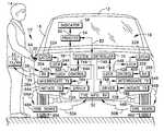
- FIG. 1is an illustration of an authorized person and a vehicle with a function block diagram of an associated vehicle communication system in accordance with the present invention
- FIG. 2is schematic diagram of a portion of the communication system of FIG. 1;
- FIG. 3is a function block diagram of a portable identification unit of the system of FIG. 1;
- FIG. 4is a function block diagram of a tire condition sensor unit of the system of FIG. 1 .
- a communication system 10in accordance with the present invention, along with an associated vehicle 12 and an authorized person 14 are shown in FIG. 1 .
- the communication system 10provides for vehicle entry control and tire condition information conveyance.
- the communication system 10includes components that comprise an interrogation arrangement for permitting access for the authorized person 14 through a vehicle entranceway, and the system includes components that comprise an arrangement for conveying information regarding a sensed tire condition to apprise a vehicle operator (e.g., the person 14 ) of the sensed condition.
- the illustrated example of the communication system 10includes other components that permit access through other vehicle entranceway(s) and that convey other sensed tire condition(s).
- identical componentsare identified with identical reference numerals, but with different alphabetic suffixes. It is to be understood that provided descriptions are generally applicable to the identical components.
- the illustrated example that permits access through plural vehicle entranceways and that conveys plural sensed tire conditionsis not to be construed as limiting the scope of the present invention.
- the vehicle 12includes an interior 16 that is enclosed by at least one access door 18 .
- the door 18is movable and has a handle 20 that is manually actuatable by the person 14 to cause actuation of a latch mechanism 22 A.
- Latch mechanism actuationreleases the door 18 to open, such that the person 14 may gain entrance into the interior 16 of the vehicle 12 .
- the door 18is an entrance cover that closes an entranceway into the vehicle interior 16 .
- a lock mechanism 24 Amaintains the latch mechanism 22 A in a latched condition and prevents opening of the door 18 .
- the latch mechanism 22 A and lock mechanism 24 Amay have any construction type and configuration.
- the above-mentioned interrogation arrangement of the communication system 10includes components 28 A and 30 A located at the vehicle 12 and an identification transceiver 32 located on the authorized person 14 .
- the components 28 A and 30 A, at the vehicle 12 , and the identification transceiver 32engage in an interrogation communication exchange for the identification of the bearer of the identification transceiver as the authorized person 14 who is properly permitted to gain access to the vehicle interior 16 .
- the components 28 A and 30 A at the vehicle 12include an interrogation transmit component 28 A (e.g., an antenna) that emits an interrogation signal 36 intended for reception by the identification transceiver 32 , and an interrogation receive component 30 A (e.g., an antenna) that receives a response signal 38 from the identification transceiver.
- the interrogation transmit component 28 A and the interrogation receive component 30 Aare located in close proximity to the door 18 .
- the identification transceiver 32may take the form of a button or tag that the authorized person 14 carries in their pocket or purse, or secured to their key chain.
- the identification transceiver 32receives the interrogation signal 36 , and in response to reception of the interrogation signal, emits the response signal 38 .
- the response signal 38conveys an appropriate security code, which identifies the bearer of the identification transceiver 32 as the person authorized to enter the vehicle 12 .
- the interrogation receive component 30 Ais operatively connected 40 A a lock control component 42 A.
- the lock control component 42 Ais, in turn, operatively connected 44 A to the lock mechanism 24 A, and controls operation of the lock mechanism.
- the lock control component 42 Aprovides a signal to the lock mechanism 24 A that causes actuation to an unlock condition.
- the authorized person 14can gain entry to the interior 16 of the vehicle 12 without manually operating any unlock device, such as manually turning a key, manually operating a hand-held transmitter, or manually entering a code on a touch pad at the vehicle, or the like.
- the interrogation sequenceis initiated via any suitable manner.
- the interrogation sequencemay result from timing, proximity sensing, touching the handle, pushing a switch, etc.
- the vehiclehas a plurality of inflatable tires (e.g., 46 A and 46 B).
- a plurality of inflatable tirese.g., 46 A and 46 B.
- two ground-engaging tires 46 A and 46 Bare shown.
- the vehicle 12may have any number of tires.
- the vehicle 12includes five tires, with four engaging the ground and one stored as a spare.
- the communication system 10provides tire condition information to an operator (e.g., the person 14 ).
- the communication system 10includes a plurality of tire condition sensor units (e.g., 48 A and 48 B) for sensing one or more tire conditions at the vehicle tires (e.g., 46 A and 46 B).
- the number of tire condition sensor unitsis equal to the number of tires provided on the vehicle 12 .
- the sensor unitis associated with the tire 46 A in any suitable manner.
- the sensor unit 48 Ais mounted within the tire 46 A.
- the sensor unittransmits a signal 50 A that conveys one or more sensed conditions along with an identification to a vehicle-based receive component 52 (e.g., an antenna).
- a vehicle-based receive component 52e.g., an antenna
- a process component 54is operatively connected 56 to the receive component 52 , and in turn, an indicator device 58 is operatively connected 60 to the process component.
- the conveyed sensed tire informationis processed and the information is provided to the vehicle operator (e.g., the person 14 ) via the indicator device 58 .
- the indicator device 58is a visual display that is located on an instrument panel of the vehicle 12 . Accordingly, the vehicle operator (e.g., the person 14 ) is apprised of the sensed condition(s) at the tire 46 A.
- the sensed conditionmay be any condition at the tire 46 A.
- the sensed conditionmay be inflation pressure of the tire 46 A, temperature of the tire, motion of the tire, or even a diagnostic condition of the tire condition sensor unit 48 A itself.
- the receive component 52is a single component that receives signals (e.g., 50 A and 50 B) from a plurality of tire condition sensor units (e.g., 48 A and 48 B).
- the communication system 10includes a plurality of initiate transmit components (e.g., 64 A and 64 B).
- Each initiate transmit component(e.g., 64 A) is controllably energized to output an initiation signal (e.g., 66 A) that causes an associated one (e.g., 48 A) of the tire condition sensor units to respond with its signal (e.g., 50 A).
- each initiation signal(e.g., 66 A) is a request that causes a signal response from the associated tire condition sensor unit (e.g., 48 A).
- Each initiate transmit component(e.g., 64 A) is mounted on the vehicle 12 at a location adjacent to a respective one (e.g., 46 A) of the vehicle tires.
- each initiate transmit component(e.g., 64 A) is mounted within the wheel well associated with the respective tire (e.g., 46 A).
- the initiate transmit componente.g., 64 A
- the tire condition sensor unite.g., 48 A
- the response signale.g., 50 A
- a controller 70 of the communication system 10controls all of the communication originating from the vehicle 12 . Specifically, the system controller 70 controls the output of the interrogation signal 36 and controls the output of the initiation signal (e.g., 66 A).
- the actual output of the signals 36 and 66 Ais accomplished via the use of one or more additional shared components (e.g., 72 A).
- shared componentsis directed to the point that interrogation communication for keyless vehicle entry and tire condition monitoring communication has, in the past, been accomplished via separate systems with separate components.
- a driver component 72 Ais operative connected 74 A to the system controller 70 .
- the driver 72 Ais also operatively connected 76 A to at least one interrogation transmit component (e.g., 28 A) and operatively connected 78 A to at least one initiate transmit component (e.g., 64 A).
- the system controller 70is operatively connected 82 to the process component 54 and is operatively connected 84 A to the respective lock control component 42 A.
- the system controller 70controls the driver 72 to stimulate the connected interrogation transmit component 28 A.
- the initiation signal 66 Ais to be output, the system controller 70 controls the driver 72 to stimulate the connected initiate transmit component 64 A.
- the driver 72is a shared component for the two types of communication. Further, the system controller 70 , itself, is a shared component.
- FIG. 2illustrates a portion of an example embodiment of the communication system 10 with the shared component (e.g., the driver 72 ), in accordance with the present invention.
- the exampleis applicable to both the portion of the system 10 identified with a suffix “A” and the portion identified with the suffix “B.” As such, FIG. 2 is presented without alphabetic suffixes.
- the interrogation signal 36 and the initiation signal 66are both low-frequency, magnetic induction signals.
- the exampleshows a single identification transceiver 32 , a single tire sensor unit 48 , and the vehicle components associated with the interrogation communication and the initiation communication.
- the driver 72is a circuit arrangement that is shown in the form of an amplifier operatively connected to the system controller 70 .
- Signals output from the driver 72are pulsed signals that have either a first frequency or a second, different frequency.
- each output signalhas a square waveform.
- the interrogation transmit component 28is connected to an output of the driver 72 and the initiate transmit component 64 is connected to the output of the driver.
- the interrogation transmit component 28 and the initiate transmit component 64are connected in parallel between the driver 72 and electrical ground. Accordingly, the stimulus of the signal output from the driver 72 is applied to interrogation transmit component 28 and the initiate transmit component 64 .
- the interrogation transmit component 28includes a first antenna 90 that is stimulated to output the interrogation signal 36 . Also, the interrogation transmit component 28 includes a first resistor 92 and a first capacitor 94 connected in series with the first antenna 90 between the driver 72 and ground. Thus, the first resistor 92 , the first capacitor 94 , and the first antenna 90 , which has an inductance, comprise a first RLC circuit that is the interrogation transmit component 28 .
- the first circuit(interrogation transmit component 28 ) has a relatively high gain or “Q” associated with the first frequency, and relatively little or no gain associated with the second frequency.
- the initiate transmit component 64has a group of elements similar to the components of the interrogation transmit component 28 .
- the initiate transmit component 64includes a second antenna 100 , which is stimulated to output the initiation signal 66 , a second resistor 102 , and a second capacitor 104 .
- the second antenna 100 , the second resistor 102 , and the second capacitor 104are connected in series between the driver 72 and ground.
- the second antenna 100has an inductance.
- the initiate transmit component 64is a second RLC circuit.
- One or more of the resistance, capacitance, and/or the inductance values of the initiate transmit component 64are different than the respective resistance, capacitance, and/or the inductance values of the interrogate transmit component 28 (the first circuit).
- the initiate transmit component 64(the second circuit) has a relatively high gain or “Q” associated with the second frequency, and relatively little or no gain associated with the first frequency.
- first and second frequency signals that are output from the driver 72are applied to both the interrogation transmit component 28 (the first circuit) and the initiate transmit component 64 (the second circuit).
- a stimulation signal from the driver 72 that has the frequency associated with the high gain of a circuitwill cause that circuit to transmit a signal of appreciable strength.
- a stimulation signal at the frequency that is associated with little or no gaindoes not result in a transmitted signal that results in completion of the associated function. Accordingly, only one signal of appreciable strength is sent despite the “sharing” of the driver 72 .
- the driver 72when the driver 72 outputs a signal at the first frequency, the first antenna 90 of the interrogation transmit component 28 is sufficiently excited to transmit the interrogation signal 36 , but the second antenna 100 of the initiate transmit component 64 is not sufficiently excited to transmit any appreciable signal.
- the interrogation signalis associated with the first frequency.
- the antenna 100 of the initiate transmit component 64is sufficiently excited to transmit the initiation signal 66 , but the antenna 90 of the interrogation transmit component 28 is not sufficiently excited to transmit any appreciable signal.
- the initiation signal 66is associated with the second frequency.
- the interrogation signal 36 and the initiation signal 66are within a range of relatively low frequencies.
- the interrogation signal 36 and the initiation signal 66are preferably provided in the form of magnetic field or magnetic induction signals (e.g., a first frequency at 125 kHz and a second frequency at 250 kHz).
- the antennas 90 and 100are magnetic field induction coils.
- the identification transceiver 32 and the tire sensor unit 48each have structure (e.g., antenna) that is appropriate to receive the respective low frequency signal.
- the systemcould be configured differently such that the interrogation signal 36 and the initiation signal 66 are within a different range of frequencies (e.g., the UHF portion of the radio frequency range).
- FIG. 3schematically illustrates one example of the identification transceiver 32 that is compatible with the example of the components shown in FIG. 2 .
- the identification transceiver 32does not include a battery energy source. Energy is transferred to the identification transceiver 32 via the induction coupling.
- An antenna 110e.g., a coil antenna
- the combiner 114is connected 116 to receive circuitry 118 .
- the receive circuitry 118is connected 120 to a controller 122 and is connected 124 to an energy storage device 126 (e.g., a capacitor).
- the output of the antenna 110is provided, via the combiner 114 , to the receive circuitry 118 .
- the interrogation request messageis provided by the EM receive circuitry 118 to the controller 122 .
- Energy that is derived from the interrogation signal 36is supplied to the energy storage device 126 from the receive circuitry 118 .
- the energy storage device 126is connected 128 to the controller 122 and also to transmit circuitry 130 .
- the controller 122accesses a memory 132 that is connected 134 to the controller to retrieve a security code.
- the controller 122which is connected 136 to the transmit circuitry 130 , then provides a response message to the transmit circuitry 130 .
- the transmit circuitry 130is operatively connected 138 to the combiner 114 .
- the transmit circuitry 130conveys an electrical stimulus signal to the antenna 110 via the combiner 114 . In response to the stimulus, the antenna 110 outputs the response signal 38 that conveys the security code, etc.
- the identification transceiver 32 and the receive component 30 Amay be configured differently such that the response signal 38 A is a different type (e.g., within the UHF portion of the radio frequency range). If the identification transceiver 32 is configured differently, it may have increased similarities to the tire condition sensor unit 48 of the example of FIG. 4 .
- FIG. 4schematically illustrates one example of the tire condition sensor unit 48 .
- the exampleis applicable to all of the tire condition sensor units (e.g., 48 A and 48 B). Accordingly, FIG. 4 is presented without alphabetic suffixes.
- a low frequency reception antenna 148is operatively connected 150 to a low frequency signal detector 152 .
- a controller 154is operatively connected 156 to the signal detector 152 .
- the controller 154receives sensory information from one or more sensors 158 that are operatively connected 160 to the controller 154 .
- the controller 154also receives an identification from an identification memory 162 that is operatively connected 164 to the controller 154 .
- the controller 154is further operatively connected 166 to transmit circuitry 168 .
- the communication system 10is designed to operate with the response signal 50 A in the UHF portion of the radio frequency range.
- a message packet that contains the sensory information and the identificationis assembled by the controller 154 and provided to the transmit circuitry 168 .
- the transmit circuitry 168provides an electrical stimulus signal, via a connection 170 , to an antenna 172 that causes the antenna to output the response signal 50 A that conveys the sensory information and the identification.
- the tire condition sensor unit 48is powered either via a battery (not shown), or derives energy from the initiation signal 66 .
- the tire condition sensor unit 48 A and the receive component 52may be configured differently such that the signal 50 A is a different type (e.g., within the low frequency range). Further, if the identification transceiver 32 and/or the tire condition sensor unit 48 A are configured such that the signals 38 and 50 A have the same format (e.g., both at the same frequency within the UHF portion of the radio frequency range), the receive component 30 A and the receive component 52 may be combined as a single unit. This provides for additional sharing of components.
- Another example of a communication system in accordance with the present inventionprovides an interrogation signal and an initiation signal via a common driver and a common transmit component (i.e., a common antenna) mounted in a vehicle.
- the single transmit component(antenna) is stimulated to emit the interrogation signal at the first frequency at a first point in time, and is stimulated to emit the initiation signal at the second frequency at a second point in time.
- Such frequenciesmay be 125 and 250 kHz, as previously discussed.
- the identification transceiver(or receiver) is responsive to the first frequency and not the second frequency, and the tire condition sensor unit is responsive to the second frequency and not the first frequency. Thus, each is not affected by the other frequency signal.
Landscapes
- Engineering & Computer Science (AREA)
- Mechanical Engineering (AREA)
- Arrangements For Transmission Of Measured Signals (AREA)
- Lock And Its Accessories (AREA)
Abstract
Description
Claims (12)
Priority Applications (3)
| Application Number | Priority Date | Filing Date | Title |
|---|---|---|---|
| US09/727,251US6597284B2 (en) | 2000-11-29 | 2000-11-29 | Vehicle communication for tire sensor initiation and vehicle keyless entry via a shared resource |
| DE60108342TDE60108342T2 (en) | 2000-11-29 | 2001-11-12 | Vehicle communication system for tire pressure sensor activation and vehicle keyless entry system through a shared source |
| EP01126889AEP1211104B1 (en) | 2000-11-29 | 2001-11-12 | Vehicle communication for tire sensor initiation and vehicle keyless entry via a shared resource |
Applications Claiming Priority (1)
| Application Number | Priority Date | Filing Date | Title |
|---|---|---|---|
| US09/727,251US6597284B2 (en) | 2000-11-29 | 2000-11-29 | Vehicle communication for tire sensor initiation and vehicle keyless entry via a shared resource |
Publications (2)
| Publication Number | Publication Date |
|---|---|
| US20020063623A1 US20020063623A1 (en) | 2002-05-30 |
| US6597284B2true US6597284B2 (en) | 2003-07-22 |
Family
ID=24921918
Family Applications (1)
| Application Number | Title | Priority Date | Filing Date |
|---|---|---|---|
| US09/727,251Expired - LifetimeUS6597284B2 (en) | 2000-11-29 | 2000-11-29 | Vehicle communication for tire sensor initiation and vehicle keyless entry via a shared resource |
Country Status (3)
| Country | Link |
|---|---|
| US (1) | US6597284B2 (en) |
| EP (1) | EP1211104B1 (en) |
| DE (1) | DE60108342T2 (en) |
Cited By (23)
| Publication number | Priority date | Publication date | Assignee | Title |
|---|---|---|---|---|
| US20020008615A1 (en)* | 1999-11-30 | 2002-01-24 | Patric Heide | Anti-theft protection system for a motor vehicle, and a method for operating an anti-theft protection system |
| US20030016140A1 (en)* | 2000-03-09 | 2003-01-23 | Bernard Brillon Alain Marc | Transmitting and receiving method, in particular for detection of an ID transmitter |
| US20030095031A1 (en)* | 2001-10-16 | 2003-05-22 | Mario Haselsteiner | Antitheft protection system, method for operating an antitheft protection system and components of an antifheft protection system |
| US20040095233A1 (en)* | 2002-11-14 | 2004-05-20 | Trw Inc. | Method and apparatus for associating tires with tire locations of a vehicle |
| US20040095232A1 (en)* | 2002-11-18 | 2004-05-20 | Pacific Industrial Co., Ltd | Transmitting method of transmitter and processing method of receiver |
| US20040095231A1 (en)* | 2001-09-05 | 2004-05-20 | Hidemi Ichinose | Tire monitoring system |
| US20040155764A1 (en)* | 2003-02-10 | 2004-08-12 | Honda Motor Co., Ltd. | Tire pressure detection system and a wheel used therein |
| US20050017860A1 (en)* | 2002-07-31 | 2005-01-27 | Hiroyuki Tsuji | ID registration method for tire air pressure sensor, ID registration system, tire air pressure monitoring system, tire air pressure sensor, and smart control system |
| US20050083174A1 (en)* | 2001-12-10 | 2005-04-21 | Akihiko Nakamura | Object sensor and controller |
| US20050280501A1 (en)* | 2004-06-21 | 2005-12-22 | Honeywell International, Inc. | Automotive latch and RF system interfacing |
| US20070126561A1 (en)* | 2000-09-08 | 2007-06-07 | Automotive Technologies International, Inc. | Integrated Keyless Entry System and Vehicle Component Monitoring |
| US20070200671A1 (en)* | 2006-02-28 | 2007-08-30 | Kelley Nia L | Methods and apparatuses for remote control of vehicle devices and vehicle lock-out notification |
| US20070273478A1 (en)* | 2006-05-26 | 2007-11-29 | John Phillip Chevalier | Automotive latch and RF system interfacing |
| US20080001706A1 (en)* | 2006-06-19 | 2008-01-03 | Kaba Iico Inc. | Low power detection method for proximity lock |
| US20090009303A1 (en)* | 2007-07-05 | 2009-01-08 | Aisin Seiki Kabushiki Kaisha | Communication system for vehicle |
| US20110304451A1 (en)* | 2010-06-15 | 2011-12-15 | Honda Motor Co., Ltd. | Localization of tire for tpms and smart entry system |
| US8151127B2 (en) | 2000-07-26 | 2012-04-03 | Bridgestone Americas Tire Operations, Llc | System for conserving battery life in a battery operated device |
| US8266465B2 (en) | 2000-07-26 | 2012-09-11 | Bridgestone Americas Tire Operation, LLC | System for conserving battery life in a battery operated device |
| US20130021149A1 (en)* | 2011-07-19 | 2013-01-24 | Kabushiki Kaisha Tokai Rika Denki Seisakusho | Multifunction receiver |
| US8718868B2 (en) | 2011-06-30 | 2014-05-06 | GM Global Technology Operations LLC | Vehicle using tire temperature to adjust active chassis systems |
| US8896418B2 (en) | 2011-09-16 | 2014-11-25 | Honda Motor Co., Ltd. | Method to increase accuracy of locating unit in wireless vehicle system |
| US20150218857A1 (en)* | 2014-02-04 | 2015-08-06 | Honda Motor Co., Ltd. | Vehicular door device |
| US11381337B2 (en)* | 2019-08-06 | 2022-07-05 | Firstech, LLC | Vehicle access with selective jamming radio signal |
Families Citing this family (28)
| Publication number | Priority date | Publication date | Assignee | Title |
|---|---|---|---|---|
| US6668636B2 (en) | 2002-03-01 | 2003-12-30 | Lear Corporation | System and method for tire pressure monitoring including tire location recognition |
| US7154414B2 (en) | 2002-03-01 | 2006-12-26 | Lear Corporation | System and method for remote tire pressure monitoring |
| US6788193B2 (en) | 2002-03-01 | 2004-09-07 | Lear Corporation | System and method for tire pressure monitoring providing automatic tire location recognition |
| US6829924B2 (en) | 2002-03-01 | 2004-12-14 | Lear Corporation | Tire pressure monitoring system with low frequency initiation approach |
| US6933898B2 (en) | 2002-03-01 | 2005-08-23 | Lear Corporation | Antenna for tire pressure monitoring wheel electronic device |
| US6876265B2 (en) | 2002-03-01 | 2005-04-05 | Lear Corporation | System and method for using a saw based RF transmitter for AM modulated transmission in a TPM |
| US6725712B1 (en) | 2002-03-01 | 2004-04-27 | Lear Corporation | System and method for tire pressure monitoring with automatic tire location recognition |
| US6647773B2 (en)* | 2002-03-01 | 2003-11-18 | Lear Corporation | System and method for integrated tire pressure monitoring and passive entry |
| US6838985B2 (en) | 2002-03-25 | 2005-01-04 | Lear Corporation | System and method for remote tire pressure monitoring with low frequency initiation |
| DE10235127A1 (en)* | 2002-08-01 | 2004-02-19 | Beru Ag | Device for monitoring and wireless signaling of a pressure or a change in pressure in pneumatic tires |
| JP4007905B2 (en)* | 2002-12-10 | 2007-11-14 | アルプス電気株式会社 | Passive keyless entry device for monitoring tire pressure with two-way communication |
| DE10300778A1 (en)* | 2003-01-11 | 2004-07-22 | Leopold Kostal Gmbh & Co Kg | Tire pressure monitoring device for a motor vehicle |
| US20050093686A1 (en) | 2003-10-30 | 2005-05-05 | Lear Corporation | Tire pressure monitoring sensor diagnosis via vehicle antitheft and entry system |
| DE102004021774A1 (en) | 2004-04-30 | 2005-11-24 | Texas Instruments Deutschland Gmbh | Tire pressure monitoring system |
| FR2863204A1 (en)* | 2004-08-10 | 2005-06-10 | Siemens Vdo Automotive | Motor vehicle wheels tracking method, involves transmitting non-coded signals for wheel unit actuation or hands free function, by antennas, where transmitters and antennas are controlled by control device connected to central unit |
| DE102006012535A1 (en) | 2005-04-01 | 2006-10-19 | Continental Teves Ag & Co. Ohg | Tire pressure monitoring system and method of assigning tire modules in a tire air pressure monitoring system |
| US7292137B2 (en)* | 2005-05-13 | 2007-11-06 | Lear Corporation | Energy efficient passive entry system |
| US7515039B2 (en)* | 2006-06-05 | 2009-04-07 | Kavlico Corporation | Method and apparatus for tire pressure monitoring |
| US8091280B2 (en)* | 2007-06-01 | 2012-01-10 | GM Global Technology Operations LLC | Arms full vehicle closure activation apparatus and method |
| US20090066496A1 (en)* | 2007-09-11 | 2009-03-12 | Lear Corporation | Low frequency receiver for a tire pressure monitor system |
| JP5244353B2 (en)* | 2007-09-14 | 2013-07-24 | 株式会社ブリヂストン | Tire quantity management system |
| JP5086219B2 (en)* | 2008-09-30 | 2012-11-28 | 本田技研工業株式会社 | Trunk locking device for vehicle |
| JP2010149537A (en)* | 2008-12-23 | 2010-07-08 | Autonetworks Technologies Ltd | Control apparatus, control method, and computer program |
| DE102011121775B3 (en) | 2011-12-21 | 2013-01-31 | Brose Fahrzeugteile Gmbh & Co. Kg, Hallstadt | Control system for controlling e.g. motorized side door of motor car, has distance sensors with dummy portions such that sensors comprise no sensitivity or smaller sensitivity compared to region of each sensor adjacent to dummy portions |
| JP6414452B2 (en)* | 2014-12-05 | 2018-10-31 | 株式会社オートネットワーク技術研究所 | In-vehicle communication system and in-vehicle device |
| DE102015112589A1 (en) | 2015-07-31 | 2017-02-02 | Brose Fahrzeugteile Gmbh & Co. Kommanditgesellschaft, Bamberg | Control system for a motor-adjustable loading space device of a motor vehicle |
| US10857844B2 (en)* | 2016-01-15 | 2020-12-08 | Infineon Technologies Ag | Tire parameter monitoring system |
| DE102016108702A1 (en)* | 2016-05-11 | 2017-11-16 | Brose Fahrzeugteile Gmbh & Co. Kg, Bamberg | Method for controlling a motor-driven closure element arrangement of a motor vehicle |
Citations (14)
| Publication number | Priority date | Publication date | Assignee | Title |
|---|---|---|---|---|
| US4811013A (en) | 1985-10-28 | 1989-03-07 | Kokusan Kinzoku Kogyo Kabushiki Kaisha | Vehicle use-locking and unlocking system |
| US4942393A (en) | 1988-05-27 | 1990-07-17 | Lectron Products, Inc. | Passive keyless entry system |
| US5301553A (en) | 1989-12-20 | 1994-04-12 | Tjs Development Corporation | Apparatus for remote sensing and receiving |
| US5463374A (en) | 1994-03-10 | 1995-10-31 | Delco Electronics Corporation | Method and apparatus for tire pressure monitoring and for shared keyless entry control |
| US5552641A (en) | 1993-09-02 | 1996-09-03 | Siemens Aktiengesellschaft | Remote-control access control device and method for operating the same |
| US5552789A (en)* | 1994-02-14 | 1996-09-03 | Texas Instruments Deutschland Gmbh | Integrated vehicle communications system |
| US5661651A (en)* | 1995-03-31 | 1997-08-26 | Prince Corporation | Wireless vehicle parameter monitoring system |
| US5682135A (en) | 1995-05-04 | 1997-10-28 | Kiekert Ag | Motor vehicle security system |
| US5774047A (en) | 1996-04-12 | 1998-06-30 | Hensel, Iv; Frederick William | Tire pressure sensing system including improved switch and location indicator |
| US5790016A (en) | 1997-01-15 | 1998-08-04 | Algonquin Scientific, Llc | Tire pressure sensing system |
| US5838229A (en)* | 1995-07-18 | 1998-11-17 | Schrader-Bridgeport International, Inc. | Remote tire pressure monitoring system employing coded tire identification and radio frequency transmission and enabling recalibration upon tire rotation or replacement |
| US5880363A (en) | 1996-08-09 | 1999-03-09 | Temic Telefunken Microelectronic Gmbh | Process for checking air pressure in vehicle wheel tires |
| US5924055A (en) | 1994-11-14 | 1999-07-13 | The Yokohama Rubber Co., Ltd. | Vehicle tire air pressure monitor |
| US6259362B1 (en)* | 1999-09-21 | 2001-07-10 | Trw Inc. | System for conveying vehicle status information upon exit from a vehicle |
- 2000
- 2000-11-29USUS09/727,251patent/US6597284B2/ennot_activeExpired - Lifetime
- 2001
- 2001-11-12EPEP01126889Apatent/EP1211104B1/ennot_activeExpired - Lifetime
- 2001-11-12DEDE60108342Tpatent/DE60108342T2/ennot_activeExpired - Lifetime
Patent Citations (15)
| Publication number | Priority date | Publication date | Assignee | Title |
|---|---|---|---|---|
| US4811013A (en) | 1985-10-28 | 1989-03-07 | Kokusan Kinzoku Kogyo Kabushiki Kaisha | Vehicle use-locking and unlocking system |
| US4942393A (en) | 1988-05-27 | 1990-07-17 | Lectron Products, Inc. | Passive keyless entry system |
| US5319364A (en) | 1988-05-27 | 1994-06-07 | Lectron Products, Inc. | Passive keyless entry system |
| US5301553A (en) | 1989-12-20 | 1994-04-12 | Tjs Development Corporation | Apparatus for remote sensing and receiving |
| US5552641A (en) | 1993-09-02 | 1996-09-03 | Siemens Aktiengesellschaft | Remote-control access control device and method for operating the same |
| US5552789A (en)* | 1994-02-14 | 1996-09-03 | Texas Instruments Deutschland Gmbh | Integrated vehicle communications system |
| US5463374A (en) | 1994-03-10 | 1995-10-31 | Delco Electronics Corporation | Method and apparatus for tire pressure monitoring and for shared keyless entry control |
| US5924055A (en) | 1994-11-14 | 1999-07-13 | The Yokohama Rubber Co., Ltd. | Vehicle tire air pressure monitor |
| US5661651A (en)* | 1995-03-31 | 1997-08-26 | Prince Corporation | Wireless vehicle parameter monitoring system |
| US5682135A (en) | 1995-05-04 | 1997-10-28 | Kiekert Ag | Motor vehicle security system |
| US5838229A (en)* | 1995-07-18 | 1998-11-17 | Schrader-Bridgeport International, Inc. | Remote tire pressure monitoring system employing coded tire identification and radio frequency transmission and enabling recalibration upon tire rotation or replacement |
| US5774047A (en) | 1996-04-12 | 1998-06-30 | Hensel, Iv; Frederick William | Tire pressure sensing system including improved switch and location indicator |
| US5880363A (en) | 1996-08-09 | 1999-03-09 | Temic Telefunken Microelectronic Gmbh | Process for checking air pressure in vehicle wheel tires |
| US5790016A (en) | 1997-01-15 | 1998-08-04 | Algonquin Scientific, Llc | Tire pressure sensing system |
| US6259362B1 (en)* | 1999-09-21 | 2001-07-10 | Trw Inc. | System for conveying vehicle status information upon exit from a vehicle |
Non-Patent Citations (5)
| Title |
|---|
| An internet press release form Siemens Automotive dated Jan. 24, 2001. |
| Brochure from AVCO Precision Products Division, entitled "TYRECHEK Low Tire Pressure Monitoring & Warning System", and having a lithography ID 473. |
| Pending U.S. DeZorzi patent application Ser. No. 09/711,588, filed Nov. 14, 2000 entitled Tire Condition Sensor Communication with Duty-Cycled Amplified Tire-Side Reception. |
| Pending U.S. Juzswik patent application Ser. No. 09/687,709, filed Oct. 13, 2000 entitled Vehicle-Controlled Tire Condition Sensor Communication Utilizing Fixed Tire Identification. |
| Pending U.S. Steiner patent application Ser. No. 09/300,415, filed Apr. 27, 1999 entitled System and Method for Automatic Vehicle Unlock Initiated via Beam Interruption. |
Cited By (41)
| Publication number | Priority date | Publication date | Assignee | Title |
|---|---|---|---|---|
| US20020008615A1 (en)* | 1999-11-30 | 2002-01-24 | Patric Heide | Anti-theft protection system for a motor vehicle, and a method for operating an anti-theft protection system |
| US20030016140A1 (en)* | 2000-03-09 | 2003-01-23 | Bernard Brillon Alain Marc | Transmitting and receiving method, in particular for detection of an ID transmitter |
| US7023321B2 (en) | 2000-03-09 | 2006-04-04 | Siemens Aktiengesellschaft | Transmitting and receiving method, especially for detecting an ID transmitter |
| US8266465B2 (en) | 2000-07-26 | 2012-09-11 | Bridgestone Americas Tire Operation, LLC | System for conserving battery life in a battery operated device |
| US8151127B2 (en) | 2000-07-26 | 2012-04-03 | Bridgestone Americas Tire Operations, Llc | System for conserving battery life in a battery operated device |
| US20070126561A1 (en)* | 2000-09-08 | 2007-06-07 | Automotive Technologies International, Inc. | Integrated Keyless Entry System and Vehicle Component Monitoring |
| US7019628B2 (en)* | 2001-09-05 | 2006-03-28 | Honda Giken Kogyo Kabushiki Kaisha | Tire monitoring and keyless entry system |
| US20040095231A1 (en)* | 2001-09-05 | 2004-05-20 | Hidemi Ichinose | Tire monitoring system |
| US20030095031A1 (en)* | 2001-10-16 | 2003-05-22 | Mario Haselsteiner | Antitheft protection system, method for operating an antitheft protection system and components of an antifheft protection system |
| US7061397B2 (en)* | 2001-10-16 | 2006-06-13 | Siemens Aktiengesellschaft | Antitheft protection system, method for operating an antitheft protection system and components of an antitheft protection system |
| US7283034B2 (en)* | 2001-12-10 | 2007-10-16 | Omron Corporation | Object sensor and controller |
| US20050083174A1 (en)* | 2001-12-10 | 2005-04-21 | Akihiko Nakamura | Object sensor and controller |
| US6967570B2 (en)* | 2002-07-31 | 2005-11-22 | Denso Corporation | ID registration method for tire air pressure sensor, ID registration system, tire air pressure monitoring system, tire air pressure sensor, and smart control system |
| US20050017860A1 (en)* | 2002-07-31 | 2005-01-27 | Hiroyuki Tsuji | ID registration method for tire air pressure sensor, ID registration system, tire air pressure monitoring system, tire air pressure sensor, and smart control system |
| US6879252B2 (en)* | 2002-11-14 | 2005-04-12 | Trw Inc. | Method and apparatus for associating tires with tire locations of a vehicle |
| US20040095233A1 (en)* | 2002-11-14 | 2004-05-20 | Trw Inc. | Method and apparatus for associating tires with tire locations of a vehicle |
| US20040095232A1 (en)* | 2002-11-18 | 2004-05-20 | Pacific Industrial Co., Ltd | Transmitting method of transmitter and processing method of receiver |
| US7091840B2 (en)* | 2003-02-10 | 2006-08-15 | Honda Motor Co., Ltd. | Tire pressure detection system and a wheel used therein |
| US20040155764A1 (en)* | 2003-02-10 | 2004-08-12 | Honda Motor Co., Ltd. | Tire pressure detection system and a wheel used therein |
| US20050280501A1 (en)* | 2004-06-21 | 2005-12-22 | Honeywell International, Inc. | Automotive latch and RF system interfacing |
| US20070200671A1 (en)* | 2006-02-28 | 2007-08-30 | Kelley Nia L | Methods and apparatuses for remote control of vehicle devices and vehicle lock-out notification |
| US7961076B2 (en) | 2006-02-28 | 2011-06-14 | International Business Machines Corporation | Methods and apparatuses for remote control of vehicle devices and vehicle lock-out notification |
| US20070273478A1 (en)* | 2006-05-26 | 2007-11-29 | John Phillip Chevalier | Automotive latch and RF system interfacing |
| US20080001706A1 (en)* | 2006-06-19 | 2008-01-03 | Kaba Iico Inc. | Low power detection method for proximity lock |
| US20090009303A1 (en)* | 2007-07-05 | 2009-01-08 | Aisin Seiki Kabushiki Kaisha | Communication system for vehicle |
| US8120474B2 (en) | 2007-07-05 | 2012-02-21 | Aisin Seiki Kabushiki Kaisha | Communication system for vehicle |
| US8497772B2 (en) | 2010-06-15 | 2013-07-30 | Honda Motor Co., Ltd. | Radio system adjustment with TPMS and smart entry system |
| US8564428B2 (en) | 2010-06-15 | 2013-10-22 | Honda Motor Co., Ltd. | Memorizing location of tires in TPMS and smart entry system |
| US8344869B2 (en)* | 2010-06-15 | 2013-01-01 | Honda Motor Co., Ltd. | Door open detection for use with TPMS and smart entry system |
| US9399376B2 (en) | 2010-06-15 | 2016-07-26 | Honda Motor Co., Ltd. | Recognizing tire sensor location in factory mode for TPMS and smart entry system |
| US8446271B2 (en) | 2010-06-15 | 2013-05-21 | Honda Motor Co., Ltd. | Unique header format for TPMS and SMART entry system |
| US8497771B2 (en)* | 2010-06-15 | 2013-07-30 | Honda Motor Co., Ltd. | Localization of tire for TPMS and smart entry system |
| US20110304450A1 (en)* | 2010-06-15 | 2011-12-15 | Honda Motor Co., Ltd. | Door open detection for use with tpms and smart entry system |
| US20110304451A1 (en)* | 2010-06-15 | 2011-12-15 | Honda Motor Co., Ltd. | Localization of tire for tpms and smart entry system |
| US8686847B2 (en) | 2010-06-15 | 2014-04-01 | Honda Motor Co., Ltd. | Two axis antenna for TPMS sensor |
| US8718868B2 (en) | 2011-06-30 | 2014-05-06 | GM Global Technology Operations LLC | Vehicle using tire temperature to adjust active chassis systems |
| US20130021149A1 (en)* | 2011-07-19 | 2013-01-24 | Kabushiki Kaisha Tokai Rika Denki Seisakusho | Multifunction receiver |
| US8896418B2 (en) | 2011-09-16 | 2014-11-25 | Honda Motor Co., Ltd. | Method to increase accuracy of locating unit in wireless vehicle system |
| US20150218857A1 (en)* | 2014-02-04 | 2015-08-06 | Honda Motor Co., Ltd. | Vehicular door device |
| US9932761B2 (en)* | 2014-02-04 | 2018-04-03 | Honda Motor Co., Ltd. | Vehicular door device |
| US11381337B2 (en)* | 2019-08-06 | 2022-07-05 | Firstech, LLC | Vehicle access with selective jamming radio signal |
Also Published As
| Publication number | Publication date |
|---|---|
| DE60108342T2 (en) | 2005-12-22 |
| EP1211104A3 (en) | 2003-04-09 |
| DE60108342D1 (en) | 2005-02-17 |
| US20020063623A1 (en) | 2002-05-30 |
| EP1211104A2 (en) | 2002-06-05 |
| EP1211104B1 (en) | 2005-01-12 |
Similar Documents
| Publication | Publication Date | Title |
|---|---|---|
| US6597284B2 (en) | Vehicle communication for tire sensor initiation and vehicle keyless entry via a shared resource | |
| US7388466B2 (en) | Integrated passive entry and remote keyless entry system | |
| KR100669599B1 (en) | Vehicle remote control system and tire pressure monitoring system | |
| US7202777B2 (en) | Tire condition monitoring system | |
| US10737659B2 (en) | Protocols for remote vehicle access systems | |
| US6937136B2 (en) | Security system | |
| US7551070B2 (en) | Wireless sensing system | |
| CN103068599B (en) | TPMS and SMART enters system | |
| US9811956B2 (en) | Passive entry system and method for a vehicle | |
| US6647773B2 (en) | System and method for integrated tire pressure monitoring and passive entry | |
| US6211776B1 (en) | Method for initializing an anti-theft system for a motor vehicle | |
| US20020087250A1 (en) | Remote control convenience and information conveyance system associated with a vehicle | |
| US20160267735A1 (en) | Vehicle wireless communication system, vehicle control device, and portable machine | |
| US6871157B2 (en) | Method for automatically locating a motor vehicle wheel and corresponding locating unit | |
| US20090066477A1 (en) | Authentication apparatus | |
| US20060176147A1 (en) | Vehicle security system | |
| US6509825B1 (en) | Integrated circuit device having a self-biased, single pin radio frequency signal input | |
| US9902369B2 (en) | Apparatus and method for dual range detection in a vehicle | |
| EP1614592B1 (en) | Keyless entry device | |
| US7009491B2 (en) | Dual purpose vehicle key fob for training tire pressure sensors | |
| US20100039222A1 (en) | Keyless access system and method for a truck and truck equipped with such a system | |
| US20020022494A1 (en) | Method for interior-space/exterior-space detection of a response transmitter which communicates in wire-free fashion with a base station, and a communications system | |
| US20030076234A1 (en) | Method and system for determining wheel position | |
| US6873247B2 (en) | Combined vehicle immobilizing and steering column control system | |
| US20020149469A1 (en) | Single point failure avoidance for a keyless passive entry and immobilizer system |
Legal Events
| Date | Code | Title | Description |
|---|---|---|---|
| AS | Assignment | Owner name:TRW INC., OHIO Free format text:ASSIGNMENT OF ASSIGNORS INTEREST;ASSIGNOR:JUZSWIK, DAVID LEONARD;REEL/FRAME:011322/0889 Effective date:20001121 | |
| FEPP | Fee payment procedure | Free format text:PAYER NUMBER DE-ASSIGNED (ORIGINAL EVENT CODE: RMPN); ENTITY STATUS OF PATENT OWNER: LARGE ENTITY Free format text:PAYOR NUMBER ASSIGNED (ORIGINAL EVENT CODE: ASPN); ENTITY STATUS OF PATENT OWNER: LARGE ENTITY | |
| AS | Assignment | Owner name:JPMORGAN CHASE BANK, NEW YORK Free format text:THE US GUARANTEE AND COLLATERAL AGREEMENT;ASSIGNOR:TRW AUTOMOTIVE U.S. LLC;REEL/FRAME:014022/0720 Effective date:20030228 | |
| STCF | Information on status: patent grant | Free format text:PATENTED CASE | |
| FPAY | Fee payment | Year of fee payment:4 | |
| FPAY | Fee payment | Year of fee payment:8 | |
| AS | Assignment | Owner name:JPMORGAN CHASE BANK, N.A., AS COLLATERAL AGENT, NE Free format text:SECURITY AGREEMENT;ASSIGNORS:TRW VEHICLE SAFETY SYSTEMS INC.;TRW AUTOMOTIVE U.S. LLC;KELSEY-HAYES COMPANY;REEL/FRAME:029529/0534 Effective date:20120928 | |
| AS | Assignment | Owner name:TRW VEHICLE SAFETY SYSTEMS INC., MICHIGAN Free format text:RELEASE OF SECURITY INTEREST;ASSIGNOR:JPMORGAN CHASE BANK, N.A.;REEL/FRAME:031645/0697 Effective date:20131028 Owner name:TRW INTELLECTUAL PROPERTY CORP., MICHIGAN Free format text:RELEASE OF SECURITY INTEREST;ASSIGNOR:JPMORGAN CHASE BANK, N.A.;REEL/FRAME:031645/0697 Effective date:20131028 Owner name:TRW AUTOMOTIVE U.S. LLC, MICHIGAN Free format text:RELEASE OF SECURITY INTEREST;ASSIGNOR:JPMORGAN CHASE BANK, N.A.;REEL/FRAME:031645/0697 Effective date:20131028 Owner name:KELSEY-HAYES COMPANY, MICHIGAN Free format text:RELEASE OF SECURITY INTEREST;ASSIGNOR:JPMORGAN CHASE BANK, N.A.;REEL/FRAME:031645/0697 Effective date:20131028 | |
| FPAY | Fee payment | Year of fee payment:12 |