US6596008B1 - Method and instruments for percutaneous arthroscopic disc removal, bone biopsy and fixation of the vertebral - Google Patents
Method and instruments for percutaneous arthroscopic disc removal, bone biopsy and fixation of the vertebralDownload PDFInfo
- Publication number
- US6596008B1 US6596008B1US09/711,614US71161400AUS6596008B1US 6596008 B1US6596008 B1US 6596008B1US 71161400 AUS71161400 AUS 71161400AUS 6596008 B1US6596008 B1US 6596008B1
- Authority
- US
- United States
- Prior art keywords
- cannula
- obturator
- disc
- section
- oval cross
- Prior art date
- Legal status (The legal status is an assumption and is not a legal conclusion. Google has not performed a legal analysis and makes no representation as to the accuracy of the status listed.)
- Ceased, expires
Links
- 238000000034methodMethods0.000titleclaimsdescription48
- 238000007470bone biopsyMethods0.000title1
- 238000001356surgical procedureMethods0.000claimsabstractdescription20
- 206010016654FibrosisDiseases0.000claimsdescription9
- 208000003618Intervertebral Disc DisplacementDiseases0.000claimsdescription9
- 206010050296Intervertebral disc protrusionDiseases0.000claimsdescription9
- 230000004761fibrosisEffects0.000claimsdescription9
- 239000000463materialSubstances0.000claimsdescription7
- 238000003780insertionMethods0.000abstractdescription23
- 230000037431insertionEffects0.000abstractdescription23
- 238000013459approachMethods0.000abstractdescription6
- 238000002594fluoroscopyMethods0.000abstractdescription2
- 238000002591computed tomographyMethods0.000description14
- 238000012800visualizationMethods0.000description9
- 210000003195fasciaAnatomy0.000description7
- 238000001574biopsyMethods0.000description6
- 210000001519tissueAnatomy0.000description5
- 241001522301Apogonichthyoides nigripinnisSpecies0.000description4
- 210000000988bone and boneAnatomy0.000description4
- 230000004927fusionEffects0.000description4
- 230000007812deficiencyEffects0.000description3
- 238000005259measurementMethods0.000description3
- 210000003205muscleAnatomy0.000description3
- 238000002271resectionMethods0.000description3
- 238000006073displacement reactionMethods0.000description2
- 239000000835fiberSubstances0.000description2
- 239000012634fragmentSubstances0.000description2
- 238000012986modificationMethods0.000description2
- 230000004048modificationEffects0.000description2
- 238000002360preparation methodMethods0.000description2
- 230000001681protective effectEffects0.000description2
- 239000000523sampleSubstances0.000description2
- 241001269524DuraSpecies0.000description1
- 208000007623LordosisDiseases0.000description1
- 230000002159abnormal effectEffects0.000description1
- 210000001142backAnatomy0.000description1
- 230000001054cortical effectEffects0.000description1
- 230000003247decreasing effectEffects0.000description1
- 238000003745diagnosisMethods0.000description1
- 230000000694effectsEffects0.000description1
- 238000003306harvestingMethods0.000description1
- 230000023597hemostasisEffects0.000description1
- 210000003692iliumAnatomy0.000description1
- 238000005286illuminationMethods0.000description1
- 208000015181infectious diseaseDiseases0.000description1
- 210000003041ligamentAnatomy0.000description1
- 230000013011matingEffects0.000description1
- 210000005036nerveAnatomy0.000description1
- 230000001537neural effectEffects0.000description1
- 206010033675panniculitisDiseases0.000description1
- 230000002093peripheral effectEffects0.000description1
- 238000011084recoveryMethods0.000description1
- 238000010079rubber tappingMethods0.000description1
- 210000003491skinAnatomy0.000description1
- 230000006641stabilisationEffects0.000description1
- 238000011105stabilizationMethods0.000description1
- 210000004304subcutaneous tissueAnatomy0.000description1
Images


Classifications
- A—HUMAN NECESSITIES
- A61—MEDICAL OR VETERINARY SCIENCE; HYGIENE
- A61B—DIAGNOSIS; SURGERY; IDENTIFICATION
- A61B17/00—Surgical instruments, devices or methods
- A61B17/56—Surgical instruments or methods for treatment of bones or joints; Devices specially adapted therefor
- A61B17/58—Surgical instruments or methods for treatment of bones or joints; Devices specially adapted therefor for osteosynthesis, e.g. bone plates, screws or setting implements
- A61B17/68—Internal fixation devices, including fasteners and spinal fixators, even if a part thereof projects from the skin
- A61B17/70—Spinal positioners or stabilisers, e.g. stabilisers comprising fluid filler in an implant
- A61B17/7001—Screws or hooks combined with longitudinal elements which do not contact vertebrae
- A61B17/7002—Longitudinal elements, e.g. rods
- A61B17/701—Longitudinal elements with a non-circular, e.g. rectangular, cross-section
- A—HUMAN NECESSITIES
- A61—MEDICAL OR VETERINARY SCIENCE; HYGIENE
- A61B—DIAGNOSIS; SURGERY; IDENTIFICATION
- A61B17/00—Surgical instruments, devices or methods
- A61B17/16—Instruments for performing osteoclasis; Drills or chisels for bones; Trepans
- A61B17/17—Guides or aligning means for drills, mills, pins or wires
- A61B17/1739—Guides or aligning means for drills, mills, pins or wires specially adapted for particular parts of the body
- A61B17/1757—Guides or aligning means for drills, mills, pins or wires specially adapted for particular parts of the body for the spine
- A—HUMAN NECESSITIES
- A61—MEDICAL OR VETERINARY SCIENCE; HYGIENE
- A61B—DIAGNOSIS; SURGERY; IDENTIFICATION
- A61B17/00—Surgical instruments, devices or methods
- A61B17/56—Surgical instruments or methods for treatment of bones or joints; Devices specially adapted therefor
- A61B17/58—Surgical instruments or methods for treatment of bones or joints; Devices specially adapted therefor for osteosynthesis, e.g. bone plates, screws or setting implements
- A61B17/68—Internal fixation devices, including fasteners and spinal fixators, even if a part thereof projects from the skin
- A61B17/70—Spinal positioners or stabilisers, e.g. stabilisers comprising fluid filler in an implant
- A61B17/7001—Screws or hooks combined with longitudinal elements which do not contact vertebrae
- A61B17/7002—Longitudinal elements, e.g. rods
- A61B17/7004—Longitudinal elements, e.g. rods with a cross-section which varies along its length
- A61B17/7007—Parts of the longitudinal elements, e.g. their ends, being specially adapted to fit around the screw or hook heads
- A—HUMAN NECESSITIES
- A61—MEDICAL OR VETERINARY SCIENCE; HYGIENE
- A61B—DIAGNOSIS; SURGERY; IDENTIFICATION
- A61B17/00—Surgical instruments, devices or methods
- A61B17/16—Instruments for performing osteoclasis; Drills or chisels for bones; Trepans
- A61B17/17—Guides or aligning means for drills, mills, pins or wires
- A61B17/1703—Guides or aligning means for drills, mills, pins or wires using imaging means, e.g. by X-rays
- A—HUMAN NECESSITIES
- A61—MEDICAL OR VETERINARY SCIENCE; HYGIENE
- A61B—DIAGNOSIS; SURGERY; IDENTIFICATION
- A61B17/00—Surgical instruments, devices or methods
- A61B17/56—Surgical instruments or methods for treatment of bones or joints; Devices specially adapted therefor
- A61B17/58—Surgical instruments or methods for treatment of bones or joints; Devices specially adapted therefor for osteosynthesis, e.g. bone plates, screws or setting implements
- A61B17/68—Internal fixation devices, including fasteners and spinal fixators, even if a part thereof projects from the skin
- A61B17/84—Fasteners therefor or fasteners being internal fixation devices
- A61B17/86—Pins or screws or threaded wires; nuts therefor
- A61B17/8685—Pins or screws or threaded wires; nuts therefor comprising multiple separate parts
- A—HUMAN NECESSITIES
- A61—MEDICAL OR VETERINARY SCIENCE; HYGIENE
- A61B—DIAGNOSIS; SURGERY; IDENTIFICATION
- A61B17/00—Surgical instruments, devices or methods
- A61B17/00234—Surgical instruments, devices or methods for minimally invasive surgery
- A61B2017/00238—Type of minimally invasive operation
- A61B2017/00261—Discectomy
Definitions
- This inventionrelates generally to surgery, and more particularly to methods and instrumentation having their principal utility in spinal surgery.
- a cannulated tubular guideis maneuvered into alignment with the pedicle.
- a pinis introduced through the guide and tapped with a mallet so that it enters the cortical bone at the junction of the base of the transverse process and the proximal articular process.
- the guideis then removed and a cannulated obturator is placed over the pin.
- An access cannulais then placed over the obturator and advanced to the pedicle.
- the obturatoris then removed from the access cannula and a cannulated drill is advanced over the pin and operated to form an entrance into the medullary canal of the pedicle.
- a probeis then advanced into the medullary canal to create a bore into the vertebral body.
- the boremay then be tapped to form threads engageable by a pedicle screw, or alternatively a self-tapping pedicle screw can be inserted.
- pedicle screwsthreaded into pedicles of adjacent vertebrae
- adapters of the appropriate lengthare selected and secured to the proximal ends of the screws.
- the screws, with the adapters attached to them,are connected by links located just underneath the patient's skin.
- the procedureis much less invasive than conventional internal fixation, minimizes damage to muscle tissue and ligaments, reduces recovery and rehabilitation time, and simplifies removal of the fixation appliances.
- the procedurealso reduces the infection risks, and avoids the physical limitations, imposed on the patient by external fixation.
- the internal diameter of the medullary canal of the lumbar pediclesis typically only about 7 to 8 mm.
- the small size of the medullary canalmandates precise positioning of screws in the pedicle.
- the guideis visualized fluoroscopically as it is being inserted. When properly aligned, the guide appears as an opaque circle in the center of the pedicle.
- a similar fluoroscopic methodis used for alignment of the screw with the pedicle, the screw appearing as a dot in the center of the pedicle when properly aligned. This method is referred to as the “bulls-eye” method.
- a second deficiency of the conventional bulls-eye alignment methodarises because the skin entry point plays a significant role in the proper positioning of the guide at the center of the pedicle and the insertion of the probe into the vertebral body.
- a third deficiency of the bullseye methodis that the distance between the guide and the x-ray tube can have an effect on the position of the guide relative to the pedicle. If the x-ray tube is too close to the patient and the angle of the tilt of the C-arm has not been predetermined and measured, the peripheral x-ray beams may present a distorted view of the position of the guide.
- a fourth deficiency of the bulls-eye methodis that, when the C-arm is tilted by 20° to 30°, clear visualization of the boundaries of the pedicles is difficult.
- An important object of this inventionis to provide a more accurate and reliable method for establishing an insertion point for a percutaneously inserted instrument for spinal surgery.
- a method for determining the point for insertion of an instrument in a percutaneous spinal procedure in accordance with the inventioncomprises the following steps.
- the patientis scanned by computed tomography, and an image is produced of an axial plane through the patient, i.e. a plane perpendicular to the long axis of the patient's body.
- a desired path for insertion of a guide pinis determined, and the lateral distance from the patient's midline to the point at which said path intersects the skin of the patient's back is determined.
- the skin of the patient's backis marked directly over the midline, and marking the skin of the patient's back is also marked with a line extending transverse to the patient's midline in a plane corresponding to the transverse plane in which the computed tomography scan was taken. Thereafter, an insertion point is established on the patient's back, on the transverse line, at a distance equal to the lateral distance measured on the image.
- Another important object of this inventionis to provide an more accurate and reliable method for placement of a guide in the center of a pedicle in preparation for the insertion of a pedicle screw or biopsy cannula.
- the insertion points and insertion angles for the guide pinsare established by a technique using a combination of computed tomography and conventional radiographic visualization.
- CT scans of the patientare taken in axial planes through the pedicles of two or more vertebrae to be fixated.
- a desired path for insertion of a guide pin into each of these vertebraeis established.
- the angle of the path relative to the median planeis measured on the CT image for each of the vertebrae.
- a measurementis made, on the CT image thereof, of the lateral distance from the patient's midline to the point at which the insertion path intersects the skin of the patient's back.
- a markingis made on the skin of the patient's back directly over the midline, and a transverse line is drawn for each of the vertebrae to be fixated over the centers of a pedicle thereof. Then, for each of the vertebrae to be fixated, an insertion point is established on the patient's back, on the corresponding transverse line, at a distance equal to the lateral distance measured on the CT image thereof. Thereafter a guide pin is inserted through the patient's back, and into a pedicle of each of the vertebrae to be fixated, through the insertion point established therefor and at the angle measured therefor.
- the step of inserting a guide pin through the patient's backis followed by the step of introducing a lengthwise expansible pedicle screw, having proximal and distal ends, into the pedicle of each of the two or more vertebrae to be fixated.
- a lengthwise expansible pedicle screwhaving proximal and distal ends, into the pedicle of each of the two or more vertebrae to be fixated.
- each screwis properly introduced, its distal end is located inside the vertebra and its proximal end is located underneath the fascia of the patient's back.
- Each screwis then expanded lengthwise until its proximal end is located adjacent to the fascia, but underneath the skin.
- the proximal ends of the pedicle screwsare then rigidly connected together by connecting means located between the fascia and the skin of the patient's back.
- a preferred expansible pedicle screw in accordance with the inventioncomprises a shaft having distal and proximal portions.
- the distal portionhas threads adapted to be threaded into the medullary canal of a vertebral pedicle
- the proximal portionhas threads adapted to engage internal threads of a tubular extension.
- the tubular extensionhas means, engageable by a wrench, for rotating the extension relative to the shaft in a direction to increase the distance between the proximal end of the tubular extension and the distal end of the shaft.
- Meansare also provided for connecting a rigid link to said proximal end of the extension, whereby the extension of the expansible pedicle screw can be connected to another pedicle screw.
- the shafthas a lengthwise internal passage for receiving a guide pin
- the tubular extensionhas a threaded female recess communicating with the passage for receiving a threaded adapter.
- a plurality of holesis preferably provided in an end face of the tubular extension for receiving projections of a wrench.
- the threads of the extensionsare engaged partway with the threads of the shafts so that engagement of the link with the extensions prevents the extensions from rotating relative the shafts in directions such as to shorten the lengths of the expansible pedicle screws.
- the devicetherefore eliminates the need to keep multiple adapters of different sizes on hand during surgery, avoids the problem of selecting an adapter having the proper length, and allows precise positioning of the connecting link.
- Still further objects of this inventioninclude the simplification of such percutaneous spinal procedures by obviating the second cannula, and the simplification of the procedure for gaining access to the intervertebral disc.
- a specially designed cannula assemblycomprises a cannula having a wall of uniform thickness defining a cylindrical inner passage having an oval cross section, and an oval obturator located within the oval, cylindrical inner passage.
- the obturatorhas a cylindrical outer wall with an oval cross-section and closely fits the cylindrical inner passage of the cannula.
- the obturatorpreferably has an internal passage for receiving a guide, and has a blunt end projecting from the distal end opening of the cannula.
- the cannula assemblyis introduced percutaneously through the back of a patient, and the obturator is removed. After removal of the obturator, by virtue of the oval cross-section of the cannula passage, two or more instruments, for example an arthroscope and a forceps, can extend through the cannula simultaneously.
- two or more instrumentsfor example an arthroscope and a forceps
- the introduction of the oval cannulais preferably carried out by inserting an elongated, hollow sleeve percutaneously toward an intervertebral disc of a patient posterolaterally, while the sleeve has an obturator extending through it; removing the obturator from the sleeve, while leaving the sleeve in place; passing over the sleeve an assembly comprising a cannula having an lumen with an oval cross-section and an obturator having an oval cross-section conforming to the lumen of the cannula, the oval obturator having a longitudinal passage for receiving the sleeve; removing the oval obturator from the cannula, while leaving the cannula in place.
- a trephinemay be inserted through the cannula toward the intervertebral disc, to form a fenestration in the annulus fibrosis of the disc, and the cannula can then pass through the fenestration.
- the longitudinal passage in the oval obturatoris large enough to receive the trephine. This allows the trephine to be operated while the oval obturator in still in place in the cannula, for more accurate guidance of the trephine.
- the annular fenestrationmay be performed, under direct arthroscopic visualization and magnification, by a long and thin handle knife which is introduced into the lumen of the oval cannula.
- FIG. 1is a schematic view depicting a CT scan through the pedicles of a lumbar vertebra, used for lateral location of an entry point and to establish an angle of approach through a pedicle;
- FIG. 2is a schematic view depicting an anteroposterior fluoroscopic view of two adjacent vertebrae and their intervertebral disc, with radiopaque needles positioned on the patient's back for location of the entry points along the lengthwise direction of the spine;
- FIG. 3is a schematic view of a patient's back, showing a vertical marking made over the spinal processes, two horizontal markings over the pedicles of adjacent vertebrae, and entry points on the horizontal markings;
- FIG. 4is a schematic anteroposterior view of a vertebra showing the position of a guide pin in relation to a pedicle as the guide pin is about to enter the pedicle;
- FIG. 5is a schematic lateral view of the guide pin in relation to the pedicle as in FIG. 4;
- FIG. 6is an axial section of an expansible pedicle screw in accordance with the invention.
- FIG. 7is a top plan view of the expansible pedicle screw of FIG. 6;
- FIG. 8is an exploded view showing two expansible pedicle screws, a rigid connecting link, and adapters and nuts for securing the connecting link to the pedicle screws;
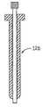
- FIG. 9is an elevational view of a sleeve for an obturator used in conjunction with an oval cannula in accordance with the invention.
- FIG. 10is an elevational view of the obturator
- FIG. 11is a longitudinal section through an assembly consisting of the sleeve and obturator of FIGS. 9 and 10;
- FIG. 12is a longitudinal section through an oval obturator in accordance with the invention.
- FIG. 13is a bottom plan view of the oval obturator of FIG. 12;
- FIG. 14is an elevational view of an oval cannula in accordance with the invention.
- FIG. 15is a bottom plan view of the oval cannula of FIG. 14;
- FIG. 16is a longitudinal section through an assembly of the oval cannula and obturator of FIGS. 12-15;
- FIG. 17is an elevational view of a trephine used with the oval obturator of FIG. 16 .
- the CT scan depicted in FIG. 1shows a vertebral body 20 and a corresponding spinal process 22 in relation to the skin of the patient's back 24 .
- a line 26is drawn on the CT scan through the spinal process and through the center of the vertebral body.
- An oblique line 28is drawn through the center of pedicle 30 to represent the desired path of entry of a guide pin.
- This linewill normally, although not necessarily, intersect line 26 approximately at the point at which line 26 passes through the anterior surface of the vertebral body.
- a measurementis then taken of the distance D between line 26 and the point 32 at which line 28 intersects the skin of the patient's back.
- the approach angle ⁇ between lines 26 and 28is also measured by means of a protractor and noted. The same procedure is carried out on a CT scan of each of the one or more other vertebrae which are to be fixed to the vertebra shown in FIG. 1 .
- the patientis placed prone on a radiolucent frame and operating room table.
- the lumbar lordosisis flattened by flexion of the hips and the table, and care is taken to ensure that the patient is positioned symmetrically in relation to the frame and table.
- a C-arm fluoroscopeis positioned for anteroposterior radiographic visualization of the vertebral bodies at the surgical site.
- the C-armcan be tilted away from the pedicles, for example at an angle of 10 degrees.
- the radiographic observationmust be taken at the patient's midline.
- FIG. 2The radiographic view of the patient's spine, as seen through a fluoroscope, is depicted in FIG. 2, where two adjacent vertebral bodies 20 and 34 are shown, with an intervertebral disc 36 between them.
- the surgeonplaces a first straight, narrow, radiopaque element 38 , for example an 18 gauge needle, over the spinal processes 22 and 40 .
- the element 38When the element 38 is properly positioned, the surgeon draws a vertical line in ink directly on the skin of the patient's back at a location corresponding to the position of the element 38 .
- Similar radiopaque elements 42 and 44are positioned over the centers of pedicles 30 and 45 respectively and arranged perpendicular to the direction of element 38 . Horizontal ink lines are then drawn on the skin of the patient's back at locations corresponding to the locations of elements 42 and 44 .
- a first entry point mark 52is made on horizontal line 48 at a distance D from the vertical line 46 , the distance D having been previously measured on the CT scan through vertebral body 20 and pedicle 30 .
- a second entry point mark 54is made on horizontal line 50 at a distance D′ from vertical line 46 , D′ having been measured on a CT scan of vertebral body 34 .
- a guide pin 56(shown in FIGS. 4 and 5) is inserted through the skin at the entry point 52 (FIG. 3) and passed through the fascia until its tip reaches the pedicle 30 of vertebral body 20 .
- the position of the tip of the guide pin, which should be just lateral to boundary of the pedicle 30is verified by anteroposterior fluoroscopy as in FIG. 4, and appropriate adjustment can be made, if necessary.
- the position of the pin in the middle of the pedicle and parallel to the vertebral plateis verified by lateral fluoroscopic observation, as in FIG. 5, and again adjustments can be made if necessary.
- the guide pin 56is then hammered into the pedicle and into the vertebral body. This is done for the corresponding pedicles of each of the vertebrae to be fixated.
- a protective cannulamay be placed over the pedicle for protection and retraction of the paravertebral muscles while the medullary canal of the pedicle us being tapped. A sound is introduced to make certain that the cortex of the pedicle has not been violated.
- a guide pinis inserted and a pedicle screw is passed over the guide pin and turned by a wrench until it passes the mid point of the anteroposterior diameter of the vertebra.
- the protective cannulamay be left in place while the pedicle screw is being inserted.
- the lengthwise expansible pedicle screw 58which is shown in FIG. 6, comprises a shaft 60 having a distal portion 62 with threads adapted to be threaded into the medullary canal of a vertebral pedicle.
- the shaft 60has a centrally located, multifaceted head 64 for engagement by a wrench, for example a hex wrench, and a proximal portion 66 having machine screw threads 68 .
- a tubular extension 70has internal threads 72 , which are engaged with threads 68 , so that rotation of the extension relative to the pedicle screw shaft 60 , causes the extension to move lengthwise in one direction of the other, thereby increasing or decreasing the effective length of the pedicle screw 58 .
- the threads 68 and 72should fit each other with a close tolerance so that the extension and shaft form a rigid unit when they are locked against relative rotation.
- the pedicle screw shaft 60has an central passage 74 extending lengthwise through it along its axis of elongation. This central passage enables the shaft to be placed over a guide pin.
- the upper end of the tubular extensionhas a threaded recess 76 , with a bottom opening 78 aligned with passage 74 , enabling the guide pin to pass through upper end of the extension.
- holes 80 and 82are provided in upper end face 84 of the extension 70 for receiving projections of a special wrench for rotating the extension.
- the upper end of the extension 70is also formed with wrench-engageable facets 85 , which allow it to be held against rotation by a wrench as an adapter is attached to it.
- the facets 85form a hex nut which is smaller than hex head 64 , thus allowing an elongated socket wrench to be inserted over the extension 70 for engagement with hex head 64 .
- the threaded recess 76 of the extension 70is engageable with threads 86 of an adapter 88 .
- the threads 86extend downward from a plate 90 .
- the platehas notches 92 and 94 for engagement by a special wrench used to tighten it into secure engagement with the extension 70 . These notches are at opposite ends of a raised, part 96 of the plate, the raised part having parallel edges 98 and 100 .
- the raised part 96fits into a slot 102 in a link plate 104 , and the adapter is secured to the link plate by a nut 106 , which engages threads 108 which extend upwardly from the upper face of the adapter.
- the thickness of raised part 96 of the adapteris slightly less than the thickness of plate 104 .
- Mating serrations 110 and 112are provided on the adapter and on the link plate respectively.
- FIG. 8also shows an identical lengthwise expansible pedicle screw 58 ′, which is connectible to a second rectangular slot 102 ′ in link plate 104 by means of an adapter 88 ′ and a nut 106 ′.
- the procedure for locating the insertion points and for determining the angle of approach for the guide pinsprovides for accurate placement of the pins and of the pedicle screws, eliminates the distortion inherent in previous methods, reduces the likelihood of damage to the vertebral structure, and produces generally superior and consistent results.
- the location procedure, using a combination of CT scanning and anteroposterior radiographic observation,is also usable for accurate determination of the insertion point and approach angle for a biopsy cannula and for various other procedures in which a spinal instrument is inserted percutaneously.
- the lengthwise expansible pedicle screwis easily inserted and adjusted, and has as its principal advantage the fact that it eliminates the need to keep adapters of various lengths on hand for possible use in surgery.
- FIGS. 8-17For percutaneous spinal procedures such as decortication of vertebral plates, insertion of bone grafts, removal of herniated disc material and resection of nuclear tissue, the instrumentation depicted in FIGS. 8-17 can be used.
- An obturator 114shown in FIG. 10 is inserted into a guide sleeve 116 , shown in FIG. 9, and the assembly of the obturator and sleeve, as shown in FIG. 11, is passed through the skin, subcutaneous tissue and muscle layer.
- the skin entry pointcan be determined by the size of the patient and a combination of CT scanning and anteroposterior and lateral radiographic observation in the same manner as in the case of the insertion of pedicle screws. Typically, the entry point is about 10-12 cm. from the midline.
- the tip of the obturator 114is located either at the mid pedicle or lateral pedicle line.
- the tip of the obturator and sleeve assemblyshould be touching a line drawn posterior to the backs of the vertebrae adjacent to the intervertebral disc which is being accessed.
- An obturator 118having a longitudinal passage 120 and a blunt end 122 , as shown in FIGS. 12 and 13, is inserted into a cannula 124 , as shown in FIGS. 14 and 15.
- the cannulahas an oval cross-section, and the body of the obturator 118 also has an oval cross-section, conforming to the interior wall of the cannula.
- the major axis of the lumen of the cannulais preferably in the range of 7 to 12 mm, and the minor axis is preferably in the range of 3 to 5 mm.
- a typical cannulacan have a 3 ⁇ 7 mm lumen, a 5 ⁇ 12 lumen, or even a 3 ⁇ 12 or 5 ⁇ 7 lumen.
- the obturator 114is removed from the sleeve 116 , and the assembly of the cannula and obturator, as shown in FIG. 16, is passed over the guide sleeve 116 and directed toward the annulus fibrosis. The obturator and guide sleeve are then removed, leaving the cannula 124 in place.
- a zero degree arthroscopeis inserted to inspect the annular surface to make certain that neural structures are not in the path of the inserted cannula.
- a trephine 126shown in FIG. 17, is inserted through the passage in the obturator to sever the annular fibers, and the oval cannula is inserted into the fenestration formed by the trephine and engaged into the annular fibers.
- the trephinetypically has an outer diameter of 4.5 mm.
- the annular fenestrationmay also be performed, under direct arthroscopic visualization and magnification, by a long and thin handle knife which is introduced into the lumen of the oval cannula.
- oval cannulaalso may be used for the insertion of expandable cages which are utilized for fusion of the two adjacent vertebrae or the introduction of a disc prosthesis.
- the steps which were described for insertion of a guide pin into the pedicleare followed by introduction of a cannulated drill with an outer diameter not exceeding 7 mm over the guide pin.
- the drillis driven through the medullary canal of the pedicle into the vertebral body of the desired vertebra.
- a cannulais then inserted into the pedicle following the removal of the cannulated drill.
- Straight and upbiting biopsy forcepsis passed through the cannula for harvesting of abnormal tissue.
- the oval shape of the lumen of the cannulapermits simultaneous introduction of an arthroscope and forceps for removal of herniated disc material and resection of nuclear tissue.
- auxiliary cannulacan be of comparatively small diameter, e.g. 5 mm.
- Curettes and reamersare passed through the oval cannula while an arthroscope, e.g. a 30 or 70 degree arthroscope is introduced into the intervertebral disc through the auxiliary cannula from the opposite portal.
- Decortication of the vertebral platesis carried out under direct arthroscopic magnification and illumination.
- Autogenous boneharvested from the patient's ilium, is passed through the cannulae and packed between the vertebral plates of the proximal and distal vertebrae. Afterwards, the instruments are withdrawn and the wound is closed.
- the oval cannulahas the advantage that it allows plural instruments, e.g. an arthroscope and a forceps to extend through it at the same time, thereby eliminating the need for a separate cannula on the same side of the spine as in U.S. Pat. No. 5,395,317.
- the oval cross-sectionis also advantageous in that it accommodates decorticators having blades with comparatively large lateral dimensions, e.g. 7 mm or 9 mm, for access to the concave surfaces of the vertebral plates.
- the decorticatorcan be rotated after the blades at its distal end pass beyond the opening at the distal end of the oval cannula.
- the use of the oval obturatorallows the oval cannula to be introduced readily with a minimum number of steps, and provides guidance for the trephine used to fenestrate the annulus fibrosis of the disc.
Landscapes
- Health & Medical Sciences (AREA)
- Orthopedic Medicine & Surgery (AREA)
- Surgery (AREA)
- Life Sciences & Earth Sciences (AREA)
- Neurology (AREA)
- Biomedical Technology (AREA)
- Animal Behavior & Ethology (AREA)
- Engineering & Computer Science (AREA)
- Veterinary Medicine (AREA)
- Heart & Thoracic Surgery (AREA)
- Medical Informatics (AREA)
- Molecular Biology (AREA)
- Nuclear Medicine, Radiotherapy & Molecular Imaging (AREA)
- General Health & Medical Sciences (AREA)
- Public Health (AREA)
- Oral & Maxillofacial Surgery (AREA)
- Dentistry (AREA)
- Surgical Instruments (AREA)
- Prostheses (AREA)
Abstract
Description
Claims (13)
Priority Applications (2)
| Application Number | Priority Date | Filing Date | Title |
|---|---|---|---|
| US09/711,614US6596008B1 (en) | 1997-07-15 | 2000-11-13 | Method and instruments for percutaneous arthroscopic disc removal, bone biopsy and fixation of the vertebral |
| US11/186,016USRE44268E1 (en) | 1997-07-15 | 2005-07-20 | Method and instruments for percutaneous arthroscopic disc removal, bone biopsy and fixation of the vertebral |
Applications Claiming Priority (3)
| Application Number | Priority Date | Filing Date | Title |
|---|---|---|---|
| US08/893,286US5964761A (en) | 1997-07-15 | 1997-07-15 | Method and instruments for percutaneous arthroscopic disc removal, bone biopsy and fixation of vertebrae |
| US09/370,318US6175758B1 (en) | 1997-07-15 | 1999-08-09 | Method for percutaneous arthroscopic disc removal, bone biopsy and fixation of the vertebrae |
| US09/711,614US6596008B1 (en) | 1997-07-15 | 2000-11-13 | Method and instruments for percutaneous arthroscopic disc removal, bone biopsy and fixation of the vertebral |
Related Parent Applications (1)
| Application Number | Title | Priority Date | Filing Date |
|---|---|---|---|
| US09/370,318DivisionUS6175758B1 (en) | 1997-07-15 | 1999-08-09 | Method for percutaneous arthroscopic disc removal, bone biopsy and fixation of the vertebrae |
Related Child Applications (1)
| Application Number | Title | Priority Date | Filing Date |
|---|---|---|---|
| US11/186,016ReissueUSRE44268E1 (en) | 1997-07-15 | 2005-07-20 | Method and instruments for percutaneous arthroscopic disc removal, bone biopsy and fixation of the vertebral |
Publications (1)
| Publication Number | Publication Date |
|---|---|
| US6596008B1true US6596008B1 (en) | 2003-07-22 |
Family
ID=27004901
Family Applications (3)
| Application Number | Title | Priority Date | Filing Date |
|---|---|---|---|
| US09/370,318Expired - Fee RelatedUS6175758B1 (en) | 1997-07-15 | 1999-08-09 | Method for percutaneous arthroscopic disc removal, bone biopsy and fixation of the vertebrae |
| US09/711,614CeasedUS6596008B1 (en) | 1997-07-15 | 2000-11-13 | Method and instruments for percutaneous arthroscopic disc removal, bone biopsy and fixation of the vertebral |
| US11/186,016Expired - LifetimeUSRE44268E1 (en) | 1997-07-15 | 2005-07-20 | Method and instruments for percutaneous arthroscopic disc removal, bone biopsy and fixation of the vertebral |
Family Applications Before (1)
| Application Number | Title | Priority Date | Filing Date |
|---|---|---|---|
| US09/370,318Expired - Fee RelatedUS6175758B1 (en) | 1997-07-15 | 1999-08-09 | Method for percutaneous arthroscopic disc removal, bone biopsy and fixation of the vertebrae |
Family Applications After (1)
| Application Number | Title | Priority Date | Filing Date |
|---|---|---|---|
| US11/186,016Expired - LifetimeUSRE44268E1 (en) | 1997-07-15 | 2005-07-20 | Method and instruments for percutaneous arthroscopic disc removal, bone biopsy and fixation of the vertebral |
Country Status (1)
| Country | Link |
|---|---|
| US (3) | US6175758B1 (en) |
Cited By (93)
| Publication number | Priority date | Publication date | Assignee | Title |
|---|---|---|---|---|
| US20040116777A1 (en)* | 2002-12-13 | 2004-06-17 | Jeffrey Larson | Guided retractor and methods of use |
| US20040181231A1 (en)* | 2003-03-13 | 2004-09-16 | Centerpulse Spine-Tech, Inc. | Spinal access instrument |
| US20050038440A1 (en)* | 2002-12-13 | 2005-02-17 | Jeffrey Larson | Guided retractor and methods of use |
| US20050065515A1 (en)* | 2003-09-24 | 2005-03-24 | Tae-Ahn Jahng | Marking and guidance method and system for flexible fixation of a spine |
| US20050075540A1 (en)* | 2003-08-26 | 2005-04-07 | Shluzas Alan E. | Minimally invasive access device and method |
| US20050215862A1 (en)* | 2003-11-26 | 2005-09-29 | Jeffrey Larson | Guided retractor and methods of use |
| US20050273131A1 (en)* | 2003-08-26 | 2005-12-08 | Shluzas Alan E | Access systems and methods for minimally invasive surgery |
| US20060052812A1 (en)* | 2004-09-07 | 2006-03-09 | Michael Winer | Tool for preparing a surgical site for an access device |
| US20060069404A1 (en)* | 2004-03-31 | 2006-03-30 | Shluzas Alan E | Access device having discrete visualization locations |
| US20060155170A1 (en)* | 2002-12-13 | 2006-07-13 | Synthes Spine Company, Lp | Guided retractor and methods of use |
| US20060264962A1 (en)* | 2003-09-24 | 2006-11-23 | Chin Kingsley R | System and method for spinal implant placement |
| US20060264934A1 (en)* | 2005-05-18 | 2006-11-23 | Medicinelodge, Inc. | System and method for orthopedic implant configuration |
| US20070083210A1 (en)* | 2005-09-16 | 2007-04-12 | Zimmer Spine, Inc. | Apparatus and method for minimally invasive spine surgery |
| US20080195150A1 (en)* | 2007-02-12 | 2008-08-14 | Bishop Randolph C | Spinal stabilization system for the stabilization and fixation of the lumbar spine and method for using same |
| US20080228184A1 (en)* | 2007-03-15 | 2008-09-18 | Zimmer Spine, Inc. | System and method for minimally invasive spinal surgery |
| US20090099605A1 (en)* | 2006-02-06 | 2009-04-16 | Stryker Spine | Rod contouring apparatus for percutaneous pedicle screw extension |
| US7547326B2 (en) | 2005-04-29 | 2009-06-16 | Jmea Corporation | Disc annulus repair system |
| US7608108B2 (en) | 2005-04-29 | 2009-10-27 | Jmea Corporation | Tissue repair system |
| US20100256766A1 (en)* | 2009-04-07 | 2010-10-07 | Hibri Nadi S | Percutaneous Implantable Nuclear Prosthesis |
| US7955355B2 (en) | 2003-09-24 | 2011-06-07 | Stryker Spine | Methods and devices for improving percutaneous access in minimally invasive surgeries |
| US20110230884A1 (en)* | 2008-06-24 | 2011-09-22 | Adam Mantzaris | Hybrid intramedullary fixation assembly and method of use |
| US8211126B2 (en) | 2009-09-22 | 2012-07-03 | Jmea Corporation | Tissue repair system |
| US8303589B2 (en) | 2008-06-24 | 2012-11-06 | Extremity Medical Llc | Fixation system, an intramedullary fixation assembly and method of use |
| US8328806B2 (en) | 2008-06-24 | 2012-12-11 | Extremity Medical, Llc | Fixation system, an intramedullary fixation assembly and method of use |
| US8343199B2 (en) | 2008-06-24 | 2013-01-01 | Extremity Medical, Llc | Intramedullary fixation screw, a fixation system, and method of fixation of the subtalar joint |
| US8394129B2 (en) | 2011-03-10 | 2013-03-12 | Interventional Spine, Inc. | Method and apparatus for minimally invasive insertion of intervertebral implants |
| USRE44268E1 (en) | 1997-07-15 | 2013-06-04 | Zimmer Spine, Inc. | Method and instruments for percutaneous arthroscopic disc removal, bone biopsy and fixation of the vertebral |
| US8518087B2 (en) | 2011-03-10 | 2013-08-27 | Interventional Spine, Inc. | Method and apparatus for minimally invasive insertion of intervertebral implants |
| US8702718B2 (en) | 2005-04-29 | 2014-04-22 | Jmea Corporation | Implantation system for tissue repair |
| US8920476B2 (en) | 2008-06-24 | 2014-12-30 | Extremity Medical, Llc | Fixation system, an intramedullary fixation assembly and method of use |
| US8979900B2 (en) | 2003-09-24 | 2015-03-17 | DePuy Synthes Products, LLC | Spinal stabilization device |
| US9017329B2 (en) | 2008-06-24 | 2015-04-28 | Extremity Medical, Llc | Intramedullary fixation assembly and method of use |
| US9044282B2 (en) | 2008-06-24 | 2015-06-02 | Extremity Medical Llc | Intraosseous intramedullary fixation assembly and method of use |
| US9216015B2 (en) | 2004-10-28 | 2015-12-22 | Vycor Medical, Inc. | Apparatus and methods for performing brain surgery |
| US9277928B2 (en) | 2013-03-11 | 2016-03-08 | Interventional Spine, Inc. | Method and apparatus for minimally invasive insertion of intervertebral implants |
| US9289220B2 (en) | 2008-06-24 | 2016-03-22 | Extremity Medical Llc | Intramedullary fixation assembly and method of use |
| US9295479B2 (en) | 2013-03-14 | 2016-03-29 | Spinal Stabilization Technologies, Llc | Surgical device |
| US9307969B2 (en) | 2005-06-17 | 2016-04-12 | Vycor Medical, Inc. | Tissue retractor apparatus and methods |
| US9408716B1 (en) | 2013-12-06 | 2016-08-09 | Stryker European Holdings I, Llc | Percutaneous posterior spinal fusion implant construction and method |
| US20160262800A1 (en)* | 2015-02-13 | 2016-09-15 | Nuvasive, Inc. | Systems and methods for planning, performing, and assessing spinal correction during surgery |
| US9510875B2 (en) | 2013-03-14 | 2016-12-06 | Stryker European Holdings I, Llc | Systems and methods for percutaneous spinal fusion |
| US9522070B2 (en) | 2013-03-07 | 2016-12-20 | Interventional Spine, Inc. | Intervertebral implant |
| US9545321B2 (en) | 2013-03-14 | 2017-01-17 | Spinal Stabilization Technologies Llc | Prosthetic spinal disk nucleus |
| US9737287B2 (en) | 2014-05-13 | 2017-08-22 | Vycor Medical, Inc. | Guidance system mounts for surgical introducers |
| US9744050B1 (en) | 2013-12-06 | 2017-08-29 | Stryker European Holdings I, Llc | Compression and distraction system for percutaneous posterior spinal fusion |
| US9827020B2 (en) | 2013-03-14 | 2017-11-28 | Stryker European Holdings I, Llc | Percutaneous spinal cross link system and method |
| US9839530B2 (en) | 2007-06-26 | 2017-12-12 | DePuy Synthes Products, Inc. | Highly lordosed fusion cage |
| US9883951B2 (en) | 2012-08-30 | 2018-02-06 | Interventional Spine, Inc. | Artificial disc |
| US9895236B2 (en) | 2010-06-24 | 2018-02-20 | DePuy Synthes Products, Inc. | Enhanced cage insertion assembly |
| US9913727B2 (en) | 2015-07-02 | 2018-03-13 | Medos International Sarl | Expandable implant |
| US9931223B2 (en) | 2008-04-05 | 2018-04-03 | DePuy Synthes Products, Inc. | Expandable intervertebral implant |
| US9993349B2 (en) | 2002-06-27 | 2018-06-12 | DePuy Synthes Products, Inc. | Intervertebral disc |
| US9993353B2 (en) | 2013-03-14 | 2018-06-12 | DePuy Synthes Products, Inc. | Method and apparatus for minimally invasive insertion of intervertebral implants |
| US10034690B2 (en) | 2014-12-09 | 2018-07-31 | John A. Heflin | Spine alignment system |
| US10058433B2 (en) | 2012-07-26 | 2018-08-28 | DePuy Synthes Products, Inc. | Expandable implant |
| US10159579B1 (en) | 2013-12-06 | 2018-12-25 | Stryker European Holdings I, Llc | Tubular instruments for percutaneous posterior spinal fusion systems and methods |
| US10376258B2 (en) | 2016-11-07 | 2019-08-13 | Vycor Medical, Inc. | Surgical introducer with guidance system receptacle |
| US10390963B2 (en) | 2006-12-07 | 2019-08-27 | DePuy Synthes Products, Inc. | Intervertebral implant |
| US10398563B2 (en) | 2017-05-08 | 2019-09-03 | Medos International Sarl | Expandable cage |
| US10433977B2 (en) | 2008-01-17 | 2019-10-08 | DePuy Synthes Products, Inc. | Expandable intervertebral implant and associated method of manufacturing the same |
| US10500062B2 (en) | 2009-12-10 | 2019-12-10 | DePuy Synthes Products, Inc. | Bellows-like expandable interbody fusion cage |
| US10537436B2 (en) | 2016-11-01 | 2020-01-21 | DePuy Synthes Products, Inc. | Curved expandable cage |
| US10543016B2 (en) | 2016-11-07 | 2020-01-28 | Vycor Medical, Inc. | Surgical introducer with guidance system receptacle |
| US10548741B2 (en) | 2010-06-29 | 2020-02-04 | DePuy Synthes Products, Inc. | Distractible intervertebral implant |
| US10575967B2 (en) | 2015-09-01 | 2020-03-03 | Spinal Stabilization Technologies Llc | Implantable nuclear prosthesis |
| US10888433B2 (en) | 2016-12-14 | 2021-01-12 | DePuy Synthes Products, Inc. | Intervertebral implant inserter and related methods |
| US10940016B2 (en) | 2017-07-05 | 2021-03-09 | Medos International Sarl | Expandable intervertebral fusion cage |
| US11331090B2 (en) | 2015-09-04 | 2022-05-17 | Medos International Sarl | Surgical visualization systems and related methods |
| US11344424B2 (en) | 2017-06-14 | 2022-05-31 | Medos International Sarl | Expandable intervertebral implant and related methods |
| US11426290B2 (en) | 2015-03-06 | 2022-08-30 | DePuy Synthes Products, Inc. | Expandable intervertebral implant, system, kit and method |
| US11426286B2 (en) | 2020-03-06 | 2022-08-30 | Eit Emerging Implant Technologies Gmbh | Expandable intervertebral implant |
| US11439380B2 (en) | 2015-09-04 | 2022-09-13 | Medos International Sarl | Surgical instrument connectors and related methods |
| US11446156B2 (en) | 2018-10-25 | 2022-09-20 | Medos International Sarl | Expandable intervertebral implant, inserter instrument, and related methods |
| US11452607B2 (en) | 2010-10-11 | 2022-09-27 | DePuy Synthes Products, Inc. | Expandable interspinous process spacer implant |
| US11510788B2 (en) | 2016-06-28 | 2022-11-29 | Eit Emerging Implant Technologies Gmbh | Expandable, angularly adjustable intervertebral cages |
| US11559328B2 (en) | 2015-09-04 | 2023-01-24 | Medos International Sarl | Multi-shield spinal access system |
| US11576727B2 (en) | 2016-03-02 | 2023-02-14 | Nuvasive, Inc. | Systems and methods for spinal correction surgical planning |
| US11596522B2 (en) | 2016-06-28 | 2023-03-07 | Eit Emerging Implant Technologies Gmbh | Expandable and angularly adjustable intervertebral cages with articulating joint |
| US11612491B2 (en) | 2009-03-30 | 2023-03-28 | DePuy Synthes Products, Inc. | Zero profile spinal fusion cage |
| US11633287B2 (en) | 2014-11-04 | 2023-04-25 | Spinal Stabilization Technologies Llc | Percutaneous implantable nuclear prosthesis |
| US11638649B2 (en) | 2014-11-04 | 2023-05-02 | Spinal Stabilization Technologies Llc | Percutaneous implantable nuclear prosthesis |
| US11672562B2 (en) | 2015-09-04 | 2023-06-13 | Medos International Sarl | Multi-shield spinal access system |
| US11744710B2 (en) | 2018-09-04 | 2023-09-05 | Spinal Stabilization Technologies Llc | Implantable nuclear prosthesis, kits, and related methods |
| US11744447B2 (en) | 2015-09-04 | 2023-09-05 | Medos International | Surgical visualization systems and related methods |
| US11752009B2 (en) | 2021-04-06 | 2023-09-12 | Medos International Sarl | Expandable intervertebral fusion cage |
| US11850160B2 (en) | 2021-03-26 | 2023-12-26 | Medos International Sarl | Expandable lordotic intervertebral fusion cage |
| US11911287B2 (en) | 2010-06-24 | 2024-02-27 | DePuy Synthes Products, Inc. | Lateral spondylolisthesis reduction cage |
| USRE49973E1 (en) | 2013-02-28 | 2024-05-21 | DePuy Synthes Products, Inc. | Expandable intervertebral implant, system, kit and method |
| US12090064B2 (en) | 2022-03-01 | 2024-09-17 | Medos International Sarl | Stabilization members for expandable intervertebral implants, and related systems and methods |
| US12150636B2 (en) | 2015-09-04 | 2024-11-26 | Medos International Sárl | Surgical instrument connectors and related methods |
| US12178469B2 (en) | 2016-11-07 | 2024-12-31 | Vycor Medical Inc. | Surgical introducer with guidance system receptacle |
| US12357384B2 (en) | 2013-03-15 | 2025-07-15 | Nuvasive, Inc. | Spinal balance assessment |
| US12440346B2 (en) | 2023-03-31 | 2025-10-14 | DePuy Synthes Products, Inc. | Expandable intervertebral implant |
Families Citing this family (78)
| Publication number | Priority date | Publication date | Assignee | Title |
|---|---|---|---|---|
| US7799036B2 (en)* | 1998-08-20 | 2010-09-21 | Zimmer Spine, Inc. | Method and apparatus for securing vertebrae |
| US6187000B1 (en)* | 1998-08-20 | 2001-02-13 | Endius Incorporated | Cannula for receiving surgical instruments |
| US7641670B2 (en)* | 1998-08-20 | 2010-01-05 | Zimmer Spine, Inc. | Cannula for receiving surgical instruments |
| US7682370B2 (en)* | 1998-08-20 | 2010-03-23 | Zimmer Spine, Inc. | Surgical tool for use in expanding a cannula |
| US7641657B2 (en)* | 2003-06-10 | 2010-01-05 | Trans1, Inc. | Method and apparatus for providing posterior or anterior trans-sacral access to spinal vertebrae |
| US7717958B2 (en) | 2000-02-16 | 2010-05-18 | Trans1, Inc. | Prosthetic nucleus apparatus |
| US6899716B2 (en) | 2000-02-16 | 2005-05-31 | Trans1, Inc. | Method and apparatus for spinal augmentation |
| US6558386B1 (en)* | 2000-02-16 | 2003-05-06 | Trans1 Inc. | Axial spinal implant and method and apparatus for implanting an axial spinal implant within the vertebrae of the spine |
| US6740090B1 (en) | 2000-02-16 | 2004-05-25 | Trans1 Inc. | Methods and apparatus for forming shaped axial bores through spinal vertebrae |
| US20030191474A1 (en)* | 2000-02-16 | 2003-10-09 | Cragg Andrew H. | Apparatus for performing a discectomy through a trans-sacral axial bore within the vertebrae of the spine |
| US7014633B2 (en) | 2000-02-16 | 2006-03-21 | Trans1, Inc. | Methods of performing procedures in the spine |
| US6558390B2 (en) | 2000-02-16 | 2003-05-06 | Axiamed, Inc. | Methods and apparatus for performing therapeutic procedures in the spine |
| US7744599B2 (en)* | 2000-02-16 | 2010-06-29 | Trans1 Inc. | Articulating spinal implant |
| US6575979B1 (en) | 2000-02-16 | 2003-06-10 | Axiamed, Inc. | Method and apparatus for providing posterior or anterior trans-sacral access to spinal vertebrae |
| EP1292239B1 (en)* | 2000-06-23 | 2013-02-13 | University Of Southern California | Percutaneous vertebral fusion system |
| US6749614B2 (en) | 2000-06-23 | 2004-06-15 | Vertelink Corporation | Formable orthopedic fixation system with cross linking |
| US6899713B2 (en)* | 2000-06-23 | 2005-05-31 | Vertelink Corporation | Formable orthopedic fixation system |
| US6875212B2 (en)* | 2000-06-23 | 2005-04-05 | Vertelink Corporation | Curable media for implantable medical device |
| US6964667B2 (en)* | 2000-06-23 | 2005-11-15 | Sdgi Holdings, Inc. | Formed in place fixation system with thermal acceleration |
| US7056321B2 (en)* | 2000-08-01 | 2006-06-06 | Endius, Incorporated | Method of securing vertebrae |
| US7985247B2 (en) | 2000-08-01 | 2011-07-26 | Zimmer Spine, Inc. | Methods and apparatuses for treating the spine through an access device |
| CA2429246C (en) | 2000-08-08 | 2011-06-07 | Vincent Bryan | Implantable joint prosthesis |
| JP2004516044A (en)* | 2000-08-08 | 2004-06-03 | エスディージーアイ・ホールディングス・インコーポレーテッド | Method and apparatus for improving stereotactic body transplantation |
| US7144393B2 (en)* | 2001-05-15 | 2006-12-05 | Dipoto Gene P | Structure for receiving surgical instruments |
| US9155544B2 (en)* | 2002-03-20 | 2015-10-13 | P Tech, Llc | Robotic systems and methods |
| US7464145B2 (en)* | 2002-07-11 | 2008-12-09 | Intelliden, Inc. | Repository-independent system and method for asset management and reconciliation |
| US20050267354A1 (en)* | 2003-02-04 | 2005-12-01 | Joel Marquart | System and method for providing computer assistance with spinal fixation procedures |
| US7648509B2 (en) | 2003-03-10 | 2010-01-19 | Ilion Medical Llc | Sacroiliac joint immobilization |
| US7473267B2 (en)* | 2003-04-25 | 2009-01-06 | Warsaw Orthopedic, Inc. | System and method for minimally invasive posterior fixation |
| US7194120B2 (en)* | 2003-05-29 | 2007-03-20 | Board Of Regents, The University Of Texas System | Methods and systems for image-guided placement of implants |
| US7815665B2 (en)* | 2003-09-24 | 2010-10-19 | N Spine, Inc. | Adjustable spinal stabilization system |
| AU2004283727A1 (en)* | 2003-10-23 | 2005-05-06 | Trans1 Inc. | Tools and tool kits for performing minimally invasive procedures on the spine |
| CN101816588A (en)* | 2004-02-20 | 2010-09-01 | 赫克托·O·帕切科 | Adjustable awl for punching |
| US20060004398A1 (en)* | 2004-07-02 | 2006-01-05 | Binder Lawrence J Jr | Sequential dilator system |
| US7666189B2 (en)* | 2004-09-29 | 2010-02-23 | Synthes Usa, Llc | Less invasive surgical system and methods |
| US20060195091A1 (en)* | 2005-02-15 | 2006-08-31 | Mcgraw J K | Percutaneous spinal stabilization device and method |
| US7623902B2 (en)* | 2005-03-07 | 2009-11-24 | Leucadia 6, Llc | System and methods for improved access to vertebral bodies for kyphoplasty, vertebroplasty, vertebral body biopsy or screw placement |
| US7628800B2 (en)* | 2005-06-03 | 2009-12-08 | Warsaw Orthopedic, Inc. | Formed in place corpectomy device |
| WO2007021772A2 (en)* | 2005-08-09 | 2007-02-22 | Trans1, Inc. | Exchange system for axial spinal procedures |
| US20070237307A1 (en)* | 2006-03-03 | 2007-10-11 | Loubert Suddaby | Radiographic spine marker |
| EP2032023A4 (en)* | 2006-06-28 | 2011-08-10 | Hector O Pacheco | Templating and placing artifical discs in spine |
| US8663328B2 (en)* | 2006-12-21 | 2014-03-04 | Warsaw Orthopedic, Inc. | Methods for positioning a load-bearing component of an orthopedic implant device by inserting a malleable device that hardens in vivo |
| US7771476B2 (en) | 2006-12-21 | 2010-08-10 | Warsaw Orthopedic Inc. | Curable orthopedic implant devices configured to harden after placement in vivo by application of a cure-initiating energy before insertion |
| US8480718B2 (en)* | 2006-12-21 | 2013-07-09 | Warsaw Orthopedic, Inc. | Curable orthopedic implant devices configured to be hardened after placement in vivo |
| US8758407B2 (en)* | 2006-12-21 | 2014-06-24 | Warsaw Orthopedic, Inc. | Methods for positioning a load-bearing orthopedic implant device in vivo |
| US20090024174A1 (en) | 2007-07-17 | 2009-01-22 | Stark John G | Bone screws and particular applications to sacroiliac joint fusion |
| BRPI0818608A2 (en) | 2007-10-05 | 2015-04-22 | Synthes Gmbh | Sequential directional dilatation system for dilating from a nerve of a patient's anatomy, and method for forming an access opening through a psoas muscle to a patient's spine using a dilatation system |
| US8781555B2 (en) | 2007-11-26 | 2014-07-15 | C. R. Bard, Inc. | System for placement of a catheter including a signal-generating stylet |
| US20100111389A1 (en)* | 2007-12-06 | 2010-05-06 | Siemens Medical Solutions Usa, Inc. | System and method for planning and guiding percutaneous procedures |
| US8986318B2 (en) | 2008-06-03 | 2015-03-24 | Jeffrey Scott Smith | Pedicle depth measuring apparatus |
| US9668775B2 (en) | 2008-06-03 | 2017-06-06 | Jeffrey Scott Smith | Pedicle screw |
| US8075579B2 (en)* | 2008-01-17 | 2011-12-13 | Life Spine, Inc. | Pedicle dart system |
| US8236006B2 (en)* | 2008-01-17 | 2012-08-07 | Life Spine, Inc. | One step entry pedicular preparation device and disc access system |
| US8740912B2 (en) | 2008-02-27 | 2014-06-03 | Ilion Medical Llc | Tools for performing less invasive orthopedic joint procedures |
| WO2010078029A1 (en)* | 2008-12-17 | 2010-07-08 | Synthes Usa, Llc | Posterior spine dynamic stabilizer |
| US20110112373A1 (en)* | 2009-11-10 | 2011-05-12 | Trans1 Inc. | Soft tissue access apparatus and methods for spinal surgery |
| US8926508B2 (en)* | 2009-12-17 | 2015-01-06 | Covidien Lp | Access assembly with dual anchor and seal capabilities |
| CA3002234C (en) | 2010-01-13 | 2020-07-28 | Jcbd, Llc | Sacroiliac joint fixation fusion system |
| US9333090B2 (en) | 2010-01-13 | 2016-05-10 | Jcbd, Llc | Systems for and methods of fusing a sacroiliac joint |
| WO2014015309A1 (en) | 2012-07-20 | 2014-01-23 | Jcbd, Llc | Orthopedic anchoring system and methods |
| US9421109B2 (en) | 2010-01-13 | 2016-08-23 | Jcbd, Llc | Systems and methods of fusing a sacroiliac joint |
| US9381045B2 (en) | 2010-01-13 | 2016-07-05 | Jcbd, Llc | Sacroiliac joint implant and sacroiliac joint instrument for fusing a sacroiliac joint |
| EP2720628B1 (en) | 2011-06-17 | 2021-08-11 | Jcbd, Llc | Sacroiliac joint implant system |
| WO2014159225A2 (en) | 2013-03-14 | 2014-10-02 | Baxano Surgical, Inc. | Spinal implants and implantation system |
| US9717539B2 (en) | 2013-07-30 | 2017-08-01 | Jcbd, Llc | Implants, systems, and methods for fusing a sacroiliac joint |
| US9510872B2 (en) | 2013-03-15 | 2016-12-06 | Jcbd, Llc | Spinal stabilization system |
| US10245087B2 (en) | 2013-03-15 | 2019-04-02 | Jcbd, Llc | Systems and methods for fusing a sacroiliac joint and anchoring an orthopedic appliance |
| US9826986B2 (en) | 2013-07-30 | 2017-11-28 | Jcbd, Llc | Systems for and methods of preparing a sacroiliac joint for fusion |
| US9700356B2 (en) | 2013-07-30 | 2017-07-11 | Jcbd, Llc | Systems for and methods of fusing a sacroiliac joint |
| US9801546B2 (en) | 2014-05-27 | 2017-10-31 | Jcbd, Llc | Systems for and methods of diagnosing and treating a sacroiliac joint disorder |
| US9883898B2 (en) | 2014-08-07 | 2018-02-06 | Jeffrey Scott Smith | Pedicle screw with electro-conductive coating or portion |
| AU2017235887B2 (en)* | 2016-09-26 | 2021-09-30 | K2M, Inc. | Retraction system and method of use |
| EP3531946A4 (en) | 2016-10-27 | 2020-10-21 | Leucadia 6, LLC | INTRAOPERATIVE FLUOROSCOPIC REGISTRATION OF VERTEBRAL BODIES |
| CN107468314A (en)* | 2017-08-01 | 2017-12-15 | 三亚市中医院 | A kind of multi-functional Thoracolumbar disk body surface locator system |
| US10603055B2 (en) | 2017-09-15 | 2020-03-31 | Jcbd, Llc | Systems for and methods of preparing and fusing a sacroiliac joint |
| CN108078622A (en)* | 2018-02-09 | 2018-05-29 | 陕西东望科技有限公司 | It is a kind of to take root in the percutaneous guide plate used nail art suitable for vertebral arch |
| JP7440024B2 (en)* | 2018-06-15 | 2024-02-28 | ネオ・メディカル・ソシエテ・アノニム | pedicle marker |
| US20220241017A1 (en)* | 2021-02-01 | 2022-08-04 | Mazor Robotics Ltd. | Systems and methods for rod insertion planning and rod insertion |
Citations (10)
| Publication number | Priority date | Publication date | Assignee | Title |
|---|---|---|---|---|
| US4545374A (en) | 1982-09-03 | 1985-10-08 | Jacobson Robert E | Method and instruments for performing a percutaneous lumbar diskectomy |
| US4573448A (en) | 1983-10-05 | 1986-03-04 | Pilling Co. | Method for decompressing herniated intervertebral discs |
| US4583538A (en) | 1984-05-04 | 1986-04-22 | Onik Gary M | Method and apparatus for stereotaxic placement of probes in the body utilizing CT scanner localization |
| US5242443A (en) | 1991-08-15 | 1993-09-07 | Smith & Nephew Dyonics, Inc. | Percutaneous fixation of vertebrae |
| US5395317A (en) | 1991-10-30 | 1995-03-07 | Smith & Nephew Dyonics, Inc. | Unilateral biportal percutaneous surgical procedure |
| US5480440A (en) | 1991-08-15 | 1996-01-02 | Smith & Nephew Richards, Inc. | Open surgical technique for vertebral fixation with subcutaneous fixators positioned between the skin and the lumbar fascia of a patient |
| US5540690A (en) | 1991-07-15 | 1996-07-30 | Danek Group Inc. | Spinal fixation system |
| US5752955A (en) | 1995-10-30 | 1998-05-19 | Fastenetix, L.L.C. | Sliding shaft variable length cross-link device for use with dual rod apparatus |
| US6021342A (en) | 1997-06-30 | 2000-02-01 | Neorad A/S | Apparatus for assisting percutaneous computed tomography-guided surgical activity |
| US6064904A (en) | 1997-11-28 | 2000-05-16 | Picker International, Inc. | Frameless stereotactic CT scanner with virtual needle display for planning image guided interventional procedures |
Family Cites Families (109)
| Publication number | Priority date | Publication date | Assignee | Title |
|---|---|---|---|---|
| US530728A (en) | 1894-12-11 | Speculum | ||
| US151228A (en) | 1874-05-26 | Improvement in surgical speculum | ||
| US1170324A (en) | 1912-02-02 | 1916-02-01 | Myron B Pomerene | Dilating-forceps. |
| US3044461A (en) | 1960-01-21 | 1962-07-17 | Murdock Barbara | Procto-sigmoidoscope |
| US3503398A (en) | 1965-09-10 | 1970-03-31 | American Hospital Supply Corp | Atraumatic clamp for vascular surgery |
| US3789852A (en) | 1972-06-12 | 1974-02-05 | S Kim | Expandable trochar, especially for medical purposes |
| US3965890A (en) | 1974-10-18 | 1976-06-29 | William Kohlmann Gauthier | Surgical retractor |
| DE3025785C2 (en) | 1980-07-08 | 1984-08-16 | Storz, Karl, 7200 Tuttlingen | Dilator, method for its use and device for carrying out the method |
| DE3117802A1 (en) | 1981-05-06 | 1982-11-25 | Max Dr. 8520 Erlangen Hubmann | CATHETER CUTLERY |
| GB8424436D0 (en) | 1984-09-27 | 1984-10-31 | Pratt Int Ltd Burnerd | Surgical appliance |
| US4583458A (en)* | 1985-03-22 | 1986-04-22 | Beachum Gary T | Multi-station silk screen printer for printing varying indicia |
| GB8513702D0 (en) | 1985-05-30 | 1985-07-03 | Gill S S | Expansible trocar |
| US4601713A (en) | 1985-06-11 | 1986-07-22 | Genus Catheter Technologies, Inc. | Variable diameter catheter |
| US4784118A (en) | 1987-04-28 | 1988-11-15 | Endotherapeutics | Optical viewing device |
| US4863133A (en) | 1987-05-26 | 1989-09-05 | Leonard Medical | Arm device for adjustable positioning of a medical instrument or the like |
| US4817587A (en) | 1987-08-31 | 1989-04-04 | Janese Woodrow W | Ring para-spinal retractor |
| US4921478A (en) | 1988-02-23 | 1990-05-01 | C. R. Bard, Inc. | Cerebral balloon angioplasty system |
| US4895564A (en)* | 1988-06-08 | 1990-01-23 | Farrell Edward M | Percutaneous femoral bypass system |
| US5484437A (en) | 1988-06-13 | 1996-01-16 | Michelson; Gary K. | Apparatus and method of inserting spinal implants |
| US6120437A (en) | 1988-07-22 | 2000-09-19 | Inbae Yoon | Methods for creating spaces at obstructed sites endoscopically and methods therefor |
| US4984564A (en) | 1989-09-27 | 1991-01-15 | Frank Yuen | Surgical retractor device |
| DE9001262U1 (en) | 1990-02-05 | 1990-08-09 | Martin, Werner, 7207 Rietheim-Weilheim | Surgical needle holder for an endo-suture, endo-ligature or similar. |
| GB2240926A (en) | 1990-02-14 | 1991-08-21 | Steven Streatfield Gill | An expansible cannula |
| US5163949A (en) | 1990-03-02 | 1992-11-17 | Bonutti Peter M | Fluid operated retractors |
| US5345927A (en) | 1990-03-02 | 1994-09-13 | Bonutti Peter M | Arthroscopic retractors |
| US5514153A (en) | 1990-03-02 | 1996-05-07 | General Surgical Innovations, Inc. | Method of dissecting tissue layers |
| US5454365A (en) | 1990-11-05 | 1995-10-03 | Bonutti; Peter M. | Mechanically expandable arthroscopic retractors |
| US5197971A (en) | 1990-03-02 | 1993-03-30 | Bonutti Peter M | Arthroscopic retractor and method of using the same |
| US5295994A (en) | 1991-11-15 | 1994-03-22 | Bonutti Peter M | Active cannulas |
| US5370647A (en) | 1991-01-23 | 1994-12-06 | Surgical Innovations, Inc. | Tissue and organ extractor |
| US5190561A (en) | 1991-01-23 | 1993-03-02 | Surgical Innovations, Inc. | Tissue and organ extractor |
| US5231974A (en) | 1991-05-31 | 1993-08-03 | Giglio Steven R | Self retaining retractor |
| US5490819A (en) | 1991-08-05 | 1996-02-13 | United States Surgical Corporation | Articulating endoscopic surgical apparatus |
| US5269797A (en) | 1991-09-12 | 1993-12-14 | Meditron Devices, Inc. | Cervical discectomy instruments |
| US5195541A (en)* | 1991-10-18 | 1993-03-23 | Obenchain Theodore G | Method of performing laparoscopic lumbar discectomy |
| US5313962A (en) | 1991-10-18 | 1994-05-24 | Obenchain Theodore G | Method of performing laparoscopic lumbar discectomy |
| US5762629A (en) | 1991-10-30 | 1998-06-09 | Smith & Nephew, Inc. | Oval cannula assembly and method of use |
| US5171279A (en) | 1992-03-17 | 1992-12-15 | Danek Medical | Method for subcutaneous suprafascial pedicular internal fixation |
| US5370659A (en) | 1992-04-09 | 1994-12-06 | Olympus Optical Co., Ltd. | Grasping forceps for medical treatment |
| US5417203A (en) | 1992-04-23 | 1995-05-23 | United States Surgical Corporation | Articulating endoscopic surgical apparatus |
| US5295477A (en) | 1992-05-08 | 1994-03-22 | Parviz Janfaza | Endoscopic operating microscope |
| GR930100244A (en)* | 1992-06-30 | 1994-02-28 | Ethicon Inc | Flexible endoscopic surgical port |
| US5312417A (en) | 1992-07-29 | 1994-05-17 | Wilk Peter J | Laparoscopic cannula assembly and associated method |
| US5354302A (en) | 1992-11-06 | 1994-10-11 | Ko Sung Tao | Medical device and method for facilitating intra-tissue visual observation and manipulation of distensible tissues |
| US5377667A (en) | 1992-12-03 | 1995-01-03 | Michael T. Patton | Speculum for dilating a body cavity |
| US5320611A (en) | 1993-02-04 | 1994-06-14 | Peter M. Bonutti | Expandable cannula having longitudinal wire and method of use |
| US6338730B1 (en) | 1993-02-04 | 2002-01-15 | Peter M. Bonutti | Method of using expandable cannula |
| US5961499A (en) | 1993-02-04 | 1999-10-05 | Peter M. Bonutti | Expandable cannula |
| CA2155422C (en) | 1993-02-10 | 2005-07-12 | Stephen D. Kuslich | Spinal stabilization surgical method |
| FR2701379B1 (en) | 1993-02-15 | 1995-04-07 | Jean Destandau | Endoscopic device for intracanal surgical treatment of herniated discs. |
| US5431676A (en) | 1993-03-05 | 1995-07-11 | Innerdyne Medical, Inc. | Trocar system having expandable port |
| US5439464A (en) | 1993-03-09 | 1995-08-08 | Shapiro Partners Limited | Method and instruments for performing arthroscopic spinal surgery |
| US5957832A (en) | 1993-10-08 | 1999-09-28 | Heartport, Inc. | Stereoscopic percutaneous visualization system |
| US5443479A (en) | 1994-02-07 | 1995-08-22 | Bressi, Jr.; Thomas E. | Surgical forceps |
| WO1995022285A1 (en) | 1994-02-18 | 1995-08-24 | Smith & Nephew Richards, Inc. | Apparatus for treating herniated discs |
| US5520607A (en) | 1994-03-04 | 1996-05-28 | Vision Sciences, Inc. | Holding tray and clamp assembly for an endoscopic sheath |
| US5554100A (en) | 1994-03-24 | 1996-09-10 | United States Surgical Corporation | Arthroscope with shim for angularly orienting illumination fibers |
| WO1995035064A1 (en) | 1994-06-20 | 1995-12-28 | Slotman Gus J | Tissue spreading surgical instrument |
| US6162236A (en) | 1994-07-11 | 2000-12-19 | Terumo Kabushiki Kaisha | Trocar needle and expandable trocar tube |
| US5681265A (en) | 1994-09-02 | 1997-10-28 | Yufu Seiki Co., Ltd. | Cylindrical anal retractor |
| CA2159685C (en) | 1994-10-07 | 2007-07-31 | Scott W. Larsen | Endoscopic surgical instruments useful for spinal procedures |
| US5795291A (en) | 1994-11-10 | 1998-08-18 | Koros; Tibor | Cervical retractor system |
| US5529571A (en) | 1995-01-17 | 1996-06-25 | Daniel; Elie C. | Surgical retractor/compressor |
| US5667481A (en) | 1995-02-01 | 1997-09-16 | Villalta; Josue J. | Four blade medical retractor |
| JP3487944B2 (en) | 1995-02-24 | 2004-01-19 | オリンパス株式会社 | Endoscope device |
| US5782919A (en) | 1995-03-27 | 1998-07-21 | Sdgi Holdings, Inc. | Interbody fusion device and method for restoration of normal spinal anatomy |
| US5571072A (en) | 1995-04-28 | 1996-11-05 | Kronner; Richard F. | Dual-axis endoscope holder |
| US5688224A (en) | 1995-10-16 | 1997-11-18 | Precision Optics Corporation | Medical visualization device |
| US5688223A (en) | 1995-11-08 | 1997-11-18 | Minnesota Scientific, Inc. | Retractor support with adjustable retractor blades |
| US5707359A (en) | 1995-11-14 | 1998-01-13 | Bufalini; Bruno | Expanding trocar assembly |
| US6679833B2 (en) | 1996-03-22 | 2004-01-20 | Sdgi Holdings, Inc. | Devices and methods for percutaneous surgery |
| DE19780707C2 (en) | 1996-03-22 | 2002-09-12 | Sdgi Holdings Inc | Percutaneous surgery device |
| US5792044A (en) | 1996-03-22 | 1998-08-11 | Danek Medical, Inc. | Devices and methods for percutaneous surgery |
| US5997508A (en) | 1996-03-28 | 1999-12-07 | Medtronic, Inc. | Expandable percutaneous introducer sheath |
| DE69735146T2 (en) | 1996-05-09 | 2006-09-28 | Olympus Corporation | Surgical tool for holding a cavity |
| US5827319A (en) | 1996-05-20 | 1998-10-27 | Innerdyne, Inc. | Radially expandable access system having disposable and reusable components |
| US6126671A (en) | 1996-10-07 | 2000-10-03 | Tfx Medical, Incorporated | Grasping devices and articles |
| TW375522B (en) | 1996-10-24 | 1999-12-01 | Danek Medical Inc | Devices for percutaneous surgery under direct visualization and through an elongated cannula |
| US5976146A (en) | 1997-07-11 | 1999-11-02 | Olympus Optical Co., Ltd. | Surgical operation system and method of securing working space for surgical operation in body |
| US5964761A (en) | 1997-07-15 | 1999-10-12 | Kambin; Parviz | Method and instruments for percutaneous arthroscopic disc removal, bone biopsy and fixation of vertebrae |
| US6175758B1 (en) | 1997-07-15 | 2001-01-16 | Parviz Kambin | Method for percutaneous arthroscopic disc removal, bone biopsy and fixation of the vertebrae |
| US5795289A (en) | 1997-07-28 | 1998-08-18 | Wyttenbach; William H. | Speculum |
| US5944658A (en) | 1997-09-23 | 1999-08-31 | Koros; Tibor B. | Lumbar spinal fusion retractor and distractor system |
| US5976161A (en) | 1998-01-07 | 1999-11-02 | University Of New Mexico | Tissue everting apparatus and method |
| US6200263B1 (en) | 1998-01-23 | 2001-03-13 | United States Surgical Corporation | Surgical instrument holder |
| US6383195B1 (en) | 1998-04-13 | 2002-05-07 | Endoline, Inc. | Laparoscopic specimen removal apparatus |
| US6354995B1 (en) | 1998-04-24 | 2002-03-12 | Moshe Hoftman | Rotational lateral expander device |
| US6245052B1 (en) | 1998-07-08 | 2001-06-12 | Innerdyne, Inc. | Methods, systems, and kits for implanting articles |
| US6139493A (en) | 1998-07-08 | 2000-10-31 | Koros; Tibor B. | Retractor with adjustable length blades and light pipe guides |
| US6530926B1 (en) | 2000-08-01 | 2003-03-11 | Endius Incorporated | Method of securing vertebrae |
| US6187000B1 (en) | 1998-08-20 | 2001-02-13 | Endius Incorporated | Cannula for receiving surgical instruments |
| EP1028649A4 (en) | 1998-09-09 | 2004-10-20 | Dennis Q Mcmanus | Microscopy method and apparatus |
| JP4101951B2 (en) | 1998-11-10 | 2008-06-18 | オリンパス株式会社 | Surgical microscope |
| US6312443B1 (en) | 1998-12-23 | 2001-11-06 | Nuvasive, Inc. | Expandable cannula |
| EP1146816B1 (en) | 1998-12-23 | 2005-10-12 | Nuvasive Inc. | Nerve surveillance cannulae systems |
| US6398721B1 (en) | 1999-02-19 | 2002-06-04 | Olympus Optical Co., Ltd. | Surgical microscope apparatus |
| US6159179A (en) | 1999-03-12 | 2000-12-12 | Simonson; Robert E. | Cannula and sizing and insertion method |
| US6364832B1 (en) | 1999-12-23 | 2002-04-02 | Tri-State Hospital Supply Corporation | Vaginal lateral walls retractor for use in combination with vaginal specula and method of performing vaginal/cervical examination |
| US6361488B1 (en) | 2000-01-28 | 2002-03-26 | Endius Incorporated | Support apparatus for endoscopic surgery |
| US6497654B1 (en) | 2000-02-18 | 2002-12-24 | Genzyme Corporation | Illuminated rectal retractor |
| US7056321B2 (en) | 2000-08-01 | 2006-06-06 | Endius, Incorporated | Method of securing vertebrae |
| US6530880B2 (en) | 2001-03-29 | 2003-03-11 | Endius Incorporated | Apparatus for supporting an endoscope |
| US6524320B2 (en) | 2001-05-15 | 2003-02-25 | Endius Incorporated | Cannula for receiving surgical instruments |
| US6620129B2 (en) | 2001-07-09 | 2003-09-16 | Eric C. Stecker | Enlargeable multifunctional devices |
| US6916330B2 (en) | 2001-10-30 | 2005-07-12 | Depuy Spine, Inc. | Non cannulated dilators |
| US7008431B2 (en) | 2001-10-30 | 2006-03-07 | Depuy Spine, Inc. | Configured and sized cannula |
| US20030163030A1 (en) | 2002-02-25 | 2003-08-28 | Arriaga Moises A. | Hollow endoscopy |
| US20030187431A1 (en) | 2002-03-29 | 2003-10-02 | Simonson Robert E. | Apparatus and method for targeting for surgical procedures |
| US7641659B2 (en) | 2003-03-13 | 2010-01-05 | Zimmer Spine, Inc. | Spinal access instrument |
- 1999
- 1999-08-09USUS09/370,318patent/US6175758B1/ennot_activeExpired - Fee Related
- 2000
- 2000-11-13USUS09/711,614patent/US6596008B1/ennot_activeCeased
- 2005
- 2005-07-20USUS11/186,016patent/USRE44268E1/ennot_activeExpired - Lifetime
Patent Citations (10)
| Publication number | Priority date | Publication date | Assignee | Title |
|---|---|---|---|---|
| US4545374A (en) | 1982-09-03 | 1985-10-08 | Jacobson Robert E | Method and instruments for performing a percutaneous lumbar diskectomy |
| US4573448A (en) | 1983-10-05 | 1986-03-04 | Pilling Co. | Method for decompressing herniated intervertebral discs |
| US4583538A (en) | 1984-05-04 | 1986-04-22 | Onik Gary M | Method and apparatus for stereotaxic placement of probes in the body utilizing CT scanner localization |
| US5540690A (en) | 1991-07-15 | 1996-07-30 | Danek Group Inc. | Spinal fixation system |
| US5242443A (en) | 1991-08-15 | 1993-09-07 | Smith & Nephew Dyonics, Inc. | Percutaneous fixation of vertebrae |
| US5480440A (en) | 1991-08-15 | 1996-01-02 | Smith & Nephew Richards, Inc. | Open surgical technique for vertebral fixation with subcutaneous fixators positioned between the skin and the lumbar fascia of a patient |
| US5395317A (en) | 1991-10-30 | 1995-03-07 | Smith & Nephew Dyonics, Inc. | Unilateral biportal percutaneous surgical procedure |
| US5752955A (en) | 1995-10-30 | 1998-05-19 | Fastenetix, L.L.C. | Sliding shaft variable length cross-link device for use with dual rod apparatus |
| US6021342A (en) | 1997-06-30 | 2000-02-01 | Neorad A/S | Apparatus for assisting percutaneous computed tomography-guided surgical activity |
| US6064904A (en) | 1997-11-28 | 2000-05-16 | Picker International, Inc. | Frameless stereotactic CT scanner with virtual needle display for planning image guided interventional procedures |
Non-Patent Citations (9)
| Title |
|---|
| F.R. Magerl, "Stabilization of the Lower Thoracic and Lumbar Spine with External Skeletal Fixation", Clinical Orthopedics and Related Research, pp. 125-141 (Oct. 1984). |
| H.F. Leu et al. "Percutaneous Lumbar Restabilizaiton", Arthroscopic Microdisectomy: Minimal Intervention in Spinal Surgery, pp. 123-125 (1991). |
| H.F. Leu et al., "Lumbar Percutaneous Endoscopic Interbody Fusion", Clinical Orthopedics and Related Research 337:58-63 (Apr. 1997). |
| H.F. Leu et al., "Percutaneous Fusion of the Lumbar Spine: A Promising Technique", Spine: Sate of the Arts Review 6, pp. 593-604 (Sep. 1992). |
| P. Kambin et al. "Arthroscopic Fusion of the Lumbosacral Spine", Lumbosacral and Spinopelvic Fixation, Chapter 44, pp. 565-577 (1996). |
| P. Kambin, " Arthroscopic Lumbar Intervertebral Fusion", The Adult Spine: Principles and Practice, Chapter 95, pp. 2037-2046 (1997). |
| P. Kambin, "Arthroscopic Lumbar Interbody Fusion", Spine Care, Chapter 77, vol. 2 (1997). |
| P. Kambin, "Arthroscopic Techniques for Spinal Surgery", Operative Arthroscopy, 2nd Edition, pp. 1215-1225 (1996). |
| P. Kambin, "Posterolateral Percutaneous Lumbar Interbody Fusion", Arthroscopic Microdisectomy: Minimal Intervention in Spinal Surgery, pp. 117-121 (1991). |
Cited By (240)
| Publication number | Priority date | Publication date | Assignee | Title |
|---|---|---|---|---|
| USRE44268E1 (en) | 1997-07-15 | 2013-06-04 | Zimmer Spine, Inc. | Method and instruments for percutaneous arthroscopic disc removal, bone biopsy and fixation of the vertebral |
| US9993349B2 (en) | 2002-06-27 | 2018-06-12 | DePuy Synthes Products, Inc. | Intervertebral disc |
| US7014608B2 (en) | 2002-12-13 | 2006-03-21 | Synthes Spine Company, Lp | Guided retractor and methods of use |
| US20050038440A1 (en)* | 2002-12-13 | 2005-02-17 | Jeffrey Larson | Guided retractor and methods of use |
| US20060155170A1 (en)* | 2002-12-13 | 2006-07-13 | Synthes Spine Company, Lp | Guided retractor and methods of use |
| US20040116777A1 (en)* | 2002-12-13 | 2004-06-17 | Jeffrey Larson | Guided retractor and methods of use |
| US20040181231A1 (en)* | 2003-03-13 | 2004-09-16 | Centerpulse Spine-Tech, Inc. | Spinal access instrument |
| US7641659B2 (en) | 2003-03-13 | 2010-01-05 | Zimmer Spine, Inc. | Spinal access instrument |
| US7976464B2 (en) | 2003-08-26 | 2011-07-12 | Zimmer Spine, Inc. | Access systems and methods for minimally invasive surgery |
| US7691120B2 (en) | 2003-08-26 | 2010-04-06 | Zimmer Spine, Inc. | Access systems and methods for minimally invasive surgery |
| US20050273131A1 (en)* | 2003-08-26 | 2005-12-08 | Shluzas Alan E | Access systems and methods for minimally invasive surgery |
| US20050075540A1 (en)* | 2003-08-26 | 2005-04-07 | Shluzas Alan E. | Minimally invasive access device and method |
| US20060271057A1 (en)* | 2003-08-26 | 2006-11-30 | Shluzas Alan E | Minimally invasive access device and method |
| US7226451B2 (en) | 2003-08-26 | 2007-06-05 | Shluzas Alan E | Minimally invasive access device and method |
| US20070055247A1 (en)* | 2003-09-24 | 2007-03-08 | N Spine, Inc. | Marking and guidance method and system for flexible fixation of a spine |
| US20060264962A1 (en)* | 2003-09-24 | 2006-11-23 | Chin Kingsley R | System and method for spinal implant placement |
| US8002798B2 (en) | 2003-09-24 | 2011-08-23 | Stryker Spine | System and method for spinal implant placement |
| US20050065515A1 (en)* | 2003-09-24 | 2005-03-24 | Tae-Ahn Jahng | Marking and guidance method and system for flexible fixation of a spine |
| US8979900B2 (en) | 2003-09-24 | 2015-03-17 | DePuy Synthes Products, LLC | Spinal stabilization device |
| USRE46432E1 (en) | 2003-09-24 | 2017-06-13 | Stryker European Holdings I, Llc | System and method for spinal implant placement |
| US8685063B2 (en) | 2003-09-24 | 2014-04-01 | Stryker Spine | Methods and devices for improving percutaneous access in minimally invasive surgeries |
| US9700357B2 (en) | 2003-09-24 | 2017-07-11 | Stryker European Holdings I, Llc | Methods and devices for improving percutaneous access in minimally invasive surgeries |
| US7955355B2 (en) | 2003-09-24 | 2011-06-07 | Stryker Spine | Methods and devices for improving percutaneous access in minimally invasive surgeries |
| USRE45676E1 (en) | 2003-09-24 | 2015-09-29 | Stryker Spine | System and method for spinal implant placement |
| USRE45338E1 (en) | 2003-09-24 | 2015-01-13 | Stryker Spine | System and method for spinal implant placement |
| US7137985B2 (en)* | 2003-09-24 | 2006-11-21 | N Spine, Inc. | Marking and guidance method and system for flexible fixation of a spine |
| US8968366B2 (en) | 2003-09-24 | 2015-03-03 | DePuy Synthes Products, LLC | Method and apparatus for flexible fixation of a spine |
| US10993747B2 (en) | 2003-11-08 | 2021-05-04 | Stryker European Operations Holdings Llc | Methods and devices for improving percutaneous access in minimally invasive surgeries |
| US10143502B2 (en) | 2003-11-08 | 2018-12-04 | Stryker European Holdings I, Llc | Methods and devices for improving percutaneous access in minimally invasive surgeries |
| USRE49432E1 (en) | 2003-11-08 | 2023-02-28 | Stryker European Operations Holdings Llc | System and method for spinal implant placement |
| USRE48376E1 (en) | 2003-11-08 | 2021-01-05 | Stryker European Operations Holdings Llc | System and method for spinal implant placement |
| USRE47348E1 (en) | 2003-11-08 | 2019-04-16 | Stryker European Holdings I, Llc | System and method for spinal implant placement |
| US7144368B2 (en) | 2003-11-26 | 2006-12-05 | Synthes Spine Company, Lp | Guided retractor and methods of use |
| US20050215862A1 (en)* | 2003-11-26 | 2005-09-29 | Jeffrey Larson | Guided retractor and methods of use |
| US20060069404A1 (en)* | 2004-03-31 | 2006-03-30 | Shluzas Alan E | Access device having discrete visualization locations |
| US20060052812A1 (en)* | 2004-09-07 | 2006-03-09 | Michael Winer | Tool for preparing a surgical site for an access device |
| US9968415B2 (en) | 2004-10-28 | 2018-05-15 | Vycor Medical, Inc. | Apparatus and methods for performing brain surgery |
| US9216015B2 (en) | 2004-10-28 | 2015-12-22 | Vycor Medical, Inc. | Apparatus and methods for performing brain surgery |
| US9386974B2 (en) | 2004-10-28 | 2016-07-12 | Vycor Medical, Inc. | Apparatus and methods for performing brain surgery |
| US8317868B2 (en) | 2005-04-29 | 2012-11-27 | Jmea Corporation | Disc repair system |
| US8702718B2 (en) | 2005-04-29 | 2014-04-22 | Jmea Corporation | Implantation system for tissue repair |
| US8070818B2 (en) | 2005-04-29 | 2011-12-06 | Jmea Corporation | Disc annulus repair system |
| US7632313B2 (en) | 2005-04-29 | 2009-12-15 | Jmea Corporation | Disc repair system |
| US7608108B2 (en) | 2005-04-29 | 2009-10-27 | Jmea Corporation | Tissue repair system |
| US8177847B2 (en) | 2005-04-29 | 2012-05-15 | Jmea Corporation | Disc repair system |
| US7547326B2 (en) | 2005-04-29 | 2009-06-16 | Jmea Corporation | Disc annulus repair system |
| US8961530B2 (en) | 2005-04-29 | 2015-02-24 | Jmea Corporation | Implantation system for tissue repair |
| US10898251B2 (en) | 2005-05-18 | 2021-01-26 | Stryker European Operations Holdings Llc | System and method for orthopedic implant configuration |
| US9895182B2 (en) | 2005-05-18 | 2018-02-20 | Stryker European Holdings I. Llc | System and method for orthopedic implant configuration |
| US20060264934A1 (en)* | 2005-05-18 | 2006-11-23 | Medicinelodge, Inc. | System and method for orthopedic implant configuration |
| US11596461B2 (en) | 2005-05-18 | 2023-03-07 | Stryker European Operations Holdings Llc | System and method for orthopedic implant configuration |
| US8177817B2 (en) | 2005-05-18 | 2012-05-15 | Stryker Spine | System and method for orthopedic implant configuration |
| US9675331B2 (en) | 2005-06-17 | 2017-06-13 | Vycor Medical, Inc. | Tissue retractor apparatus and methods |
| US9307969B2 (en) | 2005-06-17 | 2016-04-12 | Vycor Medical, Inc. | Tissue retractor apparatus and methods |
| US9566052B2 (en) | 2005-06-17 | 2017-02-14 | Vycor Medical, Inc. | Tissue retractor apparatus and methods |
| US9782157B2 (en) | 2005-06-17 | 2017-10-10 | Vycor Medical, Inc. | Tissue retractor apparatus and methods |
| US20070083210A1 (en)* | 2005-09-16 | 2007-04-12 | Zimmer Spine, Inc. | Apparatus and method for minimally invasive spine surgery |
| US20090099605A1 (en)* | 2006-02-06 | 2009-04-16 | Stryker Spine | Rod contouring apparatus for percutaneous pedicle screw extension |
| US9247977B2 (en) | 2006-02-06 | 2016-02-02 | Stryker European Holdings I, Llc | Rod contouring apparatus for percutaneous pedicle screw extension |
| US9655685B2 (en) | 2006-02-06 | 2017-05-23 | Stryker European Holdings I, Llc | Rod contouring apparatus for percutaneous pedicle screw extension |
| US8979851B2 (en) | 2006-02-06 | 2015-03-17 | Stryker Spine | Rod contouring apparatus for percutaneous pedicle screw extension |
| US10070936B2 (en) | 2006-02-06 | 2018-09-11 | Stryker European Holdings I, Llc | Rod contouring apparatus for percutaneous pedicle screw extension |
| US10765488B2 (en) | 2006-02-06 | 2020-09-08 | Stryker European Holdings I, Llc | Rod contouring apparatus for percutaneous pedicle screw extension |
| US9119684B2 (en) | 2006-02-06 | 2015-09-01 | Stryker Spine | Rod contouring method for percutaneous pedicle screw extension |
| US8894655B2 (en) | 2006-02-06 | 2014-11-25 | Stryker Spine | Rod contouring apparatus and method for percutaneous pedicle screw extension |
| US11497618B2 (en) | 2006-12-07 | 2022-11-15 | DePuy Synthes Products, Inc. | Intervertebral implant |
| US11642229B2 (en) | 2006-12-07 | 2023-05-09 | DePuy Synthes Products, Inc. | Intervertebral implant |
| US10390963B2 (en) | 2006-12-07 | 2019-08-27 | DePuy Synthes Products, Inc. | Intervertebral implant |
| US11712345B2 (en) | 2006-12-07 | 2023-08-01 | DePuy Synthes Products, Inc. | Intervertebral implant |
| US10583015B2 (en) | 2006-12-07 | 2020-03-10 | DePuy Synthes Products, Inc. | Intervertebral implant |
| US10398566B2 (en) | 2006-12-07 | 2019-09-03 | DePuy Synthes Products, Inc. | Intervertebral implant |
| US11660206B2 (en) | 2006-12-07 | 2023-05-30 | DePuy Synthes Products, Inc. | Intervertebral implant |
| US11273050B2 (en) | 2006-12-07 | 2022-03-15 | DePuy Synthes Products, Inc. | Intervertebral implant |
| US11432942B2 (en) | 2006-12-07 | 2022-09-06 | DePuy Synthes Products, Inc. | Intervertebral implant |
| US20080195150A1 (en)* | 2007-02-12 | 2008-08-14 | Bishop Randolph C | Spinal stabilization system for the stabilization and fixation of the lumbar spine and method for using same |
| US7942906B2 (en) | 2007-02-12 | 2011-05-17 | Neurospine Innovations And Solutions, Llc | Spinal stabilization system for the stabilization and fixation of the lumbar spine and method for using same |
| US20080228184A1 (en)* | 2007-03-15 | 2008-09-18 | Zimmer Spine, Inc. | System and method for minimally invasive spinal surgery |
| US7648521B2 (en) | 2007-03-15 | 2010-01-19 | Zimmer Spine, Inc. | System and method for minimally invasive spinal surgery |
| US9839530B2 (en) | 2007-06-26 | 2017-12-12 | DePuy Synthes Products, Inc. | Highly lordosed fusion cage |
| US10973652B2 (en) | 2007-06-26 | 2021-04-13 | DePuy Synthes Products, Inc. | Highly lordosed fusion cage |
| US11622868B2 (en) | 2007-06-26 | 2023-04-11 | DePuy Synthes Products, Inc. | Highly lordosed fusion cage |
| US10449058B2 (en) | 2008-01-17 | 2019-10-22 | DePuy Synthes Products, Inc. | Expandable intervertebral implant and associated method of manufacturing the same |
| US11737881B2 (en) | 2008-01-17 | 2023-08-29 | DePuy Synthes Products, Inc. | Expandable intervertebral implant and associated method of manufacturing the same |
| US10433977B2 (en) | 2008-01-17 | 2019-10-08 | DePuy Synthes Products, Inc. | Expandable intervertebral implant and associated method of manufacturing the same |
| US11701234B2 (en) | 2008-04-05 | 2023-07-18 | DePuy Synthes Products, Inc. | Expandable intervertebral implant |
| US9931223B2 (en) | 2008-04-05 | 2018-04-03 | DePuy Synthes Products, Inc. | Expandable intervertebral implant |
| US11707359B2 (en) | 2008-04-05 | 2023-07-25 | DePuy Synthes Products, Inc. | Expandable intervertebral implant |
| US11617655B2 (en) | 2008-04-05 | 2023-04-04 | DePuy Synthes Products, Inc. | Expandable intervertebral implant |
| US11712341B2 (en) | 2008-04-05 | 2023-08-01 | DePuy Synthes Products, Inc. | Expandable intervertebral implant |
| US11712342B2 (en) | 2008-04-05 | 2023-08-01 | DePuy Synthes Products, Inc. | Expandable intervertebral implant |
| US12023255B2 (en) | 2008-04-05 | 2024-07-02 | DePuy Synthes Products, Inc. | Expandable inter vertebral implant |
| US11602438B2 (en) | 2008-04-05 | 2023-03-14 | DePuy Synthes Products, Inc. | Expandable intervertebral implant |
| US9993350B2 (en) | 2008-04-05 | 2018-06-12 | DePuy Synthes Products, Inc. | Expandable intervertebral implant |
| US10449056B2 (en) | 2008-04-05 | 2019-10-22 | DePuy Synthes Products, Inc. | Expandable intervertebral implant |
| US12011361B2 (en) | 2008-04-05 | 2024-06-18 | DePuy Synthes Products, Inc. | Expandable intervertebral implant |
| US8328806B2 (en) | 2008-06-24 | 2012-12-11 | Extremity Medical, Llc | Fixation system, an intramedullary fixation assembly and method of use |
| US8900274B2 (en) | 2008-06-24 | 2014-12-02 | Extremity Medical Llc | Fixation system, an intramedullary fixation assembly and method of use |
| US11298166B2 (en) | 2008-06-24 | 2022-04-12 | Extremity Medical Llc | Intraosseous intramedullary fixation assembly and method of use |
| US8920476B2 (en) | 2008-06-24 | 2014-12-30 | Extremity Medical, Llc | Fixation system, an intramedullary fixation assembly and method of use |
| US9044282B2 (en) | 2008-06-24 | 2015-06-02 | Extremity Medical Llc | Intraosseous intramedullary fixation assembly and method of use |
| US20110230884A1 (en)* | 2008-06-24 | 2011-09-22 | Adam Mantzaris | Hybrid intramedullary fixation assembly and method of use |
| US11974786B2 (en) | 2008-06-24 | 2024-05-07 | Extremity Medical L.L.C. | Intraosseous intramedullary fixation assembly and method of use |
| US8343199B2 (en) | 2008-06-24 | 2013-01-01 | Extremity Medical, Llc | Intramedullary fixation screw, a fixation system, and method of fixation of the subtalar joint |
| US8920453B2 (en) | 2008-06-24 | 2014-12-30 | Extremity Medical, Llc | Fixation system, an intramedullary fixation assembly and method of use |
| US8303589B2 (en) | 2008-06-24 | 2012-11-06 | Extremity Medical Llc | Fixation system, an intramedullary fixation assembly and method of use |
| US9017329B2 (en) | 2008-06-24 | 2015-04-28 | Extremity Medical, Llc | Intramedullary fixation assembly and method of use |
| US9289220B2 (en) | 2008-06-24 | 2016-03-22 | Extremity Medical Llc | Intramedullary fixation assembly and method of use |
| US10751097B2 (en) | 2008-06-24 | 2020-08-25 | Extremity Medical Llc | Intraosseous intramedullary fixation assembly and method of use |
| US11612491B2 (en) | 2009-03-30 | 2023-03-28 | DePuy Synthes Products, Inc. | Zero profile spinal fusion cage |
| US12097124B2 (en) | 2009-03-30 | 2024-09-24 | DePuy Synthes Products, Inc. | Zero profile spinal fusion cage |
| US8636803B2 (en) | 2009-04-07 | 2014-01-28 | Spinal Stabilization Technologies, Llc | Percutaneous implantable nuclear prosthesis |
| US20100256766A1 (en)* | 2009-04-07 | 2010-10-07 | Hibri Nadi S | Percutaneous Implantable Nuclear Prosthesis |
| US9592130B2 (en) | 2009-04-07 | 2017-03-14 | Spinal Stabilization Technologies, Llc | Percutaneous implantable nuclear prosthesis |
| US10028839B2 (en) | 2009-04-07 | 2018-07-24 | Spinal Stabilization Technologies, Llc | Percutaneous implantable nuclear prosthesis |
| US8603118B2 (en) | 2009-09-22 | 2013-12-10 | Jmea Corporation | Tissue repair system |
| US8211126B2 (en) | 2009-09-22 | 2012-07-03 | Jmea Corporation | Tissue repair system |
| US11607321B2 (en) | 2009-12-10 | 2023-03-21 | DePuy Synthes Products, Inc. | Bellows-like expandable interbody fusion cage |
| US10500062B2 (en) | 2009-12-10 | 2019-12-10 | DePuy Synthes Products, Inc. | Bellows-like expandable interbody fusion cage |
| US12318304B2 (en) | 2010-06-24 | 2025-06-03 | DePuy Synthes Products, Inc. | Lateral spondylolisthesis reduction cage |
| US10966840B2 (en) | 2010-06-24 | 2021-04-06 | DePuy Synthes Products, Inc. | Enhanced cage insertion assembly |
| US9895236B2 (en) | 2010-06-24 | 2018-02-20 | DePuy Synthes Products, Inc. | Enhanced cage insertion assembly |
| US11872139B2 (en) | 2010-06-24 | 2024-01-16 | DePuy Synthes Products, Inc. | Enhanced cage insertion assembly |
| US11911287B2 (en) | 2010-06-24 | 2024-02-27 | DePuy Synthes Products, Inc. | Lateral spondylolisthesis reduction cage |
| US10548741B2 (en) | 2010-06-29 | 2020-02-04 | DePuy Synthes Products, Inc. | Distractible intervertebral implant |
| US11654033B2 (en) | 2010-06-29 | 2023-05-23 | DePuy Synthes Products, Inc. | Distractible intervertebral implant |
| US11452607B2 (en) | 2010-10-11 | 2022-09-27 | DePuy Synthes Products, Inc. | Expandable interspinous process spacer implant |
| US10111759B2 (en) | 2011-03-10 | 2018-10-30 | DePuy Synthes Products, Inc. | Method and apparatus for minimally invasive insertion of intervertebral implants |
| US8597333B2 (en) | 2011-03-10 | 2013-12-03 | Interventional Spine, Inc. | Method and apparatus for minimally invasive insertion of intervertebral implants |
| US8852243B2 (en) | 2011-03-10 | 2014-10-07 | Interventional Spine, Inc. | Method and apparatus for minimally invasive insertion of intervertebral implants |
| US10736661B2 (en) | 2011-03-10 | 2020-08-11 | DePuy Synthes Products, Inc. | Method and apparatus for minimally invasive insertion of intervertebral implants |
| US10743914B2 (en) | 2011-03-10 | 2020-08-18 | DePuy Snythes Products, Inc. | Method and apparatus for minimally invasive insertion of intervertebral implants |
| US10743915B2 (en) | 2011-03-10 | 2020-08-18 | DePuy Synthes Products, Inc. | Method and apparatus for minimally invasive insertion of intervertebral implants |
| US10743913B2 (en) | 2011-03-10 | 2020-08-18 | DePuy Synthes Products, Inc. | Method and apparatus for minimally invasive insertion of intervertebral implants |
| US10744004B2 (en) | 2011-03-10 | 2020-08-18 | DePuy Synthes Products, Inc. | Method and apparatus for minimally invasive insertion of intervertebral implants |
| US8852242B2 (en) | 2011-03-10 | 2014-10-07 | Interventional Spine, Inc. | Method and apparatus for minimally invasive insertion of intervertebral implants |
| US11484419B2 (en) | 2011-03-10 | 2022-11-01 | DePuy Synthes Products, Inc. | Method and apparatus for minimally invasive insertion of intervertebral implants |
| US11484418B2 (en) | 2011-03-10 | 2022-11-01 | DePuy Synthes Products, Inc. | Method and apparatus for minimally invasive insertion of intervertebral implants |
| US9492194B2 (en) | 2011-03-10 | 2016-11-15 | Interventional Spine, Inc. | Method and apparatus for minimally invasive insertion of intervertebral implants |
| US11484420B2 (en) | 2011-03-10 | 2022-11-01 | DePuy Synthes Products, Inc. | Method and apparatus for minimally invasive insertion of intervertebral implants |
| US11547443B2 (en) | 2011-03-10 | 2023-01-10 | DePuy Synthes Products, Inc. | Method and apparatus for minimally invasive insertion of intervertebral implants |
| US11547442B2 (en) | 2011-03-10 | 2023-01-10 | DePuy Synthes Products, Inc. | Method and apparatus for minimally invasive insertion of intervertebral implants |
| US8518087B2 (en) | 2011-03-10 | 2013-08-27 | Interventional Spine, Inc. | Method and apparatus for minimally invasive insertion of intervertebral implants |
| US10182842B2 (en) | 2011-03-10 | 2019-01-22 | DePuy Synthes Products, Inc. | Method and apparatus for minimally invasive insertion of intervertebral implants |
| US10729462B2 (en) | 2011-03-10 | 2020-08-04 | DePuy Synthes Products, Inc. | Method and apparatus for minimally invasive insertion of intervertebral implants |
| US9486149B2 (en) | 2011-03-10 | 2016-11-08 | Interventional Spine, Inc. | Method and apparatus for minimally invasive insertion of intervertebral implants |
| US8394129B2 (en) | 2011-03-10 | 2013-03-12 | Interventional Spine, Inc. | Method and apparatus for minimally invasive insertion of intervertebral implants |
| US10058433B2 (en) | 2012-07-26 | 2018-08-28 | DePuy Synthes Products, Inc. | Expandable implant |
| US9883951B2 (en) | 2012-08-30 | 2018-02-06 | Interventional Spine, Inc. | Artificial disc |
| USRE49973E1 (en) | 2013-02-28 | 2024-05-21 | DePuy Synthes Products, Inc. | Expandable intervertebral implant, system, kit and method |
| US9522070B2 (en) | 2013-03-07 | 2016-12-20 | Interventional Spine, Inc. | Intervertebral implant |
| US11850164B2 (en) | 2013-03-07 | 2023-12-26 | DePuy Synthes Products, Inc. | Intervertebral implant |
| US11497619B2 (en) | 2013-03-07 | 2022-11-15 | DePuy Synthes Products, Inc. | Intervertebral implant |
| US10413422B2 (en) | 2013-03-07 | 2019-09-17 | DePuy Synthes Products, Inc. | Intervertebral implant |
| US11759329B2 (en) | 2013-03-11 | 2023-09-19 | DePuy Synthes Products, Inc. | Method and apparatus for minimally invasive insertion of intervertebral implants |
| US10918495B2 (en) | 2013-03-11 | 2021-02-16 | DePuy Synthes Products, Inc. | Method and apparatus for minimally invasive insertion of intervertebral implants |
| US10898342B2 (en) | 2013-03-11 | 2021-01-26 | DePuy Synthes Products, Inc. | Method and apparatus for minimally invasive insertion of intervertebral implants |
| US10898341B2 (en) | 2013-03-11 | 2021-01-26 | DePuy Synthes Products, Inc. | Method and apparatus for minimally invasive insertion of intervertebral implants |
| US9855058B2 (en) | 2013-03-11 | 2018-01-02 | DePuy Synthes Products, Inc. | Method and apparatus for minimally invasive insertion of intervertebral implants |
| US9277928B2 (en) | 2013-03-11 | 2016-03-08 | Interventional Spine, Inc. | Method and apparatus for minimally invasive insertion of intervertebral implants |
| US10813772B2 (en) | 2013-03-11 | 2020-10-27 | DePuy Synthes Products, Inc. | Method and apparatus for minimally invasive insertion of intervertebral implants |
| US12004960B2 (en) | 2013-03-11 | 2024-06-11 | DePuy Synthes Products, Inc. | Method and apparatus for minimally invasive insertion of intervertebral implants |
| US10537443B2 (en) | 2013-03-14 | 2020-01-21 | DePuy Synthes Products, Inc. | Method and apparatus for minimally invasive insertion of intervertebral implants |
| US11406513B2 (en) | 2013-03-14 | 2022-08-09 | Spinal Stabilization Technologies, Llc | Prosthetic spinal disk nucleus |
| US9510875B2 (en) | 2013-03-14 | 2016-12-06 | Stryker European Holdings I, Llc | Systems and methods for percutaneous spinal fusion |
| US9545321B2 (en) | 2013-03-14 | 2017-01-17 | Spinal Stabilization Technologies Llc | Prosthetic spinal disk nucleus |
| US11779377B2 (en) | 2013-03-14 | 2023-10-10 | Stryker European Operations Holdings Llc | Systems and methods for percutaneous spinal fusion |
| US12059178B2 (en) | 2013-03-14 | 2024-08-13 | Stryker European Operations Holdings Llc | Percutaneous spinal cross link system and method |
| US9993353B2 (en) | 2013-03-14 | 2018-06-12 | DePuy Synthes Products, Inc. | Method and apparatus for minimally invasive insertion of intervertebral implants |
| US9295479B2 (en) | 2013-03-14 | 2016-03-29 | Spinal Stabilization Technologies, Llc | Surgical device |
| US10568669B2 (en) | 2013-03-14 | 2020-02-25 | Stryker European Holdings I, Llc | Systems and methods for percutaneous spinal fusion |
| US11590002B2 (en) | 2013-03-14 | 2023-02-28 | DePuy Synthes Products, Inc. | Method and apparatus for minimally invasive insertion of intervertebral implants |
| US9827020B2 (en) | 2013-03-14 | 2017-11-28 | Stryker European Holdings I, Llc | Percutaneous spinal cross link system and method |
| US12285342B2 (en) | 2013-03-14 | 2025-04-29 | DePuy Synthes Products, Inc. | Method and apparatus for minimally invasive insertion of intervertebral implants |
| US10912590B2 (en) | 2013-03-14 | 2021-02-09 | Stryker European Operations Holdings Llc | Percutaneous spinal cross link system and method |
| US12357384B2 (en) | 2013-03-15 | 2025-07-15 | Nuvasive, Inc. | Spinal balance assessment |
| US9408716B1 (en) | 2013-12-06 | 2016-08-09 | Stryker European Holdings I, Llc | Percutaneous posterior spinal fusion implant construction and method |
| US9744050B1 (en) | 2013-12-06 | 2017-08-29 | Stryker European Holdings I, Llc | Compression and distraction system for percutaneous posterior spinal fusion |
| US12127949B1 (en) | 2013-12-06 | 2024-10-29 | Stryker European Operations Holdings Llc | Percutaneous posterior spinal fusion implant construction and method |
| US10159579B1 (en) | 2013-12-06 | 2018-12-25 | Stryker European Holdings I, Llc | Tubular instruments for percutaneous posterior spinal fusion systems and methods |
| US11116487B2 (en) | 2014-05-13 | 2021-09-14 | Vycor Medical, Inc. | Guidance system mounts for surgical introducers |
| US10327748B2 (en) | 2014-05-13 | 2019-06-25 | Vycor Medical, Inc. | Guidance system mounts for surgical introducers |
| US12059144B2 (en) | 2014-05-13 | 2024-08-13 | Vycor Medical, Inc. | Guidance system mounts for surgical introducers |
| US9737287B2 (en) | 2014-05-13 | 2017-08-22 | Vycor Medical, Inc. | Guidance system mounts for surgical introducers |
| US11633287B2 (en) | 2014-11-04 | 2023-04-25 | Spinal Stabilization Technologies Llc | Percutaneous implantable nuclear prosthesis |
| US11638649B2 (en) | 2014-11-04 | 2023-05-02 | Spinal Stabilization Technologies Llc | Percutaneous implantable nuclear prosthesis |
| US12279963B2 (en) | 2014-11-04 | 2025-04-22 | Spinal Stabilization Technologies Llc | Percutaneous implantable nuclear prosthesis |
| US10034690B2 (en) | 2014-12-09 | 2018-07-31 | John A. Heflin | Spine alignment system |
| US10736668B2 (en) | 2014-12-09 | 2020-08-11 | John A. Heflin | Spine alignment system |
| US11419637B2 (en) | 2014-12-09 | 2022-08-23 | John A. Heflin | Spine alignment system |
| US20160262800A1 (en)* | 2015-02-13 | 2016-09-15 | Nuvasive, Inc. | Systems and methods for planning, performing, and assessing spinal correction during surgery |
| US20170367738A1 (en)* | 2015-02-13 | 2017-12-28 | Nuvasive, Inc. | Systems and Methods for Planning, Performing, and Assessing Spinal Correction During Surgery |
| US11998242B2 (en) | 2015-02-13 | 2024-06-04 | Nuvasive, Inc. | Systems and methods for planning, performing, and assessing spinal correction during surgery |
| US11426290B2 (en) | 2015-03-06 | 2022-08-30 | DePuy Synthes Products, Inc. | Expandable intervertebral implant, system, kit and method |
| US9913727B2 (en) | 2015-07-02 | 2018-03-13 | Medos International Sarl | Expandable implant |
| US10575967B2 (en) | 2015-09-01 | 2020-03-03 | Spinal Stabilization Technologies Llc | Implantable nuclear prosthesis |
| US11576793B2 (en) | 2015-09-01 | 2023-02-14 | Spinal Stabilization Technologies Llc | Implantable nuclear prosthesis |
| US11331090B2 (en) | 2015-09-04 | 2022-05-17 | Medos International Sarl | Surgical visualization systems and related methods |
| US11806043B2 (en) | 2015-09-04 | 2023-11-07 | Medos International Sarl | Devices and methods for providing surgical access |
| US12150636B2 (en) | 2015-09-04 | 2024-11-26 | Medos International Sárl | Surgical instrument connectors and related methods |
| US12193704B2 (en) | 2015-09-04 | 2025-01-14 | Medos International Sàrl | Multi-shield spinal access system |
| US11744447B2 (en) | 2015-09-04 | 2023-09-05 | Medos International | Surgical visualization systems and related methods |
| US11439380B2 (en) | 2015-09-04 | 2022-09-13 | Medos International Sarl | Surgical instrument connectors and related methods |
| US11672562B2 (en) | 2015-09-04 | 2023-06-13 | Medos International Sarl | Multi-shield spinal access system |
| US12402909B2 (en) | 2015-09-04 | 2025-09-02 | Medos International Sàrl | Multi-shield spinal access system |
| US11793546B2 (en) | 2015-09-04 | 2023-10-24 | Medos International Sarl | Surgical visualization systems and related methods |
| US11801070B2 (en) | 2015-09-04 | 2023-10-31 | Medos International Sarl | Surgical access port stabilization |
| US11950766B2 (en) | 2015-09-04 | 2024-04-09 | Medos International Sàrl | Surgical visualization systems and related methods |
| US11712264B2 (en) | 2015-09-04 | 2023-08-01 | Medos International Sarl | Multi-shield spinal access system |
| US11344190B2 (en) | 2015-09-04 | 2022-05-31 | Medos International Sarl | Surgical visualization systems and related methods |
| US11559328B2 (en) | 2015-09-04 | 2023-01-24 | Medos International Sarl | Multi-shield spinal access system |
| US12383302B2 (en) | 2015-09-04 | 2025-08-12 | Medos International Sàrl | Surgical visualization systems and related methods |
| US11883064B2 (en) | 2015-09-04 | 2024-01-30 | Medos International Sarl | Multi-shield spinal access system |
| US11903655B2 (en) | 2016-03-02 | 2024-02-20 | Nuvasive Inc. | Systems and methods for spinal correction surgical planning |
| US11576727B2 (en) | 2016-03-02 | 2023-02-14 | Nuvasive, Inc. | Systems and methods for spinal correction surgical planning |
| US11596522B2 (en) | 2016-06-28 | 2023-03-07 | Eit Emerging Implant Technologies Gmbh | Expandable and angularly adjustable intervertebral cages with articulating joint |
| US12390343B2 (en) | 2016-06-28 | 2025-08-19 | Eit Emerging Implant Technologies Gmbh | Expandable, angularly adjustable intervertebral cages |
| US11510788B2 (en) | 2016-06-28 | 2022-11-29 | Eit Emerging Implant Technologies Gmbh | Expandable, angularly adjustable intervertebral cages |
| US11596523B2 (en) | 2016-06-28 | 2023-03-07 | Eit Emerging Implant Technologies Gmbh | Expandable and angularly adjustable articulating intervertebral cages |
| US12433757B2 (en) | 2016-06-28 | 2025-10-07 | Eit Emerging Implant Technologies Gmbh | Expandable, angularly adjustable and articulating intervertebral cages |
| US10537436B2 (en) | 2016-11-01 | 2020-01-21 | DePuy Synthes Products, Inc. | Curved expandable cage |
| US11045182B2 (en) | 2016-11-07 | 2021-06-29 | Vycor Medical, Inc. | Surgical introducer with guidance system receptacle |
| US10376258B2 (en) | 2016-11-07 | 2019-08-13 | Vycor Medical, Inc. | Surgical introducer with guidance system receptacle |
| US11517347B2 (en) | 2016-11-07 | 2022-12-06 | Vycor Medical, Inc. | Surgical introducer with guidance system receptacle |
| US10543016B2 (en) | 2016-11-07 | 2020-01-28 | Vycor Medical, Inc. | Surgical introducer with guidance system receptacle |
| US12178469B2 (en) | 2016-11-07 | 2024-12-31 | Vycor Medical Inc. | Surgical introducer with guidance system receptacle |
| US10888433B2 (en) | 2016-12-14 | 2021-01-12 | DePuy Synthes Products, Inc. | Intervertebral implant inserter and related methods |
| US11446155B2 (en) | 2017-05-08 | 2022-09-20 | Medos International Sarl | Expandable cage |
| US10398563B2 (en) | 2017-05-08 | 2019-09-03 | Medos International Sarl | Expandable cage |
| US12427031B2 (en) | 2017-05-08 | 2025-09-30 | Medos International Sarl | Expandable cage |
| US11344424B2 (en) | 2017-06-14 | 2022-05-31 | Medos International Sarl | Expandable intervertebral implant and related methods |
| US10940016B2 (en) | 2017-07-05 | 2021-03-09 | Medos International Sarl | Expandable intervertebral fusion cage |
| US11744710B2 (en) | 2018-09-04 | 2023-09-05 | Spinal Stabilization Technologies Llc | Implantable nuclear prosthesis, kits, and related methods |
| US11446156B2 (en) | 2018-10-25 | 2022-09-20 | Medos International Sarl | Expandable intervertebral implant, inserter instrument, and related methods |
| US11426286B2 (en) | 2020-03-06 | 2022-08-30 | Eit Emerging Implant Technologies Gmbh | Expandable intervertebral implant |
| US11806245B2 (en) | 2020-03-06 | 2023-11-07 | Eit Emerging Implant Technologies Gmbh | Expandable intervertebral implant |
| US11850160B2 (en) | 2021-03-26 | 2023-12-26 | Medos International Sarl | Expandable lordotic intervertebral fusion cage |
| US12023258B2 (en) | 2021-04-06 | 2024-07-02 | Medos International Sarl | Expandable intervertebral fusion cage |
| US11752009B2 (en) | 2021-04-06 | 2023-09-12 | Medos International Sarl | Expandable intervertebral fusion cage |
| US12090064B2 (en) | 2022-03-01 | 2024-09-17 | Medos International Sarl | Stabilization members for expandable intervertebral implants, and related systems and methods |
| US12440346B2 (en) | 2023-03-31 | 2025-10-14 | DePuy Synthes Products, Inc. | Expandable intervertebral implant |
Also Published As
| Publication number | Publication date |
|---|---|
| USRE44268E1 (en) | 2013-06-04 |
| US6175758B1 (en) | 2001-01-16 |
Similar Documents
| Publication | Publication Date | Title |
|---|---|---|
| US6596008B1 (en) | Method and instruments for percutaneous arthroscopic disc removal, bone biopsy and fixation of the vertebral | |
| US5964761A (en) | Method and instruments for percutaneous arthroscopic disc removal, bone biopsy and fixation of vertebrae | |
| AU650216B2 (en) | Percutaneous fixation of vertebrae | |
| US7740635B2 (en) | Minimally invasive method and apparatus for placing facet screws and fusing adjacent vertebrae | |
| US8840621B2 (en) | Spinal access systems and methods | |
| US5584887A (en) | Percutaneous screw adapter | |
| US8180429B2 (en) | Instrumentation and method for mounting a surgical navigation reference device to a patient | |
| US8328815B2 (en) | Surgical access with target visualization | |
| US8597299B2 (en) | Instrumentation and method for providing surgical access to a spine | |
| US7306603B2 (en) | Device and method for percutaneous placement of lumbar pedicle screws and connecting rods | |
| EP0796593B1 (en) | Instrumentation for surgical implant insertion | |
| US8167884B2 (en) | System and methods for improved access to vertebral bodies for kyphoplasty, vertebroplasty, vertebral body biopsy or screw placement | |
| US8021401B2 (en) | Systems, methods, devices and device kits for fixation of bones and spinal vertebrae | |
| US6980849B2 (en) | Instrumentation and method for performing image-guided spinal surgery using an anterior surgical approach | |
| US20070016219A1 (en) | Vertebral Marker Devices and Installation Methods | |
| WO2003088810A2 (en) | Navigation instrumentation and method for surgical device | |
| WO2009094493A2 (en) | Spinal access systems and methods | |
| JP2020533074A (en) | Multi-shield spine access system | |
| US20210068985A1 (en) | Spinal implant system and methods of use | |
| JP7451660B2 (en) | Multi-shield spinal access system | |
| EP4027953B1 (en) | Spinal implant system | |
| Arlet et al. | Correction of adolescent idiopathic thoracic scoliosis with a new type of offset apical instrumentation: preliminary results | |
| HOLLY | Endoscopic/Percutaneous Lumbar Pedicle Screw Fixation | |
| Ozer | Ali Fahir Ozer MD, Murat Cosar MD PhD | |
| Cardenas et al. | Minimally Invasive Transforaminal Lumbar Interbody Fusion |
Legal Events
| Date | Code | Title | Description |
|---|---|---|---|
| STCF | Information on status: patent grant | Free format text:PATENTED CASE | |
| AS | Assignment | Owner name:ENDIUS, INC., MASSACHUSETTS Free format text:CONFIRMATION OF ASSIGNMENT;ASSIGNOR:KAMBIN, PARVIZ;REEL/FRAME:015980/0748 Effective date:20041103 | |
| RF | Reissue application filed | Effective date:20050720 | |
| RF | Reissue application filed | Effective date:20060501 | |
| FEPP | Fee payment procedure | Free format text:PAYOR NUMBER ASSIGNED (ORIGINAL EVENT CODE: ASPN); ENTITY STATUS OF PATENT OWNER: LARGE ENTITY | |
| FPAY | Fee payment | Year of fee payment:4 | |
| AS | Assignment | Owner name:ZIMMER SPINE, INC., MINNESOTA Free format text:MERGER;ASSIGNOR:ENDIUS INCORPORATED;REEL/FRAME:022143/0280 Effective date:20071221 Owner name:ZIMMER SPINE, INC.,MINNESOTA Free format text:MERGER;ASSIGNOR:ENDIUS INCORPORATED;REEL/FRAME:022143/0280 Effective date:20071221 | |
| FEPP | Fee payment procedure | Free format text:PAT HOLDER NO LONGER CLAIMS SMALL ENTITY STATUS, ENTITY STATUS SET TO UNDISCOUNTED (ORIGINAL EVENT CODE: STOL); ENTITY STATUS OF PATENT OWNER: LARGE ENTITY | |
| REFU | Refund | Free format text:REFUND - PAYMENT OF MAINTENANCE FEE, 8TH YR, SMALL ENTITY (ORIGINAL EVENT CODE: R2552); ENTITY STATUS OF PATENT OWNER: LARGE ENTITY | |
| FPAY | Fee payment | Year of fee payment:8 |