US6595984B1 - Laparoscopic instrument with a detachable tip - Google Patents
Laparoscopic instrument with a detachable tipDownload PDFInfo
- Publication number
- US6595984B1 US6595984B1US09/536,553US53655300AUS6595984B1US 6595984 B1US6595984 B1US 6595984B1US 53655300 AUS53655300 AUS 53655300AUS 6595984 B1US6595984 B1US 6595984B1
- Authority
- US
- United States
- Prior art keywords
- collet
- rod
- tip
- shaft
- axial bore
- Prior art date
- Legal status (The legal status is an assumption and is not a legal conclusion. Google has not performed a legal analysis and makes no representation as to the accuracy of the status listed.)
- Expired - Lifetime
Links
Images


Classifications
- A—HUMAN NECESSITIES
- A61—MEDICAL OR VETERINARY SCIENCE; HYGIENE
- A61B—DIAGNOSIS; SURGERY; IDENTIFICATION
- A61B17/00—Surgical instruments, devices or methods
- A61B17/28—Surgical forceps
- A61B17/29—Forceps for use in minimally invasive surgery
- A—HUMAN NECESSITIES
- A61—MEDICAL OR VETERINARY SCIENCE; HYGIENE
- A61B—DIAGNOSIS; SURGERY; IDENTIFICATION
- A61B17/00—Surgical instruments, devices or methods
- A61B2017/0046—Surgical instruments, devices or methods with a releasable handle; with handle and operating part separable
- A—HUMAN NECESSITIES
- A61—MEDICAL OR VETERINARY SCIENCE; HYGIENE
- A61B—DIAGNOSIS; SURGERY; IDENTIFICATION
- A61B17/00—Surgical instruments, devices or methods
- A61B17/28—Surgical forceps
- A61B17/29—Forceps for use in minimally invasive surgery
- A61B17/2909—Handles
- A61B2017/2912—Handles transmission of forces to actuating rod or piston
- A61B2017/2919—Handles transmission of forces to actuating rod or piston details of linkages or pivot points
- A61B2017/292—Handles transmission of forces to actuating rod or piston details of linkages or pivot points connection of actuating rod to handle, e.g. ball end in recess
- A—HUMAN NECESSITIES
- A61—MEDICAL OR VETERINARY SCIENCE; HYGIENE
- A61B—DIAGNOSIS; SURGERY; IDENTIFICATION
- A61B17/00—Surgical instruments, devices or methods
- A61B17/28—Surgical forceps
- A61B17/29—Forceps for use in minimally invasive surgery
- A61B2017/2926—Details of heads or jaws
- A61B2017/2927—Details of heads or jaws the angular position of the head being adjustable with respect to the shaft
- A61B2017/2929—Details of heads or jaws the angular position of the head being adjustable with respect to the shaft with a head rotatable about the longitudinal axis of the shaft
- A61B2017/293—Details of heads or jaws the angular position of the head being adjustable with respect to the shaft with a head rotatable about the longitudinal axis of the shaft with means preventing relative rotation between the shaft and the actuating rod
Definitions
- the present inventionrelates to a laparoscopic instrument, and more particularly to a laparoscopic instrument having a manually operable tip, such as cutting blades, forceps, or the like, and to a removable shaft therefor.
- a wide variety of medical instruments for laparoscopic surgeryare presently known. Such instruments are used to access, e.g., the peritoneal cavity of a patient through a small incision in the abdominal wall. An endoscope normally is inserted into the cavity through a second incision in the abdominal wall for viewing of the operation of the instrument by the surgeon.
- Typical of such laparoscopic instrumentsare those having a tip end including, e.g., cutting blades, forceps, or other surgical device to be inserted into the cavity to perform the surgery; an external end from which the surgeon may manually manipulate the tip device from a position external to the abdominal wall; and an elongated shaft operably connecting the tip end and the external end.
- Many such laparoscopic instrumentshave permanently attached tips. However, in recent years instruments have been developed having disposable tips. Thus, a worn cutting blade may be replaced or one type of tip may be replaced with another, interchangeable type.
- the shaft between the tip and the externally manipulable body of the instrumentincludes a rod moving axially within a sheath to transmit the manipulation of a tip actuating mechanism within the body to actuate the tip.
- the sheathis removable from the body for cleaning of the instrument, i.e., after use of the instrument, the shaft may be readily disassembled from the body, the shaft and body sterilized, and the shaft and body readily reassembled for reuse of the instrument.
- the shaftmay be disposed of and the body reassembled with a fresh shaft.
- the assemblymay be used with a removable tip provided separately, or a removable or non-removable tip may be provided as part of the assembly.
- the tubular sheathis secured within the body by compression applied by the action of a collet closer on a collet within the body. It would be desirable, however, to provide additional securing means for improved retention and stabilization of the sheath within the collet during operation of the instrument.
- the inventionis a laparoscopic instrument assembly including a handle member or body, an elongated shaft operably and removably gripped by the body and extending from the body to interconnect the body with a surgical tip, and, optionally, a removable or non-removable surgical tip.
- the bodyincludes a casing, manually manipulable tip actuating means, and a tip actuating rod, and also includes a collet and a collet closer each coaxial with an axial bore through the casing.
- the bodyfurther includes one or more collet detent members, e.g., balls, to secure a sheath portion of the shaft within the body, as described below.
- the shaftextends from the body to interconnect the body with a tip, and includes a tubular sheath and a rod having a body end and a tip end.
- the shaft rodis movable axially within the sheath in response to movement of the tip actuating rod by the tip actuating means to transmit manipulation of the tip actuating means to actuate the surgical tip.
- the sheathalso has a body end and a tip end.
- An external surface of the sheathincludes at the body end thereof at least one detent member-receiving depression, e.g., a groove to receive the collet detent members.
- One or both of the tip actuating rod and the shaft rodinclude means for operably and removably connecting the shaft rod to the tip actuating rod.
- the colletincludes an axial bore therethrough dimensioned for close sliding fit about the sheath and one or more radial bores extending radially through the collet from an outer surface thereof to be open to the axial bore.
- the collet radial boresare of a first, larger diameter at the collet outer surface and a second, smaller diameter at an opening of the collet radial bores into the collet axial bore.
- the collet closeris shaped and sized to, on tightening of the collet closer, radially compress the collet to grip the sheath.
- Each collet detent memberis disposed in one of the collet radial bores.
- Each collet detent memberis shaped and sized to (a) permit only partial entry of the collet detent member into the collet axial bore to engage the sheath depression during assembly of the instrument assembly, and (b) be freely movable radially within its collet radial bore in response to urging inwardly by an internal surface of the collet closer as it is tightened during assembling of the instrument assembly, or outwardly by a wall of the sheath depression when the collet closer is loosened during disassembling of the instrument assembly.
- the laparoscopic instrument assemblyfurther includes the surgical tip, which may be removable or non-removable from the shaft.
- the collet and collet closerare each coaxial with the casing axial bore.
- the inventionis a body for a laparoscopic instrument including a body and an elongated shaft gripped by the body and extending from the body to interconnect the body with a surgical tip.
- the bodyincludes a casing, manually manipulable tip actuating means, a tip actuating rod including means for operably and removably connecting a shaft rod of the shaft to the tip actuating rod.
- the bodyfurther includes a collet, a collet closer, and one or more collet detent means.
- the colletincludes an axial bore therethrough dimensioned for close sliding fit about a sheath of the shaft and one or more radial bores extending radially through the collet from an outer surface thereof to be open to the axial bore.
- the collet radial boresare of a first, larger diameter at the collet outer surface and a second, smaller diameter at an opening of the collet radial bores into the collet axial bore.
- the collet closeris shaped and sized to, on tightening of the collet closer, radially compress the collet to grip the sheath.
- the one or more collet detent membersare each disposed in one of the collet radial bores.
- Each collet detent memberis shaped and sized to (a) permit only partial entry of the collet detent member into the collet axial bore to engage a depression on the shaft sheath during-assembly of the instrument assembly, and (b) be freely movable radially within its collet radial bore in response to urging inwardly by an internal surface of the collet closer as it is tightened during assembling of the instrument assembly, or outwardly by a wall of the sheath depression when the collet closer is loosened during disassembling of the instrument assembly.
- the inventionis an elongated shaft for a laparoscopic instrument including a body having a tip actuating rod, the shaft being gripped within the instrument by the body to extend from the body to interconnect the body with a surgical tip.
- the shaftincludes a tubular sheath having a body end and a tip end. An external surface of the sheath includes at the body end thereof at least one detent member-receiving depression, e.g., a groove.
- the shaftfurther includes a rod axially moveable within the sheath.
- the shaft rodhas a body end and a tip end, and includes means at the rod body end for operably and removably connecting the shaft rod to the tip actuating rod.
- the shaftfurther includes the surgical tip, the surgical tip being removable or non-removable from the shaft.
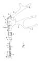
- FIG. 1is an exploded elevation view, partly in section, of a laparoscopic instrument assembly in accordance with one embodiment of the present invention
- FIG. 2is an elevation view, partly in section, of portions of the shaft and body of the assembly of FIG. 1, showing the sheath detent mechanism in further detail;
- FIG. 3is an exploded elevation view of the collet of FIGS. 1 and 2, showing the detent member and radial bore;
- FIG. 4is an elevation view of the collet closer of FIGS. 1 and 2;
- FIG. 5is an elevation view, partly in section, of the portions of the shaft and body of a laparoscopic instrument assembly in accordance with another embodiment of the invention.
- FIG. 6is an exploded elevation view of the collet of FIG. 5, showing the detent member and radial bore;
- FIG. 7is an elevation view of the collet closer of FIG. 5 .
- the laparoscopic instrument assembly described hereinincludes a body and a shaft operably interconnecting the body to a surgical tip.
- the shaftincludes a tubular sheath and a rod movable within the sheath.
- One end of the shaftmay be operably connected to the tip for actuation of a surgical device on the tip.
- the instrument assemblymay be used with a separately provided surgical tip or, optionally, the assembly may include a removable or non-removable tip.
- the other end of the shaftis removably and operably connected to the body and the shaft rod is movable axially within the sheath for transmission to the tip surgical device of handle member manipulation by the operator.
- the bodyincludes a casing, manually manipulable tip control means, a collet, a collet closer, and at least one collet detent member.
- the sheathis removably secured within the body by the compressive action of the collet closer on the collet and collet detent member.
- the shaftmay be readily disassembled from the body and, if desired, the shaft and body may be sterilized and readily reassembled for reuse of the instrument. Alternatively, the shaft may be disposed of and the body reassembled with a fresh shaft.
- the rod and sheath of the shaftare inserted into the collet axial bore, and the rod is secured within the instrument body for movement within the sheath in response to manipulation of the tip actuating means of the body.
- the collet closeris tightened, forcing the collet detent member inward to engage the groove or depression in the sheath.
- the securing of both the rod and the sheath within the bodyprevents removal of the shaft from the body during use of the instrument.
- the collet closeris loosened, permitting disengagement of the detent member from the sheath groove or depression and, upon disengagement of the rod from the body, permitting removal of the shaft from the body.
- actuation of the surgical deviceis effected by movement of the tip control means within an axial bore through the body, and movement of the shaft rod within the sheath in response to the movement of the tip control means.
- the means for operably and removably attaching the tip control meanstypically includes a rod which moves within the bore through the body in response to manipulation of a handle as described below.
- this tip control rodis attached to the shaft rod by threads on the body end of the shaft rod which engage a threaded axial bore in one end of the tip control rod.
- the tip control rodalso includes an axial bore into its shaft end and at least one detent member, e.g., a ball, disposed in a radial bore through the tip control rod. This additional detent member is engageable with, e.g., a groove on the body end of the shaft rod, holding the shaft rod to the tip control rod.
- laparoscopic instrument assembly 10in accordance with one embodiment of the present invention includes body 12 and shaft 14 operably interconnecting body 12 and removable tip 16 .
- Removable tip 16may be provided as part of assembly 10 or, alternatively, may be obtained separately.
- Shaft 14includes tubular sheath 18 and rod 20 movable within sheath 18 .
- Tip end 22 of shaft 14is operably connected to tip 16 for actuation of surgical device 24 on tip 16 .
- Body 12includes, inter alia, casing 26 , collet closer 28 , tip actuating means 30 , and tip actuating rod 32 .
- Tip actuating means 30includes stationary handle 34 and finger-operable, movable handle 36 pivotally linked to stationary handle 34 .
- Tip actuating rod 32is linked to moveable handle 36 for sliding axial movement within axial bore 38 through casing 26 in response to pivotal movement of movable handle 36 .
- stationary handle 34 and movable handle 36include openings 34 a and 36 a shaped to receive fingers and thumb, respectively, of the operator for scissors-like manipulation of the instrument.
- sheath 18includes groove 40 at body end 42 and, when held within casing 26 , is coaxial with bore 38 of the casing. Sheath 18 is held in conventional manner within casing 26 using collet 44 , shown in further detail in FIG. 3, and collet closer 28 , shown in further detail in FIG. 4 .
- Collet closer 28includes conical portion 46 and ring portion 48 .
- Collet 44includes conical portion 44 a and collet axial bore 50 , coaxial with axial bore 38 through casing 26 .
- Conical portion 44 a of collet 44includes at least one radial bore 54 within each of which a collet detent member 52 moves.
- Each collet radial bore 54is of a larger diameter at its outer end where it is open to an internal surface of collet closer conical portion 46 , and is of a smaller diameter at its inner end where it is open to collet axial bore 50 .
- detent member 52When collet closer 28 is tightened about collet 44 by turning ring portion 48 , detent member 52 is forced inwardly by the internal surface of collet closer conical portion 46 , partially enters collet axial bore 50 , and engages sheath groove 40 to hold sheath 18 firmly within body 12 . Detent member 52 is held in groove 40 by the close fit of the collet closer conical portion about the collet. on loosening of collet closer 28 and collet 44 , pulling of sheath 18 away from body 12 moves a wall of sheath groove 40 against detent member 52 , moving the detent member outwardly within collet radial groove 54 and releasing sheath 18 from body 12 .
- Each collet detent member 52is shown in the Figures as a ball.
- detent members 52may be any shape and size which will (a) permit only partial entry of each collet detent member 52 into collet axial bore 50 to engage groove 40 ; and (b) to be freely movable radially within its radial bore 54 in response to urging inwardly from the internal surface of conical portion 46 or to urging outwardly by a wall of groove 40 .
- the number of detent members 52 and bores 54is selected to optimize the gripping power of the detent members on sheath 18 .
- Rod 20is operably and removably connected to tip actuating rod 32 for axial movement of rod 20 within sheath 18 in response to movement of rod 32 within bore 38 .
- U.S. Pat. No. 5,810,879describes two embodiments of an instrument assembly with such connection.
- FIG. 2shows one embodiment in which body end 56 of shaft rod 20 removably and operably connected to tip actuating rod 32 of body 12 for transmission to the tip surgical device of manipulation by the operator of tip actuating means 30 .
- Shaft rod 20includes groove 58 at its body end 56 .
- Casing axial bore 38includes larger diameter portion 60 at the end of the bore near collet 44 and smaller diameter portion 62 nearer tip actuating means 30 .
- the diameter of narrower portion 62is selected for close sliding fit of tip actuating rod 32 therein.
- End 64 of rod 32includes axial bore 66 extending inwardly from end 64 and sized for close sliding fit of rod 20 therein.
- At least one radial bore 68is also formed in rod 32 to extend from the outer surface of rod 32 into and open to axial bore 66 .
- the position of radial bore 68is selected for registry of radial bore 68 with shaft rod groove 58 .
- Each radial bore 68has a larger diameter at the rod outer surface and a smaller diameter where it enters axial bore 66 .
- Each radial bore 68contains a detent member 70 therein for mating engagement of detent member 70 with groove 58 .
- the number of detent members 70is selected to optimize the gripping power of the detent members on rod 20 . Typically, from one to six detent members and radial bores are provided, with three the preferred number.
- Each detent member 70is shown in the Figures as a ball.
- detent members 70may be any shape and size which will (a) permit only partial entry of each detent member 70 into axial bore 66 ; (b) to be freely movable radially within its radial bore 68 in response to urging from the wall of narrow portion 62 of axial bore 32 or from a wall of groove 58 ; and (c) to extend beyond its radial bore 68 either into axial bore 66 to engage groove 58 or into wider portion 60 of the casing axial bore, but not into both.
- Each detent member 70engages groove 58 during actuation of tip surgical device 24 , preventing removal of rod 20 from axial bore 66 .
- sheath 18may be released from casing 26 as described above, and detent members 70 may be disengaged from groove 58 by separating handle members 34 and 36 (FIG. 1) sufficiently wide apart to drive rod 32 distally beyond its operating position, bringing radial bores 68 and detent members 70 in registry with larger portion 60 of the casing axial bore. In this position, pulling of shaft 14 forces the side wall of groove 58 against detent members 70 , forcing the detent members out of groove 58 and into larger portion 60 of the casing axial bore, permitting removal of shaft rod 20 from tip actuating rod 32 and separation of shaft 14 from body 12 .
- tip actuating rod 32is inserted into body 12 with sheath 18 in position within collet axial bore 50 and rod 20 inserted into axial bore 66 of tip actuating rod 32 with groove 58 in registry with radial bores 68 .
- Handles 34 and 36then may be brought closer together, drawing rod 32 closer to the handles.
- Narrower portion 62 of the casing axial borethen forces detent members 70 out of larger portion 60 of the casing axial and into groove 58 , locking rod 20 to rod 32 .
- Detent membersare held in groove 50 by the close sliding fit of rod 32 within narrower portion 48 of axial bore 34 .
- Collet closer 28is used as described above to tighten collet 38 against sheath 18 and to force detent member 52 into groove 40 .
- removable tip 16is attached to distal end 22 of shaft 18 in known manner, and surgical device 24 , e.g., cutting means or forceps, is actuated by scissor-like movement of handles 34 and 36 , which effects axial movement of rod 32 within the casing axial bore. Axial movement of rod 32 effects axial movement of rod 20 within and relative to sheath 18 , which actuates surgical device 24 of tip 16 in known manner.
- shaft 14may be provided without a tip, or a removable or non-removable tip may be provided as part of the shaft.
- FIG. 5shows an alternate embodiment if the laparoscopic instrument assembly. Like features to those shown in FIGS. 1-4 are indicated by the same reference numerals.
- FIG. 5shows in detail an alternate detent mechanism for operably and removably attaching the shaft rod to the tip actuating rod. Sheath 18 of shaft 14 a is attached to casing 26 a as described above. Body end 56 a of rod 20 a includes external threads 72 for mating engagement with internal threads 74 in axial bore 66 a in rod 32 a . Thus, body end 56 a of rod 20 a may be attached to end 64 a of rod 32 a by screwing threads 72 into threads 74 .
- rod 32 ais provided with slot 76 .
- Pin 78extends through slot 76 and is held in place within casing 26 a in conventional manner.
- casing 26 amay include casing sheath 80 with opposing radial bores 82 a and 82 b to receive and hold in place pin 78 .
- the relative sizes of slot 76 and pin 78are selected to permit free axial movement of rod 32 a within a range sufficient to manipulate a tip surgical device attached to shaft 14 a . Rotational movement of rod 32 a within the casing, however, is prevented by pin 78 .
- FIGS. 6 and 7show collet 44 and collet closer 28 a of FIG. 5, which are particularly suited to a smaller instrument than is shown in FIG. 1 .
- the instrument design shown in FIG. 1is preferred for instruments having a shaft diameter of 1-4 mm, while the design shown in FIG. 5 is preferred for those having a shaft diameter of 3-10 mm.
- Collet 44 of FIG. 6is of the same design as collet 44 of FIG. 3 .
- conical portion 46 a of collet closer 28 aincludes grooved surface 48 a .
- Grooved surface 48 aserves the same purpose as ring 48 of collet closer 28 of FIG. 4, that is turning the collet closer for assembly and disassembly of the instrument.
- This design of the collet closerallows for the addition of grooved grip ring 84 to body 12 , providing a firmer grip for the operator to hold and manipulate the smaller instrument.
- the invention described hereinpresents to the art a novel, improved laparoscopic instrument assembly having a removable and replaceable or disposable shaft, with or without a tip.
- the assemblyis simply and economically fabricated and the sheath portion of the shaft is readily and more securely held within the body of the assembly during operation of the instrument.
Landscapes
- Health & Medical Sciences (AREA)
- Surgery (AREA)
- Life Sciences & Earth Sciences (AREA)
- Biomedical Technology (AREA)
- Nuclear Medicine, Radiotherapy & Molecular Imaging (AREA)
- Engineering & Computer Science (AREA)
- Ophthalmology & Optometry (AREA)
- Heart & Thoracic Surgery (AREA)
- Medical Informatics (AREA)
- Molecular Biology (AREA)
- Animal Behavior & Ethology (AREA)
- General Health & Medical Sciences (AREA)
- Public Health (AREA)
- Veterinary Medicine (AREA)
- Surgical Instruments (AREA)
Abstract
Description
Claims (12)
Priority Applications (1)
| Application Number | Priority Date | Filing Date | Title |
|---|---|---|---|
| US09/536,553US6595984B1 (en) | 2000-03-28 | 2000-03-28 | Laparoscopic instrument with a detachable tip |
Applications Claiming Priority (1)
| Application Number | Priority Date | Filing Date | Title |
|---|---|---|---|
| US09/536,553US6595984B1 (en) | 2000-03-28 | 2000-03-28 | Laparoscopic instrument with a detachable tip |
Publications (1)
| Publication Number | Publication Date |
|---|---|
| US6595984B1true US6595984B1 (en) | 2003-07-22 |
Family
ID=24138976
Family Applications (1)
| Application Number | Title | Priority Date | Filing Date |
|---|---|---|---|
| US09/536,553Expired - LifetimeUS6595984B1 (en) | 2000-03-28 | 2000-03-28 | Laparoscopic instrument with a detachable tip |
Country Status (1)
| Country | Link |
|---|---|
| US (1) | US6595984B1 (en) |
Cited By (40)
| Publication number | Priority date | Publication date | Assignee | Title |
|---|---|---|---|---|
| US20030097146A1 (en)* | 2001-11-19 | 2003-05-22 | Scimed Life Systems, Inc. | Endoscopic surgical instrument |
| US20060161190A1 (en)* | 2005-01-19 | 2006-07-20 | Gadberry Donald L | Disposable laparoscopic instrument |
| US7101383B1 (en) | 2003-11-26 | 2006-09-05 | Van Ess Lester J | Laparoscopic instrument and method for its use |
| US20070129605A1 (en)* | 2004-02-05 | 2007-06-07 | Polydiagnost Gmbh | Endoscope comprising a flexible probe |
| US20080021278A1 (en)* | 2006-07-24 | 2008-01-24 | Leonard Robert F | Surgical device with removable end effector |
| US20090069842A1 (en)* | 2007-09-11 | 2009-03-12 | Woojin Lee | Surgical instrument |
| US20090281561A1 (en)* | 2008-05-09 | 2009-11-12 | Applied Medical Resources Corporation | Laparoscopic scissors |
| US7736374B2 (en) | 2004-05-07 | 2010-06-15 | Usgi Medical, Inc. | Tissue manipulation and securement system |
| US20100268268A1 (en)* | 2009-04-17 | 2010-10-21 | Uwe Bacher | Medical Instrument With A Rotatable Detent |
| US20110087266A1 (en)* | 2009-10-09 | 2011-04-14 | Conlon Sean P | Loader for exchanging end effectors in vivo |
| US20110087267A1 (en)* | 2009-10-09 | 2011-04-14 | Spivey James T | Method for exchanging end effectors in vivo |
| US20110087265A1 (en)* | 2009-10-09 | 2011-04-14 | Nobis Rudolph H | Laparoscopic instrument with attachable end effector |
| US20110245812A1 (en)* | 2010-04-01 | 2011-10-06 | Martin Blocher | Medical instrument for microinvasive surgical interventions |
| US20110306952A1 (en)* | 2010-06-10 | 2011-12-15 | Carefusion 2200, Inc. | Surgical device with reusable handle |
| EP2471473A1 (en)* | 2010-12-29 | 2012-07-04 | Consorcio para la Gestion del Centro de Cirugia de Minima Invasion | Apparatus for laparoscopic surgery |
| US8216252B2 (en) | 2004-05-07 | 2012-07-10 | Usgi Medical, Inc. | Tissue manipulation and securement system |
| US8257394B2 (en) | 2004-05-07 | 2012-09-04 | Usgi Medical, Inc. | Apparatus and methods for positioning and securing anchors |
| US20120253330A1 (en)* | 2009-12-23 | 2012-10-04 | Joimax GNBH | Surgical instrument for detachably connecting a handpiece to a surgical tool |
| US8298291B2 (en) | 2005-05-26 | 2012-10-30 | Usgi Medical, Inc. | Methods and apparatus for securing and deploying tissue anchors |
| US20120289773A1 (en)* | 2011-05-12 | 2012-11-15 | Microline Surgical, Inc. | Connector for a laparoscopic surgical system |
| US8444657B2 (en) | 2004-05-07 | 2013-05-21 | Usgi Medical, Inc. | Apparatus and methods for rapid deployment of tissue anchors |
| US8523893B2 (en) | 2010-09-30 | 2013-09-03 | Applied Medical Resources Corporation | Laparoscopic scissors |
| US8726909B2 (en) | 2006-01-27 | 2014-05-20 | Usgi Medical, Inc. | Methods and apparatus for revision of obesity procedures |
| CN103845112A (en)* | 2012-12-05 | 2014-06-11 | 涂名超 | Multi-degree-of-freedom execution machinery for laparoscopic minimally invasive surgery |
| US8764735B2 (en) | 2007-03-30 | 2014-07-01 | Ethicon Endo-Surgery, Inc. | Detachable end effectors |
| US20140243868A1 (en)* | 2013-02-27 | 2014-08-28 | Ethicon Endo-Surgery, Inc. | Percutaneous Instrument with Collet Locking Mechanisms |
| US8926634B2 (en) | 2004-05-07 | 2015-01-06 | Usgi Medical, Inc. | Apparatus and methods for manipulating and securing tissue |
| US9125681B2 (en) | 2012-09-26 | 2015-09-08 | Ethicon Endo-Surgery, Inc. | Detachable end effector and loader |
| US9585651B2 (en) | 2005-05-26 | 2017-03-07 | Usgi Medical, Inc. | Methods and apparatus for securing and deploying tissue anchors |
| US9814515B2 (en) | 2010-10-01 | 2017-11-14 | Microline Surgical, Inc. | Laparoscopic medical device with de-mateable tip |
| US10251636B2 (en) | 2015-09-24 | 2019-04-09 | Ethicon Llc | Devices and methods for cleaning a surgical device |
| US10265130B2 (en) | 2015-12-11 | 2019-04-23 | Ethicon Llc | Systems, devices, and methods for coupling end effectors to surgical devices and loading devices |
| US10314565B2 (en) | 2015-08-26 | 2019-06-11 | Ethicon Llc | Surgical device having actuator biasing and locking features |
| US10335196B2 (en) | 2015-08-31 | 2019-07-02 | Ethicon Llc | Surgical instrument having a stop guard |
| US10675009B2 (en) | 2015-11-03 | 2020-06-09 | Ethicon Llc | Multi-head repository for use with a surgical device |
| US10702257B2 (en) | 2015-09-29 | 2020-07-07 | Ethicon Llc | Positioning device for use with surgical instruments |
| US10912543B2 (en) | 2015-11-03 | 2021-02-09 | Ethicon Llc | Surgical end effector loading device and trocar integration |
| US10939909B2 (en) | 2012-12-13 | 2021-03-09 | Ethicon Llc | Circular needle applier with articulating and rotating shaft |
| US10993764B1 (en) | 2020-01-14 | 2021-05-04 | Microline Surgical, Inc. | Insulating grips for minimally invasive surgical instruments |
| US20230011670A1 (en)* | 2019-12-18 | 2023-01-12 | The Regents Of The University Of California | Rapid exchange endoscope system |
Citations (15)
| Publication number | Priority date | Publication date | Assignee | Title |
|---|---|---|---|---|
| US3574374A (en)* | 1969-01-16 | 1971-04-13 | Orthopedic Equipment Co | Surgical instrument |
| US4679556A (en)* | 1986-04-16 | 1987-07-14 | Shiley Inc. | Releasable holder and method of use |
| US4896986A (en)* | 1986-10-08 | 1990-01-30 | Olympus Optical Co, Ltd. | Endoscope connecting apparatus |
| US5222956A (en)* | 1992-07-06 | 1993-06-29 | Altair Instruments, Inc. | Surgical drill collet mechanism and bur |
| US5265343A (en)* | 1992-01-27 | 1993-11-30 | Hall Surgical, Division Of Zimmer, Inc. | Blade collet |
| US5358508A (en)* | 1993-09-15 | 1994-10-25 | Eric Cobb | Laparoscopic device |
| US5490683A (en)* | 1994-07-27 | 1996-02-13 | Mednext Inc. | Tool shaft coupler |
| US5578052A (en)* | 1992-10-27 | 1996-11-26 | Koros; Tibor | Insulated laparoscopic grasper with removable shaft |
| US5609603A (en)* | 1994-12-13 | 1997-03-11 | Hall Surgical Div. Of Zimmer Inc. | Surgical cutting device with safety interlock |
| US5741084A (en)* | 1995-03-27 | 1998-04-21 | Del Rio; Eddy H. | Wear compensating axial connection |
| US5782836A (en)* | 1996-07-30 | 1998-07-21 | Midas Rex Pneumatic Tools, Inc. | Resecting tool for magnetic field environment |
| US5810879A (en)* | 1997-02-27 | 1998-09-22 | Microline, Inc. | Laparoscopic instrument |
| US5989257A (en)* | 1998-03-11 | 1999-11-23 | Midas Rex L.P. | Redundant safety lock mechanism |
| US6113586A (en)* | 1998-01-16 | 2000-09-05 | Asahi Kogaku Kabushiki Kaisha | Joint mechanism for endoscopic treatment instrument, and endoscopic treatment system using that mechanism |
| US6209886B1 (en)* | 1999-04-30 | 2001-04-03 | Medtronic, Inc. | Resecting tool with independent variable axial extension for tool implements and guide sleeves |
- 2000
- 2000-03-28USUS09/536,553patent/US6595984B1/ennot_activeExpired - Lifetime
Patent Citations (15)
| Publication number | Priority date | Publication date | Assignee | Title |
|---|---|---|---|---|
| US3574374A (en)* | 1969-01-16 | 1971-04-13 | Orthopedic Equipment Co | Surgical instrument |
| US4679556A (en)* | 1986-04-16 | 1987-07-14 | Shiley Inc. | Releasable holder and method of use |
| US4896986A (en)* | 1986-10-08 | 1990-01-30 | Olympus Optical Co, Ltd. | Endoscope connecting apparatus |
| US5265343A (en)* | 1992-01-27 | 1993-11-30 | Hall Surgical, Division Of Zimmer, Inc. | Blade collet |
| US5222956A (en)* | 1992-07-06 | 1993-06-29 | Altair Instruments, Inc. | Surgical drill collet mechanism and bur |
| US5578052A (en)* | 1992-10-27 | 1996-11-26 | Koros; Tibor | Insulated laparoscopic grasper with removable shaft |
| US5358508A (en)* | 1993-09-15 | 1994-10-25 | Eric Cobb | Laparoscopic device |
| US5490683A (en)* | 1994-07-27 | 1996-02-13 | Mednext Inc. | Tool shaft coupler |
| US5609603A (en)* | 1994-12-13 | 1997-03-11 | Hall Surgical Div. Of Zimmer Inc. | Surgical cutting device with safety interlock |
| US5741084A (en)* | 1995-03-27 | 1998-04-21 | Del Rio; Eddy H. | Wear compensating axial connection |
| US5782836A (en)* | 1996-07-30 | 1998-07-21 | Midas Rex Pneumatic Tools, Inc. | Resecting tool for magnetic field environment |
| US5810879A (en)* | 1997-02-27 | 1998-09-22 | Microline, Inc. | Laparoscopic instrument |
| US6113586A (en)* | 1998-01-16 | 2000-09-05 | Asahi Kogaku Kabushiki Kaisha | Joint mechanism for endoscopic treatment instrument, and endoscopic treatment system using that mechanism |
| US5989257A (en)* | 1998-03-11 | 1999-11-23 | Midas Rex L.P. | Redundant safety lock mechanism |
| US6209886B1 (en)* | 1999-04-30 | 2001-04-03 | Medtronic, Inc. | Resecting tool with independent variable axial extension for tool implements and guide sleeves |
Cited By (69)
| Publication number | Priority date | Publication date | Assignee | Title |
|---|---|---|---|---|
| US20050033354A1 (en)* | 2001-11-19 | 2005-02-10 | Scimed Life Systems, Inc. | Endoscopic surgical instrument |
| US20030097146A1 (en)* | 2001-11-19 | 2003-05-22 | Scimed Life Systems, Inc. | Endoscopic surgical instrument |
| US7101383B1 (en) | 2003-11-26 | 2006-09-05 | Van Ess Lester J | Laparoscopic instrument and method for its use |
| US8333691B2 (en)* | 2004-02-05 | 2012-12-18 | Polydiagnost Gmbh | Endoscope comprising a flexible probe |
| US20070129605A1 (en)* | 2004-02-05 | 2007-06-07 | Polydiagnost Gmbh | Endoscope comprising a flexible probe |
| US8926634B2 (en) | 2004-05-07 | 2015-01-06 | Usgi Medical, Inc. | Apparatus and methods for manipulating and securing tissue |
| US8257394B2 (en) | 2004-05-07 | 2012-09-04 | Usgi Medical, Inc. | Apparatus and methods for positioning and securing anchors |
| US8216252B2 (en) | 2004-05-07 | 2012-07-10 | Usgi Medical, Inc. | Tissue manipulation and securement system |
| US8444657B2 (en) | 2004-05-07 | 2013-05-21 | Usgi Medical, Inc. | Apparatus and methods for rapid deployment of tissue anchors |
| US7736374B2 (en) | 2004-05-07 | 2010-06-15 | Usgi Medical, Inc. | Tissue manipulation and securement system |
| US8828027B2 (en) | 2004-05-07 | 2014-09-09 | U.S.G.I. Medical, Inc. | Tissue manipulation and securement system |
| US20060161190A1 (en)* | 2005-01-19 | 2006-07-20 | Gadberry Donald L | Disposable laparoscopic instrument |
| US8298291B2 (en) | 2005-05-26 | 2012-10-30 | Usgi Medical, Inc. | Methods and apparatus for securing and deploying tissue anchors |
| US9585651B2 (en) | 2005-05-26 | 2017-03-07 | Usgi Medical, Inc. | Methods and apparatus for securing and deploying tissue anchors |
| US8726909B2 (en) | 2006-01-27 | 2014-05-20 | Usgi Medical, Inc. | Methods and apparatus for revision of obesity procedures |
| US20080021278A1 (en)* | 2006-07-24 | 2008-01-24 | Leonard Robert F | Surgical device with removable end effector |
| US8764735B2 (en) | 2007-03-30 | 2014-07-01 | Ethicon Endo-Surgery, Inc. | Detachable end effectors |
| US10194931B2 (en) | 2007-03-30 | 2019-02-05 | Ethicon Endo-Surgery, Inc. | Detachable end effectors |
| US9662132B2 (en) | 2007-03-30 | 2017-05-30 | Ethicon Endo-Surgery, Inc. | Detachable end effectors |
| US20090069842A1 (en)* | 2007-09-11 | 2009-03-12 | Woojin Lee | Surgical instrument |
| WO2009035508A1 (en)* | 2007-09-11 | 2009-03-19 | Cambridge Endoscopic Devices, Inc. | Surgical instrument |
| US8257386B2 (en) | 2007-09-11 | 2012-09-04 | Cambridge Endoscopic Devices, Inc. | Surgical instrument |
| US8518070B2 (en) | 2008-05-09 | 2013-08-27 | Applied Medical Resources Corporation | Laparoscopic scissors |
| US9179929B2 (en) | 2008-05-09 | 2015-11-10 | Applied Medical Resources Corporation | Laparoscopic scissors |
| US9743945B2 (en) | 2008-05-09 | 2017-08-29 | Applied Medical Resources Corporation | Laparoscopic scissors |
| US8277475B2 (en) | 2008-05-09 | 2012-10-02 | Applied Medical Resources Corporation | Laparoscopic scissors |
| US20090281561A1 (en)* | 2008-05-09 | 2009-11-12 | Applied Medical Resources Corporation | Laparoscopic scissors |
| US8721670B2 (en) | 2008-05-09 | 2014-05-13 | Applied Medical Resources Corporation | Laparoscopic scissors |
| US8398620B2 (en)* | 2009-04-17 | 2013-03-19 | Karl Storz Gmbh & Co. Kg | Medical instrument with a rotatable detent |
| US20100268268A1 (en)* | 2009-04-17 | 2010-10-21 | Uwe Bacher | Medical Instrument With A Rotatable Detent |
| US10143454B2 (en) | 2009-10-09 | 2018-12-04 | Ethicon Llc | Loader for exchanging end effectors in vivo |
| US9186203B2 (en) | 2009-10-09 | 2015-11-17 | Ethicon Endo-Surgery, Inc. | Method for exchanging end effectors In Vivo |
| US20110087266A1 (en)* | 2009-10-09 | 2011-04-14 | Conlon Sean P | Loader for exchanging end effectors in vivo |
| US20110087267A1 (en)* | 2009-10-09 | 2011-04-14 | Spivey James T | Method for exchanging end effectors in vivo |
| US9295485B2 (en) | 2009-10-09 | 2016-03-29 | Ethicon Endo-Surgery, Inc. | Loader for exchanging end effectors in vivo |
| US20110087265A1 (en)* | 2009-10-09 | 2011-04-14 | Nobis Rudolph H | Laparoscopic instrument with attachable end effector |
| US9101369B2 (en)* | 2009-12-23 | 2015-08-11 | Joimax Gmbh | Surgical instrument for detachably connecting a handpiece to a surgical tool |
| US20120253330A1 (en)* | 2009-12-23 | 2012-10-04 | Joimax GNBH | Surgical instrument for detachably connecting a handpiece to a surgical tool |
| US10390820B2 (en)* | 2010-04-01 | 2019-08-27 | Karl Storz Se & Co. Kg | Medical instrument for microinvasive surgical interventions |
| US20110245812A1 (en)* | 2010-04-01 | 2011-10-06 | Martin Blocher | Medical instrument for microinvasive surgical interventions |
| AU2011264541B2 (en)* | 2010-06-10 | 2015-04-02 | Steris Corporation | Surgical device with reusable handle |
| US8956341B2 (en)* | 2010-06-10 | 2015-02-17 | Carefusion 2200, Inc. | Surgical device with reusable handle |
| US20110306952A1 (en)* | 2010-06-10 | 2011-12-15 | Carefusion 2200, Inc. | Surgical device with reusable handle |
| EP2579790B1 (en)* | 2010-06-10 | 2016-12-21 | CareFusion 2200 Inc. | Surgical device with reusable handle |
| US8523893B2 (en) | 2010-09-30 | 2013-09-03 | Applied Medical Resources Corporation | Laparoscopic scissors |
| US9814515B2 (en) | 2010-10-01 | 2017-11-14 | Microline Surgical, Inc. | Laparoscopic medical device with de-mateable tip |
| EP2471473A1 (en)* | 2010-12-29 | 2012-07-04 | Consorcio para la Gestion del Centro de Cirugia de Minima Invasion | Apparatus for laparoscopic surgery |
| US20120289773A1 (en)* | 2011-05-12 | 2012-11-15 | Microline Surgical, Inc. | Connector for a laparoscopic surgical system |
| US9326785B2 (en)* | 2011-05-12 | 2016-05-03 | Microline Surgical, Inc. | Connector for a laparoscopic surgical system |
| US9526516B2 (en) | 2012-09-26 | 2016-12-27 | Ethicon Endo-Surgery, Llc | Detachable end effector and loader |
| US9125681B2 (en) | 2012-09-26 | 2015-09-08 | Ethicon Endo-Surgery, Inc. | Detachable end effector and loader |
| CN103845112A (en)* | 2012-12-05 | 2014-06-11 | 涂名超 | Multi-degree-of-freedom execution machinery for laparoscopic minimally invasive surgery |
| CN103845112B (en)* | 2012-12-05 | 2018-03-27 | 展爱杰 | Laparoscope Minimally Invasive Surgery performs apparatus with multiple degrees of freedom |
| US10939909B2 (en) | 2012-12-13 | 2021-03-09 | Ethicon Llc | Circular needle applier with articulating and rotating shaft |
| US20140243868A1 (en)* | 2013-02-27 | 2014-08-28 | Ethicon Endo-Surgery, Inc. | Percutaneous Instrument with Collet Locking Mechanisms |
| US9451937B2 (en)* | 2013-02-27 | 2016-09-27 | Ethicon Endo-Surgery, Llc | Percutaneous instrument with collet locking mechanisms |
| US10314565B2 (en) | 2015-08-26 | 2019-06-11 | Ethicon Llc | Surgical device having actuator biasing and locking features |
| US10342520B2 (en) | 2015-08-26 | 2019-07-09 | Ethicon Llc | Articulating surgical devices and loaders having stabilizing features |
| US10335196B2 (en) | 2015-08-31 | 2019-07-02 | Ethicon Llc | Surgical instrument having a stop guard |
| US10251636B2 (en) | 2015-09-24 | 2019-04-09 | Ethicon Llc | Devices and methods for cleaning a surgical device |
| US10702257B2 (en) | 2015-09-29 | 2020-07-07 | Ethicon Llc | Positioning device for use with surgical instruments |
| US10675009B2 (en) | 2015-11-03 | 2020-06-09 | Ethicon Llc | Multi-head repository for use with a surgical device |
| US10912543B2 (en) | 2015-11-03 | 2021-02-09 | Ethicon Llc | Surgical end effector loading device and trocar integration |
| US10265130B2 (en) | 2015-12-11 | 2019-04-23 | Ethicon Llc | Systems, devices, and methods for coupling end effectors to surgical devices and loading devices |
| US20230011670A1 (en)* | 2019-12-18 | 2023-01-12 | The Regents Of The University Of California | Rapid exchange endoscope system |
| US10993764B1 (en) | 2020-01-14 | 2021-05-04 | Microline Surgical, Inc. | Insulating grips for minimally invasive surgical instruments |
| US11197712B2 (en) | 2020-01-14 | 2021-12-14 | Microline Surgical, Inc. | Insulating grips for minimally invasive surgical instruments |
| US11819261B2 (en) | 2020-01-14 | 2023-11-21 | Microline Surgical, Inc. | Insulating grips for minimally invasive surgical instruments |
| US12318128B2 (en) | 2020-01-14 | 2025-06-03 | Microline Surgical, Inc. | Insulating grips for minimally invasive surgical instruments |
Similar Documents
| Publication | Publication Date | Title |
|---|---|---|
| US6595984B1 (en) | Laparoscopic instrument with a detachable tip | |
| US5810879A (en) | Laparoscopic instrument | |
| US5507774A (en) | Surgical instrument capable of disassembly | |
| US5336238A (en) | Surgical instrument capable of disassembly | |
| US6007560A (en) | Biopsy forceps having detachable handle and distal jaws | |
| US5782748A (en) | Endoscopic surgical instruments having detachable proximal and distal portions | |
| US6077290A (en) | Endoscopic instrument with removable front end | |
| AU733633B2 (en) | Surgical instrument | |
| JP3911068B2 (en) | Joint motion transmission mechanism for surgical instruments | |
| US8221449B2 (en) | Surgical instrument with removable shaft apparatus and method | |
| US5454378A (en) | Biopsy forceps having a detachable proximal handle and distal jaws | |
| US6673092B1 (en) | Medical forceps with two independently moveable jaw parts | |
| US20130310866A1 (en) | Surgical handpiece with a compact clutch | |
| US20110137116A1 (en) | Endoscopic Surgical Instrument With Color-Coded Working Parts | |
| US20040068280A1 (en) | Clamp having bendable shaft | |
| JPH06269460A (en) | Rotatable elbowed apparatus | |
| GB2466180A (en) | Mechanisms for connecting a handle to a surgical instrument | |
| CN115005931A (en) | Minimally invasive surgical instrument components and minimally invasive surgical instruments | |
| JP2000271134A (en) | Endoscopic forceps | |
| CN115670592B (en) | Surgical scissors | |
| US20240277369A1 (en) | Modular forceps | |
| US20230389907A1 (en) | Modular forceps |
Legal Events
| Date | Code | Title | Description |
|---|---|---|---|
| AS | Assignment | Owner name:MICROLINE, INC., MASSACHUSETTS Free format text:ASSIGNMENT OF ASSIGNORS INTEREST;ASSIGNOR:DEGUILLEBON, HENRY F.;REEL/FRAME:010650/0550 Effective date:20000303 | |
| STCF | Information on status: patent grant | Free format text:PATENTED CASE | |
| FEPP | Fee payment procedure | Free format text:PAT HOLDER NO LONGER CLAIMS SMALL ENTITY STATUS, ENTITY STATUS SET TO UNDISCOUNTED (ORIGINAL EVENT CODE: STOL); ENTITY STATUS OF PATENT OWNER: LARGE ENTITY | |
| AS | Assignment | Owner name:MICROLINE PENTAX INC., MASSACHUSETTS Free format text:MERGER;ASSIGNOR:MICROLINE, INC.;REEL/FRAME:016745/0655 Effective date:20050331 | |
| FEPP | Fee payment procedure | Free format text:PAYOR NUMBER ASSIGNED (ORIGINAL EVENT CODE: ASPN); ENTITY STATUS OF PATENT OWNER: LARGE ENTITY | |
| FPAY | Fee payment | Year of fee payment:4 | |
| AS | Assignment | Owner name:MICROLINE SURGICAL, INC., MASSACHUSETTS Free format text:CHANGE OF NAME;ASSIGNOR:MICROLINE PENTAX, INC.;REEL/FRAME:023292/0858 Effective date:20090814 | |
| FPAY | Fee payment | Year of fee payment:8 | |
| FPAY | Fee payment | Year of fee payment:12 |