US6595801B1 - Electrical connector with electrically isolated ESD and EMI shields - Google Patents
Electrical connector with electrically isolated ESD and EMI shieldsDownload PDFInfo
- Publication number
- US6595801B1 US6595801B1US08/866,395US86639597AUS6595801B1US 6595801 B1US6595801 B1US 6595801B1US 86639597 AUS86639597 AUS 86639597AUS 6595801 B1US6595801 B1US 6595801B1
- Authority
- US
- United States
- Prior art keywords
- shield
- connector
- dielectric housing
- electrical connector
- shielded electrical
- Prior art date
- Legal status (The legal status is an assumption and is not a legal conclusion. Google has not performed a legal analysis and makes no representation as to the accuracy of the status listed.)
- Expired - Fee Related, expires
Links
Images


Classifications
- H—ELECTRICITY
- H01—ELECTRIC ELEMENTS
- H01R—ELECTRICALLY-CONDUCTIVE CONNECTIONS; STRUCTURAL ASSOCIATIONS OF A PLURALITY OF MUTUALLY-INSULATED ELECTRICAL CONNECTING ELEMENTS; COUPLING DEVICES; CURRENT COLLECTORS
- H01R13/00—Details of coupling devices of the kinds covered by groups H01R12/70 or H01R24/00 - H01R33/00
- H01R13/648—Protective earth or shield arrangements on coupling devices, e.g. anti-static shielding
- H01R13/6485—Electrostatic discharge protection
- H—ELECTRICITY
- H01—ELECTRIC ELEMENTS
- H01R—ELECTRICALLY-CONDUCTIVE CONNECTIONS; STRUCTURAL ASSOCIATIONS OF A PLURALITY OF MUTUALLY-INSULATED ELECTRICAL CONNECTING ELEMENTS; COUPLING DEVICES; CURRENT COLLECTORS
- H01R13/00—Details of coupling devices of the kinds covered by groups H01R12/70 or H01R24/00 - H01R33/00
- H01R13/62—Means for facilitating engagement or disengagement of coupling parts or for holding them in engagement
- H01R13/627—Snap or like fastening
- H01R13/6275—Latching arms not integral with the housing
- H—ELECTRICITY
- H01—ELECTRIC ELEMENTS
- H01R—ELECTRICALLY-CONDUCTIVE CONNECTIONS; STRUCTURAL ASSOCIATIONS OF A PLURALITY OF MUTUALLY-INSULATED ELECTRICAL CONNECTING ELEMENTS; COUPLING DEVICES; CURRENT COLLECTORS
- H01R13/00—Details of coupling devices of the kinds covered by groups H01R12/70 or H01R24/00 - H01R33/00
- H01R13/648—Protective earth or shield arrangements on coupling devices, e.g. anti-static shielding
- H01R13/658—High frequency shielding arrangements, e.g. against EMI [Electro-Magnetic Interference] or EMP [Electro-Magnetic Pulse]
- H01R13/6581—Shield structure
- H01R13/6582—Shield structure with resilient means for engaging mating connector
- H—ELECTRICITY
- H01—ELECTRIC ELEMENTS
- H01R—ELECTRICALLY-CONDUCTIVE CONNECTIONS; STRUCTURAL ASSOCIATIONS OF A PLURALITY OF MUTUALLY-INSULATED ELECTRICAL CONNECTING ELEMENTS; COUPLING DEVICES; CURRENT COLLECTORS
- H01R13/00—Details of coupling devices of the kinds covered by groups H01R12/70 or H01R24/00 - H01R33/00
- H01R13/648—Protective earth or shield arrangements on coupling devices, e.g. anti-static shielding
- H01R13/658—High frequency shielding arrangements, e.g. against EMI [Electro-Magnetic Interference] or EMP [Electro-Magnetic Pulse]
- H01R13/6591—Specific features or arrangements of connection of shield to conductive members
- H01R13/6592—Specific features or arrangements of connection of shield to conductive members the conductive member being a shielded cable
Definitions
- This inventiongenerally relates to the art of electrical connectors and, particularly, to an electrical connector having ESD and EMI protection.
- Electrical connectorsare used in a wide variety of applications. Some connectors simply are used to transmit power from a power source to an appropriate appliance. Other electrical connectors are used to interconnect signal transmission lines to printed circuit boards, other electronic devices or to other complementary connectors. The transmission lines transmit signals through a plurality of conductors which, preferably, are physically separated and electromagnetically isolated along their length. Hybrid connectors are known in which both power and signals and/or data are transmitted through the connector interface.
- Some electrical connectorsalso employ various types of shield structures, ground structures or the like to protect or to electrically interact with the transmission lines and their terminals within the connectors.
- some connectorsare provided with shield structures to protect against electrostatic discharges (ESD) which are generated when the connector comes into contact with another conductive body which may be a complementary mating connector.
- ESDelectrostatic discharges
- the ESD shieldis used to dissipate static charges.
- Connectorsalso may have shield structures to protect against electromagnetic interference (EMI).
- EMIelectromagnetic interference
- the EMI shieldprotects the electrical circuitry from externally generated radiated emissions as well as preventing electromagnetic interference from radiating outwardly of the connector.
- ESD and EMI shieldsare provided by stamped and formed conductive sheet metal components which conventionally surround the connector housing.
- the metal shieldmay be a one-piece structure or a multi-part structure with the multiple parts of the shield being in positive engagement.
- Such shielding structuresoften act as both an ESD shield as well as an EMI shield.
- a pair of metal shieldsmay be separated from each other by portions of the dielectric connector housing, but, in these instances, one of the shields is located substantially internally of the connector.
- a combo connectoris an electrical connector which incorporates the combination of both signal transmission lines/terminals and power lines/terminals in the single connector. If the ESD shield and the EMI shield in a combo connector are commoned to each other or are grounded to a common source, such as a printed circuit board, an electrical discharge from one of the power lines/terminals could damage the printed circuit board or even overload the circuitry.
- the ESD ground meansis electrically isolated from the EMI ground means for use in such electrical connectors as combination power and signal connectors, without the system being unduly complicated.
- the systemwould involve the standard components of the electrical connector without requiring additional extraneous grounding apparatus.
- the present inventionis directed to satisfying this need and solving the problems outlined above.
- An object, therefore, of the inventionis to provide an electrical connector with a new and improved shielding system wherein the ESD shield and the EMI shield are electrically isolated from each other.
- the electrical connectorincludes a dielectric housing having a forward mating end and a rearward end.
- a front ESD shieldis disposed about the exterior of at least a substantial portion of the forward mating end of the dielectric housing.
- a rear EMI shieldis disposed about the exterior of at least a substantial portion of the rearward end of the dielectric housing.
- the front ESD shieldis electrically isolated from the rear EMI shield by an outwardly projecting portion of the dielectric housing physically separating the shields. Therefore, no extraneous insulating components whatsoever are required.
- the forward mating end of the housingincludes a receptacle portion for receiving a plug portion of a complementary mating connector.
- the front ESD shieldis disposed about the receptacle portion, whereby the receptacle portion forms a dielectric barrier between the ESD shield and the plug portion of the complementary mating connector.
- the receptacle portionis generally rectangular, and the ESD shield includes a rectangular shroud surrounding the rectangular receptacle portion.
- the front ESD shieldincludes at least one retention portion for locking the shield to the outwardly projecting portion of the dielectric housing.
- the outwardly projecting portionis formed as a peripheral flange.
- the ESD shieldincludes at least one retention tab embracing the peripheral flange for fixing the ESD shield to the housing.
- the inventionis disclosed herein in a shielded electrical connector adapted for mounting on a printed circuit board and through an aperture in a conductive bracket.
- the front ESD shieldis adapted for engaging the conductive bracket about the aperture therein.
- the rear EMI shieldhas ground means adapted for engaging a ground circuit on the printed circuit board.
- the shielded electrical connectoris adapted for mating with a complementary mating connector which includes a peripheral metal shield.
- Complementary interengaging latch meansis provided between the peripheral shield of the mating connector and the dielectric housing of the shielded electrical connector.
- the complementary interengaging latch meansincludes a latch arm folded back from a forward end of the peripheral metal shield for engaging a latch member inside the forward mating end of the dielectric housing.
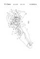
- FIG. 1is a perspective view of a connector assembly including a receptacle connector and a plug connector, the receptacle connector incorporating the concepts of the invention
- FIG. 2is a perspective view of the connector assembly taken 180° from the direction of FIG. 1;
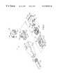
- FIG. 3is an exploded perspective view of the components of the receptacle connector
- FIG. 4is an exploded perspective view of the components of the plug connector
- FIG. 5is a top plan view of the connector assembly in assembled condition
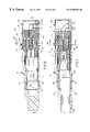
- FIG. 6is a vertical section taken generally along line 6 — 6 of FIG. 5;
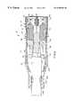
- FIG. 7is a vertical section taken generally along line 7 — 7 of FIG. 5;
- FIG. 8is a vertical section taken generally along line 8 — 8 of FIG. 5;
- FIG. 9is a horizontal section taken generally along line 9 — 9 of FIG. 8;
- FIG. 10is a vertical section taken generally along line 10 — 10 of FIG. 7 .
- an electrical connector assemblyis shown to include a receptacle connector, generally designated 14 , and a plug connector, generally designated 16 .
- Plug connector 16is insertable into receptacle connector 14 in the direction of arrow “A.
- Receptacle connector 14is adapted for mounting on the top of a printed circuit board 18 .
- the front end of the receptacle connectoris adapted for mounting through an aperture 20 in a conductive bracket 22 which may form part of a chassis with which the connector assembly is associated.
- receptacle connector 14generally includes a dielectric housing, generally designated 24 , which is molded of plastic material or the like.
- the dielectric housinghas a rectangular forward mating end 26 and a rearward end 28 with an outwardly projecting peripheral flange 30 therebetween.
- the housingalso has a forwardly projecting, internal mating portion 32 having laterally outwardly extending wing portions 32 a.
- Receptacle connector 14has a terminal array, generally designated 34 , for mounting in dielectric housing 24 .
- the terminal arrayincludes four signal female terminals 36 positionable into four terminal-receiving passages 38 in housing 24 in the direction of arrow “B” (FIG. 3 ).
- the terminal arrayincludes four blade-like power terminals 40 insertable into open grooves 42 on opposite sides of wings 32 a of mating portion 32 of the housing.
- Signal terminals 36have tail portions 36 a and power terminals 40 have tail portions 40 a for insertion into appropriate holes in printed circuit board 18 and for solder connection to circuit traces on the board and/or in the holes.
- Signal terminals 36are divided vertically by a ground plate 44 insertable into a vertical slot 46 in mating portion 32 of the housing. It can be seen in FIG. 3 that a horizontal slot 48 intersects vertical slot 46 to form a cross configuration.
- Receptacle connector 14includes a tail aligner, generally designated 50 , which has hooked latch arms 52 for snappingly assembling the tail aligner to the underside of dielectric housing 24 at the rearward end thereof.
- the tail alignerincludes four tail aligning holes 54 on each opposite side of a slotted partition 56 for receiving tail portions 36 a and 40 a of signal terminals 36 and power terminals 40 , respectively.
- Partition 56includes a vertical slot 56 a for receiving ground plate 44 .
- Receptacle connector 14includes a front ESD shield, generally designated 58 , which is positioned about the exterior of forward mating end 26 of dielectric housing 24 .
- Shield 58is a one-piece structure drawn of conductive sheet metal material. More particularly, the ESD shield includes a rectangular shroud 60 projecting forwardly of a generally planar peripheral flange 62 .
- Shroud 60is sized and shaped for positioning around rectangular forward mating end 26 of the dielectric housing and, flange 62 is adapted for abutting against the front face of peripheral flange 30 of the housing.
- a plurality of retention tabs 64are bent through notches 66 in housing flange 30 to embrace the flange and secure or fix front ESD shield 58 to the housing.
- Receptacle connector 14further includes a rear EMI shield, generally designated 68 .
- Shield 68is a one-piece structure stamped and formed of conductive sheet metal material.
- the rear EMI shieldis generally rectangular or box-shaped for positioning substantially entirely about rearward end 28 of dielectric housing 24 , i.e., about substantially the entire housing rearwardly of outwardly projecting peripheral flange 30 of the housing.
- EMI shield 68has a pair of retention tabs 68 a that wrap around a lower portion of housing 24 .
- Along each side wall 72 of the EMI shieldare a pair of tail portions 70 depending downwardly from the side walls as well as a fork lock 71 for insertion into appropriate mounting holes in printed circuit board 18 .
- Tails 70 and fork locks 71not only function as mounting posts for the connector, but they are electrically connected to ground circuit traces on the printed circuit board as by soldering to the ground traces on the board and/or in the mounting holes.
- rear EMI shield 68includes a inwardly bowed spring arms 74 stamped and formed out of side walls 72 and top wall 73 for engaging an external shield of plug connector 16 , as will be described hereinafter.
- front ESD shield 58which is positioned about the exterior of at least a substantial portion of forward mating end 26 of dielectric housing 24 operates to dissipate electrostatic discharges from mating plug connector 16 as well as any electrical discharges from the power terminals of the plug connector.
- the front ESD shieldwill also dissipate any electrical discharges from extraneous objects such as tools which are inappropriately inserted into receptacle connector 14 and which may engage power terminals 40 which are visible through the front of the connector as seen in FIG. 1 .
- the front ESD shieldextends through aperture 20 in conductive bracket 22 and is in full engagement with the bracket for dissipating charges thereto.
- the front ESD shield 58will also function as an EMI shield to a certain extent.
- Rear EMI shield 68is effective to protect the terminal interface area of terminal array 34 from externally emitted radiations as well as to prevent internal radiations from being emitted externally of the connector to other electrical components, such as adjacent components on printed circuit board 18 .
- the rear EMI shieldis disposed about the exterior of substantially the entire rearward end 28 of dielectric housing 24 rearwardly of flange 30 .
- Front ESD shield 58is electrically isolated from rear EMI shield 68 by outwardly projecting peripheral flange 30 of dielectric housing 24 .
- the dielectric flangephysically and electrically separates the two one-piece shields so that front ESD shield 58 can be grounded to conductive bracket 22 and rear EMI shield 68 can be independently grounded to printed circuit board 18 .
- the front edge of the rear shieldincludes rectangular recesses 75 . These recesses 75 are aligned with retention tabs 64 and ensure that the front and rear will not contact each other.
- the entire leading or front edge of front ESD shield 58could be designed so as not to extend as far towards flange 30 in which case the recesses could be eliminated.
- plug connector 16includes a dielectric housing, generally designated 76 , which includes a forward mating end 76 a and a rearward end 76 b .
- a dielectric housinggenerally designated 76 , which includes a forward mating end 76 a and a rearward end 76 b .
- Four signal terminals 78are mounted in the housing for electrical connection to signal terminals 36 of receptacle connector 14 .
- Four power terminals 80are mounted in the housing for electric connection to power terminals 40 of the receptacle connector.
- a ground plate 82horizontally separates the signal terminals and is inserted into slot 48 in mating portion 32 of the receptacle connector.
- Horizontal ground plate 82also is positioned into a slot 84 (FIG. 3) in vertical ground plate 44 of the receptacle connector to define a cross-shaped ground plate configuration.
- Plug connector 16has a shield structure which includes a generally rectangular, box-shaped shield 86 which is positionable over substantially the entire dielectric housing 76 .
- Shield 86is a one-piece structure stamped and formed of sheet metal material and includes a plurality of forwardly projecting positioning tabs 88 which are positioned in notches 90 of a peripheral flange 92 at the front mating end 76 a of dielectric housing 76 .
- the shield structure of plug connector 16also includes a rear outer shell having a top shell half 94 and a bottom shell half 96 .
- the shell halvesare stamped and formed of sheet metal material and have forwardly projecting retention hooks 98 which are positioned into retention slots 100 of shield 86 to secure the shell halves to the shield. Hooks 98 are rotated into slots 100 , as shell halves 94 and 96 are pivoted toward each other so that latch arms 102 of bottom shell half 96 snap into engagement with latch arms 104 of top shell half 96 to completely enclose the rearward end of dielectric housing 16 .
- Bottom shell half 96includes a crimping structure 106 for clamping onto the outside of an electrical cable 108 .
- Plug connector 16includes an insulative boot 110 which is overmolded about the rear end of shield 86 , about the entirety of shell halves 94 and 96 and about the interface area between cable 108 and the connector.
- the overmolded bootnot only forms an insulating layer about the rear of the connector, but the boot provides a strain relief for cable 108 .
- the bootstops short of the forward mating end 76 a of the dielectric housing to expose the front area of shield 86 .
- the bootalso has a cutout 112 at the front thereof for accommodating a spring latch arm 114 of shield 86 .
- shield 86is grounded through shell halves 94 and 96 to a ground braid 108 a which is included within cable 108 . Therefore, shield 86 can act both as an ESD shield as well as an EMI shield.
- FIGS. 5-10show considerable details of connector assembly 12 , including receptacle connector 14 and plug connector 16 , in a fully assembled condition. Details of the cable 108 and the interrelationship between the signal terminals, the power terminals and the cross-shaped ground plates 44 and 82 will not be described herein. If desirable or necessary, these details can be derived from copending application Ser. No. 08/783,418, filed Jan. 14, 1997, which is assigned to assignee of the present invention and which is incorporated herein by reference. Suffice it to say, FIGS. 5-9 clearly show how outwardly projecting peripheral flange 30 of dielectric housing 24 of receptacle connector 14 electrically isolates front ESD shield 58 from rear EMI shield 68 of the receptacle connector. FIG. 9 shows how spring arms 74 of rear EMI shield 68 of receptacle connector 14 engage the sides of shield 86 of plug connector 16 .
- FIG. 7shows that the dielectric housing of receptacle connector 14 includes an internal latch shoulder 116 for engaging spring latch arm 114 of plug connector 16 .
- latch arm 114is cantilevered rearwardly from a forward end of shield 86 of plug connector 16 . With shield 86 being stamped and formed of sheet metal material, the latch arm is folded back from the forward edge of the metal shield.
- the latch armincludes an enlarged head portion 114 a at the distal end thereof.
- the base of the cantilevered latch armalso is enlarged to define a pair of outwardly projecting, rearwardly facing latch shoulders 114 b .
- latch shoulders 114 b of the latch armactually are adapted for engaging a pair of the internal latch shoulders 116 on the inside of the dielectric housing at the forward mating end of receptacle connector 14 . It also can be seen in FIG. 7 how the enlarged distal end 114 a of the latch arm projects through cutout 112 in boot 110 so that an operator can depress the latch arm and disengage the complementary interengaging latch means provided by latch shoulders 114 b and 116 to unmate the connectors. Therefore, peripheral metal shield 86 of plug connector 16 remains isolated from either of the shields of receptacle connector 14 , because latch arm 114 of the plug connector interengages with the dielectric housing of the receptacle connector.
Landscapes
- Details Of Connecting Devices For Male And Female Coupling (AREA)
- Coupling Device And Connection With Printed Circuit (AREA)
Abstract
Description
This invention generally relates to the art of electrical connectors and, particularly, to an electrical connector having ESD and EMI protection.
Electrical connectors are used in a wide variety of applications. Some connectors simply are used to transmit power from a power source to an appropriate appliance. Other electrical connectors are used to interconnect signal transmission lines to printed circuit boards, other electronic devices or to other complementary connectors. The transmission lines transmit signals through a plurality of conductors which, preferably, are physically separated and electromagnetically isolated along their length. Hybrid connectors are known in which both power and signals and/or data are transmitted through the connector interface.
Some electrical connectors also employ various types of shield structures, ground structures or the like to protect or to electrically interact with the transmission lines and their terminals within the connectors. For instance, some connectors are provided with shield structures to protect against electrostatic discharges (ESD) which are generated when the connector comes into contact with another conductive body which may be a complementary mating connector. In essence, the ESD shield is used to dissipate static charges.
Connectors also may have shield structures to protect against electromagnetic interference (EMI). In essence, the EMI shield protects the electrical circuitry from externally generated radiated emissions as well as preventing electromagnetic interference from radiating outwardly of the connector.
Typically, ESD and EMI shields are provided by stamped and formed conductive sheet metal components which conventionally surround the connector housing. The metal shield may be a one-piece structure or a multi-part structure with the multiple parts of the shield being in positive engagement. Such shielding structures often act as both an ESD shield as well as an EMI shield. In some instances, a pair of metal shields may be separated from each other by portions of the dielectric connector housing, but, in these instances, one of the shields is located substantially internally of the connector.
Heretofore, the fact that a one-piece shield or a multi-part shield acted both as an ESD shield as well as an EMI shield did not make much difference, because the connectors were provided primarily for signal transmission purposes. In other words, the dissipation of minor static charges did not cause any problem with grounding the EMI shield, even grounding the shield to a circuit board to which the connector is attached.
However, with the advent of what are called “combo” electrical connectors, combined ESD and EMI shield have caused problems. A combo connector is an electrical connector which incorporates the combination of both signal transmission lines/terminals and power lines/terminals in the single connector. If the ESD shield and the EMI shield in a combo connector are commoned to each other or are grounded to a common source, such as a printed circuit board, an electrical discharge from one of the power lines/terminals could damage the printed circuit board or even overload the circuitry. There is a need for a simple grounding system to solve these problems, wherein the ESD ground means is electrically isolated from the EMI ground means for use in such electrical connectors as combination power and signal connectors, without the system being unduly complicated. Preferably, the system would involve the standard components of the electrical connector without requiring additional extraneous grounding apparatus. The present invention is directed to satisfying this need and solving the problems outlined above.
An object, therefore, of the invention is to provide an electrical connector with a new and improved shielding system wherein the ESD shield and the EMI shield are electrically isolated from each other.
In the exemplary embodiment of the invention, the electrical connector includes a dielectric housing having a forward mating end and a rearward end. A front ESD shield is disposed about the exterior of at least a substantial portion of the forward mating end of the dielectric housing. A rear EMI shield is disposed about the exterior of at least a substantial portion of the rearward end of the dielectric housing. The front ESD shield is electrically isolated from the rear EMI shield by an outwardly projecting portion of the dielectric housing physically separating the shields. Therefore, no extraneous insulating components whatsoever are required.
As disclosed herein, the forward mating end of the housing includes a receptacle portion for receiving a plug portion of a complementary mating connector. The front ESD shield is disposed about the receptacle portion, whereby the receptacle portion forms a dielectric barrier between the ESD shield and the plug portion of the complementary mating connector. As disclosed, the receptacle portion is generally rectangular, and the ESD shield includes a rectangular shroud surrounding the rectangular receptacle portion.
A feature of the invention is that the front ESD shield includes at least one retention portion for locking the shield to the outwardly projecting portion of the dielectric housing. In the preferred embodiment, the outwardly projecting portion is formed as a peripheral flange. The ESD shield includes at least one retention tab embracing the peripheral flange for fixing the ESD shield to the housing.
The invention is disclosed herein in a shielded electrical connector adapted for mounting on a printed circuit board and through an aperture in a conductive bracket. The front ESD shield is adapted for engaging the conductive bracket about the aperture therein. The rear EMI shield has ground means adapted for engaging a ground circuit on the printed circuit board.
The shielded electrical connector is adapted for mating with a complementary mating connector which includes a peripheral metal shield. Complementary interengaging latch means is provided between the peripheral shield of the mating connector and the dielectric housing of the shielded electrical connector. The complementary interengaging latch means includes a latch arm folded back from a forward end of the peripheral metal shield for engaging a latch member inside the forward mating end of the dielectric housing.
Other objects, features and advantages of the invention will be apparent from the following detailed description taken in connection with the accompanying drawings.
The features of this invention which are believed to be novel are set forth with particularity in the appended claims. The invention, together with its objects and the advantages thereof, may be best understood by reference to the following description taken in conjunction with the accompanying drawings, in which like reference numerals identify like elements in the figures and in which:
FIG. 1 is a perspective view of a connector assembly including a receptacle connector and a plug connector, the receptacle connector incorporating the concepts of the invention;
FIG. 2 is a perspective view of the connector assembly taken 180° from the direction of FIG. 1;
FIG. 3 is an exploded perspective view of the components of the receptacle connector;
FIG. 4 is an exploded perspective view of the components of the plug connector;
FIG. 5 is a top plan view of the connector assembly in assembled condition;
FIG. 6 is a vertical section taken generally alongline 6—6 of FIG. 5;
FIG. 7 is a vertical section taken generally along line7—7 of FIG. 5;
FIG. 8 is a vertical section taken generally along line8—8 of FIG. 5;
FIG. 9 is a horizontal section taken generally alongline 9—9 of FIG. 8; and
FIG. 10 is a vertical section taken generally alongline 10—10 of FIG.7.
Referring to the drawings in greater detail, and first to FIGS. 1 and 2, an electrical connector assembly, generally designated12, is shown to include a receptacle connector, generally designated14, and a plug connector, generally designated16.Plug connector 16 is insertable intoreceptacle connector 14 in the direction of arrow “A.Receptacle connector 14 is adapted for mounting on the top of a printedcircuit board 18. The front end of the receptacle connector is adapted for mounting through anaperture 20 in aconductive bracket 22 which may form part of a chassis with which the connector assembly is associated.
Referring to FIG. 3 in conjunction with FIGS. 1 and 2,receptacle connector 14 generally includes a dielectric housing, generally designated24, which is molded of plastic material or the like. The dielectric housing has a rectangularforward mating end 26 and arearward end 28 with an outwardly projectingperipheral flange 30 therebetween. The housing also has a forwardly projecting,internal mating portion 32 having laterally outwardly extending wing portions32a.
In function,front ESD shield 58 which is positioned about the exterior of at least a substantial portion of forward mating end26 ofdielectric housing 24 operates to dissipate electrostatic discharges frommating plug connector 16 as well as any electrical discharges from the power terminals of the plug connector. The front ESD shield will also dissipate any electrical discharges from extraneous objects such as tools which are inappropriately inserted intoreceptacle connector 14 and which may engagepower terminals 40 which are visible through the front of the connector as seen in FIG.1. The front ESD shield extends throughaperture 20 inconductive bracket 22 and is in full engagement with the bracket for dissipating charges thereto. Thefront ESD shield 58 will also function as an EMI shield to a certain extent.
In order to maximize the shielding provided byrear EMI shield 68 yet ensure that it is electrically isolated fromfront ESD shield 58, the front edge of the rear shield includes rectangular recesses75. These recesses75 are aligned withretention tabs 64 and ensure that the front and rear will not contact each other. In the alternative, the entire leading or front edge offront ESD shield 58 could be designed so as not to extend as far towardsflange 30 in which case the recesses could be eliminated.
Referring to FIG. 4 in conjunction with FIGS. 1 and 2, plugconnector 16 includes a dielectric housing, generally designated76, which includes a forward mating end76aand arearward end 76b. Foursignal terminals 78 are mounted in the housing for electrical connection to signalterminals 36 ofreceptacle connector 14. Fourpower terminals 80 are mounted in the housing for electric connection topower terminals 40 of the receptacle connector. Aground plate 82 horizontally separates the signal terminals and is inserted intoslot 48 inmating portion 32 of the receptacle connector.Horizontal ground plate 82 also is positioned into a slot84 (FIG. 3) invertical ground plate 44 of the receptacle connector to define a cross-shaped ground plate configuration.
The shield structure ofplug connector 16 also includes a rear outer shell having atop shell half 94 and abottom shell half 96. The shell halves are stamped and formed of sheet metal material and have forwardly projecting retention hooks98 which are positioned intoretention slots 100 ofshield 86 to secure the shell halves to the shield.Hooks 98 are rotated intoslots 100, as shell halves94 and96 are pivoted toward each other so thatlatch arms 102 ofbottom shell half 96 snap into engagement withlatch arms 104 oftop shell half 96 to completely enclose the rearward end ofdielectric housing 16.Bottom shell half 96 includes a crimpingstructure 106 for clamping onto the outside of anelectrical cable 108.
Inplug connector 16,shield 86 is grounded throughshell halves cable 108. Therefore, shield86 can act both as an ESD shield as well as an EMI shield.
FIGS. 5-10 show considerable details ofconnector assembly 12, includingreceptacle connector 14 and plugconnector 16, in a fully assembled condition. Details of thecable 108 and the interrelationship between the signal terminals, the power terminals and thecross-shaped ground plates peripheral flange 30 ofdielectric housing 24 ofreceptacle connector 14 electrically isolatesfront ESD shield 58 fromrear EMI shield 68 of the receptacle connector. FIG. 9 shows howspring arms 74 ofrear EMI shield 68 ofreceptacle connector 14 engage the sides ofshield 86 ofplug connector 16.
FIG. 7 shows that the dielectric housing ofreceptacle connector 14 includes aninternal latch shoulder 116 for engagingspring latch arm 114 ofplug connector 16. More particularly, as best seen in FIGS. 1,2 and4,latch arm 114 is cantilevered rearwardly from a forward end ofshield 86 ofplug connector 16. Withshield 86 being stamped and formed of sheet metal material, the latch arm is folded back from the forward edge of the metal shield. The latch arm includes an enlarged head portion114aat the distal end thereof. The base of the cantilevered latch arm also is enlarged to define a pair of outwardly projecting, rearwardly facing latch shoulders114b. Now, referring to FIG. 7, latch shoulders114bof the latch arm actually are adapted for engaging a pair of the internal latch shoulders116 on the inside of the dielectric housing at the forward mating end ofreceptacle connector 14. It also can be seen in FIG. 7 how the enlarged distal end114aof the latch arm projects throughcutout 112 inboot 110 so that an operator can depress the latch arm and disengage the complementary interengaging latch means provided bylatch shoulders 114b and 116 to unmate the connectors. Therefore,peripheral metal shield 86 ofplug connector 16 remains isolated from either of the shields ofreceptacle connector 14, becauselatch arm 114 of the plug connector interengages with the dielectric housing of the receptacle connector.
It will be understood that the invention may be embodied in other specific forms without departing from the spirit or central characteristics thereof. The present examples and embodiments, therefore, are to be considered in all respects as illustrative and not restrictive, and the invention is not to be limited to the details given herein.
Claims (26)
1. A shielded electrical connector, comprising:
a dielectric housing having a forward mating end and a rearward end;
a front ESD shield about the exterior of at least a substantial portion of the forward mating end of the dielectric housing;
a rear EMI shield about the exterior of at least a substantial portion of the rearward end of the dielectric housing; and
wherein the front ESD shield is electrically isolated from the rear EMI shield by an outwardly projecting portion of the dielectric housing physically separating the shields.
2. The shielded electrical connector ofclaim 1 wherein said forward mating end of the housing includes a receptacle portion for receiving a plug portion of a complementary mating connector, the front ESD shield being disposed about said receptacle portion, with the receptacle portion forming a dielectric barrier between the ESD shield and the plug portion of the complementary mating connector.
3. The shielded electrical connector ofclaim 2 wherein said receptacle portion is generally rectangular, and the ESD shield includes a rectangular shroud surrounding the rectangular receptacle portion.
4. The shielded electrical connector ofclaim 1 wherein said front ESD shield includes at least one retention portion for locking the shield to said outwardly projecting portion of the dielectric housing.
5. The shielded electrical connector ofclaim 1 wherein said outwardly projecting portion of the dielectric housing comprises a peripheral flange.
6. The shielded electrical connector ofclaim 5 wherein said front ESD shield includes at least one retention tab embracing said peripheral flange for fixing the ESD shield to the housing.
7. In combination with the shielded electrical connector ofclaim 1 , a complementary mating connector including a peripheral metal shield, and complementary interengaging latch means between the peripheral metal shield of the mating connector and the dielectric housing of the shielded electrical connector.
8. The combination ofclaim 7 wherein said complementary interengaging latch means comprises a latch member inside the forward mating end of the dielectric housing.
9. The combination ofclaim 7 wherein said complementary interengaging latch means comprises a latch arm folded back from a forward end of said peripheral metal shield.
10. The combination ofclaim 9 wherein said complementary interengaging latch means comprises a latch member inside the forward mating end of the dielectric housing.
11. A shielded electrical connector assembly, comprising:
a dielectric housing having a forward mating end and a rearward end;
a front ESD shield about the exterior of at least a substantial portion of the forward mating end of the dielectric housing, the front ESD shield being adapted for engaging an aperture in a conductive bracket;
a rear EMI shield about the exterior of at least a substantial portion of the rearward end of the dielectric housing, the rear EMI shield having ground means adapted for engaging a ground circuit on a printed circuit board; and
wherein the front ESD shield is electrically isolated from the rear EMI shield by an outwardly projecting portion of the dielectric housing physically separating the shields.
12. The shielded electrical connector ofclaim 11 wherein said forward mating end of the housing includes a receptacle portion for receiving a plug portion of a complementary mating connector, the front ESD shield being disposed about said receptacle portion, with the receptacle portion forming a dielectric barrier between the ESD shield and the plug portion of the complementary mating connector.
13. The shielded electrical connector ofclaim 12 wherein said receptacle portion and the surrounding ESD shield are sized for insertion through the aperture in the conductive bracket.
14. The shielded electrical connector ofclaim 13 wherein said receptacle portion is generally rectangular, and the ESD shield includes a rectangular shroud surrounding the rectangular receptacle portion.
15. The shielded electrical connector ofclaim 11 wherein said ground means comprises tails for connection to the ground circuit on the printed circuit board.
16. The shielded electrical connector ofclaim 11 wherein said front ESD shield includes at least one retention portion for locking the shield to said outwardly projecting portion of the dielectric housing.
17. The shielded electrical connector ofclaim 11 wherein said outwardly projecting portion of the dielectric housing comprises a peripheral flange.
18. The shielded electrical connector ofclaim 17 wherein said front ESD shield includes at least one retention tab embracing said peripheral flange for fixing the ESD shield to the housing.
19. In combination with the shielded electrical connector ofclaim 11 , a complementary mating connector including a peripheral metal shield, and complementary interengaging latch means between the peripheral metal shield of the mating connector and the dielectric housing of the shielded electrical connector.
20. The combination ofclaim 19 wherein said complementary interengaging latch means comprises a latch member inside the forward mating end of the dielectric housing.
21. The combination ofclaim 19 wherein said complementary interengaging latch means comprises a latch arm folded back from a forward end of said peripheral metal shield.
22. The combination ofclaim 21 wherein said complementary interengaging latch means comprises a latch member inside the forward mating end of the dielectric housing.
23. A shielded electrical connector assembly, comprising:
a receptacle connector including a dielectric housing having a forward mating end and a shield about the exterior of at least a portion of the forward mating end of the dielectric housing;
a plug connector including a dielectric housing having a forward mating end insertable into the forward mating end of the housing of the receptacle connector, and a peripheral metal shield about the exterior of at least a portion of the dielectric housing of the plug connector; and
complementary interengaging latch means between the peripheral metal shield of the plug connector and the dielectric housing of the receptacle connector isolating the peripheral metal shield of the plug connector from the shield at the forward mating end of the receptacle connector.
24. The shielded electrical connector assembly ofclaim 23 wherein said complementary interengaging latch means comprises a latch member inside the forward mating end of the dielectric housing of the receptacle connector.
25. The shielded electrical connector assembly ofclaim 23 wherein said complementary interengaging latch means comprises a latch arm folded back from a forward end of the peripheral metal shield of the plug connector.
26. The shielded electrical connector assembly ofclaim 25 wherein said complementary interengaging latch means comprises a latch member inside the forward mating end of the dielectric housing of the receptacle connector.
Priority Applications (10)
| Application Number | Priority Date | Filing Date | Title |
|---|---|---|---|
| US08/866,395US6595801B1 (en) | 1997-05-30 | 1997-05-30 | Electrical connector with electrically isolated ESD and EMI shields |
| TW087211727UTW409969U (en) | 1997-05-30 | 1998-04-24 | Shielded electrical connector |
| SG1998000883ASG74626A1 (en) | 1997-05-30 | 1998-04-28 | Shielded electrical connector |
| EP98109057AEP0881714B1 (en) | 1997-05-30 | 1998-05-19 | Shielded electrical connector |
| DE69812476TDE69812476D1 (en) | 1997-05-30 | 1998-05-19 | Shielded electrical connector |
| MYPI98002343AMY119815A (en) | 1997-05-30 | 1998-05-26 | Electrical connector with electrically isolated esd and emi shields |
| JP10162859AJP3035821B2 (en) | 1997-05-30 | 1998-05-27 | Shielded electrical connector |
| CN98109363ACN1120548C (en) | 1997-05-30 | 1998-05-29 | Electric connector with shielding device |
| KR19980019730AKR100280987B1 (en) | 1997-05-30 | 1998-05-29 | Shielded electrical connectors |
| JP19385299AJP3355400B2 (en) | 1997-05-30 | 1999-07-08 | Shielded electrical connector assembly |
Applications Claiming Priority (1)
| Application Number | Priority Date | Filing Date | Title |
|---|---|---|---|
| US08/866,395US6595801B1 (en) | 1997-05-30 | 1997-05-30 | Electrical connector with electrically isolated ESD and EMI shields |
Publications (1)
| Publication Number | Publication Date |
|---|---|
| US6595801B1true US6595801B1 (en) | 2003-07-22 |
Family
ID=25347518
Family Applications (1)
| Application Number | Title | Priority Date | Filing Date |
|---|---|---|---|
| US08/866,395Expired - Fee RelatedUS6595801B1 (en) | 1997-05-30 | 1997-05-30 | Electrical connector with electrically isolated ESD and EMI shields |
Country Status (9)
| Country | Link |
|---|---|
| US (1) | US6595801B1 (en) |
| EP (1) | EP0881714B1 (en) |
| JP (2) | JP3035821B2 (en) |
| KR (1) | KR100280987B1 (en) |
| CN (1) | CN1120548C (en) |
| DE (1) | DE69812476D1 (en) |
| MY (1) | MY119815A (en) |
| SG (1) | SG74626A1 (en) |
| TW (1) | TW409969U (en) |
Cited By (78)
| Publication number | Priority date | Publication date | Assignee | Title |
|---|---|---|---|---|
| US20020115346A1 (en)* | 1998-01-15 | 2002-08-22 | Maxwell Yip | Shielded outlet having contact tails shield |
| US20040018772A1 (en)* | 2002-07-26 | 2004-01-29 | Yong Zhang | Miniature electrical connector having power pair on side surface of a tongue of a housing thereof |
| US20040157491A1 (en)* | 2002-12-24 | 2004-08-12 | Tung-Chang Lin | Electrical connector |
| US20040161966A1 (en)* | 2003-02-18 | 2004-08-19 | Hewlett-Packard Development Company, L.P. | Interface connector that enables detection of cable connection |
| US20050106938A1 (en)* | 2003-11-19 | 2005-05-19 | Atsushi Nishio | On-board connector, mating connector adapted to make a connection with the on-board connector, and connector apparatus equipped with the on-board connector and the mating connector |
| MY119815A (en)* | 1997-05-30 | 2005-07-29 | Molex Inc | Electrical connector with electrically isolated esd and emi shields |
| US20050186847A1 (en)* | 2004-02-22 | 2005-08-25 | Advanced Connectek Inc. | An outer shell modular structure of a connector |
| US6935896B1 (en)* | 2004-03-04 | 2005-08-30 | Advanced Connectek Inc., Ltd. | High definition multimedia interface connector |
| US20050215117A1 (en)* | 2004-03-25 | 2005-09-29 | Smk Corporation | Socket for installing electronic parts |
| US20050227537A1 (en)* | 2004-04-09 | 2005-10-13 | Advanced Connectek Inc. | Electrical connector |
| US20050260891A1 (en)* | 2004-05-21 | 2005-11-24 | Hewlett-Packard Development Company, L.P. | Interconnect |
| US20060030212A1 (en)* | 2004-08-09 | 2006-02-09 | Hirose Electric Co., Ltd. | Shield connector |
| US7175465B1 (en)* | 2005-08-26 | 2007-02-13 | Advanced Connectex Inc. | Electrical connector with a spring push button for disengagement with jack |
| US20070298658A1 (en)* | 2006-06-23 | 2007-12-27 | Hon Hai Precision Ind. Co., Ltd. | Electrical docking connector |
| US20080003859A1 (en)* | 2006-06-30 | 2008-01-03 | Hon Hai Precision Ind. Co., Ltd. | Retaining device for retaining electrical connector on peripheral electronic apparatus |
| US20080132122A1 (en)* | 2006-12-01 | 2008-06-05 | Tyco Electronics Corporation | Miniature circular connector system |
| US7404724B1 (en) | 2004-04-02 | 2008-07-29 | Robert Dennis Miller | Connector with ESD inhibiting shell |
| US20080248671A1 (en)* | 2007-04-04 | 2008-10-09 | John Mezzalingua Associates, Inc. | Locking high defination multimedia interface plug |
| US20080248691A1 (en)* | 2007-04-04 | 2008-10-09 | Jeremy Amidon | Releasably engaging hdmi plug |
| US20090075513A1 (en)* | 2007-04-04 | 2009-03-19 | John Mezzalingua Associates, Inc. | Releasably engaging high definition multimedia interface plug |
| US20090081899A1 (en)* | 2007-09-24 | 2009-03-26 | John Mezzalingua Associates, Inc. | Self-retaining audio/video high definition multi-contact connector and connection method |
| US20090239406A1 (en)* | 2007-04-04 | 2009-09-24 | John Mezzalingua Associates, Inc. | Releasably engaging high definition multimedia interface plug |
| US20090239405A1 (en)* | 2007-04-04 | 2009-09-24 | John Mezzalingua Associates, Inc. | Releasably engaging high definition multimedia interface plug |
| US20100035441A1 (en)* | 2005-09-26 | 2010-02-11 | Apple Inc. | Magnetic connector for electronic device |
| US20100041257A1 (en)* | 2008-08-14 | 2010-02-18 | Tyco Electronics Corporation | Emi shielded electrical connector |
| US7794279B1 (en)* | 2009-08-28 | 2010-09-14 | Cheng Uei Precision Industry Co., Ltd. | Plug connector |
| US20110034078A1 (en)* | 2009-08-07 | 2011-02-10 | Hosiden Corporation | Shield case, receptacle connector, and electronic equipment |
| US20110038582A1 (en)* | 2008-09-30 | 2011-02-17 | Apple Inc. | Magnetic connector with optical signal path |
| US20110092081A1 (en)* | 2009-10-20 | 2011-04-21 | Apple Inc. | Magnetic connector having a unitary housing |
| US20110201224A1 (en)* | 2007-04-04 | 2011-08-18 | John Mezzalingua Associates, Inc. | Releasably engaging high definition multimedia interface plug |
| US20110281470A1 (en)* | 2010-05-12 | 2011-11-17 | Hon Hai Precision Industry Co., Ltd. | Cable assembly with improved terminating means |
| US20110281465A1 (en)* | 2010-05-12 | 2011-11-17 | Hon Hai Precision Industry Co., Ltd. | Electrical connector assembly with an improved shell |
| US20120064769A1 (en)* | 2010-09-15 | 2012-03-15 | Hon Hai Precision Industry Co., Ltd. | Electrical connector assembly with an improved front cover |
| US20120190237A1 (en)* | 2011-01-25 | 2012-07-26 | Hon Hai Precision Industry Co., Ltd. | Power electrical connector with improved metallic shell |
| US20120222283A1 (en)* | 2006-01-05 | 2012-09-06 | Kenneth Upton | Heat shield having locating and retention features |
| US20120320557A1 (en)* | 2011-06-15 | 2012-12-20 | Chiu-Hsien Chang | Electrical collecting cover for covering an electrostatic gun and electrostatic testing device therewith |
| US20130033830A1 (en)* | 2011-08-01 | 2013-02-07 | Honeywell International Inc. | Connector assembly for a sensor |
| US20130194185A1 (en)* | 2012-02-01 | 2013-08-01 | Logitech Europe S.A. | Multi-sensor input device |
| US20140017939A1 (en)* | 2012-07-13 | 2014-01-16 | Hon Hai Precision Industry Co., Ltd. | Universal serial bus connector |
| US20140121481A1 (en)* | 2012-10-23 | 2014-05-01 | Cas Medical Systems, Inc. | Signal monitoring system including emi-shielding coupler |
| US8784135B1 (en)* | 2012-06-27 | 2014-07-22 | Exelis Inc. | Compression plug for portable electronics |
| US20140220827A1 (en)* | 2013-02-02 | 2014-08-07 | Kuo-Chun Hsu | Electrical connector with shielding and grounding features thereof |
| US8888500B2 (en) | 2011-06-30 | 2014-11-18 | Apple Inc. | Robust magnetic connector |
| US8961217B2 (en) | 2013-03-12 | 2015-02-24 | Carlisle Interconnect Technologies, Inc. | Electrical connector assembly with integrated latching system, strain relief, and EMI shielding |
| US8970332B2 (en) | 2005-09-26 | 2015-03-03 | Apple Inc. | Electromagnetic connector for electronic device |
| US9065205B2 (en) | 2011-08-11 | 2015-06-23 | Apple Inc. | Connector insert having a cable crimp portion with protrusions and a receptacle having label in the front |
| US9262528B2 (en) | 2006-08-14 | 2016-02-16 | Oracle International Corporation | Intent management tool for identifying concepts associated with a plurality of users' queries |
| WO2016118276A1 (en)* | 2015-01-21 | 2016-07-28 | Intel Corporation | Electrostatic discharge for electronic device coupling |
| US20160226203A1 (en)* | 2015-01-29 | 2016-08-04 | The Phoenix Company Of Chicago, Inc. | Method and apparatus for making an interconnection between power and signal cables |
| US20160285208A1 (en)* | 2015-03-27 | 2016-09-29 | Foxconn Interconnect Technology Limited | Receptacle connector for cable |
| US9791634B2 (en) | 2008-09-30 | 2017-10-17 | Apple Inc. | Magnetic connector with optical signal path |
| US9847607B2 (en) | 2014-04-23 | 2017-12-19 | Commscope Technologies Llc | Electrical connector with shield cap and shielded terminals |
| US9865977B2 (en) | 2013-03-13 | 2018-01-09 | Molex, Llc | Signal pair element with insulative frame and ground shield |
| JP2018045836A (en)* | 2016-09-13 | 2018-03-22 | ヒロセ電機株式会社 | connector |
| US10049788B1 (en) | 2017-05-30 | 2018-08-14 | The Phoenix Company Of Chicago, Inc. | Constant impedance connector system for quantum computer applications |
| US10320133B2 (en) | 2017-05-30 | 2019-06-11 | The Phoenix Company Of Chicago, Inc. | Constant impedance connector system |
| US10424879B2 (en)* | 2015-11-06 | 2019-09-24 | Beckhoff Automation Gmbh | Hybrid plug connector |
| US10505317B2 (en) | 2017-05-30 | 2019-12-10 | The Phoenix Company Of Chicago, Inc. | Constant impedance connector system |
| WO2020176129A1 (en)* | 2019-02-25 | 2020-09-03 | J.S.T. Corporation | Method for shielding and grounding connector from electromagnetic interference using conductive seal and housing |
| US10804655B2 (en) | 2019-02-28 | 2020-10-13 | J.S.T. Corporation | Method for electromagnetic interference (EMI) protection for a connector assembly using a conductive seal |
| US10819073B2 (en) | 2018-12-04 | 2020-10-27 | J.S.T. Corporation | High voltage connector and method for assembling thereof |
| US10840647B2 (en) | 2018-06-08 | 2020-11-17 | Rockwell Automation Technologies, Inc. | PCB mounted connector with two-piece shield for improved ESD tolerance |
| US10965064B2 (en)* | 2019-04-22 | 2021-03-30 | Amphenol East Asia Ltd. | SMT receptacle connector with side latching |
| US11146025B2 (en) | 2017-12-01 | 2021-10-12 | Amphenol East Asia Ltd. | Compact electrical connector |
| US11217942B2 (en) | 2018-11-15 | 2022-01-04 | Amphenol East Asia Ltd. | Connector having metal shell with anti-displacement structure |
| US11362448B2 (en)* | 2020-06-01 | 2022-06-14 | Tag-Connect, Llc | Connector having latching pins that change angle for mounting to a circuit board |
| US11424573B2 (en) | 2020-09-24 | 2022-08-23 | Apple Inc. | Magnetic connectors with self-centering floating contacts |
| US11444397B2 (en) | 2015-07-07 | 2022-09-13 | Amphenol Fci Asia Pte. Ltd. | Electrical connector with cavity between terminals |
| US11588277B2 (en) | 2019-11-06 | 2023-02-21 | Amphenol East Asia Ltd. | High-frequency electrical connector with lossy member |
| US11652307B2 (en) | 2020-08-20 | 2023-05-16 | Amphenol East Asia Electronic Technology (Shenzhen) Co., Ltd. | High speed connector |
| US11710917B2 (en) | 2017-10-30 | 2023-07-25 | Amphenol Fci Asia Pte. Ltd. | Low crosstalk card edge connector |
| US11799230B2 (en) | 2019-11-06 | 2023-10-24 | Amphenol East Asia Ltd. | High-frequency electrical connector with in interlocking segments |
| US11817639B2 (en) | 2020-08-31 | 2023-11-14 | Amphenol Commercial Products (Chengdu) Co., Ltd. | Miniaturized electrical connector for compact electronic system |
| US11870171B2 (en) | 2018-10-09 | 2024-01-09 | Amphenol Commercial Products (Chengdu) Co., Ltd. | High-density edge connector |
| US11973296B2 (en) | 2017-12-08 | 2024-04-30 | Smiths Interconnect Americas, Inc. | Highly configurable and modular high-speed connector system |
| US12095187B2 (en) | 2018-12-21 | 2024-09-17 | Amphenol East Asia Ltd. | Robust, miniaturized card edge connector |
| US12176650B2 (en) | 2021-05-05 | 2024-12-24 | Amphenol East Asia Limited (Hong Kong) | Electrical connector with guiding structure and mating groove and method of connecting electrical connector |
| US12300920B2 (en) | 2021-08-13 | 2025-05-13 | Amphenol Commercial Products (Chengdu) Co., Ltd. | High performance card edge connector for high bandwidth transmission |
Families Citing this family (28)
| Publication number | Priority date | Publication date | Assignee | Title |
|---|---|---|---|---|
| SG81262A1 (en)* | 1999-02-24 | 2001-06-19 | Molex Inc | Shielded electrical connector |
| SG80022A1 (en)* | 1999-04-13 | 2001-04-17 | Molex Inc | Shielded electrical connector |
| KR100412106B1 (en) | 2001-01-04 | 2003-12-24 | 삼성전자주식회사 | Flat panel display |
| JP2003168519A (en)* | 2001-11-30 | 2003-06-13 | Japan Aviation Electronics Industry Ltd | connector |
| DE10231715A1 (en)* | 2002-07-13 | 2004-02-19 | Hirschmann Austria Gmbh | Symmetrical connector |
| JP3896049B2 (en)* | 2002-07-31 | 2007-03-22 | タイコエレクトロニクスアンプ株式会社 | Electrostatic discharge connector with guide post and electrostatic discharge connector with guide hole |
| USD478548S1 (en) | 2002-09-10 | 2003-08-19 | Hon Hai Precision Ind. Co., Ltd. | Electrical connector |
| FR2858719A1 (en)* | 2003-08-04 | 2005-02-11 | Framatome Connectors Int | Male part of electrical connector used e.g. for connecting circuits of automobile, has contact unit integrated to shielding screen and including elastic conductor clip to receive complementary pin provided in female part of connector |
| US7195518B2 (en)* | 2005-05-02 | 2007-03-27 | Tyco Electronics Corporation | Electrical connector with enhanced jack interface |
| JP4360364B2 (en)* | 2005-08-26 | 2009-11-11 | パナソニック電工株式会社 | connector |
| JP2007103249A (en) | 2005-10-06 | 2007-04-19 | Japan Aviation Electronics Industry Ltd | Electrical connector |
| JP2008140555A (en)* | 2006-11-30 | 2008-06-19 | I-Pex Co Ltd | Connector device |
| JP4308276B2 (en)* | 2007-02-05 | 2009-08-05 | レノボ・シンガポール・プライベート・リミテッド | Electronic device connection structure and function expansion device |
| DE202008014168U1 (en)* | 2008-10-24 | 2010-03-11 | Weidmüller Interface GmbH & Co. KG | Plug connection with a male and a female part and these receiving adapter housings |
| CN101772295A (en)* | 2009-01-07 | 2010-07-07 | 晨讯科技(沈阳)有限公司 | Mobile terminal grounding device |
| JP5334753B2 (en)* | 2009-08-28 | 2013-11-06 | 矢崎総業株式会社 | Shield connector |
| CN101837495B (en)* | 2009-12-15 | 2012-01-18 | 东莞弘隆金属制品有限公司 | Method for sealing shielding case |
| DE102010051954B3 (en)* | 2010-08-13 | 2012-02-09 | Harting Electronics Gmbh & Co. Kg | Connectors for differential data transmission |
| CN102902335A (en)* | 2011-07-29 | 2013-01-30 | 鸿富锦精密工业(深圳)有限公司 | Host of computer |
| CN102522664B (en)* | 2011-11-19 | 2015-04-08 | 中航光电科技股份有限公司 | Shielded connector component and plug thereof |
| KR101927137B1 (en)* | 2012-08-10 | 2019-03-12 | 삼성전자주식회사 | Interface connector |
| JP6104206B2 (en)* | 2014-03-28 | 2017-03-29 | オリンパス株式会社 | Connector device and electrical equipment |
| CN106410520B (en)* | 2015-07-30 | 2020-05-12 | 技嘉科技股份有限公司 | Structure and method for reducing electromagnetic interference |
| CN105680248B (en)* | 2016-03-25 | 2019-01-29 | 冠捷显示科技(中国)有限公司 | Data-interface terminal shielding structure and its application |
| JP6720036B2 (en)* | 2016-09-16 | 2020-07-08 | 日本航空電子工業株式会社 | connector |
| CN108963680B (en)* | 2017-05-24 | 2020-12-04 | 北京小米移动软件有限公司 | Connector with a locking member |
| KR102638776B1 (en)* | 2019-01-04 | 2024-02-21 | 주식회사 아모센스 | RF Connector |
| DE102019200713B3 (en)* | 2019-01-22 | 2020-07-23 | Robert Bosch Gmbh | Ethernet connector for a motor vehicle and connector assembly with an Ethernet connector |
Citations (18)
| Publication number | Priority date | Publication date | Assignee | Title |
|---|---|---|---|---|
| US4392708A (en) | 1980-08-04 | 1983-07-12 | Switchcraft, Inc. | Electrical jack |
| EP0096570A1 (en) | 1982-06-05 | 1983-12-21 | Olympus Optical Co., Ltd. | An optical system focus-state detector |
| US4582384A (en) | 1984-05-04 | 1986-04-15 | Amp Incorporated | Overmolded shielded connector |
| US4585292A (en) | 1984-05-04 | 1986-04-29 | Amp Incorporated | Overmolded shielded connector |
| US4689723A (en) | 1986-09-29 | 1987-08-25 | Amp Incorporated | Hermaphroditic shield for line terminator |
| US4708412A (en) | 1986-05-20 | 1987-11-24 | Amp Incorporated | Electrical connector having low inductance shield |
| US4894026A (en)* | 1988-11-25 | 1990-01-16 | Molex Incorporated | Miniature circular DIN connector |
| EP0370833A2 (en) | 1988-11-25 | 1990-05-30 | Molex Incorporated | Miniature circular din connector |
| US4983127A (en)* | 1988-10-04 | 1991-01-08 | Hirose Electric Co., Ltd. | Electrical connector |
| US5035652A (en)* | 1989-05-22 | 1991-07-30 | Hosiden Electronics Co., Ltd. | Multipin connector socket |
| US5035651A (en)* | 1988-11-25 | 1991-07-30 | Molex Incorporated | Miniature circular DIN connector |
| US5041022A (en) | 1988-09-21 | 1991-08-20 | Hosiden Electronics Co., Ltd. | Socket with a lock |
| US5055068A (en) | 1989-08-22 | 1991-10-08 | Phoenix Company Of Chicago, Inc. | Stamped and formed coaxial connectors having insert-molded center conductors |
| US5059140A (en) | 1984-01-16 | 1991-10-22 | Stewart Stamping Corporation | Shielded plug and jack connector |
| US5104326A (en) | 1991-01-25 | 1992-04-14 | Molex Incorporated | Printed circuit board shielded electrical connector |
| US5234356A (en)* | 1990-10-22 | 1993-08-10 | Yazaki Corporation | Connector |
| JPH07245153A (en) | 1994-03-07 | 1995-09-19 | Yazaki Corp | Shielded connector |
| US5562497A (en)* | 1994-05-25 | 1996-10-08 | Molex Incorporated | Shielded plug assembly |
Family Cites Families (1)
| Publication number | Priority date | Publication date | Assignee | Title |
|---|---|---|---|---|
| US6595801B1 (en)* | 1997-05-30 | 2003-07-22 | Molex Incorporated | Electrical connector with electrically isolated ESD and EMI shields |
- 1997
- 1997-05-30USUS08/866,395patent/US6595801B1/ennot_activeExpired - Fee Related
- 1998
- 1998-04-24TWTW087211727Upatent/TW409969U/ennot_activeIP Right Cessation
- 1998-04-28SGSG1998000883Apatent/SG74626A1/enunknown
- 1998-05-19EPEP98109057Apatent/EP0881714B1/ennot_activeExpired - Lifetime
- 1998-05-19DEDE69812476Tpatent/DE69812476D1/ennot_activeExpired - Lifetime
- 1998-05-26MYMYPI98002343Apatent/MY119815A/enunknown
- 1998-05-27JPJP10162859Apatent/JP3035821B2/ennot_activeExpired - Fee Related
- 1998-05-29CNCN98109363Apatent/CN1120548C/ennot_activeExpired - Fee Related
- 1998-05-29KRKR19980019730Apatent/KR100280987B1/ennot_activeExpired - Fee Related
- 1999
- 1999-07-08JPJP19385299Apatent/JP3355400B2/ennot_activeExpired - Fee Related
Patent Citations (20)
| Publication number | Priority date | Publication date | Assignee | Title |
|---|---|---|---|---|
| US4392708A (en) | 1980-08-04 | 1983-07-12 | Switchcraft, Inc. | Electrical jack |
| EP0096570A1 (en) | 1982-06-05 | 1983-12-21 | Olympus Optical Co., Ltd. | An optical system focus-state detector |
| US5059140A (en) | 1984-01-16 | 1991-10-22 | Stewart Stamping Corporation | Shielded plug and jack connector |
| US4582384A (en) | 1984-05-04 | 1986-04-15 | Amp Incorporated | Overmolded shielded connector |
| US4585292A (en) | 1984-05-04 | 1986-04-29 | Amp Incorporated | Overmolded shielded connector |
| US4708412A (en) | 1986-05-20 | 1987-11-24 | Amp Incorporated | Electrical connector having low inductance shield |
| US4689723A (en) | 1986-09-29 | 1987-08-25 | Amp Incorporated | Hermaphroditic shield for line terminator |
| US5041022A (en) | 1988-09-21 | 1991-08-20 | Hosiden Electronics Co., Ltd. | Socket with a lock |
| US4983127A (en)* | 1988-10-04 | 1991-01-08 | Hirose Electric Co., Ltd. | Electrical connector |
| EP0370833A2 (en) | 1988-11-25 | 1990-05-30 | Molex Incorporated | Miniature circular din connector |
| US4913664A (en)* | 1988-11-25 | 1990-04-03 | Molex Incorporated | Miniature circular DIN connector |
| US5035651A (en)* | 1988-11-25 | 1991-07-30 | Molex Incorporated | Miniature circular DIN connector |
| US4894026A (en)* | 1988-11-25 | 1990-01-16 | Molex Incorporated | Miniature circular DIN connector |
| US5035652A (en)* | 1989-05-22 | 1991-07-30 | Hosiden Electronics Co., Ltd. | Multipin connector socket |
| US5055068A (en) | 1989-08-22 | 1991-10-08 | Phoenix Company Of Chicago, Inc. | Stamped and formed coaxial connectors having insert-molded center conductors |
| US5234356A (en)* | 1990-10-22 | 1993-08-10 | Yazaki Corporation | Connector |
| US5104326A (en) | 1991-01-25 | 1992-04-14 | Molex Incorporated | Printed circuit board shielded electrical connector |
| JPH07245153A (en) | 1994-03-07 | 1995-09-19 | Yazaki Corp | Shielded connector |
| US5823824A (en)* | 1994-03-07 | 1998-10-20 | Yazaki Corporation | Sealed connector |
| US5562497A (en)* | 1994-05-25 | 1996-10-08 | Molex Incorporated | Shielded plug assembly |
Non-Patent Citations (3)
| Title |
|---|
| European Patent Office Search Report. |
| IEEE Standards Draft .752 dated Jan. 28, 1997. |
| Packaging Ideas, Electronic Packaging & Production, Jan. 1995. |
Cited By (159)
| Publication number | Priority date | Publication date | Assignee | Title |
|---|---|---|---|---|
| MY119815A (en)* | 1997-05-30 | 2005-07-29 | Molex Inc | Electrical connector with electrically isolated esd and emi shields |
| US6780054B2 (en)* | 1998-01-15 | 2004-08-24 | The Siemon Company | Shielded outlet having contact tails shield |
| US20020115346A1 (en)* | 1998-01-15 | 2002-08-22 | Maxwell Yip | Shielded outlet having contact tails shield |
| US20040018772A1 (en)* | 2002-07-26 | 2004-01-29 | Yong Zhang | Miniature electrical connector having power pair on side surface of a tongue of a housing thereof |
| US6755689B2 (en)* | 2002-07-26 | 2004-06-29 | Hon Hai Precision Ind. Co., Ltd. | Miniature electrical connector having power pair on side surface of a tongue of a housing thereof |
| US20040157491A1 (en)* | 2002-12-24 | 2004-08-12 | Tung-Chang Lin | Electrical connector |
| US6827610B2 (en)* | 2002-12-24 | 2004-12-07 | Molex Incorporated | Electrical connector |
| US20040161966A1 (en)* | 2003-02-18 | 2004-08-19 | Hewlett-Packard Development Company, L.P. | Interface connector that enables detection of cable connection |
| US6896541B2 (en)* | 2003-02-18 | 2005-05-24 | Hewlett-Packard Development Company, L.P. | Interface connector that enables detection of cable connection |
| US20050106938A1 (en)* | 2003-11-19 | 2005-05-19 | Atsushi Nishio | On-board connector, mating connector adapted to make a connection with the on-board connector, and connector apparatus equipped with the on-board connector and the mating connector |
| US7056152B2 (en)* | 2004-02-22 | 2006-06-06 | Advanced Connectek Inc. | Outer shell modular structure of a connector |
| US20050186847A1 (en)* | 2004-02-22 | 2005-08-25 | Advanced Connectek Inc. | An outer shell modular structure of a connector |
| US20050197011A1 (en)* | 2004-03-04 | 2005-09-08 | Advanced-Connectek Inc. | High definition multimedia interface connector |
| US6935896B1 (en)* | 2004-03-04 | 2005-08-30 | Advanced Connectek Inc., Ltd. | High definition multimedia interface connector |
| US20050215117A1 (en)* | 2004-03-25 | 2005-09-29 | Smk Corporation | Socket for installing electronic parts |
| US7147510B2 (en)* | 2004-03-25 | 2006-12-12 | Smk Corporation | Socket for installing electronic parts |
| US7404724B1 (en) | 2004-04-02 | 2008-07-29 | Robert Dennis Miller | Connector with ESD inhibiting shell |
| US20050227537A1 (en)* | 2004-04-09 | 2005-10-13 | Advanced Connectek Inc. | Electrical connector |
| US6997733B2 (en)* | 2004-04-09 | 2006-02-14 | Advanced Connectek Inc. | Electrical connector assembly with shroud and positioning device |
| US20050260891A1 (en)* | 2004-05-21 | 2005-11-24 | Hewlett-Packard Development Company, L.P. | Interconnect |
| US7037134B2 (en)* | 2004-05-21 | 2006-05-02 | Hewlett-Packard Development Company, L.P. | Interconnect system having housing assembly with pin receptor |
| US20060030212A1 (en)* | 2004-08-09 | 2006-02-09 | Hirose Electric Co., Ltd. | Shield connector |
| US6997749B1 (en)* | 2004-08-09 | 2006-02-14 | Hirose Electric Co., Ltd. | Shield connector |
| US7175465B1 (en)* | 2005-08-26 | 2007-02-13 | Advanced Connectex Inc. | Electrical connector with a spring push button for disengagement with jack |
| US20070049100A1 (en)* | 2005-08-26 | 2007-03-01 | Advanced Connectek Inc. | Electrical connector with a spring push button for disengagement with jack |
| US9112304B2 (en) | 2005-09-26 | 2015-08-18 | Apple Inc. | Magnetic connector for electronic device |
| US7901216B2 (en) | 2005-09-26 | 2011-03-08 | Apple Inc. | Magnetic connector for electronic device |
| US20110136351A1 (en)* | 2005-09-26 | 2011-06-09 | Apple Inc. | Magnetic connector for electronic device |
| US8087939B2 (en) | 2005-09-26 | 2012-01-03 | Apple Inc. | Magnetic connector for electronic device |
| US8177560B2 (en) | 2005-09-26 | 2012-05-15 | Apple Inc. | Magnetic connector for electronic device |
| US11233356B2 (en) | 2005-09-26 | 2022-01-25 | Apple Inc. | Magnetic connector for electronic device |
| US10490933B2 (en) | 2005-09-26 | 2019-11-26 | Apple Inc. | Magnetic connector for electronic device |
| US10090618B2 (en) | 2005-09-26 | 2018-10-02 | Apple Inc. | Magnetic connector for electronic device |
| US9711893B2 (en) | 2005-09-26 | 2017-07-18 | Apple Inc. | Magnetic connector for electronic device |
| US9634428B2 (en) | 2005-09-26 | 2017-04-25 | Apple Inc. | Electromagnetic connector for electronic device |
| US8435042B2 (en) | 2005-09-26 | 2013-05-07 | Apple Inc. | Magnetic connector for electronic device |
| US20100035441A1 (en)* | 2005-09-26 | 2010-02-11 | Apple Inc. | Magnetic connector for electronic device |
| US8970332B2 (en) | 2005-09-26 | 2015-03-03 | Apple Inc. | Electromagnetic connector for electronic device |
| US8690582B2 (en) | 2005-09-26 | 2014-04-08 | Apple Inc. | Magnetic connector for electronic device |
| US8887687B2 (en)* | 2006-01-05 | 2014-11-18 | Federal-Mogul Worldwide, Inc. | Heat shield having locating and retention features |
| US20120222283A1 (en)* | 2006-01-05 | 2012-09-06 | Kenneth Upton | Heat shield having locating and retention features |
| US20070298658A1 (en)* | 2006-06-23 | 2007-12-27 | Hon Hai Precision Ind. Co., Ltd. | Electrical docking connector |
| US7364464B2 (en)* | 2006-06-23 | 2008-04-29 | Hon Hai Precision Ind. Co., Ltd. | Electrical docking connector |
| US7510406B2 (en)* | 2006-06-30 | 2009-03-31 | Hon Hai Precision Ind. Co., Ltd. | Retaining device for retaining electrical connector on peripheral electronic apparatus |
| US20080003859A1 (en)* | 2006-06-30 | 2008-01-03 | Hon Hai Precision Ind. Co., Ltd. | Retaining device for retaining electrical connector on peripheral electronic apparatus |
| US9262528B2 (en) | 2006-08-14 | 2016-02-16 | Oracle International Corporation | Intent management tool for identifying concepts associated with a plurality of users' queries |
| US7699640B2 (en) | 2006-12-01 | 2010-04-20 | Tyco Electronics Corporation | Miniature circular connector system |
| WO2008069924A3 (en)* | 2006-12-01 | 2008-09-18 | Tyco Electronics Corp | Miniature circular connector system |
| US20080132122A1 (en)* | 2006-12-01 | 2008-06-05 | Tyco Electronics Corporation | Miniature circular connector system |
| US8523597B2 (en) | 2007-04-04 | 2013-09-03 | Ppc Broadband, Inc. | Releasably engaging high definition multimedia interface plug |
| US20090239406A1 (en)* | 2007-04-04 | 2009-09-24 | John Mezzalingua Associates, Inc. | Releasably engaging high definition multimedia interface plug |
| US20090075513A1 (en)* | 2007-04-04 | 2009-03-19 | John Mezzalingua Associates, Inc. | Releasably engaging high definition multimedia interface plug |
| US7892014B2 (en) | 2007-04-04 | 2011-02-22 | John Mezzalingua Associates, Inc. | Releasably engaging high definition multimedia interface plug |
| US7862367B2 (en) | 2007-04-04 | 2011-01-04 | John Mezzalingua Associates, Inc. | Releasably engaging high definition multimedia interface plug |
| US20090239405A1 (en)* | 2007-04-04 | 2009-09-24 | John Mezzalingua Associates, Inc. | Releasably engaging high definition multimedia interface plug |
| US7950948B2 (en) | 2007-04-04 | 2011-05-31 | John Mezzalingua Associates, Inc. | Releasably engaging high definition multimedia interface plug |
| US7950947B2 (en) | 2007-04-04 | 2011-05-31 | John Mezzalingua Associates, Inc. | Releasably engaging high definition multimedia interface plug |
| US7857652B2 (en) | 2007-04-04 | 2010-12-28 | John Mezzalingua Associates, Inc. | Releasably engaging high definition multimedia interface plug |
| US20110143573A1 (en)* | 2007-04-04 | 2011-06-16 | John Mezzalingua Associates, Inc. | Releasably engaging high definition multimedia interface plug |
| US20110143574A1 (en)* | 2007-04-04 | 2011-06-16 | John Mezzalingua Associates, Inc. | Releasably engaging high definition multimedia interface plug |
| US20110201224A1 (en)* | 2007-04-04 | 2011-08-18 | John Mezzalingua Associates, Inc. | Releasably engaging high definition multimedia interface plug |
| US20110230078A1 (en)* | 2007-04-04 | 2011-09-22 | John Mezzalingua Associates, Inc. | Releasably engaging high definition multimedia interface plug |
| US20110230079A1 (en)* | 2007-04-04 | 2011-09-22 | John Mezzalingua Associates, Inc. | Releasably engaging high definition multimedia interface plug |
| US20110230077A1 (en)* | 2007-04-04 | 2011-09-22 | John Mezzalingua Associates, Inc. | Releasably engaging high definition multimedia interface plug |
| US20080248671A1 (en)* | 2007-04-04 | 2008-10-09 | John Mezzalingua Associates, Inc. | Locking high defination multimedia interface plug |
| US7455545B2 (en) | 2007-04-04 | 2008-11-25 | John Mezzalingua Associates, Inc. | Locking high definition multimedia interface plug |
| WO2008124388A1 (en)* | 2007-04-04 | 2008-10-16 | John Mezzalingua Associates, Inc. | Locking high definition multimedia interface plug |
| US8075332B2 (en) | 2007-04-04 | 2011-12-13 | John Mezzalingua Associates, Inc. | Releasably engaging high definition multimedia interface plug |
| US20100273344A1 (en)* | 2007-04-04 | 2010-10-28 | John Mezzalingua Associates, Inc. | Releasably engaging high definition multimedia interface plug |
| US7476118B2 (en) | 2007-04-04 | 2009-01-13 | John Mezzalingua Assoc., Inc. | Releasably engaging high definition multimedia interface plug |
| US20100267271A1 (en)* | 2007-04-04 | 2010-10-21 | John Mezzalingua Associates, Inc. | Releasably engaging high definition multimedia interface plug |
| US8545253B2 (en) | 2007-04-04 | 2013-10-01 | Ppc Broadband, Inc. | Releasably engaging high definition multimedia interface plug |
| CN101682144B (en)* | 2007-04-04 | 2012-08-22 | 约翰·梅扎林瓜联合有限公司 | Releasably engageable high definition multimedia interface plug |
| WO2008124416A1 (en)* | 2007-04-04 | 2008-10-16 | John Mezzalingua Associcates, Inc. | Releasably engaging high definition multimedia interface plug |
| US20080248691A1 (en)* | 2007-04-04 | 2008-10-09 | Jeremy Amidon | Releasably engaging hdmi plug |
| US8628345B2 (en) | 2007-04-04 | 2014-01-14 | Ppc Broadband, Inc. | Releasably engaging high definition multimedia interface plug |
| US8545254B2 (en) | 2007-04-04 | 2013-10-01 | Ppc Broadband, Inc. | Releasably engaging high definition multimedia interface plug |
| US7572139B2 (en) | 2007-09-24 | 2009-08-11 | John Mezzalingua Associates, Inc. | Self-retaining audio/video high definition multi-contact connector and connection method |
| US20090081899A1 (en)* | 2007-09-24 | 2009-03-26 | John Mezzalingua Associates, Inc. | Self-retaining audio/video high definition multi-contact connector and connection method |
| US20100041257A1 (en)* | 2008-08-14 | 2010-02-18 | Tyco Electronics Corporation | Emi shielded electrical connector |
| US8770857B2 (en) | 2008-09-30 | 2014-07-08 | Apple Inc. | Magnetic connector with optical signal path |
| US8702316B2 (en) | 2008-09-30 | 2014-04-22 | Apple Inc. | Magnetic connector with optical signal path |
| US20110038582A1 (en)* | 2008-09-30 | 2011-02-17 | Apple Inc. | Magnetic connector with optical signal path |
| US9791634B2 (en) | 2008-09-30 | 2017-10-17 | Apple Inc. | Magnetic connector with optical signal path |
| US20110034078A1 (en)* | 2009-08-07 | 2011-02-10 | Hosiden Corporation | Shield case, receptacle connector, and electronic equipment |
| US8070515B2 (en)* | 2009-08-07 | 2011-12-06 | Hosiden Corporation | Shield case with u-shaped base with a first plate and second plates and side walls parallel to second plates |
| US7794279B1 (en)* | 2009-08-28 | 2010-09-14 | Cheng Uei Precision Industry Co., Ltd. | Plug connector |
| US9923301B2 (en) | 2009-10-20 | 2018-03-20 | Apple Inc. | Magnetic connector having a unitary housing |
| US8535088B2 (en) | 2009-10-20 | 2013-09-17 | Apple Inc. | Magnetic connector having a unitary housing |
| US9281612B2 (en) | 2009-10-20 | 2016-03-08 | Apple Inc. | Magnetic connector having a unitary housing |
| US20110092081A1 (en)* | 2009-10-20 | 2011-04-21 | Apple Inc. | Magnetic connector having a unitary housing |
| US20110281465A1 (en)* | 2010-05-12 | 2011-11-17 | Hon Hai Precision Industry Co., Ltd. | Electrical connector assembly with an improved shell |
| US20110281470A1 (en)* | 2010-05-12 | 2011-11-17 | Hon Hai Precision Industry Co., Ltd. | Cable assembly with improved terminating means |
| US20120064769A1 (en)* | 2010-09-15 | 2012-03-15 | Hon Hai Precision Industry Co., Ltd. | Electrical connector assembly with an improved front cover |
| US8562378B2 (en)* | 2010-09-15 | 2013-10-22 | Hon Hai Precision Industry Co., Ltd. | Electrical connector assembly with an improved front cover |
| US8337247B2 (en)* | 2011-01-25 | 2012-12-25 | Hon Hai Precision Ind. Co., Ltd | Power electrical connector with improved metallic shell |
| US20120190237A1 (en)* | 2011-01-25 | 2012-07-26 | Hon Hai Precision Industry Co., Ltd. | Power electrical connector with improved metallic shell |
| US20120320557A1 (en)* | 2011-06-15 | 2012-12-20 | Chiu-Hsien Chang | Electrical collecting cover for covering an electrostatic gun and electrostatic testing device therewith |
| US9000795B2 (en)* | 2011-06-15 | 2015-04-07 | Wistron Corporation | Electrical collecting cover for covering an electrostatic gun and electrostatic testing device therewith |
| US8888500B2 (en) | 2011-06-30 | 2014-11-18 | Apple Inc. | Robust magnetic connector |
| US9461403B2 (en) | 2011-06-30 | 2016-10-04 | Apple Inc. | Robust magnetic connector |
| US9923290B2 (en) | 2011-06-30 | 2018-03-20 | Apple Inc. | Robust magnetic connector |
| US20130033830A1 (en)* | 2011-08-01 | 2013-02-07 | Honeywell International Inc. | Connector assembly for a sensor |
| US8817483B2 (en)* | 2011-08-01 | 2014-08-26 | Honeywell International Inc. | Connector assembly for a sensor |
| US9660376B2 (en) | 2011-08-11 | 2017-05-23 | Apple Inc. | Connector insert having a cable crimp portion with protrusions and a receptacle having a label in the front |
| US9065205B2 (en) | 2011-08-11 | 2015-06-23 | Apple Inc. | Connector insert having a cable crimp portion with protrusions and a receptacle having label in the front |
| US20130194185A1 (en)* | 2012-02-01 | 2013-08-01 | Logitech Europe S.A. | Multi-sensor input device |
| US8784135B1 (en)* | 2012-06-27 | 2014-07-22 | Exelis Inc. | Compression plug for portable electronics |
| US20140017939A1 (en)* | 2012-07-13 | 2014-01-16 | Hon Hai Precision Industry Co., Ltd. | Universal serial bus connector |
| US8657628B2 (en)* | 2012-07-13 | 2014-02-25 | Hon Fu Jin Precision Industry (Shenzhen) Co., Ltd. | Universal serial bus connector |
| US20140121481A1 (en)* | 2012-10-23 | 2014-05-01 | Cas Medical Systems, Inc. | Signal monitoring system including emi-shielding coupler |
| US9125563B2 (en)* | 2012-10-23 | 2015-09-08 | Cas Medical Systems, Inc. | Signal monitoring system including EMI-shielding coupler |
| US20140220827A1 (en)* | 2013-02-02 | 2014-08-07 | Kuo-Chun Hsu | Electrical connector with shielding and grounding features thereof |
| US8851927B2 (en)* | 2013-02-02 | 2014-10-07 | Hon Hai Precision Industry Co., Ltd. | Electrical connector with shielding and grounding features thereof |
| US8961217B2 (en) | 2013-03-12 | 2015-02-24 | Carlisle Interconnect Technologies, Inc. | Electrical connector assembly with integrated latching system, strain relief, and EMI shielding |
| US9865977B2 (en) | 2013-03-13 | 2018-01-09 | Molex, Llc | Signal pair element with insulative frame and ground shield |
| US9847607B2 (en) | 2014-04-23 | 2017-12-19 | Commscope Technologies Llc | Electrical connector with shield cap and shielded terminals |
| US10476212B2 (en) | 2014-04-23 | 2019-11-12 | Commscope Technologies Llc | Electrical connector with shield cap and shielded terminals |
| WO2016118276A1 (en)* | 2015-01-21 | 2016-07-28 | Intel Corporation | Electrostatic discharge for electronic device coupling |
| US9559480B2 (en)* | 2015-01-29 | 2017-01-31 | The Phoenix Company Of Chicago, Inc. | Method and apparatus for making an interconnection between power and signal cables |
| US20160226203A1 (en)* | 2015-01-29 | 2016-08-04 | The Phoenix Company Of Chicago, Inc. | Method and apparatus for making an interconnection between power and signal cables |
| US20160285208A1 (en)* | 2015-03-27 | 2016-09-29 | Foxconn Interconnect Technology Limited | Receptacle connector for cable |
| US9627815B2 (en)* | 2015-03-27 | 2017-04-18 | Foxconn Interconnect Technology Limited | Receptacle connector for cable |
| US11955742B2 (en) | 2015-07-07 | 2024-04-09 | Amphenol Fci Asia Pte. Ltd. | Electrical connector with cavity between terminals |
| US11444397B2 (en) | 2015-07-07 | 2022-09-13 | Amphenol Fci Asia Pte. Ltd. | Electrical connector with cavity between terminals |
| US10424879B2 (en)* | 2015-11-06 | 2019-09-24 | Beckhoff Automation Gmbh | Hybrid plug connector |
| JP2018045836A (en)* | 2016-09-13 | 2018-03-22 | ヒロセ電機株式会社 | connector |
| US10777950B2 (en) | 2017-05-30 | 2020-09-15 | The Phoenix Company Of Chicago, Inc. | Constant impedance connector system |
| US10505317B2 (en) | 2017-05-30 | 2019-12-10 | The Phoenix Company Of Chicago, Inc. | Constant impedance connector system |
| US10804659B1 (en) | 2017-05-30 | 2020-10-13 | The Phoenix Company Of Chicago, Inc. | Connection system for tiered stages |
| US10320133B2 (en) | 2017-05-30 | 2019-06-11 | The Phoenix Company Of Chicago, Inc. | Constant impedance connector system |
| US10049788B1 (en) | 2017-05-30 | 2018-08-14 | The Phoenix Company Of Chicago, Inc. | Constant impedance connector system for quantum computer applications |
| US11367983B2 (en) | 2017-05-30 | 2022-06-21 | The Phoenix Company Of Chicago, Inc. | Connection system for tiered stages |
| US11710917B2 (en) | 2017-10-30 | 2023-07-25 | Amphenol Fci Asia Pte. Ltd. | Low crosstalk card edge connector |
| US11146025B2 (en) | 2017-12-01 | 2021-10-12 | Amphenol East Asia Ltd. | Compact electrical connector |
| US11973296B2 (en) | 2017-12-08 | 2024-04-30 | Smiths Interconnect Americas, Inc. | Highly configurable and modular high-speed connector system |
| US10840647B2 (en) | 2018-06-08 | 2020-11-17 | Rockwell Automation Technologies, Inc. | PCB mounted connector with two-piece shield for improved ESD tolerance |
| US11870171B2 (en) | 2018-10-09 | 2024-01-09 | Amphenol Commercial Products (Chengdu) Co., Ltd. | High-density edge connector |
| US11217942B2 (en) | 2018-11-15 | 2022-01-04 | Amphenol East Asia Ltd. | Connector having metal shell with anti-displacement structure |
| US10819073B2 (en) | 2018-12-04 | 2020-10-27 | J.S.T. Corporation | High voltage connector and method for assembling thereof |
| US10938163B2 (en) | 2018-12-04 | 2021-03-02 | J.S.T. Corporation | Electromagnetic interference (EMI) grounding protection method for a connector using a multi-directional conductive housing |
| US10978833B2 (en) | 2018-12-04 | 2021-04-13 | J.S.T. Corporation | Electromagnetic interference (EMI) grounding protection method for a connector using a conductive housing |
| US10923863B2 (en) | 2018-12-04 | 2021-02-16 | J.S.T. Corporation | High voltage connector and method for assembling thereof |
| US12095187B2 (en) | 2018-12-21 | 2024-09-17 | Amphenol East Asia Ltd. | Robust, miniaturized card edge connector |
| US11450990B2 (en) | 2019-02-25 | 2022-09-20 | J.S.T. Corporation | Method for shielding and grounding a connector assembly from electromagnetic interference (EMI) using a male/female joint stamped shield and conductive seal |
| US10923860B2 (en) | 2019-02-25 | 2021-02-16 | J.S.T. Corporation | Method for shielding and grounding a connector assembly from electromagnetic interference (EMI) using conductive seal and conductive housing |
| WO2020176129A1 (en)* | 2019-02-25 | 2020-09-03 | J.S.T. Corporation | Method for shielding and grounding connector from electromagnetic interference using conductive seal and housing |
| US10804655B2 (en) | 2019-02-28 | 2020-10-13 | J.S.T. Corporation | Method for electromagnetic interference (EMI) protection for a connector assembly using a conductive seal |
| US11264755B2 (en) | 2019-04-22 | 2022-03-01 | Amphenol East Asia Ltd. | High reliability SMT receptacle connector |
| US10965064B2 (en)* | 2019-04-22 | 2021-03-30 | Amphenol East Asia Ltd. | SMT receptacle connector with side latching |
| US11764522B2 (en) | 2019-04-22 | 2023-09-19 | Amphenol East Asia Ltd. | SMT receptacle connector with side latching |
| US11588277B2 (en) | 2019-11-06 | 2023-02-21 | Amphenol East Asia Ltd. | High-frequency electrical connector with lossy member |
| US11799230B2 (en) | 2019-11-06 | 2023-10-24 | Amphenol East Asia Ltd. | High-frequency electrical connector with in interlocking segments |
| US11362448B2 (en)* | 2020-06-01 | 2022-06-14 | Tag-Connect, Llc | Connector having latching pins that change angle for mounting to a circuit board |
| US11652307B2 (en) | 2020-08-20 | 2023-05-16 | Amphenol East Asia Electronic Technology (Shenzhen) Co., Ltd. | High speed connector |
| US11817639B2 (en) | 2020-08-31 | 2023-11-14 | Amphenol Commercial Products (Chengdu) Co., Ltd. | Miniaturized electrical connector for compact electronic system |
| US11424573B2 (en) | 2020-09-24 | 2022-08-23 | Apple Inc. | Magnetic connectors with self-centering floating contacts |
| US12176650B2 (en) | 2021-05-05 | 2024-12-24 | Amphenol East Asia Limited (Hong Kong) | Electrical connector with guiding structure and mating groove and method of connecting electrical connector |
| US12300920B2 (en) | 2021-08-13 | 2025-05-13 | Amphenol Commercial Products (Chengdu) Co., Ltd. | High performance card edge connector for high bandwidth transmission |
Also Published As
| Publication number | Publication date |
|---|---|
| TW409969U (en) | 2000-10-21 |
| DE69812476D1 (en) | 2003-04-30 |
| CN1120548C (en) | 2003-09-03 |
| MY119815A (en) | 2005-07-29 |
| SG74626A1 (en) | 2000-08-22 |
| JP2000030806A (en) | 2000-01-28 |
| JP3035821B2 (en) | 2000-04-24 |
| KR100280987B1 (en) | 2001-02-01 |
| JPH10340759A (en) | 1998-12-22 |
| EP0881714A2 (en) | 1998-12-02 |
| EP0881714A3 (en) | 2000-03-29 |
| EP0881714B1 (en) | 2003-03-26 |
| KR19980087500A (en) | 1998-12-05 |
| CN1201280A (en) | 1998-12-09 |
| JP3355400B2 (en) | 2002-12-09 |
Similar Documents
| Publication | Publication Date | Title |
|---|---|---|
| US6595801B1 (en) | Electrical connector with electrically isolated ESD and EMI shields | |
| US5934940A (en) | Shielded electrical connector | |
| US5281169A (en) | Shielded electrical connector assemblies | |
| US5417590A (en) | Plug and socket electrical connector system | |
| CA1273421A (en) | Shielded plug and jack connector | |
| US11276949B2 (en) | Shielded connector assembly | |
| US6447311B1 (en) | Electrical connector with grounding means | |
| US6053773A (en) | Electrical input/output connector | |
| US7108554B2 (en) | Electrical connector with shielding member | |
| US7192297B1 (en) | Cable connector assembly with improved shell | |
| US8007317B2 (en) | Cable connector assembly with an improved shell | |
| US6206728B1 (en) | Shielded electrical connector system | |
| US20040259421A1 (en) | Cable connector assembly having improved shield members | |
| US6264504B1 (en) | Electrical connector | |
| US5667407A (en) | Shielded cable plug | |
| US6948980B2 (en) | Shielded electrical connector | |
| US6984151B2 (en) | Electrical connector with non-conductive cover | |
| US6109969A (en) | Cable connector having improved EMI shields for securely grounding to a panel of a mating connector | |
| US6210228B1 (en) | Shielded electrical connector | |
| US6619984B2 (en) | Electrical connector having improved shielding | |
| US6383025B1 (en) | Cable connector assembly | |
| US6083049A (en) | Cable connector | |
| US6375496B1 (en) | Double stack electrical connector with integral ground plane | |
| KR101843724B1 (en) | Receptacle Connector | |
| US6200165B1 (en) | Shielded electrical connector with a folded wall |
Legal Events
| Date | Code | Title | Description |
|---|---|---|---|
| AS | Assignment | Owner name:MOLEX INCORPORATED, ILLINOIS Free format text:ASSIGNMENT OF ASSIGNORS INTEREST;ASSIGNORS:LEONARD, RUSSELL J.;GARDNER, MICHAEL J.;REEL/FRAME:008593/0934 Effective date:19970528 | |
| FPAY | Fee payment | Year of fee payment:4 | |
| REMI | Maintenance fee reminder mailed | ||
| LAPS | Lapse for failure to pay maintenance fees | ||
| STCH | Information on status: patent discontinuation | Free format text:PATENT EXPIRED DUE TO NONPAYMENT OF MAINTENANCE FEES UNDER 37 CFR 1.362 | |
| FP | Lapsed due to failure to pay maintenance fee | Effective date:20110722 |