US6594020B2 - Method for controlling fiber optic sensor scale factor using amplitude modulation - Google Patents
Method for controlling fiber optic sensor scale factor using amplitude modulationDownload PDFInfo
- Publication number
- US6594020B2 US6594020B2US09/906,019US90601901AUS6594020B2US 6594020 B2US6594020 B2US 6594020B2US 90601901 AUS90601901 AUS 90601901AUS 6594020 B2US6594020 B2US 6594020B2
- Authority
- US
- United States
- Prior art keywords
- amplitude
- optical source
- signal
- fiber optic
- power level
- Prior art date
- Legal status (The legal status is an assumption and is not a legal conclusion. Google has not performed a legal analysis and makes no representation as to the accuracy of the status listed.)
- Expired - Fee Related
Links
- 239000000835fiberSubstances0.000titleclaimsabstractdescription35
- 238000000034methodMethods0.000titleclaimsabstractdescription22
- 230000003287optical effectEffects0.000claimsdescription31
- 230000001419dependent effectEffects0.000claimsdescription7
- 238000012545processingMethods0.000description9
- 230000008901benefitEffects0.000description5
- 230000010363phase shiftEffects0.000description4
- 230000004044responseEffects0.000description4
- 230000008569processEffects0.000description3
- 230000035945sensitivityEffects0.000description3
- 230000008859changeEffects0.000description2
- 239000004020conductorSubstances0.000description2
- 230000007613environmental effectEffects0.000description2
- 238000002474experimental methodMethods0.000description2
- GQYHUHYESMUTHG-UHFFFAOYSA-Nlithium niobateChemical compound[Li+].[O-][Nb](=O)=OGQYHUHYESMUTHG-UHFFFAOYSA-N0.000description2
- 239000000382optic materialSubstances0.000description2
- 229920000642polymerPolymers0.000description2
- 230000000087stabilizing effectEffects0.000description2
- 238000013459approachMethods0.000description1
- 238000013461designMethods0.000description1
- 238000010586diagramMethods0.000description1
- 238000012986modificationMethods0.000description1
- 230000004048modificationEffects0.000description1
- 230000001902propagating effectEffects0.000description1
- 230000006641stabilisationEffects0.000description1
- 238000011105stabilizationMethods0.000description1
- 230000002123temporal effectEffects0.000description1
Images


Classifications
- G—PHYSICS
- G01—MEASURING; TESTING
- G01C—MEASURING DISTANCES, LEVELS OR BEARINGS; SURVEYING; NAVIGATION; GYROSCOPIC INSTRUMENTS; PHOTOGRAMMETRY OR VIDEOGRAMMETRY
- G01C19/00—Gyroscopes; Turn-sensitive devices using vibrating masses; Turn-sensitive devices without moving masses; Measuring angular rate using gyroscopic effects
- G01C19/58—Turn-sensitive devices without moving masses
- G01C19/64—Gyrometers using the Sagnac effect, i.e. rotation-induced shifts between counter-rotating electromagnetic beams
- G01C19/72—Gyrometers using the Sagnac effect, i.e. rotation-induced shifts between counter-rotating electromagnetic beams with counter-rotating light beams in a passive ring, e.g. fibre laser gyrometers
- G—PHYSICS
- G01—MEASURING; TESTING
- G01R—MEASURING ELECTRIC VARIABLES; MEASURING MAGNETIC VARIABLES
- G01R15/00—Details of measuring arrangements of the types provided for in groups G01R17/00 - G01R29/00, G01R33/00 - G01R33/26 or G01R35/00
- G01R15/14—Adaptations providing voltage or current isolation, e.g. for high-voltage or high-current networks
- G01R15/24—Adaptations providing voltage or current isolation, e.g. for high-voltage or high-current networks using light-modulating devices
- G01R15/245—Adaptations providing voltage or current isolation, e.g. for high-voltage or high-current networks using light-modulating devices using magneto-optical modulators, e.g. based on the Faraday or Cotton-Mouton effect
- G01R15/246—Adaptations providing voltage or current isolation, e.g. for high-voltage or high-current networks using light-modulating devices using magneto-optical modulators, e.g. based on the Faraday or Cotton-Mouton effect based on the Faraday, i.e. linear magneto-optic, effect
- G—PHYSICS
- G01—MEASURING; TESTING
- G01R—MEASURING ELECTRIC VARIABLES; MEASURING MAGNETIC VARIABLES
- G01R15/00—Details of measuring arrangements of the types provided for in groups G01R17/00 - G01R29/00, G01R33/00 - G01R33/26 or G01R35/00
- G01R15/14—Adaptations providing voltage or current isolation, e.g. for high-voltage or high-current networks
- G01R15/24—Adaptations providing voltage or current isolation, e.g. for high-voltage or high-current networks using light-modulating devices
- G01R15/247—Details of the circuitry or construction of devices covered by G01R15/241 - G01R15/246
Definitions
- the inventionis directed to fiber optic sensors, and more particularly to controlling the scale factor of fiber optic sensors, such as gyroscopes and current sensors.
- Interferometric fiber optic sensorshave found extensive use in the art and may include Fiber Optic Gyroscopes (FOG)s and Fiber Optic Current sensors (FOC)s.
- FOGFiber Optic Gyroscopes
- FOCFiber Optic Current sensors
- light emitted from a suitable light sourcemay pass through a polarizer and is split by a coupler into two approximately equal intensity, counter-propagating beams which traverse the sensor coil.
- the two light beams exiting the coilmay then recombine at the coupler, where they may interfere as a result of a phase shift between the counter-propagating beams.
- the phase shiftresults from rotation of the sensor coil.
- a ⁇ /4 waveplatemay be placed near each end of sensor coil, and the phase shift results from the magnetic field of a current carrying conductor passing through the sensor coil.
- the recombined light beammay then pass through the polarizer a second time in the opposite direction, and half of the light may be directed to a photodetector by a second coupler.
- the phase shift detectedis related to the rotation rate in the case of a FOG, or to the electric current within the conductor in the case of a FOC, by a scale factor.
- FOGsmay be operated as a “closed loop” or “open loop” system.
- An open loop fiber optic sensorsuch as an open loop FOG
- closed loop FOGshave the advantage of simplicity and low cost compared to a closed loop configuration.
- closed loop FOGshave the advantage of excellent bias stability, linearity and scale factor stability, although some of these characteristics require thermal modeling on an individual unit basis.
- closed loop FOGsrequire a wide bandwidth modulator device, while the open loop FOG requires only a single frequency modulator.
- the open loop gyroscopehas a sinusoidal response to rotation, and the scale factor is dependent on both the optical intensity at the detector and the modulation depth.
- the theory of open loop gyroscopesis known in the art.
- the direction of rotationcan be determined and the sensitivity optimized by applying a phase modulation at a frequency f m to the light propagating in the fiber optic sensing coil by means of a piezoelectric transducer.
- other methods of modulating the phase differencefor example, using an electro-optic material such as lithium niobate and/or non-linear polymers, may be employed.
- the Sagnac interferometerconverts this modulation into a detected output signal represented by a series of Bessel functions corresponding to harmonics of the phase modulation frequency f m .
- the odd harmonicsare proportional to the sine of the rotation rate, while the even harmonics are proportional to the cosine of the rotation rate. All of the information required to determine the rotation rate and to linearize and stabilize the scale factor can be extracted from the signal at the fundamental phase modulation frequency and the signals at a limited number of the harmonic frequencies.
- a FOGcan be operated with a low Sagnac scale factor by using a short length coil and restricting the maximum input rate.
- the operating regimeis selected to be near the zero of the sine function at the fundamental phase modulation frequency.
- the sine functioncan be approximated by a straight line.
- the amplitude of the second harmonic of the phase modulation frequencyis then at the peak of a cosine function and consequently varies very little with rotation rate.
- the peak value of the second harmoniccan then be used as a measure of the detected signal intensity to control and maintain the light source power over time and operating temperature.
- the PZTcan be operated at approximately the same modulation depth over a range of temperature.
- analog signal processingcan provide a rate sensor with excellent performance.
- controlling the scale factor over an extended period of time and a wide range of operating temperatures by using the level of the second harmonic signal aloneis a challenge for analog processing electronics.
- the inventionis directed to an analog signal processing system for fiber optic sensors.
- the digital signal processing system described hereincan be used to stabilize the sensor scale factor.
- the fiber optic sensor coilcan measure physical quantities, such as a rotation rate or a magnetic field.
- the present inventionprovides a method of controlling the scale factor of a fiber optic sensor comprising amplitude modulating the signal driving a phase modulator in a fiber optic sensor, and using the component of the detected signal at the amplitude modulation frequency to control the laser power in the sensor. As will be apparent in the following discussion, this method has the advantage of stabilizing the scale factor and minimizing the component of the detected signal at twice the amplitude modulation frequency.
- the present inventionprovides a method of controlling the scale factor my maximizing the component of the detected signal at the amplitude modulation frequency.
- the present inventionprovides a fiber optic sensor in which the scale factor is stabilized by using the component of the detected signal at the amplitude modulation frequency to control the power level of an optical source.
- FIG. 1is a schematic diagram of a fiber optic sensor
- FIG. 2shows the amplitude of the 0 th order Bessel functions J 0 ( ⁇ ), the derivative ⁇ J 0 '( ⁇ ) of the 0 th order Bessel functions J 0 ( ⁇ ), and the 1 st order Bessel function J 1 ( ⁇ );
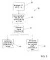
- FIG. 3is a flow chart of a process according to the invention for analog stabilization of the sensor scale factor.
- the inventionis directed to an analog signal processing system for fiber optic sensors.
- the digital signal processing system described hereinmay be used to stabilize the sensor scale factor.
- the fiber optic sensor coilmay measure physical quantities, such as a rotation rate or a magnetic field.
- FIG. 1illustrates a conventional interferometric fiber optic sensor.
- Light emitted from a suitable light source 30may pass through a first 3 dB coupler 1 where half of the light may be dissipated, and half may be sent into the interferometer through the polarizer 2 .
- a second 3 dB coupler 3may then split the light into two approximately equal intensity, counter-propagating beams which traverse the coil.
- the two light beams exiting the coilmay then recombine at the second coupler 3 where they may interfere.
- the recombined light beammay then pass through the polarizer 2 a second time in the opposite direction, and half of the light may be directed to the photodetector 24 by the first coupler 1 .
- An optical splitting ratio of 3 dBmay typically be selected for the couplers to maximize the optical power incident on the detector. In some embodiments, other splitting ratios may also be selected for the first and second couplers.
- a magnetic field sensorwhich may be used to sense an electric current, operates according to the same principle with the addition of two ⁇ /4 waveplates 51 , 52 that may be placed near the sensor coil ends.
- a piezo-electric transducer (PZT) 20may be used to modulate the phase difference between the two counter-propagating light beams.
- Other methods of modulating the phase differencefor example, electro-optic material such as lithium niobate or non-linear polymers may also be employed.
- This phase modulationmay serve two purposes. The modulation may dynamically bias the interferometer to a more sensitive operating point and may also allow the determination of rotation sense. Further, if the phase modulation is varying, it may move the detected signal from direct current (DC) to alternating current (AC) in order to improve the accuracy of the electrical signal processing.
- DCdirect current
- ACalternating current
- the interferometer output signalmay be an infinite series of sine and cosine waveforms whose amplitudes are proportional to Bessel functions evaluated at the phase modulation depth.
- the ratios of the fundamental and several of the lowest order harmonic signal amplitudesmay be used to detect rotation rate and/or magnetic field, while at the same time maintaining a stable, linear output scale factor.
- the light source and modulatormay be controlled via drivers 5 , 8 by analog and/or digital electronic hardware 6 which may receive input signals from detector 24 via amplifier 7 .
- the fiber optic sensormay also have a reduced minimum configuration (RMC) as disclosed, for example, in the pending U.S. patent application No. 09/459,438 and the concurrently filed U.S. application entitled “Reduced minimum configuration fiber optic current sensor” to Sidney Bennett (Atty. Docket No. KVC-019.03 and now U.S. Pat. No. 6,351,310 B1), both of which are commonly assigned to the assignee of the present application and are incorporated herein by reference.
- RMCreduced minimum configuration
- the scale factoris the coefficient that relates the measured signal to the rotation rate.
- the scale factormay be dependent on both the optical intensity (optical power from the light source) at the detector, and the modulation depth ⁇ (also known as the modulation index).
- the scale factormay be proportional to J 1 ( ⁇ ), because the signal component at f m is proportional to J 1 ( ⁇ ).
- the scale factormay be inversely proportional to J 2 ( ⁇ ). Then the scale factor (SF) may be written as
- kis a constant, dependent on the fiber optic sensor configuration and not affected by environmental conditions; and ⁇ is the phase modulation depth.
- a large variation in the scale factor with the modulation depthmay be introduced by a large value of the derivative d ⁇ J 2 ( ⁇ ) ⁇ /d ⁇ .
- controlling the optical power level of the light source 30 by using the level of the second harmonic signalmay increase the percentage change in scale factor by more than an order of magnitude at high rotation rates, making the sensor scale factor extremely unstable. For this reason, while the second harmonic is commonly used to control the optical power level, it is somewhat unsatisfactory.
- a frequency sourcesuch as the oscillator/driver 5 or another oscillator (not shown), which may operate at a frequency f p , may be used to modulate the amplitude of the modulator drive voltage, producing an amplitude modulation of the phase modulation depth ⁇ .
- sensor signals at the fundamental frequency and the harmonic frequencies of the PZT modulation frequency f mare also amplitude-modulated at the frequency f p . It thus follows that the amplitude levels of these signals are proportional to the Bessel functions J 0 ( ⁇ ), J 1 ( ⁇ ), J 2 ( ⁇ ) . . . J n ( ⁇ ).
- the level of the DC componentis proportional to J 0 ( ⁇ ), so that the amplitude of the superimposed modulation at f p is proportional to the slope of J 0 ( ⁇ ), i.e., J 0 '( ⁇ ).
- J 0 '( ⁇ )⁇ J 1 ( ⁇ ).
- the modulation amplitude at f pmay be used to control the light source drive and thereby the optical power of the light emitted by the light source 30 to stabilize the sensor scale factor.
- the power level of the light source 30is controlled by J' 0 ( ⁇ ), instead of J 2 ( ⁇ ), so that
- the scale factormay become independent of variations in the modulation depth when the signal amplitude at the amplitude modulation frequency f p is used to control the light source drive and thereby the optical power of the light emitted by the light source.
- the system of the present inventionmay operate by comparing the signal 14 obtained from the detector at f p with a signal 12 derived directly from the modulator, thereby removing fluctuations in the oscillating amplitude at frequency f p .
- the resultant signalmay be used to stabilize the drive of the light source, as described above.
- the PZTmay have a relatively slow response to amplitude modulation because of a relatively high Q-value of the disk.
- the modulated signalmay have a frequency limit of, for example, 1 kHz.
- a modulation at such a low-frequency f pmay nevertheless amplitude modulate the sensor output signal.
- the amplitude modulation of the PZT drive at a low-frequency f pmay not only produce a signal at the detector at the frequency f p with a level proportional to J 0 '( ⁇ ), but also a second harmonic at the frequency 2f p .
- the modulation index ⁇may be kept at its optimal level by a feedback loop which keeps the amplitude of the second harmonic (the signal component measured at the detector at twice the amplitude modulation frequency, 2f p ) equal to zero.
- An embodiment of the inventionmay have the additional advantage that the second harmonic signal with its cosine dependence on the Sagnac phase angle ⁇ need no longer be used. This advantageously may produce a sin ⁇ / ⁇ response of the fiber optic sensor, rather than the tan ⁇ / ⁇ response obtained with conventional systems, thereby greatly improving the dynamic range.
- FIG. 2shows the amplitude of the 0 th order Bessel functions J 0 ( ⁇ ), the derivative ⁇ J 0 '( ⁇ ) of the 0 th order Bessel functions J 0 ( ⁇ ), and the 1 st order Bessel function J 1 ( ⁇ ).
- the fundamental and the first harmonic frequencyare required to characterize the fiber optic sensor scale factor.
- the PZT modulator 20 of FIG. 1may be modulated by a modulation frequency f p in addition to the PZT drive frequency f m , step 34 .
- f pis selected to be different from f m .
- Photodetector 24 of FIG. 1may detect at step 36 , in the manner as previously described, the amplitude of the superimposed modulation f p and a second harmonic at the frequency 2*f p , which may be transmitted to signal processor 6 of FIG. 1 at step 38 .
- signal processor 6may control the power source 30 of FIG. 1 via the LD driver 8 of FIG.
- the signal processor 6may control the power source 30 via LD driver 8 , such that the signal component at the frequency 2*f p may be maintained at a zero amplitude. Both embodiments are seen to maintain the scale factor of the fiber optic sensor with great accuracy.
Landscapes
- Engineering & Computer Science (AREA)
- Physics & Mathematics (AREA)
- Power Engineering (AREA)
- General Physics & Mathematics (AREA)
- Optics & Photonics (AREA)
- Electromagnetism (AREA)
- Radar, Positioning & Navigation (AREA)
- Remote Sensing (AREA)
- Gyroscopes (AREA)
- Lasers (AREA)
Abstract
Description
Claims (13)
Priority Applications (1)
| Application Number | Priority Date | Filing Date | Title |
|---|---|---|---|
| US09/906,019US6594020B2 (en) | 2000-07-13 | 2001-07-13 | Method for controlling fiber optic sensor scale factor using amplitude modulation |
Applications Claiming Priority (2)
| Application Number | Priority Date | Filing Date | Title |
|---|---|---|---|
| US21808600P | 2000-07-13 | 2000-07-13 | |
| US09/906,019US6594020B2 (en) | 2000-07-13 | 2001-07-13 | Method for controlling fiber optic sensor scale factor using amplitude modulation |
Publications (2)
| Publication Number | Publication Date |
|---|---|
| US20020025098A1 US20020025098A1 (en) | 2002-02-28 |
| US6594020B2true US6594020B2 (en) | 2003-07-15 |
Family
ID=22813684
Family Applications (1)
| Application Number | Title | Priority Date | Filing Date |
|---|---|---|---|
| US09/906,019Expired - Fee RelatedUS6594020B2 (en) | 2000-07-13 | 2001-07-13 | Method for controlling fiber optic sensor scale factor using amplitude modulation |
Country Status (3)
| Country | Link |
|---|---|
| US (1) | US6594020B2 (en) |
| AU (1) | AU2001280542A1 (en) |
| WO (1) | WO2002006769A2 (en) |
Cited By (5)
| Publication number | Priority date | Publication date | Assignee | Title |
|---|---|---|---|---|
| US20020031292A1 (en)* | 2000-08-02 | 2002-03-14 | Richard Dyott | Reduction of linear birefringence in circular-cored single-mode fiber |
| US20040179852A1 (en)* | 1996-07-19 | 2004-09-16 | Microwave Photonics, Inc. | Telecommunications system |
| US20070003285A1 (en)* | 2005-06-30 | 2007-01-04 | Meyer A D | Optical signal source wavelength stabilization system and method |
| US20070121117A1 (en)* | 2005-11-29 | 2007-05-31 | Honeywell International, Inc. | Method and system for calibrating a fiber optic gyroscope |
| RU2516369C2 (en)* | 2012-09-12 | 2014-05-20 | Валерий Николаевич Логозинский | Method to produce scale ratio of fibre-optic gyroscope |
Families Citing this family (4)
| Publication number | Priority date | Publication date | Assignee | Title |
|---|---|---|---|---|
| US6891622B2 (en) | 1999-02-11 | 2005-05-10 | Kvh Industries, Inc. | Current sensor |
| JP5904694B2 (en) | 2009-12-10 | 2016-04-20 | 株式会社東芝 | Sagnac interferometric photocurrent sensor |
| CN108614143A (en)* | 2018-04-27 | 2018-10-02 | 许继集团有限公司 | A kind of all-fiber current transformator acquisition system and all-fiber current transformator |
| CN109212458B (en)* | 2018-10-22 | 2020-11-24 | 国网冀北电力有限公司唐山供电公司 | A Measurement Method of Sagnac Interferometric High Current Fiber Optic Current Transformer Based on Non-reciprocal Phase Shift Equipment |
Citations (89)
| Publication number | Priority date | Publication date | Assignee | Title |
|---|---|---|---|---|
| FR2535463A1 (en) | 1982-10-28 | 1984-05-04 | Commissariat Energie Atomique | Device for measuring electric current based on the Faraday effect |
| DE3305104A1 (en) | 1983-02-15 | 1984-08-16 | Licentia Patent-Verwaltungs-Gmbh, 6000 Frankfurt | Fibre-optic polariser |
| US4571650A (en) | 1982-09-07 | 1986-02-18 | Hitachi, Ltd. | Magneto-optic information storage system utilizing a self-coupled laser |
| US4603931A (en) | 1984-12-14 | 1986-08-05 | Ruffman Samuel H | Anti-theft device for appliances with electrical AC power cords |
| US4615582A (en) | 1981-11-09 | 1986-10-07 | The Board Of Trustees Of The Leland Stanford Junior University | Magneto-optic rotator for providing additive Faraday rotations in a loop of optical fiber |
| US4630229A (en) | 1982-02-23 | 1986-12-16 | Intercontrole Societe Anonyme | Circuit for the fast calculation of the discrete Fourier transform of a signal |
| US4630890A (en) | 1983-06-22 | 1986-12-23 | At&T Bell Laboratories | Exposed core optical fibers, and method of making same |
| US4637722A (en) | 1983-04-25 | 1987-01-20 | The Board Of Trustees Of The Leland Stanford Junior University | Fiber optical rotation sensor with extended dynamic range |
| US4668264A (en) | 1982-08-02 | 1987-05-26 | Andrew Corporation | Method for making self-aligning optical fiber with accessible guiding region |
| US4669814A (en) | 1982-08-02 | 1987-06-02 | Andrew Corporation | Single mode, single polarization optical fiber with accessible guiding region and method of forming directional coupler using same |
| US4697876A (en) | 1983-02-25 | 1987-10-06 | Andrew Corporation | Fiber-optic rotation sensor |
| DE3615305A1 (en) | 1985-09-28 | 1987-11-12 | Licentia Gmbh | Process for producing a fibre-optical polariser |
| US4712866A (en) | 1986-07-24 | 1987-12-15 | Andrew Corporation | Indium-clad fiber-optic polarizer |
| US4733938A (en) | 1981-11-09 | 1988-03-29 | The Board Of Trustees Of The Leland Stanford Junior University | Magneto-optic rotator |
| US4740085A (en) | 1986-02-18 | 1988-04-26 | Northrop Corporation | Scale factor stability control |
| US4755021A (en) | 1982-08-02 | 1988-07-05 | Andrew Corporation | Self-aligning optical fiber directional coupler and fiber-ring optical rotation sensor using same |
| US4756589A (en) | 1985-02-12 | 1988-07-12 | Stc Plc | Optical coupler utilizing low or zero birefringence optical fibers and a method of making same |
| US4765739A (en) | 1985-11-06 | 1988-08-23 | Kabushiki Kaisha Toshiba | Fiber optical rotation sensor utilizing the Sagnac phase difference |
| US4776700A (en) | 1987-09-30 | 1988-10-11 | The United States Of America As Represented By The Secretary Of The Navy | Switched state fiber optic gyroscope |
| US4796993A (en) | 1987-04-13 | 1989-01-10 | Hitachi, Ltd. | Phase modulation type fiber optic gyroscope |
| US4815817A (en) | 1988-04-06 | 1989-03-28 | Raynet Corporation | D-shaped fiber |
| DE3742201A1 (en) | 1987-12-12 | 1989-06-22 | Teldix Gmbh | Fibre gyroscope |
| US4842409A (en) | 1985-05-30 | 1989-06-27 | Thomson-Csf | Monomode optical fiber ring interferometric device with semiconductor diode as light energy emission reception/amplification means |
| US4848910A (en) | 1987-06-11 | 1989-07-18 | Alsthom | Sagnac type optical fiber interferometer system |
| US4883358A (en) | 1987-09-02 | 1989-11-28 | Japan Aviation Electronics Industry Limited | Fiber optic gyro stabilized by harmonic components of detected signal |
| US4887900A (en) | 1987-02-20 | 1989-12-19 | Litton Systems, Inc. | Polarization maintaining fiber interferometer and method for source stabilization |
| US4943132A (en) | 1988-10-23 | 1990-07-24 | Huang Hung Chia | Passive fiber-optic polarization control |
| US5033854A (en) | 1989-12-06 | 1991-07-23 | Litton Systems, Inc. | Multiplexed fiberoptic gyro control |
| US5048962A (en) | 1989-05-15 | 1991-09-17 | Mitsubishi Precision Co., Ltd. | Optical gyro, signal processing apparatus for the same and method of driving phase modulator used in the same |
| US5063290A (en) | 1990-09-14 | 1991-11-05 | The United States Of America As Represented By The Secretary Of The Navy | All-optical fiber faraday rotation current sensor with heterodyne detection technique |
| US5074665A (en) | 1989-12-21 | 1991-12-24 | Andrew Corporation | Fiber optic gyroscope using dual-section counter-wound coil |
| US5080489A (en) | 1989-03-29 | 1992-01-14 | Kubota, Ltd. | Fiber optic gyroscope for detecting angular velocity of rotation using equivalent time sampling |
| US5106193A (en) | 1990-08-09 | 1992-04-21 | The Board Of Trustees Of The Leland Stanford Junior University | Optical waveguide amplifier source gyroscope |
| US5133600A (en) | 1989-06-02 | 1992-07-28 | Litef Gmbh | Method and apparatus for demodulating the rotation rate signal of a fiber optic gyroscope |
| US5135555A (en) | 1989-12-21 | 1992-08-04 | At&T Bell Laboratories | Apparatus for fabrication of optical couplers |
| US5136235A (en) | 1989-12-01 | 1992-08-04 | Asea Brown Boveri Ltd. | Rugged fiber-optical current sensor based on the faraday effect |
| EP0551874A2 (en) | 1992-01-16 | 1993-07-21 | Japan Aviation Electronics Industry, Limited | Fiber optic gyro |
| US5289258A (en) | 1992-01-15 | 1994-02-22 | Honeywell Inc. | Fiber optic gyroscope modulation error reduction |
| US5289257A (en) | 1991-05-17 | 1994-02-22 | Mitsubishi Precision Co., Ltd. | Signal processing apparatus for optical gyro |
| EP0586242A1 (en) | 1992-09-02 | 1994-03-09 | Sumitomo Electric Industries, Ltd. | Fiber-optic gyroscope |
| US5331404A (en) | 1992-11-30 | 1994-07-19 | The United States Of America As Represented By The Secretary Of The Navy | Low noise fiber gyroscope system which includes excess noise subtraction |
| US5351123A (en) | 1992-01-13 | 1994-09-27 | Litef Gmbh | Method and apparatus for stabilizing control loop scale factor and gain in a fiber optic Sagnac interferometer |
| US5359413A (en) | 1992-01-13 | 1994-10-25 | Kearfott Guidance And Navigation Corporation | System for substantially eleminating lock-in in a ring laser gyroscope |
| US5365338A (en) | 1991-05-28 | 1994-11-15 | The United States Of America As Represented By The Secretary Of The Navy | Wavelength sensor for fiber optic gyroscope |
| US5406370A (en) | 1993-02-26 | 1995-04-11 | The Board Of Trustees Of The Leland Stanford University | Winding technique for decreasing the pump power requirement of a brillouin fiber optic gyroscope |
| US5412471A (en) | 1991-03-12 | 1995-05-02 | Mitsubishi Precision Co., Ltd. | Optical gyro with expanded detectable range of input rotation angular velocity and optical waveguide-type phase modulator used in the same |
| JPH07209398A (en) | 1994-01-24 | 1995-08-11 | Nissin Electric Co Ltd | Faraday effect type optical fiber sensor and current transformer |
| US5459575A (en) | 1993-02-27 | 1995-10-17 | British Aerospace Plc | Laser fiber optic gyroscope having phase modulation |
| US5469267A (en) | 1994-04-08 | 1995-11-21 | The University Of Rochester | Halftone correction system |
| US5469257A (en) | 1993-11-24 | 1995-11-21 | Honeywell Inc. | Fiber optic gyroscope output noise reducer |
| US5471301A (en) | 1993-08-23 | 1995-11-28 | Hitachi Cable, Ltd. | Optical fiber gyro |
| EP0686867A1 (en) | 1994-06-09 | 1995-12-13 | CeramOptec GmbH | All fiber in-line optical isolator |
| US5493396A (en) | 1993-11-30 | 1996-02-20 | Honeywell Inc. | High resolution ring laser gyroscope readout |
| US5500909A (en) | 1993-02-17 | 1996-03-19 | Abb Research Ltd. | Sensor head for a fiber-optic current measuring device |
| US5504684A (en) | 1993-12-10 | 1996-04-02 | Trimble Navigation Limited | Single-chip GPS receiver digital signal processing and microcomputer |
| EP0722081A2 (en) | 1990-03-19 | 1996-07-17 | Eli Lilly And Company | Fiberoptic interferometric sensor |
| US5552887A (en) | 1995-04-07 | 1996-09-03 | Andrew Corporation | Fiber optic rotation sensor or gyroscope with improved sensing coil |
| US5559908A (en) | 1994-05-31 | 1996-09-24 | Honeywell Inc. | Method for damping optical fiber on a bias optical phase modulator |
| US5602642A (en) | 1995-06-07 | 1997-02-11 | Honeywell Inc. | Magnetically insensitive fiber optic rotation sensor |
| US5644397A (en) | 1994-10-07 | 1997-07-01 | The Texas A&M University System | Fiber optic interferometric circuit and magnetic field sensor |
| US5654906A (en) | 1995-07-06 | 1997-08-05 | Youngquist; John S. | Rate gyro error correction and use as heading source |
| US5655035A (en) | 1995-11-16 | 1997-08-05 | Alliedsignal Inc. | Differential fiber optic angular rate sensor for minimizing common mode noise in the sensor output |
| US5682241A (en) | 1996-03-11 | 1997-10-28 | Litton Systems, Inc. | Method and apparatus for overcoming cross-coupling in a fiber optic gyroscope employing overmodulation |
| US5701177A (en) | 1993-11-16 | 1997-12-23 | Hitachi Cable, Ltd. | Method for detecting fault of optical fiber gyro and apparatus for diagnosing fault of the same |
| US5701376A (en) | 1995-07-26 | 1997-12-23 | Fujitsu Limited | Polarized-wave-dispersion- preventive optical fiber and its manufacturing method |
| US5767509A (en) | 1996-12-24 | 1998-06-16 | Litton Systems, Inc. | Fiber optic sensor coil including buffer regions |
| US5781675A (en) | 1997-03-14 | 1998-07-14 | National Science Council | Method for preparing fiber-optic polarizer |
| EP0856737A1 (en) | 1997-01-29 | 1998-08-05 | Abb Research Ltd. | Magneto optical current sensor |
| EP0872756A1 (en) | 1997-04-14 | 1998-10-21 | BRITISH TELECOMMUNICATIONS public limited company | Optical modulator |
| WO1998058268A1 (en) | 1997-06-19 | 1998-12-23 | The Texas A & M University System | Fiber optic interferometric sensor |
| US5854864A (en) | 1996-07-16 | 1998-12-29 | The Regents Of The University Of California | In-line polymeric construct for modulators, filters, switches and other electro-optic devices |
| US5898496A (en) | 1997-02-14 | 1999-04-27 | Allied Signal Inc | Optical signal noise reduction for fiber optic gyroscopses |
| US5946097A (en) | 1997-12-31 | 1999-08-31 | Honeywell Inc. | Vibration rectification error reducer for fiber optic gyroscope |
| US5949545A (en)* | 1996-05-23 | 1999-09-07 | Alliedsignal Inc. | Fiber optic gyroscope with variable output period |
| US5953122A (en)* | 1997-07-16 | 1999-09-14 | Litef Gmbh | Method and apparatus for increasing the stability of a fiber optic gyroscope by controlling the phase and amplitude of the source modulating current |
| US5987195A (en) | 1996-08-01 | 1999-11-16 | The Texas A&M University System | Fiber optics apparatus and method for accurate current sensing |
| US6025915A (en) | 1998-06-25 | 2000-02-15 | Litton Systems, Inc. | Scale factor stabilization of a broadband fiber source used in fiber optic gyroscopes in radiation environments |
| US6028668A (en)* | 1998-02-04 | 2000-02-22 | Rockwell Collins, Inc. | Fiber optic gyroscope having improved readout and modulation index control |
| WO2000031551A1 (en) | 1998-11-23 | 2000-06-02 | The Texas A & M University System | Displacement current based voltage sensor |
| US6075915A (en) | 1997-03-29 | 2000-06-13 | Koops; Hans W. P. | In-fiber photonic crystals and systems |
| WO2000036425A2 (en) | 1998-11-12 | 2000-06-22 | Honeywell Inc. | Fiber optic current sensor having rotation immunity |
| US6148131A (en) | 1995-08-16 | 2000-11-14 | Plasma Optical Fibre B.V. | Method of making a twisted optical fiber with low polarization mode dispersion |
| US6163632A (en) | 1997-09-23 | 2000-12-19 | Bookham Technology Plc | Integrated optical circuit |
| US6185033B1 (en) | 1998-03-30 | 2001-02-06 | France Telecom | Hybrid integrated electro-optical modulator of the pockels effect type |
| US6233371B1 (en) | 1997-05-22 | 2001-05-15 | Donam Systems Inc. | Optical fiber polarization controller |
| US6351310B1 (en) | 1996-04-19 | 2002-02-26 | Kvh Industries, Inc. | Reduced minimum configuration interferometric fiber optic gyroscope with simplified signal processing electronics |
| US6370289B1 (en) | 2000-01-12 | 2002-04-09 | Kvh Industries, Inc. | Apparatus and method for electronic RIN reduction in fiber-optic sensors |
| US6389185B1 (en) | 2001-01-08 | 2002-05-14 | Lockheed Martin Corporation | Light polarization transformer |
| US6396965B1 (en) | 2000-11-22 | 2002-05-28 | Tektronix, Inc. | Twisting fiber depolarizer |
- 2001
- 2001-07-13USUS09/906,019patent/US6594020B2/ennot_activeExpired - Fee Related
- 2001-07-13AUAU2001280542Apatent/AU2001280542A1/ennot_activeAbandoned
- 2001-07-13WOPCT/US2001/022127patent/WO2002006769A2/enactiveApplication Filing
Patent Citations (95)
| Publication number | Priority date | Publication date | Assignee | Title |
|---|---|---|---|---|
| US4615582A (en) | 1981-11-09 | 1986-10-07 | The Board Of Trustees Of The Leland Stanford Junior University | Magneto-optic rotator for providing additive Faraday rotations in a loop of optical fiber |
| US4733938A (en) | 1981-11-09 | 1988-03-29 | The Board Of Trustees Of The Leland Stanford Junior University | Magneto-optic rotator |
| US4630229A (en) | 1982-02-23 | 1986-12-16 | Intercontrole Societe Anonyme | Circuit for the fast calculation of the discrete Fourier transform of a signal |
| US4755021A (en) | 1982-08-02 | 1988-07-05 | Andrew Corporation | Self-aligning optical fiber directional coupler and fiber-ring optical rotation sensor using same |
| US4668264A (en) | 1982-08-02 | 1987-05-26 | Andrew Corporation | Method for making self-aligning optical fiber with accessible guiding region |
| US4669814A (en) | 1982-08-02 | 1987-06-02 | Andrew Corporation | Single mode, single polarization optical fiber with accessible guiding region and method of forming directional coupler using same |
| US4571650A (en) | 1982-09-07 | 1986-02-18 | Hitachi, Ltd. | Magneto-optic information storage system utilizing a self-coupled laser |
| FR2535463A1 (en) | 1982-10-28 | 1984-05-04 | Commissariat Energie Atomique | Device for measuring electric current based on the Faraday effect |
| DE3305104A1 (en) | 1983-02-15 | 1984-08-16 | Licentia Patent-Verwaltungs-Gmbh, 6000 Frankfurt | Fibre-optic polariser |
| US4697876A (en) | 1983-02-25 | 1987-10-06 | Andrew Corporation | Fiber-optic rotation sensor |
| US4637722A (en) | 1983-04-25 | 1987-01-20 | The Board Of Trustees Of The Leland Stanford Junior University | Fiber optical rotation sensor with extended dynamic range |
| US4630890A (en) | 1983-06-22 | 1986-12-23 | At&T Bell Laboratories | Exposed core optical fibers, and method of making same |
| US4603931A (en) | 1984-12-14 | 1986-08-05 | Ruffman Samuel H | Anti-theft device for appliances with electrical AC power cords |
| US4756589A (en) | 1985-02-12 | 1988-07-12 | Stc Plc | Optical coupler utilizing low or zero birefringence optical fibers and a method of making same |
| US4842409A (en) | 1985-05-30 | 1989-06-27 | Thomson-Csf | Monomode optical fiber ring interferometric device with semiconductor diode as light energy emission reception/amplification means |
| DE3615305A1 (en) | 1985-09-28 | 1987-11-12 | Licentia Gmbh | Process for producing a fibre-optical polariser |
| US4765739A (en) | 1985-11-06 | 1988-08-23 | Kabushiki Kaisha Toshiba | Fiber optical rotation sensor utilizing the Sagnac phase difference |
| US4740085A (en) | 1986-02-18 | 1988-04-26 | Northrop Corporation | Scale factor stability control |
| US4712866A (en) | 1986-07-24 | 1987-12-15 | Andrew Corporation | Indium-clad fiber-optic polarizer |
| US4887900A (en) | 1987-02-20 | 1989-12-19 | Litton Systems, Inc. | Polarization maintaining fiber interferometer and method for source stabilization |
| US4796993A (en) | 1987-04-13 | 1989-01-10 | Hitachi, Ltd. | Phase modulation type fiber optic gyroscope |
| US4848910A (en) | 1987-06-11 | 1989-07-18 | Alsthom | Sagnac type optical fiber interferometer system |
| US4883358A (en) | 1987-09-02 | 1989-11-28 | Japan Aviation Electronics Industry Limited | Fiber optic gyro stabilized by harmonic components of detected signal |
| US4776700A (en) | 1987-09-30 | 1988-10-11 | The United States Of America As Represented By The Secretary Of The Navy | Switched state fiber optic gyroscope |
| DE3742201A1 (en) | 1987-12-12 | 1989-06-22 | Teldix Gmbh | Fibre gyroscope |
| US4815817A (en) | 1988-04-06 | 1989-03-28 | Raynet Corporation | D-shaped fiber |
| US4943132A (en) | 1988-10-23 | 1990-07-24 | Huang Hung Chia | Passive fiber-optic polarization control |
| US5096312A (en) | 1988-10-23 | 1992-03-17 | Huang Hung Chia | Passive fiber-optic polarization control element |
| US5080489A (en) | 1989-03-29 | 1992-01-14 | Kubota, Ltd. | Fiber optic gyroscope for detecting angular velocity of rotation using equivalent time sampling |
| US5048962A (en) | 1989-05-15 | 1991-09-17 | Mitsubishi Precision Co., Ltd. | Optical gyro, signal processing apparatus for the same and method of driving phase modulator used in the same |
| US5133600A (en) | 1989-06-02 | 1992-07-28 | Litef Gmbh | Method and apparatus for demodulating the rotation rate signal of a fiber optic gyroscope |
| US5136235A (en) | 1989-12-01 | 1992-08-04 | Asea Brown Boveri Ltd. | Rugged fiber-optical current sensor based on the faraday effect |
| US5033854A (en) | 1989-12-06 | 1991-07-23 | Litton Systems, Inc. | Multiplexed fiberoptic gyro control |
| US5074665A (en) | 1989-12-21 | 1991-12-24 | Andrew Corporation | Fiber optic gyroscope using dual-section counter-wound coil |
| US5135555A (en) | 1989-12-21 | 1992-08-04 | At&T Bell Laboratories | Apparatus for fabrication of optical couplers |
| EP0722081A2 (en) | 1990-03-19 | 1996-07-17 | Eli Lilly And Company | Fiberoptic interferometric sensor |
| US5106193A (en) | 1990-08-09 | 1992-04-21 | The Board Of Trustees Of The Leland Stanford Junior University | Optical waveguide amplifier source gyroscope |
| US5063290A (en) | 1990-09-14 | 1991-11-05 | The United States Of America As Represented By The Secretary Of The Navy | All-optical fiber faraday rotation current sensor with heterodyne detection technique |
| US5412471A (en) | 1991-03-12 | 1995-05-02 | Mitsubishi Precision Co., Ltd. | Optical gyro with expanded detectable range of input rotation angular velocity and optical waveguide-type phase modulator used in the same |
| US5289257A (en) | 1991-05-17 | 1994-02-22 | Mitsubishi Precision Co., Ltd. | Signal processing apparatus for optical gyro |
| US5365338A (en) | 1991-05-28 | 1994-11-15 | The United States Of America As Represented By The Secretary Of The Navy | Wavelength sensor for fiber optic gyroscope |
| US5351123A (en) | 1992-01-13 | 1994-09-27 | Litef Gmbh | Method and apparatus for stabilizing control loop scale factor and gain in a fiber optic Sagnac interferometer |
| US5359413A (en) | 1992-01-13 | 1994-10-25 | Kearfott Guidance And Navigation Corporation | System for substantially eleminating lock-in in a ring laser gyroscope |
| US5289258A (en) | 1992-01-15 | 1994-02-22 | Honeywell Inc. | Fiber optic gyroscope modulation error reduction |
| EP0551874A2 (en) | 1992-01-16 | 1993-07-21 | Japan Aviation Electronics Industry, Limited | Fiber optic gyro |
| EP0586242A1 (en) | 1992-09-02 | 1994-03-09 | Sumitomo Electric Industries, Ltd. | Fiber-optic gyroscope |
| US5331404A (en) | 1992-11-30 | 1994-07-19 | The United States Of America As Represented By The Secretary Of The Navy | Low noise fiber gyroscope system which includes excess noise subtraction |
| US5500909A (en) | 1993-02-17 | 1996-03-19 | Abb Research Ltd. | Sensor head for a fiber-optic current measuring device |
| US5406370A (en) | 1993-02-26 | 1995-04-11 | The Board Of Trustees Of The Leland Stanford University | Winding technique for decreasing the pump power requirement of a brillouin fiber optic gyroscope |
| US5459575A (en) | 1993-02-27 | 1995-10-17 | British Aerospace Plc | Laser fiber optic gyroscope having phase modulation |
| US5471301A (en) | 1993-08-23 | 1995-11-28 | Hitachi Cable, Ltd. | Optical fiber gyro |
| US5701177A (en) | 1993-11-16 | 1997-12-23 | Hitachi Cable, Ltd. | Method for detecting fault of optical fiber gyro and apparatus for diagnosing fault of the same |
| US5469257A (en) | 1993-11-24 | 1995-11-21 | Honeywell Inc. | Fiber optic gyroscope output noise reducer |
| US5493396A (en) | 1993-11-30 | 1996-02-20 | Honeywell Inc. | High resolution ring laser gyroscope readout |
| US5504684A (en) | 1993-12-10 | 1996-04-02 | Trimble Navigation Limited | Single-chip GPS receiver digital signal processing and microcomputer |
| JPH07209398A (en) | 1994-01-24 | 1995-08-11 | Nissin Electric Co Ltd | Faraday effect type optical fiber sensor and current transformer |
| US5469267A (en) | 1994-04-08 | 1995-11-21 | The University Of Rochester | Halftone correction system |
| US5559908A (en) | 1994-05-31 | 1996-09-24 | Honeywell Inc. | Method for damping optical fiber on a bias optical phase modulator |
| EP0686867A1 (en) | 1994-06-09 | 1995-12-13 | CeramOptec GmbH | All fiber in-line optical isolator |
| US5644397A (en) | 1994-10-07 | 1997-07-01 | The Texas A&M University System | Fiber optic interferometric circuit and magnetic field sensor |
| US5552887A (en) | 1995-04-07 | 1996-09-03 | Andrew Corporation | Fiber optic rotation sensor or gyroscope with improved sensing coil |
| US5602642A (en) | 1995-06-07 | 1997-02-11 | Honeywell Inc. | Magnetically insensitive fiber optic rotation sensor |
| US5654906A (en) | 1995-07-06 | 1997-08-05 | Youngquist; John S. | Rate gyro error correction and use as heading source |
| US5701376A (en) | 1995-07-26 | 1997-12-23 | Fujitsu Limited | Polarized-wave-dispersion- preventive optical fiber and its manufacturing method |
| US6148131A (en) | 1995-08-16 | 2000-11-14 | Plasma Optical Fibre B.V. | Method of making a twisted optical fiber with low polarization mode dispersion |
| US5655035A (en) | 1995-11-16 | 1997-08-05 | Alliedsignal Inc. | Differential fiber optic angular rate sensor for minimizing common mode noise in the sensor output |
| US5682241A (en) | 1996-03-11 | 1997-10-28 | Litton Systems, Inc. | Method and apparatus for overcoming cross-coupling in a fiber optic gyroscope employing overmodulation |
| EP0871009A1 (en) | 1996-03-11 | 1998-10-14 | Litton Systems | Rotation rate measurement and fiber optic gyroscopes |
| US6351310B1 (en) | 1996-04-19 | 2002-02-26 | Kvh Industries, Inc. | Reduced minimum configuration interferometric fiber optic gyroscope with simplified signal processing electronics |
| US5949545A (en)* | 1996-05-23 | 1999-09-07 | Alliedsignal Inc. | Fiber optic gyroscope with variable output period |
| US6047095A (en) | 1996-07-16 | 2000-04-04 | The Regents Of The University Of California | In-line polymeric construct for modulators, filters, switches and other electro-optic devices |
| US5854864A (en) | 1996-07-16 | 1998-12-29 | The Regents Of The University Of California | In-line polymeric construct for modulators, filters, switches and other electro-optic devices |
| US5987195A (en) | 1996-08-01 | 1999-11-16 | The Texas A&M University System | Fiber optics apparatus and method for accurate current sensing |
| US5767509A (en) | 1996-12-24 | 1998-06-16 | Litton Systems, Inc. | Fiber optic sensor coil including buffer regions |
| US5953121A (en) | 1997-01-29 | 1999-09-14 | Abb Research Ltd. | Magneto-optic current sensor having a mechanically stress-free λ/4 element |
| EP0856737A1 (en) | 1997-01-29 | 1998-08-05 | Abb Research Ltd. | Magneto optical current sensor |
| US5898496A (en) | 1997-02-14 | 1999-04-27 | Allied Signal Inc | Optical signal noise reduction for fiber optic gyroscopses |
| US5781675A (en) | 1997-03-14 | 1998-07-14 | National Science Council | Method for preparing fiber-optic polarizer |
| US6075915A (en) | 1997-03-29 | 2000-06-13 | Koops; Hans W. P. | In-fiber photonic crystals and systems |
| EP0872756A1 (en) | 1997-04-14 | 1998-10-21 | BRITISH TELECOMMUNICATIONS public limited company | Optical modulator |
| US6233371B1 (en) | 1997-05-22 | 2001-05-15 | Donam Systems Inc. | Optical fiber polarization controller |
| WO1998058268A1 (en) | 1997-06-19 | 1998-12-23 | The Texas A & M University System | Fiber optic interferometric sensor |
| US6023331A (en) | 1997-06-19 | 2000-02-08 | The Texas A&M University System | Fiber optic interferometric sensor and method by adding controlled amounts of circular birefringence in the sensing fiber |
| US5953122A (en)* | 1997-07-16 | 1999-09-14 | Litef Gmbh | Method and apparatus for increasing the stability of a fiber optic gyroscope by controlling the phase and amplitude of the source modulating current |
| US6163632A (en) | 1997-09-23 | 2000-12-19 | Bookham Technology Plc | Integrated optical circuit |
| US5946097A (en) | 1997-12-31 | 1999-08-31 | Honeywell Inc. | Vibration rectification error reducer for fiber optic gyroscope |
| US6028668A (en)* | 1998-02-04 | 2000-02-22 | Rockwell Collins, Inc. | Fiber optic gyroscope having improved readout and modulation index control |
| US6185033B1 (en) | 1998-03-30 | 2001-02-06 | France Telecom | Hybrid integrated electro-optical modulator of the pockels effect type |
| US6025915A (en) | 1998-06-25 | 2000-02-15 | Litton Systems, Inc. | Scale factor stabilization of a broadband fiber source used in fiber optic gyroscopes in radiation environments |
| WO2000036425A2 (en) | 1998-11-12 | 2000-06-22 | Honeywell Inc. | Fiber optic current sensor having rotation immunity |
| US6301400B1 (en) | 1998-11-12 | 2001-10-09 | Nxtphase Technologies Srl | Fiber optic current sensor having rotation immunity |
| WO2000031551A1 (en) | 1998-11-23 | 2000-06-02 | The Texas A & M University System | Displacement current based voltage sensor |
| US6370289B1 (en) | 2000-01-12 | 2002-04-09 | Kvh Industries, Inc. | Apparatus and method for electronic RIN reduction in fiber-optic sensors |
| US6396965B1 (en) | 2000-11-22 | 2002-05-28 | Tektronix, Inc. | Twisting fiber depolarizer |
| US6389185B1 (en) | 2001-01-08 | 2002-05-14 | Lockheed Martin Corporation | Light polarization transformer |
Non-Patent Citations (25)
| Title |
|---|
| Alekseev et al; "Fiber Optic Gyroscope With Suppression of Excess Noise From the Radiation Source", Technical Physical Letters, 24(9): 719-721, (September 1998). |
| Blake and Szafraniec, "Random Noise in PM and Depolarized Fiber Gyros", OSA Symposium Proceedings, 1997, OWB2, pp. 122-125. |
| Blake et al., "In-Line Sagnac Interferometer Current Sensor," IEEE, pp. 116-121 (1995). |
| Bohnert. et al., "Field Test of Interferometric Optical Fiber High-Voltage and Current Sensors" SPIE, vol. 2360 pp. 16-19 (Feb. 1994). |
| Bohnert. et al., "Temperature and Vibration Insensitive Fiber-Optic Current Sensor" ABB, vol. 2360 pp 336-339 (Feb. 1994). |
| Burns, et al., "Excess Noise in Fiber Gyroscope Sources", IEEE Photonics Technology Letter, vol. 2, No. 8, Aug. 1990, pp. 606-608. |
| Clark et al., "Application of a PLL and ALL Noise Reduction Process in Optical Sensing System," IEEE Translations on Industrial Electronics, vol. 44, No. 1, Feb. 1997, pp. 136-138. |
| Dagenais et al., "Low-Frequency Intensity Noise Reduction for Fiber-Optic Sensor Applications," Optical Fiber Sensors Conference, 1992, Jan. 29-31, 1992, pp. 177-180. |
| Dupraz, J.P., "Fiber-Optic Interferometers for Current Measurement: Principles and Technology", Alsthom Review No. 9: 29-44 (Dec. 1987). |
| Frosio, G. and Dändliker, "Reciprocal Reflection Interferometer for a Fiber-Optic Faraday Current Sensor", Applied Optics 33 (25): 6111-6122 (Sep. 1, 1994). |
| Gronau Yuval et al.; "Digital Signal Processing for an Open-Loop Fiber-Optic Gyroscope", Applied Optics, Optical Society of America, Washington, U.S., vol. 34, No. 25, Sep. 1, 1995, pp. 5849-5853. |
| International Search Report Completed on Jan. 24, 2002 and Mailed on Feb. 1, 2002. |
| Killian M. Kevin; "Pointing Grade Fiber Optic Gyroscope", IEEE AES Systems Magazine, pp. 6-10 (Jul. 1994). |
| LaViolette and Bossler: "Phase Modulation Control for An Interferometric Fiber Optic Gyroscope",IEEE Plan 90, Position Location and Navigation Symposium, Las Vegas, (Mar. 20-23, 1990). |
| Lefevre, "The Fiber-Optic Gyroscope", Artech House, Boston, pp. 29-30 (1993). |
| McCallion and Shimazu; "Side-Polished Fiber Provides Functionality and Transparency", Laser Focus World, 34 (9): S19-S24, (Sep. 1, 1998). |
| Moeller and Burns, "1.06 mum All-fiber Gyroscope with Noise Subtraction, Proceedings of the Conference on Optical Fiber Sensors", IEEE-OSA, Monterey, CA, 1992, pp. 82-85. |
| Moeller and Burns, "1.06 μm All-fiber Gyroscope with Noise Subtraction, Proceedings of the Conference on Optical Fiber Sensors", IEEE-OSA, Monterey, CA, 1992, pp. 82-85. |
| Moeller and Burns, "Observation of Thermal Noise in a Dynamically Biased Fiber-Optic Gyro", Optical Letters, 1996, vol. 21, pp. 171-173. |
| Ono et al.; "A Small-Sized, Compact, Open-loop Fibre-Optic Gyroscope with Stabilized Scale Factor", Meas. Sci. Technol. 1: 1078-1083, 1990. |
| Polynkin et al.; "All-Optical Noise-Subtraction Scheme for a Fiber-Optic Gyroscope", Optics Letters, 25(3): 147-149, (Feb. 1, 2000). |
| Rabelo et al.; "SNR Enhancement of Intensity Noise-Limited FOGs", Journal of Lightwave Technology 18(12):2146-2150 (Dec. 2000). |
| Ross, J.N., "The Rotation of the Polarization in Low Birefringence Monomode Optical Fibres Due to Geometrical Effects," Optical and Quantum Electronics 16: 455-461 (Oct. 1984). |
| Short, S. et al., "Elimination of Birefringence Induced Scale Factor Errors in the In-Line Sagnac Interferometer Current Sensor", Journal of Lightwave Technology 16 (10): 1844-1850 (Oct. 1998). |
| US 6,208,775, 3/2001, Dyott (withdrawn) |
Cited By (7)
| Publication number | Priority date | Publication date | Assignee | Title |
|---|---|---|---|---|
| US20040179852A1 (en)* | 1996-07-19 | 2004-09-16 | Microwave Photonics, Inc. | Telecommunications system |
| US20020031292A1 (en)* | 2000-08-02 | 2002-03-14 | Richard Dyott | Reduction of linear birefringence in circular-cored single-mode fiber |
| US7120323B2 (en) | 2000-08-02 | 2006-10-10 | Kvh Industries, Inc. | Reduction of linear birefringence in circular-cored single-mode fiber |
| US20070003285A1 (en)* | 2005-06-30 | 2007-01-04 | Meyer A D | Optical signal source wavelength stabilization system and method |
| US20070121117A1 (en)* | 2005-11-29 | 2007-05-31 | Honeywell International, Inc. | Method and system for calibrating a fiber optic gyroscope |
| US7453576B2 (en) | 2005-11-29 | 2008-11-18 | Honeywell International Inc. | Method and system for calibrating a fiber optic gyroscope |
| RU2516369C2 (en)* | 2012-09-12 | 2014-05-20 | Валерий Николаевич Логозинский | Method to produce scale ratio of fibre-optic gyroscope |
Also Published As
| Publication number | Publication date |
|---|---|
| WO2002006769A3 (en) | 2002-05-30 |
| AU2001280542A1 (en) | 2002-01-30 |
| WO2002006769A2 (en) | 2002-01-24 |
| US20020025098A1 (en) | 2002-02-28 |
Similar Documents
| Publication | Publication Date | Title |
|---|---|---|
| US4673293A (en) | Passive cavity gyro bias eliminator | |
| US6563589B1 (en) | Reduced minimum configuration fiber optic current sensor | |
| US6351310B1 (en) | Reduced minimum configuration interferometric fiber optic gyroscope with simplified signal processing electronics | |
| US7167250B2 (en) | System and method for reducing fiber optic gyroscope color noise | |
| US6429939B1 (en) | DSP signal processing for open loop fiber optic sensors | |
| US6594020B2 (en) | Method for controlling fiber optic sensor scale factor using amplitude modulation | |
| JP2007147628A (en) | Method and system for calibrating optical fiber gyroscope | |
| JP2015155893A (en) | System and method related to polarization matching resonator fiber optical gyroscope | |
| JP2901995B2 (en) | Fiber optic monitor for measuring vibration and acceleration of a load object | |
| US5237387A (en) | Dual serrodyne resonator fiber optic gyroscope | |
| EP0502196B1 (en) | Optical interference angular velocity meter | |
| EP0416531A2 (en) | Serrodyne resonator fiber optic gyroscope and method for operating it | |
| RU2160885C1 (en) | Method of stabilization of scale factor of fiber-optical gyroscope | |
| Wang et al. | A sinusoidal phase-modulating fiber-optic interferometer insensitive to the intensity change of the light source | |
| JP2881712B2 (en) | Bias modulation amplitude monitor for rotation sensor | |
| JP2838592B2 (en) | Determination of optical signal transit delay time in optical interferometer | |
| Takahashi et al. | Effect of reflections on the drift characteristics of a fiber-optic passive ring-resonator gyroscope | |
| JP2002244091A (en) | Method for characterization of optical modulator, and method for controlling high frequency oscillator using the same | |
| US4840489A (en) | Interferometer gyroscope having two feedback loops | |
| US5022754A (en) | Determining the wavelength of optical radiation | |
| EP0802397B1 (en) | Fiber optic gyroscope | |
| EP1212624A2 (en) | Fiber optic current sensor | |
| JPH0310882B2 (en) | ||
| JPH10132578A (en) | Optical fiber gyroscope | |
| KR950007488B1 (en) | Starilization method and apparatus of laser frequency and power |
Legal Events
| Date | Code | Title | Description |
|---|---|---|---|
| AS | Assignment | Owner name:KVH INDUSTRIES, INC., MASSACHUSETTS Free format text:ASSIGNMENT OF ASSIGNORS INTEREST;ASSIGNOR:DYOTT, RICHARD B.;REEL/FRAME:014215/0844 Effective date:20031223 | |
| AS | Assignment | Owner name:FLEET CAPITAL CORPORATION, MASSACHUSETTS Free format text:NEGATIVE PLEDGE AGREEMENT;ASSIGNOR:KVH INDUSTRIES, INC.;REEL/FRAME:014615/0595 Effective date:20030717 | |
| FPAY | Fee payment | Year of fee payment:4 | |
| REMI | Maintenance fee reminder mailed | ||
| LAPS | Lapse for failure to pay maintenance fees | ||
| STCH | Information on status: patent discontinuation | Free format text:PATENT EXPIRED DUE TO NONPAYMENT OF MAINTENANCE FEES UNDER 37 CFR 1.362 | |
| FP | Lapsed due to failure to pay maintenance fee | Effective date:20110715 | |
| AS | Assignment | Owner name:BANK OF AMERICA N.A., WASHINGTON Free format text:SECURITY INTEREST;ASSIGNOR:KVH INDUSTRIES, INC.;REEL/FRAME:033280/0942 Effective date:20140702 | |
| AS | Assignment | Owner name:KVH INDUSTRIES, INC., RHODE ISLAND Free format text:RELEASE OF SECURITY INTEREST;ASSIGNOR:BANK OF AMERICA, N.A. (FORMERLY FLEET NATIONAL BANK);REEL/FRAME:033421/0054 Effective date:20140714 |