US6593884B1 - Intrabody navigation system for medical applications - Google Patents
Intrabody navigation system for medical applicationsDownload PDFInfo
- Publication number
- US6593884B1 US6593884B1US09/463,177US46317700AUS6593884B1US 6593884 B1US6593884 B1US 6593884B1US 46317700 AUS46317700 AUS 46317700AUS 6593884 B1US6593884 B1US 6593884B1
- Authority
- US
- United States
- Prior art keywords
- sensors
- probe
- electromagnetic radiation
- coils
- orientation
- Prior art date
- Legal status (The legal status is an assumption and is not a legal conclusion. Google has not performed a legal analysis and makes no representation as to the accuracy of the status listed.)
- Expired - Lifetime
Links
- 239000000523sampleSubstances0.000claimsabstractdescription126
- 230000005670electromagnetic radiationEffects0.000claimsabstractdescription57
- 238000001228spectrumMethods0.000claimsabstractdescription36
- 238000000034methodMethods0.000claimsabstractdescription29
- 230000005672electromagnetic fieldEffects0.000claimsdescription37
- 230000007246mechanismEffects0.000claimsdescription21
- 239000013598vectorSubstances0.000claimsdescription13
- 229910052751metalInorganic materials0.000claimsdescription4
- 239000002184metalSubstances0.000claimsdescription4
- 239000004020conductorSubstances0.000claimsdescription3
- 239000000463materialSubstances0.000claimsdescription3
- 230000005855radiationEffects0.000abstractdescription2
- 239000011159matrix materialSubstances0.000description29
- 238000003384imaging methodMethods0.000description17
- 238000005259measurementMethods0.000description9
- 239000008280bloodSubstances0.000description7
- 210000004369bloodAnatomy0.000description7
- 238000010586diagramMethods0.000description7
- 230000004907fluxEffects0.000description7
- 238000011282treatmentMethods0.000description7
- 210000004204blood vesselAnatomy0.000description6
- 230000000747cardiac effectEffects0.000description6
- 230000006870functionEffects0.000description6
- 229910000859α-FeInorganic materials0.000description6
- 230000008878couplingEffects0.000description5
- 238000010168coupling processMethods0.000description5
- 238000005859coupling reactionMethods0.000description5
- 230000008901benefitEffects0.000description4
- 230000005540biological transmissionEffects0.000description4
- 238000004364calculation methodMethods0.000description4
- 230000008859changeEffects0.000description4
- 239000003292glueSubstances0.000description4
- 238000002595magnetic resonance imagingMethods0.000description4
- 238000009420retrofittingMethods0.000description4
- 238000002604ultrasonographyMethods0.000description4
- 238000002594fluoroscopyMethods0.000description3
- 210000005003heart tissueAnatomy0.000description3
- 238000003780insertionMethods0.000description3
- 230000037431insertionEffects0.000description3
- 238000013507mappingMethods0.000description3
- 229910000595mu-metalInorganic materials0.000description3
- 238000012545processingMethods0.000description3
- RYGMFSIKBFXOCR-UHFFFAOYSA-NCopperChemical compound[Cu]RYGMFSIKBFXOCR-UHFFFAOYSA-N0.000description2
- 238000012937correctionMethods0.000description2
- 238000007917intracranial administrationMethods0.000description2
- 230000001105regulatory effectEffects0.000description2
- 230000035945sensitivityEffects0.000description2
- 239000007787solidSubstances0.000description2
- 230000001360synchronised effectEffects0.000description2
- 238000012546transferMethods0.000description2
- 206010047302ventricular tachycardiaDiseases0.000description2
- 208000032843HemorrhageDiseases0.000description1
- RTAQQCXQSZGOHL-UHFFFAOYSA-NTitaniumChemical compound[Ti]RTAQQCXQSZGOHL-UHFFFAOYSA-N0.000description1
- 238000002679ablationMethods0.000description1
- 230000004323axial lengthEffects0.000description1
- 208000034158bleedingDiseases0.000description1
- 230000000740bleeding effectEffects0.000description1
- 210000004556brainAnatomy0.000description1
- 239000003990capacitorSubstances0.000description1
- 239000002775capsuleSubstances0.000description1
- 238000004891communicationMethods0.000description1
- 230000001447compensatory effectEffects0.000description1
- 238000013461designMethods0.000description1
- 238000003745diagnosisMethods0.000description1
- 238000002059diagnostic imagingMethods0.000description1
- 238000005553drillingMethods0.000description1
- 239000013013elastic materialSubstances0.000description1
- 239000011888foilSubstances0.000description1
- 239000002783friction materialSubstances0.000description1
- 229910001026inconelInorganic materials0.000description1
- 230000006698inductionEffects0.000description1
- 238000002608intravascular ultrasoundMethods0.000description1
- 230000001788irregularEffects0.000description1
- 238000003698laser cuttingMethods0.000description1
- 239000004816latexSubstances0.000description1
- 229920000126latexPolymers0.000description1
- 238000012986modificationMethods0.000description1
- 230000004048modificationEffects0.000description1
- 230000005405multipoleEffects0.000description1
- 230000007383nerve stimulationEffects0.000description1
- 229910001000nickel titaniumInorganic materials0.000description1
- HLXZNVUGXRDIFK-UHFFFAOYSA-Nnickel titaniumChemical compound[Ti].[Ti].[Ti].[Ti].[Ti].[Ti].[Ti].[Ti].[Ti].[Ti].[Ti].[Ni].[Ni].[Ni].[Ni].[Ni].[Ni].[Ni].[Ni].[Ni].[Ni].[Ni].[Ni].[Ni].[Ni]HLXZNVUGXRDIFK-UHFFFAOYSA-N0.000description1
- 210000000056organAnatomy0.000description1
- 230000003094perturbing effectEffects0.000description1
- 238000000206photolithographyMethods0.000description1
- 230000008569processEffects0.000description1
- 230000001681protective effectEffects0.000description1
- 230000004044responseEffects0.000description1
- 230000000250revascularizationEffects0.000description1
- 238000005070samplingMethods0.000description1
- 238000000926separation methodMethods0.000description1
- 210000003625skullAnatomy0.000description1
- 229910001220stainless steelInorganic materials0.000description1
- 239000010935stainless steelSubstances0.000description1
- 238000010561standard procedureMethods0.000description1
- 239000000126substanceSubstances0.000description1
- 230000001629suppressionEffects0.000description1
- 210000001519tissueAnatomy0.000description1
- 239000010936titaniumSubstances0.000description1
- 229910052719titaniumInorganic materials0.000description1
- 238000013175transesophageal echocardiographyMethods0.000description1
- 238000000411transmission spectrumMethods0.000description1
- 238000009966trimmingMethods0.000description1
- 238000004804windingMethods0.000description1
Images


Classifications
- A—HUMAN NECESSITIES
- A61—MEDICAL OR VETERINARY SCIENCE; HYGIENE
- A61B—DIAGNOSIS; SURGERY; IDENTIFICATION
- A61B5/00—Measuring for diagnostic purposes; Identification of persons
- A61B5/06—Devices, other than using radiation, for detecting or locating foreign bodies ; Determining position of diagnostic devices within or on the body of the patient
- A—HUMAN NECESSITIES
- A61—MEDICAL OR VETERINARY SCIENCE; HYGIENE
- A61B—DIAGNOSIS; SURGERY; IDENTIFICATION
- A61B34/00—Computer-aided surgery; Manipulators or robots specially adapted for use in surgery
- A61B34/20—Surgical navigation systems; Devices for tracking or guiding surgical instruments, e.g. for frameless stereotaxis
- A—HUMAN NECESSITIES
- A61—MEDICAL OR VETERINARY SCIENCE; HYGIENE
- A61B—DIAGNOSIS; SURGERY; IDENTIFICATION
- A61B5/00—Measuring for diagnostic purposes; Identification of persons
- A61B5/06—Devices, other than using radiation, for detecting or locating foreign bodies ; Determining position of diagnostic devices within or on the body of the patient
- A61B5/061—Determining position of a probe within the body employing means separate from the probe, e.g. sensing internal probe position employing impedance electrodes on the surface of the body
- A61B5/062—Determining position of a probe within the body employing means separate from the probe, e.g. sensing internal probe position employing impedance electrodes on the surface of the body using magnetic field
- A—HUMAN NECESSITIES
- A61—MEDICAL OR VETERINARY SCIENCE; HYGIENE
- A61B—DIAGNOSIS; SURGERY; IDENTIFICATION
- A61B34/00—Computer-aided surgery; Manipulators or robots specially adapted for use in surgery
- A61B34/20—Surgical navigation systems; Devices for tracking or guiding surgical instruments, e.g. for frameless stereotaxis
- A61B2034/2046—Tracking techniques
- A61B2034/2051—Electromagnetic tracking systems
- A—HUMAN NECESSITIES
- A61—MEDICAL OR VETERINARY SCIENCE; HYGIENE
- A61B—DIAGNOSIS; SURGERY; IDENTIFICATION
- A61B34/00—Computer-aided surgery; Manipulators or robots specially adapted for use in surgery
- A61B34/20—Surgical navigation systems; Devices for tracking or guiding surgical instruments, e.g. for frameless stereotaxis
- A61B2034/2072—Reference field transducer attached to an instrument or patient
- A—HUMAN NECESSITIES
- A61—MEDICAL OR VETERINARY SCIENCE; HYGIENE
- A61B—DIAGNOSIS; SURGERY; IDENTIFICATION
- A61B5/00—Measuring for diagnostic purposes; Identification of persons
- A61B5/05—Detecting, measuring or recording for diagnosis by means of electric currents or magnetic fields; Measuring using microwaves or radio waves
- A61B5/055—Detecting, measuring or recording for diagnosis by means of electric currents or magnetic fields; Measuring using microwaves or radio waves involving electronic [EMR] or nuclear [NMR] magnetic resonance, e.g. magnetic resonance imaging
- A—HUMAN NECESSITIES
- A61—MEDICAL OR VETERINARY SCIENCE; HYGIENE
- A61B—DIAGNOSIS; SURGERY; IDENTIFICATION
- A61B6/00—Apparatus or devices for radiation diagnosis; Apparatus or devices for radiation diagnosis combined with radiation therapy equipment
- A61B6/02—Arrangements for diagnosis sequentially in different planes; Stereoscopic radiation diagnosis
- A61B6/03—Computed tomography [CT]
- A61B6/032—Transmission computed tomography [CT]
- A—HUMAN NECESSITIES
- A61—MEDICAL OR VETERINARY SCIENCE; HYGIENE
- A61B—DIAGNOSIS; SURGERY; IDENTIFICATION
- A61B8/00—Diagnosis using ultrasonic, sonic or infrasonic waves
- A61B8/08—Clinical applications
- A—HUMAN NECESSITIES
- A61—MEDICAL OR VETERINARY SCIENCE; HYGIENE
- A61B—DIAGNOSIS; SURGERY; IDENTIFICATION
- A61B8/00—Diagnosis using ultrasonic, sonic or infrasonic waves
- A61B8/42—Details of probe positioning or probe attachment to the patient
- A61B8/4245—Details of probe positioning or probe attachment to the patient involving determining the position of the probe, e.g. with respect to an external reference frame or to the patient
Definitions
- the present inventionrelates to electromagnetic tracking devices and, more particularly, to a system and method for tracking a medical probe such as a catheter as the probe is moved through the body of a patient.
- the moving objectis equipped with a receiver, and a transmitter is placed in a known and fixed position in the fixed frame of reference.
- the transmitterincludes three orthogonal magnetic dipole transmitting antennas; the receiver includes three orthogonal magnetic dipole receiving sensors; and the object is close enough to the stationary apparatus (transmitter or receiver), and the frequencies of the signals are sufficiently low, that the signals are near field signals.
- the system usedis a closed loop system: the receiver is hardwired to, and explicitly synchronized with, the transmitter.
- Representative prior art patents in this fieldinclude U.S. Pat. No. 4,287,809 and U.S. Pat. No. 4,394,831, to Egli et al.; U.S. Pat. No. 4,737,794, to Jones; U.S. Pat. No. 4,742,356, to Kuipers; U.S. Pat. No. 4,849,692, to Blood; and U.S. Pat. No. 5,347,289, to Elhardt.
- Several of the prior art patents, notably Jonespresent non-iterative algorithms for computing the position and orientation of magnetic dipole transmitters with respect to magnetic dipole receivers.
- a three-dimensional image, such as a CT or MRI image, of the patientis acquired.
- This imageincludes fiducial markers at predetermined fiducial points on the surface of the patient.
- Auxiliary receivers similar to the receiver of the probeare placed at the fiducial points.
- the signals received by the auxiliary receiversare used to register the image with respect to the transmitter frame of reference, so that an icon that represents the probe can be displayed, superposed on a slice of the image, with the correct position and orientation with respect to the image. In this way, a physician can see the position and orientation of the probe with respect to the patient's organs.
- WO 96/05768illustrates another constraint imposed on such systems by the small interior dimensions of the probe.
- the receiver sensorsare three concentric orthogonal coils wound on a ferrite core. The coils are “concentric” in the sense that their centers coincide. Such a receiver of sufficient sensitivity would not fit inside a medical probe. Therefore, the sensor coils of WO 96/05768 are collinear: the three orthogonal coils are positioned one behind the other, with their centers on the axis of the probe, as illustrated in FIG. 3 of WO 96/05768. This reduces the accuracy of the position and orientation measurements, because instead of sensing three independent magnetic field components at the same point in space, this receiver senses three independent magnetic field components at three different, albeit closely spaced, points in space.
- a further source of slowness in calculating the position and orientation of the receiveris the iterative nature of the calculation required for a spatially extended transmitter. As noted above, Blood calculates the position of the receiver iteratively. Even in the DC case, Acker et al. calculate both the position and the orientation of the receiver iteratively.
- a system for tracking a position and an orientation of a probeincluding a plurality of first sensors, each of the first sensors for detecting a different component of a vector force field, each of the first sensors including two sensor elements disposed symmetrically about a common reference point in the probe, the first sensors being mounted inside the probe.
- a method for determining a position and an orientation of an object with respect to a reference frameincluding the steps of: (a) providing the object with three independent sensors of electromagnetic radiation; (b) providing three independent transmitting antennas of the electromagnetic radiation, each of the transmitting antennas having a fixed position in the reference frame, at least one of the transmitting antennas being spatially extended; (c) transmitting the electromagnetic radiation, using the transmitting antennas, a first of the transmitting antennas transmitting the electromagnetic radiation of a first spectrum, a second of the transmitting antennas transmitting the electromagnetic radiation of a second spectrum independent of the first spectrum, and a third of the transmitting antennas transmitting the electromagnetic radiation of a third spectrum independent of the first spectrum; (d) receiving signals corresponding to the electromagnetic radiation, at all three of the sensors, at a plurality of times, in synchrony with the transmitting of the electromagnetic radiation; and (e) inferring the position and the orientation of the object noniteratively from the signals.
- a system for determining a position and an orientation of an objectincluding: (a) a plurality of at least partly overlapping transmitter antennas; (b) a mechanism for exciting the transmitter antennas to transmit electromagnetic radiation simultaneously, the electromagnetic radiation transmitted by each of the transmitter antennas having a different spectrum; (c) at least one electromagnetic field sensor, associated with the object, operative to produce signals corresponding to the electromagnetic radiation; and (d) a mechanism for inferring the position and the orientation of the object from the signals.
- a system for determining a position and an orientation of an objectincluding: (a) a plurality of at least partly overlapping transmitter antennas; (b) a mechanism for exciting each of the transmitter antennas to transmit electromagnetic radiation of a certain single independent frequency and phase, the mechanism including, for each of the transmitter antennas, a mechanism for decoupling the each transmitter antenna from the electromagnetic radiation transmitted by every other transmitter antenna; (c) at least one electromagnetic field sensor, associated with the object, operative to produce signals corresponding to the electromagnetic radiation; and (d) a mechanism for inferring the position and the orientation of the object from the signals.
- a catheterincluding: (a) a housing having a transverse inner dimension of at most about two millimeters; and (b) at least one coil, wound about a solid core, mounted inside the housing.
- a system for navigating a probe inside a bodyincluding: (a) a receiver of electromagnetic radiation, inside the probe; (b) a device for acquiring an image of the body; and (c) a transmitter, of the electromagnetic radiation, including at least one antenna rigidly attached to the device so as to define a frame of reference that is fixed with respect to the device.
- a system for navigating a probe inside a bodyincluding: (a) a first receiver of electromagnetic radiation, inside the probe; (b) a device for acquiring an image of the body; and (c) a second receiver, of the electromagnetic radiation, rigidly attached to the device so as to define a frame of reference that is fixed with respect to the device.
- a method of navigating a probe inside a bodyincluding the steps of: (a) providing a device for acquiring an image of the body; (b) simultaneously: (i) acquiring the image of the body, and (ii) determining a position and orientation of the probe with respect to the image; and (c) displaying the image of the body with a representation of the probe superposed thereon according to the position and the orientation.
- a device for sensing an electromagnetic field at a pointincluding at least four sensing elements, at least two of the sensing elements being disposed eccentrically with respect to the point.
- a method for determining a position and an orientation of an object with respect to a reference frameincluding the steps of: (a) providing the object with three independent sensors of electromagnetic radiation; (b) providing three independent transmitting antennas of the electromagnetic radiation, each of the transmitting antennas having a fixed position in the reference frame, at least one of the transmitting antennas being spatially extended; (c) transmitting the electromagnetic radiation, using the transmitting antennas, a first of the transmitting antennas transmitting the electromagnetic radiation of a first spectrum, a second of the transmitting antennas transmitting the electromagnetic radiation of a second spectrum independent of the first spectrum, and a third of the transmitting antennas transmitting the electromagnetic radiation of a third spectrum independent of the first spectrum; (d) receiving signals corresponding to the electromagnetic radiation, at all three of the sensors, at a plurality of times, in synchrony with the transmitting of the electromagnetic radiation; (e) setting up an overdetermined set of linear equations relating the signals to a set of amplitudes, there being, for each
- a method of navigating a probe inside a bodyincluding the steps of: (a) providing a device for acquiring an image of the body; (b) simultaneously: (i) acquiring the image of the body, and (ii) determining a position and an orientation of the body with respect to the image; (c) determining a position and an orientation of the probe with respect to the body; and (d) displaying the image of the body with a representation of the probe superposed thereon according to both of the positions and both of the orientations.
- a device for sensing an electromagnetic field at a pointincluding: (a) two sensing elements, each of the sensing elements including a first lead and a second lead, the first leads being electrically connected to each other and to ground; and (b) a differential amplifier, each of the second leads being electrically connected to a different input of the differential amplifier.
- a catheterincluding: (a) an outer sleeve having an end; (b) an inner sleeve having an end and slidably mounted within the outer sleeve; (c) a first flexible member connecting the end of the outer sleeve to the end of the inner sleeve; and (d) a first coil mounted on the first flexible member.
- a system for determining a position and an orientation of an objectincluding:(a) at least one transmitter antenna for transmitting an electromagnetic field; (b) a first electromagnetic field sensor, associated with the object and including two sensing elements responsive to a first component of the transmitted electromagnetic field, each of the sensing elements including a first lead and a second lead, the first leads being electrically connected to each other and to ground; and (c) a first differential amplifier, each of the second leads being electrically connected to a different input of the first differential amplifier.
- an imaging deviceincluding: (a) an electrically conducting surface; (b) a magnetically permeable compensator; and (c) a mechanism for securing the compensator relative to the surface so as to substantially suppress a distortion of an external electromagnetic field caused by the surface.
- a device for sensing an electromagnetic fieldincluding: (a) a housing, including a first pair of diametrically opposed apertures, (b) a first core mounted in the first pair of apertures; and (c) a first coil of electrically conductive wire wound about the core.
- a probe for interacting with a body cavityincluding: (a) a substantially cylindrical catheter; (b) a satellite; and (c) a mechanism for reversibly securing the satellite at a fixed position and orientation relative to the catheter after the catheter and the satellite have been inserted into the body cavity.
- Each receiver sensor of the present inventionincludes two sensor elements placed symmetrically with respect to a reference point inside the probe. All the sensor element pairs share the same reference point, so that the measured magnetic field components are representative of the field component values at the single reference point, instead of at three different points, as in the prior art system, despite the confined transverse interior dimensions of the probe. Because of the symmetric disposition of the sensor elements with respect to the reference point, the measured magnetic field components are representative of the field components at the reference point, despite the individual sensing elements not being centered on the reference point. This property of not being centered on the reference point is termed herein an eccentric disposition with respect to the reference point.
- the sensor elementsare helical coils.
- the coilsare mutually parallel and connected in series.
- the coilsare arranged with their centers on the axis of the probe.
- the probe housingincludes mutually perpendicular pairs of diametrically opposed apertures formed therein, the coils whose axes are perpendicular to the axis of the probe are wound about cores whose ends extend past the ends of the respective coils, and the ends of the cores are mounted in their respective apertures.
- the sensor elementsare flat rectangular coils bent to conform to the shape of the cylindrical interior surface of the probe.
- the sensor elements of the three sensorsare interleaved around the cylindrical surface.
- each coilis connected in series. This connection is grounded. The other end of each coil is connected, by one wire of a twisted pair of wires, to a different input of a differential amplifier.
- the catheterin a preferred embodiment of a cardiac catheter that incorporates a receiver of the present invention, includes an inner sleeve mounted slidably within an outer sleeve.
- One of the sensorsincludes two coils mounted within the inner sleeve, towards the distal end of the catheter.
- the distal end of the inner sleeveis connected to the distal end of the outer sleeve by flexible strips.
- Each of the other sensorsincludes two coils mounted on opposed lateral edges of a pair of flexible strips that flank the inner sleeve, with the inner sleeve running between the two members of the pair.
- the flexible stripslie flat against the inner sleeve, and the catheter can be maneuvered towards a patient's heart via the patient's blood vessels.
- the inner sleeveis withdrawn to the retracted position thereof relative to the outer sleeve, and the pairs of flexible strips form circles that are concentric with the reference point.
- electrodesmounted on the outward-facing surfaces of the flexible strips and, optionally, on the distal end of the inner sleeve, are electrodes for electrophysiologic mapping of the heart.
- the electrode on the distal end of the inner sleevemay be used for ablation of cardiac tissue, for example in the treatment of ventricular tachycardia.
- An alternative preferred embodiment of the cardiac catheter of the present inventionhas an inflatable balloon connecting the distal ends of the inner and outer sleeves.
- the coils of the external sensorsare mounted on the external surface of the balloon.
- the scope of the present inventionincludes receivers for similar tracking based on the reception of any externally generated vector force field, for example, a time varying isotropic elastic field.
- the algorithm of the present invention for inferring the position and orientation of the receiver with respect to the transmitteris similar to the algorithm described in U.S. Pat. No. 6,188,355, to Gilboa.
- the signals received by the receiverare transformed to a 3 ⁇ 3 matrix M.
- the columns of Mcorrespond to linear combinations of the amplitudes of the transmitted fields.
- the columns of Mcorrespond to the receiver sensors.
- a rotationally invariant 3 ⁇ 3 position matrix W and a 3 ⁇ 3 rotation matrix Tare inferred noniteratively from the matrix M.
- the Euler angles that represent the orientation of the receiver relative to the transmitter antennasare calculated noniteratively from the elements of T, and the Cartesian coordinates of the receiver relative to the transmitter antennas are calculated from the elements of W.
- a preliminary calibration of the systemeither by explicitly measuring the signals received by the receiver sensors at a succession of positions and orientations of the receiver, or by theoretically predicting these signals at the successive positions and orientations of the receiver is used to determine polynomial coefficients that are used in the noniterative calculation of the Euler angles and the Cartesian coordinates.
- the extra time associated With an iterative calculationis exchanged for the extra time associated With an initial calibration.
- One simplification of the algorithm of the present inventionas compared to the algorithm of U.S. Pat. No. 6,188,355, derives from the fact that the system of the present invention is a closed loop system.
- the preferred arrangement of the transmitter antennas of the present inventionis as a set of flat, substantially coplanar coils that at least partially overlap. Unlike the preferred arrangement of Acker et al., it is not necessary that every coil overlap every other coil, as long as each coil overlaps at least one other coil.
- the most preferred arrangement of the transmitter antennas of the present inventionconsists of three antennas. Two of the antennas are adjacent and define a perimeter. The third antenna partly follows the perimeter and partly overlaps the first two antennas.
- the elements of the first column of Mare sums of field amplitudes imputed to the first two antennas.
- the elements of the second column of Mare differences of field amplitudes imputed to the first two antennas.
- the elements of the third column of Mare linear combinations of the field amplitudes imputed to all three antennas that correspond to differences between the field amplitudes imputed to the third antenna and the field amplitudes that would be imputed to a fourth antenna that overlaps the portion of the first two antennas not overlapped by the third antenna.
- the signals transmitted by the various antennas of the present inventionhave different, independent spectra.
- the term “spectrum”, as used herein,encompasses both the amplitude and the phase of the transmitted signal, as a function of frequency. So, for example, if one antenna transmits a signal proportional to cos ⁇ t and another antenna transmits a signal proportional to sin ⁇ t, the two signals are said to have independent frequency spectra because their phases differ, even though their amplitude spectra both are proportional to ⁇ ( ⁇ ).
- independent spectrameans that one spectrum is not proportional to another spectrum.
- the spectra of the two signalsare not independent.
- the scope of the present inventionincludes independent transmitted signals that differ only in phase, and not in frequency, the examples given below are restricted to independent transmitted signals that differ in their frequency content.
- the method employed by the present invention to decouple the transmitting antennas, thereby allowing each antennas to transmit at only a single frequency different from the frequencies at which the other antennas transmit, or, alternatively, allowing two antennas to transmit at a single frequency but with a predetermined phase relationship between the two signals,is to drive the antennas with circuitry that makes each antenna appear to the fields transmitted by the other antennas as an open circuit.
- the driving circuitry of the present inventionincludes active circuit elements such as differential amplifiers, unlike the driving circuitry of the prior art, which includes only passive elements such as capacitors and resistors.
- driving circuitryis meant the circuitry that imposes a current of a desired transmission spectrum on an antenna, and not, for example, circuitry such as that described in WO 97/36143 whose function is to detect transmissions by other antennas with other spectra and generate compensatory currents.
- the scope of the present inventionincludes the simultaneous acquisition and display of an image of the patient and superposition on that display of a representation of a probe inside the patient, with the representation positioned and oriented with respect to the image in the same way as the probe is positioned and oriented with respect to the patient.
- Thisis accomplished by positioning and orienting the imaging device with respect to the frame of reference of the transmitter, in one of two ways. Either the transmitter antennas are attached rigidly to the imaging device, or a second receiver is attached rigidly to the imaging device and the position and orientation of the imaging device with respect to the transmitter are determined in the same way as the position and orientation of the probe with respect to the transmitter are determined. This eliminates the need for fiducial points and fiducial markers.
- the scope of the present inventionincludes both 2D and 3D images, and includes imaging modalities such as CT, MRI, ultrasound and fluoroscopy. Medical applications to which the present invention is particularly suited include transesophageal echocardiography, intravascular ultrasound and intracardial ultrasound.
- imagerefers to an image of the interior of the patient's body, and not to an image of the patient's exterior.
- the present inventionfacilitates intrabody navigation even if the image is acquired before the probe is navigated through the patient's body with reference to the image.
- a third receiveris attached rigidly to the limb of the patient to which the medical procedure is to be applied.
- the position and orientation of the third receiver with respect to the imaging deviceis determined as described above. This determines the position and orientation of the limb with respect to the image.
- the position and orientation of the probe with respect to the limbis determined using the second method described above to position and orient the probe with respect to the imaging device during simultaneous imaging and navigation. Given the position and orientation of the probe with respect to the limb and the orientation and position of the limb with respect to the image, it is trivial to infer the position and orientation of the probe with respect to the image.
- imaging devices used in conjunction with the present inventioninclude electrically conducting surfaces.
- One important example of such an imaging deviceis a fluoroscope, whose image intensifier has an electrically conducting front face.
- the imaging deviceis provided with a magnetically permeable compensator to suppress distortion of the electromagnetic field near the electrically conducting surface as a consequence of eddy currents induced in the electrically conducting surface by the electromagnetic waves transmitted by the transmitting antennas of the present invention.
- the scope of the present inventionincludes a scheme for retrofitting an apparatus such as the receiver of the present invention to a catheter to produce an upgraded probe for investigating or treating a body cavity of a patient.
- a tetherprovides a loose mechanical connection between the apparatus and the catheter while the apparatus and the catheter are inserted into the patient. When the apparatus and the catheter reach targeted body cavity, the tether is withdrawn to pull the apparatus into a pocket on the catheter. The pocket holds the apparatus in a fixed position and orientation relative to the catheter.
- FIG. 1is a schematic diagram of a system of the present invention
- FIG. 2Ais a partly cut away perspective view of a probe and a receiver
- FIG. 2Bis a circuit diagram of the receiver of FIG. 2A;
- FIG. 2Cillustrates features of the receiver of FIG. 2A that suppress unwanted electromagnetic coupling
- FIG. 3is an axial sectional view of a probe and a receiver
- FIG. 4Ashows two coils of opposite helicities
- FIG. 5shows a second preferred embodiment of a receiver
- FIG. 6is a plan view of three loop antennas and two phantom loop antennas
- FIGS. 7A, 7 B and 7 Cshow alternative configurations of paired adjacent loop antennas
- FIG. 8is a schematic block diagram of driving circuitry
- FIG. 9shows a C-mount fluoroscope modified for real-time intrabody navigation
- FIG. 10shows a coil of the receiver of FIG. 5
- FIG. 11shows a CT scanner modified for imaging in support of subsequent intracranial navigation
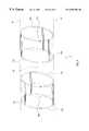
- FIG. 12Ais a partly cut-away perspective view of a cardiac catheter of the present invention in the retracted position thereof;
- FIG. 12Bis a perspective view of the catheter of FIG. 12A in the extended position thereof;
- FIG. 12Cis an end-on view of the catheter of FIG. 12A in the retracted position thereof;
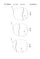
- FIG. 13Ais a partly cut-away side view of a second embodiment of the cardiac catheter of the present invention in the retracted and inflated position thereof;
- FIG. 13Bis an end-on view of the catheter of FIG. 13A in the retracted and inflated position thereof;
- FIG. 14is a partial perspective view of the C-mount fluoroscope of FIG. 9, including a magnetically permeable compensator;
- FIG. 15is a partial exploded perspective view of a preferred embodiment of the probe and receiver of FIG. 2A;
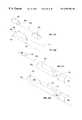
- FIG. 16illustrates a scheme for retrofitting an apparatus such as the receiver of FIG. 2A to a catheter.
- the present inventionis of a system and method for tracking the position and orientation of an object relative to a fixed frame of reference. Specifically, the present invention can be used to track the motion of a medical probe such as a catheter or an endoscope within the body of a patient.
- a medical probesuch as a catheter or an endoscope
- FIG. 1illustrates, in general terms, a system of the present invention.
- Receiver 14includes three field component sensors 16 , 18 , and 20 , each for sensing a different component of an electromagnetic field.
- Sensor 16includes two sensor elements 16 a and 16 b .
- Sensor 18includes two sensor elements 18 a and 18 b .
- Sensor 20includes two sensor elements 20 a and 20 b .
- the sensor elementsare coils, and the sensed components are independent magnetic field components.
- Sensor elements 16 a and 16 bare on opposite sides of, and equidistant from, a common reference point 22 .
- sensor elements 18 a and 18 bare on opposite sides of, and equidistant from, point 22
- sensor elements 20 a and 20 balso are on opposite sides of, and equidistant from, point 22 .
- sensors 16 , 18 and 20are disposed collinearly along a longitudinal axis 12 of probe 10 , but other configurations are possible, as discussed below.
- the system of FIG. 1also includes a transmitter 24 of electromagnetic radiation.
- Transmitter 24includes three substantially coplanar rectangular loop antennas 26 , 28 and 30 connected to driving circuitry 32 .
- Loop antennas 26 and 28are adjacent and are partly overlapped by loop antenna 30 .
- Driving circuitry 32includes appropriate signal generators and amplifiers for driving each of loop antennas 26 , 28 and 30 at a different frequency.
- the electromagnetic waves generated by transmitter 24are received by receiver 14 .
- the signals from receiver 14 that correspond to these electromagnetic wavesare sent to reception circuitry 34 that includes appropriate amplifiers and AID converters.
- Reception circuitry 34 and driving circuitry 32are controlled by a controller/processor 36 that typically is an appropriately programmed personal computer.
- Controller/processor 36directs the generation of transmitted signals by driving circuitry 32 and the reception of received signals by reception circuitry 34 . Controller/processor 36 also implements the algorithm described below to infer the position and orientation of probe 10 . Note that the system of FIG. 1 is a closed-loop system: the reception of signals from receiver 14 is synchronized with the transmission of electromagnetic waves by transmitter 24 .
- FIG. 2shows a particular, slightly modified embodiment of receiver 14 .
- FIG. 2Ais a perspective, partly cut away view of probe 10 with receiver 14 mounted in the housing 11 thereof
- FIG. 2Bis a circuit diagram of receiver 14 .
- sensor elements 16 a , 16 b , 18 a and 18 bare coils of conducting wire wound on ferrite cores 70 .
- Coils 16 a and 16 bare mutually parallel.
- Coils 18 a and 18 bare mutually parallel and are perpendicular to coils 16 a and 16 b .
- Coils 16 a , 16 b , 18 a and 18 ball are perpendicular to axis 12 .
- FIG. 2has a single coil 20 ′ of conducting wire wound on a ferrite core 70 .
- Coil 20 ′is parallel to axis 12 and therefore is perpendicular to coils 16 a , 16 b , 18 a and 18 b .
- Coil 20 ′is centered on reference point 22 .
- Sensors 16 , 18 and 20 ′are connected to reception circuitry 34 by twisted wire pairs 38 .
- coils 16 a and 16 bare connected in series, and coils 18 a and 18 b are connected in series.
- sensors 16 , 18 and 20 ′ of FIG. 2all measure field components at the same reference point 22 , coils 16 a , 16 b , 18 a , 18 b and 20 ′ can be wound on ferrite cores 70 instead of the air cores of WO 96/05768 without causing undue distortion of the received signals, despite the small transverse interior diameter 72 , typically less than two millimeters, of probe 10 when probe 10 is a catheter.
- FIG. 2Cis a circuit diagram that shows further features of the present invention that suppress this electromagnetic coupling.
- FIG. 2Cis drawn with particular reference to sensor 16 , but the same features apply, mutatis mutandis, to sensor 18 .
- Coils 16 a and 16 bare connected in series by inner leads 116 a and 116 b thereof.
- Outer lead 216 a of coil 16 ais connected, by wire 38 a of twisted wire pair 38 , to a positive input 126 a of a differential amplifier 128 of reception circuitry 34 .
- Outer lead 216 b of coil 16 bis connected, by wire 38 b of twisted wire pair 38 , to a negative input 126 b of differential amplifier 128 .
- Inner leads 116 a and 116 balso are connected to ground 124 by a wire 122 .
- wire 38 ais drawn as a solid line
- wire 38 bis drawn as a dotted line
- wire 122is drawn as a dashed line.
- FIG. 15is a partial exploded perspective view of a preferred embodiment of probe 10 and receiver 14 .
- Housing 11is substantially cylindrical, with two recesses 511 and 513 incised therein.
- the boundary of each recess 511 or 513includes a pair of diametrically opposed apertures: apertures 510 and 512 in the boundary of recess 511 and apertures 514 and 516 in the boundary of recess 513 .
- Arrows 530 and 532show two of the three components of a cylindrical coordinate system for describing position within and along housing 11 .
- Arrow 530points in the longitudinal direction.
- Arrow 532points in the azimuthal direction.
- Aperture pair 510 , 512is displaced both longitudinally and azimuthally from aperture pair 514 , 516 .
- Coil 16 ais a coil of electrically conducting wire that is wound about a core 70 a .
- Core 70 ais mounted in apertures 514 and 516 : end 518 of core 70 a , that extends beyond coil 16 a , is mounted in aperture 514 and is secured rigidly in place by a suitable glue, and end 520 of core 70 a , that extends beyond coil 16 a in the opposite direction, is mounted in aperture 516 and is secured rigidly in place by a suitable glue.
- coil 18 ais a coil of electrically conducting wire that is wound about a core 70 b .
- Core 70 bis mounted in apertures 510 and 512 : end 522 of core 70 b , that extends beyond coil 18 a , is mounted in aperture 510 and is secured rigidly in place by a suitable glue, and end 524 of core 70 b , that extends beyond coil 18 a in the opposite direction, is mounted in aperture 512 and is secured rigidly in place by a suitable glue.
- FIG. 15also shows the preferred azimuthal separation of aperture pair 514 , 516 from aperture pair 510 , 512 .
- Aperture pair 514 , 516is perpendicular to aperture pair 510 , 512 , in the sense that aperture pair 514 , 516 is displaced 90°, in the direction of arrow 532 , from aperture pair 510 , 512 .
- housing 11be made of a nonmagnetic metal such as nitinol, titanium, iconel, phynox or stainless steel. Housing 11 thus is sufficiently flexible to bend under the lateral forces of the walls of blood vessels through which probe 10 is inserted towards the body cavity, and sufficiently resilient to return to its unstressed shape, with coils 16 a and 18 a mutually perpendicular, when the portion of probe 10 that includes receiver 14 reaches the interior of the body cavity.
- housing 11does not distort the electromagnetic field sensed by receiver 14 despite the current eddies induced in housing 11 by the electromagnetic waves generated by transmitter 24 .
- Apertures 510 , 512 , 514 and 516are most conveniently formed by laser cutting.
- the accuracy of the mutual perpendicularity of coils 16 a and 18 a obtained in this mannerhas been found to be superior to the accuracy obtained by forming housing 11 as a solid cylindrical block and drilling mutually perpendicular recesses in the block to receive coils 16 a and 18 a.
- Coils 16 b and 18 bare mounted similarly in similar pairs of diametrically opposed, azimuthally and longitudinally displaced apertures. This ensures that coils 16 a and 16 b are mutually parallel, that coils 18 a and 18 b are mutually parallel, and that coils 16 b and 18 b are mutually perpendicular.
- housing 11is formed as an open, spring-like frame that includes apertures 510 , 512 , 514 and 516 in the form of small rings that are sized to accept the ends 518 , 520 , 522 and 524 of cores 70 a and 70 b .
- the spring-like nature of this embodiment of housing 11allows coils 16 a and 18 a to be mounted therein simply by forcing ends 518 , 520 , 522 and 524 into their respective apertures, and also allows housing 11 to flex during insertion towards a body cavity of a patient and to return to its unstressed shape upon arrival inside the body cavity.
- FIG. 3is an axial sectional view of receiver 14 mounted in a variant of probe 10 that has two sections 10 a and 10 b connected by a flexible connector 40 .
- sensors 16 and 18include sensor elements 16 a , 16 b , 18 a and 18 b that are coils of conducting wire wound on air cores and that are perpendicular to axis 12 .
- Sensor elements 16 a and 16 bare mutually parallel, sensor elements 18 a and 18 b are mutually parallel, and sensor elements 16 a and 16 b are perpendicular to sensor elements 18 a and 18 b .
- Sensor 20includes two sensor elements: coils 20 a and 20 b of conducting wire wound on air cores.
- Coils 20 a and 20 bare equidistant from reference point 22 and are parallel to axis 12 . Like coils 16 a and 16 b and like coils 18 a and 18 b , coils 20 a and 20 b are connected in series. Flexible connector 40 allows this variant of probe 10 to bend as this variant of probe 10 is moved within a medical patient. Sensor element pairs 16 , 18 and 20 are disposed symmetrically with respect to reference point 22 in the sense that when probe 10 of FIG.
- sensor elements 16 a and 16 bare on opposite sides of, and equidistant from, reference point 22 ; and likewise sensor elements 18 a and 18 b are on opposite sides of, and are equidistant from, reference point 22 ; and sensor elements 20 a and 20 b are on opposite sides of, and are equidistant from, reference point 22 .
- sensor elements 16 a , 16 b , 18 a , 18 b , 20 a and 20 ball are collinear, along axis 12 that intersects point 22 , and so are disposed symmetrically with respect to point 22 .
- Coil pairs 16 a and 16 bmay be used to measure a magnetic field component gradient at point 22 .
- coil pairs of identical helicitiesmay be used to measure magnetic field components if the top of one coil is connected to the bottom of the other coil.
- FIG. 5illustrates a second class of preferred embodiments of receiver 14 .
- a conceptual cylindrical surfaceis denoted by dashed lines 42 and dashed circles 44 .
- the embodiment of receiver 14 illustrated in FIG. 5includes three sensors 16 , 18 and 20 , each with two sensor elements 16 c and 16 d , 18 c and 18 d , and 20 c and 20 d , respectively.
- Each sensor elementis a flat rectangular coil, of many turns of conducting wire, that is bent into an arcuate shape to conform to the shape of the cylindrical surface.
- Sensor elements 16 c , 18 c and 20 care interleaved around circle 44 a .
- Sensor elements 16 d , 18 d and 20 dare interleaved around circle 44 b .
- Sensor elements 16 c and 16 dare disposed symmetrically with respect to reference point 22 , meaning that sensor elements 16 c and 16 d are on opposite sides of reference point 22 , are equidistant from reference point 22 , and are oriented so that an appropriate 180° rotation about point 22 maps sensor 16 c into sensor 16 d .
- sensor elements 18 c and 18 dare disposed symmetrically with respect to reference point 22
- sensor elements 20 c and 20 dare disposed symmetrically with respect to reference point 22 .
- Sensor elements 16 c and 16 dare connected in series, in a manner similar to sensor elements 16 a and 16 b , to respond to one component of the magnetic field.
- Sensor elements 18 c and 18 dare connected similarly in series to respond to a second component of the magnetic field that is independent of the first component, and sensor elements 20 c and 20 d are connected similarly in series to respond to a third component of the magnetic field that is independent of the first two components.
- sensor elements 16 c , 16 d , 18 c , 18 d , 20 c and 20 dare sized and separated so that these three magnetic field components are orthogonal.
- the cylindrical surface whereabout sensor elements 16 c , 16 d , 18 c , 18 d , 20 c and 20 d are disposedcould be the inner surface of probe 10 or the outer surface of a cylindrical sleeve adapted to fit inside probe 10 .
- sensor elements 16 c , 16 d , 18 c , 18 d , 20 c and 20 dmay be fabricated by any one of several standard methods, including photolithography and laser trimming.
- FIG. 10illustrates the preferred geometry of sensor elements 16 c , 16 d , 18 c , 18 d , 20 c and 20 d : a flat rectangular spiral 17 of an electrical conductor 19 . Only four turns are shown in spiral 17 , for illustrational simplicity. Preferably, however, there are several hundred turns in spiral 17 .
- a spiral 17intended for a cylindrical surface of a diameter of 1.6 millimeters, in which conductor 19 has a width of 0.25 microns, and in which the windings are separated by gaps of 0.25 microns, has 167 turns.
- FIGS. 12A, 12 B and 12 Cillustrate the distal end of a cardiac catheter 300 of the present invention.
- FIG. 12Ais a partly cut-away perspective view of catheter 300 in the retracted position thereof.
- FIG. 12Bis a perspective view of catheter 300 in the extended position thereof.
- FIG. 12Cis an end-on view of catheter 300 in the retracted position thereof.
- Catheter 300includes a flexible cylindrical inner sleeve 302 slidably mounted in a flexible cylindrical outer sleeve 304 .
- Connecting distal end 306 of inner sleeve 302 to distal end 308 of outer sleeve 304are four flexible rectangular strips 310 .
- Catheter 300includes a set of three orthogonal electromagnetic field component sensors 316 , 318 and 320 , in the manner of receiver 14 of FIG. 1 .
- First sensor 316includes coils 316 a and 316 b mounted on opposite lateral edges 312 a and 314 a of strip 310 a and on opposite lateral edges 312 c and 314 c of strip 310 c .
- Coil 316 ais mounted on lateral edges 312 a and 312 c .
- Coil 316 bis mounted on lateral edges 314 a and 314 b .
- Second sensor 318includes coils 318 a and 318 b mounted on opposite lateral edges 312 b and 314 b of strip 310 b and on opposite lateral edges 312 d and 314 d of strip 310 d .
- Coil 318 ais mounted on lateral edges 312 b and 312 d .
- Coil 318 bis mounted on lateral edges 314 b and 314 d .
- Third sensor 320includes coils 320 a and 320 b .
- Inner sleeve 302is cut away in FIG. 12A to show coils 320 a and 320 b . For illustrational clarity, the wires of coils 316 a and 318 a are shown in FIGS.
- each of coils 320 a and 320 bis about 1.1 mm long and about 1.1 mm in diameter and includes about 400 turns of 10 micron diameter copper wire.
- Coils 320 a and 320 bare parallel and equidistant from a central point 322 .
- catheter 300When catheter 300 is opened to the retracted position thereof, as shown in FIGS. 12A and 12C, the circular arcs formed by strips 310 are concentric with point 322 .
- catheter 300In the extended position thereof, catheter 300 is thin enough, preferably less than about 2 mm in diameter, to be inserted via the blood vessels of a patient into the patient's heart.
- inner sleeve 302is withdrawn relative to outer sleeve 304 to put catheter 300 in the retracted position thereof.
- Sensors 316 , 318 and 320are used in conjunction with transmitter 24 in the manner described below to determine the location and orientation of the distal end of catheter 300 within the patient's heart.
- Electrodes 326 and 328may be used for electrophysiologic mapping of the patient's heart. Alternatively, high RF power levels may be applied to selected heart tissue via electrode 328 to ablate that tissue in the treatment of conditions such as ventricular tachycardia.
- FIGS. 13A and 13Billustrate the distal end of an alternative embodiment 400 of the cardiac catheter of the present invention.
- FIG. 13Ais a partly cut-away side view of catheter 400 in the retracted position thereof.
- FIG. 13Bis an end-on view of catheter 400 in the retracted position thereof.
- catheter 400includes a flexible cylindrical inner sleeve 402 slidably mounted in a flexible cylindrical outer sleeve 404 .
- Connecting distal end 406 of inner sleeve 402 to distal end 408 of outer sleeve 404is a single flexible member: an inflatable latex balloon 410 .
- inner sleeve 402When inner sleeve 402 is in the extended position thereof relative to outer sleeve 404 , balloon 410 is flush against inner sleeve 402 .
- inner sleeve 402After the illustrated distal end of catheter 400 has been introduced to the targeted chamber of a patient's heart, inner sleeve 402 is withdrawn to the retracted position thereof, and balloon 410 is inflated to assume a spherical shape.
- catheter 400includes a set of three orthogonal electromagnetic field component sensors 416 , 418 and 420 , in the manner of receiver 14 of FIG. 1 .
- First sensor 416includes parallel coils 416 a and 416 b mounted as shown on outer surface 412 of balloon 410 .
- Second sensor 418includes parallel coils 418 a and 418 b mounted orthogonally to coils 416 a and 416 b on outer surface 412 , as shown.
- Third sensor 420includes coils 420 a and 420 b .
- Balloon 410 and inner sleeve 402are cut away in FIG. 13A to show coils 420 a and 420 b .
- Coils 420 a and 420 bare parallel and equidistant from a central point 422 .
- outer surface 412is a sphere concentric with point 422 . This makes coils 416 a , 416 b , 418 a and 418 b circular and concentric with point 422 , so that point 422 then becomes the reference point for electromagnetic field measurements.
- catheter 400includes four electrodes 426 , similar to electrodes 326 , mounted on outer surface 412 , and an electrode 428 , similar to electrode 328 , mounted on distal end 406 of inner sleeve 402 .
- FIG. 6is a plan view of loop antennas 26 , 28 and 30 .
- Loop antenna 26is a rectangle with legs 26 a , 26 b , 26 c and 26 d .
- Loop antenna 28is a rectangle of the same shape and size as loop antenna 26 , and with legs 28 a , 28 b , 28 c and 28 d .
- Legs 26 b and 28 dare adjacent.
- Loop antenna 30also is rectangular, with legs 30 a , 30 b , 30 c and 30 d .
- Loop antenna 46is of the same shape and size as loop antenna 30 , and overlaps the halves of loop antennas 26 and 28 that are not overlapped by loop antenna 30 .
- Loop antenna 48matches the outer perimeter defined by loop antennas 26 and 28 .
- loop antenna 48is energized using a sinusoidal current of angular frequency ⁇ 1 .
- loop antennas 26 and 28are energized by oppositely directed sinusoidal currents of angular frequency ⁇ 1 .
- loop antennas 30 and 46are energized by oppositely directed sinusoidal currents of angular frequency ⁇ 1 .
- the idea of this energization sequenceis to produce, first, a field above the transmitter that is spatially symmetric in both the horizontal and the vertical direction as seen in FIG.
- the signals output by the three sensors of receiver 14 in response to the electromagnetic waves so generatedare sampled at times tm by reception circuitry 34 .
- the sampled signalsare:
- Coefficients c 0 i,1 , c h i,1 and c v i,1are the in-phase amplitudes of the received signals.
- Coefficients c 0 i,2 , c h i,2 and c v i,2are the quadrature amplitudes of the received signals. Because ⁇ 1 is sufficiently low that receiver 14 is in the near fields generated by the loop antennas, in principle the quadrature amplitudes should be identically zero. Because of inevitable phase distortions, for example in reception circuitry 34 , the quadrature amplitudes generally are not zero.
- the sampled signals obtained by energizing loop antennas 26 , 28 and 30 separately with identical sinusoidal currents of angular frequency ⁇ 1are:
- s 1 imc 1 i cos ⁇ 1 t m +c 2 i sin ⁇ 1 t m from loop antenna 26
- loop antenna 48could also be emulated by identical currents flowing through loops 30 and 46 gives
- loop antennas 26 , 28 and 30are energized simultaneously with sinusoidal currents of angular frequencies ⁇ 1 , ⁇ 2 and ⁇ 3 , respectively.
- the sampled signalsnow are
- amplitudes c i1 and c i2refer to frequency ⁇ 1
- amplitudes c i3 and c i4refer to frequency ⁇ 2
- amplitudes c i5 and c i6refer to frequency ⁇ 3 .
- the sampled signalsare organized in a matrix s of three rows, one row for each sensor of receiver 14 , and as many columns as there are times t m , one column per time.
- Amplitudes c ijare organized in a matrix c of three rows and six columns.
- the matrices s and care related by a matrix A of six rows and as many columns as there are in matrix s:
- Right inverse matrix A ⁇ 1is not unique.
- a particular right inverse matrix A ⁇ 1may be selected by criteria that are well known in the art. For example, A ⁇ 1 may be the right inverse of A of smallest L 2 norm.
- matrix cis determined as the generalized inverse of equation (8):
- Equation (8)allows the sampling of the signals from receiver 14 at irregular times. Furthermore, there is no particular advantage to using frequencies ⁇ 1 , ⁇ 2 and ⁇ 3 that are integral multiples of a base frequency. Using closely spaced frequencies has the advantage of allowing the use of narrow-band filters in reception circuitry 34 , at the expense of the duration of the measurement having to be at least about 2 ⁇ / ⁇ , where ⁇ is the smallest frequency spacing, except in the special case of two signals of the same frequency and different phases.
- Tbe the orthonormal matrix that defines the rotation of probe 10 relative to the reference frame of transmitter 24 .
- T 0is an orthogonal matrix and E is in general a nonorthogonal matrix.
- T 0 and Eare functions of the position of probe 10 relative to the reference frame of transmitter 24 .
- T 0If T 0 is known, then T, and hence the orientation of probe 10 with respect to the reference frame of transmitter 24 , can be computed using equation (15).
- T 0may be determined by either of two different calibration procedures.
- probe 10is oriented so that T is a unit matrix, probe 10 is moved to a succession of positions relative to transmitter 24 , and M is measured at each position.
- the first variantexploits the principle of reciprocity.
- the sensor elementsare modeled as point sources, including as many terms in their multipole expansions as are necessary for accuracy, and their transmitted magnetic fields in the plane of transmitter 24 are calculated at a succession of positions relative thereto, also with probe 10 oriented so that T is a unit matrix.
- the EMF induced in the antennas of transmitter 24 by these time-varying magnetic fieldsis calculated using Faraday's law.
- the transfer function of reception circuitry 34then is used to compute M at each calibration position, and equation (16) gives T 0 at each calibration position.
- each antenna of transmitter 24 at the three frequencies ⁇ 1 , ⁇ 2 and ⁇ 3is modeled using the Biot-Savart law. Note that each frequency corresponds to a different sensor 16 , 18 or 20 .
- the signal received at each sensoris proportional to the projection of the magnetic field on the sensitivity direction of the sensor when object 10 is oriented so that T is a unit matrix. This gives the corresponding column of M up to a multiplicative constant and up to a correction based on the transfer function of reception circuitry 34 .
- a functional expression for T 0is fitted to the measured values of T 0 .
- this functional expressionis a polynomial. It has been found most preferable to express the Euler angles ⁇ , ⁇ and ⁇ that define T 0 as the following 36-term polynomials.
- AZcoe, ELcoe and RLcoeare 36-component vectors of the azimuth coefficients, elevation coefficients and roll coefficients that are fitted to the measured or calculated values of the Euler angles. Note that to fit these 36-component vectors, the calibration procedure must be carried out at at least 36 calibration positions. At each calibration position, W is computed from M using equation (13), and the position-like variables a, b and c are computed from Was above.
- Cartesian coordinates x, y and z of probe 10 relative to the reference frame of transmitter 24may be expressed as polynomials. It has been found most preferable to express x, y and z as the following 36-term polynomials:
- these position coordinate coefficientsare determined by either measuring or computing M at at least 36 calibration positions and fitting the resulting values of a, b and c to the known calibration values of x, y and z. Equations (17) through (22) may be used subsequently to infer the Cartesian coordinates and Euler angles of moving and rotating probe 10 noniteratively from measured values of M.
- FIGS. 7A, 7 B and 7 Cshow three alternative configurations of paired adjacent loop antennas 26 ′ and 28 ′.
- the arrowsindicate the direction of current flow that emulates a single loop antenna coincident with the outer perimeter of antennas 26 ′ and 28 ′.
- Other useful coplanar overlapping antenna configurationsare described in PCT Publication No. WO 96/03188, entitled “Computerized game Board”, which is incorporated by reference for all purposes as if fully set forth herein.
- FIG. 8is a schematic block diagram of driving circuitry 32 for driving a generic antenna 25 that represents any one of loop antennas 26 , 28 or 30 .
- a digital signal generator 50generates samples of a sinusoid that are converted to an analog signal by a D/A converter 52 . This analog signal is amplified by an amplifier 54 and sent to the positive input 60 of a differential amplifier 58 .
- Loop antenna 25is connected both to the output 64 of differential amplifier 58 and to the negative input 62 of differential amplifier 58 .
- Negative input 62also is grounded via a resistor 66 .
- the feedback loopthus set up drives antenna 25 at the frequency of the sinusoid generated by signal generator 50 , and makes antenna 25 appear to be an open circuit at all other frequencies.
- the circuitry of FIG. 8decouples loop antenna 25 from the other loop antennas.
- the superiority of the present invention over WO 97/36143is evident.
- WO 97/36143 and the present inventioncorrect for the mutual inductances of loop antenna 26 , radiating at a frequency ⁇ 1 , and loop antenna 30 , radiating at a frequency ⁇ 2 .
- the goalis to set up the field of frequency ⁇ 1 that would be present if only loop antenna 26 , and not loop antenna 30 , were present, and to set up the field of frequency ⁇ 2 that would be present if only loop antenna 30 , and not loop antenna 26 , were present.
- the time rate of change of the magnetic flux through loop antenna 26is proportional to the current through loop antenna 26
- the time rate of change of the magnetic flux through loop antenna 30is proportional to the current through loop antenna 30 .
- loop antenna 26sets up a certain time-varying magnetic flux of frequency ⁇ 1 across the area that would be bounded by loop antenna 30 if loop antenna 30 were present.
- the method of WO 97/36143forces the time rate of change of this magnetic flux through loop antenna 30 to be zero. Because the magnetic flux has no DC component, the magnetic flux itself through loop antenna 30 therefore also vanishes, which is contrary to the situation in the absence of loop antenna 30 .
- the present inventionmakes loop antenna 30 appear to be an open circuit at frequency ⁇ 1 and so does not change the magnetic flux from what it would be in the absence of loop antenna 30 .
- FIG. 9shows, schematically, a C-mount fluoroscope 80 modified according to the present invention for simultaneous real-time image acquisition and intrabody navigation.
- Fluoroscope 80includes the conventional components of a C-mount fluoroscope: an x-ray source 82 and an image acquisition module 84 mounted on opposite ends of a C-mount 78 , and a table 86 whereon the patient lies.
- Image acquisition module 84converting x-rays that transit the patient on table 86 into electronic signals representative of a 2D image of the patient.
- C-mount 78is pivotable about an axis 76 to allow the imaging of the patient from several angles, thereby allowing the reconstruction of a 3D image of the patient from successive 2D images.
- either a receiver 114similar to receiver 14 , or transmitter 24 , is rigidly mounted on C-mount 78 .
- Receiver 114 or transmitter 24serves to define a frame of reference that is fixed relative to C-mount 78 .
- the other components shown in FIG. 1, i.e., driving circuitry 32 , reception circuitry 34 , and control/processing unit 36are connected to transmitter 24 and to receiver 14 in probe 10 as described above in connection with FIG. 1 .
- signals from receiver 114 that correspond to the electromagnetic waves generated by transmitter 24 ′are sent to reception circuitry 134 that is identical to reception circuitry 34 , and controller/processor 36 directs the reception of received signals by reception circuitry 134 and the acquisition of an image of the patient by image acquisition module 84 of fluoroscope 80 .
- controller/processor 36determines the position and orientation of probe 10 relative to each acquired 2D image.
- the electromagnetic signalsare transmitted by a transmitter 24 ′ that is not attached to C-mount 78 , and controller/processor 36 determines the position and orientation of probe 10 relative to the 2D images by determining the positions and orientations of receivers 14 and 114 relative to transmitter 24 ′.
- Controller/processor 36synthesizes a combined image that includes both the 3D image of the patient acquired by fluoroscope 80 and an icon representing probe 10 positioned and oriented with respect to the 3D image of the patient in the same way as probe 10 is positioned and oriented with respect to the interior of the patient. Controller/processor 36 then displays this combined image on a monitor 92 .
- C-mount fluoroscope 80is illustrative rather than limitative.
- the scope of the present inventionincludes all suitable devices for acquiring 2D or 3D images of the interior of a patient, in modalities including CT, MRI and ultrasound in addition to fluoroscopy.
- FIG. 11shows a head 94 of a patient inside a (cut-away) CT scanner 98 .
- receiver 114 and transmitter 24are rigidly attached to CT scanner 98 , transmitter 24 being so attached via an arm 100 .
- CT scanner 98acquires 2D x-ray images of successive horizontal slices of head 94 .
- a receiver 214is rigidly mounted on head 94 using a headband 96 .
- the position and orientation of receiver 214 with respect to each imageis determined by the methods described above for determining the position and orientation of probe 10 with respect to the 2D images acquired by fluoroscope 80 .
- These positions and orientationsare stored, along with the 2D images, in control/processing unit 36 .
- the position and orientation of probe 10 in head 94is determined using signals from receivers 14 and 214 in the manner described above for positioning and orienting probe 10 with respect to C-mount 78 of fluoroscope 80 using receivers 14 and 114 .
- the position and orientation of probe 10 with respect to receiver 214 and the position and orientation of receiver 214 with respect to that 2D imageit is trivial to determine the position and orientation of probe 10 with respect to that 2D image.
- controller/processor 36now synthesizes a combined image that includes both the 3D image of head 94 acquired by CT scanner 98 and an icon representing probe 10 positioned and oriented with respect to the 3D image of head 94 in the same way as probe 10 is positioned and oriented with respect to head 94 . Controller/processor 36 then displays this combined image on monitor 92 .
- CT scanner 98is illustrative rather than limitative.
- the scope of the present inventionincludes all suitable devices for acquiring 2D or 3D images of a limb of a patient, in modalities including MRI, ultrasound and fluoroscopy in addition to CT. Note that this method of image acquisition followed by intrabody navigation allows the a centrally located imaging device to serve several medical treatment facilities.
- FIG. 14is a partially exploded, partial perspective view of a C-mount fluoroscope 80 ′ modified according to one aspect of the present invention.
- C-mount fluoroscope 80 ′includes an x-ray source 84 and an image acquisition module 82 at opposite ends of a C-mount 78 .
- Image acquisition module 82includes an image intensifier 83 , a front face 85 whereof faces x-ray source 84 , and a CCD camera 87 , mounted on the end of image intensifier 83 that is opposite front face 85 , for acquiring images that are intensified by image intensifier 83 .
- Image intensifier 83is housed in a cylindrical housing 91 .
- fluoroscope 80 ′includes an annular compensator 500 made of a magnetically permeable material such as mu-metal.
- front face 85is electrically conductive.
- the electromagnetic waves generated by transmitter 24 or 24 ′induce eddy currents in front face 85 that distort the electromagnetic field sensed by c;receiver 14 .
- Placing a mass of a magnetically permeable substance such as mu-metal in the proper spatial relationship with front face 85suppresses this distortion. This is taught, for example, in U.S. Pat. No. 5,760,335, to Gilboa, which patent is incorporated by reference for all purposes as if fully set forth herein, in the context of shielding a CRT from external radiation without perturbing the electromagnetic field external to the CRT.
- compensator 500is a ring, 5 cm in axial length, of mu metal foil 0.5 mm thick.
- Compensator 500is slidably mounted on the external surface 89 of cylindrical housing 91 , as indicated by double-headed arrows 504 , and is held in place by friction. It is straightforward for one ordinarily skilled in the art to select a position of compensator 500 on housing 91 that provides the optimal suppression of distortions of the electromagnetic field outside image intensifier 83 due to eddy currents in front face 85 .
- FIG. 16illustrates just such a retrofit capability, for adapting a satellite 550 to a substantially cylindrical catheter 552 for invasively probing or treating a body cavity such as a chamber of the heart.
- Satellite 550is an instrumentation capsule that may contain receiver 14 or any other medically useful apparatus.
- satellite 550may contain an apparatus for ablating cardiac tissue.
- a catheter such as catheter 552is introduced to the body cavity of a patient via the patient's blood vessels, via an introducer sheath. It is important that the external diameter of the introducer sheath be minimized, to reduce the risk of bleeding by the patient.
- any scheme for retrofitting satellite 550 to catheter 552must allow satellite 550 to be introduced into the introducer sheath along with catheter 552 . It is the latter requirement that generally precludes simply attaching satellite 550 to catheter 552 .
- satellite 550includes receiver 14 , with the intention of using receiver 14 to track the position and orientation of catheter 550 , then, when satellite 550 and catheter 552 are deployed within the body cavity, satellite 550 must have a fixed position and orientation relative to catheter 552 .
- FIG. 16Ashows a thin flexible tether 554 attached to proximal end 556 of satellite 550 .
- Tether 554provides a mechanical link to the outside of the patient.
- tether 554may also provide a communications link to the outside of the patient.
- satellite 550includes receiver 14
- extensions of wire pairs 38are included in tether 554 .
- Rigidly attached to tether 554is a hollow cylindrical sleeve 558 whose inner diameter is the same as the outer diameter of catheter 552 .
- FIG. 16 BThe remainder of the mechanism for reversibly securing satellite 550 to catheter 552 is shown in FIG. 16 B.
- Catheter 552is provided, near distal end 564 thereof, with a pocket 560 made of a flexible, resilient, elastic material. Pocket 560 is attached rigidly to the outer surface of catheter 552 .
- Pocket 560includes an aperture 562 , which is adjacent catheter 552 at the proximal end of catheter 552 , and which accommodates tether 554 .
- Pocket 560is sized to accommodate satellite 550 snugly therein via an opening in distal end 566 of pocket 560 .
- Satellite 550 , catheter 552 and the associated securing mechanismare assembled as shown in FIG. 16C, with tether 554 running through aperture 562 , sleeve 558 encircling catheter 552 proximal of pocket 560 , and satellite 550 distal of pocket 560 .
- Catheter 552 and tether 554are shown emerging from the distal end of a protective jacket 568 .
- sleeve 558is made of a low-friction material such as TeflonTM, to allows sleeve 558 to slide freely along catheter 552 .
- the assembly shown in FIG. 16Cis introduced to the introducer sheath with satellite 550 in front of catheter 552 .
- pocket 560is compressed against the outer surface of catheter 552 by the introducer sheath.
- Tether 554is sufficiently flexible to bend along with catheter 552 and jacket 568 as the assembly shown in FIG. 16C passes through the patient's blood vessels, but is sufficiently rigid to push satellite 550 ahead of distal end 564 of catheter 552 as catheter 552 is inserted into the patient.
- satellite 550 and distal end 564 of catheter 552reach the interior of the targeted body cavity in the configuration illustrated in FIG. 16 C.
- pocket 560opens, and tether 554 is pulled to withdraw satellite 550 into pocket 560 via the opening in distal end 566 of pocket 560 .
- Satellite 550 and tether 554now are held by pocket 560 , sleeve 558 and jacket 568 in a fixed position and orientation relative to catheter 552 , as illustrated in FIG. 16 D.
- tether 554is pushed to restore the configuration shown in FIG. 16C, to allow catheter 552 and satellite 550 to be withdrawn from the patient.
Landscapes
- Health & Medical Sciences (AREA)
- Life Sciences & Earth Sciences (AREA)
- Engineering & Computer Science (AREA)
- Surgery (AREA)
- Public Health (AREA)
- Veterinary Medicine (AREA)
- General Health & Medical Sciences (AREA)
- Biomedical Technology (AREA)
- Heart & Thoracic Surgery (AREA)
- Medical Informatics (AREA)
- Molecular Biology (AREA)
- Animal Behavior & Ethology (AREA)
- Physics & Mathematics (AREA)
- Pathology (AREA)
- Human Computer Interaction (AREA)
- Biophysics (AREA)
- Nuclear Medicine, Radiotherapy & Molecular Imaging (AREA)
- Robotics (AREA)
- Media Introduction/Drainage Providing Device (AREA)
- Measurement Of Length, Angles, Or The Like Using Electric Or Magnetic Means (AREA)
- Magnetic Resonance Imaging Apparatus (AREA)
- Ultra Sonic Daignosis Equipment (AREA)
- Apparatus For Radiation Diagnosis (AREA)
- Endoscopes (AREA)
- Measurement And Recording Of Electrical Phenomena And Electrical Characteristics Of The Living Body (AREA)
- Measuring And Recording Apparatus For Diagnosis (AREA)
- Measuring Magnetic Variables (AREA)
- Radar Systems Or Details Thereof (AREA)
Abstract
Description


Claims (53)
Priority Applications (5)
| Application Number | Priority Date | Filing Date | Title |
|---|---|---|---|
| US09/879,109US6947788B2 (en) | 1998-08-02 | 2001-06-13 | Navigable catheter |
| US09/879,108US20020005719A1 (en) | 1998-08-02 | 2001-06-13 | Intrabody navigation and imaging system for medical applications |
| US09/879,107US20010047133A1 (en) | 1998-08-02 | 2001-06-13 | Imaging device with magnetically permeable compensator |
| US10/397,358US6833814B2 (en) | 1998-08-02 | 2003-03-27 | Intrabody navigation system for medical applications |
| US10/408,123US7555330B2 (en) | 1998-08-02 | 2003-04-08 | Intrabody navigation system for medical applications |
Applications Claiming Priority (5)
| Application Number | Priority Date | Filing Date | Title |
|---|---|---|---|
| IL12562698AIL125626A0 (en) | 1998-08-02 | 1998-08-02 | Intrabody navigation system for medical applications |
| IL125626 | 1998-08-02 | ||
| IL12681498AIL126814A0 (en) | 1998-10-29 | 1998-10-29 | Intrabody navigation system for medical applications |
| IL126814 | 1998-10-29 | ||
| PCT/IL1999/000371WO2000010456A1 (en) | 1998-08-02 | 1999-07-07 | Intrabody navigation system for medical applications |
Related Parent Applications (1)
| Application Number | Title | Priority Date | Filing Date |
|---|---|---|---|
| PCT/IL1999/000371A-371-Of-InternationalWO2000010456A1 (en) | 1998-08-02 | 1999-07-07 | Intrabody navigation system for medical applications |
Related Child Applications (5)
| Application Number | Title | Priority Date | Filing Date |
|---|---|---|---|
| US09/879,108DivisionUS20020005719A1 (en) | 1998-08-02 | 2001-06-13 | Intrabody navigation and imaging system for medical applications |
| US09/879,107DivisionUS20010047133A1 (en) | 1998-08-02 | 2001-06-13 | Imaging device with magnetically permeable compensator |
| US09/879,109DivisionUS6947788B2 (en) | 1998-08-02 | 2001-06-13 | Navigable catheter |
| US10/397,358ContinuationUS6833814B2 (en) | 1998-08-02 | 2003-03-27 | Intrabody navigation system for medical applications |
| US10/408,123ContinuationUS7555330B2 (en) | 1998-08-02 | 2003-04-08 | Intrabody navigation system for medical applications |
Publications (1)
| Publication Number | Publication Date |
|---|---|
| US6593884B1true US6593884B1 (en) | 2003-07-15 |
Family
ID=26323687
Family Applications (6)
| Application Number | Title | Priority Date | Filing Date |
|---|---|---|---|
| US09/463,177Expired - LifetimeUS6593884B1 (en) | 1998-08-02 | 1999-07-07 | Intrabody navigation system for medical applications |
| US09/879,107AbandonedUS20010047133A1 (en) | 1998-08-02 | 2001-06-13 | Imaging device with magnetically permeable compensator |
| US09/879,108AbandonedUS20020005719A1 (en) | 1998-08-02 | 2001-06-13 | Intrabody navigation and imaging system for medical applications |
| US09/879,109Expired - LifetimeUS6947788B2 (en) | 1998-08-02 | 2001-06-13 | Navigable catheter |
| US10/397,358Expired - LifetimeUS6833814B2 (en) | 1998-08-02 | 2003-03-27 | Intrabody navigation system for medical applications |
| US10/408,123Expired - Fee RelatedUS7555330B2 (en) | 1998-08-02 | 2003-04-08 | Intrabody navigation system for medical applications |
Family Applications After (5)
| Application Number | Title | Priority Date | Filing Date |
|---|---|---|---|
| US09/879,107AbandonedUS20010047133A1 (en) | 1998-08-02 | 2001-06-13 | Imaging device with magnetically permeable compensator |
| US09/879,108AbandonedUS20020005719A1 (en) | 1998-08-02 | 2001-06-13 | Intrabody navigation and imaging system for medical applications |
| US09/879,109Expired - LifetimeUS6947788B2 (en) | 1998-08-02 | 2001-06-13 | Navigable catheter |
| US10/397,358Expired - LifetimeUS6833814B2 (en) | 1998-08-02 | 2003-03-27 | Intrabody navigation system for medical applications |
| US10/408,123Expired - Fee RelatedUS7555330B2 (en) | 1998-08-02 | 2003-04-08 | Intrabody navigation system for medical applications |
Country Status (6)
| Country | Link |
|---|---|
| US (6) | US6593884B1 (en) |
| EP (3) | EP2279692A3 (en) |
| JP (5) | JP2003524443A (en) |
| AU (1) | AU4644799A (en) |
| DE (1) | DE69939471D1 (en) |
| WO (1) | WO2000010456A1 (en) |
Cited By (272)
| Publication number | Priority date | Publication date | Assignee | Title |
|---|---|---|---|---|
| US20030050557A1 (en)* | 1998-11-04 | 2003-03-13 | Susil Robert C. | Systems and methods for magnetic-resonance-guided interventional procedures |
| US20030097064A1 (en)* | 2001-11-13 | 2003-05-22 | Dnyanesh Talpade | Impedance-matching apparatus and construction for intravascular device |
| US20030160721A1 (en)* | 1998-08-02 | 2003-08-28 | Pinhas Gilboa | Intrabody navigation system for medical applications |
| US20040046557A1 (en)* | 2002-05-29 | 2004-03-11 | Parag Karmarkar | Magnetic resonance probes |
| US20040178790A1 (en)* | 2003-03-14 | 2004-09-16 | Gifford Carl B. | Eddy current probe and associated inspection method |
| US20040193057A1 (en)* | 2003-03-28 | 2004-09-30 | Scimed Life Systems, Inc. | Imaging transducer assembly |
| US20040207661A1 (en)* | 2002-12-27 | 2004-10-21 | Kabushiki Kaisha Toshiba | Medical imaging apparatus which displays predetermined information in differentiable manner from others |
| US6812700B2 (en)* | 2002-08-05 | 2004-11-02 | The Board Of Trustees Of The Leland Stanford Junior University | Correction of local field inhomogeneity in magnetic resonance imaging apparatus |
| US20050062469A1 (en)* | 2003-09-23 | 2005-03-24 | Anderson Peter Traneus | System and method for hemisphere disambiguation in electromagnetic tracking systems |
| US20050103334A1 (en)* | 2000-12-02 | 2005-05-19 | Bonutti Peter M. | Medicant delivery system and method |
| US20050251032A1 (en)* | 2004-05-06 | 2005-11-10 | Scimed Life Systems, Inc. | Intravascular antenna |
| US20050251031A1 (en)* | 2004-05-06 | 2005-11-10 | Scimed Life Systems, Inc. | Apparatus and construction for intravascular device |
| US20060025678A1 (en)* | 2004-07-26 | 2006-02-02 | Peter Speier | Method and apparatus for determining the azimuthal orientation of a medical instrument from MR signals |
| US20060173299A1 (en)* | 2004-12-14 | 2006-08-03 | Scimed Life Systems, Inc. | Systems and methods for improved three-dimensional imaging of a body lumen |
| US20060247683A1 (en)* | 2005-04-21 | 2006-11-02 | Asthmatx, Inc. | Control systems for delivering energy |
| WO2006124474A2 (en) | 2005-05-13 | 2006-11-23 | Boston Scientific Limited | Endoscopic apparatus with integrated variceal ligation device |
| US20060262631A1 (en)* | 2004-11-12 | 2006-11-23 | Samsung Electronics Co., Ltd. | Bank selection signal control circuit for use in semiconductor memory device, and bank selection control method |
| US20070013710A1 (en)* | 2005-05-23 | 2007-01-18 | Higgins William E | Fast 3D-2D image registration method with application to continuously guided endoscopy |
| US20070015997A1 (en)* | 2005-05-23 | 2007-01-18 | Higgins William E | Guidance method based on 3D-2D pose estimation and 3D-CT registration with application to live bronchoscopy |
| US20070055090A1 (en)* | 2004-08-12 | 2007-03-08 | Navotek Medical Ltd. | Medical Treatment System and Method |
| US20070205373A1 (en)* | 2004-08-12 | 2007-09-06 | Navotek Medical Ltd. | Localization of a Radioactive Source Within a Body of a Subject |
| US20070299352A1 (en)* | 2006-06-13 | 2007-12-27 | Doron Harlev | Non-contact cardiac mapping, including moving catheter and multi-beat integration |
| US20070299353A1 (en)* | 2006-06-13 | 2007-12-27 | Doron Harlev | Non-contact cardiac mapping, including preprocessing |
| US20070299351A1 (en)* | 2006-06-13 | 2007-12-27 | Doron Harlev | Non-contact cardiac mapping, including resolution map |
| US20080009760A1 (en)* | 2006-06-30 | 2008-01-10 | Broncus Technologies, Inc. | Airway bypass site selection and treatment planning |
| US20080118116A1 (en)* | 2006-11-20 | 2008-05-22 | General Electric Company | Systems and methods for tracking a surgical instrument and for conveying tracking information via a network |
| US20080132757A1 (en)* | 2006-12-01 | 2008-06-05 | General Electric Company | System and Method for Performing Minimally Invasive Surgery Using a Multi-Channel Catheter |
| US20080139929A1 (en)* | 2006-12-06 | 2008-06-12 | General Electric Company | System and method for tracking an invasive surgical instrument while imaging a patient |
| US7412276B2 (en) | 1998-11-04 | 2008-08-12 | Johns Hopkins University School Of Medicine | Brain therapy |
| US20080207997A1 (en)* | 2007-01-31 | 2008-08-28 | The Penn State Research Foundation | Method and apparatus for continuous guidance of endoscopy |
| US20080262473A1 (en)* | 2004-10-19 | 2008-10-23 | Navotek Medical Ltd. | Locating a Catheter Tip Using a Tracked Guide |
| US7525309B2 (en) | 2005-12-30 | 2009-04-28 | Depuy Products, Inc. | Magnetic sensor array |
| US20090107511A1 (en)* | 2006-05-11 | 2009-04-30 | Yossi Gross | Implantable respiration therapy device |
| US20090127459A1 (en)* | 2004-08-12 | 2009-05-21 | Navotek Medical Ltd. | Localization of a Radioactive Source |
| US20090131734A1 (en)* | 2006-02-16 | 2009-05-21 | Navotek Medical Ltd. | Implantable medical marker and methods of preparation thereof |
| US20090156895A1 (en)* | 2007-01-31 | 2009-06-18 | The Penn State Research Foundation | Precise endoscopic planning and visualization |
| WO2009074872A2 (en) | 2007-07-09 | 2009-06-18 | Superdimension, Ltd. | Patent breathing modeling |
| US20090171187A1 (en)* | 2007-12-26 | 2009-07-02 | Gerhart John P | Catheter electrode that can simultaneously emit electrical energy and facilitate visualization by magnetic resonance imaging |
| US20090171188A1 (en)* | 2007-12-28 | 2009-07-02 | Saurav Paul | Flexible polymer electrode for mri-guided positioning and radio frequency ablation |
| US7599730B2 (en)* | 2002-11-19 | 2009-10-06 | Medtronic Navigation, Inc. | Navigation system for cardiac therapies |
| US20090253976A1 (en)* | 2008-04-02 | 2009-10-08 | Rhythmia Medical, Inc. | Intracardiac Tracking System |
| US20090281419A1 (en)* | 2006-06-22 | 2009-11-12 | Volker Troesken | System for determining the position of a medical instrument |
| WO2009147671A1 (en) | 2008-06-03 | 2009-12-10 | Superdimension Ltd. | Feature-based registration method |
| US20100008555A1 (en)* | 2008-05-15 | 2010-01-14 | Superdimension, Ltd. | Automatic Pathway And Waypoint Generation And Navigation Method |
| US20100034449A1 (en)* | 2008-06-06 | 2010-02-11 | Superdimension, Ltd. | Hybrid Registration Method |
| US20100041949A1 (en)* | 2007-03-12 | 2010-02-18 | David Tolkowsky | Devices and methods for performing medical procedures in tree-like luminal structures |
| US20100042041A1 (en)* | 2008-08-18 | 2010-02-18 | Navotek Medical Ltd. | Implantation device for soft tissue markers and other implants |
| US7697972B2 (en) | 2002-11-19 | 2010-04-13 | Medtronic Navigation, Inc. | Navigation system for cardiac therapies |
| US20100106154A1 (en)* | 2008-10-27 | 2010-04-29 | Rhythmia Medical, Inc. | Tracking System Using Field Mapping |
| US7722565B2 (en) | 2004-11-05 | 2010-05-25 | Traxtal, Inc. | Access system |
| WO2010071895A1 (en) | 2008-12-19 | 2010-06-24 | Superdimension, Ltd. | Navigable tissue treatment tools |
| US20100160772A1 (en)* | 2008-12-18 | 2010-06-24 | Medtronic, Inc. | Adaptable Image Guided Delivery System |
| US7751868B2 (en) | 2004-11-12 | 2010-07-06 | Philips Electronics Ltd | Integrated skin-mounted multifunction device for use in image-guided surgery |
| US7797032B2 (en)* | 1999-10-28 | 2010-09-14 | Medtronic Navigation, Inc. | Method and system for navigating a catheter probe in the presence of field-influencing objects |
| US7794407B2 (en) | 2006-10-23 | 2010-09-14 | Bard Access Systems, Inc. | Method of locating the tip of a central venous catheter |
| US7805269B2 (en) | 2004-11-12 | 2010-09-28 | Philips Electronics Ltd | Device and method for ensuring the accuracy of a tracking device in a volume |
| EP2238901A2 (en) | 2009-04-08 | 2010-10-13 | Superdimension, LTD. | Locatable catheter |
| US20100274150A1 (en)* | 2009-04-23 | 2010-10-28 | Rhythmia Medical, Inc. | Multi-Electrode Mapping System |
| US20100286551A1 (en)* | 2009-05-08 | 2010-11-11 | Rhythmia Medical, Inc. | Impedance Based Anatomy Generation |
| US20100286550A1 (en)* | 2009-05-08 | 2010-11-11 | Rhythmia Medical, Inc. | Impedance Based Anatomy Generation |
| US7835780B1 (en)* | 2000-03-30 | 2010-11-16 | Duerk Jeffrey L | MR invasive device and method for active MR guidance of invasive devices with target navigation |
| US7840254B2 (en) | 2005-01-18 | 2010-11-23 | Philips Electronics Ltd | Electromagnetically tracked K-wire device |
| EP2253287A2 (en) | 2009-05-14 | 2010-11-24 | superDimension Ltd. | Automatic registration technique |
| US20100324414A1 (en)* | 2007-02-08 | 2010-12-23 | Rhythmia Medical, Inc., A Delaware Corporation | Catheter tracking and endocardium representation generation |
| US7860556B2 (en) | 2005-02-02 | 2010-12-28 | Voyage Medical, Inc. | Tissue imaging and extraction systems |
| US7860555B2 (en) | 2005-02-02 | 2010-12-28 | Voyage Medical, Inc. | Tissue visualization and manipulation system |
| US20110060185A1 (en)* | 2009-06-01 | 2011-03-10 | Olympus Medical Systems Corp. | Medical device system and calibration method for medical instrument |
| US7912531B1 (en)* | 2003-12-17 | 2011-03-22 | Advanced Cardiovascular Systems, Inc. | Magnetic resonance imaging coils |
| US7918787B2 (en) | 2005-02-02 | 2011-04-05 | Voyage Medical, Inc. | Tissue visualization and manipulation systems |
| US7930016B1 (en) | 2005-02-02 | 2011-04-19 | Voyage Medical, Inc. | Tissue closure system |
| US7985254B2 (en) | 2007-01-08 | 2011-07-26 | David Tolkowsky | Endobronchial fluid exhaler devices and methods for use thereof |
| US7998062B2 (en) | 2004-03-29 | 2011-08-16 | Superdimension, Ltd. | Endoscope structures and techniques for navigating to a target in branched structure |
| US20110206253A1 (en)* | 2010-02-01 | 2011-08-25 | Superdimension, Ltd. | Region-Growing Algorithm |
| US8050746B2 (en) | 2005-02-02 | 2011-11-01 | Voyage Medical, Inc. | Tissue visualization device and method variations |
| US20110270083A1 (en)* | 2008-12-30 | 2011-11-03 | Koninklijke Philips Electronics N.V. | System and method for dynamic metal distortion compensation for electromagnetic tracking systems |
| US8068648B2 (en) | 2006-12-21 | 2011-11-29 | Depuy Products, Inc. | Method and system for registering a bone of a patient with a computer assisted orthopaedic surgery system |
| US8078266B2 (en) | 2005-10-25 | 2011-12-13 | Voyage Medical, Inc. | Flow reduction hood systems |
| EP2401956A1 (en) | 2008-07-10 | 2012-01-04 | Superdimension Ltd. | Integrated multi-functional endoscopic tool |
| US8095224B2 (en) | 2009-03-19 | 2012-01-10 | Greatbatch Ltd. | EMI shielded conduit assembly for an active implantable medical device |
| US8131350B2 (en) | 2006-12-21 | 2012-03-06 | Voyage Medical, Inc. | Stabilization of visualization catheters |
| US8137333B2 (en) | 2005-10-25 | 2012-03-20 | Voyage Medical, Inc. | Delivery of biological compounds to ischemic and/or infarcted tissue |
| US8175681B2 (en) | 2008-12-16 | 2012-05-08 | Medtronic Navigation Inc. | Combination of electromagnetic and electropotential localization |
| US8219208B2 (en) | 2001-04-13 | 2012-07-10 | Greatbatch Ltd. | Frequency selective passive component networks for active implantable medical devices utilizing an energy dissipating surface |
| US8221310B2 (en) | 2005-10-25 | 2012-07-17 | Voyage Medical, Inc. | Tissue visualization device and method variations |
| US8235985B2 (en) | 2007-08-31 | 2012-08-07 | Voyage Medical, Inc. | Visualization and ablation system variations |
| US8275466B2 (en) | 2006-06-08 | 2012-09-25 | Greatbatch Ltd. | Band stop filter employing a capacitor and an inductor tank circuit to enhance MRI compatibility of active medical devices |
| US8333012B2 (en) | 2008-10-10 | 2012-12-18 | Voyage Medical, Inc. | Method of forming electrode placement and connection systems |
| US8369930B2 (en) | 2009-06-16 | 2013-02-05 | MRI Interventions, Inc. | MRI-guided devices and MRI-guided interventional systems that can track and generate dynamic visualizations of the devices in near real time |
| US8391952B2 (en) | 2007-10-11 | 2013-03-05 | General Electric Company | Coil arrangement for an electromagnetic tracking system |
| US8388546B2 (en) | 2006-10-23 | 2013-03-05 | Bard Access Systems, Inc. | Method of locating the tip of a central venous catheter |
| US8388541B2 (en) | 2007-11-26 | 2013-03-05 | C. R. Bard, Inc. | Integrated system for intravascular placement of a catheter |
| US8437833B2 (en) | 2008-10-07 | 2013-05-07 | Bard Access Systems, Inc. | Percutaneous magnetic gastrostomy |
| US8447414B2 (en) | 2008-12-17 | 2013-05-21 | Greatbatch Ltd. | Switched safety protection circuit for an AIMD system during exposure to high power electromagnetic fields |
| US8457760B2 (en) | 2001-04-13 | 2013-06-04 | Greatbatch Ltd. | Switched diverter circuits for minimizing heating of an implanted lead and/or providing EMI protection in a high power electromagnetic field environment |
| US8478382B2 (en) | 2008-02-11 | 2013-07-02 | C. R. Bard, Inc. | Systems and methods for positioning a catheter |
| WO2013098715A1 (en) | 2011-12-30 | 2013-07-04 | Mediguide Ltd | Roll detection and six degrees of freedom sensor assembly |
| US8494613B2 (en) | 2009-08-31 | 2013-07-23 | Medtronic, Inc. | Combination localization system |
| US8494614B2 (en) | 2009-08-31 | 2013-07-23 | Regents Of The University Of Minnesota | Combination localization system |
| US8509913B2 (en) | 2001-04-13 | 2013-08-13 | Greatbatch Ltd. | Switched diverter circuits for minimizing heating of an implanted lead and/or providing EMI protection in a high power electromagnetic field environment |
| US8600519B2 (en) | 2001-04-13 | 2013-12-03 | Greatbatch Ltd. | Transient voltage/current protection system for electronic circuits associated with implanted leads |
| US8611983B2 (en) | 2005-01-18 | 2013-12-17 | Philips Electronics Ltd | Method and apparatus for guiding an instrument to a target in the lung |
| US8608724B2 (en) | 2004-07-19 | 2013-12-17 | Broncus Medical Inc. | Devices for delivering substances through an extra-anatomic opening created in an airway |
| US8632461B2 (en) | 2005-06-21 | 2014-01-21 | Koninklijke Philips N.V. | System, method and apparatus for navigated therapy and diagnosis |
| USD699359S1 (en) | 2011-08-09 | 2014-02-11 | C. R. Bard, Inc. | Ultrasound probe head |
| US8657805B2 (en) | 2007-05-08 | 2014-02-25 | Intuitive Surgical Operations, Inc. | Complex shape steerable tissue visualization and manipulation catheter |
| US8663088B2 (en) | 2003-09-15 | 2014-03-04 | Covidien Lp | System of accessories for use with bronchoscopes |
| US8694074B2 (en) | 2010-05-11 | 2014-04-08 | Rhythmia Medical, Inc. | Electrode displacement determination |
| US8694071B2 (en) | 2010-02-12 | 2014-04-08 | Intuitive Surgical Operations, Inc. | Image stabilization techniques and methods |
| US8709034B2 (en) | 2011-05-13 | 2014-04-29 | Broncus Medical Inc. | Methods and devices for diagnosing, monitoring, or treating medical conditions through an opening through an airway wall |
| US8709008B2 (en) | 2007-05-11 | 2014-04-29 | Intuitive Surgical Operations, Inc. | Visual electrode ablation systems |
| US8758229B2 (en) | 2006-12-21 | 2014-06-24 | Intuitive Surgical Operations, Inc. | Axial visualization systems |
| US8764725B2 (en) | 2004-02-09 | 2014-07-01 | Covidien Lp | Directional anchoring mechanism, method and applications thereof |
| US8781555B2 (en) | 2007-11-26 | 2014-07-15 | C. R. Bard, Inc. | System for placement of a catheter including a signal-generating stylet |
| US8784336B2 (en) | 2005-08-24 | 2014-07-22 | C. R. Bard, Inc. | Stylet apparatuses and methods of manufacture |
| US8801693B2 (en) | 2010-10-29 | 2014-08-12 | C. R. Bard, Inc. | Bioimpedance-assisted placement of a medical device |
| US8849382B2 (en) | 2007-11-26 | 2014-09-30 | C. R. Bard, Inc. | Apparatus and display methods relating to intravascular placement of a catheter |
| US8862200B2 (en) | 2005-12-30 | 2014-10-14 | DePuy Synthes Products, LLC | Method for determining a position of a magnetic source |
| US8858609B2 (en) | 2008-02-07 | 2014-10-14 | Intuitive Surgical Operations, Inc. | Stent delivery under direct visualization |
| US8882763B2 (en) | 2010-01-12 | 2014-11-11 | Greatbatch Ltd. | Patient attached bonding strap for energy dissipation from a probe or a catheter during magnetic resonance imaging |
| US8903505B2 (en) | 2006-06-08 | 2014-12-02 | Greatbatch Ltd. | Implantable lead bandstop filter employing an inductive coil with parasitic capacitance to enhance MRI compatibility of active medical devices |
| US8905920B2 (en) | 2007-09-27 | 2014-12-09 | Covidien Lp | Bronchoscope adapter and method |
| US8934962B2 (en) | 2005-02-02 | 2015-01-13 | Intuitive Surgical Operations, Inc. | Electrophysiology mapping and visualization system |
| US8977355B2 (en) | 2001-04-13 | 2015-03-10 | Greatbatch Ltd. | EMI filter employing a capacitor and an inductor tank circuit having optimum component values |
| USD724745S1 (en) | 2011-08-09 | 2015-03-17 | C. R. Bard, Inc. | Cap for an ultrasound probe |
| US8989870B2 (en) | 2001-04-13 | 2015-03-24 | Greatbatch Ltd. | Tuned energy balanced system for minimizing heating and/or to provide EMI protection of implanted leads in a high power electromagnetic field environment |
| US9002442B2 (en) | 2011-01-13 | 2015-04-07 | Rhythmia Medical, Inc. | Beat alignment and selection for cardiac mapping |
| US9014851B2 (en) | 2013-03-15 | 2015-04-21 | Hansen Medical, Inc. | Systems and methods for tracking robotically controlled medical instruments |
| US9037215B2 (en) | 2007-01-31 | 2015-05-19 | The Penn State Research Foundation | Methods and apparatus for 3D route planning through hollow organs |
| US9057600B2 (en) | 2013-03-13 | 2015-06-16 | Hansen Medical, Inc. | Reducing incremental measurement sensor error |
| US9055881B2 (en) | 2004-04-26 | 2015-06-16 | Super Dimension Ltd. | System and method for image-based alignment of an endoscope |
| US9055906B2 (en) | 2006-06-14 | 2015-06-16 | Intuitive Surgical Operations, Inc. | In-vivo visualization systems |
| US9101735B2 (en) | 2008-07-07 | 2015-08-11 | Intuitive Surgical Operations, Inc. | Catheter control systems |
| US9108066B2 (en) | 2008-03-20 | 2015-08-18 | Greatbatch Ltd. | Low impedance oxide resistant grounded capacitor for an AIMD |
| US9125578B2 (en) | 2009-06-12 | 2015-09-08 | Bard Access Systems, Inc. | Apparatus and method for catheter navigation and tip location |
| US9138166B2 (en) | 2011-07-29 | 2015-09-22 | Hansen Medical, Inc. | Apparatus and methods for fiber integration and registration |
| US9138165B2 (en) | 2012-02-22 | 2015-09-22 | Veran Medical Technologies, Inc. | Systems, methods and devices for forming respiratory-gated point cloud for four dimensional soft tissue navigation |
| US9155452B2 (en) | 2007-04-27 | 2015-10-13 | Intuitive Surgical Operations, Inc. | Complex shape steerable tissue visualization and manipulation catheter |
| US9204820B2 (en) | 2012-12-31 | 2015-12-08 | Biosense Webster (Israel) Ltd. | Catheter with combined position and pressure sensing structures |
| US9204841B2 (en) | 2012-12-31 | 2015-12-08 | Biosense Webster (Israel) Ltd. | Catheter with serially connected sensing structures and methods of calibration and detection |
| US9211107B2 (en) | 2011-11-07 | 2015-12-15 | C. R. Bard, Inc. | Ruggedized ultrasound hydrogel insert |
| US9218663B2 (en) | 2005-09-13 | 2015-12-22 | Veran Medical Technologies, Inc. | Apparatus and method for automatic image guided accuracy verification |
| US9242090B2 (en) | 2001-04-13 | 2016-01-26 | MRI Interventions Inc. | MRI compatible medical leads |
| USD748297S1 (en)* | 2013-12-02 | 2016-01-26 | Bonshine Optical Electron Technology Co., Ltd. | LED bulb |
| US9248283B2 (en) | 2001-04-13 | 2016-02-02 | Greatbatch Ltd. | Band stop filter comprising an inductive component disposed in a lead wire in series with an electrode |
| US9259290B2 (en) | 2009-06-08 | 2016-02-16 | MRI Interventions, Inc. | MRI-guided surgical systems with proximity alerts |
| US9271663B2 (en) | 2013-03-15 | 2016-03-01 | Hansen Medical, Inc. | Flexible instrument localization from both remote and elongation sensors |
| US9277872B2 (en) | 2011-01-13 | 2016-03-08 | Rhythmia Medical, Inc. | Electroanatomical mapping |
| US9295828B2 (en) | 2001-04-13 | 2016-03-29 | Greatbatch Ltd. | Self-resonant inductor wound portion of an implantable lead for enhanced MRI compatibility of active implantable medical devices |
| US9339206B2 (en) | 2009-06-12 | 2016-05-17 | Bard Access Systems, Inc. | Adaptor for endovascular electrocardiography |
| US9345532B2 (en) | 2011-05-13 | 2016-05-24 | Broncus Medical Inc. | Methods and devices for ablation of tissue |
| US9398892B2 (en) | 2005-06-21 | 2016-07-26 | Koninklijke Philips N.V. | Device and method for a trackable ultrasound |
| US9427596B2 (en) | 2013-01-16 | 2016-08-30 | Greatbatch Ltd. | Low impedance oxide resistant grounded capacitor for an AIMD |
| US9445734B2 (en) | 2009-06-12 | 2016-09-20 | Bard Access Systems, Inc. | Devices and methods for endovascular electrography |
| US20160278852A1 (en)* | 2013-12-12 | 2016-09-29 | St. Jude Medical, Cardiology Division, Inc. | Medical device with contact force sensing tip |
| US9456766B2 (en) | 2007-11-26 | 2016-10-04 | C. R. Bard, Inc. | Apparatus for use with needle insertion guidance system |
| US9468397B2 (en) | 2013-01-23 | 2016-10-18 | St. Jude Medical, Atrial Fibrillation Division, Inc. | Distributed location sensor |
| US9468364B2 (en) | 2008-11-14 | 2016-10-18 | Intuitive Surgical Operations, Inc. | Intravascular catheter with hood and image processing systems |
| US9492097B2 (en) | 2007-11-26 | 2016-11-15 | C. R. Bard, Inc. | Needle length determination and calibration for insertion guidance system |
| US9510732B2 (en) | 2005-10-25 | 2016-12-06 | Intuitive Surgical Operations, Inc. | Methods and apparatus for efficient purging |
| US9521961B2 (en) | 2007-11-26 | 2016-12-20 | C. R. Bard, Inc. | Systems and methods for guiding a medical instrument |
| US9533128B2 (en) | 2003-07-18 | 2017-01-03 | Broncus Medical Inc. | Devices for maintaining patency of surgically created channels in tissue |
| US9532724B2 (en) | 2009-06-12 | 2017-01-03 | Bard Access Systems, Inc. | Apparatus and method for catheter navigation using endovascular energy mapping |
| US9554716B2 (en) | 2007-11-26 | 2017-01-31 | C. R. Bard, Inc. | Insertion guidance system for needles and medical components |
| WO2017017659A1 (en) | 2015-07-30 | 2017-02-02 | St. Jude Medical International Holding S.A R.L. | Roll-sensing sensor assembly |
| US9575140B2 (en) | 2008-04-03 | 2017-02-21 | Covidien Lp | Magnetic interference detection system and method |
| US9585588B2 (en) | 2014-06-03 | 2017-03-07 | Boston Scientific Scimed, Inc. | Electrode assembly having an atraumatic distal tip |
| US9636031B2 (en) | 2007-11-26 | 2017-05-02 | C.R. Bard, Inc. | Stylets for use with apparatus for intravascular placement of a catheter |
| US9636032B2 (en) | 2013-05-06 | 2017-05-02 | Boston Scientific Scimed Inc. | Persistent display of nearest beat characteristics during real-time or play-back electrophysiology data visualization |
| US9649048B2 (en) | 2007-11-26 | 2017-05-16 | C. R. Bard, Inc. | Systems and methods for breaching a sterile field for intravascular placement of a catheter |
| US9661991B2 (en) | 2005-08-24 | 2017-05-30 | Koninklijke Philips N.V. | System, method and devices for navigated flexible endoscopy |
| US9675424B2 (en) | 2001-06-04 | 2017-06-13 | Surgical Navigation Technologies, Inc. | Method for calibrating a navigation system |
| US9687166B2 (en) | 2013-10-14 | 2017-06-27 | Boston Scientific Scimed, Inc. | High resolution cardiac mapping electrode array catheter |
| US20170209073A1 (en)* | 2016-01-26 | 2017-07-27 | Auris Surgical Robotics, Inc. | Surgical tools having electromagnetic tracking components |
| US9814522B2 (en) | 2010-04-06 | 2017-11-14 | Intuitive Surgical Operations, Inc. | Apparatus and methods for ablation efficacy |
| US9839372B2 (en) | 2014-02-06 | 2017-12-12 | C. R. Bard, Inc. | Systems and methods for guidance and placement of an intravascular device |
| US9848795B2 (en) | 2014-06-04 | 2017-12-26 | Boston Scientific Scimed Inc. | Electrode assembly |
| EP3260042A1 (en) | 2006-11-10 | 2017-12-27 | Covidien LP | Adaptive navigation technique for navigating a catheter through a body channel or cavity |
| USRE46699E1 (en) | 2013-01-16 | 2018-02-06 | Greatbatch Ltd. | Low impedance oxide resistant grounded capacitor for an AIMD |
| US9901714B2 (en) | 2008-08-22 | 2018-02-27 | C. R. Bard, Inc. | Catheter assembly including ECG sensor and magnetic assemblies |
| US9918649B2 (en) | 2013-05-14 | 2018-03-20 | Boston Scientific Scimed Inc. | Representation and identification of activity patterns during electro-physiology mapping using vector fields |
| US9931514B2 (en) | 2013-06-30 | 2018-04-03 | Greatbatch Ltd. | Low impedance oxide resistant grounded capacitor for an AIMD |
| US10004388B2 (en) | 2006-09-01 | 2018-06-26 | Intuitive Surgical Operations, Inc. | Coronary sinus cannulation |
| US10034637B2 (en) | 2007-12-28 | 2018-07-31 | Boston Scientific Scimed, Inc. | Cardiac mapping catheter |
| US10046139B2 (en) | 2010-08-20 | 2018-08-14 | C. R. Bard, Inc. | Reconfirmation of ECG-assisted catheter tip placement |
| US10064540B2 (en) | 2005-02-02 | 2018-09-04 | Intuitive Surgical Operations, Inc. | Visualization apparatus for transseptal access |
| US10070772B2 (en) | 2006-09-01 | 2018-09-11 | Intuitive Surgical Operations, Inc. | Precision control systems for tissue visualization and manipulation assemblies |
| US10080889B2 (en) | 2009-03-19 | 2018-09-25 | Greatbatch Ltd. | Low inductance and low resistance hermetically sealed filtered feedthrough for an AIMD |
| US10111705B2 (en) | 2008-10-10 | 2018-10-30 | Intuitive Surgical Operations, Inc. | Integral electrode placement and connection systems |
| US10264947B2 (en) | 2010-08-20 | 2019-04-23 | Veran Medical Technologies, Inc. | Apparatus and method for airway registration and navigation |
| US10271757B2 (en) | 2015-09-26 | 2019-04-30 | Boston Scientific Scimed Inc. | Multiple rhythm template monitoring |
| US10271758B2 (en) | 2015-09-26 | 2019-04-30 | Boston Scientific Scimed, Inc. | Intracardiac EGM signals for beat matching and acceptance |
| US10272260B2 (en) | 2011-11-23 | 2019-04-30 | Broncus Medical Inc. | Methods and devices for diagnosing, monitoring, or treating medical conditions through an opening through an airway wall |
| EP3476290A1 (en) | 2017-10-26 | 2019-05-01 | Biosense Webster (Israel) Ltd. | Esophageal probe with transmitting coils |
| US10335131B2 (en) | 2006-10-23 | 2019-07-02 | Intuitive Surgical Operations, Inc. | Methods for preventing tissue migration |
| US10350421B2 (en) | 2013-06-30 | 2019-07-16 | Greatbatch Ltd. | Metallurgically bonded gold pocket pad for grounding an EMI filter to a hermetic terminal for an active implantable medical device |
| US10349890B2 (en) | 2015-06-26 | 2019-07-16 | C. R. Bard, Inc. | Connector interface for ECG-based catheter positioning system |
| US10405766B2 (en) | 2015-09-26 | 2019-09-10 | Boston Scientific Scimed, Inc. | Method of exploring or mapping internal cardiac structures |
| US10418705B2 (en) | 2016-10-28 | 2019-09-17 | Covidien Lp | Electromagnetic navigation antenna assembly and electromagnetic navigation system including the same |
| US10426555B2 (en) | 2015-06-03 | 2019-10-01 | Covidien Lp | Medical instrument with sensor for use in a system and method for electromagnetic navigation |
| US10446931B2 (en) | 2016-10-28 | 2019-10-15 | Covidien Lp | Electromagnetic navigation antenna assembly and electromagnetic navigation system including the same |
| US10441136B2 (en) | 2006-12-18 | 2019-10-15 | Intuitive Surgical Operations, Inc. | Systems and methods for unobstructed visualization and ablation |
| US10449330B2 (en) | 2007-11-26 | 2019-10-22 | C. R. Bard, Inc. | Magnetic element-equipped needle assemblies |
| US10478254B2 (en) | 2016-05-16 | 2019-11-19 | Covidien Lp | System and method to access lung tissue |
| US10517505B2 (en) | 2016-10-28 | 2019-12-31 | Covidien Lp | Systems, methods, and computer-readable media for optimizing an electromagnetic navigation system |
| US10524691B2 (en) | 2007-11-26 | 2020-01-07 | C. R. Bard, Inc. | Needle assembly including an aligned magnetic element |
| US10559409B2 (en) | 2017-01-06 | 2020-02-11 | Greatbatch Ltd. | Process for manufacturing a leadless feedthrough for an active implantable medical device |
| US10561837B2 (en) | 2011-03-01 | 2020-02-18 | Greatbatch Ltd. | Low equivalent series resistance RF filter for an active implantable medical device utilizing a ceramic reinforced metal composite filled via |
| US10582834B2 (en) | 2010-06-15 | 2020-03-10 | Covidien Lp | Locatable expandable working channel and method |
| US10582879B2 (en) | 2004-02-17 | 2020-03-10 | Philips Electronics Ltd | Method and apparatus for registration, verification and referencing of internal organs |
| US10589107B2 (en) | 2016-11-08 | 2020-03-17 | Greatbatch Ltd. | Circuit board mounted filtered feedthrough assembly having a composite conductive lead for an AIMD |
| US10615500B2 (en) | 2016-10-28 | 2020-04-07 | Covidien Lp | System and method for designing electromagnetic navigation antenna assemblies |
| US10617324B2 (en) | 2014-04-23 | 2020-04-14 | Veran Medical Technologies, Inc | Apparatuses and methods for endobronchial navigation to and confirmation of the location of a target tissue and percutaneous interception of the target tissue |
| US10621790B2 (en) | 2015-09-26 | 2020-04-14 | Boston Scientific Scimed Inc. | Systems and methods for anatomical shell editing |
| US10624701B2 (en) | 2014-04-23 | 2020-04-21 | Veran Medical Technologies, Inc. | Apparatuses and methods for registering a real-time image feed from an imaging device to a steerable catheter |
| US10639008B2 (en) | 2009-10-08 | 2020-05-05 | C. R. Bard, Inc. | Support and cover structures for an ultrasound probe head |
| US10638952B2 (en) | 2016-10-28 | 2020-05-05 | Covidien Lp | Methods, systems, and computer-readable media for calibrating an electromagnetic navigation system |
| US20200222005A1 (en)* | 2012-06-28 | 2020-07-16 | Philips Image Guided Therapy Corporation | Intravascular devices, systems, and methods |
| US10722311B2 (en) | 2016-10-28 | 2020-07-28 | Covidien Lp | System and method for identifying a location and/or an orientation of an electromagnetic sensor based on a map |
| US10751509B2 (en) | 2007-11-26 | 2020-08-25 | C. R. Bard, Inc. | Iconic representations for guidance of an indwelling medical device |
| US10751126B2 (en) | 2016-10-28 | 2020-08-25 | Covidien Lp | System and method for generating a map for electromagnetic navigation |
| US10758144B2 (en) | 2015-08-20 | 2020-09-01 | Boston Scientific Scimed Inc. | Flexible electrode for cardiac sensing and method for making |
| US10782114B2 (en) | 2016-12-20 | 2020-09-22 | Boston Scientific Scimed Inc. | Hybrid navigation sensor |
| US10792106B2 (en) | 2016-10-28 | 2020-10-06 | Covidien Lp | System for calibrating an electromagnetic navigation system |
| US10820885B2 (en) | 2012-06-15 | 2020-11-03 | C. R. Bard, Inc. | Apparatus and methods for detection of a removable cap on an ultrasound probe |
| US10835151B2 (en) | 2017-02-06 | 2020-11-17 | Boston Scientific Scimed Inc. | Sensor assemblies for electromagnetic navigation systems |
| EP3744242A1 (en) | 2016-03-14 | 2020-12-02 | Alpha Omega Neuro Technologies Ltd. | Brain navigation lead |
| US10874468B2 (en) | 2004-03-05 | 2020-12-29 | Auris Health, Inc. | Robotic catheter system |
| US10905888B2 (en) | 2018-03-22 | 2021-02-02 | Greatbatch Ltd. | Electrical connection for an AIMD EMI filter utilizing an anisotropic conductive layer |
| US10912945B2 (en) | 2018-03-22 | 2021-02-09 | Greatbatch Ltd. | Hermetic terminal for an active implantable medical device having a feedthrough capacitor partially overhanging a ferrule for high effective capacitance area |
| US10932861B2 (en) | 2016-01-14 | 2021-03-02 | Auris Health, Inc. | Electromagnetic tracking surgical system and method of controlling the same |
| US10952593B2 (en) | 2014-06-10 | 2021-03-23 | Covidien Lp | Bronchoscope adapter |
| US10973584B2 (en) | 2015-01-19 | 2021-04-13 | Bard Access Systems, Inc. | Device and method for vascular access |
| US10992079B2 (en) | 2018-10-16 | 2021-04-27 | Bard Access Systems, Inc. | Safety-equipped connection systems and methods thereof for establishing electrical connections |
| CN112789000A (en)* | 2018-10-04 | 2021-05-11 | 伯恩森斯韦伯斯特(以色列)有限责任公司 | Malleable suction device |
| US11000207B2 (en) | 2016-01-29 | 2021-05-11 | C. R. Bard, Inc. | Multiple coil system for tracking a medical device |
| US11006914B2 (en) | 2015-10-28 | 2021-05-18 | Medtronic Navigation, Inc. | Apparatus and method for maintaining image quality while minimizing x-ray dosage of a patient |
| US11058321B2 (en)* | 2016-12-20 | 2021-07-13 | Boston Scientific Scimed Inc. | Current driven sensor for magnetic navigation |
| US20210263115A1 (en)* | 2020-02-24 | 2021-08-26 | Hi Llc | Mitigation of an Effect of Capacitively Coupled Current While Driving a Sensor Component Over an Unshielded Twisted Pair Wire Configuration |
| US11103213B2 (en) | 2009-10-08 | 2021-08-31 | C. R. Bard, Inc. | Spacers for use with an ultrasound probe |
| US11198014B2 (en) | 2011-03-01 | 2021-12-14 | Greatbatch Ltd. | Hermetically sealed filtered feedthrough assembly having a capacitor with an oxide resistant electrical connection to an active implantable medical device housing |
| US11219489B2 (en) | 2017-10-31 | 2022-01-11 | Covidien Lp | Devices and systems for providing sensors in parallel with medical tools |
| US11304629B2 (en) | 2005-09-13 | 2022-04-19 | Veran Medical Technologies, Inc. | Apparatus and method for image guided accuracy verification |
| US11324554B2 (en) | 2016-04-08 | 2022-05-10 | Auris Health, Inc. | Floating electromagnetic field generator system and method of controlling the same |
| US11406250B2 (en) | 2005-02-02 | 2022-08-09 | Intuitive Surgical Operations, Inc. | Methods and apparatus for treatment of atrial fibrillation |
| US11474310B2 (en) | 2020-02-28 | 2022-10-18 | Bard Access Systems, Inc. | Optical connection systems and methods thereof |
| US11478152B2 (en) | 2005-02-02 | 2022-10-25 | Intuitive Surgical Operations, Inc. | Electrophysiology mapping and visualization system |
| US11525670B2 (en) | 2019-11-25 | 2022-12-13 | Bard Access Systems, Inc. | Shape-sensing systems with filters and methods thereof |
| US11624677B2 (en) | 2020-07-10 | 2023-04-11 | Bard Access Systems, Inc. | Continuous fiber optic functionality monitoring and self-diagnostic reporting system |
| US11622816B2 (en) | 2020-06-26 | 2023-04-11 | Bard Access Systems, Inc. | Malposition detection system |
| US11630009B2 (en) | 2020-08-03 | 2023-04-18 | Bard Access Systems, Inc. | Bragg grated fiber optic fluctuation sensing and monitoring system |
| US11841404B1 (en)* | 2021-08-09 | 2023-12-12 | National Technology & Engineering Solutions Of Sandia, Llc | Vector measurements using a pulsed, optically pumped atomic magnetometer |
| US11850338B2 (en) | 2019-11-25 | 2023-12-26 | Bard Access Systems, Inc. | Optical tip-tracking systems and methods thereof |
| US11883609B2 (en) | 2020-06-29 | 2024-01-30 | Bard Access Systems, Inc. | Automatic dimensional frame reference for fiber optic |
| US11899249B2 (en) | 2020-10-13 | 2024-02-13 | Bard Access Systems, Inc. | Disinfecting covers for functional connectors of medical devices and methods thereof |
| US11931179B2 (en) | 2020-03-30 | 2024-03-19 | Bard Access Systems, Inc. | Optical and electrical diagnostic systems and methods thereof |
| US11931112B2 (en) | 2019-08-12 | 2024-03-19 | Bard Access Systems, Inc. | Shape-sensing system and methods for medical devices |
| US12064569B2 (en) | 2020-09-25 | 2024-08-20 | Bard Access Systems, Inc. | Fiber optics oximetry system for detection and confirmation |
| US12089902B2 (en) | 2019-07-30 | 2024-09-17 | Coviden Lp | Cone beam and 3D fluoroscope lung navigation |
| US12089815B2 (en) | 2022-03-17 | 2024-09-17 | Bard Access Systems, Inc. | Fiber optic medical systems and devices with atraumatic tip |
| US12140487B2 (en) | 2017-04-07 | 2024-11-12 | Bard Access Systems, Inc. | Optical fiber-based medical device tracking and monitoring system |
| US12220219B2 (en) | 2020-11-24 | 2025-02-11 | Bard Access Systems, Inc. | Steerable fiber optic shape sensing enabled elongated medical instrument |
| US12232818B2 (en) | 2020-03-03 | 2025-02-25 | Bard Access Systems, Inc. | System and method for optic shape sensing and electrical signal conduction |
| US12232821B2 (en) | 2021-01-06 | 2025-02-25 | Bard Access Systems, Inc. | Needle guidance using fiber optic shape sensing |
| US12246139B2 (en) | 2020-02-28 | 2025-03-11 | Bard Access Systems, Inc. | Catheter with optic shape sensing capabilities |
| US12285572B2 (en) | 2020-11-18 | 2025-04-29 | Bard Access Systems, Inc. | Optical-fiber stylet holders and methods thereof |
| US12318149B2 (en) | 2022-03-08 | 2025-06-03 | Bard Access Systems, Inc. | Medical shape sensing devices and systems |
| US12343117B2 (en) | 2022-06-28 | 2025-07-01 | Bard Access Systems, Inc. | Fiber optic medical systems and methods for identifying blood vessels |
| US12349984B2 (en) | 2022-06-29 | 2025-07-08 | Bard Access Systems, Inc. | System, method, and apparatus for improved confirm of an anatomical position of a medical instrument |
| US12369981B2 (en) | 2023-02-07 | 2025-07-29 | Depuy Ireland Unlimited Company | Systems and methods for bone model registration with adaptive soft tissue thickness |
| US12419694B2 (en) | 2021-10-25 | 2025-09-23 | Bard Access Systems, Inc. | Reference plane for medical device placement |
| US12426956B2 (en) | 2022-03-16 | 2025-09-30 | Bard Access Systems, Inc. | Medical system and method for monitoring medical device insertion and illumination patterns |
| US12426954B2 (en) | 2021-01-26 | 2025-09-30 | Bard Access Systems, Inc. | Fiber optic shape sensing system associated with port placement |
Families Citing this family (391)
| Publication number | Priority date | Publication date | Assignee | Title |
|---|---|---|---|---|
| US9572519B2 (en) | 1999-05-18 | 2017-02-21 | Mediguide Ltd. | Method and apparatus for invasive device tracking using organ timing signal generated from MPS sensors |
| US7778688B2 (en) | 1999-05-18 | 2010-08-17 | MediGuide, Ltd. | System and method for delivering a stent to a selected position within a lumen |
| US7840252B2 (en) | 1999-05-18 | 2010-11-23 | MediGuide, Ltd. | Method and system for determining a three dimensional representation of a tubular organ |
| US7343195B2 (en)* | 1999-05-18 | 2008-03-11 | Mediguide Ltd. | Method and apparatus for real time quantitative three-dimensional image reconstruction of a moving organ and intra-body navigation |
| US9833167B2 (en) | 1999-05-18 | 2017-12-05 | Mediguide Ltd. | Method and system for superimposing virtual anatomical landmarks on an image |
| US7386339B2 (en) | 1999-05-18 | 2008-06-10 | Mediguide Ltd. | Medical imaging and navigation system |
| AU1607600A (en) | 1999-07-26 | 2001-02-13 | Super Dimension Ltd. | Linking of an intra-body tracking system to external reference coordinates |
| US6996430B1 (en)* | 1999-08-16 | 2006-02-07 | Super Dimension Ltd | Method and system for displaying cross-sectional images of a body |
| US6702780B1 (en) | 1999-09-08 | 2004-03-09 | Super Dimension Ltd. | Steering configuration for catheter with rigid distal device |
| WO2001054579A1 (en) | 2000-01-10 | 2001-08-02 | Super Dimension Ltd. | Methods and systems for performing medical procedures with reference to projective images and with respect to pre-stored images |
| EP1269111A4 (en)* | 2000-03-09 | 2016-08-10 | Covidien Lp | Object tracking using a single sensor or a pair of sensors |
| US6858005B2 (en) | 2000-04-03 | 2005-02-22 | Neo Guide Systems, Inc. | Tendon-driven endoscope and methods of insertion |
| US8517923B2 (en) | 2000-04-03 | 2013-08-27 | Intuitive Surgical Operations, Inc. | Apparatus and methods for facilitating treatment of tissue via improved delivery of energy based and non-energy based modalities |
| US6610007B2 (en) | 2000-04-03 | 2003-08-26 | Neoguide Systems, Inc. | Steerable segmented endoscope and method of insertion |
| US6468203B2 (en) | 2000-04-03 | 2002-10-22 | Neoguide Systems, Inc. | Steerable endoscope and improved method of insertion |
| US8888688B2 (en) | 2000-04-03 | 2014-11-18 | Intuitive Surgical Operations, Inc. | Connector device for a controllable instrument |
| EP3111983A1 (en) | 2000-04-21 | 2017-01-04 | Covidien LP | System and method for intravascular catheter navigation |
| DE10027782A1 (en)* | 2000-06-07 | 2001-12-13 | Biotronik Mess & Therapieg | System for determining the intracorporeal position of a working catheter |
| US7085400B1 (en) | 2000-06-14 | 2006-08-01 | Surgical Navigation Technologies, Inc. | System and method for image based sensor calibration |
| US7555333B2 (en) | 2000-06-19 | 2009-06-30 | University Of Washington | Integrated optical scanning image acquisition and display |
| GB0031287D0 (en)* | 2000-12-21 | 2001-01-31 | Oxford Instr Ltd | Magnetic field generating system and method |
| US7519421B2 (en)* | 2001-01-16 | 2009-04-14 | Kenergy, Inc. | Vagal nerve stimulation using vascular implanted devices for treatment of atrial fibrillation |
| US20030018251A1 (en)* | 2001-04-06 | 2003-01-23 | Stephen Solomon | Cardiological mapping and navigation system |
| US8202315B2 (en) | 2001-04-24 | 2012-06-19 | Mitralign, Inc. | Catheter-based annuloplasty using ventricularly positioned catheter |
| US6792303B2 (en) | 2001-05-11 | 2004-09-14 | Scimed Life Systems, Inc. | Apparatus for improved sensor accuracy |
| IL143260A (en) | 2001-05-20 | 2006-09-05 | Given Imaging Ltd | Array system and method for locating an in vivo signal source |
| ITSV20010020A1 (en)* | 2001-06-08 | 2002-12-08 | Esaote Spa | MACHINE FOR THE ACQUISITION OF IMAGES OF THE INTERNAL AREA OF A BODY IN PARTICULAR FOR THE ACQUISITION OF DIAGNOSTIC IMAGES |
| US9149175B2 (en) | 2001-07-26 | 2015-10-06 | Given Imaging Ltd. | Apparatus and method for light control in an in-vivo imaging device |
| US6619838B2 (en) | 2001-08-22 | 2003-09-16 | Scimed Life Systems, Inc. | Two-piece sensor assembly |
| EP1428178A4 (en) | 2001-09-05 | 2009-01-14 | Given Imaging Ltd | System and method for three dimensional display of body lumens |
| US8428685B2 (en) | 2001-09-05 | 2013-04-23 | Given Imaging Ltd. | System and method for magnetically maneuvering an in vivo device |
| EP1432345B1 (en) | 2001-09-24 | 2011-11-09 | Given Imaging Ltd. | System for controlling a device in vivo |
| CA2472207A1 (en) | 2002-01-09 | 2003-07-24 | Neoguide Systems, Inc. | Apparatus and method for endoscopic colectomy |
| DE10203371A1 (en)* | 2002-01-29 | 2003-08-07 | Siemens Ag | Intravascular catheter with magnetic component in tip, allows magnetic field generated to be varied after introducing catheter into patient |
| US7285117B2 (en) | 2002-03-15 | 2007-10-23 | Boston Scientific Scimed, Inc. | Medical device control systems |
| JP3869291B2 (en)* | 2002-03-25 | 2007-01-17 | オリンパス株式会社 | Capsule medical device |
| US6774624B2 (en) | 2002-03-27 | 2004-08-10 | Ge Medical Systems Global Technology Company, Llc | Magnetic tracking system |
| JP2005522274A (en) | 2002-04-17 | 2005-07-28 | スーパー ディメンション リミテッド | Techniques for navigating to targets in endoscopic and bifurcated structures |
| US6887236B2 (en) | 2002-05-03 | 2005-05-03 | Pinhas Gilboa | Multiple-electrode catheter assembly and method of operating such a catheter assembly |
| EP1535305A2 (en)* | 2002-08-16 | 2005-06-01 | Brown University Research Foundation | Scanning magnetic microscope having improved magnetic sensor |
| US20050119735A1 (en) | 2002-10-21 | 2005-06-02 | Spence Paul A. | Tissue fastening systems and methods utilizing magnetic guidance |
| EP1555949A4 (en) | 2002-10-21 | 2009-07-01 | Mitralign Inc | Method and apparatus for performing catheter-based annuloplasty using local plications |
| US8862204B2 (en) | 2002-11-18 | 2014-10-14 | Mediguide Ltd. | Reducing mechanical stress on conductors and connection points in a position determinable interventional medical device |
| WO2004045363A2 (en)* | 2002-11-18 | 2004-06-03 | Mediguide Ltd. | Method and system for mounting an mps sensor on a catheter |
| WO2004054430A2 (en)* | 2002-12-16 | 2004-07-01 | Given Imaging Ltd. | Device, system and method for selective activation of in vivo sensors |
| JP2006512950A (en)* | 2003-01-07 | 2006-04-20 | コーニンクレッカ フィリップス エレクトロニクス エヌ ヴィ | Method and apparatus for tracking medical instruments |
| US20040176683A1 (en)* | 2003-03-07 | 2004-09-09 | Katherine Whitin | Method and apparatus for tracking insertion depth |
| US8882657B2 (en) | 2003-03-07 | 2014-11-11 | Intuitive Surgical Operations, Inc. | Instrument having radio frequency identification systems and methods for use |
| US20040213172A1 (en)* | 2003-04-24 | 2004-10-28 | Myers Robert L. | Anti-spoofing system and method |
| US7069362B2 (en)* | 2003-05-12 | 2006-06-27 | International Business Machines Corporation | Topology for shared memory computer system |
| EP1643906A2 (en)* | 2003-06-12 | 2006-04-12 | University of Utah Research Foundation | Apparatus, systems and methods for diagnosing carpal tunnel syndrome |
| US7158754B2 (en)* | 2003-07-01 | 2007-01-02 | Ge Medical Systems Global Technology Company, Llc | Electromagnetic tracking system and method using a single-coil transmitter |
| WO2005004033A2 (en) | 2003-07-02 | 2005-01-13 | Given Imaging Ltd. | Imaging sensor array and device and method for use thereof |
| DE102004034444A1 (en)* | 2003-07-18 | 2005-02-03 | Pentax Corp. | Endoscope capsule for digestive tract investigations has power coupling coils at different angles to provide stable output and orientation information |
| US8403828B2 (en)* | 2003-07-21 | 2013-03-26 | Vanderbilt University | Ophthalmic orbital surgery apparatus and method and image-guide navigation system |
| US6917833B2 (en) | 2003-09-16 | 2005-07-12 | Kenergy, Inc. | Omnidirectional antenna for wireless communication with implanted medical devices |
| US7604589B2 (en) | 2003-10-01 | 2009-10-20 | Given Imaging, Ltd. | Device, system and method for determining orientation of in-vivo devices |
| US7425829B2 (en) | 2003-10-14 | 2008-09-16 | Merlin Technology, Inc. | Tracking positions of personnel, vehicles, and inanimate objects |
| US20060074449A1 (en)* | 2003-11-03 | 2006-04-06 | Stephen Denker | Intravascular stimulation system with wireless power supply |
| US7003350B2 (en) | 2003-11-03 | 2006-02-21 | Kenergy, Inc. | Intravenous cardiac pacing system with wireless power supply |
| DE10354496B4 (en)* | 2003-11-21 | 2011-03-31 | Siemens Ag | Medical examination and / or treatment system |
| US7901348B2 (en)* | 2003-12-12 | 2011-03-08 | University Of Washington | Catheterscope 3D guidance and interface system |
| DE10359981A1 (en)* | 2003-12-19 | 2005-07-21 | Siemens Ag | System and method for in vivo positioning and orientation determination of an endoscopy capsule or an endo-robot in the context of a wireless endoscopy |
| US8864822B2 (en) | 2003-12-23 | 2014-10-21 | Mitralign, Inc. | Devices and methods for introducing elements into tissue |
| US7166127B2 (en) | 2003-12-23 | 2007-01-23 | Mitralign, Inc. | Tissue fastening systems and methods utilizing magnetic guidance |
| JP4150663B2 (en)* | 2003-12-25 | 2008-09-17 | オリンパス株式会社 | In-subject position detection system |
| JP4373204B2 (en)* | 2003-12-26 | 2009-11-25 | オリンパス株式会社 | In-subject position detection system |
| JP4639199B2 (en)* | 2004-02-18 | 2011-02-23 | コーニンクレッカ フィリップス エレクトロニクス エヌ ヴィ | Measured value correction of magnetic positioning device |
| US8046050B2 (en) | 2004-03-05 | 2011-10-25 | Biosense Webster, Inc. | Position sensing system for orthopedic applications |
| US9750425B2 (en) | 2004-03-23 | 2017-09-05 | Dune Medical Devices Ltd. | Graphical user interfaces (GUI), methods and apparatus for data presentation |
| FR2869218B1 (en)* | 2004-04-21 | 2006-06-09 | Europlak Sa | GASTRIC CERCLING DEVICE OR MOTORIZED "GASTRIC RING" HAVING AT LEAST ONE RECEIVED ANTENNA FOR DELIVERY, REMOTE CONTROL AND DATA SENDING BY INDUCTION |
| US9373166B2 (en)* | 2004-04-23 | 2016-06-21 | Siemens Medical Solutions Usa, Inc. | Registered video endoscopy and virtual endoscopy |
| US7605852B2 (en) | 2004-05-17 | 2009-10-20 | Micron Technology, Inc. | Real-time exposure control for automatic light control |
| US20060036163A1 (en)* | 2004-07-19 | 2006-02-16 | Viswanathan Raju R | Method of, and apparatus for, controlling medical navigation systems |
| US20090216115A1 (en)* | 2004-07-23 | 2009-08-27 | Calypso Medical Technologies, Inc. | Anchoring wirless markers within a human body |
| WO2006031765A2 (en)* | 2004-09-13 | 2006-03-23 | University Of California | Fluoroscopy-free guidewire systems and methods |
| US7845536B2 (en) | 2004-10-18 | 2010-12-07 | Tyco Healthcare Group Lp | Annular adhesive structure |
| US7938307B2 (en) | 2004-10-18 | 2011-05-10 | Tyco Healthcare Group Lp | Support structures and methods of using the same |
| US7967742B2 (en)* | 2005-02-14 | 2011-06-28 | Karl Storz Imaging, Inc. | Method for using variable direction of view endoscopy in conjunction with image guided surgical systems |
| US20060189867A1 (en)* | 2005-02-22 | 2006-08-24 | Ian Revie | Probe |
| US7530948B2 (en) | 2005-02-28 | 2009-05-12 | University Of Washington | Tethered capsule endoscope for Barrett's Esophagus screening |
| US20060264732A1 (en)* | 2005-05-05 | 2006-11-23 | Chunwu Wu | System and method for electromagnetic navigation in the vicinity of a metal object |
| WO2006124520A2 (en) | 2005-05-13 | 2006-11-23 | The Charles Machine Works, Inc. | Dipole locator using multiple measurement points |
| US9329297B2 (en) | 2005-05-13 | 2016-05-03 | The Charles Machine Works, Inc. | Dipole locator using multiple measurement points |
| US8928323B2 (en) | 2005-05-13 | 2015-01-06 | The Charles Machines Works, Inc. | Dipole locator using multiple measurement points |
| US7295879B2 (en)* | 2005-06-24 | 2007-11-13 | Kenergy, Inc. | Double helical antenna assembly for a wireless intravascular medical device |
| US8951285B2 (en) | 2005-07-05 | 2015-02-10 | Mitralign, Inc. | Tissue anchor, anchoring system and methods of using the same |
| DE102005032370A1 (en)* | 2005-07-08 | 2007-01-11 | Siemens Ag | Method for determining the position and orientation of an endoscope capsule for an investigation of the gastrointestinal tract comprises determining the position and orientation of the capsule based on the images produced by an X-ray device |
| US8232798B2 (en) | 2005-09-08 | 2012-07-31 | Koninklijke Philips Electronics N.V. | Magnetic tracking system for an imaging system |
| US20070066880A1 (en)* | 2005-09-09 | 2007-03-22 | Warren Lee | Image-based probe guidance system |
| US20090281387A1 (en)* | 2005-10-05 | 2009-11-12 | Olympus Medical Systems Corp. | Capsule-type medical apparatus, guidance system and guidance method therefor, and intrasubject insertion apparatus |
| US7749265B2 (en)* | 2005-10-05 | 2010-07-06 | Kenergy, Inc. | Radio frequency antenna for a wireless intravascular medical device |
| US7301332B2 (en)* | 2005-10-06 | 2007-11-27 | Biosense Webster, Inc. | Magnetic sensor assembly |
| CA2625162C (en)* | 2005-10-11 | 2017-01-17 | Carnegie Mellon University | Sensor guided catheter navigation system |
| US20070161857A1 (en) | 2005-11-22 | 2007-07-12 | Neoguide Systems, Inc. | Method of determining the shape of a bendable instrument |
| WO2007067163A1 (en) | 2005-11-23 | 2007-06-14 | University Of Washington | Scanning beam with variable sequential framing using interrupted scanning resonance |
| US8083879B2 (en) | 2005-11-23 | 2011-12-27 | Intuitive Surgical Operations, Inc. | Non-metallic, multi-strand control cable for steerable instruments |
| EP1968426B1 (en)* | 2005-12-19 | 2013-09-25 | Techmin Pty Ltd | Induction coil sensing |
| EP1965698B1 (en)* | 2005-12-29 | 2014-02-19 | Given Imaging Ltd. | System and method of in-vivo magnetic position determination |
| US7957789B2 (en) | 2005-12-30 | 2011-06-07 | Medtronic, Inc. | Therapy delivery system including a navigation element |
| US8219177B2 (en)* | 2006-02-16 | 2012-07-10 | Catholic Healthcare West | Method and system for performing invasive medical procedures using a surgical robot |
| US8219178B2 (en)* | 2007-02-16 | 2012-07-10 | Catholic Healthcare West | Method and system for performing invasive medical procedures using a surgical robot |
| EP1991121B1 (en) | 2006-02-16 | 2014-08-06 | Globus Medical, Inc. | System utilizing radio frequency signals for tracking and improving navigation of slender instruments during insertion into the body |
| US20070208251A1 (en)* | 2006-03-02 | 2007-09-06 | General Electric Company | Transformer-coupled guidewire system and method of use |
| US9561078B2 (en) | 2006-03-03 | 2017-02-07 | University Of Washington | Multi-cladding optical fiber scanner |
| US7881804B2 (en)* | 2006-03-15 | 2011-02-01 | Kenergy, Inc. | Composite waveform based method and apparatus for animal tissue stimulation |
| US7535228B2 (en)* | 2006-03-21 | 2009-05-19 | Radiation Monitoring Devices, Inc. | Sensor array for nuclear magnetic resonance imaging systems and method |
| US8016749B2 (en) | 2006-03-21 | 2011-09-13 | Boston Scientific Scimed, Inc. | Vision catheter having electromechanical navigation |
| EP1998702A2 (en)* | 2006-03-29 | 2008-12-10 | Stryker Corporation | Shielded surgical navigation system that determines the position and orientation of the tracked object with real and virtual dipoles |
| US7471202B2 (en) | 2006-03-29 | 2008-12-30 | General Electric Co. | Conformal coil array for a medical tracking system |
| US7532997B2 (en) | 2006-04-17 | 2009-05-12 | General Electric Company | Electromagnetic tracking using a discretized numerical field model |
| DE102006019987A1 (en)* | 2006-04-26 | 2007-10-31 | Siemens Ag | Endoscopic capsule for investigation of body openings, has induction coil with elongation along one axis, and magnetic element having magnetic dipole moment aligned perpendicular to longitudinal axis of induction coil |
| US20070276218A1 (en)* | 2006-05-04 | 2007-11-29 | Benjamin Yellen | Magnetic markers for position sensing |
| DE102006023733A1 (en)* | 2006-05-19 | 2007-12-06 | Siemens Ag | Instrument, imaging locating system and locating method |
| US8568299B2 (en) | 2006-05-19 | 2013-10-29 | Intuitive Surgical Operations, Inc. | Methods and apparatus for displaying three-dimensional orientation of a steerable distal tip of an endoscope |
| WO2007146076A2 (en)* | 2006-06-07 | 2007-12-21 | Cherik Bulkes | Biological tissue stimulator with flexible electrode carrier |
| US20070288077A1 (en)* | 2006-06-07 | 2007-12-13 | Cherik Bulkes | Self-anchoring electrical lead with multiple electrodes |
| WO2007146075A2 (en)* | 2006-06-07 | 2007-12-21 | Cherik Bulkes | Analog signal transition detector |
| US7616982B1 (en)* | 2006-06-22 | 2009-11-10 | United States Of America As Represented By The Administrator Of The National Aeronautics And Space Administration | Determination and application of location and angular orientation of a pill transmitter within a body |
| EP2298151B1 (en)* | 2006-06-29 | 2012-06-06 | Olympus Medical Systems Corporation | Capsule medical device and capsule medical device system |
| US20080039904A1 (en)* | 2006-08-08 | 2008-02-14 | Cherik Bulkes | Intravascular implant system |
| US20080086051A1 (en)* | 2006-09-20 | 2008-04-10 | Ethicon Endo-Surgery, Inc. | System, storage medium for a computer program, and method for displaying medical images |
| US20080077184A1 (en)* | 2006-09-27 | 2008-03-27 | Stephen Denker | Intravascular Stimulation System With Wireless Power Supply |
| US8116847B2 (en)* | 2006-10-19 | 2012-02-14 | Stryker Corporation | System and method for determining an optimal surgical trajectory |
| US7761134B2 (en) | 2006-10-20 | 2010-07-20 | Given Imaging Ltd. | System and method for modeling a tracking curve of an in vivo device |
| US20080139915A1 (en)* | 2006-12-07 | 2008-06-12 | Medtronic Vascular, Inc. | Vascular Position Locating and/or Mapping Apparatus and Methods |
| US20080140180A1 (en)* | 2006-12-07 | 2008-06-12 | Medtronic Vascular, Inc. | Vascular Position Locating Apparatus and Method |
| CN101606158B (en) | 2006-12-12 | 2014-04-02 | 沙丘医疗设备有限公司 | Graphical user interfaces (gui), methods and apparatus for data presentation |
| US20080147173A1 (en)* | 2006-12-18 | 2008-06-19 | Medtronic Vascular, Inc. | Prosthesis Deployment Apparatus and Methods |
| SE531789C2 (en) | 2006-12-22 | 2009-08-04 | Micropos Medical Ab | Method and system for tracking a position of a positioning device and method for calibrating systems |
| US8473030B2 (en)* | 2007-01-12 | 2013-06-25 | Medtronic Vascular, Inc. | Vessel position and configuration imaging apparatus and methods |
| US20080172119A1 (en)* | 2007-01-12 | 2008-07-17 | Medtronic Vascular, Inc. | Prosthesis Deployment Apparatus and Methods |
| WO2008095003A2 (en)* | 2007-01-31 | 2008-08-07 | Hadasit Medical Research Services And Development Ltd. | Magnetic levitation based devices, systems and techniques for probing and operating in confined space, including performing medical diagnosis and surgical procedures |
| US20080188921A1 (en)* | 2007-02-02 | 2008-08-07 | Medtronic Vascular, Inc. | Prosthesis Deployment Apparatus and Methods |
| US8457718B2 (en)* | 2007-03-21 | 2013-06-04 | Ethicon Endo-Surgery, Inc. | Recognizing a real world fiducial in a patient image data |
| US8155728B2 (en)* | 2007-08-22 | 2012-04-10 | Ethicon Endo-Surgery, Inc. | Medical system, method, and storage medium concerning a natural orifice transluminal medical procedure |
| US20080319307A1 (en)* | 2007-06-19 | 2008-12-25 | Ethicon Endo-Surgery, Inc. | Method for medical imaging using fluorescent nanoparticles |
| US20080221434A1 (en)* | 2007-03-09 | 2008-09-11 | Voegele James W | Displaying an internal image of a body lumen of a patient |
| US20080228266A1 (en) | 2007-03-13 | 2008-09-18 | Mitralign, Inc. | Plication assistance devices and methods |
| US8911461B2 (en) | 2007-03-13 | 2014-12-16 | Mitralign, Inc. | Suture cutter and method of cutting suture |
| US11660190B2 (en) | 2007-03-13 | 2023-05-30 | Edwards Lifesciences Corporation | Tissue anchors, systems and methods, and devices |
| US20080228068A1 (en)* | 2007-03-13 | 2008-09-18 | Viswanathan Raju R | Automated Surgical Navigation with Electro-Anatomical and Pre-Operative Image Data |
| US20080234544A1 (en)* | 2007-03-20 | 2008-09-25 | Ethicon Endo-Sugery, Inc. | Displaying images interior and exterior to a body lumen of a patient |
| US8081810B2 (en)* | 2007-03-22 | 2011-12-20 | Ethicon Endo-Surgery, Inc. | Recognizing a real world fiducial in image data of a patient |
| US8840566B2 (en) | 2007-04-02 | 2014-09-23 | University Of Washington | Catheter with imaging capability acts as guidewire for cannula tools |
| US8239003B2 (en)* | 2007-04-16 | 2012-08-07 | General Electric Company | System and method of integrating electromagnetic microsensors in guidewires |
| US7952718B2 (en) | 2007-05-03 | 2011-05-31 | University Of Washington | High resolution optical coherence tomography based imaging for intraluminal and interstitial use implemented with a reduced form factor |
| WO2008137452A1 (en)* | 2007-05-04 | 2008-11-13 | Kenergy Royalty Company, Llc | Implantable high efficiency digital stimulation device |
| US7940972B2 (en)* | 2007-05-16 | 2011-05-10 | General Electric Company | System and method of extended field of view image acquisition of an imaged subject |
| US20080287783A1 (en)* | 2007-05-16 | 2008-11-20 | General Electric Company | System and method of tracking delivery of an imaging probe |
| US9055883B2 (en)* | 2007-05-16 | 2015-06-16 | General Electric Company | Surgical navigation system with a trackable ultrasound catheter |
| US7909767B2 (en)* | 2007-05-16 | 2011-03-22 | General Electric Company | Method for minimizing tracking system interference |
| US8989842B2 (en) | 2007-05-16 | 2015-03-24 | General Electric Company | System and method to register a tracking system with intracardiac echocardiography (ICE) imaging system |
| US8213693B1 (en) | 2007-05-16 | 2012-07-03 | General Electric Company | System and method to track and navigate a tool through an imaged subject |
| US8428690B2 (en) | 2007-05-16 | 2013-04-23 | General Electric Company | Intracardiac echocardiography image reconstruction in combination with position tracking system |
| US8527032B2 (en)* | 2007-05-16 | 2013-09-03 | General Electric Company | Imaging system and method of delivery of an instrument to an imaged subject |
| US8790262B2 (en)* | 2007-05-16 | 2014-07-29 | General Electric Company | Method for implementing an imaging and navigation system |
| US8057397B2 (en)* | 2007-05-16 | 2011-11-15 | General Electric Company | Navigation and imaging system sychronized with respiratory and/or cardiac activity |
| US20080287805A1 (en)* | 2007-05-16 | 2008-11-20 | General Electric Company | System and method to guide an instrument through an imaged subject |
| US8364242B2 (en) | 2007-05-17 | 2013-01-29 | General Electric Company | System and method of combining ultrasound image acquisition with fluoroscopic image acquisition |
| US8024026B2 (en)* | 2007-05-31 | 2011-09-20 | General Electric Company | Dynamic reference method and system for use with surgical procedures |
| US7665646B2 (en) | 2007-06-18 | 2010-02-23 | Tyco Healthcare Group Lp | Interlocking buttress material retention system |
| AU2008279301A1 (en)* | 2007-07-20 | 2009-01-29 | Calypso Medical Technologies, Inc. | Implantable devices and methods for external beam radiation treatments |
| US7775301B2 (en) | 2007-08-07 | 2010-08-17 | Martin Technology, Inc. | Advanced steering tool system, method and apparatus |
| US20090062739A1 (en)* | 2007-08-31 | 2009-03-05 | General Electric Company | Catheter Guidewire Tracking System and Method |
| US9547101B2 (en) | 2007-09-28 | 2017-01-17 | The Charles Machine Works, Inc. | System for tracking a downhole tool assembly using dual above-ground receiver assemblies |
| US7952357B2 (en) | 2007-09-28 | 2011-05-31 | The Charles Machines Works, Inc. | Receiver system for determining the location of a magnetic field source |
| US8315690B2 (en)* | 2007-10-02 | 2012-11-20 | General Electric Company | Dynamic reference method and system for interventional procedures |
| US10398393B2 (en) | 2007-10-02 | 2019-09-03 | Stryker European Holdings I, Llc | Dynamic reference method and system for interventional procedures |
| US8535308B2 (en)* | 2007-10-08 | 2013-09-17 | Biosense Webster (Israel), Ltd. | High-sensitivity pressure-sensing probe |
| US8357152B2 (en)* | 2007-10-08 | 2013-01-22 | Biosense Webster (Israel), Ltd. | Catheter with pressure sensing |
| US9220398B2 (en) | 2007-10-11 | 2015-12-29 | Intuitive Surgical Operations, Inc. | System for managing Bowden cables in articulating instruments |
| US8343076B2 (en)* | 2008-01-23 | 2013-01-01 | MediGuide, Ltd. | Sensor mounted flexible guidewire |
| US8182418B2 (en) | 2008-02-25 | 2012-05-22 | Intuitive Surgical Operations, Inc. | Systems and methods for articulating an elongate body |
| US20090253985A1 (en)* | 2008-04-07 | 2009-10-08 | Magnetecs, Inc. | Apparatus and method for lorentz-active sheath display and control of surgical tools |
| US20090259296A1 (en)* | 2008-04-10 | 2009-10-15 | Medtronic Vascular, Inc. | Gate Cannulation Apparatus and Methods |
| US20090259284A1 (en)* | 2008-04-10 | 2009-10-15 | Medtronic Vascular, Inc. | Resonating Stent or Stent Element |
| US8406490B2 (en) | 2008-04-30 | 2013-03-26 | Given Imaging Ltd. | System and methods for determination of procedure termination |
| EP2123220A1 (en)* | 2008-05-20 | 2009-11-25 | Oticon A/S | A probe and coil fixed thereto for establishing the spatial location of a probe body and a method of fixedly position a magnetic generating means to a probe body and a system for obtaining geometrical data related to a cavity |
| US8437832B2 (en) | 2008-06-06 | 2013-05-07 | Biosense Webster, Inc. | Catheter with bendable tip |
| ES2627041T3 (en) | 2008-06-11 | 2017-07-26 | Dune Medical Devices Ltd. | Double registration |
| US9002435B2 (en)* | 2008-06-30 | 2015-04-07 | General Electric Company | System and method for integrating electromagnetic microsensors in guidewires |
| DE102008035092B4 (en)* | 2008-07-28 | 2015-08-27 | Siemens Aktiengesellschaft | Apparatus for performing a minimally invasive diagnosis or intervention in the interior of a patient with a capsule endoscope and method for determining the actual position of a capsule endoscope in the interior of a patient |
| US8926528B2 (en) | 2008-08-06 | 2015-01-06 | Biosense Webster, Inc. | Single-axis sensors on flexible backbone |
| US9101734B2 (en) | 2008-09-09 | 2015-08-11 | Biosense Webster, Inc. | Force-sensing catheter with bonded center strut |
| JP5627067B2 (en)* | 2008-12-01 | 2014-11-19 | オリンパス株式会社 | Living body observation system and driving method of the living body observation system |
| US8348856B1 (en) | 2008-12-16 | 2013-01-08 | Zanetta Malanowska-Stega | Simultaneous multiple method out-patient uterus biopsy device and method |
| DE102008062351A1 (en)* | 2008-12-18 | 2010-06-24 | Siemens Aktiengesellschaft | Minimal-invasive medical device for navigating medical object in patient body, has field coil and/or field generator integrated in patient positioning plate of patient positioning table, where field coil and/or coil includes titanium |
| US9326700B2 (en) | 2008-12-23 | 2016-05-03 | Biosense Webster (Israel) Ltd. | Catheter display showing tip angle and pressure |
| US8475450B2 (en) | 2008-12-30 | 2013-07-02 | Biosense Webster, Inc. | Dual-purpose lasso catheter with irrigation |
| US8600472B2 (en) | 2008-12-30 | 2013-12-03 | Biosense Webster (Israel), Ltd. | Dual-purpose lasso catheter with irrigation using circumferentially arranged ring bump electrodes |
| CA2754128C (en)* | 2009-03-04 | 2019-01-08 | Imricor Medical Systems, Inc. | Combined field location and mri tracking |
| US9226688B2 (en) | 2009-03-10 | 2016-01-05 | Medtronic Xomed, Inc. | Flexible circuit assemblies |
| US9226689B2 (en) | 2009-03-10 | 2016-01-05 | Medtronic Xomed, Inc. | Flexible circuit sheet |
| US8504139B2 (en) | 2009-03-10 | 2013-08-06 | Medtronic Xomed, Inc. | Navigating a surgical instrument |
| US9486215B2 (en) | 2009-03-31 | 2016-11-08 | Covidien Lp | Surgical stapling apparatus |
| US9386942B2 (en) | 2009-06-26 | 2016-07-12 | Cianna Medical, Inc. | Apparatus, systems, and methods for localizing markers or tissue structures within a body |
| EP3106089B1 (en)* | 2009-06-26 | 2020-12-02 | Cianna Medical, Inc. | System for localizing markers or tissue structures within a body |
| US8409098B2 (en)* | 2009-10-14 | 2013-04-02 | St. Jude Medical, Atrial Fibrillation Division, Inc. | Method and apparatus for collection of cardiac geometry based on optical or magnetic tracking |
| US20150231409A1 (en) | 2009-10-15 | 2015-08-20 | Covidien Lp | Buttress brachytherapy and integrated staple line markers for margin identification |
| US20110112396A1 (en) | 2009-11-09 | 2011-05-12 | Magnetecs, Inc. | System and method for targeting catheter electrodes |
| US8469953B2 (en) | 2009-11-16 | 2013-06-25 | Covidien Lp | Twin sealing chamber hub |
| US10688278B2 (en) | 2009-11-30 | 2020-06-23 | Biosense Webster (Israel), Ltd. | Catheter with pressure measuring tip |
| US8920415B2 (en) | 2009-12-16 | 2014-12-30 | Biosense Webster (Israel) Ltd. | Catheter with helical electrode |
| US8521462B2 (en) | 2009-12-23 | 2013-08-27 | Biosense Webster (Israel), Ltd. | Calibration system for a pressure-sensitive catheter |
| US8945010B2 (en) | 2009-12-23 | 2015-02-03 | Covidien Lp | Method of evaluating constipation using an ingestible capsule |
| US8529476B2 (en) | 2009-12-28 | 2013-09-10 | Biosense Webster (Israel), Ltd. | Catheter with strain gauge sensor |
| US8608735B2 (en)* | 2009-12-30 | 2013-12-17 | Biosense Webster (Israel) Ltd. | Catheter with arcuate end section |
| US8381836B2 (en) | 2010-01-19 | 2013-02-26 | Merlin Technology Inc. | Advanced underground homing system, apparatus and method |
| US8374670B2 (en) | 2010-01-22 | 2013-02-12 | Biosense Webster, Inc. | Catheter having a force sensing distal tip |
| US9339601B2 (en)* | 2010-03-25 | 2016-05-17 | Medtronic, Inc. | Method and apparatus for guiding an external needle to an implantable device |
| US9216257B2 (en)* | 2010-03-25 | 2015-12-22 | Medtronic, Inc. | Method and apparatus for guiding an external needle to an implantable device |
| US8483802B2 (en)* | 2010-03-25 | 2013-07-09 | Medtronic, Inc. | Method and apparatus for guiding an external needle to an implantable device |
| US8475407B2 (en)* | 2010-03-25 | 2013-07-02 | Medtronic, Inc. | Method and apparatus for guiding an external needle to an implantable device |
| KR101478264B1 (en) | 2010-04-30 | 2014-12-31 | 메드트로닉 좀드 인코퍼레이티드 | Navigated malleable surgical instrument |
| US8798952B2 (en) | 2010-06-10 | 2014-08-05 | Biosense Webster (Israel) Ltd. | Weight-based calibration system for a pressure sensitive catheter |
| US8226580B2 (en) | 2010-06-30 | 2012-07-24 | Biosense Webster (Israel), Ltd. | Pressure sensing for a multi-arm catheter |
| US9023033B2 (en) | 2010-08-04 | 2015-05-05 | St. Jude Medical, Atrial Fibrillation Division, Inc. | Magnetically guided catheters |
| US8380276B2 (en) | 2010-08-16 | 2013-02-19 | Biosense Webster, Inc. | Catheter with thin film pressure sensing distal tip |
| US8922633B1 (en) | 2010-09-27 | 2014-12-30 | Given Imaging Ltd. | Detection of gastrointestinal sections and transition of an in-vivo device there between |
| US8965079B1 (en) | 2010-09-28 | 2015-02-24 | Given Imaging Ltd. | Real time detection of gastrointestinal sections and transitions of an in-vivo device therebetween |
| WO2012045040A1 (en) | 2010-10-01 | 2012-04-05 | Varian Medical Systems, Inc. | Laser accelerator driven particle brachytherapy devices, systems, and methods |
| US8731859B2 (en) | 2010-10-07 | 2014-05-20 | Biosense Webster (Israel) Ltd. | Calibration system for a force-sensing catheter |
| US8979772B2 (en) | 2010-11-03 | 2015-03-17 | Biosense Webster (Israel), Ltd. | Zero-drift detection and correction in contact force measurements |
| US8617087B2 (en) | 2010-12-03 | 2013-12-31 | Biosense Webster, Inc. | Control handle with rotational cam mechanism for contraction/deflection of medical device |
| CN102525386B (en) | 2010-12-17 | 2015-11-25 | 世意法(北京)半导体研发有限责任公司 | Capsule endoscope |
| US8792962B2 (en) | 2010-12-30 | 2014-07-29 | Biosense Webster, Inc. | Catheter with single axial sensors |
| US20120172716A1 (en)* | 2010-12-30 | 2012-07-05 | Ran Sela | Electromagnetic coil sensor for a medical device |
| US10492868B2 (en) | 2011-01-28 | 2019-12-03 | Medtronic Navigation, Inc. | Method and apparatus for image-based navigation |
| US9974501B2 (en)* | 2011-01-28 | 2018-05-22 | Medtronic Navigation, Inc. | Method and apparatus for image-based navigation |
| US10617374B2 (en)* | 2011-01-28 | 2020-04-14 | Medtronic Navigation, Inc. | Method and apparatus for image-based navigation |
| US9220433B2 (en) | 2011-06-30 | 2015-12-29 | Biosense Webster (Israel), Ltd. | Catheter with variable arcuate distal section |
| US9662169B2 (en) | 2011-07-30 | 2017-05-30 | Biosense Webster (Israel) Ltd. | Catheter with flow balancing valve |
| ES2568225T3 (en) | 2011-09-06 | 2016-04-28 | Ezono Ag | Imaging probe and method to obtain position and / or orientation information |
| US9452276B2 (en) | 2011-10-14 | 2016-09-27 | Intuitive Surgical Operations, Inc. | Catheter with removable vision probe |
| US10238837B2 (en) | 2011-10-14 | 2019-03-26 | Intuitive Surgical Operations, Inc. | Catheters with control modes for interchangeable probes |
| JP6430831B2 (en) | 2011-10-14 | 2018-11-28 | インテュイティブ サージカル オペレーションズ, インコーポレイテッド | Catheter system |
| US9387048B2 (en) | 2011-10-14 | 2016-07-12 | Intuitive Surgical Operations, Inc. | Catheter sensor systems |
| US20130303944A1 (en) | 2012-05-14 | 2013-11-14 | Intuitive Surgical Operations, Inc. | Off-axis electromagnetic sensor |
| US9750486B2 (en) | 2011-10-25 | 2017-09-05 | Medtronic Navigation, Inc. | Trackable biopsy needle |
| US9237892B2 (en) | 2011-12-14 | 2016-01-19 | Covidien Lp | Buttress attachment to the cartridge surface |
| US9687289B2 (en) | 2012-01-04 | 2017-06-27 | Biosense Webster (Israel) Ltd. | Contact assessment based on phase measurement |
| US9326773B2 (en) | 2012-01-26 | 2016-05-03 | Covidien Lp | Surgical device including buttress material |
| US9510772B2 (en)* | 2012-04-10 | 2016-12-06 | Cardionxt, Inc. | System and method for localizing medical instruments during cardiovascular medical procedures |
| US9993295B2 (en) | 2012-08-07 | 2018-06-12 | Covidien Lp | Microwave ablation catheter and method of utilizing the same |
| US20140048580A1 (en) | 2012-08-20 | 2014-02-20 | Covidien Lp | Buttress attachment features for surgical stapling apparatus |
| EP2914180B1 (en) | 2012-10-31 | 2018-03-07 | Brainlab AG | Positioning device for a medical field generator |
| US20140131418A1 (en) | 2012-11-09 | 2014-05-15 | Covidien Lp | Surgical Stapling Apparatus Including Buttress Attachment |
| US9402627B2 (en) | 2012-12-13 | 2016-08-02 | Covidien Lp | Folded buttress for use with a surgical apparatus |
| CA2842426C (en) | 2013-02-11 | 2021-01-12 | Covidien Lp | Cytology sampling system and method of utilizing the same |
| US20140239047A1 (en) | 2013-02-28 | 2014-08-28 | Covidien Lp | Adherence concepts for non-woven absorbable felt buttresses |
| GB201303917D0 (en) | 2013-03-05 | 2013-04-17 | Ezono Ag | System for image guided procedure |
| US9459087B2 (en) | 2013-03-05 | 2016-10-04 | Ezono Ag | Magnetic position detection system |
| US9257220B2 (en) | 2013-03-05 | 2016-02-09 | Ezono Ag | Magnetization device and method |
| US9131982B2 (en)* | 2013-03-14 | 2015-09-15 | St. Jude Medical, Cardiology Division, Inc. | Mediguide-enabled renal denervation system for ensuring wall contact and mapping lesion locations |
| US9119650B2 (en) | 2013-03-15 | 2015-09-01 | Covidien Lp | Microwave energy-delivery device and system |
| US9161814B2 (en) | 2013-03-15 | 2015-10-20 | Covidien Lp | Microwave energy-delivery device and system |
| US9301723B2 (en) | 2013-03-15 | 2016-04-05 | Covidien Lp | Microwave energy-delivery device and system |
| US9326702B2 (en)* | 2013-03-15 | 2016-05-03 | Mediguide Ltd. | Medical device navigation system |
| US10278729B2 (en) | 2013-04-26 | 2019-05-07 | Medtronic Xomed, Inc. | Medical device and its construction |
| PH12013000136A1 (en) | 2013-05-23 | 2015-01-21 | De Antoni Ferdinand Evert Karoly | A domain agnostic method and system for the capture, storage, and analysis of sensor readings |
| US20150341980A1 (en)* | 2014-05-20 | 2015-11-26 | Allied Telesis Holdings Kabushiki Kaisha | Playback device for a sensor based detection system |
| US10084871B2 (en)* | 2013-05-23 | 2018-09-25 | Allied Telesis Holdings Kabushiki Kaisha | Graphical user interface and video frames for a sensor based detection system |
| US20150338447A1 (en) | 2014-05-20 | 2015-11-26 | Allied Telesis Holdings Kabushiki Kaisha | Sensor based detection system |
| US9324145B1 (en) | 2013-08-08 | 2016-04-26 | Given Imaging Ltd. | System and method for detection of transitions in an image stream of the gastrointestinal tract |
| US10070932B2 (en) | 2013-08-29 | 2018-09-11 | Given Imaging Ltd. | System and method for maneuvering coils power optimization |
| US10070857B2 (en) | 2013-08-31 | 2018-09-11 | Mitralign, Inc. | Devices and methods for locating and implanting tissue anchors at mitral valve commissure |
| US20150126852A1 (en) | 2013-11-01 | 2015-05-07 | Covidien Lp | Positioning catheter |
| US9993231B2 (en) | 2013-11-20 | 2018-06-12 | Covidien Lp | Devices, systems, and methods for navigating a biopsy tool to a target location and obtaining a tissue sample using the same |
| US20150141809A1 (en)* | 2013-11-20 | 2015-05-21 | Covidien Lp | Devices, systems, and methods for navigating a biopsy tool to a target location and obtaining a tissue sample using the same |
| US9968395B2 (en) | 2013-12-10 | 2018-05-15 | Nxthera, Inc. | Systems and methods for treating the prostate |
| US10278680B2 (en)* | 2014-03-19 | 2019-05-07 | Covidien Lp | Devices, systems, and methods for navigating a biopsy tool to a target location and obtaining a tissue sample using the same |
| JP6604977B2 (en) | 2014-07-02 | 2019-11-13 | コヴィディエン リミテッド パートナーシップ | System that provides distance and orientation feedback during 3D navigation |
| WO2016004302A1 (en) | 2014-07-02 | 2016-01-07 | Covidien Lp | Alignment ct |
| AU2015283946B2 (en) | 2014-07-02 | 2019-09-12 | Covidien Lp | Real-time automatic registration feedback |
| US9633431B2 (en) | 2014-07-02 | 2017-04-25 | Covidien Lp | Fluoroscopic pose estimation |
| US9603668B2 (en) | 2014-07-02 | 2017-03-28 | Covidien Lp | Dynamic 3D lung map view for tool navigation inside the lung |
| US9629659B2 (en) | 2014-07-09 | 2017-04-25 | Covidien Lp | Instrument fixation device for depth and angle fixation |
| DE102014215350A1 (en)* | 2014-08-04 | 2016-02-04 | Fraunhofer-Gesellschaft zur Förderung der angewandten Forschung e.V. | COIL OVER COVER |
| EP3178393A4 (en)* | 2014-08-05 | 2018-07-11 | National University Corporation Tokyo Medical and Dental University | Biomagnetism measurement device |
| CN106572884B (en) | 2014-08-20 | 2020-06-12 | 柯惠有限合伙公司 | System and method for spherical ablation |
| US10624697B2 (en) | 2014-08-26 | 2020-04-21 | Covidien Lp | Microwave ablation system |
| US9974525B2 (en) | 2014-10-31 | 2018-05-22 | Covidien Lp | Computed tomography enhanced fluoroscopic system, device, and method of utilizing the same |
| WO2016081321A2 (en) | 2014-11-18 | 2016-05-26 | C.R. Bard, Inc. | Ultrasound imaging system having automatic image presentation |
| US10905396B2 (en) | 2014-11-18 | 2021-02-02 | C. R. Bard, Inc. | Ultrasound imaging system having automatic image presentation |
| AU2015374244B2 (en) | 2014-12-31 | 2019-11-21 | Covidien Lp | System and method for treating COPD and emphysema |
| EP3777745B1 (en) | 2015-03-31 | 2024-06-05 | St. Jude Medical, Cardiology Division, Inc. | Device for delivering pulsed rf energy during catheter ablation |
| US10602983B2 (en)* | 2015-05-08 | 2020-03-31 | St. Jude Medical International Holding S.À R.L. | Integrated sensors for medical devices and method of making integrated sensors for medical devices |
| US20160331262A1 (en) | 2015-05-13 | 2016-11-17 | Ep Solutions Sa | Combined Electrophysiological Mapping and Cardiac Ablation Methods, Systems, Components and Devices |
| US10674982B2 (en) | 2015-08-06 | 2020-06-09 | Covidien Lp | System and method for local three dimensional volume reconstruction using a standard fluoroscope |
| US10383543B2 (en)* | 2015-11-11 | 2019-08-20 | Biosense Webster (Israel) Ltd. | Symmetric short contact force sensor with four coils |
| US11172895B2 (en) | 2015-12-07 | 2021-11-16 | Covidien Lp | Visualization, navigation, and planning with electromagnetic navigation bronchoscopy and cone beam computed tomography integrated |
| US10849521B2 (en) | 2015-12-23 | 2020-12-01 | Biosense Webster (Israel) Ltd. | Multi-layered catheter shaft construction with embedded single axial sensors, and related methods |
| US10582914B2 (en) | 2016-01-15 | 2020-03-10 | Covidien Lp | Navigable endobronchial tool to access tissue outside a bronchus |
| US11419660B2 (en)* | 2016-02-09 | 2022-08-23 | Andrea Borsic | System and methods for ablation treatment of tissue |
| US10813692B2 (en) | 2016-02-29 | 2020-10-27 | Covidien Lp | 90-degree interlocking geometry for introducer for facilitating deployment of microwave radiating catheter |
| US10328195B2 (en) | 2016-05-03 | 2019-06-25 | Covidien Lp | Vascular isolation systems and methods |
| US10470839B2 (en) | 2016-06-02 | 2019-11-12 | Covidien Lp | Assessment of suture or staple line integrity and localization of potential tissue defects along the suture or staple line |
| US11369431B2 (en)* | 2016-06-11 | 2022-06-28 | Boston Scientific Scimed Inc. | Inductive double flat coil displacement sensor |
| US10959731B2 (en) | 2016-06-14 | 2021-03-30 | Covidien Lp | Buttress attachment for surgical stapling instrument |
| US11419490B2 (en) | 2016-08-02 | 2022-08-23 | Covidien Lp | System and method of using an endoscopic catheter as a port in laparoscopic surgery |
| US10478143B2 (en) | 2016-08-02 | 2019-11-19 | Covidien Lp | System and method of generating and updatng a three dimensional model of a luminal network |
| US10448886B2 (en) | 2016-08-17 | 2019-10-22 | Covidien Lp | Induced atelectasis and pulmonary consolidation systems and methods |
| US10881466B2 (en) | 2016-08-29 | 2021-01-05 | Covidien Lp | Systems, methods, and computer-readable media of providing distance, orientation feedback and motion compensation while navigating in 3D |
| US10939963B2 (en) | 2016-09-01 | 2021-03-09 | Covidien Lp | Systems and methods for providing proximity awareness to pleural boundaries, vascular structures, and other critical intra-thoracic structures during electromagnetic navigation bronchoscopy |
| US10799092B2 (en) | 2016-09-19 | 2020-10-13 | Covidien Lp | System and method for cleansing segments of a luminal network |
| US10543044B2 (en) | 2016-09-27 | 2020-01-28 | Covidien Lp | Systems and methods for detecting pleural invasion for surgical and interventional planning |
| US10542953B2 (en) | 2016-09-27 | 2020-01-28 | Covidien Lp | Fissural assessment and surgical and interventional planning |
| US11222553B2 (en) | 2016-09-27 | 2022-01-11 | Covidien Lp | Enhanced approaches to training for bronchoscopy and thoracic procedures |
| JP6718557B2 (en) | 2016-10-04 | 2020-07-08 | セント・ジュード・メディカル,カーディオロジー・ディヴィジョン,インコーポレイテッド | Ablation catheter tip |
| AU2017348101B2 (en)* | 2016-10-28 | 2022-08-18 | Covidien Lp | Electromagnetic navigation antenna assembly and electromagnetic navigation system including the same |
| WO2018081356A1 (en)* | 2016-10-28 | 2018-05-03 | Covidien Lp | System and method for identifying a location and/or an orientation of an electromagnetic sensor based on a map |
| US11026686B2 (en) | 2016-11-08 | 2021-06-08 | Covidien Lp | Structure for attaching buttress to anvil and/or cartridge of surgical stapling instrument |
| US11317823B2 (en)* | 2016-11-16 | 2022-05-03 | The Cleveland Clinic Foundation | Detection of electromagnetic field interference |
| MX2019006793A (en) | 2016-12-09 | 2019-11-18 | Zanetta Malanowska Stega | Brush biopsy device, kit and method. |
| US10874768B2 (en) | 2017-01-20 | 2020-12-29 | Covidien Lp | Drug eluting medical device |
| US11529190B2 (en) | 2017-01-30 | 2022-12-20 | Covidien Lp | Enhanced ablation and visualization techniques for percutaneous surgical procedures |
| US10973396B2 (en) | 2017-01-30 | 2021-04-13 | Covidien Lp | Enhanced ablation and visualization techniques |
| US11058489B2 (en) | 2017-02-10 | 2021-07-13 | Covidien Lp | Devices, systems, and methods for a microwave ablation procedure |
| US11793579B2 (en) | 2017-02-22 | 2023-10-24 | Covidien Lp | Integration of multiple data sources for localization and navigation |
| US10925607B2 (en) | 2017-02-28 | 2021-02-23 | Covidien Lp | Surgical stapling apparatus with staple sheath |
| US10368868B2 (en) | 2017-03-09 | 2019-08-06 | Covidien Lp | Structure for attaching buttress material to anvil and cartridge of surgical stapling instrument |
| US11096610B2 (en) | 2017-03-28 | 2021-08-24 | Covidien Lp | Surgical implants including sensing fibers |
| US11779192B2 (en) | 2017-05-03 | 2023-10-10 | Covidien Lp | Medical image viewer control from surgeon's camera |
| US11583222B2 (en) | 2017-05-19 | 2023-02-21 | Covidien Lp | Systems, devices, and methods for lymph specimen tracking, drainage determination, visualization, and treatment |
| US20180338673A1 (en) | 2017-05-26 | 2018-11-29 | Covidien Lp | Surgical sheath and surgical apparatus including the same |
| US12029545B2 (en)* | 2017-05-30 | 2024-07-09 | Biosense Webster (Israel) Ltd. | Catheter splines as location sensors |
| US10952799B2 (en) | 2017-05-31 | 2021-03-23 | Covidien Lp | Systems and methods for navigational bronchoscopy and selective drug delivery |
| US10699448B2 (en) | 2017-06-29 | 2020-06-30 | Covidien Lp | System and method for identifying, marking and navigating to a target using real time two dimensional fluoroscopic data |
| US10849625B2 (en) | 2017-08-07 | 2020-12-01 | Covidien Lp | Surgical buttress retention systems for surgical stapling apparatus |
| US10945733B2 (en) | 2017-08-23 | 2021-03-16 | Covidien Lp | Surgical buttress reload and tip attachment assemblies for surgical stapling apparatus |
| US10813657B2 (en)* | 2017-10-11 | 2020-10-27 | Biosense Webster (Israel) Ltd. | Debrider warning system |
| US11141151B2 (en) | 2017-12-08 | 2021-10-12 | Covidien Lp | Surgical buttress for circular stapling |
| US11471217B2 (en) | 2017-12-11 | 2022-10-18 | Covidien Lp | Systems, methods, and computer-readable media for improved predictive modeling and navigation |
| US11224392B2 (en) | 2018-02-01 | 2022-01-18 | Covidien Lp | Mapping disease spread |
| US10905498B2 (en) | 2018-02-08 | 2021-02-02 | Covidien Lp | System and method for catheter detection in fluoroscopic images and updating displayed position of catheter |
| US10893842B2 (en) | 2018-02-08 | 2021-01-19 | Covidien Lp | System and method for pose estimation of an imaging device and for determining the location of a medical device with respect to a target |
| AU2019200594B2 (en) | 2018-02-08 | 2020-05-28 | Covidien Lp | System and method for local three dimensional volume reconstruction using a standard fluoroscope |
| US11464576B2 (en) | 2018-02-09 | 2022-10-11 | Covidien Lp | System and method for displaying an alignment CT |
| US20190246946A1 (en) | 2018-02-15 | 2019-08-15 | Covidien Lp | 3d reconstruction and guidance based on combined endobronchial ultrasound and magnetic tracking |
| US11065000B2 (en) | 2018-02-22 | 2021-07-20 | Covidien Lp | Surgical buttresses for surgical stapling apparatus |
| CN112236109A (en) | 2018-04-04 | 2021-01-15 | 先进冷却疗法有限责任公司 | Esophageal heat transfer device and method for cardiac tissue ablation |
| US10758237B2 (en) | 2018-04-30 | 2020-09-01 | Covidien Lp | Circular stapling apparatus with pinned buttress |
| US10872449B2 (en) | 2018-05-02 | 2020-12-22 | Covidien Lp | System and method for constructing virtual radial ultrasound images from CT data and performing a surgical navigation procedure using virtual ultrasound images |
| US11284896B2 (en) | 2018-05-09 | 2022-03-29 | Covidien Lp | Surgical buttress loading and attaching/detaching assemblies |
| US11432818B2 (en) | 2018-05-09 | 2022-09-06 | Covidien Lp | Surgical buttress assemblies |
| US11426163B2 (en) | 2018-05-09 | 2022-08-30 | Covidien Lp | Universal linear surgical stapling buttress |
| US11219460B2 (en) | 2018-07-02 | 2022-01-11 | Covidien Lp | Surgical stapling apparatus with anvil buttress |
| US11705238B2 (en) | 2018-07-26 | 2023-07-18 | Covidien Lp | Systems and methods for providing assistance during surgery |
| US11071591B2 (en) | 2018-07-26 | 2021-07-27 | Covidien Lp | Modeling a collapsed lung using CT data |
| US20200046420A1 (en)* | 2018-08-08 | 2020-02-13 | Biosense Webster (Israel) Ltd. | Contact force sensor comprising tuned amplifiers |
| US20200046433A1 (en) | 2018-08-10 | 2020-02-13 | Covidien Lp | Identification and notification of tool displacement during medical procedure |
| JP7023368B2 (en)* | 2018-08-23 | 2022-02-21 | 富士フイルム株式会社 | How to operate the endoscopy system and endoscopy equipment |
| US11397266B2 (en) | 2018-08-29 | 2022-07-26 | Subsite, Llc | GPS assisted walkover locating system and method |
| US10806459B2 (en) | 2018-09-14 | 2020-10-20 | Covidien Lp | Drug patterned reinforcement material for circular anastomosis |
| US10952729B2 (en) | 2018-10-03 | 2021-03-23 | Covidien Lp | Universal linear buttress retention/release assemblies and methods |
| US11666203B2 (en)* | 2018-10-04 | 2023-06-06 | Biosense Webster (Israel) Ltd. | Using a camera with an ENT tool |
| US11204437B2 (en) | 2018-11-05 | 2021-12-21 | The Charles Machine Works, Inc. | Dipole locator using balanced antenna signals |
| US11751936B2 (en) | 2018-11-21 | 2023-09-12 | Biosense Webster (Israel) Ltd. | Configuring perimeter of balloon electrode as location sensor |
| WO2020129050A1 (en) | 2018-12-16 | 2020-06-25 | Magnisity Ltd | Magnetic localization using a dc magnetometer |
| WO2020194212A1 (en)* | 2019-03-26 | 2020-10-01 | St. Jude Medical International Holding S.À R.L. | Off-axis magnetic position sensor assembly |
| US11730472B2 (en) | 2019-04-25 | 2023-08-22 | Covidien Lp | Surgical system and surgical loading units thereof |
| US11596403B2 (en) | 2019-05-08 | 2023-03-07 | Covidien Lp | Surgical stapling device |
| US11478245B2 (en) | 2019-05-08 | 2022-10-25 | Covidien Lp | Surgical stapling device |
| CA3147219A1 (en)* | 2019-08-09 | 2021-02-18 | Erik Jan DE JONG | Device for reciprocally puncturing skin |
| EP4027876A4 (en)* | 2019-09-09 | 2022-10-05 | Magnisity Ltd | MAGNETIC FLEXIBLE CATHETER TRACKING SYSTEM AND METHODS USING DIGITAL MAGNETOMETERS |
| US11969169B2 (en) | 2019-09-10 | 2024-04-30 | Covidien Lp | Anvil buttress loading unit for a surgical stapling apparatus |
| JP2022169815A (en)* | 2019-09-30 | 2022-11-10 | テルモ株式会社 | Imaging system and imaging catheter |
| US11571208B2 (en) | 2019-10-11 | 2023-02-07 | Covidien Lp | Surgical buttress loading units |
| US11711104B2 (en) | 2019-10-21 | 2023-07-25 | The Charles Machine Works, Inc. | Noise minimization to communicate with a beacon |
| US12381588B2 (en) | 2019-10-21 | 2025-08-05 | The Charles Machine Works, Inc. | Noise minimization to communicate with a beacon |
| US11523824B2 (en) | 2019-12-12 | 2022-12-13 | Covidien Lp | Anvil buttress loading for a surgical stapling apparatus |
| US11547407B2 (en) | 2020-03-19 | 2023-01-10 | Covidien Lp | Staple line reinforcement for surgical stapling apparatus |
| US11337699B2 (en) | 2020-04-28 | 2022-05-24 | Covidien Lp | Magnesium infused surgical buttress for surgical stapler |
| US11707276B2 (en) | 2020-09-08 | 2023-07-25 | Covidien Lp | Surgical buttress assemblies and techniques for surgical stapling |
| US11399833B2 (en) | 2020-10-19 | 2022-08-02 | Covidien Lp | Anvil buttress attachment for surgical stapling apparatus |
| US11534170B2 (en) | 2021-01-04 | 2022-12-27 | Covidien Lp | Anvil buttress attachment for surgical stapling apparatus |
| CN112902820B (en)* | 2021-01-21 | 2022-12-06 | 中北大学 | Pulse magnetic field generator device for measuring absolute displacement of urban underground space |
| US12396657B2 (en) | 2021-04-29 | 2025-08-26 | Biosense Webster (Israel) Ltd. | Non-linear single axis navigation sensor with strain relief |
| US11510670B1 (en) | 2021-06-23 | 2022-11-29 | Covidien Lp | Buttress attachment for surgical stapling apparatus |
| US11672538B2 (en) | 2021-06-24 | 2023-06-13 | Covidien Lp | Surgical stapling device including a buttress retention assembly |
| US11678879B2 (en) | 2021-07-01 | 2023-06-20 | Covidien Lp | Buttress attachment for surgical stapling apparatus |
| US11684368B2 (en) | 2021-07-14 | 2023-06-27 | Covidien Lp | Surgical stapling device including a buttress retention assembly |
| US12076013B2 (en) | 2021-08-03 | 2024-09-03 | Covidien Lp | Surgical buttress attachment assemblies for surgical stapling apparatus |
| US12078053B2 (en) | 2021-08-09 | 2024-09-03 | The Charles Machine Works, Inc. | Null point depth calibration |
| US11801052B2 (en) | 2021-08-30 | 2023-10-31 | Covidien Lp | Assemblies for surgical stapling instruments |
| US11751875B2 (en) | 2021-10-13 | 2023-09-12 | Coviden Lp | Surgical buttress attachment assemblies for surgical stapling apparatus |
| US11806017B2 (en) | 2021-11-23 | 2023-11-07 | Covidien Lp | Anvil buttress loading system for surgical stapling apparatus |
| CN114010317A (en)* | 2021-11-24 | 2022-02-08 | 北京华科恒生医疗科技有限公司 | A guiding device adapted to neuronavigation |
| EP4482400A1 (en) | 2022-02-24 | 2025-01-01 | Covidien LP | Surgical medical devices |
| EP4601579A1 (en) | 2022-10-14 | 2025-08-20 | Covidien LP | Systems and methods for confirming position or orientation of medical device relative to target |
Citations (14)
| Publication number | Priority date | Publication date | Assignee | Title |
|---|---|---|---|---|
| US5042486A (en) | 1989-09-29 | 1991-08-27 | Siemens Aktiengesellschaft | Catheter locatable with non-ionizing field and method for locating same |
| US5307072A (en) | 1992-07-09 | 1994-04-26 | Polhemus Incorporated | Non-concentricity compensation in position and orientation measurement systems |
| US5357253A (en)* | 1993-04-02 | 1994-10-18 | Earth Sounding International | System and method for earth probing with deep subsurface penetration using low frequency electromagnetic signals |
| WO1996005768A1 (en) | 1994-08-19 | 1996-02-29 | Biosense, Inc. | Medical diagnosis, treatment and imaging systems |
| US5520059A (en)* | 1991-07-29 | 1996-05-28 | Magnetoelastic Devices, Inc. | Circularly magnetized non-contact torque sensor and method for measuring torque using same |
| US5558091A (en) | 1993-10-06 | 1996-09-24 | Biosense, Inc. | Magnetic determination of position and orientation |
| US5600330A (en) | 1994-07-12 | 1997-02-04 | Ascension Technology Corporation | Device for measuring position and orientation using non-dipole magnet IC fields |
| US5640170A (en) | 1995-06-05 | 1997-06-17 | Polhemus Incorporated | Position and orientation measuring system having anti-distortion source configuration |
| WO1997036143A1 (en) | 1996-03-26 | 1997-10-02 | Biosense Inc. | Mutual induction correction |
| US5729129A (en) | 1995-06-07 | 1998-03-17 | Biosense, Inc. | Magnetic location system with feedback adjustment of magnetic field generator |
| US5752513A (en) | 1995-06-07 | 1998-05-19 | Biosense, Inc. | Method and apparatus for determining position of object |
| US5966090A (en)* | 1998-03-16 | 1999-10-12 | Mcewan; Thomas E. | Differential pulse radar motion sensor |
| US6104294A (en)* | 1995-12-29 | 2000-08-15 | Alfa Laval Agri Ab | Activity measurement |
| US6335617B1 (en)* | 1996-05-06 | 2002-01-01 | Biosense, Inc. | Method and apparatus for calibrating a magnetic field generator |
Family Cites Families (30)
| Publication number | Priority date | Publication date | Assignee | Title |
|---|---|---|---|---|
| US3600625A (en)* | 1968-08-31 | 1971-08-17 | Tokyo Shibaura Electric Co | Projection picture tube with rotating fluorescent screen |
| US4287809A (en) | 1979-08-20 | 1981-09-08 | Honeywell Inc. | Helmet-mounted sighting system |
| US4394831A (en) | 1981-02-12 | 1983-07-26 | Honeywell Inc. | Helmet metal mass compensation for helmet-mounted sighting system |
| US4742356A (en) | 1985-12-09 | 1988-05-03 | Mcdonnell Douglas Corporation | Method and apparatus for determining remote object orientation and position |
| US4737794A (en) | 1985-12-09 | 1988-04-12 | Mcdonnell Douglas Corporation | Method and apparatus for determining remote object orientation and position |
| US4849692A (en) | 1986-10-09 | 1989-07-18 | Ascension Technology Corporation | Device for quantitatively measuring the relative position and orientation of two bodies in the presence of metals utilizing direct current magnetic fields |
| US4945912A (en)* | 1988-11-25 | 1990-08-07 | Sensor Electronics, Inc. | Catheter with radiofrequency heating applicator |
| ATE177612T1 (en)* | 1991-12-23 | 1999-04-15 | Sims Deltec Inc | GUIDE WIRE DEVICE WITH LOCATING LINK |
| US5405346A (en)* | 1993-05-14 | 1995-04-11 | Fidus Medical Technology Corporation | Tunable microwave ablation catheter |
| US5347289A (en) | 1993-06-29 | 1994-09-13 | Honeywell, Inc. | Method and device for measuring the position and orientation of objects in the presence of interfering metals |
| IL116699A (en)* | 1996-01-08 | 2001-09-13 | Biosense Ltd | Method of constructing cardiac map |
| IL106569A (en) | 1993-08-02 | 1998-02-22 | Elbit Systems Ltd | Compensation of electromagnetic distortion caused by metal mass |
| US5425382A (en)* | 1993-09-14 | 1995-06-20 | University Of Washington | Apparatus and method for locating a medical tube in the body of a patient |
| US5840024A (en)* | 1993-10-18 | 1998-11-24 | Olympus Optical Co., Ltd. | Endoscope form detecting apparatus in which coil is fixedly mounted by insulating member so that form is not deformed within endoscope |
| US5447156A (en)* | 1994-04-04 | 1995-09-05 | General Electric Company | Magnetic resonance (MR) active invasive devices for the generation of selective MR angiograms |
| AU691654B2 (en) | 1994-07-28 | 1998-05-21 | Super Dimension Inc. | Computerized game board |
| US5941251A (en)* | 1994-10-11 | 1999-08-24 | Ep Technologies, Inc. | Systems for locating and guiding operative elements within interior body regions |
| US5713369A (en)* | 1995-09-13 | 1998-02-03 | Vance Products Inc. | Uterine endometrial tissue sample brush |
| DE69634035T2 (en)* | 1995-11-24 | 2005-12-08 | Koninklijke Philips Electronics N.V. | SYSTEM FOR IMAGING BY MAGNETIC RESONANCE AND CATHETER FOR PROCEDURE PROCEDURE |
| IL119262A0 (en)* | 1996-02-15 | 1996-12-05 | Biosense Israel Ltd | Locatable biopsy needle |
| AU720441B2 (en)* | 1996-02-15 | 2000-06-01 | Biosense, Inc. | Catheter with lumen |
| SE9603314D0 (en)* | 1996-09-12 | 1996-09-12 | Siemens Elema Ab | Method and apparatus for determining the location of a catheter within the body of a patient |
| US5752518A (en)* | 1996-10-28 | 1998-05-19 | Ep Technologies, Inc. | Systems and methods for visualizing interior regions of the body |
| IL126016A (en)* | 1997-01-03 | 2003-06-24 | Biosense Inc | Conformal catheter |
| US6585763B1 (en)* | 1997-10-14 | 2003-07-01 | Vascusense, Inc. | Implantable therapeutic device and method |
| US6304769B1 (en)* | 1997-10-16 | 2001-10-16 | The Regents Of The University Of California | Magnetically directable remote guidance systems, and methods of use thereof |
| US6147480A (en)* | 1997-10-23 | 2000-11-14 | Biosense, Inc. | Detection of metal disturbance |
| IL122578A (en)* | 1997-12-12 | 2000-08-13 | Super Dimension Ltd | Wireless six-degree-of-freedom locator |
| US6517534B1 (en)* | 1998-02-11 | 2003-02-11 | Cosman Company, Inc. | Peri-urethral ablation |
| WO2000010456A1 (en)* | 1998-08-02 | 2000-03-02 | Super Dimension Ltd. | Intrabody navigation system for medical applications |
- 1999
- 1999-07-07WOPCT/IL1999/000371patent/WO2000010456A1/enactiveIP Right Grant
- 1999-07-07DEDE69939471Tpatent/DE69939471D1/ennot_activeExpired - Lifetime
- 1999-07-07EPEP20100182338patent/EP2279692A3/ennot_activeWithdrawn
- 1999-07-07AUAU46447/99Apatent/AU4644799A/ennot_activeAbandoned
- 1999-07-07EPEP99929671Apatent/EP1100373B1/ennot_activeExpired - Lifetime
- 1999-07-07JPJP2000565784Apatent/JP2003524443A/enactivePending
- 1999-07-07USUS09/463,177patent/US6593884B1/ennot_activeExpired - Lifetime
- 1999-07-07EPEP20080158218patent/EP2100557B1/ennot_activeExpired - Lifetime
- 2001
- 2001-06-13USUS09/879,107patent/US20010047133A1/ennot_activeAbandoned
- 2001-06-13USUS09/879,108patent/US20020005719A1/ennot_activeAbandoned
- 2001-06-13USUS09/879,109patent/US6947788B2/ennot_activeExpired - Lifetime
- 2003
- 2003-03-27USUS10/397,358patent/US6833814B2/ennot_activeExpired - Lifetime
- 2003-04-08USUS10/408,123patent/US7555330B2/ennot_activeExpired - Fee Related
- 2005
- 2005-01-06JPJP2005001768Apatent/JP2005161076A/enactivePending
- 2005-01-06JPJP2005001767Apatent/JP2005185845A/enactivePending
- 2005-01-06JPJP2005001769Apatent/JP2005161077A/enactivePending
- 2005-01-06JPJP2005001770Apatent/JP2005128035A/enactivePending
Patent Citations (14)
| Publication number | Priority date | Publication date | Assignee | Title |
|---|---|---|---|---|
| US5042486A (en) | 1989-09-29 | 1991-08-27 | Siemens Aktiengesellschaft | Catheter locatable with non-ionizing field and method for locating same |
| US5520059A (en)* | 1991-07-29 | 1996-05-28 | Magnetoelastic Devices, Inc. | Circularly magnetized non-contact torque sensor and method for measuring torque using same |
| US5307072A (en) | 1992-07-09 | 1994-04-26 | Polhemus Incorporated | Non-concentricity compensation in position and orientation measurement systems |
| US5357253A (en)* | 1993-04-02 | 1994-10-18 | Earth Sounding International | System and method for earth probing with deep subsurface penetration using low frequency electromagnetic signals |
| US5558091A (en) | 1993-10-06 | 1996-09-24 | Biosense, Inc. | Magnetic determination of position and orientation |
| US5600330A (en) | 1994-07-12 | 1997-02-04 | Ascension Technology Corporation | Device for measuring position and orientation using non-dipole magnet IC fields |
| WO1996005768A1 (en) | 1994-08-19 | 1996-02-29 | Biosense, Inc. | Medical diagnosis, treatment and imaging systems |
| US5640170A (en) | 1995-06-05 | 1997-06-17 | Polhemus Incorporated | Position and orientation measuring system having anti-distortion source configuration |
| US5729129A (en) | 1995-06-07 | 1998-03-17 | Biosense, Inc. | Magnetic location system with feedback adjustment of magnetic field generator |
| US5752513A (en) | 1995-06-07 | 1998-05-19 | Biosense, Inc. | Method and apparatus for determining position of object |
| US6104294A (en)* | 1995-12-29 | 2000-08-15 | Alfa Laval Agri Ab | Activity measurement |
| WO1997036143A1 (en) | 1996-03-26 | 1997-10-02 | Biosense Inc. | Mutual induction correction |
| US6335617B1 (en)* | 1996-05-06 | 2002-01-01 | Biosense, Inc. | Method and apparatus for calibrating a magnetic field generator |
| US5966090A (en)* | 1998-03-16 | 1999-10-12 | Mcewan; Thomas E. | Differential pulse radar motion sensor |
Cited By (606)
| Publication number | Priority date | Publication date | Assignee | Title |
|---|---|---|---|---|
| US6833814B2 (en)* | 1998-08-02 | 2004-12-21 | Super Dimension Ltd. | Intrabody navigation system for medical applications |
| US7555330B2 (en)* | 1998-08-02 | 2009-06-30 | Superdimension, Ltd. | Intrabody navigation system for medical applications |
| US20030160721A1 (en)* | 1998-08-02 | 2003-08-28 | Pinhas Gilboa | Intrabody navigation system for medical applications |
| US20030216639A1 (en)* | 1998-08-02 | 2003-11-20 | Pinhas Gilboa | Intrabody navigation system for medical applications |
| US20030050557A1 (en)* | 1998-11-04 | 2003-03-13 | Susil Robert C. | Systems and methods for magnetic-resonance-guided interventional procedures |
| US7412276B2 (en) | 1998-11-04 | 2008-08-12 | Johns Hopkins University School Of Medicine | Brain therapy |
| US9301705B2 (en) | 1998-11-04 | 2016-04-05 | Johns Hopkins University School Of Medicine | System and method for magnetic-resonance-guided electrophysiologic and ablation procedures |
| US7844319B2 (en) | 1998-11-04 | 2010-11-30 | Susil Robert C | Systems and methods for magnetic-resonance-guided interventional procedures |
| US7822460B2 (en) | 1998-11-04 | 2010-10-26 | Surgi-Vision, Inc. | MRI-guided therapy methods and related systems |
| US8099151B2 (en) | 1998-11-04 | 2012-01-17 | Johns Hopkins University School Of Medicine | System and method for magnetic-resonance-guided electrophysiologic and ablation procedures |
| US7797032B2 (en)* | 1999-10-28 | 2010-09-14 | Medtronic Navigation, Inc. | Method and system for navigating a catheter probe in the presence of field-influencing objects |
| US8290572B2 (en) | 1999-10-28 | 2012-10-16 | Medtronic Navigation, Inc. | Method and system for navigating a catheter probe in the presence of field-influencing objects |
| US7835780B1 (en)* | 2000-03-30 | 2010-11-16 | Duerk Jeffrey L | MR invasive device and method for active MR guidance of invasive devices with target navigation |
| US20050103334A1 (en)* | 2000-12-02 | 2005-05-19 | Bonutti Peter M. | Medicant delivery system and method |
| US10071215B2 (en) | 2000-12-02 | 2018-09-11 | P Tech, Llc | Medical device system including guide rod illumination |
| US20050103333A1 (en)* | 2000-12-02 | 2005-05-19 | Bonutti Peter M. | Medical device positioning system and method |
| US7320319B2 (en) | 2000-12-02 | 2008-01-22 | Marctec, Llc | Medicant delivery system and method |
| US20110224539A1 (en)* | 2000-12-02 | 2011-09-15 | Bonutti Peter M | Methods for positioning an ultrasonic catheter |
| US10065009B2 (en) | 2000-12-02 | 2018-09-04 | P Tech, Llc | Methods for positioning a medical device in a respiratory system |
| US20090216066A1 (en)* | 2000-12-02 | 2009-08-27 | Bonutti Peter M | Magnetically assisted medication delivery method |
| US9295828B2 (en) | 2001-04-13 | 2016-03-29 | Greatbatch Ltd. | Self-resonant inductor wound portion of an implantable lead for enhanced MRI compatibility of active implantable medical devices |
| US8457760B2 (en) | 2001-04-13 | 2013-06-04 | Greatbatch Ltd. | Switched diverter circuits for minimizing heating of an implanted lead and/or providing EMI protection in a high power electromagnetic field environment |
| US8855785B1 (en) | 2001-04-13 | 2014-10-07 | Greatbatch Ltd. | Circuits for minimizing heating of an implanted lead and/or providing EMI protection in a high power electromagnetic field environment |
| US8219208B2 (en) | 2001-04-13 | 2012-07-10 | Greatbatch Ltd. | Frequency selective passive component networks for active implantable medical devices utilizing an energy dissipating surface |
| US8751013B2 (en) | 2001-04-13 | 2014-06-10 | Greatbatch Ltd. | Switched diverter circuits for minimizing heating of an implanted lead and/or providing EMI protection in a high power electromagnetic field environment |
| US8509913B2 (en) | 2001-04-13 | 2013-08-13 | Greatbatch Ltd. | Switched diverter circuits for minimizing heating of an implanted lead and/or providing EMI protection in a high power electromagnetic field environment |
| US8977355B2 (en) | 2001-04-13 | 2015-03-10 | Greatbatch Ltd. | EMI filter employing a capacitor and an inductor tank circuit having optimum component values |
| US8600519B2 (en) | 2001-04-13 | 2013-12-03 | Greatbatch Ltd. | Transient voltage/current protection system for electronic circuits associated with implanted leads |
| US8989870B2 (en) | 2001-04-13 | 2015-03-24 | Greatbatch Ltd. | Tuned energy balanced system for minimizing heating and/or to provide EMI protection of implanted leads in a high power electromagnetic field environment |
| US9248283B2 (en) | 2001-04-13 | 2016-02-02 | Greatbatch Ltd. | Band stop filter comprising an inductive component disposed in a lead wire in series with an electrode |
| US9242090B2 (en) | 2001-04-13 | 2016-01-26 | MRI Interventions Inc. | MRI compatible medical leads |
| US9675424B2 (en) | 2001-06-04 | 2017-06-13 | Surgical Navigation Technologies, Inc. | Method for calibrating a navigation system |
| US20030097064A1 (en)* | 2001-11-13 | 2003-05-22 | Dnyanesh Talpade | Impedance-matching apparatus and construction for intravascular device |
| US7194297B2 (en) | 2001-11-13 | 2007-03-20 | Boston Scientific Scimed, Inc. | Impedance-matching apparatus and construction for intravascular device |
| US9642514B2 (en) | 2002-04-17 | 2017-05-09 | Covidien Lp | Endoscope structures and techniques for navigating to a target in a branched structure |
| US10743748B2 (en) | 2002-04-17 | 2020-08-18 | Covidien Lp | Endoscope structures and techniques for navigating to a target in branched structure |
| US8696548B2 (en) | 2002-04-17 | 2014-04-15 | Covidien Lp | Endoscope structures and techniques for navigating to a target in branched structure |
| US8696685B2 (en) | 2002-04-17 | 2014-04-15 | Covidien Lp | Endoscope structures and techniques for navigating to a target in branched structure |
| US7133714B2 (en) | 2002-05-29 | 2006-11-07 | Surgi-Vision, Inc. | Magnetic resonance imaging probes |
| US6904307B2 (en) | 2002-05-29 | 2005-06-07 | Surgi-Vision, Inc. | Magnetic resonance probes |
| US20060119361A1 (en)* | 2002-05-29 | 2006-06-08 | Surgi-Vision, Inc. | Magnetic resonance imaging probes |
| USRE44736E1 (en) | 2002-05-29 | 2014-01-28 | MRI Interventions, Inc. | Magnetic resonance probes |
| USRE42856E1 (en) | 2002-05-29 | 2011-10-18 | MRI Interventions, Inc. | Magnetic resonance probes |
| US20040046557A1 (en)* | 2002-05-29 | 2004-03-11 | Parag Karmarkar | Magnetic resonance probes |
| US6812700B2 (en)* | 2002-08-05 | 2004-11-02 | The Board Of Trustees Of The Leland Stanford Junior University | Correction of local field inhomogeneity in magnetic resonance imaging apparatus |
| US7697972B2 (en) | 2002-11-19 | 2010-04-13 | Medtronic Navigation, Inc. | Navigation system for cardiac therapies |
| US8060185B2 (en) | 2002-11-19 | 2011-11-15 | Medtronic Navigation, Inc. | Navigation system for cardiac therapies |
| US8467853B2 (en) | 2002-11-19 | 2013-06-18 | Medtronic Navigation, Inc. | Navigation system for cardiac therapies |
| US7599730B2 (en)* | 2002-11-19 | 2009-10-06 | Medtronic Navigation, Inc. | Navigation system for cardiac therapies |
| US8046052B2 (en) | 2002-11-19 | 2011-10-25 | Medtronic Navigation, Inc. | Navigation system for cardiac therapies |
| US8401616B2 (en) | 2002-11-19 | 2013-03-19 | Medtronic Navigation, Inc. | Navigation system for cardiac therapies |
| US20040207661A1 (en)* | 2002-12-27 | 2004-10-21 | Kabushiki Kaisha Toshiba | Medical imaging apparatus which displays predetermined information in differentiable manner from others |
| US8046707B2 (en)* | 2002-12-27 | 2011-10-25 | Kabushiki Kaisha Toshiba | Medical imaging apparatus which displays predetermined information in differentiable manner from others |
| US6914427B2 (en)* | 2003-03-14 | 2005-07-05 | The Boeing Company | Eddy current probe having sensing elements defined by first and second elongated coils and an associated inspection method |
| US20040178790A1 (en)* | 2003-03-14 | 2004-09-16 | Gifford Carl B. | Eddy current probe and associated inspection method |
| US7314448B2 (en)* | 2003-03-28 | 2008-01-01 | Scimed Life Systems, Inc. | Imaging transducer assembly |
| US20040193057A1 (en)* | 2003-03-28 | 2004-09-30 | Scimed Life Systems, Inc. | Imaging transducer assembly |
| US9533128B2 (en) | 2003-07-18 | 2017-01-03 | Broncus Medical Inc. | Devices for maintaining patency of surgically created channels in tissue |
| US8663088B2 (en) | 2003-09-15 | 2014-03-04 | Covidien Lp | System of accessories for use with bronchoscopes |
| US10383509B2 (en) | 2003-09-15 | 2019-08-20 | Covidien Lp | System of accessories for use with bronchoscopes |
| US9089261B2 (en) | 2003-09-15 | 2015-07-28 | Covidien Lp | System of accessories for use with bronchoscopes |
| US20050062469A1 (en)* | 2003-09-23 | 2005-03-24 | Anderson Peter Traneus | System and method for hemisphere disambiguation in electromagnetic tracking systems |
| US7912531B1 (en)* | 2003-12-17 | 2011-03-22 | Advanced Cardiovascular Systems, Inc. | Magnetic resonance imaging coils |
| US8764725B2 (en) | 2004-02-09 | 2014-07-01 | Covidien Lp | Directional anchoring mechanism, method and applications thereof |
| US10582879B2 (en) | 2004-02-17 | 2020-03-10 | Philips Electronics Ltd | Method and apparatus for registration, verification and referencing of internal organs |
| US10874468B2 (en) | 2004-03-05 | 2020-12-29 | Auris Health, Inc. | Robotic catheter system |
| US11883121B2 (en) | 2004-03-05 | 2024-01-30 | Auris Health, Inc. | Robotic catheter system |
| US7998062B2 (en) | 2004-03-29 | 2011-08-16 | Superdimension, Ltd. | Endoscope structures and techniques for navigating to a target in branched structure |
| US9055881B2 (en) | 2004-04-26 | 2015-06-16 | Super Dimension Ltd. | System and method for image-based alignment of an endoscope |
| US10321803B2 (en) | 2004-04-26 | 2019-06-18 | Covidien Lp | System and method for image-based alignment of an endoscope |
| US7496397B2 (en) | 2004-05-06 | 2009-02-24 | Boston Scientific Scimed, Inc. | Intravascular antenna |
| US20050251032A1 (en)* | 2004-05-06 | 2005-11-10 | Scimed Life Systems, Inc. | Intravascular antenna |
| US20050251031A1 (en)* | 2004-05-06 | 2005-11-10 | Scimed Life Systems, Inc. | Apparatus and construction for intravascular device |
| US20080208043A1 (en)* | 2004-05-06 | 2008-08-28 | Smith Scott R | Apparatus and construction for intravascular device |
| US8116846B2 (en) | 2004-05-06 | 2012-02-14 | Boston Scientific Scimed, Inc. | Intravascular antenna |
| US11357960B2 (en) | 2004-07-19 | 2022-06-14 | Broncus Medical Inc. | Devices for delivering substances through an extra-anatomic opening created in an airway |
| US8784400B2 (en) | 2004-07-19 | 2014-07-22 | Broncus Medical Inc. | Devices for delivering substances through an extra-anatomic opening created in an airway |
| US10369339B2 (en) | 2004-07-19 | 2019-08-06 | Broncus Medical Inc. | Devices for delivering substances through an extra-anatomic opening created in an airway |
| US8608724B2 (en) | 2004-07-19 | 2013-12-17 | Broncus Medical Inc. | Devices for delivering substances through an extra-anatomic opening created in an airway |
| US7606611B2 (en)* | 2004-07-26 | 2009-10-20 | Siemens Aktiengesellschaft | Method and apparatus for determining the azimuthal orientation of a medical instrument from MR signals |
| US20060025678A1 (en)* | 2004-07-26 | 2006-02-02 | Peter Speier | Method and apparatus for determining the azimuthal orientation of a medical instrument from MR signals |
| US8239002B2 (en) | 2004-08-12 | 2012-08-07 | Novatek Medical Ltd. | Guiding a tool for medical treatment by detecting a source of radioactivity |
| US20110198510A1 (en)* | 2004-08-12 | 2011-08-18 | Navotek Medical Ltd. | Localization of a radioactive source |
| US20070205373A1 (en)* | 2004-08-12 | 2007-09-06 | Navotek Medical Ltd. | Localization of a Radioactive Source Within a Body of a Subject |
| US20070055144A1 (en)* | 2004-08-12 | 2007-03-08 | Navotek Medical Ltd. | Medical Treatment System and Method |
| US20070055090A1 (en)* | 2004-08-12 | 2007-03-08 | Navotek Medical Ltd. | Medical Treatment System and Method |
| US7952079B2 (en)* | 2004-08-12 | 2011-05-31 | Navotek Medical Ltd. | Localization of a radioactive source |
| US8164064B2 (en) | 2004-08-12 | 2012-04-24 | Navotek Medical Ltd. | Localization of a radioactive source within a body of a subject |
| US20090127459A1 (en)* | 2004-08-12 | 2009-05-21 | Navotek Medical Ltd. | Localization of a Radioactive Source |
| US8198600B2 (en)* | 2004-08-12 | 2012-06-12 | Navotek Medical Ltd. | Localization of a radioactive source |
| US7847274B2 (en) | 2004-08-12 | 2010-12-07 | Navotek Medical Ltd. | Localization of a radioactive source within a body of a subject |
| US8198588B2 (en) | 2004-08-12 | 2012-06-12 | Navotek Medical Ltd. | Localization of a radioactive source within a body of a subject |
| US20080262473A1 (en)* | 2004-10-19 | 2008-10-23 | Navotek Medical Ltd. | Locating a Catheter Tip Using a Tracked Guide |
| US7722565B2 (en) | 2004-11-05 | 2010-05-25 | Traxtal, Inc. | Access system |
| US20060262631A1 (en)* | 2004-11-12 | 2006-11-23 | Samsung Electronics Co., Ltd. | Bank selection signal control circuit for use in semiconductor memory device, and bank selection control method |
| US7751868B2 (en) | 2004-11-12 | 2010-07-06 | Philips Electronics Ltd | Integrated skin-mounted multifunction device for use in image-guided surgery |
| US7805269B2 (en) | 2004-11-12 | 2010-09-28 | Philips Electronics Ltd | Device and method for ensuring the accuracy of a tracking device in a volume |
| US7621874B2 (en) | 2004-12-14 | 2009-11-24 | Scimed Life Systems, Inc. | Systems and methods for improved three-dimensional imaging of a body lumen |
| US20060173299A1 (en)* | 2004-12-14 | 2006-08-03 | Scimed Life Systems, Inc. | Systems and methods for improved three-dimensional imaging of a body lumen |
| US8611983B2 (en) | 2005-01-18 | 2013-12-17 | Philips Electronics Ltd | Method and apparatus for guiding an instrument to a target in the lung |
| US7840254B2 (en) | 2005-01-18 | 2010-11-23 | Philips Electronics Ltd | Electromagnetically tracked K-wire device |
| US11406250B2 (en) | 2005-02-02 | 2022-08-09 | Intuitive Surgical Operations, Inc. | Methods and apparatus for treatment of atrial fibrillation |
| US10278588B2 (en) | 2005-02-02 | 2019-05-07 | Intuitive Surgical Operations, Inc. | Electrophysiology mapping and visualization system |
| US7918787B2 (en) | 2005-02-02 | 2011-04-05 | Voyage Medical, Inc. | Tissue visualization and manipulation systems |
| US11478152B2 (en) | 2005-02-02 | 2022-10-25 | Intuitive Surgical Operations, Inc. | Electrophysiology mapping and visualization system |
| US7930016B1 (en) | 2005-02-02 | 2011-04-19 | Voyage Medical, Inc. | Tissue closure system |
| US10772492B2 (en) | 2005-02-02 | 2020-09-15 | Intuitive Surgical Operations, Inc. | Methods and apparatus for efficient purging |
| US8814845B2 (en) | 2005-02-02 | 2014-08-26 | Intuitive Surgical Operations, Inc. | Delivery of biological compounds to ischemic and/or infarcted tissue |
| US8934962B2 (en) | 2005-02-02 | 2015-01-13 | Intuitive Surgical Operations, Inc. | Electrophysiology mapping and visualization system |
| US10064540B2 (en) | 2005-02-02 | 2018-09-04 | Intuitive Surgical Operations, Inc. | Visualization apparatus for transseptal access |
| US10463237B2 (en) | 2005-02-02 | 2019-11-05 | Intuitive Surgical Operations, Inc. | Delivery of biological compounds to ischemic and/or infarcted tissue |
| US12408824B2 (en) | 2005-02-02 | 2025-09-09 | Intuitive Surgical Operations, Inc. | Tissue visualization and manipulation system |
| US8417321B2 (en) | 2005-02-02 | 2013-04-09 | Voyage Medical, Inc | Flow reduction hood systems |
| US12329360B2 (en) | 2005-02-02 | 2025-06-17 | Intuitive Surgical Operations, Inc. | Methods and apparatus for treatment of atrial fibrillation |
| US9526401B2 (en) | 2005-02-02 | 2016-12-27 | Intuitive Surgical Operations, Inc. | Flow reduction hood systems |
| US8419613B2 (en) | 2005-02-02 | 2013-04-16 | Voyage Medical, Inc. | Tissue visualization device |
| US7860556B2 (en) | 2005-02-02 | 2010-12-28 | Voyage Medical, Inc. | Tissue imaging and extraction systems |
| US11819190B2 (en) | 2005-02-02 | 2023-11-21 | Intuitive Surgical Operations, Inc. | Methods and apparatus for efficient purging |
| US10368729B2 (en) | 2005-02-02 | 2019-08-06 | Intuitive Surgical Operations, Inc. | Methods and apparatus for efficient purging |
| US11889982B2 (en) | 2005-02-02 | 2024-02-06 | Intuitive Surgical Operations, Inc. | Electrophysiology mapping and visualization system |
| US8050746B2 (en) | 2005-02-02 | 2011-11-01 | Voyage Medical, Inc. | Tissue visualization device and method variations |
| US9332893B2 (en) | 2005-02-02 | 2016-05-10 | Intuitive Surgical Operations, Inc. | Delivery of biological compounds to ischemic and/or infarcted tissue |
| US7860555B2 (en) | 2005-02-02 | 2010-12-28 | Voyage Medical, Inc. | Tissue visualization and manipulation system |
| US7594925B2 (en) | 2005-04-21 | 2009-09-29 | Asthmatx, Inc. | Control systems for delivering energy |
| US20070265639A1 (en)* | 2005-04-21 | 2007-11-15 | Asthmatx, Inc. | Devices and methods for tracking an energy delivery device which treats asthma |
| US9808312B2 (en) | 2005-04-21 | 2017-11-07 | Boston Scientific Scimed, Inc. | Devices and methods for tracking an energy delivery device |
| US20060247683A1 (en)* | 2005-04-21 | 2006-11-02 | Asthmatx, Inc. | Control systems for delivering energy |
| US7708768B2 (en) | 2005-04-21 | 2010-05-04 | Asthmatx, Inc. | Devices and methods for tracking an energy delivery device which treats asthma |
| US9199091B2 (en) | 2005-04-21 | 2015-12-01 | Asthmatx, Inc. | Devices and methods for tracking an energy device |
| WO2006124474A2 (en) | 2005-05-13 | 2006-11-23 | Boston Scientific Limited | Endoscopic apparatus with integrated variceal ligation device |
| US7756563B2 (en) | 2005-05-23 | 2010-07-13 | The Penn State Research Foundation | Guidance method based on 3D-2D pose estimation and 3D-CT registration with application to live bronchoscopy |
| US20110128352A1 (en)* | 2005-05-23 | 2011-06-02 | The Penn State Research Foundation | Fast 3d-2d image registration method with application to continuously guided endoscopy |
| US20070013710A1 (en)* | 2005-05-23 | 2007-01-18 | Higgins William E | Fast 3D-2D image registration method with application to continuously guided endoscopy |
| US20070015997A1 (en)* | 2005-05-23 | 2007-01-18 | Higgins William E | Guidance method based on 3D-2D pose estimation and 3D-CT registration with application to live bronchoscopy |
| US20100280365A1 (en)* | 2005-05-23 | 2010-11-04 | The Penn State Research Foundation | Guidance method based on 3d-2d pose estimation and 3d-ct registration with application to live bronchoscopy |
| US7889905B2 (en) | 2005-05-23 | 2011-02-15 | The Penn State Research Foundation | Fast 3D-2D image registration method with application to continuously guided endoscopy |
| US8675935B2 (en) | 2005-05-23 | 2014-03-18 | The Penn State Research Foundation | Fast 3D-2D image registration method with application to continuously guided endoscopy |
| US8064669B2 (en) | 2005-05-23 | 2011-11-22 | The Penn State Research Foundation | Fast 3D-2D image registration system with application to continuously guided endoscopy |
| US9398892B2 (en) | 2005-06-21 | 2016-07-26 | Koninklijke Philips N.V. | Device and method for a trackable ultrasound |
| US8632461B2 (en) | 2005-06-21 | 2014-01-21 | Koninklijke Philips N.V. | System, method and apparatus for navigated therapy and diagnosis |
| US9661991B2 (en) | 2005-08-24 | 2017-05-30 | Koninklijke Philips N.V. | System, method and devices for navigated flexible endoscopy |
| US10004875B2 (en) | 2005-08-24 | 2018-06-26 | C. R. Bard, Inc. | Stylet apparatuses and methods of manufacture |
| US11207496B2 (en) | 2005-08-24 | 2021-12-28 | C. R. Bard, Inc. | Stylet apparatuses and methods of manufacture |
| US8784336B2 (en) | 2005-08-24 | 2014-07-22 | C. R. Bard, Inc. | Stylet apparatuses and methods of manufacture |
| US10617332B2 (en) | 2005-09-13 | 2020-04-14 | Veran Medical Technologies, Inc. | Apparatus and method for image guided accuracy verification |
| US9218664B2 (en) | 2005-09-13 | 2015-12-22 | Veran Medical Technologies, Inc. | Apparatus and method for image guided accuracy verification |
| US11304630B2 (en) | 2005-09-13 | 2022-04-19 | Veran Medical Technologies, Inc. | Apparatus and method for image guided accuracy verification |
| US11304629B2 (en) | 2005-09-13 | 2022-04-19 | Veran Medical Technologies, Inc. | Apparatus and method for image guided accuracy verification |
| US9218663B2 (en) | 2005-09-13 | 2015-12-22 | Veran Medical Technologies, Inc. | Apparatus and method for automatic image guided accuracy verification |
| US8221310B2 (en) | 2005-10-25 | 2012-07-17 | Voyage Medical, Inc. | Tissue visualization device and method variations |
| US8078266B2 (en) | 2005-10-25 | 2011-12-13 | Voyage Medical, Inc. | Flow reduction hood systems |
| US8137333B2 (en) | 2005-10-25 | 2012-03-20 | Voyage Medical, Inc. | Delivery of biological compounds to ischemic and/or infarcted tissue |
| US9510732B2 (en) | 2005-10-25 | 2016-12-06 | Intuitive Surgical Operations, Inc. | Methods and apparatus for efficient purging |
| US9192287B2 (en) | 2005-10-25 | 2015-11-24 | Intuitive Surgical Operations, Inc. | Tissue visualization device and method variations |
| US8862200B2 (en) | 2005-12-30 | 2014-10-14 | DePuy Synthes Products, LLC | Method for determining a position of a magnetic source |
| US7525309B2 (en) | 2005-12-30 | 2009-04-28 | Depuy Products, Inc. | Magnetic sensor array |
| US8148978B2 (en) | 2005-12-30 | 2012-04-03 | Depuy Products, Inc. | Magnetic sensor array |
| US20090131734A1 (en)* | 2006-02-16 | 2009-05-21 | Navotek Medical Ltd. | Implantable medical marker and methods of preparation thereof |
| US8196580B2 (en) | 2006-05-11 | 2012-06-12 | Yossi Gross | Implantable respiration therapy device |
| US20090107511A1 (en)* | 2006-05-11 | 2009-04-30 | Yossi Gross | Implantable respiration therapy device |
| US9008799B2 (en) | 2006-06-08 | 2015-04-14 | Greatbatch Ltd. | EMI filter employing a self-resonant inductor bandstop filter having optimum inductance and capacitance values |
| US8903505B2 (en) | 2006-06-08 | 2014-12-02 | Greatbatch Ltd. | Implantable lead bandstop filter employing an inductive coil with parasitic capacitance to enhance MRI compatibility of active medical devices |
| US8275466B2 (en) | 2006-06-08 | 2012-09-25 | Greatbatch Ltd. | Band stop filter employing a capacitor and an inductor tank circuit to enhance MRI compatibility of active medical devices |
| US9119968B2 (en) | 2006-06-08 | 2015-09-01 | Greatbatch Ltd. | Band stop filter employing a capacitor and an inductor tank circuit to enhance MRI compatibility of active medical devices |
| US8433394B2 (en) | 2006-06-13 | 2013-04-30 | Rhythmia Medical, Inc. | Cardiac mapping |
| US9526434B2 (en) | 2006-06-13 | 2016-12-27 | Rhythmia Medical, Inc. | Cardiac mapping with catheter shape information |
| US7729752B2 (en) | 2006-06-13 | 2010-06-01 | Rhythmia Medical, Inc. | Non-contact cardiac mapping, including resolution map |
| US8989851B2 (en) | 2006-06-13 | 2015-03-24 | Rhythmia Medical, Inc. | Cardiac mapping |
| US20070299351A1 (en)* | 2006-06-13 | 2007-12-27 | Doron Harlev | Non-contact cardiac mapping, including resolution map |
| US7953475B2 (en) | 2006-06-13 | 2011-05-31 | Rhythmia Medical, Inc. | Preprocessing for cardiac mapping |
| US7957791B2 (en) | 2006-06-13 | 2011-06-07 | Rhythmin Medical, Inc. | Multi-beat integration for cardiac mapping |
| US7957792B2 (en) | 2006-06-13 | 2011-06-07 | Rhythmia Medical, Inc. | Spatial resolution determination for cardiac mapping |
| US7930018B2 (en) | 2006-06-13 | 2011-04-19 | Rhythmia Medical, Inc. | Cardiac mapping, including moving catheter and multi-beat integration |
| US20070299353A1 (en)* | 2006-06-13 | 2007-12-27 | Doron Harlev | Non-contact cardiac mapping, including preprocessing |
| US20080249424A1 (en)* | 2006-06-13 | 2008-10-09 | Rhythmia Medical, Inc. A Delaware Corporation | Non-Contact Cardiac Mapping, Including Moving Catheter and Multi-Beat Integration |
| US7937136B2 (en) | 2006-06-13 | 2011-05-03 | Rhythmia Medical, Inc. | Cardiac mapping, including resolution map |
| US9730602B2 (en) | 2006-06-13 | 2017-08-15 | Boston Scientific Scimed Inc. | Cardiac mapping |
| US8948853B2 (en) | 2006-06-13 | 2015-02-03 | Rhythmia Medical, Inc. | Cardiac mapping with catheter shape information |
| US7515954B2 (en) | 2006-06-13 | 2009-04-07 | Rhythmia Medical, Inc. | Non-contact cardiac mapping, including moving catheter and multi-beat integration |
| US7505810B2 (en) | 2006-06-13 | 2009-03-17 | Rhythmia Medical, Inc. | Non-contact cardiac mapping, including preprocessing |
| US20100305433A1 (en)* | 2006-06-13 | 2010-12-02 | Rhythmia Medical, Inc. | Non-contact cardiac mapping, including resolution map |
| US20110160574A1 (en)* | 2006-06-13 | 2011-06-30 | Rhythmia Medical, Inc. | Cardiac mapping with catheter shape information |
| US20070299352A1 (en)* | 2006-06-13 | 2007-12-27 | Doron Harlev | Non-contact cardiac mapping, including moving catheter and multi-beat integration |
| US20090177072A1 (en)* | 2006-06-13 | 2009-07-09 | Rhythmia Medical, Inc. | Non-Contact Cardiac Mapping, Including Moving Catheter and Multi-Beat Integration |
| US20110190625A1 (en)* | 2006-06-13 | 2011-08-04 | Rhythmia Medical, Inc. | Cardiac mapping |
| US11882996B2 (en) | 2006-06-14 | 2024-01-30 | Intuitive Surgical Operations, Inc. | In-vivo visualization systems |
| US12376735B2 (en) | 2006-06-14 | 2025-08-05 | Intuitive Surgical Operations, Inc. | In-vivo visualization systems |
| US9055906B2 (en) | 2006-06-14 | 2015-06-16 | Intuitive Surgical Operations, Inc. | In-vivo visualization systems |
| US10470643B2 (en) | 2006-06-14 | 2019-11-12 | Intuitive Surgical Operations, Inc. | In-vivo visualization systems |
| US20090281419A1 (en)* | 2006-06-22 | 2009-11-12 | Volker Troesken | System for determining the position of a medical instrument |
| US8668652B2 (en) | 2006-06-30 | 2014-03-11 | Broncus Medical Inc. | Airway bypass site selection and treatment planning |
| US20100305463A1 (en)* | 2006-06-30 | 2010-12-02 | Macklem Peter J | Airway bypass site selection and treatment planning |
| US20080009760A1 (en)* | 2006-06-30 | 2008-01-10 | Broncus Technologies, Inc. | Airway bypass site selection and treatment planning |
| US7985187B2 (en) | 2006-06-30 | 2011-07-26 | Broncus Technologies, Inc. | Airway bypass site selection and treatment planning |
| US7517320B2 (en) | 2006-06-30 | 2009-04-14 | Broncus Technologies, Inc. | Airway bypass site selection and treatment planning |
| US10070772B2 (en) | 2006-09-01 | 2018-09-11 | Intuitive Surgical Operations, Inc. | Precision control systems for tissue visualization and manipulation assemblies |
| US10004388B2 (en) | 2006-09-01 | 2018-06-26 | Intuitive Surgical Operations, Inc. | Coronary sinus cannulation |
| US11337594B2 (en) | 2006-09-01 | 2022-05-24 | Intuitive Surgical Operations, Inc. | Coronary sinus cannulation |
| US11779195B2 (en) | 2006-09-01 | 2023-10-10 | Intuitive Surgical Operations, Inc. | Precision control systems for tissue visualization and manipulation assemblies |
| US9913969B2 (en) | 2006-10-05 | 2018-03-13 | Broncus Medical Inc. | Devices for delivering substances through an extra-anatomic opening created in an airway |
| US10335131B2 (en) | 2006-10-23 | 2019-07-02 | Intuitive Surgical Operations, Inc. | Methods for preventing tissue migration |
| US8388546B2 (en) | 2006-10-23 | 2013-03-05 | Bard Access Systems, Inc. | Method of locating the tip of a central venous catheter |
| US7794407B2 (en) | 2006-10-23 | 2010-09-14 | Bard Access Systems, Inc. | Method of locating the tip of a central venous catheter |
| US9833169B2 (en) | 2006-10-23 | 2017-12-05 | Bard Access Systems, Inc. | Method of locating the tip of a central venous catheter |
| US9345422B2 (en) | 2006-10-23 | 2016-05-24 | Bard Acess Systems, Inc. | Method of locating the tip of a central venous catheter |
| US11369356B2 (en) | 2006-10-23 | 2022-06-28 | Intuitive Surgical Operations, Inc. | Methods and apparatus for preventing tissue migration |
| US8858455B2 (en) | 2006-10-23 | 2014-10-14 | Bard Access Systems, Inc. | Method of locating the tip of a central venous catheter |
| US9265443B2 (en) | 2006-10-23 | 2016-02-23 | Bard Access Systems, Inc. | Method of locating the tip of a central venous catheter |
| US8774907B2 (en) | 2006-10-23 | 2014-07-08 | Bard Access Systems, Inc. | Method of locating the tip of a central venous catheter |
| US8512256B2 (en) | 2006-10-23 | 2013-08-20 | Bard Access Systems, Inc. | Method of locating the tip of a central venous catheter |
| EP3260042A1 (en) | 2006-11-10 | 2017-12-27 | Covidien LP | Adaptive navigation technique for navigating a catheter through a body channel or cavity |
| US20080118116A1 (en)* | 2006-11-20 | 2008-05-22 | General Electric Company | Systems and methods for tracking a surgical instrument and for conveying tracking information via a network |
| US20080132757A1 (en)* | 2006-12-01 | 2008-06-05 | General Electric Company | System and Method for Performing Minimally Invasive Surgery Using a Multi-Channel Catheter |
| US20080139929A1 (en)* | 2006-12-06 | 2008-06-12 | General Electric Company | System and method for tracking an invasive surgical instrument while imaging a patient |
| US10441136B2 (en) | 2006-12-18 | 2019-10-15 | Intuitive Surgical Operations, Inc. | Systems and methods for unobstructed visualization and ablation |
| US8758229B2 (en) | 2006-12-21 | 2014-06-24 | Intuitive Surgical Operations, Inc. | Axial visualization systems |
| US11559188B2 (en) | 2006-12-21 | 2023-01-24 | Intuitive Surgical Operations, Inc. | Off-axis visualization systems |
| US10390685B2 (en) | 2006-12-21 | 2019-08-27 | Intuitive Surgical Operations, Inc. | Off-axis visualization systems |
| US8131350B2 (en) | 2006-12-21 | 2012-03-06 | Voyage Medical, Inc. | Stabilization of visualization catheters |
| US8068648B2 (en) | 2006-12-21 | 2011-11-29 | Depuy Products, Inc. | Method and system for registering a bone of a patient with a computer assisted orthopaedic surgery system |
| US9226648B2 (en) | 2006-12-21 | 2016-01-05 | Intuitive Surgical Operations, Inc. | Off-axis visualization systems |
| US12133631B2 (en) | 2006-12-21 | 2024-11-05 | Intuitive Surgical Operations, Inc. | Off-axis visualization systems |
| US7985254B2 (en) | 2007-01-08 | 2011-07-26 | David Tolkowsky | Endobronchial fluid exhaler devices and methods for use thereof |
| US9675420B2 (en) | 2007-01-31 | 2017-06-13 | The Penn State Research Foundation | Methods and apparatus for 3D route planning through hollow organs |
| US8672836B2 (en) | 2007-01-31 | 2014-03-18 | The Penn State Research Foundation | Method and apparatus for continuous guidance of endoscopy |
| US20090156895A1 (en)* | 2007-01-31 | 2009-06-18 | The Penn State Research Foundation | Precise endoscopic planning and visualization |
| US9037215B2 (en) | 2007-01-31 | 2015-05-19 | The Penn State Research Foundation | Methods and apparatus for 3D route planning through hollow organs |
| US20080207997A1 (en)* | 2007-01-31 | 2008-08-28 | The Penn State Research Foundation | Method and apparatus for continuous guidance of endoscopy |
| US8615287B2 (en) | 2007-02-08 | 2013-12-24 | Rhythmia Medical, Inc. | Catheter tracking and endocardium representation generation |
| US20100324414A1 (en)* | 2007-02-08 | 2010-12-23 | Rhythmia Medical, Inc., A Delaware Corporation | Catheter tracking and endocardium representation generation |
| US20100041949A1 (en)* | 2007-03-12 | 2010-02-18 | David Tolkowsky | Devices and methods for performing medical procedures in tree-like luminal structures |
| US8821376B2 (en) | 2007-03-12 | 2014-09-02 | David Tolkowsky | Devices and methods for performing medical procedures in tree-like luminal structures |
| US12193638B2 (en) | 2007-04-27 | 2025-01-14 | Intuitive Surgical Operations, Inc. | Complex shape steerable tissue visualization and manipulation catheter |
| US9155452B2 (en) | 2007-04-27 | 2015-10-13 | Intuitive Surgical Operations, Inc. | Complex shape steerable tissue visualization and manipulation catheter |
| US8657805B2 (en) | 2007-05-08 | 2014-02-25 | Intuitive Surgical Operations, Inc. | Complex shape steerable tissue visualization and manipulation catheter |
| US10092172B2 (en) | 2007-05-08 | 2018-10-09 | Intuitive Surgical Operations, Inc. | Complex shape steerable tissue visualization and manipulation catheter |
| US9155587B2 (en) | 2007-05-11 | 2015-10-13 | Intuitive Surgical Operations, Inc. | Visual electrode ablation systems |
| US8709008B2 (en) | 2007-05-11 | 2014-04-29 | Intuitive Surgical Operations, Inc. | Visual electrode ablation systems |
| US10624695B2 (en) | 2007-05-11 | 2020-04-21 | Intuitive Surgical Operations, Inc. | Visual electrode ablation systems |
| WO2009074872A2 (en) | 2007-07-09 | 2009-06-18 | Superdimension, Ltd. | Patent breathing modeling |
| US8235985B2 (en) | 2007-08-31 | 2012-08-07 | Voyage Medical, Inc. | Visualization and ablation system variations |
| US9668639B2 (en) | 2007-09-27 | 2017-06-06 | Covidien Lp | Bronchoscope adapter and method |
| US10390686B2 (en) | 2007-09-27 | 2019-08-27 | Covidien Lp | Bronchoscope adapter and method |
| US10980400B2 (en) | 2007-09-27 | 2021-04-20 | Covidien Lp | Bronchoscope adapter and method |
| US8905920B2 (en) | 2007-09-27 | 2014-12-09 | Covidien Lp | Bronchoscope adapter and method |
| US9986895B2 (en) | 2007-09-27 | 2018-06-05 | Covidien Lp | Bronchoscope adapter and method |
| US8391952B2 (en) | 2007-10-11 | 2013-03-05 | General Electric Company | Coil arrangement for an electromagnetic tracking system |
| US10751509B2 (en) | 2007-11-26 | 2020-08-25 | C. R. Bard, Inc. | Iconic representations for guidance of an indwelling medical device |
| US10966630B2 (en) | 2007-11-26 | 2021-04-06 | C. R. Bard, Inc. | Integrated system for intravascular placement of a catheter |
| US9456766B2 (en) | 2007-11-26 | 2016-10-04 | C. R. Bard, Inc. | Apparatus for use with needle insertion guidance system |
| US9999371B2 (en) | 2007-11-26 | 2018-06-19 | C. R. Bard, Inc. | Integrated system for intravascular placement of a catheter |
| US10231753B2 (en) | 2007-11-26 | 2019-03-19 | C. R. Bard, Inc. | Insertion guidance system for needles and medical components |
| US11779240B2 (en) | 2007-11-26 | 2023-10-10 | C. R. Bard, Inc. | Systems and methods for breaching a sterile field for intravascular placement of a catheter |
| US8388541B2 (en) | 2007-11-26 | 2013-03-05 | C. R. Bard, Inc. | Integrated system for intravascular placement of a catheter |
| US10165962B2 (en) | 2007-11-26 | 2019-01-01 | C. R. Bard, Inc. | Integrated systems for intravascular placement of a catheter |
| US10849695B2 (en) | 2007-11-26 | 2020-12-01 | C. R. Bard, Inc. | Systems and methods for breaching a sterile field for intravascular placement of a catheter |
| US10342575B2 (en) | 2007-11-26 | 2019-07-09 | C. R. Bard, Inc. | Apparatus for use with needle insertion guidance system |
| US11707205B2 (en) | 2007-11-26 | 2023-07-25 | C. R. Bard, Inc. | Integrated system for intravascular placement of a catheter |
| US10602958B2 (en) | 2007-11-26 | 2020-03-31 | C. R. Bard, Inc. | Systems and methods for guiding a medical instrument |
| US9681823B2 (en) | 2007-11-26 | 2017-06-20 | C. R. Bard, Inc. | Integrated system for intravascular placement of a catheter |
| US9492097B2 (en) | 2007-11-26 | 2016-11-15 | C. R. Bard, Inc. | Needle length determination and calibration for insertion guidance system |
| US11529070B2 (en) | 2007-11-26 | 2022-12-20 | C. R. Bard, Inc. | System and methods for guiding a medical instrument |
| US10449330B2 (en) | 2007-11-26 | 2019-10-22 | C. R. Bard, Inc. | Magnetic element-equipped needle assemblies |
| US10105121B2 (en) | 2007-11-26 | 2018-10-23 | C. R. Bard, Inc. | System for placement of a catheter including a signal-generating stylet |
| US9649048B2 (en) | 2007-11-26 | 2017-05-16 | C. R. Bard, Inc. | Systems and methods for breaching a sterile field for intravascular placement of a catheter |
| US8781555B2 (en) | 2007-11-26 | 2014-07-15 | C. R. Bard, Inc. | System for placement of a catheter including a signal-generating stylet |
| US10524691B2 (en) | 2007-11-26 | 2020-01-07 | C. R. Bard, Inc. | Needle assembly including an aligned magnetic element |
| US9636031B2 (en) | 2007-11-26 | 2017-05-02 | C.R. Bard, Inc. | Stylets for use with apparatus for intravascular placement of a catheter |
| US9521961B2 (en) | 2007-11-26 | 2016-12-20 | C. R. Bard, Inc. | Systems and methods for guiding a medical instrument |
| US9554716B2 (en) | 2007-11-26 | 2017-01-31 | C. R. Bard, Inc. | Insertion guidance system for needles and medical components |
| US9549685B2 (en) | 2007-11-26 | 2017-01-24 | C. R. Bard, Inc. | Apparatus and display methods relating to intravascular placement of a catheter |
| US10238418B2 (en) | 2007-11-26 | 2019-03-26 | C. R. Bard, Inc. | Apparatus for use with needle insertion guidance system |
| US11123099B2 (en) | 2007-11-26 | 2021-09-21 | C. R. Bard, Inc. | Apparatus for use with needle insertion guidance system |
| US9526440B2 (en) | 2007-11-26 | 2016-12-27 | C.R. Bard, Inc. | System for placement of a catheter including a signal-generating stylet |
| US11134915B2 (en) | 2007-11-26 | 2021-10-05 | C. R. Bard, Inc. | System for placement of a catheter including a signal-generating stylet |
| US8849382B2 (en) | 2007-11-26 | 2014-09-30 | C. R. Bard, Inc. | Apparatus and display methods relating to intravascular placement of a catheter |
| US8473029B2 (en) | 2007-12-26 | 2013-06-25 | St. Jude Medical, Atrial Fibrillation Division, Inc. | Catheter electrode that can simultaneously emit electrical energy and facilitate visualization by magnetic resonance imaging |
| US20090171187A1 (en)* | 2007-12-26 | 2009-07-02 | Gerhart John P | Catheter electrode that can simultaneously emit electrical energy and facilitate visualization by magnetic resonance imaging |
| US8175679B2 (en) | 2007-12-26 | 2012-05-08 | St. Jude Medical, Atrial Fibrillation Division, Inc. | Catheter electrode that can simultaneously emit electrical energy and facilitate visualization by magnetic resonance imaging |
| US11331136B2 (en) | 2007-12-28 | 2022-05-17 | St. Jude Medical, Atrial Fibrillation Division, Inc. | Flexible polymer electrode for MRI-guided positioning and radio frequency ablation |
| US9675410B2 (en) | 2007-12-28 | 2017-06-13 | St. Jude Medical, Atrial Fibrillation Division, Inc. | Flexible polymer electrode for MRI-guided positioning and radio frequency ablation |
| US20090171188A1 (en)* | 2007-12-28 | 2009-07-02 | Saurav Paul | Flexible polymer electrode for mri-guided positioning and radio frequency ablation |
| US10034637B2 (en) | 2007-12-28 | 2018-07-31 | Boston Scientific Scimed, Inc. | Cardiac mapping catheter |
| US11272886B2 (en) | 2007-12-28 | 2022-03-15 | Boston Scientific Scimed, Inc. | Cardiac mapping catheter |
| US10278849B2 (en) | 2008-02-07 | 2019-05-07 | Intuitive Surgical Operations, Inc. | Stent delivery under direct visualization |
| US11986409B2 (en) | 2008-02-07 | 2024-05-21 | Intuitive Surgical Operations, Inc. | Stent delivery under direct visualization |
| US11241325B2 (en) | 2008-02-07 | 2022-02-08 | Intuitive Surgical Operations, Inc. | Stent delivery under direct visualization |
| US8858609B2 (en) | 2008-02-07 | 2014-10-14 | Intuitive Surgical Operations, Inc. | Stent delivery under direct visualization |
| US8478382B2 (en) | 2008-02-11 | 2013-07-02 | C. R. Bard, Inc. | Systems and methods for positioning a catheter |
| US8971994B2 (en) | 2008-02-11 | 2015-03-03 | C. R. Bard, Inc. | Systems and methods for positioning a catheter |
| US9108066B2 (en) | 2008-03-20 | 2015-08-18 | Greatbatch Ltd. | Low impedance oxide resistant grounded capacitor for an AIMD |
| US9014793B2 (en) | 2008-04-02 | 2015-04-21 | Rhythmia Medical, Inc. | Intracardiac tracking system |
| US8725240B2 (en) | 2008-04-02 | 2014-05-13 | Rhythmia Medical, Inc. | Intracardiac tracking system |
| US8538509B2 (en) | 2008-04-02 | 2013-09-17 | Rhythmia Medical, Inc. | Intracardiac tracking system |
| US8463368B2 (en) | 2008-04-02 | 2013-06-11 | Rhythmia Medical, Inc. | Intra-cardiac tracking system |
| US9474467B2 (en) | 2008-04-02 | 2016-10-25 | Rhythmia Medical, Inc. | Intracardiac tracking system |
| US20090253976A1 (en)* | 2008-04-02 | 2009-10-08 | Rhythmia Medical, Inc. | Intracardiac Tracking System |
| US9575140B2 (en) | 2008-04-03 | 2017-02-21 | Covidien Lp | Magnetic interference detection system and method |
| US9439564B2 (en) | 2008-05-15 | 2016-09-13 | Covidien Lp | Automatic pathway and waypoint generation and navigation method |
| US20100008555A1 (en)* | 2008-05-15 | 2010-01-14 | Superdimension, Ltd. | Automatic Pathway And Waypoint Generation And Navigation Method |
| EP3603559A1 (en) | 2008-05-15 | 2020-02-05 | Covidien LP | Automatic pathway and waypoint generation and navigation method |
| US8218846B2 (en) | 2008-05-15 | 2012-07-10 | Superdimension, Ltd. | Automatic pathway and waypoint generation and navigation method |
| US8494246B2 (en) | 2008-05-15 | 2013-07-23 | Covidien Lp | Automatic pathway and waypoint generation and navigation method |
| US9375141B2 (en) | 2008-05-15 | 2016-06-28 | Covidien Lp | Automatic pathway and waypoint generation and navigation method |
| US10136814B2 (en) | 2008-05-15 | 2018-11-27 | Covidien Lp | Automatic pathway and waypoint generation and navigation method |
| US9117258B2 (en) | 2008-06-03 | 2015-08-25 | Covidien Lp | Feature-based registration method |
| US9659374B2 (en) | 2008-06-03 | 2017-05-23 | Covidien Lp | Feature-based registration method |
| US11783498B2 (en) | 2008-06-03 | 2023-10-10 | Covidien Lp | Feature-based registration method |
| US8473032B2 (en) | 2008-06-03 | 2013-06-25 | Superdimension, Ltd. | Feature-based registration method |
| US11074702B2 (en) | 2008-06-03 | 2021-07-27 | Covidien Lp | Feature-based registration method |
| US10096126B2 (en) | 2008-06-03 | 2018-10-09 | Covidien Lp | Feature-based registration method |
| WO2009147671A1 (en) | 2008-06-03 | 2009-12-10 | Superdimension Ltd. | Feature-based registration method |
| US20100034449A1 (en)* | 2008-06-06 | 2010-02-11 | Superdimension, Ltd. | Hybrid Registration Method |
| EP3485798A2 (en) | 2008-06-06 | 2019-05-22 | Covidien LP | Hybrid registration method |
| US10674936B2 (en) | 2008-06-06 | 2020-06-09 | Covidien Lp | Hybrid registration method |
| US11931141B2 (en) | 2008-06-06 | 2024-03-19 | Covidien Lp | Hybrid registration method |
| US9271803B2 (en) | 2008-06-06 | 2016-03-01 | Covidien Lp | Hybrid registration method |
| US8452068B2 (en) | 2008-06-06 | 2013-05-28 | Covidien Lp | Hybrid registration method |
| US8218847B2 (en) | 2008-06-06 | 2012-07-10 | Superdimension, Ltd. | Hybrid registration method |
| US8467589B2 (en) | 2008-06-06 | 2013-06-18 | Covidien Lp | Hybrid registration method |
| US10478092B2 (en) | 2008-06-06 | 2019-11-19 | Covidien Lp | Hybrid registration method |
| US10285623B2 (en) | 2008-06-06 | 2019-05-14 | Covidien Lp | Hybrid registration method |
| US11350815B2 (en) | 2008-07-07 | 2022-06-07 | Intuitive Surgical Operations, Inc. | Catheter control systems |
| US9101735B2 (en) | 2008-07-07 | 2015-08-11 | Intuitive Surgical Operations, Inc. | Catheter control systems |
| EP2401956A1 (en) | 2008-07-10 | 2012-01-04 | Superdimension Ltd. | Integrated multi-functional endoscopic tool |
| US11241164B2 (en) | 2008-07-10 | 2022-02-08 | Covidien Lp | Integrated multi-functional endoscopic tool |
| US8932207B2 (en) | 2008-07-10 | 2015-01-13 | Covidien Lp | Integrated multi-functional endoscopic tool |
| US10912487B2 (en) | 2008-07-10 | 2021-02-09 | Covidien Lp | Integrated multi-function endoscopic tool |
| US10070801B2 (en) | 2008-07-10 | 2018-09-11 | Covidien Lp | Integrated multi-functional endoscopic tool |
| EP2926719A1 (en) | 2008-07-10 | 2015-10-07 | Covidien LP | Integrated multi-functional endoscopic tool |
| US11234611B2 (en) | 2008-07-10 | 2022-02-01 | Covidien Lp | Integrated multi-functional endoscopic tool |
| US20100042041A1 (en)* | 2008-08-18 | 2010-02-18 | Navotek Medical Ltd. | Implantation device for soft tissue markers and other implants |
| US7942843B2 (en) | 2008-08-18 | 2011-05-17 | Navotek Medical Ltd. | Implantation device for soft tissue markers and other implants |
| US11027101B2 (en) | 2008-08-22 | 2021-06-08 | C. R. Bard, Inc. | Catheter assembly including ECG sensor and magnetic assemblies |
| US9901714B2 (en) | 2008-08-22 | 2018-02-27 | C. R. Bard, Inc. | Catheter assembly including ECG sensor and magnetic assemblies |
| US8437833B2 (en) | 2008-10-07 | 2013-05-07 | Bard Access Systems, Inc. | Percutaneous magnetic gastrostomy |
| US9907513B2 (en) | 2008-10-07 | 2018-03-06 | Bard Access Systems, Inc. | Percutaneous magnetic gastrostomy |
| US8333012B2 (en) | 2008-10-10 | 2012-12-18 | Voyage Medical, Inc. | Method of forming electrode placement and connection systems |
| US10111705B2 (en) | 2008-10-10 | 2018-10-30 | Intuitive Surgical Operations, Inc. | Integral electrode placement and connection systems |
| US11950838B2 (en) | 2008-10-10 | 2024-04-09 | Intuitive Surgical Operations, Inc. | Integral electrode placement and connection systems |
| US20100106009A1 (en)* | 2008-10-27 | 2010-04-29 | Rhythmia Medical, Inc. | Tracking System Using Field Mapping |
| US9808178B2 (en) | 2008-10-27 | 2017-11-07 | Boston Scientific Scimed Inc. | Tracking system using field mapping |
| US8167876B2 (en) | 2008-10-27 | 2012-05-01 | Rhythmia Medical, Inc. | Tracking system using field mapping |
| US8137343B2 (en) | 2008-10-27 | 2012-03-20 | Rhythmia Medical, Inc. | Tracking system using field mapping |
| US8568406B2 (en) | 2008-10-27 | 2013-10-29 | Rhythmia Medical, Inc. | Tracking system using field mapping |
| US20100106154A1 (en)* | 2008-10-27 | 2010-04-29 | Rhythmia Medical, Inc. | Tracking System Using Field Mapping |
| US9468364B2 (en) | 2008-11-14 | 2016-10-18 | Intuitive Surgical Operations, Inc. | Intravascular catheter with hood and image processing systems |
| US11622689B2 (en) | 2008-11-14 | 2023-04-11 | Intuitive Surgical Operations, Inc. | Mapping and real-time imaging a plurality of ablation lesions with registered ablation parameters received from treatment device |
| US12433490B2 (en) | 2008-11-14 | 2025-10-07 | Intuitive Surgical Operations, Inc. | Ablation and imaging catheter with user interface to catalogue ablation parameters and identification labels for lesions |
| US8731641B2 (en) | 2008-12-16 | 2014-05-20 | Medtronic Navigation, Inc. | Combination of electromagnetic and electropotential localization |
| US8175681B2 (en) | 2008-12-16 | 2012-05-08 | Medtronic Navigation Inc. | Combination of electromagnetic and electropotential localization |
| US8447414B2 (en) | 2008-12-17 | 2013-05-21 | Greatbatch Ltd. | Switched safety protection circuit for an AIMD system during exposure to high power electromagnetic fields |
| US20100160772A1 (en)* | 2008-12-18 | 2010-06-24 | Medtronic, Inc. | Adaptable Image Guided Delivery System |
| WO2010071895A1 (en) | 2008-12-19 | 2010-06-24 | Superdimension, Ltd. | Navigable tissue treatment tools |
| US20110270083A1 (en)* | 2008-12-30 | 2011-11-03 | Koninklijke Philips Electronics N.V. | System and method for dynamic metal distortion compensation for electromagnetic tracking systems |
| US10080889B2 (en) | 2009-03-19 | 2018-09-25 | Greatbatch Ltd. | Low inductance and low resistance hermetically sealed filtered feedthrough for an AIMD |
| US8095224B2 (en) | 2009-03-19 | 2012-01-10 | Greatbatch Ltd. | EMI shielded conduit assembly for an active implantable medical device |
| US8611984B2 (en) | 2009-04-08 | 2013-12-17 | Covidien Lp | Locatable catheter |
| US10154798B2 (en) | 2009-04-08 | 2018-12-18 | Covidien Lp | Locatable catheter |
| EP2238901A2 (en) | 2009-04-08 | 2010-10-13 | Superdimension, LTD. | Locatable catheter |
| US9113813B2 (en) | 2009-04-08 | 2015-08-25 | Covidien Lp | Locatable catheter |
| EP2842487A1 (en) | 2009-04-08 | 2015-03-04 | Covidien LP | Locatable catheter |
| US10201288B2 (en) | 2009-04-23 | 2019-02-12 | Boston Scientific Scimed, Inc. | Multi-electrode mapping system |
| US9398862B2 (en) | 2009-04-23 | 2016-07-26 | Rhythmia Medical, Inc. | Multi-electrode mapping system |
| US8401625B2 (en) | 2009-04-23 | 2013-03-19 | Rhythmia Medical, Inc. | Multi-electrode mapping system |
| US20100274150A1 (en)* | 2009-04-23 | 2010-10-28 | Rhythmia Medical, Inc. | Multi-Electrode Mapping System |
| US8103338B2 (en) | 2009-05-08 | 2012-01-24 | Rhythmia Medical, Inc. | Impedance based anatomy generation |
| US8744566B2 (en) | 2009-05-08 | 2014-06-03 | Rhythmia Medical, Inc. | Impedance based anatomy generation |
| US10405771B2 (en) | 2009-05-08 | 2019-09-10 | Rhythmia Medical Inc. | Impedance based anatomy generation |
| US8571647B2 (en) | 2009-05-08 | 2013-10-29 | Rhythmia Medical, Inc. | Impedance based anatomy generation |
| US20100286550A1 (en)* | 2009-05-08 | 2010-11-11 | Rhythmia Medical, Inc. | Impedance Based Anatomy Generation |
| US9113809B2 (en) | 2009-05-08 | 2015-08-25 | Rhythmia Medical, Inc. | Impedance based anatomy generation |
| US9936922B2 (en) | 2009-05-08 | 2018-04-10 | Boston Scientific Scimed, Inc. | Impedance based anatomy generation |
| US20100286551A1 (en)* | 2009-05-08 | 2010-11-11 | Rhythmia Medical, Inc. | Impedance Based Anatomy Generation |
| US9510769B2 (en) | 2009-05-08 | 2016-12-06 | Rhythmia Medical, Inc. | Impedance based anatomy generation |
| EP3427687A1 (en) | 2009-05-14 | 2019-01-16 | Covidien LP | Automatic registration technique |
| EP2253287A2 (en) | 2009-05-14 | 2010-11-24 | superDimension Ltd. | Automatic registration technique |
| US20110060185A1 (en)* | 2009-06-01 | 2011-03-10 | Olympus Medical Systems Corp. | Medical device system and calibration method for medical instrument |
| US9439735B2 (en) | 2009-06-08 | 2016-09-13 | MRI Interventions, Inc. | MRI-guided interventional systems that can track and generate dynamic visualizations of flexible intrabody devices in near real time |
| US9259290B2 (en) | 2009-06-08 | 2016-02-16 | MRI Interventions, Inc. | MRI-guided surgical systems with proximity alerts |
| US9532724B2 (en) | 2009-06-12 | 2017-01-03 | Bard Access Systems, Inc. | Apparatus and method for catheter navigation using endovascular energy mapping |
| US9125578B2 (en) | 2009-06-12 | 2015-09-08 | Bard Access Systems, Inc. | Apparatus and method for catheter navigation and tip location |
| US9445734B2 (en) | 2009-06-12 | 2016-09-20 | Bard Access Systems, Inc. | Devices and methods for endovascular electrography |
| US10912488B2 (en) | 2009-06-12 | 2021-02-09 | Bard Access Systems, Inc. | Apparatus and method for catheter navigation and tip location |
| US10231643B2 (en) | 2009-06-12 | 2019-03-19 | Bard Access Systems, Inc. | Apparatus and method for catheter navigation and tip location |
| US11419517B2 (en) | 2009-06-12 | 2022-08-23 | Bard Access Systems, Inc. | Apparatus and method for catheter navigation using endovascular energy mapping |
| US10271762B2 (en) | 2009-06-12 | 2019-04-30 | Bard Access Systems, Inc. | Apparatus and method for catheter navigation using endovascular energy mapping |
| US9339206B2 (en) | 2009-06-12 | 2016-05-17 | Bard Access Systems, Inc. | Adaptor for endovascular electrocardiography |
| US8396532B2 (en) | 2009-06-16 | 2013-03-12 | MRI Interventions, Inc. | MRI-guided devices and MRI-guided interventional systems that can track and generate dynamic visualizations of the devices in near real time |
| US8369930B2 (en) | 2009-06-16 | 2013-02-05 | MRI Interventions, Inc. | MRI-guided devices and MRI-guided interventional systems that can track and generate dynamic visualizations of the devices in near real time |
| US8768433B2 (en) | 2009-06-16 | 2014-07-01 | MRI Interventions, Inc. | MRI-guided devices and MRI-guided interventional systems that can track and generate dynamic visualizations of the devices in near real time |
| US8825133B2 (en) | 2009-06-16 | 2014-09-02 | MRI Interventions, Inc. | MRI-guided catheters |
| US8886288B2 (en) | 2009-06-16 | 2014-11-11 | MRI Interventions, Inc. | MRI-guided devices and MRI-guided interventional systems that can track and generate dynamic visualizations of the devices in near real time |
| US8494614B2 (en) | 2009-08-31 | 2013-07-23 | Regents Of The University Of Minnesota | Combination localization system |
| US8494613B2 (en) | 2009-08-31 | 2013-07-23 | Medtronic, Inc. | Combination localization system |
| US10639008B2 (en) | 2009-10-08 | 2020-05-05 | C. R. Bard, Inc. | Support and cover structures for an ultrasound probe head |
| US11103213B2 (en) | 2009-10-08 | 2021-08-31 | C. R. Bard, Inc. | Spacers for use with an ultrasound probe |
| US11998386B2 (en) | 2009-10-08 | 2024-06-04 | C. R. Bard, Inc. | Support and cover structures for an ultrasound probe head |
| US8882763B2 (en) | 2010-01-12 | 2014-11-11 | Greatbatch Ltd. | Patient attached bonding strap for energy dissipation from a probe or a catheter during magnetic resonance imaging |
| US9595111B2 (en) | 2010-02-01 | 2017-03-14 | Covidien Lp | Region-growing algorithm |
| US20110206253A1 (en)* | 2010-02-01 | 2011-08-25 | Superdimension, Ltd. | Region-Growing Algorithm |
| US10249045B2 (en) | 2010-02-01 | 2019-04-02 | Covidien Lp | Region-growing algorithm |
| US8842898B2 (en) | 2010-02-01 | 2014-09-23 | Covidien Lp | Region-growing algorithm |
| US9836850B2 (en) | 2010-02-01 | 2017-12-05 | Covidien Lp | Region-growing algorithm |
| US9042625B2 (en) | 2010-02-01 | 2015-05-26 | Covidien Lp | Region-growing algorithm |
| US8428328B2 (en) | 2010-02-01 | 2013-04-23 | Superdimension, Ltd | Region-growing algorithm |
| US8694071B2 (en) | 2010-02-12 | 2014-04-08 | Intuitive Surgical Operations, Inc. | Image stabilization techniques and methods |
| US9814522B2 (en) | 2010-04-06 | 2017-11-14 | Intuitive Surgical Operations, Inc. | Apparatus and methods for ablation efficacy |
| US8942786B2 (en) | 2010-05-11 | 2015-01-27 | Rhythmia Medical, Inc. | Tracking using field mapping |
| US9131869B2 (en) | 2010-05-11 | 2015-09-15 | Rhythmia Medical, Inc. | Tracking using field mapping |
| US8694074B2 (en) | 2010-05-11 | 2014-04-08 | Rhythmia Medical, Inc. | Electrode displacement determination |
| US10582834B2 (en) | 2010-06-15 | 2020-03-10 | Covidien Lp | Locatable expandable working channel and method |
| US10264947B2 (en) | 2010-08-20 | 2019-04-23 | Veran Medical Technologies, Inc. | Apparatus and method for airway registration and navigation |
| US10046139B2 (en) | 2010-08-20 | 2018-08-14 | C. R. Bard, Inc. | Reconfirmation of ECG-assisted catheter tip placement |
| US11690527B2 (en) | 2010-08-20 | 2023-07-04 | Veran Medical Technologies, Inc. | Apparatus and method for four dimensional soft tissue navigation in endoscopic applications |
| US11109740B2 (en) | 2010-08-20 | 2021-09-07 | Veran Medical Technologies, Inc. | Apparatus and method for four dimensional soft tissue navigation in endoscopic applications |
| US10898057B2 (en) | 2010-08-20 | 2021-01-26 | Veran Medical Technologies, Inc. | Apparatus and method for airway registration and navigation |
| US8801693B2 (en) | 2010-10-29 | 2014-08-12 | C. R. Bard, Inc. | Bioimpedance-assisted placement of a medical device |
| US9415188B2 (en) | 2010-10-29 | 2016-08-16 | C. R. Bard, Inc. | Bioimpedance-assisted placement of a medical device |
| US9277872B2 (en) | 2011-01-13 | 2016-03-08 | Rhythmia Medical, Inc. | Electroanatomical mapping |
| US9289148B2 (en) | 2011-01-13 | 2016-03-22 | Rhythmia Medical, Inc. | Electroanatomical mapping |
| US9002442B2 (en) | 2011-01-13 | 2015-04-07 | Rhythmia Medical, Inc. | Beat alignment and selection for cardiac mapping |
| US9888862B2 (en) | 2011-01-13 | 2018-02-13 | Boston Scientific Scimed, Inc. | Electroanatomical mapping |
| US10335051B2 (en) | 2011-01-13 | 2019-07-02 | Rhythmia Medical, Inc. | Beat alignment and selection for cardiac mapping |
| US9498146B2 (en) | 2011-01-13 | 2016-11-22 | Rhythmia Medical, Inc. | Electroanatomical mapping |
| US10561837B2 (en) | 2011-03-01 | 2020-02-18 | Greatbatch Ltd. | Low equivalent series resistance RF filter for an active implantable medical device utilizing a ceramic reinforced metal composite filled via |
| US10596369B2 (en) | 2011-03-01 | 2020-03-24 | Greatbatch Ltd. | Low equivalent series resistance RF filter for an active implantable medical device |
| US11071858B2 (en) | 2011-03-01 | 2021-07-27 | Greatbatch Ltd. | Hermetically sealed filtered feedthrough having platinum sealed directly to the insulator in a via hole |
| US11198014B2 (en) | 2011-03-01 | 2021-12-14 | Greatbatch Ltd. | Hermetically sealed filtered feedthrough assembly having a capacitor with an oxide resistant electrical connection to an active implantable medical device housing |
| US9421070B2 (en) | 2011-05-13 | 2016-08-23 | Broncus Medical Inc. | Methods and devices for diagnosing, monitoring, or treating medical conditions through an opening through an airway wall |
| US12016640B2 (en) | 2011-05-13 | 2024-06-25 | Broncus Medical Inc. | Methods and devices for diagnosing, monitoring, or treating medical conditions through an opening through an airway wall |
| US9345532B2 (en) | 2011-05-13 | 2016-05-24 | Broncus Medical Inc. | Methods and devices for ablation of tissue |
| US9486229B2 (en) | 2011-05-13 | 2016-11-08 | Broncus Medical Inc. | Methods and devices for excision of tissue |
| US8709034B2 (en) | 2011-05-13 | 2014-04-29 | Broncus Medical Inc. | Methods and devices for diagnosing, monitoring, or treating medical conditions through an opening through an airway wall |
| US9993306B2 (en) | 2011-05-13 | 2018-06-12 | Broncus Medical Inc. | Methods and devices for diagnosing, monitoring, or treating medical conditions through an opening through an airway wall |
| US8932316B2 (en) | 2011-05-13 | 2015-01-13 | Broncus Medical Inc. | Methods and devices for diagnosing, monitoring, or treating medical conditions through an opening through an airway wall |
| US10631938B2 (en) | 2011-05-13 | 2020-04-28 | Broncus Medical Inc. | Methods and devices for diagnosing, monitoring, or treating medical conditions through an opening through an airway wall |
| US9138166B2 (en) | 2011-07-29 | 2015-09-22 | Hansen Medical, Inc. | Apparatus and methods for fiber integration and registration |
| US10667720B2 (en) | 2011-07-29 | 2020-06-02 | Auris Health, Inc. | Apparatus and methods for fiber integration and registration |
| US11419518B2 (en) | 2011-07-29 | 2022-08-23 | Auris Health, Inc. | Apparatus and methods for fiber integration and registration |
| USD699359S1 (en) | 2011-08-09 | 2014-02-11 | C. R. Bard, Inc. | Ultrasound probe head |
| USD724745S1 (en) | 2011-08-09 | 2015-03-17 | C. R. Bard, Inc. | Cap for an ultrasound probe |
| USD754357S1 (en) | 2011-08-09 | 2016-04-19 | C. R. Bard, Inc. | Ultrasound probe head |
| US9211107B2 (en) | 2011-11-07 | 2015-12-15 | C. R. Bard, Inc. | Ruggedized ultrasound hydrogel insert |
| US10272260B2 (en) | 2011-11-23 | 2019-04-30 | Broncus Medical Inc. | Methods and devices for diagnosing, monitoring, or treating medical conditions through an opening through an airway wall |
| WO2013098715A1 (en) | 2011-12-30 | 2013-07-04 | Mediguide Ltd | Roll detection and six degrees of freedom sensor assembly |
| US9427172B2 (en) | 2011-12-30 | 2016-08-30 | Mediguide Ltd. | Roll detection and six degrees of freedom sensor assembly |
| US11497413B2 (en) | 2011-12-30 | 2022-11-15 | St. Jude Medical International Holding S.À R.L. | Roll detection and six degrees of freedom sensor assembly |
| EP3571988A1 (en) | 2011-12-30 | 2019-11-27 | St. Jude Medical International Holding S.à r.l. | Roll detection and six degrees of freedom sensor assembly |
| US10977789B2 (en) | 2012-02-22 | 2021-04-13 | Veran Medical Technologies, Inc. | Systems, methods and devices for forming respiratory-gated point cloud for four dimensional soft tissue navigation |
| US10249036B2 (en) | 2012-02-22 | 2019-04-02 | Veran Medical Technologies, Inc. | Surgical catheter having side exiting medical instrument and related systems and methods for four dimensional soft tissue navigation |
| US11830198B2 (en) | 2012-02-22 | 2023-11-28 | Veran Medical Technologies, Inc. | Systems, methods and devices for forming respiratory-gated point cloud for four dimensional soft tissue navigation |
| US10460437B2 (en) | 2012-02-22 | 2019-10-29 | Veran Medical Technologies, Inc. | Method for placing a localization element in an organ of a patient for four dimensional soft tissue navigation |
| US9972082B2 (en) | 2012-02-22 | 2018-05-15 | Veran Medical Technologies, Inc. | Steerable surgical catheter having biopsy devices and related systems and methods for four dimensional soft tissue navigation |
| US9138165B2 (en) | 2012-02-22 | 2015-09-22 | Veran Medical Technologies, Inc. | Systems, methods and devices for forming respiratory-gated point cloud for four dimensional soft tissue navigation |
| US11403753B2 (en) | 2012-02-22 | 2022-08-02 | Veran Medical Technologies, Inc. | Surgical catheter having side exiting medical instrument and related systems and methods for four dimensional soft tissue navigation |
| US10140704B2 (en) | 2012-02-22 | 2018-11-27 | Veran Medical Technologies, Inc. | Systems, methods and devices for forming respiratory-gated point cloud for four dimensional soft tissue navigation |
| US11551359B2 (en) | 2012-02-22 | 2023-01-10 | Veran Medical Technologies, Inc | Systems, methods and devices for forming respiratory-gated point cloud for four dimensional soft tissue navigation |
| US10820885B2 (en) | 2012-06-15 | 2020-11-03 | C. R. Bard, Inc. | Apparatus and methods for detection of a removable cap on an ultrasound probe |
| US20240065632A1 (en)* | 2012-06-28 | 2024-02-29 | Philips Image Guided Therapy Corporation | Intravascular devices, systems, and methods |
| US20200222005A1 (en)* | 2012-06-28 | 2020-07-16 | Philips Image Guided Therapy Corporation | Intravascular devices, systems, and methods |
| US12133744B2 (en)* | 2012-06-28 | 2024-11-05 | Philips Image Guided Therapy Corporation | Intravascular devices, systems, and methods |
| US11806167B2 (en)* | 2012-06-28 | 2023-11-07 | Philips Image Guided Therapy Corporation | Intravascular devices, systems, and methods |
| US10195396B2 (en) | 2012-12-31 | 2019-02-05 | Biosense Webster (Israel) Ltd. | Catheter with serially connected sensing structures and methods of calibration and detection |
| US9861785B2 (en) | 2012-12-31 | 2018-01-09 | Biosense Webster (Israel) Ltd. | Catheter with serially connected sensing structures and methods of calibration and detection |
| US9492104B2 (en) | 2012-12-31 | 2016-11-15 | Biosense Webster (Israel) Ltd. | Catheter with combined position and pressure sensing structures |
| US9204841B2 (en) | 2012-12-31 | 2015-12-08 | Biosense Webster (Israel) Ltd. | Catheter with serially connected sensing structures and methods of calibration and detection |
| US9204820B2 (en) | 2012-12-31 | 2015-12-08 | Biosense Webster (Israel) Ltd. | Catheter with combined position and pressure sensing structures |
| US12059244B2 (en) | 2012-12-31 | 2024-08-13 | Biosense Webster (Israel) Ltd. | Catheter with combined position and pressure sensing structures |
| US10271761B2 (en) | 2012-12-31 | 2019-04-30 | Biosense Webster (Israel) Ltd. | Catheter with combined position and pressure sensing structures |
| US11207000B2 (en) | 2012-12-31 | 2021-12-28 | Biosense Webster (Israel) Ltd. | Catheter with combined position and pressure sensing structures |
| US9931052B2 (en) | 2012-12-31 | 2018-04-03 | Biosense Webster (Israel) Ltd. | Catheter with combined position and pressure sensing structures |
| US9492639B2 (en) | 2012-12-31 | 2016-11-15 | Biosense Webster (Israel) Ltd. | Catheter with serially connected sensing structures and methods of calibration and detection |
| US11135400B2 (en) | 2012-12-31 | 2021-10-05 | Biosense Webster (Israel) Ltd. | Catheter with serially connected sensing structures and methods of calibration and detection |
| US12029866B2 (en) | 2012-12-31 | 2024-07-09 | Biosense Webster (Israel) Ltd. | Catheter with serially connected sensing structures and methods of calibration and detection |
| USRE46699E1 (en) | 2013-01-16 | 2018-02-06 | Greatbatch Ltd. | Low impedance oxide resistant grounded capacitor for an AIMD |
| US9427596B2 (en) | 2013-01-16 | 2016-08-30 | Greatbatch Ltd. | Low impedance oxide resistant grounded capacitor for an AIMD |
| US9468397B2 (en) | 2013-01-23 | 2016-10-18 | St. Jude Medical, Atrial Fibrillation Division, Inc. | Distributed location sensor |
| US10441193B2 (en) | 2013-01-23 | 2019-10-15 | St. Jude Medical International Holding S.À R.L. | Distributed location sensor |
| US9289578B2 (en) | 2013-03-13 | 2016-03-22 | Hansen Medical, Inc. | Reducing incremental measurement sensor error |
| US9844353B2 (en) | 2013-03-13 | 2017-12-19 | Hansen Medical, Inc. | Reducing incremental measurement sensor error |
| US10492741B2 (en) | 2013-03-13 | 2019-12-03 | Auris Health, Inc. | Reducing incremental measurement sensor error |
| US12156755B2 (en) | 2013-03-13 | 2024-12-03 | Auris Health, Inc. | Reducing measurement sensor error |
| US9057600B2 (en) | 2013-03-13 | 2015-06-16 | Hansen Medical, Inc. | Reducing incremental measurement sensor error |
| US10123755B2 (en) | 2013-03-13 | 2018-11-13 | Auris Health, Inc. | Reducing incremental measurement sensor error |
| US11241203B2 (en) | 2013-03-13 | 2022-02-08 | Auris Health, Inc. | Reducing measurement sensor error |
| US9271663B2 (en) | 2013-03-15 | 2016-03-01 | Hansen Medical, Inc. | Flexible instrument localization from both remote and elongation sensors |
| US9014851B2 (en) | 2013-03-15 | 2015-04-21 | Hansen Medical, Inc. | Systems and methods for tracking robotically controlled medical instruments |
| US10130345B2 (en) | 2013-03-15 | 2018-11-20 | Auris Health, Inc. | System and methods for tracking robotically controlled medical instruments |
| US10531864B2 (en) | 2013-03-15 | 2020-01-14 | Auris Health, Inc. | System and methods for tracking robotically controlled medical instruments |
| US11129602B2 (en) | 2013-03-15 | 2021-09-28 | Auris Health, Inc. | Systems and methods for tracking robotically controlled medical instruments |
| US11426095B2 (en) | 2013-03-15 | 2022-08-30 | Auris Health, Inc. | Flexible instrument localization from both remote and elongation sensors |
| US9710921B2 (en) | 2013-03-15 | 2017-07-18 | Hansen Medical, Inc. | System and methods for tracking robotically controlled medical instruments |
| US9636032B2 (en) | 2013-05-06 | 2017-05-02 | Boston Scientific Scimed Inc. | Persistent display of nearest beat characteristics during real-time or play-back electrophysiology data visualization |
| US10555680B2 (en) | 2013-05-14 | 2020-02-11 | Boston Scientific Scimed Inc. | Representation and identification of activity patterns during electro-physiology mapping using vector fields |
| US9918649B2 (en) | 2013-05-14 | 2018-03-20 | Boston Scientific Scimed Inc. | Representation and identification of activity patterns during electro-physiology mapping using vector fields |
| US9931514B2 (en) | 2013-06-30 | 2018-04-03 | Greatbatch Ltd. | Low impedance oxide resistant grounded capacitor for an AIMD |
| US10350421B2 (en) | 2013-06-30 | 2019-07-16 | Greatbatch Ltd. | Metallurgically bonded gold pocket pad for grounding an EMI filter to a hermetic terminal for an active implantable medical device |
| US9687166B2 (en) | 2013-10-14 | 2017-06-27 | Boston Scientific Scimed, Inc. | High resolution cardiac mapping electrode array catheter |
| USD748297S1 (en)* | 2013-12-02 | 2016-01-26 | Bonshine Optical Electron Technology Co., Ltd. | LED bulb |
| US12171487B2 (en) | 2013-12-12 | 2024-12-24 | St. Jude Medical, Cardiology Division, Inc. | Medical device with contact force sensing tip |
| US20160278852A1 (en)* | 2013-12-12 | 2016-09-29 | St. Jude Medical, Cardiology Division, Inc. | Medical device with contact force sensing tip |
| US11179194B2 (en)* | 2013-12-12 | 2021-11-23 | St. Jude Medical, Cardiology Division, Inc. | Medical device with contact force sensing tip |
| US9839372B2 (en) | 2014-02-06 | 2017-12-12 | C. R. Bard, Inc. | Systems and methods for guidance and placement of an intravascular device |
| US10863920B2 (en) | 2014-02-06 | 2020-12-15 | C. R. Bard, Inc. | Systems and methods for guidance and placement of an intravascular device |
| US10617324B2 (en) | 2014-04-23 | 2020-04-14 | Veran Medical Technologies, Inc | Apparatuses and methods for endobronchial navigation to and confirmation of the location of a target tissue and percutaneous interception of the target tissue |
| US11553968B2 (en) | 2014-04-23 | 2023-01-17 | Veran Medical Technologies, Inc. | Apparatuses and methods for registering a real-time image feed from an imaging device to a steerable catheter |
| US10624701B2 (en) | 2014-04-23 | 2020-04-21 | Veran Medical Technologies, Inc. | Apparatuses and methods for registering a real-time image feed from an imaging device to a steerable catheter |
| US9585588B2 (en) | 2014-06-03 | 2017-03-07 | Boston Scientific Scimed, Inc. | Electrode assembly having an atraumatic distal tip |
| US9848795B2 (en) | 2014-06-04 | 2017-12-26 | Boston Scientific Scimed Inc. | Electrode assembly |
| US10952593B2 (en) | 2014-06-10 | 2021-03-23 | Covidien Lp | Bronchoscope adapter |
| US10973584B2 (en) | 2015-01-19 | 2021-04-13 | Bard Access Systems, Inc. | Device and method for vascular access |
| US10426555B2 (en) | 2015-06-03 | 2019-10-01 | Covidien Lp | Medical instrument with sensor for use in a system and method for electromagnetic navigation |
| US10349890B2 (en) | 2015-06-26 | 2019-07-16 | C. R. Bard, Inc. | Connector interface for ECG-based catheter positioning system |
| US11026630B2 (en) | 2015-06-26 | 2021-06-08 | C. R. Bard, Inc. | Connector interface for ECG-based catheter positioning system |
| US11154364B2 (en) | 2015-07-30 | 2021-10-26 | St. Jude Medical Ineternational Holding S.à r.l. | Roll-sensing sensor assembly |
| WO2017017659A1 (en) | 2015-07-30 | 2017-02-02 | St. Jude Medical International Holding S.A R.L. | Roll-sensing sensor assembly |
| US10758144B2 (en) | 2015-08-20 | 2020-09-01 | Boston Scientific Scimed Inc. | Flexible electrode for cardiac sensing and method for making |
| US10405766B2 (en) | 2015-09-26 | 2019-09-10 | Boston Scientific Scimed, Inc. | Method of exploring or mapping internal cardiac structures |
| US10271757B2 (en) | 2015-09-26 | 2019-04-30 | Boston Scientific Scimed Inc. | Multiple rhythm template monitoring |
| US10621790B2 (en) | 2015-09-26 | 2020-04-14 | Boston Scientific Scimed Inc. | Systems and methods for anatomical shell editing |
| US11026618B2 (en) | 2015-09-26 | 2021-06-08 | Boston Scientific Scimed Inc. | Intracardiac EGM signals for beat matching and acceptance |
| US10271758B2 (en) | 2015-09-26 | 2019-04-30 | Boston Scientific Scimed, Inc. | Intracardiac EGM signals for beat matching and acceptance |
| US11801024B2 (en) | 2015-10-28 | 2023-10-31 | Medtronic Navigation, Inc. | Apparatus and method for maintaining image quality while minimizing x-ray dosage of a patient |
| US11006914B2 (en) | 2015-10-28 | 2021-05-18 | Medtronic Navigation, Inc. | Apparatus and method for maintaining image quality while minimizing x-ray dosage of a patient |
| US11911113B2 (en) | 2016-01-14 | 2024-02-27 | Auris Health, Inc. | Electromagnetic tracking surgical system and method of controlling the same |
| US10932861B2 (en) | 2016-01-14 | 2021-03-02 | Auris Health, Inc. | Electromagnetic tracking surgical system and method of controlling the same |
| US20210145305A1 (en)* | 2016-01-26 | 2021-05-20 | Auris Health, Inc. | Surgical tools having electromagnetic tracking components |
| US12064229B2 (en)* | 2016-01-26 | 2024-08-20 | Auris Health, Inc. | Surgical tools having electromagnetic tracking components |
| US20170209073A1 (en)* | 2016-01-26 | 2017-07-27 | Auris Surgical Robotics, Inc. | Surgical tools having electromagnetic tracking components |
| US10932691B2 (en)* | 2016-01-26 | 2021-03-02 | Auris Health, Inc. | Surgical tools having electromagnetic tracking components |
| US11000207B2 (en) | 2016-01-29 | 2021-05-11 | C. R. Bard, Inc. | Multiple coil system for tracking a medical device |
| EP4413924A2 (en) | 2016-03-14 | 2024-08-14 | Alpha Omega Engineering Ltd. | Brain navigation lead |
| EP3744242A1 (en) | 2016-03-14 | 2020-12-02 | Alpha Omega Neuro Technologies Ltd. | Brain navigation lead |
| US12310673B2 (en) | 2016-04-08 | 2025-05-27 | Auris Health, Inc. | Floating electromagnetic field generator system and method of controlling the same |
| US11324554B2 (en) | 2016-04-08 | 2022-05-10 | Auris Health, Inc. | Floating electromagnetic field generator system and method of controlling the same |
| US11160617B2 (en) | 2016-05-16 | 2021-11-02 | Covidien Lp | System and method to access lung tissue |
| US10478254B2 (en) | 2016-05-16 | 2019-11-19 | Covidien Lp | System and method to access lung tissue |
| US11786317B2 (en) | 2016-05-16 | 2023-10-17 | Covidien Lp | System and method to access lung tissue |
| US10722311B2 (en) | 2016-10-28 | 2020-07-28 | Covidien Lp | System and method for identifying a location and/or an orientation of an electromagnetic sensor based on a map |
| US10418705B2 (en) | 2016-10-28 | 2019-09-17 | Covidien Lp | Electromagnetic navigation antenna assembly and electromagnetic navigation system including the same |
| US11759264B2 (en) | 2016-10-28 | 2023-09-19 | Covidien Lp | System and method for identifying a location and/or an orientation of an electromagnetic sensor based on a map |
| US11786314B2 (en) | 2016-10-28 | 2023-10-17 | Covidien Lp | System for calibrating an electromagnetic navigation system |
| US10751126B2 (en) | 2016-10-28 | 2020-08-25 | Covidien Lp | System and method for generating a map for electromagnetic navigation |
| US11672604B2 (en) | 2016-10-28 | 2023-06-13 | Covidien Lp | System and method for generating a map for electromagnetic navigation |
| US10446931B2 (en) | 2016-10-28 | 2019-10-15 | Covidien Lp | Electromagnetic navigation antenna assembly and electromagnetic navigation system including the same |
| US10638952B2 (en) | 2016-10-28 | 2020-05-05 | Covidien Lp | Methods, systems, and computer-readable media for calibrating an electromagnetic navigation system |
| US10792106B2 (en) | 2016-10-28 | 2020-10-06 | Covidien Lp | System for calibrating an electromagnetic navigation system |
| US10517505B2 (en) | 2016-10-28 | 2019-12-31 | Covidien Lp | Systems, methods, and computer-readable media for optimizing an electromagnetic navigation system |
| US10615500B2 (en) | 2016-10-28 | 2020-04-07 | Covidien Lp | System and method for designing electromagnetic navigation antenna assemblies |
| US10589107B2 (en) | 2016-11-08 | 2020-03-17 | Greatbatch Ltd. | Circuit board mounted filtered feedthrough assembly having a composite conductive lead for an AIMD |
| US11058321B2 (en)* | 2016-12-20 | 2021-07-13 | Boston Scientific Scimed Inc. | Current driven sensor for magnetic navigation |
| US10782114B2 (en) | 2016-12-20 | 2020-09-22 | Boston Scientific Scimed Inc. | Hybrid navigation sensor |
| US10559409B2 (en) | 2017-01-06 | 2020-02-11 | Greatbatch Ltd. | Process for manufacturing a leadless feedthrough for an active implantable medical device |
| US10835151B2 (en) | 2017-02-06 | 2020-11-17 | Boston Scientific Scimed Inc. | Sensor assemblies for electromagnetic navigation systems |
| US12140487B2 (en) | 2017-04-07 | 2024-11-12 | Bard Access Systems, Inc. | Optical fiber-based medical device tracking and monitoring system |
| US11000206B2 (en) | 2017-10-26 | 2021-05-11 | Biosense Webster (Israel) Ltd. | Esophageal probe with transmitting coils |
| EP3476290A1 (en) | 2017-10-26 | 2019-05-01 | Biosense Webster (Israel) Ltd. | Esophageal probe with transmitting coils |
| US11219489B2 (en) | 2017-10-31 | 2022-01-11 | Covidien Lp | Devices and systems for providing sensors in parallel with medical tools |
| US12064639B2 (en) | 2018-03-22 | 2024-08-20 | Greatbatch Ltd. | Electrical connection for an AIMD utilizing an anisotropic conductive layer |
| US10905888B2 (en) | 2018-03-22 | 2021-02-02 | Greatbatch Ltd. | Electrical connection for an AIMD EMI filter utilizing an anisotropic conductive layer |
| US10912945B2 (en) | 2018-03-22 | 2021-02-09 | Greatbatch Ltd. | Hermetic terminal for an active implantable medical device having a feedthrough capacitor partially overhanging a ferrule for high effective capacitance area |
| US11712571B2 (en) | 2018-03-22 | 2023-08-01 | Greatbatch Ltd. | Electrical connection for a hermetic terminal for an active implantable medical device utilizing a ferrule pocket |
| US12343548B2 (en) | 2018-03-22 | 2025-07-01 | Greatbatch Ltd. | Anisotropic conductive electrical connection from a conductive pathway through a ceramic casing to a circuit board electronic component housed inside the casing |
| CN112789000A (en)* | 2018-10-04 | 2021-05-11 | 伯恩森斯韦伯斯特(以色列)有限责任公司 | Malleable suction device |
| US11553831B2 (en)* | 2018-10-04 | 2023-01-17 | Biosense Webster (Israel) Ltd. | Malleable suction device |
| US10992079B2 (en) | 2018-10-16 | 2021-04-27 | Bard Access Systems, Inc. | Safety-equipped connection systems and methods thereof for establishing electrical connections |
| US11621518B2 (en) | 2018-10-16 | 2023-04-04 | Bard Access Systems, Inc. | Safety-equipped connection systems and methods thereof for establishing electrical connections |
| US12089902B2 (en) | 2019-07-30 | 2024-09-17 | Coviden Lp | Cone beam and 3D fluoroscope lung navigation |
| US11931112B2 (en) | 2019-08-12 | 2024-03-19 | Bard Access Systems, Inc. | Shape-sensing system and methods for medical devices |
| US11525670B2 (en) | 2019-11-25 | 2022-12-13 | Bard Access Systems, Inc. | Shape-sensing systems with filters and methods thereof |
| US12403288B2 (en) | 2019-11-25 | 2025-09-02 | Bard Access Systems, Inc. | Optical tip-tracking systems and methods thereof |
| US12130127B2 (en) | 2019-11-25 | 2024-10-29 | Bard Access Systems, Inc. | Shape-sensing systems with filters and methods thereof |
| US11850338B2 (en) | 2019-11-25 | 2023-12-26 | Bard Access Systems, Inc. | Optical tip-tracking systems and methods thereof |
| US20210263115A1 (en)* | 2020-02-24 | 2021-08-26 | Hi Llc | Mitigation of an Effect of Capacitively Coupled Current While Driving a Sensor Component Over an Unshielded Twisted Pair Wire Configuration |
| US11977134B2 (en)* | 2020-02-24 | 2024-05-07 | Hi Llc | Mitigation of an effect of capacitively coupled current while driving a sensor component over an unshielded twisted pair wire configuration |
| US12246139B2 (en) | 2020-02-28 | 2025-03-11 | Bard Access Systems, Inc. | Catheter with optic shape sensing capabilities |
| US12287520B2 (en) | 2020-02-28 | 2025-04-29 | Bard Access Systems, Inc. | Optical connection systems and methods thereof |
| US11474310B2 (en) | 2020-02-28 | 2022-10-18 | Bard Access Systems, Inc. | Optical connection systems and methods thereof |
| US11638536B1 (en) | 2020-02-28 | 2023-05-02 | Bard Access Systems, Inc. | Optical connection systems and methods thereof |
| US12232818B2 (en) | 2020-03-03 | 2025-02-25 | Bard Access Systems, Inc. | System and method for optic shape sensing and electrical signal conduction |
| US11931179B2 (en) | 2020-03-30 | 2024-03-19 | Bard Access Systems, Inc. | Optical and electrical diagnostic systems and methods thereof |
| US12376794B2 (en) | 2020-03-30 | 2025-08-05 | Bard Access Systems, Inc. | Optical and electrical diagnostic systems and methods thereof |
| US12390283B2 (en) | 2020-06-26 | 2025-08-19 | Bard Access Systems, Inc. | Malposition detection system |
| US11622816B2 (en) | 2020-06-26 | 2023-04-11 | Bard Access Systems, Inc. | Malposition detection system |
| US12397131B2 (en) | 2020-06-29 | 2025-08-26 | Bard Access Systems, Inc. | Automatic dimensional frame reference for fiber optic |
| US11883609B2 (en) | 2020-06-29 | 2024-01-30 | Bard Access Systems, Inc. | Automatic dimensional frame reference for fiber optic |
| US11624677B2 (en) | 2020-07-10 | 2023-04-11 | Bard Access Systems, Inc. | Continuous fiber optic functionality monitoring and self-diagnostic reporting system |
| US12264996B2 (en) | 2020-07-10 | 2025-04-01 | Bard Access Systems, Inc. | Continuous fiber optic functionality monitoring and self-diagnostic reporting system |
| US12038338B2 (en) | 2020-08-03 | 2024-07-16 | Bard Access Systems, Inc. | Bragg grated fiber optic fluctuation sensing and monitoring system |
| US11630009B2 (en) | 2020-08-03 | 2023-04-18 | Bard Access Systems, Inc. | Bragg grated fiber optic fluctuation sensing and monitoring system |
| US12064569B2 (en) | 2020-09-25 | 2024-08-20 | Bard Access Systems, Inc. | Fiber optics oximetry system for detection and confirmation |
| US11899249B2 (en) | 2020-10-13 | 2024-02-13 | Bard Access Systems, Inc. | Disinfecting covers for functional connectors of medical devices and methods thereof |
| US12181720B2 (en) | 2020-10-13 | 2024-12-31 | Bard Access Systems, Inc. | Disinfecting covers for functional connectors of medical devices and methods thereof |
| US12285572B2 (en) | 2020-11-18 | 2025-04-29 | Bard Access Systems, Inc. | Optical-fiber stylet holders and methods thereof |
| US12220219B2 (en) | 2020-11-24 | 2025-02-11 | Bard Access Systems, Inc. | Steerable fiber optic shape sensing enabled elongated medical instrument |
| US12232821B2 (en) | 2021-01-06 | 2025-02-25 | Bard Access Systems, Inc. | Needle guidance using fiber optic shape sensing |
| US12426954B2 (en) | 2021-01-26 | 2025-09-30 | Bard Access Systems, Inc. | Fiber optic shape sensing system associated with port placement |
| US11841404B1 (en)* | 2021-08-09 | 2023-12-12 | National Technology & Engineering Solutions Of Sandia, Llc | Vector measurements using a pulsed, optically pumped atomic magnetometer |
| US12419694B2 (en) | 2021-10-25 | 2025-09-23 | Bard Access Systems, Inc. | Reference plane for medical device placement |
| US12318149B2 (en) | 2022-03-08 | 2025-06-03 | Bard Access Systems, Inc. | Medical shape sensing devices and systems |
| US12426956B2 (en) | 2022-03-16 | 2025-09-30 | Bard Access Systems, Inc. | Medical system and method for monitoring medical device insertion and illumination patterns |
| US12089815B2 (en) | 2022-03-17 | 2024-09-17 | Bard Access Systems, Inc. | Fiber optic medical systems and devices with atraumatic tip |
| US12343117B2 (en) | 2022-06-28 | 2025-07-01 | Bard Access Systems, Inc. | Fiber optic medical systems and methods for identifying blood vessels |
| US12349984B2 (en) | 2022-06-29 | 2025-07-08 | Bard Access Systems, Inc. | System, method, and apparatus for improved confirm of an anatomical position of a medical instrument |
| US12369981B2 (en) | 2023-02-07 | 2025-07-29 | Depuy Ireland Unlimited Company | Systems and methods for bone model registration with adaptive soft tissue thickness |
Also Published As
| Publication number | Publication date |
|---|---|
| AU4644799A (en) | 2000-03-14 |
| US20010047133A1 (en) | 2001-11-29 |
| EP2100557A1 (en) | 2009-09-16 |
| US6947788B2 (en) | 2005-09-20 |
| WO2000010456A1 (en) | 2000-03-02 |
| US7555330B2 (en) | 2009-06-30 |
| EP2279692A2 (en) | 2011-02-02 |
| US20020005719A1 (en) | 2002-01-17 |
| EP2100557B1 (en) | 2012-11-07 |
| US6833814B2 (en) | 2004-12-21 |
| JP2005161076A (en) | 2005-06-23 |
| US20030160721A1 (en) | 2003-08-28 |
| JP2005161077A (en) | 2005-06-23 |
| DE69939471D1 (en) | 2008-10-16 |
| EP1100373A4 (en) | 2005-01-05 |
| EP1100373B1 (en) | 2008-09-03 |
| JP2005185845A (en) | 2005-07-14 |
| US20020042571A1 (en) | 2002-04-11 |
| US20030216639A1 (en) | 2003-11-20 |
| JP2003524443A (en) | 2003-08-19 |
| EP1100373A1 (en) | 2001-05-23 |
| EP2279692A3 (en) | 2011-02-23 |
| JP2005128035A (en) | 2005-05-19 |
Similar Documents
| Publication | Publication Date | Title |
|---|---|---|
| US6593884B1 (en) | Intrabody navigation system for medical applications | |
| US11122991B2 (en) | Medical device position location systems, devices and methods | |
| ES2210662T3 (en) | MEDICAL SYSTEMS OF DIAGNOSIS, TREATMENT AND IMAGE. | |
| US6788967B2 (en) | Medical diagnosis, treatment and imaging systems | |
| JPH09503410A (en) | Magnetic measurement of position and orientation | |
| EP1112025B1 (en) | Method and apparatus to estimate location and orientation of objects during magnetic resonance imaging | |
| US20220183584A1 (en) | Medical device position location systems, devices and methods | |
| US11839461B2 (en) | Localized magnetic field transmitter | |
| Schneider | Electromagnetic tracking for catheter localization |
Legal Events
| Date | Code | Title | Description |
|---|---|---|---|
| AS | Assignment | Owner name:SUPER DIMENSION LTD., ISRAEL Free format text:ASSIGNMENT OF ASSIGNORS INTEREST;ASSIGNORS:GILBOA, PINHAS;BLECHER, DANNY;REEL/FRAME:010636/0399 Effective date:20000105 | |
| STCF | Information on status: patent grant | Free format text:PATENTED CASE | |
| FEPP | Fee payment procedure | Free format text:PAYER NUMBER DE-ASSIGNED (ORIGINAL EVENT CODE: RMPN); ENTITY STATUS OF PATENT OWNER: SMALL ENTITY Free format text:PAYOR NUMBER ASSIGNED (ORIGINAL EVENT CODE: ASPN); ENTITY STATUS OF PATENT OWNER: SMALL ENTITY | |
| FEPP | Fee payment procedure | Free format text:PAYER NUMBER DE-ASSIGNED (ORIGINAL EVENT CODE: RMPN); ENTITY STATUS OF PATENT OWNER: SMALL ENTITY Free format text:PAYOR NUMBER ASSIGNED (ORIGINAL EVENT CODE: ASPN); ENTITY STATUS OF PATENT OWNER: SMALL ENTITY | |
| REMI | Maintenance fee reminder mailed | ||
| FPAY | Fee payment | Year of fee payment:4 | |
| SULP | Surcharge for late payment | ||
| FPAY | Fee payment | Year of fee payment:8 | |
| AS | Assignment | Owner name:OXFORD FINANCE CORPORATION, VIRGINIA Free format text:SECURITY AGREEMENT;ASSIGNOR:SUPERDIMENSION LTD.;REEL/FRAME:026572/0849 Effective date:20100331 | |
| AS | Assignment | Owner name:SUPERDIMENSION LTD., ISRAEL Free format text:RELEASE BY SECURED PARTY;ASSIGNOR:OXFORD FINANCE CORPORATION;REEL/FRAME:028363/0016 Effective date:20120608 | |
| AS | Assignment | Owner name:COVIDIEN GROUP S.A.R.L., LUXEMBOURG Free format text:ASSIGNMENT OF ASSIGNORS INTEREST;ASSIGNOR:SUPERDIMENSION, LTD.;REEL/FRAME:031505/0358 Effective date:20121112 Owner name:COVIDIEN LP, MASSACHUSETTS Free format text:ASSIGNMENT OF ASSIGNORS INTEREST;ASSIGNOR:COVIDIEN GROUP S.A.R.L.;REEL/FRAME:031505/0701 Effective date:20121113 | |
| FPAY | Fee payment | Year of fee payment:12 | |
| AS | Assignment | Owner name:SUPERDIMENSION LTD., ISRAEL Free format text:CORRECTIVE ASSIGNMENT TO CORRECT THE SUPPORTING LEGAL DOCUMENTATION OF THE ORIGINAL SUBMISSION PREVIOUSLY RECORDED AT REEL: 028363 FRAME: 0016. ASSIGNOR(S) HEREBY CONFIRMS THE ASSIGNMENT;ASSIGNOR:OXFORD FINANCE CORPORATION;REEL/FRAME:055305/0943 Effective date:20120514 |