US6593754B1 - Compact subsurface object locator - Google Patents
Compact subsurface object locatorDownload PDFInfo
- Publication number
- US6593754B1 US6593754B1US09/538,087US53808700AUS6593754B1US 6593754 B1US6593754 B1US 6593754B1US 53808700 AUS53808700 AUS 53808700AUS 6593754 B1US6593754 B1US 6593754B1
- Authority
- US
- United States
- Prior art keywords
- housing
- locator
- wall
- indicators
- capacitor plate
- Prior art date
- Legal status (The legal status is an assumption and is not a legal conclusion. Google has not performed a legal analysis and makes no representation as to the accuracy of the status listed.)
- Expired - Fee Related
Links
Images


Classifications
- G—PHYSICS
- G01—MEASURING; TESTING
- G01V—GEOPHYSICS; GRAVITATIONAL MEASUREMENTS; DETECTING MASSES OR OBJECTS; TAGS
- G01V3/00—Electric or magnetic prospecting or detecting; Measuring magnetic field characteristics of the earth, e.g. declination, deviation
- G01V3/15—Electric or magnetic prospecting or detecting; Measuring magnetic field characteristics of the earth, e.g. declination, deviation specially adapted for use during transport, e.g. by a person, vehicle or boat
- G—PHYSICS
- G01—MEASURING; TESTING
- G01N—INVESTIGATING OR ANALYSING MATERIALS BY DETERMINING THEIR CHEMICAL OR PHYSICAL PROPERTIES
- G01N27/00—Investigating or analysing materials by the use of electric, electrochemical, or magnetic means
- G01N27/02—Investigating or analysing materials by the use of electric, electrochemical, or magnetic means by investigating impedance
- G01N27/22—Investigating or analysing materials by the use of electric, electrochemical, or magnetic means by investigating impedance by investigating capacitance
- G01N27/24—Investigating the presence of flaws
Definitions
- This inventionrelates to electronic instruments for detecting a stud or other object behind an opaque surface, such as wall board.
- Carpenters, electricians, do-it-yourselfers and othersare often faced with the problem of locating the position of the wall studs behind the wall board material forming the wall surface. They are interested in hanging pictures, drilling holes and so on. However after the walls arc finished and painted the location of the hidden substructure (i.e. the studs) is not visually detectable. The same is true of finding the location of hidden wooden frames in furniture and boats from the outside surface of the structure.
- U.S. Pat. No. 4,099,118 issued Jul. 4, 1978discloses an electronic wall stud sensor which is suitable for detecting a wall stud behind a wall surface. It utilizes one or more capacitor plates, a fixed frequency oscillator, a dual one-shot multivibrator, a field effect transistor, and a complicated calibration procedure. Each individual circuit must be calibrated at the time of manufacture, which is a costly procedure for mass production.
- U.S. Pat. No. 4,464,622describes a wall stud sensor similar to U.S. Pat. No. 4,099,118 but with a plurality of capacitor elements and means for detecting the presence of alternating current in the wall. Finding the presence of alternating current in walls is often not practical or possible with modem wiring methods.
- U.S. Pat. No. 5,352,974describes a stud sensor similar to U.S. Pat. No. 4,099,118 but with means for storing calibration data for thick or thin walls. However, in most cases, the user will not know if the wall is thick or thin.
- the circuit usedis complex and uses special purpose hardware.
- the sensoralso uses a plurality of capacitor plates. Both of these devices require factory calibration.
- U.S. Pat. No. 5,485,092describes a device for investigating surface and subsurface structures. It uses four-sided conductive elongated plates and rectangular sensor plates connected together in a special arrangement. The different surfaces are charged at different rates and a differential amplifier and peak detector are used to determine information about the subsurface. It requires a complicated charging scheme and an expensive voltmeter for readout, which requires an interpretation of the results which would be difficult for an inexperienced person.
- Prior art sensorswere required to be a relatively large size so as to make them sufficiently sensitive for their intended purpose.
- Prior circuitsrequired a relatively large sensor, and to isolate the sensor from the user's hand, which contributed to the relatively large size of the sensors.
- the inventionprovides a compact device capable of efficiently finding the location of hidden objects or substrata such as studs, joists and other similar objects below the surface of walls, floors and similar type structures.
- the devicemay also be used to find the location of braces, wood frames or other substructures in wooden furniture such as tables and cabinets, wooden boats and similar type structures.
- the inventionprovides a hand held subsurface object locator having a housing which contains a power source and circuitry operative to detect substratum objects hidden behind a surface which is probed with the locator by sliding the locator along the surface.
- the locator housingis less than two inches wide. In another form, the locator housing is at least three times as long as it is wide. And in yet another form, the locator housing has a pocket clip.
- One object of the inventionis to provide a compact subsurface object locator that has a significantly smaller form factor than prior locators.
- the circuitry of the locator of the present inventioncan be contained in a pen-light sized housing.
- Another object of the inventionis to provide a subsurface object locator that can be easily retained to a person's body.
- the locator of the present inventioncan fit easily into small hands as well as breast shirt pockets and pants pockets due to the small, narrow size of the housing.
- Another object of the inventionis to provide a compact subsurface object locator that is sufficiently sensitive to detect subsurface objects at the same or a larger depth range than prior devices.
- Compact circuitry including a small guard plateprovide improved sensitivity, range, and depth of detection of the locator.
- locatorbe easy to use, low cost to manufacture, require no factory calibration, and operate without critical manual adjustments on the part of the operator or the factory.
- FIG. 1is a schematic diagram of a first embodiment of a circuit for practicing the invention
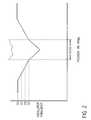
- FIG. 2shows various waveforms and details of operation of the circuit of FIG. 1;
- FIG. 3is a schematic diagram of a second embodiment of a circuit for practicing the invention.
- FIGS. 4A-4Bare schematic diagrams illustrating a comparison of the operation of the first embodiment and the second embodiment
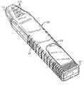
- FIG. 5is a perspective view of an electrical instrument design incorporating the invention
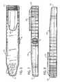
- FIG. 6is top plan view of the instrument of FIG. 5;
- FIG. 7is a right side plan view of the instrument
- FIG. 8is a left side plan view of the instrument
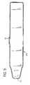
- FIG. 9is a bottom plan view of the instrument.
- FIG. 10is a front plan view of the instrument
- FIG. 11is a rear plan view of the instrument
- FIG. 12is an exploded perspective view illustrating how the sensor plate, circuit board, switch and batteries are assembled in the instrument housing.
- FIG. 13is a schematic showing use of the instrument against a wall to detect a stud.
- FIG. 1there is illustrated a circuit diagram of the invention. Shown on this figure is a portion of a wall structure 10 , studs 11 , 12 and wall board 13 to be illustrative of one way of operating the invention. In this case it is desired to locate the positions of the hidden studs 11 and 12 .
- a metallic sensor plate 21connected to a CMOS oscillator 20 which produces a square (or rectangular) wave output.
- the circuitconsists of a timer IC 22 , the sensor plate and resistors.
- the frequency of the square (or rectangular) wave produced by the oscillator 20is determined by the values of resistors R 1 and R 2 and the capacitance presented by the plate 21 .
- the oscillator 20When the sensor plate is above a section of the wall 13 with no studs it will cause the oscillator 20 to run at frequency f 1 . When the sensor is above a section of the wall 13 that has a stud below it the oscillator will have a different frequency f 2 .
- the square (or rectangular) wave output of the oscillator 20goes to a microprocessor circuit 30 via line 26 .
- the microprocessor circuit 30is programmed to measure the frequency difference f 1 minus f 2 .
- the frequency differencehas been found to be a reliable and consistent means of identifying subsurface objects such as studs and has been found to be relatively independent of the wall material. This makes the device self calibrating, obviating the need for any special factory calibration. If the frequency difference exceeds an amount deemed sufficient to indicate the presence of a stud, an LED is turned on.
- the circuit 30actually has four LEDs D 2 , D 3 , D 4 , D 5 that can be activated at different amounts of frequency change. This is illustrated in more detail in FIG. 2, discussed later on. More or fewer LEDs could be used as indicators depending upon resolution and cost considerations.
- the circuitis powered by batteries 40 (four 1.5 V pancake cells) through protective diode D 1 (e.g., a IN270 diode) and line 42 .
- Resistor R 3is used to limit the current in the LEDs.
- Resistor R 4is used for a power on reset for circuit 30 .
- Normally open switch 45is pressed to enable power to circuit from the batteries 40 to circuit 30 .
- audible indicators D 2 -D 5are described here, it should be clear that audible indicators could be used as well. For example, different audible tones could be produced corresponding to various frequency differences encountered in scanning the wall, as the leading edge of a stud was approached, the frequency could go up, and as the trailing edge of the stud was passed the frequency could go down. In fact, there are occasions where audible indications may be better, such as in cases where the visible indicators may be hard to see.
- FIG. 2there is illustrated the relation of the signal indicator means (LEDs) D 2 -D 5 to the position of the sensor plate along the wall.
- the frequencychanges in accordance with curve 52 .
- the circuit 30(FIG. 1) senses this change and turns on one or more of the LEDs D 2 -D 5 .
- the LEDscould be turned on so as to overlap in on-times or not. In the preferred embodiment, the on-times do not overlap to preserve battery power.
- the plate 21is placed on or in close proximity to wall 13 where there are no studs and the switch 45 is pressed.
- Thiscauses circuit 30 to be activated and it will measure the first frequency f 1 from the oscillator 20 and save it in memory.
- the lowest LED D 3green comes on and stays on as a power indicator, while the switch 45 is pressed.
- Thissignals to the operator that the device can now be moved across the wall being probed.
- the circuit 30is continuously measuring the second or subsequent frequency f 2 from oscillator 20 and comparing it to the first frequency f 1 by taking the frequency difference.
- LED D 4When the difference exceeds a first threshold, the next LED up, LED D 4 (amber) will be lit and LED D 3 will go out.
- LED D 5When the difference exceeds a second threshold, greater than the first threshold, the next LED D 5 (amber) will be turned on and LED D 4 will go out.
- a third thresholdgreater than the second threshold and which indicates the presence of the leading edge of the stud, the highest LED D 2 (red) goes on and the LED D 5 goes out.
- LED D 2stays on as the thickness of the stud is traversed by the device. When the trailing edge of the device is reached, the LEDs go off and on in the reverse sequence.
- the microprocessorcould be programmed to flash the LEDs or beep a buzzer in that event to alert the user to start over, placing the device in a different initial position.
- FIG. 3there is illustrated a circuit diagram of a second embodiment of the invention. Shown on this figure is a portion of a wall structure 60 , studs 61 , 62 and wall board 63 to be illustrative of one way of operating the invention. In this case, it is desired to locate the positions of the hidden studs 61 and 62 .
- a metallic sensor plate 71connected to a CMOS oscillator 70 .
- the frequency of the oscillator 70is determined by IC 72 , the values of resistors R 1 and R 2 and the capacitance presented by the plate 71 .
- the capacitance of the plate 71is determined by the surrounding medium including the wall material, the studs, the circuit and the person holding the device. It is desirable to reduce the stray capacitance as much as possible since this will improve the sensitivity of the plate 71 .
- the capacitance of plate 71is influenced considerably by the operator and the housing of the device.
- Capacitanceis related to its potential with respect to other objects. If an additional plate 75 is introduced in the vicinity of plate 71 with the same potential as plate 71 , it will reduce the “stray” effects. This improves the sensitivity of the plate 71 and allows it to sense further into the wall.
- the potential of plate 71changes as the oscillator 70 operates. In a typical situation it may vary from 0 to 5 volts in amplitude. Hence the guard plate 75 must have its potential vary in the same way. This is accomplished by using a buffer amplifier 78 , with a gain of one, which has the voltage of the sensor plate 71 at its input and produces a near exact replica of it at its output, which is connected to plate 75 via line 77 . Hence plate 75 is driven at the same potential as plate 71 .
- FIG. 4Aa side view of a sensor plate 100 is shown to illustrate how a sensor with a single plate operates.
- the sensor plate 100is connected to the oscillator 103 , which causes its potential to vary.
- the electrical E-field lines 102are free to go in any and all directions.
- FIG. 4Billustrates how the second embodiment described above operates.
- a sensor plate 10is connected to an oscillator 116 and a guard plate 114 is driven from amplifier 118 so it has the same potential as the sensor plate.
- the E-field 112is now prevented from going in the direction of the guard plate 114 . This is because both plates are at the same potential and by electrical laws there can be no E-field between conductors of the same potential. With fewer E-field lines, there is less capacitance of plate 110 . Hence it will be more responsive to dielectric changes in the direction opposite to the guard plate 114 .
- the guard plate 114may be somewhat larger than the sensor plate 10 so as to extend beyond the edges of the sensor plate 110 , which redirects the E-field lines emanating from the edges of the plate 110 in the direction toward the surface being probed.
- the remainder of the circuit of FIG. 3acts in the same way as the first embodiment of FIG. 1 .
- the sensor plateWhen the sensor plate is above a section of the wall 63 with no studs it will cause the oscillator 70 to run at frequency f 1 .
- the oscillatorWhen the sensor is above a section of the wall 63 that has a stud below it the oscillator will have a different frequency 2 .
- the output of the oscillator 70goes to a microprocessor circuit 80 via line 76 .
- the microprocessor circuit 80is programmed to measure the frequency difference f 1 minus f 2 . As in the first embodiment, this can be done by any suitable means.
- the microprocessor circuit 80will typically include a counter. The counter can be programmed to count the number of times the oscillator output signal to the microprocessor goes high in a certain period, which yields a measure of the frequency of the oscillator output. If the frequency difference between the first measured frequency and the subsequently measured frequencies exceeds an amount deemed sufficient to indicate the presence of a stud, an LED is turned on.
- the circuit 80actually has four LEDs D 2 , D 3 , D 4 and D 5 that can be activated at different amounts of frequency change. This is illustrated in more detail in FIG. 2 . More or fewer LEDs could be used as indicators depending upon resolution and cost considerations.
- the circuitis powered by batteries 90 through protective diode D 1 and line 92 .
- Resistor R 3is used to limit the current in the LEDs.
- Resistor R 4is used for a power on reset for circuit 80 .
- Switch 95is pressed to enable power to circuit from the battery 90 to circuit 80 .
- FIGS. 5-13illustrate the design of an electrical instrument, which may include either of the two previously described circuits. As illustrated, this instrument is generally pen-light sized, able to easily fit into a breast pocket. In the preferred embodiment, the device is approximately 1 inch wide, ⁇ fraction (19/32) ⁇ inches thick (not including the pocket clip) and 5 ⁇ fraction (9/16) ⁇ inches long.
- the housing 105is provided with a pocket clip 109 , integrally molded as part of the battery cover 107 , to help hold the device in a user's breast pocket, since the device is small enough to fit, being at least three times longer than it is wide, and in the case of the embodiment disclosed, being over five times longer than it is wide.
- the locatorbe less than two inches wide, which is more than accommodated by the preferred embodiment, since it is only 1 inch wide.
- the instrument in FIGS. 5-13has been labeled with reference numbers as if it includes the first circuit, of FIG. 1 .
- the metal sensor plate 21can be provided on the bottom side of a printed circuit board 101 , and fixed in the housing, for example by an adhesive, so the exposed surface of the plate is against bottom wall 103 of housing 105 so as to minimize any air gap between the plate 21 and the surface being probed.
- the plate 21may be provided as the copper layer commonly provided as part of an ordinary printed circuit board.
- the circuit board 100can be provided with metal (typically copper) layers on both sides, with the layer on side 106 being the guard plate 75 , and the layer 71 being on the lower side, as is layer 21 .
- the lower side sensor platemay be etched so as to make it smaller than the upper side guard plate.
- the other circuitsi.e., the oscillator, microprocessor, LED and buffer amp (if applicable) circuits, are provided on circuit board 115 , which is secured in the housing 105 as far away as possible from the sensor plate 21 .
- the top end of the housing 105tapers in width to a blunt point 111 , to give an operator a better approximation of the center of the device.
- Transparent or translucent windows 113 centered laterally on the front surface of the housing 105are aligned with the respective LEDs D 2 -D 5 and also taper in width toward the top to a sharper point, also to help the operator locate the center of the housing, and therefore the edge of a stud or other subsurface object.
Landscapes
- Life Sciences & Earth Sciences (AREA)
- Physics & Mathematics (AREA)
- Chemical & Material Sciences (AREA)
- General Physics & Mathematics (AREA)
- Geophysics (AREA)
- Electrochemistry (AREA)
- General Life Sciences & Earth Sciences (AREA)
- Geology (AREA)
- Environmental & Geological Engineering (AREA)
- Engineering & Computer Science (AREA)
- Chemical Kinetics & Catalysis (AREA)
- Remote Sensing (AREA)
- Health & Medical Sciences (AREA)
- Analytical Chemistry (AREA)
- Biochemistry (AREA)
- General Health & Medical Sciences (AREA)
- Immunology (AREA)
- Pathology (AREA)
- Geophysics And Detection Of Objects (AREA)
Abstract
Description
Claims (5)
Priority Applications (3)
| Application Number | Priority Date | Filing Date | Title |
|---|---|---|---|
| US09/538,087US6593754B1 (en) | 1999-04-01 | 2000-03-29 | Compact subsurface object locator |
| US09/811,943US6674276B2 (en) | 1999-04-01 | 2001-03-19 | Surface object locator with level indicator and scribe tip |
| US10/457,673US6844713B2 (en) | 1999-04-01 | 2003-06-09 | Compact stud finder |
Applications Claiming Priority (2)
| Application Number | Priority Date | Filing Date | Title |
|---|---|---|---|
| US12732299P | 1999-04-01 | 1999-04-01 | |
| US09/538,087US6593754B1 (en) | 1999-04-01 | 2000-03-29 | Compact subsurface object locator |
Related Child Applications (2)
| Application Number | Title | Priority Date | Filing Date |
|---|---|---|---|
| US09/811,943Continuation-In-PartUS6674276B2 (en) | 1999-04-01 | 2001-03-19 | Surface object locator with level indicator and scribe tip |
| US10/457,673ContinuationUS6844713B2 (en) | 1999-04-01 | 2003-06-09 | Compact stud finder |
Publications (1)
| Publication Number | Publication Date |
|---|---|
| US6593754B1true US6593754B1 (en) | 2003-07-15 |
Family
ID=26825538
Family Applications (2)
| Application Number | Title | Priority Date | Filing Date |
|---|---|---|---|
| US09/538,087Expired - Fee RelatedUS6593754B1 (en) | 1999-04-01 | 2000-03-29 | Compact subsurface object locator |
| US10/457,673Expired - Fee RelatedUS6844713B2 (en) | 1999-04-01 | 2003-06-09 | Compact stud finder |
Family Applications After (1)
| Application Number | Title | Priority Date | Filing Date |
|---|---|---|---|
| US10/457,673Expired - Fee RelatedUS6844713B2 (en) | 1999-04-01 | 2003-06-09 | Compact stud finder |
Country Status (1)
| Country | Link |
|---|---|
| US (2) | US6593754B1 (en) |
Cited By (51)
| Publication number | Priority date | Publication date | Assignee | Title |
|---|---|---|---|---|
| US20050040817A1 (en)* | 2002-02-21 | 2005-02-24 | Stefan Clauss | Method and measuring appliance for locating enclosed objects |
| US20050247460A1 (en)* | 2000-06-20 | 2005-11-10 | Luebke Thomas M | Hand drill attachment |
| US20050280425A1 (en)* | 2004-06-07 | 2005-12-22 | The Stanley Works | Electronic multi-depth object locator with self-illuminating optical element warning and detection |
| US20060037203A1 (en)* | 2004-08-17 | 2006-02-23 | Long Charles K | Modular tool assembly having a vacuum mounting arrangement |
| US7013570B2 (en) | 2003-06-18 | 2006-03-21 | Irwin-Industrial Tool Company | Stud finder |
| US20060185181A1 (en)* | 2004-08-17 | 2006-08-24 | Long Charles K | Structure mountable assembly |
| US7178250B2 (en) | 2004-07-21 | 2007-02-20 | Irwin Industrial Tool Company | Intersecting laser line generating device |
| US20080110038A1 (en)* | 2006-11-14 | 2008-05-15 | Black & Decker Inc. | System and method for hidden object detector with level |
| US20080196910A1 (en)* | 2000-06-20 | 2008-08-21 | Radle Patrick J | Electrical sensing device modules for attachment to power tools and drills |
| US7487596B2 (en) | 2004-06-25 | 2009-02-10 | Irwin Industrial Tool Company | Laser line projected on an edge of a surface |
| US7591075B2 (en) | 2006-09-28 | 2009-09-22 | Techtronic Power Tools Technology Limited | Self-leveling mechanism |
| US8388546B2 (en) | 2006-10-23 | 2013-03-05 | Bard Access Systems, Inc. | Method of locating the tip of a central venous catheter |
| US8388541B2 (en) | 2007-11-26 | 2013-03-05 | C. R. Bard, Inc. | Integrated system for intravascular placement of a catheter |
| US8437833B2 (en) | 2008-10-07 | 2013-05-07 | Bard Access Systems, Inc. | Percutaneous magnetic gastrostomy |
| US8478382B2 (en) | 2008-02-11 | 2013-07-02 | C. R. Bard, Inc. | Systems and methods for positioning a catheter |
| US8512256B2 (en) | 2006-10-23 | 2013-08-20 | Bard Access Systems, Inc. | Method of locating the tip of a central venous catheter |
| CN103513282A (en)* | 2012-06-25 | 2014-01-15 | 罗伯特·博世有限公司 | Hand-held detector |
| USD699359S1 (en) | 2011-08-09 | 2014-02-11 | C. R. Bard, Inc. | Ultrasound probe head |
| US20140145704A1 (en)* | 2010-08-30 | 2014-05-29 | Robert Bosch Gmbh | Method for Localizing Objects Enclosed in a Medium, and Measuring Device for Carrying Out the Method |
| US8781555B2 (en) | 2007-11-26 | 2014-07-15 | C. R. Bard, Inc. | System for placement of a catheter including a signal-generating stylet |
| US8784336B2 (en) | 2005-08-24 | 2014-07-22 | C. R. Bard, Inc. | Stylet apparatuses and methods of manufacture |
| US8801693B2 (en) | 2010-10-29 | 2014-08-12 | C. R. Bard, Inc. | Bioimpedance-assisted placement of a medical device |
| US8849382B2 (en) | 2007-11-26 | 2014-09-30 | C. R. Bard, Inc. | Apparatus and display methods relating to intravascular placement of a catheter |
| USD724745S1 (en) | 2011-08-09 | 2015-03-17 | C. R. Bard, Inc. | Cap for an ultrasound probe |
| US20150177372A1 (en)* | 2013-12-19 | 2015-06-25 | David I. Poisner | MIR Two Dimensional Scanner |
| US9125578B2 (en) | 2009-06-12 | 2015-09-08 | Bard Access Systems, Inc. | Apparatus and method for catheter navigation and tip location |
| US9211107B2 (en) | 2011-11-07 | 2015-12-15 | C. R. Bard, Inc. | Ruggedized ultrasound hydrogel insert |
| US9339206B2 (en) | 2009-06-12 | 2016-05-17 | Bard Access Systems, Inc. | Adaptor for endovascular electrocardiography |
| US9445734B2 (en) | 2009-06-12 | 2016-09-20 | Bard Access Systems, Inc. | Devices and methods for endovascular electrography |
| US9456766B2 (en) | 2007-11-26 | 2016-10-04 | C. R. Bard, Inc. | Apparatus for use with needle insertion guidance system |
| US9492097B2 (en) | 2007-11-26 | 2016-11-15 | C. R. Bard, Inc. | Needle length determination and calibration for insertion guidance system |
| US9521961B2 (en) | 2007-11-26 | 2016-12-20 | C. R. Bard, Inc. | Systems and methods for guiding a medical instrument |
| US9532724B2 (en) | 2009-06-12 | 2017-01-03 | Bard Access Systems, Inc. | Apparatus and method for catheter navigation using endovascular energy mapping |
| US9554716B2 (en) | 2007-11-26 | 2017-01-31 | C. R. Bard, Inc. | Insertion guidance system for needles and medical components |
| US9636031B2 (en) | 2007-11-26 | 2017-05-02 | C.R. Bard, Inc. | Stylets for use with apparatus for intravascular placement of a catheter |
| US9649048B2 (en) | 2007-11-26 | 2017-05-16 | C. R. Bard, Inc. | Systems and methods for breaching a sterile field for intravascular placement of a catheter |
| US9839372B2 (en) | 2014-02-06 | 2017-12-12 | C. R. Bard, Inc. | Systems and methods for guidance and placement of an intravascular device |
| US9901714B2 (en) | 2008-08-22 | 2018-02-27 | C. R. Bard, Inc. | Catheter assembly including ECG sensor and magnetic assemblies |
| US10046139B2 (en) | 2010-08-20 | 2018-08-14 | C. R. Bard, Inc. | Reconfirmation of ECG-assisted catheter tip placement |
| USD836639S1 (en)* | 2015-07-02 | 2018-12-25 | Datalogic Ip Tech S.R.L. | Portable terminal |
| US10349890B2 (en) | 2015-06-26 | 2019-07-16 | C. R. Bard, Inc. | Connector interface for ECG-based catheter positioning system |
| US10449330B2 (en) | 2007-11-26 | 2019-10-22 | C. R. Bard, Inc. | Magnetic element-equipped needle assemblies |
| US10524691B2 (en) | 2007-11-26 | 2020-01-07 | C. R. Bard, Inc. | Needle assembly including an aligned magnetic element |
| US10639008B2 (en) | 2009-10-08 | 2020-05-05 | C. R. Bard, Inc. | Support and cover structures for an ultrasound probe head |
| US10751509B2 (en) | 2007-11-26 | 2020-08-25 | C. R. Bard, Inc. | Iconic representations for guidance of an indwelling medical device |
| US10820885B2 (en) | 2012-06-15 | 2020-11-03 | C. R. Bard, Inc. | Apparatus and methods for detection of a removable cap on an ultrasound probe |
| US10908312B2 (en) | 2016-06-24 | 2021-02-02 | Stanley Black & Decker Inc. | Systems and methods for locating a metal object |
| US10973584B2 (en) | 2015-01-19 | 2021-04-13 | Bard Access Systems, Inc. | Device and method for vascular access |
| US10992079B2 (en) | 2018-10-16 | 2021-04-27 | Bard Access Systems, Inc. | Safety-equipped connection systems and methods thereof for establishing electrical connections |
| US11000207B2 (en) | 2016-01-29 | 2021-05-11 | C. R. Bard, Inc. | Multiple coil system for tracking a medical device |
| US11103213B2 (en) | 2009-10-08 | 2021-08-31 | C. R. Bard, Inc. | Spacers for use with an ultrasound probe |
Families Citing this family (39)
| Publication number | Priority date | Publication date | Assignee | Title |
|---|---|---|---|---|
| DE102004011285A1 (en)* | 2004-03-09 | 2005-09-29 | Robert Bosch Gmbh | tracking device |
| US6978503B2 (en)* | 2004-05-17 | 2005-12-27 | Del Cogliano Kenneth J | Combination stud finder-hammer tool |
| US8253619B2 (en) | 2005-02-15 | 2012-08-28 | Techtronic Power Tools Technology Limited | Electromagnetic scanning imager |
| WO2006088845A2 (en)* | 2005-02-15 | 2006-08-24 | Walleye Technologies, Inc. | Electromagnetic scanning imager |
| US8593157B2 (en)* | 2005-02-15 | 2013-11-26 | Walleye Technologies, Inc. | Electromagnetic scanning imager |
| DE102005015325A1 (en) | 2005-04-01 | 2006-10-05 | Robert Bosch Gmbh | Method for locating objects enclosed in a medium, and measuring device for carrying out the method |
| US8451162B2 (en)* | 2005-12-20 | 2013-05-28 | Walleye Technologies, Inc. | Microwave datum tool |
| CA2676119C (en) | 2007-01-29 | 2021-01-19 | Simon Fraser University | Transvascular nerve stimulation apparatus and methods |
| CA2717860C (en) | 2008-03-07 | 2016-11-08 | Milwaukee Electric Tool Corporation | Battery pack for use with a power tool and a non-motorized sensing tool |
| US9664808B2 (en)* | 2009-03-06 | 2017-05-30 | Milwaukee Electric Tool Corporation | Wall scanner |
| USD623080S1 (en) | 2009-09-04 | 2010-09-07 | Milwaukee Electric Tool Corporation | Wall scanner with pistol-grip handle |
| US8593163B2 (en)* | 2010-03-04 | 2013-11-26 | Franklin Sensors, Inc. | Surface-conforming obscured feature detector |
| US8476912B2 (en)* | 2010-03-04 | 2013-07-02 | Franklin Sensors, Inc. | Obscured feature detector and method |
| US8736283B2 (en)* | 2010-03-04 | 2014-05-27 | Franklin Sensors Inc. | Advanced obscured feature detector |
| US8731333B2 (en)* | 2010-04-06 | 2014-05-20 | Jeffrey M. Sieracki | Inspection of hidden structure |
| US20110311328A1 (en)* | 2010-06-21 | 2011-12-22 | William Alexander Barr | Locating Device for Use with Power Tools |
| US8774911B2 (en)* | 2011-01-04 | 2014-07-08 | Lee M. Buono | Pedicle locator instrument |
| CN103874592B (en) | 2011-08-09 | 2018-01-30 | 大陆汽车系统公司 | Device and method for activating a positioning procedure of a tire pressure monitor |
| US9676238B2 (en) | 2011-08-09 | 2017-06-13 | Continental Automotive Systems, Inc. | Tire pressure monitor system apparatus and method |
| IN2014MN01970A (en) | 2012-03-05 | 2015-07-03 | Univ Fraser Simon | |
| EP2863987B1 (en) | 2012-06-21 | 2023-08-02 | Lungpacer Medical Inc. | Transvascular diaphragm pacing systems |
| CN105873630B (en) | 2013-11-22 | 2020-01-03 | 隆佩瑟尔医疗公司 | Device and method for assisted respiration by transvascular nerve stimulation |
| AU2015208640B2 (en) | 2014-01-21 | 2020-02-20 | Lungpacer Medical Inc. | Systems and related methods for optimization of multi-electrode nerve pacing |
| US9446636B2 (en)* | 2014-02-26 | 2016-09-20 | Continental Automotive Systems, Inc. | Pressure check tool and method of operating the same |
| US9508244B2 (en)* | 2014-03-07 | 2016-11-29 | Zircon Corporation | Sensor with a radiant indicator |
| US9517664B2 (en) | 2015-02-20 | 2016-12-13 | Continental Automotive Systems, Inc. | RF transmission method and apparatus in a tire pressure monitoring system |
| US10261208B2 (en) | 2015-06-23 | 2019-04-16 | David M. Dorrough | Apparatus and methods for detecting obscured features |
| US10613243B2 (en) | 2017-04-27 | 2020-04-07 | Franklin Sensors Inc. | Apparatus and methods for obscured feature detection |
| US10895657B2 (en) | 2017-01-13 | 2021-01-19 | Franklin Sensors Inc. | Apparatus and methods for obscured feature detection with uniform electric fields |
| US10663613B2 (en) | 2015-06-23 | 2020-05-26 | Franklin Sensors, Inc. | Apparatus and methods for detecting obscured features |
| DE102016213290A1 (en) | 2015-08-03 | 2017-02-09 | Continental Automotive Systems, Inc. | Apparatus, system and method for configuring a tire information sensor with a transmission protocol based on vehicle trigger characteristics |
| US10293164B2 (en) | 2017-05-26 | 2019-05-21 | Lungpacer Medical Inc. | Apparatus and methods for assisted breathing by transvascular nerve stimulation |
| CN111163834A (en) | 2017-06-30 | 2020-05-15 | 隆佩瑟尔医疗公司 | Device for preventing, reducing and/or treating cognitive impairment |
| US10195429B1 (en) | 2017-08-02 | 2019-02-05 | Lungpacer Medical Inc. | Systems and methods for intravascular catheter positioning and/or nerve stimulation |
| US10940308B2 (en) | 2017-08-04 | 2021-03-09 | Lungpacer Medical Inc. | Systems and methods for trans-esophageal sympathetic ganglion recruitment |
| US20190175908A1 (en) | 2017-12-11 | 2019-06-13 | Lungpacer Medical Inc. | Systems and methods for strengthening a respiratory muscle |
| EP4548964A1 (en) | 2018-11-08 | 2025-05-07 | Lungpacer Medical Inc. | Stimulation systems and related user interfaces |
| WO2020232333A1 (en) | 2019-05-16 | 2020-11-19 | Lungpacer Medical Inc. | Systems and methods for sensing and stimulation |
| WO2020252037A1 (en) | 2019-06-12 | 2020-12-17 | Lungpacer Medical Inc. | Circuitry for medical stimulation systems |
Citations (21)
| Publication number | Priority date | Publication date | Assignee | Title |
|---|---|---|---|---|
| US3742341A (en)* | 1971-08-16 | 1973-06-26 | Entex Ind Inc | Inductively coupled metal detector arrangement |
| US4099118A (en) | 1977-07-25 | 1978-07-04 | Franklin Robert C | Electronic wall stud sensor |
| US4270041A (en)* | 1977-10-03 | 1981-05-26 | Commissariat A L'energie Atomique | Process and apparatus for detecting the presence of a physical phenomenon |
| US4310797A (en)* | 1978-09-21 | 1982-01-12 | Butler Richard A | Stud detector using a magnetically actuated switch with magnetic biasing |
| US4464622A (en) | 1982-03-11 | 1984-08-07 | Franklin Robert C | Electronic wall stud sensor |
| US4481814A (en)* | 1982-06-28 | 1984-11-13 | Combustion Engineering, Inc. | Stud inspection system |
| US4613816A (en)* | 1984-04-03 | 1986-09-23 | Geo-Sensors Corporation | Cryogenic magnetic probe having new substrate |
| US4853617A (en)* | 1986-03-27 | 1989-08-01 | Keith Douglas | Apparatus having capacitive sensor and metal detector for detecting objects concealed behind surfaces |
| GB2238201A (en)* | 1989-11-17 | 1991-05-22 | British Gas Plc | Ground probing radar |
| US5024236A (en)* | 1988-10-05 | 1991-06-18 | Advanced Medical Technology, Inc. | Photoprobe assembly |
| US5304207A (en)* | 1992-02-05 | 1994-04-19 | Merrill Stromer | Electrostimulator with light emitting device |
| US5352974A (en)* | 1992-08-14 | 1994-10-04 | Zircon Corporation | Stud sensor with digital averager and dual sensitivity |
| US5457394A (en)* | 1993-04-12 | 1995-10-10 | The Regents Of The University Of California | Impulse radar studfinder |
| US5485092A (en) | 1991-08-01 | 1996-01-16 | Fortin; Gabriel | Method and device for electrostatically investigating surface and sub-surface structures |
| US5812057A (en)* | 1994-03-08 | 1998-09-22 | Turner Intellectual Property Ltd. | Device for finding concealed studs |
| US5917314A (en)* | 1996-08-08 | 1999-06-29 | Zircon Corporation | Electronic wall-stud sensor with three capacitive elements |
| USD419546S (en) | 1998-08-13 | 2000-01-25 | Zircon Corporation | Hand held scanning tool |
| US6129668A (en)* | 1997-05-08 | 2000-10-10 | Lucent Medical Systems, Inc. | System and method to determine the location and orientation of an indwelling medical device |
| WO2000079305A1 (en) | 1999-06-22 | 2000-12-28 | Zircon Corporation | Projected display for portable sensor indicating the location of a detected hidden object |
| US6215293B1 (en)* | 1998-08-12 | 2001-04-10 | Solar Wide Industrial Limited | Portable stud detector for detecting wood, metal, and live wires |
| US6229294B1 (en)* | 1998-11-12 | 2001-05-08 | Leon Wun | Magnetic nail/stud sensor |
- 2000
- 2000-03-29USUS09/538,087patent/US6593754B1/ennot_activeExpired - Fee Related
- 2003
- 2003-06-09USUS10/457,673patent/US6844713B2/ennot_activeExpired - Fee Related
Patent Citations (25)
| Publication number | Priority date | Publication date | Assignee | Title |
|---|---|---|---|---|
| US3742341A (en)* | 1971-08-16 | 1973-06-26 | Entex Ind Inc | Inductively coupled metal detector arrangement |
| US4099118A (en) | 1977-07-25 | 1978-07-04 | Franklin Robert C | Electronic wall stud sensor |
| US4270041A (en)* | 1977-10-03 | 1981-05-26 | Commissariat A L'energie Atomique | Process and apparatus for detecting the presence of a physical phenomenon |
| US4310797A (en)* | 1978-09-21 | 1982-01-12 | Butler Richard A | Stud detector using a magnetically actuated switch with magnetic biasing |
| US4464622A (en) | 1982-03-11 | 1984-08-07 | Franklin Robert C | Electronic wall stud sensor |
| US4481814A (en)* | 1982-06-28 | 1984-11-13 | Combustion Engineering, Inc. | Stud inspection system |
| US4613816A (en)* | 1984-04-03 | 1986-09-23 | Geo-Sensors Corporation | Cryogenic magnetic probe having new substrate |
| US4853617A (en)* | 1986-03-27 | 1989-08-01 | Keith Douglas | Apparatus having capacitive sensor and metal detector for detecting objects concealed behind surfaces |
| US4992741A (en)* | 1986-03-27 | 1991-02-12 | The Stanley Works | Capacitive sensor and metal detector with a display for quantitatively displaying signals resulting from concealed objects |
| US5024236A (en)* | 1988-10-05 | 1991-06-18 | Advanced Medical Technology, Inc. | Photoprobe assembly |
| GB2238201A (en)* | 1989-11-17 | 1991-05-22 | British Gas Plc | Ground probing radar |
| US5485092A (en) | 1991-08-01 | 1996-01-16 | Fortin; Gabriel | Method and device for electrostatically investigating surface and sub-surface structures |
| US5304207A (en)* | 1992-02-05 | 1994-04-19 | Merrill Stromer | Electrostimulator with light emitting device |
| US5352974A (en)* | 1992-08-14 | 1994-10-04 | Zircon Corporation | Stud sensor with digital averager and dual sensitivity |
| US5619128A (en)* | 1992-08-14 | 1997-04-08 | Zircon Corporation | Stud sensor with over-stud miscalibration via circuit which stores an initial calibration density, compares that to a current test density and outputs result via indicator |
| US6023159A (en)* | 1992-08-14 | 2000-02-08 | Zircon Corporation | Stud sensor with dual sensitivity |
| US5457394A (en)* | 1993-04-12 | 1995-10-10 | The Regents Of The University Of California | Impulse radar studfinder |
| US5512834A (en)* | 1993-05-07 | 1996-04-30 | The Regents Of The University Of California | Homodyne impulse radar hidden object locator |
| US5812057A (en)* | 1994-03-08 | 1998-09-22 | Turner Intellectual Property Ltd. | Device for finding concealed studs |
| US5917314A (en)* | 1996-08-08 | 1999-06-29 | Zircon Corporation | Electronic wall-stud sensor with three capacitive elements |
| US6129668A (en)* | 1997-05-08 | 2000-10-10 | Lucent Medical Systems, Inc. | System and method to determine the location and orientation of an indwelling medical device |
| US6215293B1 (en)* | 1998-08-12 | 2001-04-10 | Solar Wide Industrial Limited | Portable stud detector for detecting wood, metal, and live wires |
| USD419546S (en) | 1998-08-13 | 2000-01-25 | Zircon Corporation | Hand held scanning tool |
| US6229294B1 (en)* | 1998-11-12 | 2001-05-08 | Leon Wun | Magnetic nail/stud sensor |
| WO2000079305A1 (en) | 1999-06-22 | 2000-12-28 | Zircon Corporation | Projected display for portable sensor indicating the location of a detected hidden object |
Cited By (100)
| Publication number | Priority date | Publication date | Assignee | Title |
|---|---|---|---|---|
| US20050247460A1 (en)* | 2000-06-20 | 2005-11-10 | Luebke Thomas M | Hand drill attachment |
| US20080196910A1 (en)* | 2000-06-20 | 2008-08-21 | Radle Patrick J | Electrical sensing device modules for attachment to power tools and drills |
| US20050040817A1 (en)* | 2002-02-21 | 2005-02-24 | Stefan Clauss | Method and measuring appliance for locating enclosed objects |
| US7358746B2 (en)* | 2002-02-21 | 2008-04-15 | Robert Bosch Gmbh | Method and measuring appliance for locating enclosed objects |
| US7013570B2 (en) | 2003-06-18 | 2006-03-21 | Irwin-Industrial Tool Company | Stud finder |
| US20050280425A1 (en)* | 2004-06-07 | 2005-12-22 | The Stanley Works | Electronic multi-depth object locator with self-illuminating optical element warning and detection |
| US7193405B2 (en) | 2004-06-07 | 2007-03-20 | The Stanley Works | Electronic multi-depth object locator with self-illuminating optical element warning and detection |
| US7487596B2 (en) | 2004-06-25 | 2009-02-10 | Irwin Industrial Tool Company | Laser line projected on an edge of a surface |
| US7310887B2 (en) | 2004-07-21 | 2007-12-25 | Irwin Industrial Tool Company | Intersecting laser line generating device |
| US7469481B2 (en) | 2004-07-21 | 2008-12-30 | Irwin Industrial Tool Company | Intersecting laser line generating device |
| US7178250B2 (en) | 2004-07-21 | 2007-02-20 | Irwin Industrial Tool Company | Intersecting laser line generating device |
| US7322116B2 (en) | 2004-08-17 | 2008-01-29 | Eastway Fair Company Limited | Laser leveling device having a suction mounting arrangement |
| US20070101594A1 (en)* | 2004-08-17 | 2007-05-10 | Eastway Fair Company | Structure mountable assembly |
| US7191532B2 (en) | 2004-08-17 | 2007-03-20 | Eastway Fair Company Limited | Modular tool assembly having a vacuum mounting arrangement |
| US7181854B2 (en) | 2004-08-17 | 2007-02-27 | Eastway Fair Company Limited | Laser leveling device having a suction mounting arrangement |
| US7174648B2 (en) | 2004-08-17 | 2007-02-13 | Eastway Fair Company | Structure mountable assembly |
| US20060185181A1 (en)* | 2004-08-17 | 2006-08-24 | Long Charles K | Structure mountable assembly |
| US7260895B2 (en) | 2004-08-17 | 2007-08-28 | Eastway Fair Company | Structure mountable assembly |
| US20060037203A1 (en)* | 2004-08-17 | 2006-02-23 | Long Charles K | Modular tool assembly having a vacuum mounting arrangement |
| US11207496B2 (en) | 2005-08-24 | 2021-12-28 | C. R. Bard, Inc. | Stylet apparatuses and methods of manufacture |
| US8784336B2 (en) | 2005-08-24 | 2014-07-22 | C. R. Bard, Inc. | Stylet apparatuses and methods of manufacture |
| US10004875B2 (en) | 2005-08-24 | 2018-06-26 | C. R. Bard, Inc. | Stylet apparatuses and methods of manufacture |
| US7591075B2 (en) | 2006-09-28 | 2009-09-22 | Techtronic Power Tools Technology Limited | Self-leveling mechanism |
| US8388546B2 (en) | 2006-10-23 | 2013-03-05 | Bard Access Systems, Inc. | Method of locating the tip of a central venous catheter |
| US8512256B2 (en) | 2006-10-23 | 2013-08-20 | Bard Access Systems, Inc. | Method of locating the tip of a central venous catheter |
| US9833169B2 (en) | 2006-10-23 | 2017-12-05 | Bard Access Systems, Inc. | Method of locating the tip of a central venous catheter |
| US9345422B2 (en) | 2006-10-23 | 2016-05-24 | Bard Acess Systems, Inc. | Method of locating the tip of a central venous catheter |
| US9265443B2 (en) | 2006-10-23 | 2016-02-23 | Bard Access Systems, Inc. | Method of locating the tip of a central venous catheter |
| US8774907B2 (en) | 2006-10-23 | 2014-07-08 | Bard Access Systems, Inc. | Method of locating the tip of a central venous catheter |
| US8858455B2 (en) | 2006-10-23 | 2014-10-14 | Bard Access Systems, Inc. | Method of locating the tip of a central venous catheter |
| US20080110038A1 (en)* | 2006-11-14 | 2008-05-15 | Black & Decker Inc. | System and method for hidden object detector with level |
| US10602958B2 (en) | 2007-11-26 | 2020-03-31 | C. R. Bard, Inc. | Systems and methods for guiding a medical instrument |
| US9521961B2 (en) | 2007-11-26 | 2016-12-20 | C. R. Bard, Inc. | Systems and methods for guiding a medical instrument |
| US8849382B2 (en) | 2007-11-26 | 2014-09-30 | C. R. Bard, Inc. | Apparatus and display methods relating to intravascular placement of a catheter |
| US8781555B2 (en) | 2007-11-26 | 2014-07-15 | C. R. Bard, Inc. | System for placement of a catheter including a signal-generating stylet |
| US10165962B2 (en) | 2007-11-26 | 2019-01-01 | C. R. Bard, Inc. | Integrated systems for intravascular placement of a catheter |
| US11779240B2 (en) | 2007-11-26 | 2023-10-10 | C. R. Bard, Inc. | Systems and methods for breaching a sterile field for intravascular placement of a catheter |
| US11707205B2 (en) | 2007-11-26 | 2023-07-25 | C. R. Bard, Inc. | Integrated system for intravascular placement of a catheter |
| US11529070B2 (en) | 2007-11-26 | 2022-12-20 | C. R. Bard, Inc. | System and methods for guiding a medical instrument |
| US8388541B2 (en) | 2007-11-26 | 2013-03-05 | C. R. Bard, Inc. | Integrated system for intravascular placement of a catheter |
| US11134915B2 (en) | 2007-11-26 | 2021-10-05 | C. R. Bard, Inc. | System for placement of a catheter including a signal-generating stylet |
| US11123099B2 (en) | 2007-11-26 | 2021-09-21 | C. R. Bard, Inc. | Apparatus for use with needle insertion guidance system |
| US10238418B2 (en) | 2007-11-26 | 2019-03-26 | C. R. Bard, Inc. | Apparatus for use with needle insertion guidance system |
| US10966630B2 (en) | 2007-11-26 | 2021-04-06 | C. R. Bard, Inc. | Integrated system for intravascular placement of a catheter |
| US10849695B2 (en) | 2007-11-26 | 2020-12-01 | C. R. Bard, Inc. | Systems and methods for breaching a sterile field for intravascular placement of a catheter |
| US10751509B2 (en) | 2007-11-26 | 2020-08-25 | C. R. Bard, Inc. | Iconic representations for guidance of an indwelling medical device |
| US9456766B2 (en) | 2007-11-26 | 2016-10-04 | C. R. Bard, Inc. | Apparatus for use with needle insertion guidance system |
| US9492097B2 (en) | 2007-11-26 | 2016-11-15 | C. R. Bard, Inc. | Needle length determination and calibration for insertion guidance system |
| US10231753B2 (en) | 2007-11-26 | 2019-03-19 | C. R. Bard, Inc. | Insertion guidance system for needles and medical components |
| US9526440B2 (en) | 2007-11-26 | 2016-12-27 | C.R. Bard, Inc. | System for placement of a catheter including a signal-generating stylet |
| US10105121B2 (en) | 2007-11-26 | 2018-10-23 | C. R. Bard, Inc. | System for placement of a catheter including a signal-generating stylet |
| US9549685B2 (en) | 2007-11-26 | 2017-01-24 | C. R. Bard, Inc. | Apparatus and display methods relating to intravascular placement of a catheter |
| US9554716B2 (en) | 2007-11-26 | 2017-01-31 | C. R. Bard, Inc. | Insertion guidance system for needles and medical components |
| US9636031B2 (en) | 2007-11-26 | 2017-05-02 | C.R. Bard, Inc. | Stylets for use with apparatus for intravascular placement of a catheter |
| US9649048B2 (en) | 2007-11-26 | 2017-05-16 | C. R. Bard, Inc. | Systems and methods for breaching a sterile field for intravascular placement of a catheter |
| US9681823B2 (en) | 2007-11-26 | 2017-06-20 | C. R. Bard, Inc. | Integrated system for intravascular placement of a catheter |
| US10524691B2 (en) | 2007-11-26 | 2020-01-07 | C. R. Bard, Inc. | Needle assembly including an aligned magnetic element |
| US10449330B2 (en) | 2007-11-26 | 2019-10-22 | C. R. Bard, Inc. | Magnetic element-equipped needle assemblies |
| US10342575B2 (en) | 2007-11-26 | 2019-07-09 | C. R. Bard, Inc. | Apparatus for use with needle insertion guidance system |
| US9999371B2 (en) | 2007-11-26 | 2018-06-19 | C. R. Bard, Inc. | Integrated system for intravascular placement of a catheter |
| US8478382B2 (en) | 2008-02-11 | 2013-07-02 | C. R. Bard, Inc. | Systems and methods for positioning a catheter |
| US8971994B2 (en) | 2008-02-11 | 2015-03-03 | C. R. Bard, Inc. | Systems and methods for positioning a catheter |
| US9901714B2 (en) | 2008-08-22 | 2018-02-27 | C. R. Bard, Inc. | Catheter assembly including ECG sensor and magnetic assemblies |
| US11027101B2 (en) | 2008-08-22 | 2021-06-08 | C. R. Bard, Inc. | Catheter assembly including ECG sensor and magnetic assemblies |
| US9907513B2 (en) | 2008-10-07 | 2018-03-06 | Bard Access Systems, Inc. | Percutaneous magnetic gastrostomy |
| US8437833B2 (en) | 2008-10-07 | 2013-05-07 | Bard Access Systems, Inc. | Percutaneous magnetic gastrostomy |
| US10231643B2 (en) | 2009-06-12 | 2019-03-19 | Bard Access Systems, Inc. | Apparatus and method for catheter navigation and tip location |
| US9532724B2 (en) | 2009-06-12 | 2017-01-03 | Bard Access Systems, Inc. | Apparatus and method for catheter navigation using endovascular energy mapping |
| US9339206B2 (en) | 2009-06-12 | 2016-05-17 | Bard Access Systems, Inc. | Adaptor for endovascular electrocardiography |
| US9125578B2 (en) | 2009-06-12 | 2015-09-08 | Bard Access Systems, Inc. | Apparatus and method for catheter navigation and tip location |
| US10271762B2 (en) | 2009-06-12 | 2019-04-30 | Bard Access Systems, Inc. | Apparatus and method for catheter navigation using endovascular energy mapping |
| US9445734B2 (en) | 2009-06-12 | 2016-09-20 | Bard Access Systems, Inc. | Devices and methods for endovascular electrography |
| US11419517B2 (en) | 2009-06-12 | 2022-08-23 | Bard Access Systems, Inc. | Apparatus and method for catheter navigation using endovascular energy mapping |
| US10912488B2 (en) | 2009-06-12 | 2021-02-09 | Bard Access Systems, Inc. | Apparatus and method for catheter navigation and tip location |
| US10639008B2 (en) | 2009-10-08 | 2020-05-05 | C. R. Bard, Inc. | Support and cover structures for an ultrasound probe head |
| US11103213B2 (en) | 2009-10-08 | 2021-08-31 | C. R. Bard, Inc. | Spacers for use with an ultrasound probe |
| US11998386B2 (en) | 2009-10-08 | 2024-06-04 | C. R. Bard, Inc. | Support and cover structures for an ultrasound probe head |
| US10046139B2 (en) | 2010-08-20 | 2018-08-14 | C. R. Bard, Inc. | Reconfirmation of ECG-assisted catheter tip placement |
| US20140145704A1 (en)* | 2010-08-30 | 2014-05-29 | Robert Bosch Gmbh | Method for Localizing Objects Enclosed in a Medium, and Measuring Device for Carrying Out the Method |
| US9415188B2 (en) | 2010-10-29 | 2016-08-16 | C. R. Bard, Inc. | Bioimpedance-assisted placement of a medical device |
| US8801693B2 (en) | 2010-10-29 | 2014-08-12 | C. R. Bard, Inc. | Bioimpedance-assisted placement of a medical device |
| USD699359S1 (en) | 2011-08-09 | 2014-02-11 | C. R. Bard, Inc. | Ultrasound probe head |
| USD724745S1 (en) | 2011-08-09 | 2015-03-17 | C. R. Bard, Inc. | Cap for an ultrasound probe |
| USD754357S1 (en) | 2011-08-09 | 2016-04-19 | C. R. Bard, Inc. | Ultrasound probe head |
| US9211107B2 (en) | 2011-11-07 | 2015-12-15 | C. R. Bard, Inc. | Ruggedized ultrasound hydrogel insert |
| US10820885B2 (en) | 2012-06-15 | 2020-11-03 | C. R. Bard, Inc. | Apparatus and methods for detection of a removable cap on an ultrasound probe |
| CN103513282B (en)* | 2012-06-25 | 2019-01-08 | 罗伯特·博世有限公司 | Hand-held detector |
| CN103513282A (en)* | 2012-06-25 | 2014-01-15 | 罗伯特·博世有限公司 | Hand-held detector |
| US20150177372A1 (en)* | 2013-12-19 | 2015-06-25 | David I. Poisner | MIR Two Dimensional Scanner |
| US9839372B2 (en) | 2014-02-06 | 2017-12-12 | C. R. Bard, Inc. | Systems and methods for guidance and placement of an intravascular device |
| US10863920B2 (en) | 2014-02-06 | 2020-12-15 | C. R. Bard, Inc. | Systems and methods for guidance and placement of an intravascular device |
| US10973584B2 (en) | 2015-01-19 | 2021-04-13 | Bard Access Systems, Inc. | Device and method for vascular access |
| US10349890B2 (en) | 2015-06-26 | 2019-07-16 | C. R. Bard, Inc. | Connector interface for ECG-based catheter positioning system |
| US11026630B2 (en) | 2015-06-26 | 2021-06-08 | C. R. Bard, Inc. | Connector interface for ECG-based catheter positioning system |
| USD836639S1 (en)* | 2015-07-02 | 2018-12-25 | Datalogic Ip Tech S.R.L. | Portable terminal |
| US11000207B2 (en) | 2016-01-29 | 2021-05-11 | C. R. Bard, Inc. | Multiple coil system for tracking a medical device |
| US11067714B2 (en) | 2016-06-24 | 2021-07-20 | Stanley Black & Decker Inc. | Systems and methods for locating a metal object |
| US10908312B2 (en) | 2016-06-24 | 2021-02-02 | Stanley Black & Decker Inc. | Systems and methods for locating a metal object |
| US11621518B2 (en) | 2018-10-16 | 2023-04-04 | Bard Access Systems, Inc. | Safety-equipped connection systems and methods thereof for establishing electrical connections |
| US10992079B2 (en) | 2018-10-16 | 2021-04-27 | Bard Access Systems, Inc. | Safety-equipped connection systems and methods thereof for establishing electrical connections |
Also Published As
| Publication number | Publication date |
|---|---|
| US6844713B2 (en) | 2005-01-18 |
| US20030201783A1 (en) | 2003-10-30 |
Similar Documents
| Publication | Publication Date | Title |
|---|---|---|
| US6593754B1 (en) | Compact subsurface object locator | |
| US6926473B2 (en) | Hand drill attachment | |
| US4992741A (en) | Capacitive sensor and metal detector with a display for quantitatively displaying signals resulting from concealed objects | |
| CA1106932A (en) | Electronic wall stud sensor | |
| US20050247460A1 (en) | Hand drill attachment | |
| US10571423B2 (en) | Systems and methods for locating a stud | |
| US8476912B2 (en) | Obscured feature detector and method | |
| US6188228B1 (en) | Hammer having integral stud and mains sensor | |
| US8593163B2 (en) | Surface-conforming obscured feature detector | |
| US20030015024A1 (en) | Moisture detection apparatus and method | |
| US12265194B2 (en) | Systems and methods for locating a metal object | |
| EP2542921B1 (en) | Obscured feature detector | |
| US10895657B2 (en) | Apparatus and methods for obscured feature detection with uniform electric fields | |
| US20150309203A1 (en) | Electronic drywall fastener locater | |
| US7570041B2 (en) | Magnetic field position sensor and method of use | |
| US20230393183A1 (en) | Apparatus, methods, and techniques of display for obscured feature detection with live wire detection | |
| US11067377B2 (en) | Device and methods for accounting for environmental capacitances caused by an external object when detecting presence and location of surface coatings on transparent and/or translucent medium | |
| EP3671288A1 (en) | Hidden object sensor |
Legal Events
| Date | Code | Title | Description |
|---|---|---|---|
| AS | Assignment | Owner name:CREDIT SUISSE FIRST BOSTON, AS COLLATERAL AGENT, N Free format text:SECURITY AGREEMENT;ASSIGNORS:ACTUANT CORP.;ACTUANT CORPORATION;APPLIED POWER INC.;AND OTHERS;REEL/FRAME:012875/0518 Effective date:20020522 | |
| CC | Certificate of correction | ||
| AS | Assignment | Owner name:ACTUANT CORPORATION, WISCONSIN Free format text:RELEASE OF SECURITY AGREEMENT;ASSIGNOR:CREDIT SUISSE FIRST BOSTON;REEL/FRAME:014515/0923 Effective date:20040219 Owner name:ACTUANT CORPORATION, WISCONSIN Free format text:RELEASE OF SECURITY AGREEMENT;ASSIGNOR:CREDIT SUISSE FIRST BOSTON;REEL/FRAME:014523/0656 Effective date:20040219 Owner name:APW TOOLS AND SUPPLIES, INC. N/K/A GB TOOLS AND SU Free format text:RELEASE OF SECURITY AGREEMENT;ASSIGNOR:CREDIT SUISSE FIRST BOSTON;REEL/FRAME:014523/0656 Effective date:20040219 Owner name:APW TOOLS AND SUPPLIES, INC. N/K/A/ GB TOOLS AND S Free format text:RELEASE OF SECURITY AGREEMENT;ASSIGNOR:CREDIT SUISSE FIRST BOSTON;REEL/FRAME:014515/0923 Effective date:20040219 Owner name:ENGINEERED SOLUTIONS, L.P., WISCONSIN Free format text:RELEASE OF SECURITY AGREEMENT;ASSIGNOR:CREDIT SUISSE FIRST BOSTON;REEL/FRAME:014515/0923 Effective date:20040219 Owner name:ENGINEERED SOLUTIONS, L.P., WISCONSIN Free format text:RELEASE OF SECURITY AGREEMENT;ASSIGNOR:CREDIT SUISSE FIRST BOSTON;REEL/FRAME:014523/0656 Effective date:20040219 Owner name:GB TOOLS AND SUPPLIES, INC., WISCONSIN Free format text:RELEASE OF SECURITY AGREEMENT;ASSIGNOR:CREDIT SUISSE FIRST BOSTON;REEL/FRAME:014515/0923 Effective date:20040219 Owner name:GB TOOLS AND SUPPLIES, INC., WISCONSIN Free format text:RELEASE OF SECURITY AGREEMENT;ASSIGNOR:CREDIT SUISSE FIRST BOSTON;REEL/FRAME:014523/0656 Effective date:20040219 Owner name:VERSA TECHNOLOGIES, INC., WISCONSIN Free format text:RELEASE OF SECURITY AGREEMENT;ASSIGNOR:CREDIT SUISSE FIRST BOSTON;REEL/FRAME:014515/0923 Effective date:20040219 Owner name:VERSA TECHNOLOGIES, INC., WISCONSIN Free format text:RELEASE OF SECURITY AGREEMENT;ASSIGNOR:CREDIT SUISSE FIRST BOSTON;REEL/FRAME:014523/0656 Effective date:20040219 | |
| FPAY | Fee payment | Year of fee payment:4 | |
| REMI | Maintenance fee reminder mailed | ||
| LAPS | Lapse for failure to pay maintenance fees | ||
| STCH | Information on status: patent discontinuation | Free format text:PATENT EXPIRED DUE TO NONPAYMENT OF MAINTENANCE FEES UNDER 37 CFR 1.362 | |
| FP | Lapsed due to failure to pay maintenance fee | Effective date:20110715 |