US6593528B2 - Medical device interface system - Google Patents
Medical device interface systemDownload PDFInfo
- Publication number
- US6593528B2 US6593528B2US10/143,125US14312502AUS6593528B2US 6593528 B2US6593528 B2US 6593528B2US 14312502 AUS14312502 AUS 14312502AUS 6593528 B2US6593528 B2US 6593528B2
- Authority
- US
- United States
- Prior art keywords
- tile
- docking
- rail
- docking station
- casing
- Prior art date
- Legal status (The legal status is an assumption and is not a legal conclusion. Google has not performed a legal analysis and makes no representation as to the accuracy of the status listed.)
- Expired - Fee Related
Links
Images


Classifications
- A—HUMAN NECESSITIES
- A61—MEDICAL OR VETERINARY SCIENCE; HYGIENE
- A61M—DEVICES FOR INTRODUCING MEDIA INTO, OR ONTO, THE BODY; DEVICES FOR TRANSDUCING BODY MEDIA OR FOR TAKING MEDIA FROM THE BODY; DEVICES FOR PRODUCING OR ENDING SLEEP OR STUPOR
- A61M5/00—Devices for bringing media into the body in a subcutaneous, intra-vascular or intramuscular way; Accessories therefor, e.g. filling or cleaning devices, arm-rests
- A61M5/14—Infusion devices, e.g. infusing by gravity; Blood infusion; Accessories therefor
- A61M5/1413—Modular systems comprising interconnecting elements
- F—MECHANICAL ENGINEERING; LIGHTING; HEATING; WEAPONS; BLASTING
- F16—ENGINEERING ELEMENTS AND UNITS; GENERAL MEASURES FOR PRODUCING AND MAINTAINING EFFECTIVE FUNCTIONING OF MACHINES OR INSTALLATIONS; THERMAL INSULATION IN GENERAL
- F16M—FRAMES, CASINGS OR BEDS OF ENGINES, MACHINES OR APPARATUS, NOT SPECIFIC TO ENGINES, MACHINES OR APPARATUS PROVIDED FOR ELSEWHERE; STANDS; SUPPORTS
- F16M11/00—Stands or trestles as supports for apparatus or articles placed thereon ; Stands for scientific apparatus such as gravitational force meters
- F16M11/20—Undercarriages with or without wheels
- F16M11/24—Undercarriages with or without wheels changeable in height or length of legs, also for transport only, e.g. by means of tubes screwed into each other
- F—MECHANICAL ENGINEERING; LIGHTING; HEATING; WEAPONS; BLASTING
- F16—ENGINEERING ELEMENTS AND UNITS; GENERAL MEASURES FOR PRODUCING AND MAINTAINING EFFECTIVE FUNCTIONING OF MACHINES OR INSTALLATIONS; THERMAL INSULATION IN GENERAL
- F16M—FRAMES, CASINGS OR BEDS OF ENGINES, MACHINES OR APPARATUS, NOT SPECIFIC TO ENGINES, MACHINES OR APPARATUS PROVIDED FOR ELSEWHERE; STANDS; SUPPORTS
- F16M13/00—Other supports for positioning apparatus or articles; Means for steadying hand-held apparatus or articles
- F16M13/02—Other supports for positioning apparatus or articles; Means for steadying hand-held apparatus or articles for supporting on, or attaching to, an object, e.g. tree, gate, window-frame, cycle
- H—ELECTRICITY
- H05—ELECTRIC TECHNIQUES NOT OTHERWISE PROVIDED FOR
- H05K—PRINTED CIRCUITS; CASINGS OR CONSTRUCTIONAL DETAILS OF ELECTRIC APPARATUS; MANUFACTURE OF ASSEMBLAGES OF ELECTRICAL COMPONENTS
- H05K5/00—Casings, cabinets or drawers for electric apparatus
- H05K5/30—Side-by-side or stacked arrangements
- H—ELECTRICITY
- H05—ELECTRIC TECHNIQUES NOT OTHERWISE PROVIDED FOR
- H05K—PRINTED CIRCUITS; CASINGS OR CONSTRUCTIONAL DETAILS OF ELECTRIC APPARATUS; MANUFACTURE OF ASSEMBLAGES OF ELECTRICAL COMPONENTS
- H05K7/00—Constructional details common to different types of electric apparatus
- H05K7/14—Mounting supporting structure in casing or on frame or rack
- H05K7/1422—Printed circuit boards receptacles, e.g. stacked structures, electronic circuit modules or box like frames
- H05K7/1435—Expandable constructions
- F—MECHANICAL ENGINEERING; LIGHTING; HEATING; WEAPONS; BLASTING
- F16—ENGINEERING ELEMENTS AND UNITS; GENERAL MEASURES FOR PRODUCING AND MAINTAINING EFFECTIVE FUNCTIONING OF MACHINES OR INSTALLATIONS; THERMAL INSULATION IN GENERAL
- F16M—FRAMES, CASINGS OR BEDS OF ENGINES, MACHINES OR APPARATUS, NOT SPECIFIC TO ENGINES, MACHINES OR APPARATUS PROVIDED FOR ELSEWHERE; STANDS; SUPPORTS
- F16M2200/00—Details of stands or supports
- F16M2200/02—Locking means
- F16M2200/025—Locking means for translational movement
- F16M2200/027—Locking means for translational movement by friction
Definitions
- the inventionrelates generally to a medical device interface system, and more particularly, to an interface for securing a medical device to a mounting device such as a rail or a pole.
- the inventionfurther relates to instrument docking devices providing power and electrical communications between an instrument, associated with the interface, and an external device.
- a mounting deviceis a mounting rail or bar having standard height and depth dimensions.
- such railsare mounted to the walls of a hospital room at various heights and run the entire length of the room.
- the railsare spaced outward from the wall on spacers to allow for the placement of a fastening device between the wall and the back of the rail.
- a typical device for securing a medical device to a mounting railis an L-bracket and a screw clamp.
- the L-bracketis mounted to the back of an instrument near the top and positioned such that when the instrument is mounted to the rail the bracket rests on the top and extends downward behind the back of the rail.
- the screw clampis located on the rear of the instrument and is positioned such that when tightened the screw clamps against the back of the rail.
- This mounting deviceis somewhat inconvenient in that it requires the turning of a clamp screw in space that is typically too small to comfortably accommodate hand movement.
- Pole clampshave commonly been used and have been rigidly mounted to the backs of medical devices. However, unless they are configured to be movable out of the way, they can interfere with other mounting arrangements of the instrument. Such stationary clamps can also cause inconvenience in handling and storage of the instrument due to the protrusion of the clamp. Hence those skilled in the art have recognized a need for a more versatile pole clamp.
- each individual power cord of each individual instrumentis plugged into a power outlet located in the wall or in a power strip extension cord having multiple power outlets.
- Providing power connections in this mannermay be problematic in that cables may become tangled thus rendering the tracing of an individual cable to its associated outlet and the subsequent movement of an individual instrument difficult.
- Safety issuesalso arise in that the use of a power strip extension cord to accommodate multiple instruments may cause a power outlet to be overloaded.
- the more cables that are laying on a hospital floorthe higher the risk of entanglement with a patient or care provider.
- most medical devicesalso require or can accommodate a data communications connection to an external device 'such as a computer. The connection of individual data communications cables to each device further increases the forgoing problems and difficulties.
- the inventionis directed to a device interface system for securing a medical device to a mounting device such as a rail or a pole.
- the inventionis further directed to an instrument docking device for providing power and electrical communications between an instrument, associated with the interface, and an external device.
- the inventionin a first aspect, relates to an interface forming part of an instrument housing for securing the instrument housing to a mounting rail mounted to a surface.
- the interfaceincludes a back panel, a first portion protruding rearward from the back panel and a first recess carried by the protruding portion.
- the first recessis dimensioned to receive the mounting rail.
- the interfacefurther includes a rail cam rotatably mounted within the protruding portion. The rail cam is aligned with the first recess to receive and retain the mounting rail.
- the protruding portionfurther carries a circular cutout partially within the first recess
- the rail camincludes a circular cam base having a surface substantially subflush with the first recess.
- the baseis mounted for pivotal movement within the circular cutout.
- the rail camfurther includes two opposing arms near the periphery of the cam base. The arms extend substantially perpendicular relative the surface of the cam base and each arm has an arm base defining a lock surface. The arms are positioned on the cam base such that the distance between the two lock surfaces is large enough to receive the mounting rail.
- each armfurther includes a guiding portion at the top of the arm base for contacting the mounting rail during insertion of the rail cam onto the mounting rail and transferring the force of contact with the mounting rail to the cam base to therein induce rotation of the rail cam.
- the mounting railhas a height and depth and the guiding portion of each rail-cam arm includes a first portion sloping downward from a first height near the outer periphery of the arm base to a second height inward relative the outer periphery of the arm base. The second height is less than the first height.
- the guiding portionfurther includes a second portion contiguous with the first portion and extending outward from the arm base above the lock surface. The distance between the cam base and the bottom of the second portion is slightly greater than the depth of the mounting rail and the distance between the ends of opposing second portions is less than the height of the mounting rail.
- the first recessincludes a top region defined by at least one substantially planar top surface and an arcuate top surface, the arcuate top surface further defining an arcuate top region.
- the first recessfurther includes a bottom region defined by at least one substantially planar bottom surface and an arcuate bottom surface, the arcuate bottom surface further defining an arcuate bottom region.
- the rail camhas a closed/lock position during which the second portion of one of the arms is positioned above the at least one bottom surface and the second portion of the other arm is positioned below the at least one top surface, and the rail cam has an open/release position during which the second portion of one of the arms is positioned below the at least one bottom surface and the second portion of the other arm is positioned above the at least one top surface.
- the inventionin a second facet, relates to an interface device for securing an instrument to a docking station having a casing having at least one signal port and a mounting rail mounted within a recessed portion of the casing.
- the interface deviceincludes a back panel forming part of an instrument housing for housing the instrument, a first portion protruding rearward from the back panel and a first recess carried by the protruding portion. The first recess is dimensioned to receive the mounting rail.
- the interface devicefurther includes a rail cam rotatably mounted within the protruding portion and aligned with the first recess to receive and retain the mounting rail and at least one first-portion signal port carried by the first portion.
- the first portionis dimensioned to fit within the recessed portion of the casing such that the rail cam is positioned to receive the mounting rail and the at least one first-portion signal port is aligned, in a complementary fashion, with the at least one casing signal port.
- the interface devicefurther includes a pole clamp assembly positioned near the first and second portions.
- the pole clamp assemblyincludes a pivot member moveable between a retracted position and an extended position and a post having an axis.
- the postis mounted to the pivot member for axial movement and mounted thereto such that when the pivot member is retracted the axis of the post is substantially parallel with the back panel and when the pivot member is extended the axis of the post is substantially perpendicular to the back panel.
- the at least one first-portion electrical portincludes a power inlet and the at least one casing electrical port includes a power outlet.
- the casingincludes a relay for controlling the application of power to the power outlet when activated and the first portion comprises a magnet positioned such that when the first portion is within the recessed portion of the casing the magnet activates the relay.
- the at least one first-portion electrical portcomprises a data communications port, the data communications port comprises an IR port and the casing and first-portion comprise a plurality of complementary signal ports.
- the inventionin a third aspect, relates to a rail cam forming part of an instrument housing for securing the instrument housing to a mounting rail having a height and depth and mounted to a surface.
- the rail camincludes a cam base having a surface. The base is mounted for pivotal movement relative the remainder of the instrument housing.
- the rail camfurther includes two opposing arms near the periphery of the cam base. The arms extending substantially perpendicular relative the surface of the cam base, each arm has an arm base defining a lock surface. The arms are positioned on the cam base such that the distance between the two lock surfaces is substantially equal to the height of the mounting rail.
- the rail camfurther includes a guiding portion at the top of each arm base for contacting the mounting rail during insertion of the rail cam onto the mounting rail and transferring the force of contact with the mounting rail to the cam base to therein induce rotation of the rail cam from a closed/lock position to a opened/receive position during which the rail cam receives the mounting rail and subsequently removing the force from the cam base to allow rotation of the rail cam from the open/receive position to the closed/lock position during which the rail cam retains the mounting rail.
- the guiding portionincludes a first portion sloping downward from a first height near the outer periphery of the arm base to a second height inward relative the outer periphery of the arm base.
- the second heightis less than the first height.
- the guiding portionfurther includes a second portion contiguous with the first portion that extends outward from the arm base a distance over the lock surface. The distance between the cam base and the bottom of the second portion is slightly greater than the depth of the mounting rail and the distance between the ends of opposing second portions is less than the height of the mounting rail.
- the rail camfurther includes a lever coupled to the rail cam such that movement of the lever induces rotation of the rail cam between the closed/lock position and an opened/release position during which the mounting rail may be removed from the rail cam, the opened/release position being substantially the same as the opened/receive position.
- the inventionin a fourth facet, relates to a docking station for accepting at least one instrument having a housing having a rail cam and a recess and at least one signal port.
- the docking stationincludes a casing having a plurality of fastening bars recessed a distance from the front of the casing, a docking tile secured to the fastening bars and a rail mounted on the docking tile and spaced a distance therefrom.
- the mounting railis dimensioned to fit within the housing recess and the rail cam.
- the docking stationfurther includes at least one signal port secured to the tile. A portion of the port protrudes forward from the tile and is aligned to couple with the at least one housing signal port when the mounting rail is within the housing recess and rail cam.
- the signal portfurther includes a portion protruding rearward from the tile for interfacing with a signal source.
- the fastening barscomprise channels running the length of the casing and the docking tile may be adjustably positioned along the length of the channels.
- the docking stationfurther includes an electrical circuit mounted to the rear of the docking tile. The electrical circuit provides electrical communication between the at least one tile signal port and an external electrical device.
- a plurality of docking tilesare positioned adjacent each other along the length of the casing. The docking tiles are spaced apart to allow for the mounting of a plurality of instruments having a standard height.
- the docking stationfurther includes spacing plates positioned between adjacent docking tiles to thereby provide a docking station capable of accepting instruments of non-standard height.
- the docking stationfurther comprises a base tile for providing signals to each of the plurality of docking tiles.
- the base tileincludes a power inlet for receiving external power to be provided to each of the plurality of docking tiles and the base tile includes a data communication port for interfacing each of the plurality of docking tiles with an external computer system.
- the inventionin a fifth facet, relates to a docking tile for accepting an instrument having a housing having a rail cam and a recess and at least one electrical port.
- the docking tileincludes a plate, a rail mounted on the plate and spaced a distance therefrom.
- the railis dimensioned to fit within the housing recess and the rail cam.
- the docking tilefurther includes at least one signal port secured to the plate. A portion of the port protrudes forward therefrom and is aligned to couple with the at least one housing signal port when the rail is within the housing recess and the rail cam.
- the portfurther includes a portion protruding rearward therefrom for interfacing with a signal source.
- the docking tilefurther includes an electrical circuit for providing electrical communication between the at least one tile signal port and an external electrical device.
- the at least one tile signal portis a power inlet.
- the electrical circuitincludes a magnetic relay for feeding power to the power outlet when activated.
- the at least one tile electrical portis a data communications port and the data communications port is an IR port.
- the inventionin a sixth facet, relates to a pole clamp assembly forming part of an instrument housing having a back panel with a pole clamp recess.
- the pole clamp assemblyis for securing the instrument housing to a pole and includes a pivot member moveable between a retracted position and an extended position.
- the pole clamp assemblyfurther includes a post having an axis.
- the postis mounted to the pivot member for axial movement and mounted thereto such that when the pivot member is retracted the axis of the post is substantially parallel with the back panel and when the pivot member is extended the axis of the post is substantially perpendicular to the back panel.
- the postis dimensioned and oriented such that when the pivot member is in the retracted position a portion of the post lies within the pole clamp recess.
- the pole clamp recessis defined by a generally arcuate surface and the post includes a threaded stud and a handle having opposing curved sides shaped to substantially match the curved shape of the arcuate surface.
- the handleis positioned at one end of the stud such that when the pivot member is retracted a portion of the handle lies within the pole clamp recess.
- the handlefurther includes opposing rounded edges, wherein upon the application of force to either of the rounded edges the handle is rotated such that one of the curved sides of the handle generally aligns with the arcuate surface defining the pole clamp recess.
- the pole clamp assemblyfurther includes a bracket mounted to the back panel.
- the brackethas a stud recess and the pivot member comprises a generally L-shaped arm having a first leg and a second leg.
- the first legis mounted to the bracket for pivotal movement and the second leg for accepting the stud.
- the second legis positioned relative the first leg to extend into the area near the pole clamp recess such that a portion of the stud lies within the stud recess of the bracket.
- the inventionin a seventh aspect, relates to a device interface for securing an instrument to a docking station having a casing having a mounting rail mounted within an alignment portion of the casing.
- the device interfaceincludes an alignment member forming part of an instrument housing for housing the instrument and a rail cam rotatably mounted to the instrument housing and configured to receive and retain the mounting rail.
- the alignment memberinterfaces with the alignment portion such that the rail cam is positioned to receive the mounting rail.
- the alignment portion of the casingincludes a recess having a width and the alignment member includes at least one portion protruding from the instrument housing having a width slightly less than the width of the recess.
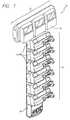
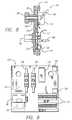
- FIG. 1is an isometric view of a medical interface system in accordance with the invention showing a plurality of medical devices, each of which is secured to a docking station by a medical device interface;
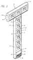
- FIG. 2is an isometric view of the docking station of FIG. 1 with the medical devices removed and having a casing with a plurality of docking tiles recessed therein and a base tile;
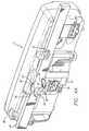
- FIG. 3is an isometric rear view of a medical device having a medical device interface located at the rear of the instrument, the medical device interface having a rail cam assembly, a pole clamp assembly, power connector, IR communications port, and an instrument alignment member;
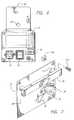
- FIG. 4 ais an isometric view of the medical device of FIG. 3 secured to a mounting rail by the rail cam assembly with portions of the rail cut away for clarity;
- FIG. 4 bis a plan view of the operation of the alignment mounting member at the back of the medical device of FIG. 3 interacting with the alignment recess of the docking station casing to properly and automatically align the power and communications devices of the instrument with those of the docking tile.
- FIG. 5is an isometric view of the medical device of FIG. 3 secured to a pole by the pole clamp assembly;
- FIG. 6is a front view of the base tile of FIG. 2;
- FIG. 7is an isometric view of one of the docking tiles of FIG. 2;
- FIG. 8is a side view of the docking tile of FIG. 7 showing a mounting rail, power connector, signal ports and a circuit card mounted to the back of the tile;
- FIG. 9is a diagram of the circuit card of FIG. 8.
- FIG. 10is an isometric view of a portion of the casing of FIG. 2;
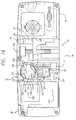
- FIG. 11is a plan view of the casing of FIG. 10;
- FIG. 12depicts an alternate configuration of a docking station showing three docking tiles and a base tile
- FIG. 13depicts another alternate configuration of a docking station showing two vertical casings and an interconnecting horizontal casing located at and engaged with the tops of the vertical casings;
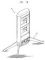
- FIG. 14depicts another alternate configuration of a docking station having a stand
- FIG. 15depicts a docking station having a bag support for holding infusion fluid for use by one or more medical devices that may be mounted to the docking station;
- FIG. 16is a view of the medical device interface of FIG. 3 as viewed from the outside of the medical device with portions of the rail cam cut away for clarity;
- FIG. 17is a view of the medical device interface of FIG. 3 as viewed from the inside of the medical device showing interconnection of the rail cam to an externally located cam control lever, and also showing the spring bias on the rail cam;
- FIGS. 18 a and 18 bare isometric views of the rail cam of FIG. 3;
- FIGS. 18 c through 18 eare a plan view, a front view and a side view, respectively, of the rail cam of FIGS. 18 a and 18 b;
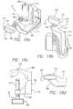
- FIG. 19 ais an isometric view of the pole clamp assembly of FIG. 3 in an opened position
- FIG. 19 bis an isometric view of the pole clamp assembly of FIG. 3 in a closed position
- FIG. 19 cis a top view of the pole clamp assembly of FIG. 19 a.
- FIG. 19 dis a top view of the pole clamp assembly of FIG. 19 b.
- FIGS. 1-3there is shown a medical device interface system 10 (FIG. 1) used with a plurality of individual medical devices 12 , such as syringe infusion pumps 14 and peristaltic infusion pumps 16 .
- Other types of medical devices not shown in FIG. 1may be incorporated into the system.
- Each of the medical devices 12is removably secured to a docking station 18 (FIG. 2) by a medical device interface 48 (FIG. 3) located at the rear of each device.
- the docking station 18includes a plurality of docking tiles 20 and a base tile 22 , each mounted to a casing 24 .
- Each docking tile 20includes a mounting rail 26 mounted to a plate 28 .
- the mounting rail 26has standard height and depth dimensions.
- Also mounted to the plate 28are a power outlet 30 and a data communications port 32 for interfacing with complementary power and data communications components located on the rear of the medical devices 12 (FIG. 3 ).
- the docking tiles 20include a fastener 34 in each corner of the plate 28 for mounting the docking tile to the casing 24 .
- the base tile 22includes a main power inlet 36 and a main on/off switch 38 for connecting each of the docking tiles 20 with an external power source.
- the base tile 22further includes a data communications port 40 for connecting each of the docking tiles 20 with an external data communications device, such as a computer.
- the base tile 22is secured to the casing 24 via front panel fasteners 42 .
- the inside region of the casing 24 and the docking tile plate 28are dimensioned such that the plate fits within the casing.
- a medical device interface (MDI) 48which in this case forms part of a medical device 12 housing is located at the rear of the device.
- the mounting case 50 of the instrumenthas a back panel 76 on which is located the MDI 48 .
- the MDIincludes an instrument alignment mounting member 51 , the purpose of which is to automatically align the other components of the MDI with complementary components of the docking station or of another station.
- the instrument alignment mounting member 51has a first portion 52 and a second portion 54 , each protruding rearward from the back panel.
- the first protruding portion 52includes a first recess 56 while the second protruding portion 54 includes second recess 58 .
- Each recess 56 , 58is dimensioned to receive the mounting rail 26 (FIG. 2) of a docking tile 20 .
- the MDI 48(FIG. 3) further includes a rail cam 60 that is positioned within the first recess 56 and mounted therein for rotation.
- the rail cam 60is biased to a closed/lock position.
- the rail cam 60includes two opposing arms 62 , each having a base 78 and a guiding portion 64 on top of the base.
- Each guiding portion 64has a sloping surface having a portion 80 that extends out over the base 78 of the arm.
- the arm bases 78are spaced apart a distance slightly greater than the height of a mounting rail, such that the mounting rail fits between the arms. The space between the tips of the extension portions 80 is less than the height of the mounting rail.
- the guiding portion 64is sloped to receive the force of a mounting rail 26 during mounting and to induce rotation of the rail cam 60 against its spring bias to an open/receive position during which the mounting rail slips into the space between the arm bases 80 .
- the MDI 48also includes a lever 66 positioned at the top of the mounting case 50 .
- the lever 66rotates the rail cam 60 from its closed/lock position against its spring bias to an open/release position during which the medical device 12 may be removed from the mounting rail 26 .
- the open/release position and the open/receive positionare identical. This position is sometimes referred to as the open/receive/release position.
- the MDI 48further includes a power inlet 68 and a data communication port 70 which are aligned to communicate with complementary power and data communications components located on the docking tiles 20 (FIG. 2 ).
- the pole clamp assembly 72which may be extended for purposes of securing the medical device 12 to a pole.
- the pole clamp assembly 72includes an arm 82 and a threaded post 84 .
- the arm 82is pivotally mounted to the back panel 76 and moves between open and closed positions.
- the post 84is attached to the arm 82 and threadably mounted thereto for movement along the axis of the post.
- the pole clamp assembly 72is positioned relative the first and second portions 52 and 54 such that when the pole clamp assembly is closed the post 84 is positioned in a recess between the two portions.
- the post 84When the pole clamp assembly 72 is opened, the post 84 is substantially perpendicular to the back panel 76 . In this position, the post 84 may be rotated to tighten against a pole placed between the tip of the post and the back panel 76 .
- a medical device 12is secured to a mounting rail 26 by visually aligning the first recess 56 and the second recess 58 with the mounting rail.
- the rail cam 60is pushed against the mounting rail 26 .
- the force of the mounting rail 26 against the guiding portions 64 of the rail cam 60induces rotation of the rail cam such that the mounting rail slides into the space between the arm bases 78 .
- the camreturns to its closed/lock position and the extension portions 80 of the arms 62 hold the device 12 to the rail. If the mounting rail 26 is part of a docking station 18 (FIG. 2 ), the power inlet 68 (FIG.
- the lever 66is activated to cause the rail cam to rotate to its open/release position during which time the extension portions 80 no longer retain the device to the mounting rail 26 .
- a medical device 12is secured to a docking tile 20 by visually aligning the alignment mounting member 51 of the device with the recess formed by the casing 24 . Once aligned, the rail cam 60 is pushed against the mounting rail 26 and secured thereto as just described with reference to FIG. 4 a.
- the medical device 12may be mounted to a pole 74 using the pole clamp assembly 72 .
- the arm 82 of the pole clamp assembly 72is pivoted to its open position.
- the medical device 12is placed on the pole 74 such that the pole lies in the area between the first and second portions 52 , 54 of the MDI 48 .
- the threaded post 84is then rotated until the tip of the post contacts the pole, thereby clamping the instrument 12 to the pole 74 .
- the docking station 18includes a plurality of docking tiles 20 and a base tile 22 , each mounted to a casing 24 .
- the base tile 22is typically positioned near the bottom of the docking station to provide for easy connection with power and data communications cables.
- the docking tiles 20are positioned adjacent each other, one on top of the other or in a side-by-side arrangement.
- the docking tile 20are dimensioned such that when assembled they are spaced apart a distance sufficient to accept a medical device 12 of standard height and/or width dimensions.
- Tile spacersmay be positioned between adjacent docking tiles 20 in order to increase the distance there between to allow for acceptance of non-standard dimensioned medical devices 12 without physical interference between the devices.
- the docking station 18may either be a “dumb” station, i.e., one which provides only power to the medical devices 12 , or a “smart” station, i.e., one which provides both power and data communications to the medical devices.
- the docking station 18includes a vertical casing 44 and a horizontal casing 46 .
- the casings 44 , 46are joined together by a T-piece 47 that fits within the top of the vertical casing 44 and is fastened to the back of the horizontal casing 46 .
- a removable end cap 49At each end of the horizontal casing 46 is .
- the base tile 22includes a main power inlet 36 and an on/off switch 38 for interfacing each of the docking tiles 20 with an external power source. Power is provided to each docking tile 20 in a daisy chain manner through connection provided by adjacent tiles, as described further below.
- the base tile 22includes a connection port through which an earth connection is made with the back of the casing 24 .
- the base tile 22further includes a data communications port 40 for interfacing each of the docking tiles 20 with an external data communications device, such as a computer.
- the base tile 22coordinates data communications with all individual docking tiles 20 located in the docking station.
- Such communicationsmay take the form of a central hospital computer monitoring the status or location, or both, of an individual medical device mounted at the docking station.
- the base tile 22includes Ethernet circuitry for interfacing with an Ethernet system.
- the base tile 22may include the necessary interface for communicating with other devices through an RS-232 bus or other similar bus configurations.
- each docking tile 20includes a standard size mounting rail 26 mounted to a symmetrical shaped plate 28 .
- the plate 28is square, although other shapes are possible, such circular.
- the mounting rail 26has a standard height and depth. In a preferred embodiment, the mounting rail 26 has a height of approximately 25 mm and a depth of approximately 10 mm.
- the mounting rail 26is spaced a distance from the plate 28 by a plurality of spacers 100 .
- the spacers 100are dimensioned to position the mounting rail 26 , relative the plate 28 , such that during mounting, the plate does not contact the back surface of the first and second portions 52 , 54 (FIG. 3 ). The spacers 100 thus ensure that the plate 28 does not inhibit movement of the mounting rail 26 into the first and second recesses 56 , 58 and the rail cam 60 .
- a plurality of signal portse.g., power outlet 30 and a data communications port 32 .
- the power outlet 30is positioned on the plate 28 to align with a complementary power inlet 68 (FIG. 3) located on the rear of a medical device.
- the complementary power componentsinterconnect.
- the data communications port 32is positioned on the plate 28 to align with a complementary data communications component 70 (FIG. 3) located on the rear of a medical device 12 .
- the complementary data communication componentsare infrared (“IR”) ports.
- the communications componentsmay be mechanical in nature, such as pin connectors or telephone connectors.
- a circuit card 102is mounted on the rear of the plate 28 .
- the circuit card 102carries a plurality of circuit components for connecting the signal ports 30 , 32 of individual docking tiles 20 to the corresponding signal ports on the base tile 22 . With regard to power connections, each docking tile 20 receives power through the base tile 22 .
- Power lugs 104 located on the circuit cardreceive power from the base-tile power source via power cables 106 .
- Adjacent docking tiles 20are interconnected in a daisy chain manner through the power cables 106 . This power is provided to the power inlet 30 via relay 110 .
- a cable 108provides an earth connection to the casing 24 (FIG. 2 ).
- the circuit card 102also includes a relay 110 that is activated by a magnet 342 (FIG. 17) positioned within the medical device. When the medical device 12 is mounted on the docking tile 20 , the magnet 342 activates a reed switch 122 which activates the relay 110 to allow for the application of power through the power outlet 30 .
- Activation of the relay 110is indicated by illumination of a red LED 120 located on the circuit board 102 and visible at the front of the docking tile 20 (FIG. 7 ).
- the LED 120illuminates when the relay is activated.
- the relay 110acts as a safety feature by blocking the power signal from the power outlet 30 in the absence of a medical device. Should the relay 110 fail and stick in the activated position, even upon removal of the medical device 12 from the docking tile 20 , the LED 120 indicates the presence of power at the outlet 30 .
- the relay 110is powered by a 12 volt dc signal provided by power connectors 126 . These power connectors 126 receive power from the base tile 22 . The power signal is passed through adjacent docking tiles 20 in a daisy chain manner.
- the circuit card 102further includes data communication connectors 112 . These connectors 112 provide the dc power signal to power the relay 110 . These connectors 112 also communicate with a data cable 114 to provide an interface between the IR port 32 and the main data communications port 40 of the base tile 22 . Adjacent docking tiles 20 are daisy chained together via connectors 112 to provide communication between each docking tile and the communications device connected to the base tile 22 .
- Each docking tile 20is individually mounted to the docking station casing 24 (FIG. 2) by fasteners 34 located in each corner of the plate 28 .
- Each fastener 34includes a screw 116 and a square nut 118 .
- the square nut 118fits within the a square fastener channel located in the casing 24 , as described further below.
- Docking tiles 20may also be mounted directly to a wall or bed instead of being included as part of a docking station 18 .
- power and data communicationsare typically provided directly to the tile, instead of through a base tile 22 .
- Powermay be provided by a wall outlet while data communications may be provided by a data cable such as an RS-323 cable or a telephone line.
- the docking station casing 24includes two sides 200 .
- the casing 24is formed of aluminum. This provides structural rigidity to the casing and electromagnetic capability (EMC) shielding, e.g., electromagnetic interference (EMI) protection, as well as weight reduction.
- EMCelectromagnetic capability
- the casingmay, however, be made of a non-metallic material and EMI screening mounted to the inside to result in the same level of EMI protection as if the casing were made of metal.
- Each side 200is substantially semi-circular in shape and is hollow along its entire length. These hollow sides 200 provide rigidity to the casing 24 while at the same time reducing the weight.
- An arced back panel 202joins the two sides 200 .
- a rear channel bar 206that runs the entire length of the casing 24 .
- a channel plug strip 208Inserted within each of the rear channel bars 206 is a channel plug strip 208 (FIG. 11 ).
- the channel plug strips 208which may be formed of rubber, may be removed and a bracket (not shown) may be installed across the rear of the casing 24 for mounting the casing to a wall or other support medium.
- the center channel bar 210receives the earth cable 108 (FIG. 8) and thereby provides earth bonding. Also on the inside of the casing 24 , near each of the sides 200 is a recess channel bar 212 that runs the entire length of the casing 24 .
- the recess channel bars 212are rectangular in cross section and are sized to receive the square nuts 118 (FIG. 7) associated with the docking-tile fasteners 34 , as previously described.
- the casing 24also includes a pair of threaded channels 222 which receive screws 224 (FIG. 2) for securing the end cap 49 to the casing.
- the distance between the inner walls 214 of the sides 200is selected to be slightly greater than the width of a docking tile plate 28 (FIG. 7) so that the tile can be mounted in the recess 215 formed between the sides 200 .
- the distance between the front of the recess channels 212 and the front 216 of the casing, i.e., the docking station depth,is selected to be slightly greater than the dimension by which the first and second portions 52 , 54 (FIG. 3) of the alignment mounting member 51 of the MDI 48 protrude from the back panel 76 .
- the recess 215 between the sides 200therefore forms an alignment mounting recess that functions to automatically guide the alignment mounting member 51 (FIG.
- the curved configuration of the front 216 part of the casingassists in correctly and automatically aligning the components of the instrument with the components of the docking tile 20 as the interface 48 of the instrument is pressed into the recess 215 .
- This curved configurationtends to direct the interface 48 of the instrument into the recess 215 .
- FIG. 12shows a docking station having three docking tiles 20 and a single base tile 22 mounted within a casing 24 .
- the casing 24is capped at the top and bottom and with such a configuration, the entire assembly is particularly suited to be mounted to a wall by means of a mounting bracket inserted in the rear channel bars 206 of the casing (see FIG. 11 ).
- FIG. 13it is noted that the top horizontal portion of the docking station 18 includes the same casing as the vertical portions.
- docking tiles 20are simply rotated and secured to the casing side-by-side. This is possible due to the square dimensions of the docking tiles plates 28 .
- a docking station 18may be mounted to the wall using brackets attached to the back of the casing.
- a docking station 18may include a stand 218 , as shown in FIG. 14, which allows for placement of the docking station at a location distant from a wall.
- the stand shown in FIG. 14can have wheels mounted at the bottom of each foot so that the stand can accompany a patient who is being moved.
- the medical devices mounted in the docking station 18include battery backup power that allows the devices to continue operation during movement.
- a docking stationmay also include accessories such as a hook apparatus 220 for hanging bags of infusion fluid.
- a clamp assembly 219 in this arrangementis mounted to the end of the horizontal casing 46 instead of an end cap 49 (FIG. 2 ).
- the clamp assembly 219permits control over the height of the hook apparatus 220 .
- a medical device interface (MDI) 48forming part of a medical device housing or attached to the housing is located at the rear of the device.
- the MDIis usually made of plastic.
- the MDI 48includes a rail cam 60 and pole clamp assembly 72 .
- the instrument alignment mounting member 51 forming part of the mounting case 50has a first portion 52 protruding rearward from the case a distance no greater than the depth of a docking station 20 .
- the first portion 52has a height no greater than the height of a docking tile 20 and a width no greater than the width of a docking tile.
- the first recess 56includes a top region 302 and a bottom region 304 .
- the top region 302is defined by two substantially planar top surfaces 306 and an arcuate top surface 308 .
- the portion of the first recess 56 bounded by the arcuate top surface 308defines an arcuate top region 310 .
- the bottom region 304is defined by two substantially planar bottom surfaces 312 and an arcuate bottom surface 314 .
- the portion of the first recess 56 bounded by the arcuate bottom surface 314defines an arcuate bottom region 316 .
- the top and bottom planar surfaces 306 , 312are substantially parallel to each other.
- the first recess 56has a height defined by the distance between the top and bottom planar surfaces 306 , 312 . The height is slightly greater than the height of a mounting rail 26 .
- the first recess 56has a depth defined by the distance between the back surface 318 (FIG. 3) of the recess and the surface 320 of the first portion. The depth is greater than the depth of a mounting rail 26 . Given the height and depth of the first recess 56 , when a mounting rail is placed within the first recess and positioned flush against the back surface 318 of the recess, the mounting rail is recessed relative the surface 320 of the first portion.
- a power inlet 68At the surface 320 of the first portion 52 , in the lower region 322 , is a power inlet 68 , data communications port 70 and a potential equalization connector 324 .
- the power inlet 68 and the data communication port 70are positioned on the surface 320 of the first portion, relative the first recess 56 , such that they align with and interface with the power outlet 30 (FIG. 2) and data communication port 32 of a docking tile when the mounting rail of the docking tile is placed within the first recess.
- a roof 344positioned above the power inlet 68 , serves to prevents fluid from entering the power inlet so that when the medical device 12 is used in a stand alone configuration, i.e., not with a docking station, it reduces the risk of shorting out the electrical power.
- the back surface 318 of the first recess 56includes a circular cutout positioned such that the top and bottom portions of the cutout align with the top and bottom arcuate surfaces 308 , 314 .
- a rail cam 60Positioned within the circular cutout is a rail cam 60 .
- the rail cam 60includes a circular cam base 400 that fits within the circular cutout such that the surface 402 of the circular cam base is substantially subflush with the back surface 318 of the first recess 56 .
- subflushit is meant that the cam base 402 is positioned a slight distance below the back surface 318 .
- the cam base 400is mounted for pivotal movement within the cutout. Positioned near the periphery of the cam base 400 and projecting substantially perpendicular relative the surface 402 of the cam base are a pair of opposing arms 62 .
- Each arm 62includes an arm base 404 defining a lock surface 406 .
- the arms 62are positioned on the cam base 400 such that the distance between the two opposite lock surfaces 406 is slightly greater than the height of a mounting rail 26 to allow for placement of the mounting rail between the lock surfaces.
- Each arm 62also defines a release surface 412 .
- Each arm 62further includes a guiding portion 64 located at the top of the arm base 404 .
- the guiding portion 64includes a first portion 408 sloping downward from a first height near the outer periphery of the arm base 404 to a second height inward relative the outer periphery of the arm base. The second height is less than the first height.
- the guiding portion 64further includes a second portion 410 that is contiguous with the first portion 408 .
- the second portion 410extends outward from the arm base 404 above the lock surface 406 and acts a lip for retaining a mounting rail 26 .
- the arms 62are dimensioned such that the distance between the surface 402 of the cam base 400 and the bottom of the second portion 410 as best shown in FIG. 18 e is substantially equal to the depth of the mounting rail 26 and the distance between the ends of opposing second portions 410 as best shown in FIG. 18 a, is less than the height of the mounting rail. Accordingly, the mounting rail 26 fits within the rail cam 60 and is retained within the rail cam by the second portions 410 .
- the rail cam 60is oriented within the cutout such that the cam rotates between a closed/lock position and a open/receive/release position.
- the rail camis shown in its closed/lock position.
- the lock surface 410 (FIG. 18 d ) of each arm 62is substantially flush with the top and bottom surfaces 306 , 312 of the first recess, respectively and the second portion 410 of each arm extends into the space between the top and bottom surfaces.
- the release surface 412 of each armis substantially flush with the top and bottom surfaces 306 , 312 of the first recess, respectively and the second portion 410 of each arm 62 is positioned within the top and bottom arcuate region 310 , 316 , respectively and thus is outside the space between top and bottom surfaces.
- the rail cam 60is formed of plastic and is capable of supporting between 20 to 30 pounds (9 to 13.5 kilograms). To support heavier weights the rail cam may be made of metal.
- the MDI 48further includes a lever assembly 326 coupled to the rail cam 60 .
- the lever assembly 326includes an external release lever 66 positioned on the exterior side of the MDI.
- the external release lever 66is coupled to an internal release lever 328 positioned beneath the external release lever on the interior side of the MDI.
- the lever assembly 326further includes a rail cam lever 330 coupled to the rail cam 60 and positioned on the interior side of the MDI.
- the rail cam lever 330is biased in the closed/lock position by a spring 334 .
- the rail cam lever 330 and internal release lever 328are coupled together by a release linkage 332 .
- Rotation of the external release lever 66induces rotation of the internal release lever 332 which in turn displaces the release linkage 332 .
- Displacement of the release linkage 332causes the rail cam lever 330 to rotate against the force of the spring 334 which in turn rotates the rail cam 60 .
- Movement of the lever 66rotates the rail cam 60 from its closed/lock position to its open/receive/release position.
- the mounting case 50has a second portion 54 protruding rearward from the case.
- the second portion 54includes a second recess 58 defined by a substantially planar top surface 336 and a substantially planar bottom surface 338 .
- the second recess 58has a height defined by the distance between the top and bottom planar surfaces 336 , 338 .
- the height of the second recess 58is slightly greater than the height of a mounting rail 26 .
- the second recess 58is aligned with the first recess such that a mounting rail 26 may be positioned within both recesses simultaneously.
- the first portions 52 and second portion 54are spaced apart to allow for placement of a portion of the pole clamp assembly 72 there between.
- a pole clamp recess 340Positioned between the first portion 52 and the second portion 54 is a pole clamp recess 340 .
- the pole clamp recess 340has a generally arcuate surface and is dimensioned and orientated to receive a portion of the pole clamp assembly.
- the pole clamp assembly 72includes a bracket 500 , a pivot member 502 and threaded post 504 .
- the post 504includes a threaded stud 506 and a handle 508 .
- the bracket 500is typically mounted to the back panel 72 (FIG. 3) of the MDI 48 near the first and second portions 52 , 54 .
- the pivot member 502is formed in a general L-shape to include a first leg 510 and a second leg 512 .
- the first leg 510is pivotally mounted to the bracket 500 such that the pivot member 502 is moveable between an open position (FIGS. 19 a and 19 c ) and a closed position (FIGS. 19 b and 19 d ).
- the second leg 512carries a threaded hole for receiving the thread stud 506 and allowing for axial movement of the stud.
- the bracket 500has a generally V-shaped cross section. At the point of the V is a stud recess 514 having a semicircular cross section and an axis 516 associated therewith.
- the second leg 512 of the pivot memberis positioned relative the first leg 510 to extend over the bracket 500 such that when the pole clamp assembly 72 is in the closed position, the axis of the stud is substantially parallel with the axis 516 of the stud recess.
- the axis of the postis substantially perpendicular to the axis 516 of the stud recess.
- the handle 508is positioned at one end of the stud 506 and is formed to include opposing curved sides 518 shaped to substantially match the curved shape of the arcuate surface of the pole clamp 340 (FIG. 3 ).
- the handle 508is further formed to include opposing round ends 520 .
- a portion of the handle 508 and stud 506lie within the pole clamp recess 340 a portion of the stud resting within the stud recess 514 .
- the pole clamp assembly componentsare made of metal and may be made by extrusion or casting.
- a medical device 12is secured to a mounting rail 26 by visually aligning the first recess 56 and the second recess 58 with the mounting rail. Once aligned, the rail cam 60 is pushed against the mounting rail 26 . The force of the mounting rail 26 against the sloped guiding portions 64 of the rail cam 60 induces rotation of the rail cam to its open/receive position. In this position the mounting rail is able to slide into the space between the arm bases 404 comes to rest between the lock surfaces 406 the top and bottom surfaces of the first and second recesses 56 , 58 .
- the camreturns to its closed/lock position and the second portions 410 the arms retain the device 12 to the rail.
- the external release lever 66is activated to cause the rail cam 60 rotate to its open/release position during which the second portions 410 the arms 62 move into the top and bottom arcuate regions 310 , 316 , thereby allowing for removal of the device from the mounting rail 26 .
- the handle 508may be orientated such one of the rounded end 520 is facing the mounting rail. Orientated as such, the handle 508 may initially interfere with the mounting process by contacting the mounting rail 26 as it is entering the recessed portions 56 , 58 . However, because of the rounded configuration of the handle end 520 , it easily translates the force resulting from the contact between the rounded end 520 and the mounting rail 26 into rotational motion of the handle. The rounded end slides along the surface of the mounting rail while rotating the handle 508 thereby orientating the handle such that one of the curved sides 518 of the handle generally aligns with the arcuate surface defining the pole clamp recess 340 (FIG. 3 ).
- the medical device 12may be mounted to a pole 74 using the pole clamp assembly 72 .
- the arm 82 of the pole clamp assembly 72is pivoted to its open position.
- the medical device 12is placed on the pole 74 such that the pole lies within the pole clamp assembly recess 340 (FIG. 16) and the bracket 500 (FIG. 19 a ).
- the threaded post 84is then rotated until the tip of the post contacts the pole, thereby clamping the instrument 12 to the pole 74 .
Landscapes
- Engineering & Computer Science (AREA)
- General Engineering & Computer Science (AREA)
- Health & Medical Sciences (AREA)
- Microelectronics & Electronic Packaging (AREA)
- Mechanical Engineering (AREA)
- Heart & Thoracic Surgery (AREA)
- Anesthesiology (AREA)
- Biomedical Technology (AREA)
- Vascular Medicine (AREA)
- Hematology (AREA)
- Life Sciences & Earth Sciences (AREA)
- Animal Behavior & Ethology (AREA)
- General Health & Medical Sciences (AREA)
- Public Health (AREA)
- Veterinary Medicine (AREA)
- Casings For Electric Apparatus (AREA)
- Accommodation For Nursing Or Treatment Tables (AREA)
Abstract
Description
Claims (22)
Priority Applications (1)
| Application Number | Priority Date | Filing Date | Title |
|---|---|---|---|
| US10/143,125US6593528B2 (en) | 1999-11-19 | 2002-05-10 | Medical device interface system |
Applications Claiming Priority (2)
| Application Number | Priority Date | Filing Date | Title |
|---|---|---|---|
| US09/444,328US6407335B1 (en) | 1999-11-19 | 1999-11-19 | Medical device interface system |
| US10/143,125US6593528B2 (en) | 1999-11-19 | 2002-05-10 | Medical device interface system |
Related Parent Applications (1)
| Application Number | Title | Priority Date | Filing Date |
|---|---|---|---|
| US09/444,328DivisionUS6407335B1 (en) | 1999-11-19 | 1999-11-19 | Medical device interface system |
Publications (2)
| Publication Number | Publication Date |
|---|---|
| US20020134570A1 US20020134570A1 (en) | 2002-09-26 |
| US6593528B2true US6593528B2 (en) | 2003-07-15 |
Family
ID=23764454
Family Applications (2)
| Application Number | Title | Priority Date | Filing Date |
|---|---|---|---|
| US09/444,328Expired - LifetimeUS6407335B1 (en) | 1999-11-19 | 1999-11-19 | Medical device interface system |
| US10/143,125Expired - Fee RelatedUS6593528B2 (en) | 1999-11-19 | 2002-05-10 | Medical device interface system |
Family Applications Before (1)
| Application Number | Title | Priority Date | Filing Date |
|---|---|---|---|
| US09/444,328Expired - LifetimeUS6407335B1 (en) | 1999-11-19 | 1999-11-19 | Medical device interface system |
Country Status (1)
| Country | Link |
|---|---|
| US (2) | US6407335B1 (en) |
Cited By (95)
| Publication number | Priority date | Publication date | Assignee | Title |
|---|---|---|---|---|
| US20030176906A1 (en)* | 2002-03-15 | 2003-09-18 | Medtronic, Inc | Method and apparatus for connecting various implantable medical treatment system component devices |
| US20040150963A1 (en)* | 2003-01-31 | 2004-08-05 | Sonosite, Inc. | System for use with a modular apparatus for diagnostic ultrasound |
| US20040152982A1 (en)* | 2002-03-29 | 2004-08-05 | Sonosite, Inc. | Modular apparatus for diagnostic ultrasound |
| US20050046565A1 (en)* | 2003-08-27 | 2005-03-03 | Hill Bobby D. | Alarm device interface system |
| USD506441S1 (en) | 2004-02-06 | 2005-06-21 | Fiskars Brands, Inc. | Utility connection station |
| US20050176290A1 (en)* | 2004-02-06 | 2005-08-11 | Fiskars Brands, Inc. | Utility connection station |
| US20060138270A1 (en)* | 2004-12-29 | 2006-06-29 | Fiskars Brands, Inc. | Portable cord station |
| USD535867S1 (en) | 2004-12-29 | 2007-01-30 | Koninklijke Philips N.V. | Portable cord station |
| US20070032106A1 (en)* | 2005-08-08 | 2007-02-08 | Fiskars Brands, Inc. | Utility connection station |
| USD546286S1 (en) | 2005-08-08 | 2007-07-10 | Koninklijke Philips Electronics N.V. | Utility connection station |
| US20070159772A1 (en)* | 2006-01-11 | 2007-07-12 | Sidney Morice | IV pole attachable retractable cord power outlet |
| US20070184695A1 (en)* | 2005-11-14 | 2007-08-09 | Stefan Knappe | Console for medical supply |
| US20070230167A1 (en)* | 2006-04-03 | 2007-10-04 | Welch Allyn, Inc. | Power connections and interface for compact illuminator assembly |
| US7319386B2 (en) | 2004-08-02 | 2008-01-15 | Hill-Rom Services, Inc. | Configurable system for alerting caregivers |
| USD566282S1 (en)* | 2005-02-18 | 2008-04-08 | Masimo Corporation | Stand for a portable patient monitor |
| USD570802S1 (en) | 2006-04-04 | 2008-06-10 | Sanford, L.P. | Electronics hub |
| LT5554B (en) | 2008-07-11 | 2009-03-25 | Uab "Viltechmeda" | Medical devices fastening system |
| US7831447B2 (en) | 2001-03-30 | 2010-11-09 | Hill-Rom Services, Inc. | Healthcare computer system |
| US7852208B2 (en) | 2004-08-02 | 2010-12-14 | Hill-Rom Services, Inc. | Wireless bed connectivity |
| US7857222B2 (en) | 2007-08-16 | 2010-12-28 | Hand Held Products, Inc. | Data collection system having EIR terminal interface node |
| US7868740B2 (en) | 2007-08-29 | 2011-01-11 | Hill-Rom Services, Inc. | Association of support surfaces and beds |
| US20110022748A1 (en)* | 2009-07-24 | 2011-01-27 | Welch Allyn, Inc. | Configurable health-care equipment apparatus |
| EP2330524A2 (en) | 2005-05-10 | 2011-06-08 | CareFusion 303, Inc. | Medication safety system featuring a multiplexed RFID interrogator panel |
| US20110138310A1 (en)* | 2009-12-08 | 2011-06-09 | Hand Held Products, Inc. | Remote device management interface |
| US8026821B2 (en) | 2000-05-05 | 2011-09-27 | Hill-Rom Services, Inc. | System for monitoring caregivers and equipment at a patient location |
| US8046625B2 (en) | 2008-02-22 | 2011-10-25 | Hill-Rom Services, Inc. | Distributed fault tolerant architecture for a healthcare communication system |
| US8082160B2 (en) | 2007-10-26 | 2011-12-20 | Hill-Rom Services, Inc. | System and method for collection and communication of data from multiple patient care devices |
| US8079559B1 (en) | 2002-02-28 | 2011-12-20 | Sscor, Inc. | Aspirator bracket |
| US8255045B2 (en)* | 2007-04-03 | 2012-08-28 | Nuvasive, Inc. | Neurophysiologic monitoring system |
| US8272892B2 (en) | 2003-08-21 | 2012-09-25 | Hill-Rom Services, Inc. | Hospital bed having wireless data capability |
| US8333038B2 (en) | 2010-02-11 | 2012-12-18 | Herman Miller, Inc. | Wall mounted assembly |
| US8461968B2 (en) | 2007-08-29 | 2013-06-11 | Hill-Rom Services, Inc. | Mattress for a hospital bed for use in a healthcare facility and management of same |
| US8539123B2 (en) | 2011-10-06 | 2013-09-17 | Honeywell International, Inc. | Device management using a dedicated management interface |
| US20130248242A1 (en)* | 2012-03-26 | 2013-09-26 | Gwen Beldock | Electric Plug System |
| US8621123B2 (en) | 2011-10-06 | 2013-12-31 | Honeywell International Inc. | Device management using virtual interfaces |
| US20140127948A1 (en)* | 2012-11-02 | 2014-05-08 | Gwen Beldock | Electric Plug System |
| US8779924B2 (en) | 2010-02-19 | 2014-07-15 | Hill-Rom Services, Inc. | Nurse call system with additional status board |
| US20140265611A1 (en)* | 2013-03-14 | 2014-09-18 | Carefusion 303, Inc. | Intelligent Inductive Power System For Medical Device and System |
| US20140276426A1 (en)* | 2013-03-14 | 2014-09-18 | Carefusion 303, Inc. | Modular Medical Device System |
| US8932217B2 (en) | 2005-01-13 | 2015-01-13 | Welch Allyn, Inc. | Vital signs monitor |
| US20150041419A1 (en)* | 2012-04-23 | 2015-02-12 | Terumo Kabushiki Kaisha | Medical apparatus rack |
| US20150118896A1 (en)* | 2013-10-29 | 2015-04-30 | American Iv, Inc. | Relocatable power tap for use in a patient care area |
| US9092559B2 (en) | 2011-08-16 | 2015-07-28 | Ethicon Endo-Surgery, Inc. | Drug delivery system with open architectural framework |
| US9178324B2 (en) | 2012-11-02 | 2015-11-03 | Belpower Systems Llc | Electric plug system |
| US9230421B2 (en) | 2000-05-05 | 2016-01-05 | Hill-Rom Services, Inc. | System for monitoring caregivers and equipment |
| US9295778B2 (en) | 2011-12-21 | 2016-03-29 | Deka Products Limited Partnership | Syringe pump |
| US9392953B1 (en)* | 2010-09-17 | 2016-07-19 | Nuvasive, Inc. | Neurophysiologic monitoring |
| US9411934B2 (en) | 2012-05-08 | 2016-08-09 | Hill-Rom Services, Inc. | In-room alarm configuration of nurse call system |
| US9468714B2 (en) | 2013-03-14 | 2016-10-18 | Carefusion 303, Inc. | Memory and identification associated with IV set |
| US9744300B2 (en) | 2011-12-21 | 2017-08-29 | Deka Products Limited Partnership | Syringe pump and related method |
| US9757072B1 (en) | 2013-02-11 | 2017-09-12 | Nuvasive, Inc. | Waveform marker placement algorithm for use in neurophysiologic monitoring |
| US9757067B1 (en) | 2012-11-09 | 2017-09-12 | Nuvasive, Inc. | Systems and methods for performing neurophysiologic monitoring during spine surgery |
| US9789247B2 (en) | 2011-12-21 | 2017-10-17 | Deka Products Limited Partnership | Syringe pump, and related method and system |
| US9830424B2 (en) | 2013-09-18 | 2017-11-28 | Hill-Rom Services, Inc. | Bed/room/patient association systems and methods |
| USD810958S1 (en) | 2016-11-04 | 2018-02-20 | Smiths Medical Asd, Inc. | Rack for medical equipment |
| USD816864S1 (en)* | 2016-12-20 | 2018-05-01 | Smiths Medical Asd, Inc. | Notched pole clamp for medical device |
| US9968739B2 (en) | 2013-03-14 | 2018-05-15 | Carefusion 303, Inc. | Rotary valve for a disposable infusion set |
| US10016554B2 (en) | 2008-07-09 | 2018-07-10 | Baxter International Inc. | Dialysis system including wireless patient data |
| US10061899B2 (en) | 2008-07-09 | 2018-08-28 | Baxter International Inc. | Home therapy machine |
| US10136815B2 (en) | 2012-09-24 | 2018-11-27 | Physio-Control, Inc. | Patient monitoring device with remote alert |
| US10173008B2 (en) | 2002-01-29 | 2019-01-08 | Baxter International Inc. | System and method for communicating with a dialysis machine through a network |
| US10226571B2 (en) | 2013-03-14 | 2019-03-12 | Carefusion 303, Inc. | Pump segment placement |
| USD846756S1 (en) | 2016-12-01 | 2019-04-23 | Smiths Medical Asd, Inc. | Pole clamp for medical device |
| US10347374B2 (en) | 2008-10-13 | 2019-07-09 | Baxter Corporation Englewood | Medication preparation system |
| US10360787B2 (en) | 2016-05-05 | 2019-07-23 | Hill-Rom Services, Inc. | Discriminating patient care communications system |
| US10391241B2 (en) | 2010-01-22 | 2019-08-27 | Deka Products Limited Partnership | Syringe pump having a pressure sensor assembly |
| US10420480B1 (en) | 2014-09-16 | 2019-09-24 | Nuvasive, Inc. | Systems and methods for performing neurophysiologic monitoring |
| USD871610S1 (en) | 2018-04-18 | 2019-12-31 | Smiths Medical Asd, Inc. | Pole clamp for medical device |
| US10646405B2 (en) | 2012-10-26 | 2020-05-12 | Baxter Corporation Englewood | Work station for medical dose preparation system |
| US10675402B2 (en) | 2013-05-07 | 2020-06-09 | Carefusion 303, Inc. | Method for reliable intermodule connection in an infusion system |
| US10722645B2 (en) | 2011-12-21 | 2020-07-28 | Deka Products Limited Partnership | Syringe pump, and related method and system |
| EP1881858B1 (en) | 2005-05-14 | 2020-09-23 | B. Braun Melsungen AG | Device for controlling several infusion pumps |
| US10818387B2 (en) | 2014-12-05 | 2020-10-27 | Baxter Corporation Englewood | Dose preparation data analytics |
| US10971257B2 (en) | 2012-10-26 | 2021-04-06 | Baxter Corporation Englewood | Image acquisition for medical dose preparation system |
| US11013853B2 (en) | 2014-02-07 | 2021-05-25 | Carefusion 303, Inc. | Adjustment of infusion user interface upon docking event |
| US11107574B2 (en) | 2014-09-30 | 2021-08-31 | Baxter Corporation Englewood | Management of medication preparation with formulary management |
| US11217340B2 (en) | 2011-12-21 | 2022-01-04 | Deka Products Limited Partnership | Syringe pump having a pressure sensor assembly |
| US11259737B2 (en) | 2012-11-06 | 2022-03-01 | Nuvasive, Inc. | Systems and methods for performing neurophysiologic monitoring during spine surgery |
| US11324886B2 (en) | 2015-06-12 | 2022-05-10 | Carefusion 303, Inc. | Medical device with automated modality switching |
| US11367533B2 (en) | 2014-06-30 | 2022-06-21 | Baxter Corporation Englewood | Managed medical information exchange |
| US11495334B2 (en) | 2015-06-25 | 2022-11-08 | Gambro Lundia Ab | Medical device system and method having a distributed database |
| US11497579B2 (en) | 2017-04-19 | 2022-11-15 | Smiths Medical Asd, Inc. | Pole clamp assembly for medical devices |
| US11504061B2 (en) | 2017-03-21 | 2022-11-22 | Stryker Corporation | Systems and methods for ambient energy powered physiological parameter monitoring |
| US11516183B2 (en) | 2016-12-21 | 2022-11-29 | Gambro Lundia Ab | Medical device system including information technology infrastructure having secure cluster domain supporting external domain |
| US11575673B2 (en) | 2014-09-30 | 2023-02-07 | Baxter Corporation Englewood | Central user management in a distributed healthcare information management system |
| US11801342B2 (en) | 2017-07-19 | 2023-10-31 | Smiths Medical Asd, Inc. | Housing arrangements for infusion pumps |
| US11877860B2 (en) | 2012-11-06 | 2024-01-23 | Nuvasive, Inc. | Systems and methods for performing neurophysiologic monitoring during spine surgery |
| US11911325B2 (en) | 2019-02-26 | 2024-02-27 | Hill-Rom Services, Inc. | Bed interface for manual location |
| US11948112B2 (en) | 2015-03-03 | 2024-04-02 | Baxter Corporation Engelwood | Pharmacy workflow management with integrated alerts |
| US12098738B2 (en) | 2011-12-21 | 2024-09-24 | Deka Products Limited Partnership | System, method, and apparatus for clamping |
| US12131826B2 (en) | 2011-12-21 | 2024-10-29 | Deka Products Limited Partnership | Syringe pump and related method |
| US12186241B2 (en) | 2021-01-22 | 2025-01-07 | Hill-Rom Services, Inc. | Time-based wireless pairing between a medical device and a wall unit |
| US12251243B2 (en) | 2008-02-22 | 2025-03-18 | Hill-Rom Services, Inc. | Distributed healthcare communication system |
| US12279999B2 (en) | 2021-01-22 | 2025-04-22 | Hill-Rom Services, Inc. | Wireless configuration and authorization of a wall unit that pairs with a medical device |
| US12412644B2 (en) | 2014-10-24 | 2025-09-09 | Baxter Corporation Englewood | Automated exchange of healthcare information for fulfillment of medication doses |
Families Citing this family (46)
| Publication number | Priority date | Publication date | Assignee | Title |
|---|---|---|---|---|
| US6407335B1 (en)* | 1999-11-19 | 2002-06-18 | Alaris Medical Systems, Inc. | Medical device interface system |
| US6985870B2 (en) | 2002-01-11 | 2006-01-10 | Baxter International Inc. | Medication delivery system |
| US6850788B2 (en) | 2002-03-25 | 2005-02-01 | Masimo Corporation | Physiological measurement communications adapter |
| US6969928B2 (en)* | 2002-05-31 | 2005-11-29 | Lsi Logic Corporation | Magnetic proximity interface control |
| EP2408052B1 (en)* | 2006-05-12 | 2016-07-13 | Invivo Corporation | Wireless patient parameter sensors for use in MRI |
| US7868250B2 (en) | 2006-08-01 | 2011-01-11 | Priority Worx, Llc | Power supply and cord management apparatus for electronic devices |
| US8840549B2 (en) | 2006-09-22 | 2014-09-23 | Masimo Corporation | Modular patient monitor |
| US20100308187A1 (en)* | 2009-06-04 | 2010-12-09 | Pi-Fen Lin | Integrated magnetic device and a magnetic board thereof |
| US20110208015A1 (en) | 2009-07-20 | 2011-08-25 | Masimo Corporation | Wireless patient monitoring system |
| US9153112B1 (en) | 2009-12-21 | 2015-10-06 | Masimo Corporation | Modular patient monitor |
| US8979915B2 (en)* | 2010-04-19 | 2015-03-17 | Pulsar Scientific, LLC | Separable system for applying compression and thermal treatment |
| CN101969167B (en)* | 2010-08-27 | 2013-01-23 | 深圳市普博科技有限公司 | Method for installing parameter module into host interface and device using same |
| FR2968536B1 (en)* | 2010-12-13 | 2013-01-11 | Coactive Technologies Inc | CONTROL CONSOLE FOR A MEDICAL DEVICE, THE CONSOLE MAY BE FIXED TO A RAIL |
| CN102266599B (en)* | 2010-12-31 | 2013-07-10 | 北京谊安医疗系统股份有限公司 | Medical infusion pump |
| JP5784918B2 (en)* | 2011-02-08 | 2015-09-24 | テルモ株式会社 | Medical pump system and medical pump mounting rack |
| US20130046197A1 (en)* | 2011-08-16 | 2013-02-21 | Daniel F. Dlugos, Jr. | Docking station for patient bedside monitoring units |
| WO2013056160A2 (en) | 2011-10-13 | 2013-04-18 | Masimo Corporation | Medical monitoring hub |
| US9943269B2 (en) | 2011-10-13 | 2018-04-17 | Masimo Corporation | System for displaying medical monitoring data |
| US10149616B2 (en) | 2012-02-09 | 2018-12-11 | Masimo Corporation | Wireless patient monitoring device |
| US9749232B2 (en) | 2012-09-20 | 2017-08-29 | Masimo Corporation | Intelligent medical network edge router |
| JP6105607B2 (en)* | 2012-09-27 | 2017-03-29 | テルモ株式会社 | Device mounting apparatus and method for controlling device mounting apparatus |
| CN103083755B (en)* | 2013-01-06 | 2015-07-15 | 深圳麦科田生物医疗技术有限公司 | Multi-module clamping combined system |
| CN108814559A (en)* | 2013-03-12 | 2018-11-16 | 光学实验室成像公司 | Data gathering system and data gathering system controller |
| US10832818B2 (en) | 2013-10-11 | 2020-11-10 | Masimo Corporation | Alarm notification system |
| FR3018692B1 (en)* | 2014-03-24 | 2020-01-03 | Lucibel Sa | PORTABLE PHOTOTHERAPY TREATMENT MODULE. |
| CN104548250A (en)* | 2015-01-19 | 2015-04-29 | 深圳市科曼医疗设备有限公司 | Workstation, infusion pump, infusion system and infusion pump extension number distinguishing method |
| JP6554293B2 (en)* | 2015-03-02 | 2019-07-31 | フクダ電子株式会社 | Medical equipment |
| US10582981B2 (en)* | 2016-02-02 | 2020-03-10 | Stryker Corporation | Accessory support and coupling systems for an accessory support |
| US10617302B2 (en) | 2016-07-07 | 2020-04-14 | Masimo Corporation | Wearable pulse oximeter and respiration monitor |
| DE102017000851B4 (en)* | 2017-01-31 | 2020-12-10 | Drägerwerk AG & Co. KGaA | Flexible console system for medical devices |
| US11895256B2 (en) | 2017-10-03 | 2024-02-06 | Hatchmed Corporation | Hall monitor for a health care facility |
| US10601971B2 (en)* | 2017-10-03 | 2020-03-24 | Hatchmed Corporation | Portable electronic device holder with assistance request button and method powering portable electronic device |
| US11627212B2 (en) | 2017-10-03 | 2023-04-11 | Hatchmed Corporation | Clamp to attach electronic device holder to bed rail |
| WO2019204368A1 (en) | 2018-04-19 | 2019-10-24 | Masimo Corporation | Mobile patient alarm display |
| CA3053026A1 (en) | 2018-09-07 | 2020-03-07 | Signalisation D'urgence Rh Inc. | Collapsible warning device and method for emitting a light signal |
| US11272839B2 (en) | 2018-10-12 | 2022-03-15 | Ma Simo Corporation | System for transmission of sensor data using dual communication protocol |
| CN212090408U (en)* | 2019-11-20 | 2020-12-08 | 费森尤斯卡比(南昌)医疗器械有限公司 | Holding device for a fluid infusion pump and fluid infusion device comprising the same |
| CN115551570A (en)* | 2020-05-20 | 2022-12-30 | 费森尤斯维尔公司 | Portable Holder for Infusion Sets |
| US11727768B2 (en) | 2020-08-13 | 2023-08-15 | Hatchmed Corporation | Hall monitor for a health care facility |
| US11944779B2 (en) | 2020-10-19 | 2024-04-02 | Walter L. Smith | Intravenous fluid bag supporting assembly |
| USD979764S1 (en)* | 2021-01-15 | 2023-02-28 | B. Braun Melsungen Ag | Rack for syringe pump and/or infusion pump |
| USD989298S1 (en)* | 2021-02-05 | 2023-06-13 | Baxter International Inc. | Infusion pump rack |
| DE202021103538U1 (en)* | 2021-07-01 | 2021-08-09 | B. Braun Melsungen Aktiengesellschaft | Carrying / holding device with an intelligent cover for medical fluid pumps |
| CN114904087A (en)* | 2022-04-29 | 2022-08-16 | 深圳影迈科技有限公司 | infusion pump |
| US20240316260A1 (en)* | 2023-03-20 | 2024-09-26 | B. Braun Medical Inc. | Cradle for an infusion pump |
| WO2025081145A1 (en)* | 2023-10-13 | 2025-04-17 | Baxter International Inc. | Medical device hub power management system and apparatus |
Citations (19)
| Publication number | Priority date | Publication date | Assignee | Title |
|---|---|---|---|---|
| US3888446A (en) | 1974-04-02 | 1975-06-10 | Valmont Industries | Pole mounting bracket attachment |
| US4674722A (en) | 1985-11-18 | 1987-06-23 | Critikon, Inc. | Medical accessory pole clamp |
| US4700922A (en) | 1984-12-20 | 1987-10-20 | The Kendall Company | Medical equipment mounting apparatus |
| US4895161A (en)* | 1986-09-26 | 1990-01-23 | Marquette Electronics | Transportable data module and display unit for patient monitoring system |
| US4970900A (en)* | 1989-01-31 | 1990-11-20 | Baxter International, Inc. | Pole mount organizer with modular interconnection receptacles |
| US5024225A (en)* | 1989-09-26 | 1991-06-18 | William Fang | Personal health monitor enclosure |
| US5431509A (en)* | 1991-11-25 | 1995-07-11 | Minnesota Mining And Manufacturing Company | Interlocking module system |
| US5566676A (en)* | 1992-12-11 | 1996-10-22 | Siemens Medical Systems, Inc. | Pressure data acquisition device for a patient monitoring system |
| US5575807A (en)* | 1994-06-10 | 1996-11-19 | Zmd Corporation | Medical device power supply with AC disconnect alarm and method of supplying power to a medical device |
| DE19621029C1 (en) | 1996-05-24 | 1997-02-27 | Schindler & Schulenburg Gmbh & | Vice for securing accessories to slide rails on operating-table |
| EP0780134A1 (en) | 1995-12-19 | 1997-06-25 | Becton, Dickinson and Company | A modular system, particularly for biomedical applications, a unit and a communication system for use therein |
| US5685314A (en) | 1992-12-11 | 1997-11-11 | Siemens Medical Systems, Inc. | Auxiliary docking station for a patient monitoring system |
| US5829723A (en)* | 1995-06-28 | 1998-11-03 | Medex, Inc. | Medical device mounting structure |
| US6115242A (en)* | 1997-10-24 | 2000-09-05 | Advanced Micro Devices, Inc. | Chip chassis including a micro-backplane for receiving and connecting a plurality of computer chips |
| US6115250A (en)* | 1998-01-20 | 2000-09-05 | Dell Usa, Lp | Computer and an assembly and method for cooling a computer |
| US6183417B1 (en)* | 1992-12-11 | 2001-02-06 | Siemens Medical Systems, Inc. | Docking station for a patient monitoring system |
| US6191943B1 (en)* | 1998-11-12 | 2001-02-20 | Compaq Computer Corporation | Docking station with thermoelectric heat dissipation system for docked portable computer |
| US6407335B1 (en)* | 1999-11-19 | 2002-06-18 | Alaris Medical Systems, Inc. | Medical device interface system |
| US6434001B1 (en)* | 1997-04-22 | 2002-08-13 | Intel Corporation | Heat exchanger for a portable computing device and docking station |
Family Cites Families (2)
| Publication number | Priority date | Publication date | Assignee | Title |
|---|---|---|---|---|
| US5332184A (en)* | 1993-02-16 | 1994-07-26 | Trek Medical Corporation | Pole clamp assembly and a method of its use |
| US5867372A (en)* | 1997-04-16 | 1999-02-02 | Advanced Optronics Corp. | Frame structure for mounting telecommunications equipment |
- 1999
- 1999-11-19USUS09/444,328patent/US6407335B1/ennot_activeExpired - Lifetime
- 2002
- 2002-05-10USUS10/143,125patent/US6593528B2/ennot_activeExpired - Fee Related
Patent Citations (19)
| Publication number | Priority date | Publication date | Assignee | Title |
|---|---|---|---|---|
| US3888446A (en) | 1974-04-02 | 1975-06-10 | Valmont Industries | Pole mounting bracket attachment |
| US4700922A (en) | 1984-12-20 | 1987-10-20 | The Kendall Company | Medical equipment mounting apparatus |
| US4674722A (en) | 1985-11-18 | 1987-06-23 | Critikon, Inc. | Medical accessory pole clamp |
| US4895161A (en)* | 1986-09-26 | 1990-01-23 | Marquette Electronics | Transportable data module and display unit for patient monitoring system |
| US4970900A (en)* | 1989-01-31 | 1990-11-20 | Baxter International, Inc. | Pole mount organizer with modular interconnection receptacles |
| US5024225A (en)* | 1989-09-26 | 1991-06-18 | William Fang | Personal health monitor enclosure |
| US5431509A (en)* | 1991-11-25 | 1995-07-11 | Minnesota Mining And Manufacturing Company | Interlocking module system |
| US5685314A (en) | 1992-12-11 | 1997-11-11 | Siemens Medical Systems, Inc. | Auxiliary docking station for a patient monitoring system |
| US5566676A (en)* | 1992-12-11 | 1996-10-22 | Siemens Medical Systems, Inc. | Pressure data acquisition device for a patient monitoring system |
| US6183417B1 (en)* | 1992-12-11 | 2001-02-06 | Siemens Medical Systems, Inc. | Docking station for a patient monitoring system |
| US5575807A (en)* | 1994-06-10 | 1996-11-19 | Zmd Corporation | Medical device power supply with AC disconnect alarm and method of supplying power to a medical device |
| US5829723A (en)* | 1995-06-28 | 1998-11-03 | Medex, Inc. | Medical device mounting structure |
| EP0780134A1 (en) | 1995-12-19 | 1997-06-25 | Becton, Dickinson and Company | A modular system, particularly for biomedical applications, a unit and a communication system for use therein |
| DE19621029C1 (en) | 1996-05-24 | 1997-02-27 | Schindler & Schulenburg Gmbh & | Vice for securing accessories to slide rails on operating-table |
| US6434001B1 (en)* | 1997-04-22 | 2002-08-13 | Intel Corporation | Heat exchanger for a portable computing device and docking station |
| US6115242A (en)* | 1997-10-24 | 2000-09-05 | Advanced Micro Devices, Inc. | Chip chassis including a micro-backplane for receiving and connecting a plurality of computer chips |
| US6115250A (en)* | 1998-01-20 | 2000-09-05 | Dell Usa, Lp | Computer and an assembly and method for cooling a computer |
| US6191943B1 (en)* | 1998-11-12 | 2001-02-20 | Compaq Computer Corporation | Docking station with thermoelectric heat dissipation system for docked portable computer |
| US6407335B1 (en)* | 1999-11-19 | 2002-06-18 | Alaris Medical Systems, Inc. | Medical device interface system |
Cited By (214)
| Publication number | Priority date | Publication date | Assignee | Title |
|---|---|---|---|---|
| US9230421B2 (en) | 2000-05-05 | 2016-01-05 | Hill-Rom Services, Inc. | System for monitoring caregivers and equipment |
| US8258965B2 (en) | 2000-05-05 | 2012-09-04 | Hill-Rom Services, Inc. | System for monitoring caregivers and equipment at a patient location |
| US8026821B2 (en) | 2000-05-05 | 2011-09-27 | Hill-Rom Services, Inc. | System for monitoring caregivers and equipment at a patient location |
| US8487774B2 (en) | 2000-05-05 | 2013-07-16 | Hill-Rom Services, Inc. | System for monitoring caregivers and equipment |
| US8766804B2 (en) | 2000-05-05 | 2014-07-01 | Hill-Rom Services, Inc. | System for monitoring caregivers and equipment |
| US9666061B2 (en) | 2000-05-05 | 2017-05-30 | Hill-Rom Services, Inc. | System for monitoring caregivers and equipment |
| US7831447B2 (en) | 2001-03-30 | 2010-11-09 | Hill-Rom Services, Inc. | Healthcare computer system |
| US10556062B2 (en) | 2002-01-29 | 2020-02-11 | Baxter International Inc. | Electronic medication order transfer and processing methods and apparatus |
| US10173008B2 (en) | 2002-01-29 | 2019-01-08 | Baxter International Inc. | System and method for communicating with a dialysis machine through a network |
| US8079559B1 (en) | 2002-02-28 | 2011-12-20 | Sscor, Inc. | Aspirator bracket |
| US20030176906A1 (en)* | 2002-03-15 | 2003-09-18 | Medtronic, Inc | Method and apparatus for connecting various implantable medical treatment system component devices |
| US7010355B2 (en) | 2002-03-15 | 2006-03-07 | Medtronic, Inc. | Method and apparatus for connecting various implantable medical treatment system component devices |
| US7534211B2 (en) | 2002-03-29 | 2009-05-19 | Sonosite, Inc. | Modular apparatus for diagnostic ultrasound |
| US20040152982A1 (en)* | 2002-03-29 | 2004-08-05 | Sonosite, Inc. | Modular apparatus for diagnostic ultrasound |
| US8088071B2 (en) | 2002-03-29 | 2012-01-03 | Sonosite, Inc. | Modular apparatus for diagnostic ultrasound |
| US20040150963A1 (en)* | 2003-01-31 | 2004-08-05 | Sonosite, Inc. | System for use with a modular apparatus for diagnostic ultrasound |
| US7591786B2 (en) | 2003-01-31 | 2009-09-22 | Sonosite, Inc. | Dock for connecting peripheral devices to a modular diagnostic ultrasound apparatus |
| US9925104B2 (en) | 2003-08-21 | 2018-03-27 | Hill-Rom Services, Inc. | Hospital bed and room communication modules |
| US10206837B2 (en) | 2003-08-21 | 2019-02-19 | Hill-Rom Services, Inc. | Hospital bed and room communication modules |
| US8272892B2 (en) | 2003-08-21 | 2012-09-25 | Hill-Rom Services, Inc. | Hospital bed having wireless data capability |
| US9142923B2 (en) | 2003-08-21 | 2015-09-22 | Hill-Rom Services, Inc. | Hospital bed having wireless data and locating capability |
| US9572737B2 (en) | 2003-08-21 | 2017-02-21 | Hill-Rom Services, Inc. | Hospital bed having communication modules |
| US20050046565A1 (en)* | 2003-08-27 | 2005-03-03 | Hill Bobby D. | Alarm device interface system |
| US7026945B2 (en) | 2003-08-27 | 2006-04-11 | Bobby Dwyane Hill | Alarm device interface system |
| US20050233622A1 (en)* | 2004-02-06 | 2005-10-20 | Fiskars Brands, Inc. | Utility connection station |
| US20050176290A1 (en)* | 2004-02-06 | 2005-08-11 | Fiskars Brands, Inc. | Utility connection station |
| USD506441S1 (en) | 2004-02-06 | 2005-06-21 | Fiskars Brands, Inc. | Utility connection station |
| US7001211B2 (en) | 2004-02-06 | 2006-02-21 | Fiskars Brands, Inc. | Utility connection station |
| US7081006B2 (en)* | 2004-02-06 | 2006-07-25 | Fiskars Brands, Inc. | Utility connection station |
| US10098593B2 (en) | 2004-08-02 | 2018-10-16 | Hill-Rom Services, Inc. | Bed alert communication method |
| US10978191B2 (en) | 2004-08-02 | 2021-04-13 | Hill-Rom Services, Inc. | Healthcare communication method having configurable alarm rules |
| US10548475B2 (en) | 2004-08-02 | 2020-02-04 | Hill-Rom Services, Inc. | Method of hospital bed network connectivity |
| US9050031B2 (en) | 2004-08-02 | 2015-06-09 | Hill-Rom Services, Inc. | Healthcare communication system having configurable alarm rules |
| US8536990B2 (en) | 2004-08-02 | 2013-09-17 | Hill-Rom Services, Inc. | Hospital bed with nurse call system interface unit |
| US11508469B2 (en) | 2004-08-02 | 2022-11-22 | Hill-Rom Services, Inc. | Hospital bed having wireless network connectivity |
| US9336672B2 (en) | 2004-08-02 | 2016-05-10 | Hill-Rom Services, Inc. | Healthcare communication system for programming bed alarms |
| US7852208B2 (en) | 2004-08-02 | 2010-12-14 | Hill-Rom Services, Inc. | Wireless bed connectivity |
| US9513899B2 (en) | 2004-08-02 | 2016-12-06 | Hill-Rom Services, Inc. | System wide firmware updates to networked hospital beds |
| US7319386B2 (en) | 2004-08-02 | 2008-01-15 | Hill-Rom Services, Inc. | Configurable system for alerting caregivers |
| US9517034B2 (en) | 2004-08-02 | 2016-12-13 | Hill-Rom Services, Inc. | Healthcare communication system for programming bed alarms |
| US8917166B2 (en) | 2004-08-02 | 2014-12-23 | Hill-Rom Services, Inc. | Hospital bed networking system and method |
| US8866598B2 (en) | 2004-08-02 | 2014-10-21 | Hill-Rom Services, Inc. | Healthcare communication system with whiteboard |
| US7746218B2 (en) | 2004-08-02 | 2010-06-29 | Hill-Rom Services, Inc. | Configurable system for alerting caregivers |
| US8120471B2 (en) | 2004-08-02 | 2012-02-21 | Hill-Rom Services, Inc. | Hospital bed with network interface unit |
| US10278582B2 (en) | 2004-08-02 | 2019-05-07 | Hill-Rom Services, Inc. | Hospital bed having wired and wireless network connectivity |
| US8421606B2 (en) | 2004-08-02 | 2013-04-16 | Hill-Rom Services, Inc. | Wireless bed locating system |
| US9775519B2 (en) | 2004-08-02 | 2017-10-03 | Hill-Rom Services, Inc. | Network connectivity unit for hospital bed |
| US20100079276A1 (en)* | 2004-08-02 | 2010-04-01 | Collins Jr Williams F | Hospital bed with network interface unit |
| US9861321B2 (en) | 2004-08-02 | 2018-01-09 | Hill-Rom Services, Inc. | Bed alarm communication system |
| US8284047B2 (en) | 2004-08-02 | 2012-10-09 | Hill-Rom Services, Inc. | Wireless bed connectivity |
| US10070789B2 (en) | 2004-08-02 | 2018-09-11 | Hill-Rom Services, Inc. | Hospital bed having wired and wireless network connectivity |
| US8604917B2 (en) | 2004-08-02 | 2013-12-10 | Hill-Rom Services, Inc. | Hospital bed having user input to enable and suspend remote monitoring of alert conditions |
| USD535867S1 (en) | 2004-12-29 | 2007-01-30 | Koninklijke Philips N.V. | Portable cord station |
| US20060138270A1 (en)* | 2004-12-29 | 2006-06-29 | Fiskars Brands, Inc. | Portable cord station |
| US10165950B2 (en) | 2005-01-13 | 2019-01-01 | Welch Allyn, Inc. | Vital signs monitor |
| US8932217B2 (en) | 2005-01-13 | 2015-01-13 | Welch Allyn, Inc. | Vital signs monitor |
| USD566282S1 (en)* | 2005-02-18 | 2008-04-08 | Masimo Corporation | Stand for a portable patient monitor |
| EP2330524A2 (en) | 2005-05-10 | 2011-06-08 | CareFusion 303, Inc. | Medication safety system featuring a multiplexed RFID interrogator panel |
| EP1881858B1 (en) | 2005-05-14 | 2020-09-23 | B. Braun Melsungen AG | Device for controlling several infusion pumps |
| US20070032106A1 (en)* | 2005-08-08 | 2007-02-08 | Fiskars Brands, Inc. | Utility connection station |
| USD546286S1 (en) | 2005-08-08 | 2007-07-10 | Koninklijke Philips Electronics N.V. | Utility connection station |
| US7963797B2 (en)* | 2005-11-14 | 2011-06-21 | Ondal Holding Gmbh | Console for medical supply |
| US20070184695A1 (en)* | 2005-11-14 | 2007-08-09 | Stefan Knappe | Console for medical supply |
| US20070159772A1 (en)* | 2006-01-11 | 2007-07-12 | Sidney Morice | IV pole attachable retractable cord power outlet |
| US20070230167A1 (en)* | 2006-04-03 | 2007-10-04 | Welch Allyn, Inc. | Power connections and interface for compact illuminator assembly |
| US7758203B2 (en) | 2006-04-03 | 2010-07-20 | Welch Allyn, Inc. | Power connections and interface for compact illuminator assembly |
| USD570802S1 (en) | 2006-04-04 | 2008-06-10 | Sanford, L.P. | Electronics hub |
| USD576118S1 (en) | 2006-04-04 | 2008-09-02 | Sanford, L.P. | Electronics hub |
| US8255045B2 (en)* | 2007-04-03 | 2012-08-28 | Nuvasive, Inc. | Neurophysiologic monitoring system |
| US9295396B2 (en) | 2007-04-03 | 2016-03-29 | Nuvasive, Inc. | Neurophysiologic monitoring system |
| US8925818B2 (en) | 2007-08-16 | 2015-01-06 | Hand Held Products, Inc. | Data collection system having EIR terminal interface node |
| US9258188B2 (en) | 2007-08-16 | 2016-02-09 | Hand Held Products, Inc. | Data collection system having EIR terminal interface node |
| US9929906B2 (en) | 2007-08-16 | 2018-03-27 | Hand Held Products, Inc. | Data collection system having EIR terminal interface node |
| US8556174B2 (en) | 2007-08-16 | 2013-10-15 | Hand Held Products, Inc. | Data collection system having EIR terminal interface node |
| US8297508B2 (en) | 2007-08-16 | 2012-10-30 | Hand Held Products, Inc. | Data collection system having EIR terminal interface node |
| US9509801B2 (en) | 2007-08-16 | 2016-11-29 | Hand Held Products, Inc. | Data collection system having EIR terminal interface node |
| US7857222B2 (en) | 2007-08-16 | 2010-12-28 | Hand Held Products, Inc. | Data collection system having EIR terminal interface node |
| US8025233B2 (en) | 2007-08-16 | 2011-09-27 | Hand Held Products, Inc. | Data collection system having EIR terminal interface node |
| US8461968B2 (en) | 2007-08-29 | 2013-06-11 | Hill-Rom Services, Inc. | Mattress for a hospital bed for use in a healthcare facility and management of same |
| US8604916B2 (en) | 2007-08-29 | 2013-12-10 | Hill-Rom Services, Inc. | Association of support surfaces and beds |
| US8031057B2 (en) | 2007-08-29 | 2011-10-04 | Hill-Rom Services, Inc. | Association of support surfaces and beds |
| US10886024B2 (en) | 2007-08-29 | 2021-01-05 | Hill-Rom Services, Inc. | Bed having housekeeping request button |
| US12230389B2 (en) | 2007-08-29 | 2025-02-18 | Hill-Rom Services, Inc. | Wireless bed locating system |
| US11574736B2 (en) | 2007-08-29 | 2023-02-07 | Hill-Rom Services, Inc. | Wireless bed and surface locating system |
| US10566088B2 (en) | 2007-08-29 | 2020-02-18 | Hill-Rom Services, Inc. | Wireless bed locating system |
| US7868740B2 (en) | 2007-08-29 | 2011-01-11 | Hill-Rom Services, Inc. | Association of support surfaces and beds |
| US8082160B2 (en) | 2007-10-26 | 2011-12-20 | Hill-Rom Services, Inc. | System and method for collection and communication of data from multiple patient care devices |
| US11031130B2 (en) | 2007-10-26 | 2021-06-08 | Hill-Rom Services, Inc. | Patient support apparatus having data collection and communication capability |
| US9734293B2 (en) | 2007-10-26 | 2017-08-15 | Hill-Rom Services, Inc. | System and method for association of patient care devices to a patient |
| US8756078B2 (en) | 2007-10-26 | 2014-06-17 | Hill-Rom Services, Inc. | System and method for collection and communication of data from multiple patient care devices |
| US8384526B2 (en) | 2008-02-22 | 2013-02-26 | Hill-Rom Services, Inc. | Indicator apparatus for healthcare communication system |
| US8169304B2 (en) | 2008-02-22 | 2012-05-01 | Hill-Rom Services, Inc. | User station for healthcare communication system |
| US8762766B2 (en) | 2008-02-22 | 2014-06-24 | Hill-Rom Services, Inc. | Distributed fault tolerant architecture for a healthcare communication system |
| US9235979B2 (en) | 2008-02-22 | 2016-01-12 | Hill-Rom Services, Inc. | User station for healthcare communication system |
| US12251243B2 (en) | 2008-02-22 | 2025-03-18 | Hill-Rom Services, Inc. | Distributed healthcare communication system |
| US9299242B2 (en) | 2008-02-22 | 2016-03-29 | Hill-Rom Services, Inc. | Distributed healthcare communication system |
| US8598995B2 (en) | 2008-02-22 | 2013-12-03 | Hill-Rom Services, Inc. | Distributed healthcare communication system |
| US8456286B2 (en) | 2008-02-22 | 2013-06-04 | Hill-Rom Services, Inc. | User station for healthcare communication system |
| US8392747B2 (en) | 2008-02-22 | 2013-03-05 | Hill-Rom Services, Inc. | Distributed fault tolerant architecture for a healthcare communication system |
| US10307113B2 (en) | 2008-02-22 | 2019-06-04 | Hill-Rom Services, Inc. | Distributed healthcare communication system |
| US10638983B2 (en) | 2008-02-22 | 2020-05-05 | Hill-Rom Services, Inc. | Distributed healthcare communication system |
| US8803669B2 (en) | 2008-02-22 | 2014-08-12 | Hill-Rom Services, Inc. | User station for healthcare communication system |
| US11944467B2 (en) | 2008-02-22 | 2024-04-02 | Hill-Rom Services, Inc. | Distributed healthcare communication system |
| US9955926B2 (en) | 2008-02-22 | 2018-05-01 | Hill-Rom Services, Inc. | Distributed healthcare communication system |
| US11696731B2 (en) | 2008-02-22 | 2023-07-11 | Hill-Room Services, Inc. | Distributed healthcare communication method |
| US11058368B2 (en) | 2008-02-22 | 2021-07-13 | Hill-Rom Services, Inc. | Distributed healthcare communication system |
| US9517035B2 (en) | 2008-02-22 | 2016-12-13 | Hill-Rom Services, Inc. | Distributed healthcare communication system |
| US8046625B2 (en) | 2008-02-22 | 2011-10-25 | Hill-Rom Services, Inc. | Distributed fault tolerant architecture for a healthcare communication system |
| US11918721B2 (en) | 2008-07-09 | 2024-03-05 | Baxter International Inc. | Dialysis system having adaptive prescription management |
| US10068061B2 (en) | 2008-07-09 | 2018-09-04 | Baxter International Inc. | Home therapy entry, modification, and reporting system |
| US10224117B2 (en) | 2008-07-09 | 2019-03-05 | Baxter International Inc. | Home therapy machine allowing patient device program selection |
| US10095840B2 (en) | 2008-07-09 | 2018-10-09 | Baxter International Inc. | System and method for performing renal therapy at a home or dwelling of a patient |
| US11311658B2 (en) | 2008-07-09 | 2022-04-26 | Baxter International Inc. | Dialysis system having adaptive prescription generation |
| US10061899B2 (en) | 2008-07-09 | 2018-08-28 | Baxter International Inc. | Home therapy machine |
| US10646634B2 (en) | 2008-07-09 | 2020-05-12 | Baxter International Inc. | Dialysis system and disposable set |
| US10272190B2 (en) | 2008-07-09 | 2019-04-30 | Baxter International Inc. | Renal therapy system including a blood pressure monitor |
| US10016554B2 (en) | 2008-07-09 | 2018-07-10 | Baxter International Inc. | Dialysis system including wireless patient data |
| LT5554B (en) | 2008-07-11 | 2009-03-25 | Uab "Viltechmeda" | Medical devices fastening system |
| US10347374B2 (en) | 2008-10-13 | 2019-07-09 | Baxter Corporation Englewood | Medication preparation system |
| US8214566B2 (en)* | 2009-07-24 | 2012-07-03 | Welch Allyn, Inc. | Configurable health-care equipment apparatus |
| US8499108B2 (en) | 2009-07-24 | 2013-07-30 | Welch Allyn, Inc. | Configurable health-care equipment apparatus |
| US20110022748A1 (en)* | 2009-07-24 | 2011-01-27 | Welch Allyn, Inc. | Configurable health-care equipment apparatus |
| US9497092B2 (en) | 2009-12-08 | 2016-11-15 | Hand Held Products, Inc. | Remote device management interface |
| US10976891B2 (en) | 2009-12-08 | 2021-04-13 | Hand Held Products, Inc. | Remote device management interface |
| US20110138310A1 (en)* | 2009-12-08 | 2011-06-09 | Hand Held Products, Inc. | Remote device management interface |
| US10391241B2 (en) | 2010-01-22 | 2019-08-27 | Deka Products Limited Partnership | Syringe pump having a pressure sensor assembly |
| US8333038B2 (en) | 2010-02-11 | 2012-12-18 | Herman Miller, Inc. | Wall mounted assembly |
| US9635941B2 (en) | 2010-02-11 | 2017-05-02 | Herman Miller, Inc. | Wall mounted assembly |
| US9072381B2 (en) | 2010-02-11 | 2015-07-07 | Herman Miller, Inc. | Wall mounted assembly |
| US8667742B2 (en) | 2010-02-11 | 2014-03-11 | Herman Miller, Inc. | Wall mounted assembly |
| US8779924B2 (en) | 2010-02-19 | 2014-07-15 | Hill-Rom Services, Inc. | Nurse call system with additional status board |
| US9392953B1 (en)* | 2010-09-17 | 2016-07-19 | Nuvasive, Inc. | Neurophysiologic monitoring |
| US9092559B2 (en) | 2011-08-16 | 2015-07-28 | Ethicon Endo-Surgery, Inc. | Drug delivery system with open architectural framework |
| US9053055B2 (en) | 2011-10-06 | 2015-06-09 | Honeywell International | Device management using virtual interfaces cross-reference to related applications |
| US8539123B2 (en) | 2011-10-06 | 2013-09-17 | Honeywell International, Inc. | Device management using a dedicated management interface |
| US9298667B2 (en) | 2011-10-06 | 2016-03-29 | Honeywell International, Inc | Device management using virtual interfaces cross-reference to related applications |
| US8918564B2 (en) | 2011-10-06 | 2014-12-23 | Honeywell International Inc. | Device management using virtual interfaces |
| US10049075B2 (en) | 2011-10-06 | 2018-08-14 | Honeywell International, Inc. | Device management using virtual interfaces |
| US8621123B2 (en) | 2011-10-06 | 2013-12-31 | Honeywell International Inc. | Device management using virtual interfaces |
| US8868803B2 (en) | 2011-10-06 | 2014-10-21 | Honeywell Internation Inc. | Managing data communication between a peripheral device and a host |
| US12098738B2 (en) | 2011-12-21 | 2024-09-24 | Deka Products Limited Partnership | System, method, and apparatus for clamping |
| US9744300B2 (en) | 2011-12-21 | 2017-08-29 | Deka Products Limited Partnership | Syringe pump and related method |
| US10245374B2 (en) | 2011-12-21 | 2019-04-02 | Deka Products Limited Partnership | Syringe pump |
| US11129933B2 (en) | 2011-12-21 | 2021-09-28 | Deka Products Limited Partnership | Syringe pump, and related method and system |
| US9295778B2 (en) | 2011-12-21 | 2016-03-29 | Deka Products Limited Partnership | Syringe pump |
| US11217340B2 (en) | 2011-12-21 | 2022-01-04 | Deka Products Limited Partnership | Syringe pump having a pressure sensor assembly |
| US10722645B2 (en) | 2011-12-21 | 2020-07-28 | Deka Products Limited Partnership | Syringe pump, and related method and system |
| US11664106B2 (en) | 2011-12-21 | 2023-05-30 | Deka Products Limited Partnership | Syringe pump |
| US11615886B2 (en) | 2011-12-21 | 2023-03-28 | Deka Products Limited Partnership | Syringe pump and related method |
| US12080400B2 (en) | 2011-12-21 | 2024-09-03 | Deka Products Limited Partnership | Syringe pump having a pressure sensor assembly |
| US9789247B2 (en) | 2011-12-21 | 2017-10-17 | Deka Products Limited Partnership | Syringe pump, and related method and system |
| US12131826B2 (en) | 2011-12-21 | 2024-10-29 | Deka Products Limited Partnership | Syringe pump and related method |
| US12431231B2 (en) | 2011-12-21 | 2025-09-30 | DEKA Products Limited Parternship | Syringe pump |
| US11826543B2 (en) | 2011-12-21 | 2023-11-28 | Deka Products Limited Partneship | Syringe pump, and related method and system |
| US10561787B2 (en) | 2011-12-21 | 2020-02-18 | Deka Products Limited Partnership | Syringe pump and related method |
| US20130248242A1 (en)* | 2012-03-26 | 2013-09-26 | Gwen Beldock | Electric Plug System |
| US8723055B2 (en)* | 2012-03-26 | 2014-05-13 | Gwen Beldock | Electric plug system |
| US9808316B2 (en)* | 2012-04-23 | 2017-11-07 | Terumo Kabushiki Kaisha | Medical apparatus rack |
| US20150041419A1 (en)* | 2012-04-23 | 2015-02-12 | Terumo Kabushiki Kaisha | Medical apparatus rack |
| US9411934B2 (en) | 2012-05-08 | 2016-08-09 | Hill-Rom Services, Inc. | In-room alarm configuration of nurse call system |
| US10089443B2 (en) | 2012-05-15 | 2018-10-02 | Baxter International Inc. | Home medical device systems and methods for therapy prescription and tracking, servicing and inventory |
| US12064207B2 (en) | 2012-09-24 | 2024-08-20 | Physio-Control, Inc. | Patient monitoring device with remote alert |
| US11457808B2 (en) | 2012-09-24 | 2022-10-04 | Physio-Control, Inc. | Patient monitoring device with remote alert |
| US10136815B2 (en) | 2012-09-24 | 2018-11-27 | Physio-Control, Inc. | Patient monitoring device with remote alert |
| US10646405B2 (en) | 2012-10-26 | 2020-05-12 | Baxter Corporation Englewood | Work station for medical dose preparation system |
| US10971257B2 (en) | 2012-10-26 | 2021-04-06 | Baxter Corporation Englewood | Image acquisition for medical dose preparation system |
| US20140127948A1 (en)* | 2012-11-02 | 2014-05-08 | Gwen Beldock | Electric Plug System |
| US9124044B2 (en)* | 2012-11-02 | 2015-09-01 | Belpower Systems Llc | Electric plug system |
| US9178324B2 (en) | 2012-11-02 | 2015-11-03 | Belpower Systems Llc | Electric plug system |
| US11877860B2 (en) | 2012-11-06 | 2024-01-23 | Nuvasive, Inc. | Systems and methods for performing neurophysiologic monitoring during spine surgery |
| US11259737B2 (en) | 2012-11-06 | 2022-03-01 | Nuvasive, Inc. | Systems and methods for performing neurophysiologic monitoring during spine surgery |
| US9757067B1 (en) | 2012-11-09 | 2017-09-12 | Nuvasive, Inc. | Systems and methods for performing neurophysiologic monitoring during spine surgery |
| US9757072B1 (en) | 2013-02-11 | 2017-09-12 | Nuvasive, Inc. | Waveform marker placement algorithm for use in neurophysiologic monitoring |
| US20140276426A1 (en)* | 2013-03-14 | 2014-09-18 | Carefusion 303, Inc. | Modular Medical Device System |
| US9522224B2 (en)* | 2013-03-14 | 2016-12-20 | Carefusion 303, Inc. | Inductively powered modular medical device system |
| US9968739B2 (en) | 2013-03-14 | 2018-05-15 | Carefusion 303, Inc. | Rotary valve for a disposable infusion set |
| US9468714B2 (en) | 2013-03-14 | 2016-10-18 | Carefusion 303, Inc. | Memory and identification associated with IV set |
| US10226571B2 (en) | 2013-03-14 | 2019-03-12 | Carefusion 303, Inc. | Pump segment placement |
| US20140265611A1 (en)* | 2013-03-14 | 2014-09-18 | Carefusion 303, Inc. | Intelligent Inductive Power System For Medical Device and System |
| US11844924B2 (en) | 2013-05-07 | 2023-12-19 | Carefusion 303, Inc. | Method for reliable intermodule connection in an infusion system |
| US10675402B2 (en) | 2013-05-07 | 2020-06-09 | Carefusion 303, Inc. | Method for reliable intermodule connection in an infusion system |
| US11065380B2 (en) | 2013-05-07 | 2021-07-20 | Carefusion 303, Inc. | Method for reliable intermodule connection in an infusion system |
| US12354731B2 (en) | 2013-09-18 | 2025-07-08 | Hill-Rom Services, Inc. | Bed/room/patient association systems and methods |
| US9830424B2 (en) | 2013-09-18 | 2017-11-28 | Hill-Rom Services, Inc. | Bed/room/patient association systems and methods |
| US11011267B2 (en) | 2013-09-18 | 2021-05-18 | Hill-Rom Services, Inc. | Bed/room/patient association systems and methods |
| US9543692B2 (en)* | 2013-10-29 | 2017-01-10 | American Iv, Inc. | Relocatable power tap for use in a patient care area |
| US20150118896A1 (en)* | 2013-10-29 | 2015-04-30 | American Iv, Inc. | Relocatable power tap for use in a patient care area |
| US12036383B2 (en) | 2014-02-07 | 2024-07-16 | Carefusion 303, Inc. | Adjustment of infusion user interface upon docking event |
| US11013853B2 (en) | 2014-02-07 | 2021-05-25 | Carefusion 303, Inc. | Adjustment of infusion user interface upon docking event |
| US11367533B2 (en) | 2014-06-30 | 2022-06-21 | Baxter Corporation Englewood | Managed medical information exchange |
| US10420480B1 (en) | 2014-09-16 | 2019-09-24 | Nuvasive, Inc. | Systems and methods for performing neurophysiologic monitoring |
| US11471086B2 (en) | 2014-09-16 | 2022-10-18 | Nuvasive, Inc. | Systems and methods for performing neurophysiologic monitoring |
| US11575673B2 (en) | 2014-09-30 | 2023-02-07 | Baxter Corporation Englewood | Central user management in a distributed healthcare information management system |
| US11107574B2 (en) | 2014-09-30 | 2021-08-31 | Baxter Corporation Englewood | Management of medication preparation with formulary management |
| US12412644B2 (en) | 2014-10-24 | 2025-09-09 | Baxter Corporation Englewood | Automated exchange of healthcare information for fulfillment of medication doses |
| US10818387B2 (en) | 2014-12-05 | 2020-10-27 | Baxter Corporation Englewood | Dose preparation data analytics |
| US11948112B2 (en) | 2015-03-03 | 2024-04-02 | Baxter Corporation Engelwood | Pharmacy workflow management with integrated alerts |
| US12257419B2 (en) | 2015-06-12 | 2025-03-25 | Carefusion 303, Inc. | Medical device with automated modality switching |
| US11324886B2 (en) | 2015-06-12 | 2022-05-10 | Carefusion 303, Inc. | Medical device with automated modality switching |
| US11495334B2 (en) | 2015-06-25 | 2022-11-08 | Gambro Lundia Ab | Medical device system and method having a distributed database |
| US10360787B2 (en) | 2016-05-05 | 2019-07-23 | Hill-Rom Services, Inc. | Discriminating patient care communications system |
| US11791055B2 (en) | 2016-05-05 | 2023-10-17 | Hill-Rom Services, Inc. | Discriminating patient care communications system |
| USD810958S1 (en) | 2016-11-04 | 2018-02-20 | Smiths Medical Asd, Inc. | Rack for medical equipment |
| USD846756S1 (en) | 2016-12-01 | 2019-04-23 | Smiths Medical Asd, Inc. | Pole clamp for medical device |
| USD816864S1 (en)* | 2016-12-20 | 2018-05-01 | Smiths Medical Asd, Inc. | Notched pole clamp for medical device |
| US11516183B2 (en) | 2016-12-21 | 2022-11-29 | Gambro Lundia Ab | Medical device system including information technology infrastructure having secure cluster domain supporting external domain |
| US11504061B2 (en) | 2017-03-21 | 2022-11-22 | Stryker Corporation | Systems and methods for ambient energy powered physiological parameter monitoring |
| US11497579B2 (en) | 2017-04-19 | 2022-11-15 | Smiths Medical Asd, Inc. | Pole clamp assembly for medical devices |
| US11801342B2 (en) | 2017-07-19 | 2023-10-31 | Smiths Medical Asd, Inc. | Housing arrangements for infusion pumps |
| USD871610S1 (en) | 2018-04-18 | 2019-12-31 | Smiths Medical Asd, Inc. | Pole clamp for medical device |
| US12396907B2 (en) | 2019-02-26 | 2025-08-26 | Hill-Rom Services, Inc. | Bed interface for manual location |
| US11911325B2 (en) | 2019-02-26 | 2024-02-27 | Hill-Rom Services, Inc. | Bed interface for manual location |
| US12186241B2 (en) | 2021-01-22 | 2025-01-07 | Hill-Rom Services, Inc. | Time-based wireless pairing between a medical device and a wall unit |
| US12279999B2 (en) | 2021-01-22 | 2025-04-22 | Hill-Rom Services, Inc. | Wireless configuration and authorization of a wall unit that pairs with a medical device |
Also Published As
| Publication number | Publication date |
|---|---|
| US6407335B1 (en) | 2002-06-18 |
| US20020134570A1 (en) | 2002-09-26 |
Similar Documents
| Publication | Publication Date | Title |
|---|---|---|
| US6593528B2 (en) | Medical device interface system | |
| CA2390517C (en) | Medical device interface system | |
| US4718858A (en) | Mechanical interconnect system for electronic units enclosed in stackable housings | |
| US6081422A (en) | Universal mount for computer peripheral device | |
| US4577187A (en) | Display workstation | |
| US4654756A (en) | Work surface with power and communication module | |
| US20170108899A1 (en) | System and Method For Distributing Power To Rack Mounted Servers | |
| CA2614658C (en) | Medical device interface system | |
| CA2138869A1 (en) | Apparatus for securing together an attachment plug with an electric receptacle | |
| HK1073805B (en) | Medical device interface system | |
| CN110115633B (en) | Medical module connecting base and medical module expanding system | |
| AU723884B3 (en) | Medical instrument interface device | |
| AU737149B3 (en) | Medical device interface system | |
| US4146281A (en) | Articulated electrical extension device | |
| Cisco | Installing the Workgroup SBus Adapter Hardware | |
| JP7580461B2 (en) | Holding device for infusion pump and infusion device equipped with holding device | |
| CN214129220U (en) | Medical tower crane | |
| JP2011104409A (en) | Interface system for medical device | |
| CN114947875A (en) | Monitor system, monitor base and portable monitor thereof | |
| CN223019889U (en) | Support structure | |
| CN219979874U (en) | Quick-plug type valve island of connector | |
| CN223365257U (en) | Bed backplate wiring structure | |
| CN217056894U (en) | Mounting bracket and supporting device | |
| CN221469997U (en) | Endoscope hanger | |
| WO2021052324A1 (en) | Monitor mounting rack and monitor connecting base for transferring monitor |
Legal Events
| Date | Code | Title | Description |
|---|---|---|---|
| AS | Assignment | Owner name:ALARIS MEDICAL INC., CALIFORNIA Free format text:MERGER;ASSIGNOR:ALARIS MEDICAL SYSTEMS INC.;REEL/FRAME:014229/0718 Effective date:20030630 Owner name:ALARIS MEDICAL SYSTEMS, INC., CALIFORNIA Free format text:CHANGE OF NAME;ASSIGNOR:ALARIS MEDICAL INC.;REEL/FRAME:014234/0887 Effective date:20030630 Owner name:ALARIS MEDICAL SYSTEMS, INC., CALIFORNIA Free format text:SECURITY AGREEMENT;ASSIGNOR:HSBC BANK USA;REEL/FRAME:014231/0582 Effective date:20030630 Owner name:CITICORP NORTH AMERICA, INC., NEW YORK Free format text:SECURITY AGREEMENT;ASSIGNOR:ALARIS MEDICAL SYSTEMS, INC.;REEL/FRAME:014236/0724 Effective date:20030630 | |
| AS | Assignment | Owner name:ALARIS MEDICAL SYSTEMS, INC., CALIFORNIA Free format text:RELEASE BY SECURED PARTY;ASSIGNOR:CITICORP NORTH AMERICA, INC.;REEL/FRAME:015736/0573 Effective date:20040707 | |
| AS | Assignment | Owner name:CARDINAL HEALTH 303, INC., CALIFORNIA Free format text:CHANGE OF NAME;ASSIGNOR:ALARIS MEDICAL SYSTEMS, INC.;REEL/FRAME:017015/0962 Effective date:20041013 | |
| FPAY | Fee payment | Year of fee payment:4 | |
| AS | Assignment | Owner name:CAREFUSION 303, INC.,CALIFORNIA Free format text:CHANGE OF NAME;ASSIGNOR:CARDINAL HEALTH 303, INC.;REEL/FRAME:023800/0598 Effective date:20090801 Owner name:CAREFUSION 303, INC., CALIFORNIA Free format text:CHANGE OF NAME;ASSIGNOR:CARDINAL HEALTH 303, INC.;REEL/FRAME:023800/0598 Effective date:20090801 | |
| FPAY | Fee payment | Year of fee payment:8 | |
| REMI | Maintenance fee reminder mailed | ||
| LAPS | Lapse for failure to pay maintenance fees | ||
| STCH | Information on status: patent discontinuation | Free format text:PATENT EXPIRED DUE TO NONPAYMENT OF MAINTENANCE FEES UNDER 37 CFR 1.362 | |
| FP | Lapsed due to failure to pay maintenance fee | Effective date:20150715 |