US6592762B2 - Process for treating BOD-containing wastewater - Google Patents
Process for treating BOD-containing wastewaterDownload PDFInfo
- Publication number
- US6592762B2 US6592762B2US09/941,535US94153501AUS6592762B2US 6592762 B2US6592762 B2US 6592762B2US 94153501 AUS94153501 AUS 94153501AUS 6592762 B2US6592762 B2US 6592762B2
- Authority
- US
- United States
- Prior art keywords
- oxygen
- zone
- mixed liquor
- aeration zone
- aeration
- Prior art date
- Legal status (The legal status is an assumption and is not a legal conclusion. Google has not performed a legal analysis and makes no representation as to the accuracy of the status listed.)
- Expired - Lifetime
Links
Images


Classifications
- C—CHEMISTRY; METALLURGY
- C02—TREATMENT OF WATER, WASTE WATER, SEWAGE, OR SLUDGE
- C02F—TREATMENT OF WATER, WASTE WATER, SEWAGE, OR SLUDGE
- C02F3/00—Biological treatment of water, waste water, or sewage
- C02F3/02—Aerobic processes
- C02F3/12—Activated sludge processes
- C02F3/14—Activated sludge processes using surface aeration
- C02F3/18—Activated sludge processes using surface aeration the aerator having a horizontal axis
- C—CHEMISTRY; METALLURGY
- C02—TREATMENT OF WATER, WASTE WATER, SEWAGE, OR SLUDGE
- C02F—TREATMENT OF WATER, WASTE WATER, SEWAGE, OR SLUDGE
- C02F3/00—Biological treatment of water, waste water, or sewage
- C02F3/02—Aerobic processes
- C02F3/12—Activated sludge processes
- C02F3/20—Activated sludge processes using diffusers
- C02F3/201—Perforated, resilient plastic diffusers, e.g. membranes, sheets, foils, tubes, hoses
- C—CHEMISTRY; METALLURGY
- C02—TREATMENT OF WATER, WASTE WATER, SEWAGE, OR SLUDGE
- C02F—TREATMENT OF WATER, WASTE WATER, SEWAGE, OR SLUDGE
- C02F3/00—Biological treatment of water, waste water, or sewage
- C02F3/30—Aerobic and anaerobic processes
- C02F3/308—Biological phosphorus removal
- Y—GENERAL TAGGING OF NEW TECHNOLOGICAL DEVELOPMENTS; GENERAL TAGGING OF CROSS-SECTIONAL TECHNOLOGIES SPANNING OVER SEVERAL SECTIONS OF THE IPC; TECHNICAL SUBJECTS COVERED BY FORMER USPC CROSS-REFERENCE ART COLLECTIONS [XRACs] AND DIGESTS
- Y02—TECHNOLOGIES OR APPLICATIONS FOR MITIGATION OR ADAPTATION AGAINST CLIMATE CHANGE
- Y02W—CLIMATE CHANGE MITIGATION TECHNOLOGIES RELATED TO WASTEWATER TREATMENT OR WASTE MANAGEMENT
- Y02W10/00—Technologies for wastewater treatment
- Y02W10/10—Biological treatment of water, waste water, or sewage
- Y—GENERAL TAGGING OF NEW TECHNOLOGICAL DEVELOPMENTS; GENERAL TAGGING OF CROSS-SECTIONAL TECHNOLOGIES SPANNING OVER SEVERAL SECTIONS OF THE IPC; TECHNICAL SUBJECTS COVERED BY FORMER USPC CROSS-REFERENCE ART COLLECTIONS [XRACs] AND DIGESTS
- Y10—TECHNICAL SUBJECTS COVERED BY FORMER USPC
- Y10S—TECHNICAL SUBJECTS COVERED BY FORMER USPC CROSS-REFERENCE ART COLLECTIONS [XRACs] AND DIGESTS
- Y10S210/00—Liquid purification or separation
- Y10S210/902—Materials removed
- Y10S210/903—Nitrogenous
- Y—GENERAL TAGGING OF NEW TECHNOLOGICAL DEVELOPMENTS; GENERAL TAGGING OF CROSS-SECTIONAL TECHNOLOGIES SPANNING OVER SEVERAL SECTIONS OF THE IPC; TECHNICAL SUBJECTS COVERED BY FORMER USPC CROSS-REFERENCE ART COLLECTIONS [XRACs] AND DIGESTS
- Y10—TECHNICAL SUBJECTS COVERED BY FORMER USPC
- Y10S—TECHNICAL SUBJECTS COVERED BY FORMER USPC CROSS-REFERENCE ART COLLECTIONS [XRACs] AND DIGESTS
- Y10S210/00—Liquid purification or separation
- Y10S210/902—Materials removed
- Y10S210/906—Phosphorus containing
Definitions
- This inventionrelates to treatment of wastewaters containing BOD, phosphorus and nitrogen, such as municipal sewage, industrial wastewaters and the like by an activated sludge process. More particularly, the invention relates to a process whereby a wastewater influent is mixed with a denitrified-mixed liquor under anaerobic conditions before being mixed with recycled activated sludge in subsequent aeration zones.
- Activated sludge processeshave been used to remove biological oxygen demand (BOD) from municipal sewage, industrial wastewaters and the like.
- BODbiological oxygen demand
- a wastewater influentis mixed with a microorganism-containing recycled biomass or activated sludge in an initial contact zone to form a mixed liquor.
- the mixed liquoris aerated with sufficient oxygen to grow and maintain a satisfactory population of microorganisms which sorb, assimilate and metabolize the BOD of the wastewater.
- wastewater and recycled activated sludgeare mixed and circulated around a plurality of concentric, annular basins or channels by a plurality of surface aeration discs or other mechanical surface aeration devices which chum oxygen into the upper surface of the mixed liquor and provide sufficient agitation to prevent settling.
- the mixed liquorflows from one channel to the next and finally is introduced into a clarifier to separate an activated sludge.
- the channelscan be operated as a series of complete mix reactors so that the dissolved oxygen content in the first channel in which the wastewater and recycled activated sludge is initially mixed is about zero or less and the dissolved oxygen content is subsequently increased as the mixed liquor moves from one channel to the next.
- the inventionprovides a process for treating BOD, nitrogen and phosphorus containing wastewater.
- the processcomprises introducing wastewater influent into an anaerobic zone having activated sludge and mixing the wastewater influent with the activated sludge in the anaerobic zone to form a mixed liquor.
- the mixed liquoris introduced into an oxygen-deficit aeration zone, and denitrified mixed liquor from the oxygen-deficit aeration zone is recycled to the anaerobic zone for mixing therein with wastewater.
- the processfurther comprises transferring the mixed liquor from the oxygen-deficit aeration zone to an oxygen-surplus aeration zone, transferring a portion of the mixed liquor from the oxygen-surplus aeration zone to a settling zone wherein a supernatant is separated from settled sludge and recycling at least a portion of the settled sludge to the oxygen-deficit aeration zone as recycled activated sludge.
- a process for treating BOD-containing wastewater using a system employing a plurality of concentric, annular zonescomprises introducing wastewater influent into an anaerobic zone having activated sludge and mixing the wastewater influent with the activated sludge in the anaerobic zone to form a mixed liquor.
- the mixed liquoris introduced into a first aeration zone maintained under conditions which produce a complete mix reaction and provide insufficient oxygen to meet, the biological oxygen demand of the resulting mixed liquor. Denitrified-mixed liquor from the first aeration zone is recycled to the anaerobic zone for mixing therein with wastewater.
- the processfurther comprises transferring the mixed liquor from the first aeration zone to a subsequent aeration zone maintained under conditions which produce a complete mix reaction and provide sufficient oxygen to produce an overall dissolved content of at least 0.5 mg/L, transferring the mixed liquor from the subsequent aeration zone to a settling zone wherein a supernatant is separated from settled sludge and recycling at least a portion of the settled sludge to the first aeration zone as recycled activated sludge.
- another process for treating BOD, nitrogen and phosphorus containing wastewatercomprises introducing wastewater influent into an anaerobic zone having activated sludge, mixing the wastewater influent with the activated sludge to form a mixed liquor and introducing the mixed liquor into an aerated anoxic zone promoting simultaneous nitrification and denitrification. Denitrified mixed liquor from the aerated anoxic zone is recycled to the anaerobic zone for mixing therein with wastewater.
- the mixed liquoris transferred to a subsequent aeration zone under conditions which produce a complete mix reaction and provide sufficient oxygen to product an overall dissolved oxygen content of at least 0.5 mg/L, and then transferred from the subsequent aeration zone to a settling zone wherein supernatant is separated from settled sludge. At least a portion of the settled sludge is recycled to the aerated anoxic zone.
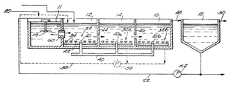
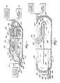
- FIG. 1is a schematic view of an improved wastewater treatment system embodying the invention.
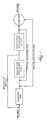
- FIG. 2is a schematic and diagrammatic top plan view of an improved wastewater treatment system embodying the invention.
- FIG. 3is a schematic and diagrammatic side plan view of the system illustrated in FIG. 2 .
- FIG. 4is a fragmentary, top plan view of a bottom portion of the first channel shown in FIG. 3 and including fine bubble membrane diffusers.
- FIG. 5is an enlarged fragmentary view of a diffuser shown in FIG. 4 .
- FIG. 7is a side view of the reactor shown in FIG. 6 .
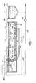
- FIG. 8is a side perspective elevation view of a system including a series of vertical loop reactors downstream from an anaerobic zone.
- FIG. 9is a top plan view of the system shown in FIG. 8 .
- denitrified mixed liquor from a downstream aeration zone having a continuous oxygen deficit(defined below) is added to the anaerobic zone.
- the denitrified mixed liquoris added at a rate from 0.5 to 2 times the wastewater influent flow rate.
- micro-organismscapable of accumulating quantities of phosophorus in excess of that required for simple cell growth and reproduction take-up and store simple carbon compounds, using energy derived from the hydrolysis and release of polyphosphates.
- the hydraulic residence time in the anaerobic zoneis typically, but not limited to, 0.5 to 2.0 hours.
- aeration zone or tank having a continuous oxygen deficitand “oxygen-deficit aeration zone or tank” are synonymous and meant to refer to a zone having a continuous oxygen deficit maintained, e.g., by controlling the rate of aeration such that the rate of oxygen supply is less than the rate of oxygen consumption by the micro-organisms in the tank. This results in dissolved oxygen concentrations at or near zero throughout the basin.
- Aeration zone having a continuous oxygen deficit” and “oxygen-deficit aeration zone”are also meant to refer to an aerated anoxic tank or zone, and more particularly to a zone or tank wherein simultaneous nitrification and denitrification take place.
- atmospheric oxygenis supplied to the tank, but does not meet the oxygen demand thereof.
- simultaneous nitrification and denitrificationdo not take place as no atmospheric oxygen is supplied to the tank, i.e. no oxygen is supplied to the tank by aerators.
- Aerator devices(described below), or a combination of aerator devices and mechanical mixers provide oxygen and keep the mixed liquor solids in suspension.
- heterotrophic organismsoxidize BOD and autotrophic organisms oxidize ammonia in the aeration tank having a continuous oxygen deficit.
- the amount of oxygen suppliedis less than the demand and nitrates from oxidation of ammonia are present, heterotrophic organisms will oxidize BOD using nitrates as an electron acceptor and converting nitrates into nitrogen gas.
- the hydraulic residence time in the aeration zone having a continuous oxygen deficitis typically, but not limited to, 2 to 12 hours.
- the effluent from the aeration zone having a continuous oxygen deficitthen flows to one or more downstream tanks having a continuous oxygen surplus.
- the terms “aeration zone or tank having a continuous oxygen surplus” and “oxygen-surplus aeration zone or tank”are meant to refer to a aeration zone wherein the rate of oxygen supply meets or exceeds the demand of micro-organisms in the tank.
- Most of the BOD and ammonia in the wastewaterhas been oxidized by the time the wastewater reaches the last aeration zone, so dissolved oxygen concentrations of 1 mg/L or greater are easily maintained in the last aeration zone. Oxidation of BOD and ammonia occurs in the aeration tanks having a continuous oxygen surplus.
- micro-organismsoxidize the carbon that they have absorbed in the anaerobic zone and absorb and store polyphosphates as an energy source for the return trip back to the anaerobic zone as return activated sludge.
- the hydraulic residence time in the aeration zone having a continuous oxygen surplusis typically, but not limited to, 2 to 12 hours.
- effluent from the aeration tanks having a continuous oxygen surplusflows to the clarifier where the biological solids settle.
- a portion of the effluentmay be returned to the biological process leaving a supernatant with reduced levels of organic matter, phosphorus and nitrogen. This supernatant is removed and becomes the process effluent.
- Some of the settled solidsis removed from the system (waste activated sludge), thereby removing phosphorus and organic matter.
- FIGS. 2 and 3illustrate one embodiment of the improved wastewater treatment system 10 for practicing the activated sludge treatment process of the invention.
- the system 10includes an initial anaerobic zone 11 and a plurality of concentric, annular basins or channels including a first aeration zone having an oxygen deficit 12 , a second aeration zone having an oxygen surplus 14 and, alternatively, a third aeration zone having an oxygen surplus 16 .
- the system 10also includes a settling tank or clarifier 18 .
- a wastewater influentwhich usually is subjected to screening and/or preliminary sedimentation treatment (not shown) to remove large particulate materials, is introduced into the anaerobic zone 11 via a supply conduit 20 and mixed with denitrified-mixed liquor from a downstream aeration zone, e.g. the first aeration zone or channel 12 .
- the wastewater, denitrified-mixed liquor and activated sludgeare mixed in the anaerobic zone 11 by a mechanical mixer 19 , which allows solids in the wastewater to remain suspended without aeration.
- a non-aerated tank or reactoris used typically in the front part of the activated sludge process for biological phosphorus removal where the influent raw sewage flow is mixed and blended with aerobic biomass solids void of oxygen.
- the tankis designed typically to be void both of delivered oxygen (including DO contained in sidestreams) and the oxygen contained in nitrites and nitrates.
- the aerobic biomass solidsPrior to entering these tanks, the aerobic biomass solids are usually routed through anoxic tanks to remove nitrites and nitrates and to remove any DO (dissolved oxygen) contained in the liquid stream. Blankets of nitrogen, carbon dioxide and other gases can also be used to limit the anaerobic zone's access to the atmosphere.
- These anaerobic reactorsare merely illustrative, and should not be construed to limit the types of anaerobic zones which can be used in conjunction with the methods described herein. In other words, any anaerobic zone which is maintained under anaerobic conditions is suitable for use with the system.
- the denitrified-mixed liquoris added from a continuous-oxygen-deficit aeration zone (e.g. the first channel 12 ) to the anaerobic zone 11 as shown by arrow 60 in FIGS. 2 and 3.
- Denitrified-mixed liquoris a product of aerating and mixing wastewater influent with activated sludge under continuous-oxygen-deficit conditions.
- the denitrified-mixed liquoris added at rate that is about 0.5 to 2 times the wastewater influent flow rate, although other rates can be used.
- the combined wastewater and denitrified-mixed liquorthen flow to one or more downstream aeration tanks having a continuous-oxygen deficit, e.g. first channel 12 .
- the continuous-oxygen deficitis maintained by controlling the rate of aeration such that the rate of oxygen supply is less than the rate of oxygen consumption by the micro-organisms in the tank, thereby resulting in dissolved oxygen concentrations at or near zero throughout the zone.
- Aerator devicesdiscussed below, or a combination of aerator devices and mechanical mixers, provide oxygen and keep the mixed liquor solids in suspension.
- Settled sludgei.e. return activated sludge
- from the clarifier 18can be added to the aeration zone having a continuous-oxygen deficit 12 .
- nitrified-mixed liquor from a downstream aeration zone having an oxygen surplusmay be recycled by a pump 56 through a conduit 58 to the continuous-oxygen-deficit aeration zone 12 as illustrated by dashed lines in FIG. 3 .
- the contents of the first channel 12are mixed therein in part by a plurality of surface aeration devices 24 .
- Each surface aeration device 24includes a plurality of aeration discs 26 mounted on a shaft 28 which is rotated by an electric motor 30 or other suitable driver.
- Each aeration disc 26has a plurality of apertures or recesses (not shown) for catching or entraining air which is dispersed into the mixed liquor as fine bubbles during disc rotation. The rotating aeration discs 26 effectively mix and aerate the upper portion of the mixed liquor and keep the mixed liquor moving around the first channel 12 .
- heterotrophic organismscan oxidize BOD and autotrophic organisms can oxidize ammonia in the aeration tank having a continuous-oxygen deficit. Because the amount of oxygen supplied is less than the demand and because nitrates from oxidation of ammonia are present, heterotrophic organisms will also oxidize BOD using nitrates as an electron acceptor and convert nitrates into nitrogen gas.
- the hydraulic residence time in the aeration zone with a continuous-oxygen deficitis preferably, but should not be limited to, 2 to 12 hours.
- the mixed liquor in the first channel 12may be mixed in part by a plurality of submerged aeration devices 32 which are located in the lower portion of the first channel 12 and produce fine bubbles having a diameter of less than about 4 mm, and preferably about 1 to about 3 mm.
- Submerged aeration devicesare not required by the invention.
- the oxygen-containing gasis introduced by the surface and submerged aeration devices 24 and 32 under conditions which produce a complete mix reaction in the first channel 12 and sufficient oxygen is supplied to meet, but not substantially exceed, the biological oxygen demand of the mixed liquor.
- the dissolved oxygen contentpreferably is maintained at as close to zero as possible. However, because of changing conditions it may periodically fluctuate above and below zero.
- the overall dissolved oxygen content in the first channel 12should not exceed about 0.5 mg/l.
- the oxygen-containing gaspreferably is air and the submerged aeration devices preferably are conventional coarse or fine bubble (fine pore) membrane diffusers 34 having an expandable flexible member 36 including a plurality of perforations 38 through which air is injected into the contents of the first channel 12 .
- the diffusers 34are uniformly distributed in the lower portion of the first channel 12 , either near the bottom or along one side.
- the diffusers 34can be either a pipe type or a disc.
- the diffusers 34serve the dual function of providing part of the oxygen required to meet the biological oxygen demand of the mixed liquor and mixing of the mixed liquor in the lower portion of the first channel 12 .
- the diffusers 34can be operated to provide a substantial part of the mixing required to prevent settling and a substantial part of the oxygen required to meet the biological oxygen demands of the mixed liquor.
- the primary function of the rotating aeration discs 26is to keep the mixed liquor moving around the first channel 12 and the secondary function is to introduce a relatively small amount of air into the mixed liquor. This can result in the reduction of the number of discs and the amount of energy required to operate them.
- the diffusers 34are used more as a supplemental supply of oxygen and to provide supplemental mixing in the lower portion of the first channel 12 , the combined mixing and oxygen provided by the rotating aeration discs 26 and the diffusers 34 permits the first channel to be much deeper than in conventional wastewater treatment processes employing only surface aeration devices. This can result in a reduction in initial system installation costs.
- a plurality of disc-type fine bubble membrane diffusers 34are mounted in a grid-like array in the bottom of the first channel 12 .
- Airis supplied under pressure through a manifold 40 (which may or may not be in fluid communication with other manifolds, e.g., 40 a, 40 b ) connected to a plurality of air supply conduits 42 which are arranged in parallel rows.
- a plurality of longitudinally spaced diffusers 34are mounted on each supply conduit 42 , preferably in an array so that the diffusers on adjacent air supply conduits form rows transverse to the air supply conduits.
- the combined effect of the surface and submerged aeration devicesproduce a complete mix reaction in both the second and third channels 14 and 16 .
- the overall dissolved oxygen content in the second channel 14is preferably at least 0.5 mg/l and preferably greater than about 1.0 mg/l.
- the overall dissolved oxygen content of the third channel 16is preferably at least 2.0 mg/l.
- the mixed liquoris transferred from one of the continuous-oxygen surplus aeration zones, e.g. the second channel 14 or the third channel 16 , into clarifier 18 through a conduit 48 .
- Sludgesettles in the clarifier 18 leaving a clarified effluent or supernatant having reduced levels of organic matter, phosphorus or nitrogen.
- a portion of the supernatantmay be withdrawn from the upper portion of the clarifier via a conduit 50 for further treatment prior to disposal or reuse. This supernatant is removed and becomes the process effluent.
- a portion of the settled sludge withdrawn from the bottom portion of the clarifier 18is recycled by a pump 52 through the conduit 22 back to the first channel 12 as illustrated by solid lines in FIGS. 2 and 3. Another portion of settled sludge is removed via a conduit 54 .
- the amount of activated sludge recycled to the first channel 12usually is about 15 to about 150, preferably about 50 to about 100%, of the wastewater influent introduced through the conduit 20 .
- nitrified mixed liquor from the third channel 16 and/or the second channel 14is recycled by a pump 56 through a conduit 58 as illustrated by dashed lines in FIG. 3 .
- the amount of mixed liquor recycled to the first channelusually is about 100 to about 400% of the wastewater influent being introduced through the conduit 20 .
- anaerobic zonecauses the micro-organisms to release phosphorus, thereby allowing the micro-organisms to take up phosphorus at a much higher rate in the different aeration zones.
- utilizing an anaerobic zonehas been attributed to reducing the phosphorus concentration in treated waters from about 5 mg/l to about 2.5 mg/l.
- a vertical loop reactor (VLR®) systemmodified to include an initial anaerobic zone can be employed.
- VLR®vertical loop reactor
- Suitable anaerobic zones or tanks for use in the modified VLR® systemare set forth above, and can be fluidly connected to the VLR®.
- a suitable vertical loop reactor systemis described below and in U.S. Pat. No. 4,629,559 issued to Smith which is hereby fully incorporated by reference.
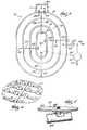
- FIGS. 6-7show in detail an individual vertical loop reactor.
- the VLR®can be installed in a rectangular tank, and is similar to an oxidation ditch that has been flipped on its side. There are upper and lower compartments 132 and 134 , separated by a horizontal baffle 130 running the length of the tank. Commonly, three basins make up a VLR® system.
- the VLR® processis adapted from proven ORBALTM technology and uses the same surface mounted discs or aerators 120 (described above) to provide mixing and to deliver oxygen.
- the typical VLR systemhas two or more rectangular tanks 100 , 102 , 104 placed side by side and operated in series.
- an anaerobic zone 106is followed by a downstream first tank 100 .
- the first tank 100is used as an aerated anoxic reactor, i.e. an aeration zone having a continuous oxygen deficit, in which an oxygen deficit is maintained and the DO level is kept near zero.
- the subsequent VLR tanks 102 , 104are maintained under aerated conditions having a continuous oxygen surplus.
- the initial anaerobic zone 106is followed by a downstream VLR® tank 100 having an oxygen deficit and one or more VLR® tanks having an oxygen surplus 102 and 104 .
- the last tank 104may be operated with a DO level of 2 mg/L or higher.
- FIG. 6depicts a relatively deep wastewater VLR® tank composed of a suitable material such as concrete, synthetic resin, steel, etc.
- the tankis generally of rectangular shape and can vary in size.
- the longer axis of the tankcan vary in length up to about 100-200 feet, while the width may vary from about 50-100 feet.
- the tankhas a liquid depth of about 10-25 feet.
- Raw sewageenters tank 100 through influent conduit 108 into an anaerobic tank or zone 106 .
- Any of the anaerobic tanks or zones described abovecan be employed in the improved VLR® system.
- the wastewater influentis mixed with activated sludge present in the anaerobic tank 106 to form a mixed liquor.
- the mixed liquoris then introduced into a VLR® 100 which acts as an oxygen-deficit aeration zone, i.e. an aeration zone maintained under aerated anoxic conditions as defined above.
- the mixed liquoris then aerated using mechanical aerators 120 so that air bubbles or the like are introduced into the sewage in the upper layer of the tank.
- Aerators 120comprises a plurality of disks 122 mounted on a common axle 124 oriented on a transverse axis to the flow of sewage and designed to rotate at least partially in contact with the mixed liquor entering tank 100 via influent conduit 112 .
- a portion of this denitrified-mixed liquor from the oxygen-deficit zone 100may be recycled to the anaerobic zone 106 for mixing therein with wastewater.
- the axle 124is operationally connected to a rotator 126 such as an electric motor.
- the disks 122are provided with a plurality of fine perforations and depressions 128 which function not only to carry air bubbles into and below the surface of the sewage liquor but also to trap subsurface liquid therein and carry drops thereof upwardly into contact with the ambient air.
- a plurality of mechanical aerators 120 and the speed of rotationmay be varied to suit the operational conditions of the tank 100 and the incoming sewage. The mechanical aerators 120 thus introduces air below the surface of the liquid in tank 100 and provides surface energy through flow agitation of the sewage to prevent settling out of sewage solids.
- a baffle-like member 130is mounted within the tank below the normal liquid level approximately horizontally dividing the interior of tank 100 into a plurality of equal volume flow passageways in the preferred embodiment comprising an upper flow passageway 132 and a lower flow passageway 134 . As will be shown below in FIG. 9, more than two flow passageways may be provided without deviating from the spirit of the invention.
- the baffle-like member 130is gas-impermeable and may be composed of any rigid material such as metal or synthetic resin, but corrosion resistant characteristics are preferred.
- the baffle membermay be formed in corrugated fashion, as shown, or in other fashion to increase its strength. The corrugation performs the additional function of preventing air bubbles from forming a film or otherwise congregating underneath the baffle-like member 130 .
- aerator 120functions generally in a plane parallel to the direction of flow and introduces air and flow energy into the sewage.
- mechanical aerators 120perform the dual function of mixing air into the mixed liquor by drawing oxygen depleted sewage into the air and by pulling air into the wastewater.
- Mechanical aerators 120also create a tank flow pattern in flow passageways 132 and 134 of an adequate velocity necessary to maintain the waste solids in a suspended condition. The waste solids must remain suspended as long as possible to enable the microscopic biota to optimally encounter and digest the organic waste compounds.
- This directional flow created by mechanical aerator 120is aided by the geometry of the inner tank surface with its curved end walls 131 , and travels along the entire length of the upper flow passageways 132 into the lower flow passageway 134 and then back into the upper flow passageway 132 .
- the flow of wastewatercarries air in the form of trapped bubbles along this cyclical path from the upper 132 to the lower flow passageway 134 , where the oxygen component of the air is dissolved within the sewage liquors and is depleted by the active organisms contained in the water.
- the nature of the flow cycleis such that as a particular portion of liquid wastewater travels through the upper and lower passageways 132 and 134 , it will be gradually depleted of its supply of oxygen from the point at which it leaves the mechanical aerator 120 , until it encounters another aerator or returns to the starting point.
- the oxygen depleted nature of the wastewater as it encounters the aerator 120significantly increases the efficiency of the device by facilitating the absorption of oxygen.
- Secondary baffle 150is comprised of a curved gas capture portion 152 and a substantially horizontal gas release portion 154 having a plurality of randomly spaced gas release apertures 156 .
- the secondary baffle 150is positioned in the tank 100 above baffle-like member 130 to create a narrow chamber 158 , said chamber having a height on the order of 1-2 feet.
- Secondary baffle 150is further positioned in tank 100 near the end of baffle-like member 130 so that the curved gas capture portion 152 can intercept the large bubbles 143 as they escape from underneath baffle-like member 130 .
- the large bubbles 143then flow into narrow chamber 158 , where their natural tendency to rise to the surface forces them through the smaller gas release apertures 156 .
- the gas release apertures 156are constructed and arranged to create small bubbles 160 of the approximate size of bubbles emitted from a coarse bubble diffuser device which is standard in the industry, or on the order of one-quarter to 0.178 inch in diameter. This creation of a plurality of small bubbles 160 from the large bubbles 143 in chamber 158 significantly increases the oxygen transfer efficiency of the system by providing additional air/liquid surface area.
- gas release portion 154is oriented substantially parallel with baffle-like member 130 and extends longitudinally away from the gas capture portion approximately 15-30% of the length of baffle-like member 130 .
- the exact position of secondary baffle 150may vary as long as its air capture function is not impaired and the flow of sewage liquor in flow passageway 132 is not impeded. Small bubbles 160 are released into the upper flow passageway 132 on an angular trajectory as they are carried into the moving flow of wastewater.
- VLR®'s 102 or 104having continuous oxygen surplus as defined above.
- the actual structure of the subsequent tanksis similar to the VLR® described above, except that it is maintained under conditions which provide an oxygen surplus.
- Effluentflows from tank 100 to 102 by conduit 164 , and from tank 102 to tank 104 by conduit 168 .
- the second VLR® 102has a dissolved oxygen concentration of 1 mg/L or greater and the third VLR® 104 has an overall dissolved oxygen concentration of 2 mg/L or greater.
- the effluentproceeds from the outlet 172 to a final clarifier (not shown) wherein sludge is removed for ultimate disposal and/or recycling by mixing with fresh raw sewage.
- the remaining effluentis clarified and otherwise treated to yield useful water which can be discharged into streams or the like.
- a portion of the settled sludgeis recycled to the aerated VLR® having oxygen deficit as recycled activated sludge.
Landscapes
- Life Sciences & Earth Sciences (AREA)
- Biodiversity & Conservation Biology (AREA)
- Microbiology (AREA)
- Hydrology & Water Resources (AREA)
- Engineering & Computer Science (AREA)
- Environmental & Geological Engineering (AREA)
- Water Supply & Treatment (AREA)
- Chemical & Material Sciences (AREA)
- Organic Chemistry (AREA)
- Health & Medical Sciences (AREA)
- Molecular Biology (AREA)
- Purification Treatments By Anaerobic Or Anaerobic And Aerobic Bacteria Or Animals (AREA)
Abstract
Description
Claims (20)
Priority Applications (1)
| Application Number | Priority Date | Filing Date | Title |
|---|---|---|---|
| US09/941,535US6592762B2 (en) | 2001-08-29 | 2001-08-29 | Process for treating BOD-containing wastewater |
Applications Claiming Priority (1)
| Application Number | Priority Date | Filing Date | Title |
|---|---|---|---|
| US09/941,535US6592762B2 (en) | 2001-08-29 | 2001-08-29 | Process for treating BOD-containing wastewater |
Publications (2)
| Publication Number | Publication Date |
|---|---|
| US20030042199A1 US20030042199A1 (en) | 2003-03-06 |
| US6592762B2true US6592762B2 (en) | 2003-07-15 |
Family
ID=25476654
Family Applications (1)
| Application Number | Title | Priority Date | Filing Date |
|---|---|---|---|
| US09/941,535Expired - LifetimeUS6592762B2 (en) | 2001-08-29 | 2001-08-29 | Process for treating BOD-containing wastewater |
Country Status (1)
| Country | Link |
|---|---|
| US (1) | US6592762B2 (en) |
Cited By (68)
| Publication number | Priority date | Publication date | Assignee | Title |
|---|---|---|---|---|
| US20040094475A1 (en)* | 2002-11-14 | 2004-05-20 | Stephen Hough | Waste activated sludge anaerobic contact waste stream treatment process |
| US20050098496A1 (en)* | 2003-11-11 | 2005-05-12 | Hamann Ag | Process and assembly for the treatment of waste water on ships |
| US20060027495A1 (en)* | 2004-08-05 | 2006-02-09 | Hough Stephen G | Waste activated sludge anaerobic contact waste stream treatment process-recycle |
| US20070000836A1 (en)* | 2005-06-30 | 2007-01-04 | Usfilter Corporation | Process to enhance phosphorus removal for activated sludge wastewater treatment systems |
| US20070051677A1 (en)* | 2005-09-02 | 2007-03-08 | Siemens Water Technologies Corp. | Screening of inert solids from a low-yield wastewater treatment process |
| US20070138090A1 (en)* | 2005-10-05 | 2007-06-21 | Jordan Edward J | Method and apparatus for treating wastewater |
| US20070209998A1 (en)* | 2006-03-07 | 2007-09-13 | Siemens Water Technologies Corp. | Multivalent Metal Ion Management for Low Sludge Processes |
| US20070235386A1 (en)* | 2006-04-11 | 2007-10-11 | Barnes Dennis J | Process to improve the efficiency of a membrane filter activated sludge system |
| US20070235385A1 (en)* | 2006-04-11 | 2007-10-11 | Barnes Dennis J | Aerated Anoxic Membrane Bioreactor |
| US20080041783A1 (en)* | 2006-04-11 | 2008-02-21 | Barnes Dennis J | Process to Improve The Efficiency of a Membrane Filter Activated Sludge System |
| US20080116130A1 (en)* | 2005-01-31 | 2008-05-22 | Ashbrook Simon-Hartley Operations, Lp | Methods and apparatus for treating wastewater employing a high rate clarifier and a membrane |
| US20080314837A1 (en)* | 2007-06-19 | 2008-12-25 | Vanotti Matias B | Wastewater treatment system with simultaneous separation of phosphorus and manure solids |
| CN101445295A (en)* | 2008-12-11 | 2009-06-03 | 上海市政工程设计研究总院 | Biological-activity monitoring device for monitoring abnormal operation of sewage disposal system and monitoring method thereof |
| US7632439B2 (en) | 2002-02-12 | 2009-12-15 | Siemens Water Technologies Corp. | Poly(ethylene chlorotrifluoroethylene) membranes |
| US20100155328A1 (en)* | 2007-05-10 | 2010-06-24 | O'regan Jr Patrick T | Systems, methods and components for water treatment and remediation |
| US7780833B2 (en) | 2005-07-26 | 2010-08-24 | John Hawkins | Electrochemical ion exchange with textured membranes and cartridge |
| US7938966B2 (en) | 2002-10-10 | 2011-05-10 | Siemens Water Technologies Corp. | Backwash method |
| US7959780B2 (en) | 2004-07-26 | 2011-06-14 | Emporia Capital Funding Llc | Textured ion exchange membranes |
| US20110210049A1 (en)* | 2008-11-02 | 2011-09-01 | O'regan Jr Patrick T | Water treatment systems with communication network links and methods |
| US8048306B2 (en) | 1996-12-20 | 2011-11-01 | Siemens Industry, Inc. | Scouring method |
| US8182687B2 (en) | 2002-06-18 | 2012-05-22 | Siemens Industry, Inc. | Methods of minimising the effect of integrity loss in hollow fibre membrane modules |
| US20120132587A1 (en)* | 2006-09-05 | 2012-05-31 | Aeration Industries International LLC | Wastewater treatment system |
| US20120152832A1 (en)* | 2008-12-22 | 2012-06-21 | University Of Utah Research Foundation | Submerged system and method for removal of undesirable substances from aqueous media |
| US8268176B2 (en) | 2003-08-29 | 2012-09-18 | Siemens Industry, Inc. | Backwash |
| US8287743B2 (en) | 2007-05-29 | 2012-10-16 | Siemens Industry, Inc. | Membrane cleaning with pulsed airlift pump |
| US8293098B2 (en) | 2006-10-24 | 2012-10-23 | Siemens Industry, Inc. | Infiltration/inflow control for membrane bioreactor |
| US8318028B2 (en) | 2007-04-02 | 2012-11-27 | Siemens Industry, Inc. | Infiltration/inflow control for membrane bioreactor |
| US8377305B2 (en) | 2004-09-15 | 2013-02-19 | Siemens Industry, Inc. | Continuously variable aeration |
| US8382981B2 (en) | 2008-07-24 | 2013-02-26 | Siemens Industry, Inc. | Frame system for membrane filtration modules |
| US8496828B2 (en) | 2004-12-24 | 2013-07-30 | Siemens Industry, Inc. | Cleaning in membrane filtration systems |
| US8506806B2 (en) | 2004-09-14 | 2013-08-13 | Siemens Industry, Inc. | Methods and apparatus for removing solids from a membrane module |
| US8512568B2 (en) | 2001-08-09 | 2013-08-20 | Siemens Industry, Inc. | Method of cleaning membrane modules |
| US8518256B2 (en) | 2001-04-04 | 2013-08-27 | Siemens Industry, Inc. | Membrane module |
| US8562803B2 (en) | 2005-10-06 | 2013-10-22 | Pionetics Corporation | Electrochemical ion exchange treatment of fluids |
| US8623213B2 (en) | 2008-03-28 | 2014-01-07 | Siemens Water Technologies Llc | Hybrid aerobic and anaerobic wastewater and sludge treatment systems and methods |
| US8652331B2 (en) | 2008-08-20 | 2014-02-18 | Siemens Water Technologies Llc | Membrane system backwash energy efficiency |
| WO2014043547A1 (en)* | 2012-09-13 | 2014-03-20 | D.C. Water & Sewer & Authority | Method and apparatus for nitrogen removal in wastewater treatment |
| US8685247B2 (en) | 2009-12-03 | 2014-04-01 | Evoqua Water Technologies Llc | Systems and methods for nutrient removal in biological treatment systems |
| US8758622B2 (en) | 2004-12-24 | 2014-06-24 | Evoqua Water Technologies Llc | Simple gas scouring method and apparatus |
| US8758621B2 (en) | 2004-03-26 | 2014-06-24 | Evoqua Water Technologies Llc | Process and apparatus for purifying impure water using microfiltration or ultrafiltration in combination with reverse osmosis |
| US8790515B2 (en) | 2004-09-07 | 2014-07-29 | Evoqua Water Technologies Llc | Reduction of backwash liquid waste |
| US8801931B2 (en) | 2010-02-25 | 2014-08-12 | Evoqua Water Technologies Llc | Hybrid aerobic and anaerobic wastewater and sludge treatment systems and methods |
| US8808540B2 (en) | 2003-11-14 | 2014-08-19 | Evoqua Water Technologies Llc | Module cleaning method |
| US8808544B2 (en) | 2010-08-18 | 2014-08-19 | Evoqua Water Technologies Llc | Contact-stabilization/prime-float hybrid |
| US8858796B2 (en) | 2005-08-22 | 2014-10-14 | Evoqua Water Technologies Llc | Assembly for water filtration using a tube manifold to minimise backwash |
| US8894857B2 (en) | 2008-03-28 | 2014-11-25 | Evoqua Water Technologies Llc | Methods and systems for treating wastewater |
| US8956464B2 (en) | 2009-06-11 | 2015-02-17 | Evoqua Water Technologies Llc | Method of cleaning membranes |
| US20150111271A1 (en)* | 2011-10-19 | 2015-04-23 | Anaergia Inc. | Multiple tank high solids anaerobic digester |
| US9022224B2 (en) | 2010-09-24 | 2015-05-05 | Evoqua Water Technologies Llc | Fluid control manifold for membrane filtration system |
| US9340439B2 (en) | 2012-09-13 | 2016-05-17 | D.C. Water & Sewer Authority | Method and apparatus for nitrogen removal in wastewater treatment |
| US9359236B2 (en) | 2010-08-18 | 2016-06-07 | Evoqua Water Technologies Llc | Enhanced biosorption of wastewater organics using dissolved air flotation with solids recycle |
| WO2016053456A3 (en)* | 2014-10-03 | 2016-08-25 | Evoqua Water Technologies Llc | Wastewater treatment system |
| US9533261B2 (en) | 2012-06-28 | 2017-01-03 | Evoqua Water Technologies Llc | Potting method |
| US9604166B2 (en) | 2011-09-30 | 2017-03-28 | Evoqua Water Technologies Llc | Manifold arrangement |
| US9675938B2 (en) | 2005-04-29 | 2017-06-13 | Evoqua Water Technologies Llc | Chemical clean for membrane filter |
| US9757695B2 (en) | 2015-01-03 | 2017-09-12 | Pionetics Corporation | Anti-scale electrochemical apparatus with water-splitting ion exchange membrane |
| US9764289B2 (en) | 2012-09-26 | 2017-09-19 | Evoqua Water Technologies Llc | Membrane securement device |
| US9764288B2 (en) | 2007-04-04 | 2017-09-19 | Evoqua Water Technologies Llc | Membrane module protection |
| US9815027B2 (en) | 2012-09-27 | 2017-11-14 | Evoqua Water Technologies Llc | Gas scouring apparatus for immersed membranes |
| US9914097B2 (en) | 2010-04-30 | 2018-03-13 | Evoqua Water Technologies Llc | Fluid flow distribution device |
| US9925499B2 (en) | 2011-09-30 | 2018-03-27 | Evoqua Water Technologies Llc | Isolation valve with seal for end cap of a filtration system |
| US9962865B2 (en) | 2012-09-26 | 2018-05-08 | Evoqua Water Technologies Llc | Membrane potting methods |
| US10131550B2 (en) | 2013-05-06 | 2018-11-20 | Evoqua Water Technologies Llc | Enhanced biosorption of wastewater organics using dissolved air flotation with solids recycle |
| CN109133532A (en)* | 2018-10-10 | 2019-01-04 | 浙江博华环境技术工程有限公司 | A kind of process for town sewage treatment being applicable in quasi- IV class water quality standard |
| CN109368785A (en)* | 2018-11-05 | 2019-02-22 | 宁波水思清环境科技有限公司 | A kind of denitrification denitrogenation microbiologic population and its application |
| US10322375B2 (en) | 2015-07-14 | 2019-06-18 | Evoqua Water Technologies Llc | Aeration device for filtration system |
| US10427102B2 (en) | 2013-10-02 | 2019-10-01 | Evoqua Water Technologies Llc | Method and device for repairing a membrane filtration module |
| US10532940B2 (en) | 2014-09-16 | 2020-01-14 | Evoqua Water Technologies Llc | Aeration discs and methods for using same |
Families Citing this family (17)
| Publication number | Priority date | Publication date | Assignee | Title |
|---|---|---|---|---|
| US7172699B1 (en)* | 2004-10-13 | 2007-02-06 | Eimco Water Technologies Llc | Energy efficient wastewater treatment for nitrogen and phosphorus removal |
| EP1829827A1 (en)* | 2006-03-03 | 2007-09-05 | LINDE-KCA-Dresden GmbH | Process for the biological purification of wastewater with simultaneous degradation of organic and nitrogen containing compounds |
| US7767088B2 (en)* | 2006-12-05 | 2010-08-03 | Jet, Inc. | Water treatment clarifier baffle |
| ES2379934B1 (en)* | 2009-03-20 | 2013-03-22 | Estela Potente Sancho | SEQUENTIAL NUTRIENT CLEANING SYSTEM WITH TELEMATIC CONTROL. |
| CN102211837A (en)* | 2011-03-04 | 2011-10-12 | 扬州大学 | Method for treating urban sewage through water step-feed multi-stage aeration biological denitrification and biological filter |
| KR101068579B1 (en)* | 2011-07-15 | 2011-09-30 | 한국과학기술연구원 | Alternating Aeration Wastewater Treatment System and Method Using Ceramic Membrane |
| KR101414769B1 (en)* | 2012-11-28 | 2014-07-03 | 한국과학기술연구원 | Apparatus and method for cultivating micro-algae with sludge treatment effluent |
| CN106915825B (en)* | 2017-03-31 | 2020-03-13 | 北京工业大学 | Device and method for promoting nitrosation-anaerobic ammonia oxidation granulation of UMABR reactor |
| CN107032488B (en)* | 2017-04-24 | 2020-07-31 | 北京工业大学 | A method for realizing short-range nitrification of urban sewage through sludge double-return AOA process |
| TWI760562B (en) | 2017-09-14 | 2022-04-11 | 美商伊芙卡水科技有限公司 | Simultaneous nitrification/denitrification (sndn) in sequencing batch reactor applications |
| US11155482B2 (en) | 2018-04-04 | 2021-10-26 | Somerset Environmental Solutions Inc. | Apparatus and method for aerating wastewater |
| WO2019236589A1 (en)* | 2018-06-05 | 2019-12-12 | Evoqua Water Technologies Llc | Combination of dissolved air flotation and fixed film bioreactor solutions |
| CN111217451B (en)* | 2020-02-25 | 2024-07-09 | 中冶赛迪技术研究中心有限公司 | Integrated AO biomembrane reactor |
| CN112875849B (en)* | 2021-01-27 | 2022-11-29 | 清华苏州环境创新研究院 | Integrated sewage treatment device with inclined plate oxidation ditch |
| CN113896326B (en)* | 2021-12-09 | 2022-05-10 | 清研环境科技股份有限公司 | Sewage treatment reactor and treatment method thereof |
| CN115196749A (en)* | 2022-07-11 | 2022-10-18 | 常州大学 | An Anoxic-Orbal Combined Device for Treating Mixed Sewage |
| CN115594296B (en)* | 2022-11-12 | 2023-09-08 | 广州全康环保设备有限公司 | Sewage treatment equipment and process for synchronous aerobic biochemical treatment and solid-liquid separation |
Citations (20)
| Publication number | Priority date | Publication date | Assignee | Title |
|---|---|---|---|---|
| US2430519A (en)* | 1942-03-19 | 1947-11-11 | Edward B Mallory | Regenerative digester |
| US2441813A (en)* | 1940-02-17 | 1948-05-18 | Halvorson Halvor Orin | Process and system for treating sewage |
| US3764523A (en) | 1972-05-01 | 1973-10-09 | Union Carbide Corp | Nitrification of bod-containing water |
| US3900394A (en)* | 1972-06-06 | 1975-08-19 | Activox Inc | Process for total sewage treatment |
| US3939068A (en) | 1973-12-06 | 1976-02-17 | The United States Of America As Represented By The Secretary Of The Army | Process for treating waste water containing cellulose nitrate particles |
| US3953327A (en) | 1973-04-26 | 1976-04-27 | Central Contra Costa Sanitary District | Sewage treatment process |
| US3964998A (en) | 1972-08-04 | 1976-06-22 | The South African Inventions Development Corporation | Improvements in and relating to waste water treatment |
| US3994802A (en) | 1975-04-16 | 1976-11-30 | Air Products And Chemicals, Inc. | Removal of BOD and nitrogenous pollutants from wastewaters |
| US4056465A (en) | 1976-04-12 | 1977-11-01 | Air Products And Chemicals, Inc. | Production of non-bulking activated sludge |
| US4162153A (en)* | 1976-04-12 | 1979-07-24 | Air Products And Chemicals, Inc. | High nitrogen and phosphorous content biomass produced by treatment of a BOD-containing material |
| US4315821A (en)* | 1975-01-06 | 1982-02-16 | Du Pont Canada Inc. | Treatment of nitrogenous wastes |
| US4629559A (en) | 1985-06-12 | 1986-12-16 | Envirex Inc. | Vertical looped reactor tank with delayed air release feature |
| US4867883A (en) | 1987-04-21 | 1989-09-19 | Hampton Roads Sanitation District Of The Commonwealth Of Virginia | High-rate biological waste water treatment process using activated sludge recycle |
| US4961854A (en) | 1988-06-30 | 1990-10-09 | Envirex Inc. | Activated sludge wastewater treatment process |
| US4975197A (en) | 1989-05-03 | 1990-12-04 | Envirex Inc. | Orbal wastewater treatment process |
| US5480548A (en) | 1993-12-28 | 1996-01-02 | Ch2M Hill, Inc. | Wastewater biological phosphorus removal process |
| US5531896A (en)* | 1991-07-12 | 1996-07-02 | Norihito Tambo | Process for disposing of waste water |
| EP0849230A1 (en)* | 1996-12-17 | 1998-06-24 | Krüger, Inc. | Dual-stage biological process for removing nitrogen from wastewater |
| US5824222A (en)* | 1995-11-08 | 1998-10-20 | Micronair, Llc | Method for removing suspended inert solids from a waste stream |
| US6406629B1 (en)* | 1999-07-20 | 2002-06-18 | Zenon Environmental Inc. | Biological process for removing phosphorous involving a membrane filter |
- 2001
- 2001-08-29USUS09/941,535patent/US6592762B2/ennot_activeExpired - Lifetime
Patent Citations (20)
| Publication number | Priority date | Publication date | Assignee | Title |
|---|---|---|---|---|
| US2441813A (en)* | 1940-02-17 | 1948-05-18 | Halvorson Halvor Orin | Process and system for treating sewage |
| US2430519A (en)* | 1942-03-19 | 1947-11-11 | Edward B Mallory | Regenerative digester |
| US3764523A (en) | 1972-05-01 | 1973-10-09 | Union Carbide Corp | Nitrification of bod-containing water |
| US3900394A (en)* | 1972-06-06 | 1975-08-19 | Activox Inc | Process for total sewage treatment |
| US3964998A (en) | 1972-08-04 | 1976-06-22 | The South African Inventions Development Corporation | Improvements in and relating to waste water treatment |
| US3953327A (en) | 1973-04-26 | 1976-04-27 | Central Contra Costa Sanitary District | Sewage treatment process |
| US3939068A (en) | 1973-12-06 | 1976-02-17 | The United States Of America As Represented By The Secretary Of The Army | Process for treating waste water containing cellulose nitrate particles |
| US4315821A (en)* | 1975-01-06 | 1982-02-16 | Du Pont Canada Inc. | Treatment of nitrogenous wastes |
| US3994802A (en) | 1975-04-16 | 1976-11-30 | Air Products And Chemicals, Inc. | Removal of BOD and nitrogenous pollutants from wastewaters |
| US4056465A (en) | 1976-04-12 | 1977-11-01 | Air Products And Chemicals, Inc. | Production of non-bulking activated sludge |
| US4162153A (en)* | 1976-04-12 | 1979-07-24 | Air Products And Chemicals, Inc. | High nitrogen and phosphorous content biomass produced by treatment of a BOD-containing material |
| US4629559A (en) | 1985-06-12 | 1986-12-16 | Envirex Inc. | Vertical looped reactor tank with delayed air release feature |
| US4867883A (en) | 1987-04-21 | 1989-09-19 | Hampton Roads Sanitation District Of The Commonwealth Of Virginia | High-rate biological waste water treatment process using activated sludge recycle |
| US4961854A (en) | 1988-06-30 | 1990-10-09 | Envirex Inc. | Activated sludge wastewater treatment process |
| US4975197A (en) | 1989-05-03 | 1990-12-04 | Envirex Inc. | Orbal wastewater treatment process |
| US5531896A (en)* | 1991-07-12 | 1996-07-02 | Norihito Tambo | Process for disposing of waste water |
| US5480548A (en) | 1993-12-28 | 1996-01-02 | Ch2M Hill, Inc. | Wastewater biological phosphorus removal process |
| US5824222A (en)* | 1995-11-08 | 1998-10-20 | Micronair, Llc | Method for removing suspended inert solids from a waste stream |
| EP0849230A1 (en)* | 1996-12-17 | 1998-06-24 | Krüger, Inc. | Dual-stage biological process for removing nitrogen from wastewater |
| US6406629B1 (en)* | 1999-07-20 | 2002-06-18 | Zenon Environmental Inc. | Biological process for removing phosphorous involving a membrane filter |
Non-Patent Citations (2)
| Title |
|---|
| U.S. Filter/Envirex; The Orbal System for Biological Treatment; Aug. 1997; Bulletin No. U.S.F. 315-151R3; U.S. Filter/Envirex, Waukesha, WI, USA. |
| U.S. Filter/Envirex; Vertical Loop Reactor For Biological Treatment; Feb. 1998; Bulletin No. U.S.F. 315-15A1-R1; U.S. Filter/Envirex; Waukesha, WI, USA. |
Cited By (109)
| Publication number | Priority date | Publication date | Assignee | Title |
|---|---|---|---|---|
| US8048306B2 (en) | 1996-12-20 | 2011-11-01 | Siemens Industry, Inc. | Scouring method |
| US8518256B2 (en) | 2001-04-04 | 2013-08-27 | Siemens Industry, Inc. | Membrane module |
| US8512568B2 (en) | 2001-08-09 | 2013-08-20 | Siemens Industry, Inc. | Method of cleaning membrane modules |
| US7632439B2 (en) | 2002-02-12 | 2009-12-15 | Siemens Water Technologies Corp. | Poly(ethylene chlorotrifluoroethylene) membranes |
| US8182687B2 (en) | 2002-06-18 | 2012-05-22 | Siemens Industry, Inc. | Methods of minimising the effect of integrity loss in hollow fibre membrane modules |
| US7938966B2 (en) | 2002-10-10 | 2011-05-10 | Siemens Water Technologies Corp. | Backwash method |
| US6921486B2 (en)* | 2002-11-14 | 2005-07-26 | Stephen Hough | Waste activated sludge anaerobic contact waste stream treatment process |
| AU2003287662B2 (en)* | 2002-11-14 | 2009-08-13 | Wasac Llc | Waste activated sludge anaerobic contact waste stream treatment process |
| US20040094475A1 (en)* | 2002-11-14 | 2004-05-20 | Stephen Hough | Waste activated sludge anaerobic contact waste stream treatment process |
| US8268176B2 (en) | 2003-08-29 | 2012-09-18 | Siemens Industry, Inc. | Backwash |
| US20050098496A1 (en)* | 2003-11-11 | 2005-05-12 | Hamann Ag | Process and assembly for the treatment of waste water on ships |
| US7235178B2 (en)* | 2003-11-11 | 2007-06-26 | Hamann Ag | Process and assembly for the treatment of waste water on ships |
| US8808540B2 (en) | 2003-11-14 | 2014-08-19 | Evoqua Water Technologies Llc | Module cleaning method |
| US8758621B2 (en) | 2004-03-26 | 2014-06-24 | Evoqua Water Technologies Llc | Process and apparatus for purifying impure water using microfiltration or ultrafiltration in combination with reverse osmosis |
| US7959780B2 (en) | 2004-07-26 | 2011-06-14 | Emporia Capital Funding Llc | Textured ion exchange membranes |
| US20060027495A1 (en)* | 2004-08-05 | 2006-02-09 | Hough Stephen G | Waste activated sludge anaerobic contact waste stream treatment process-recycle |
| US8790515B2 (en) | 2004-09-07 | 2014-07-29 | Evoqua Water Technologies Llc | Reduction of backwash liquid waste |
| US8506806B2 (en) | 2004-09-14 | 2013-08-13 | Siemens Industry, Inc. | Methods and apparatus for removing solids from a membrane module |
| US8377305B2 (en) | 2004-09-15 | 2013-02-19 | Siemens Industry, Inc. | Continuously variable aeration |
| US8758622B2 (en) | 2004-12-24 | 2014-06-24 | Evoqua Water Technologies Llc | Simple gas scouring method and apparatus |
| US8496828B2 (en) | 2004-12-24 | 2013-07-30 | Siemens Industry, Inc. | Cleaning in membrane filtration systems |
| US7410584B2 (en) | 2005-01-31 | 2008-08-12 | Ashbrook Simon-Hartley Operations, Lp | Methods and apparatus for treating wastewater employing a high rate clarifier and a membrane |
| US20080116130A1 (en)* | 2005-01-31 | 2008-05-22 | Ashbrook Simon-Hartley Operations, Lp | Methods and apparatus for treating wastewater employing a high rate clarifier and a membrane |
| US9675938B2 (en) | 2005-04-29 | 2017-06-13 | Evoqua Water Technologies Llc | Chemical clean for membrane filter |
| US7344643B2 (en) | 2005-06-30 | 2008-03-18 | Siemens Water Technologies Holding Corp. | Process to enhance phosphorus removal for activated sludge wastewater treatment systems |
| US20070000836A1 (en)* | 2005-06-30 | 2007-01-04 | Usfilter Corporation | Process to enhance phosphorus removal for activated sludge wastewater treatment systems |
| US8293085B2 (en) | 2005-07-26 | 2012-10-23 | Pionetics Corporation | Cartridge having textured membrane |
| US7780833B2 (en) | 2005-07-26 | 2010-08-24 | John Hawkins | Electrochemical ion exchange with textured membranes and cartridge |
| US8894858B1 (en) | 2005-08-22 | 2014-11-25 | Evoqua Water Technologies Llc | Method and assembly for water filtration using a tube manifold to minimize backwash |
| US8858796B2 (en) | 2005-08-22 | 2014-10-14 | Evoqua Water Technologies Llc | Assembly for water filtration using a tube manifold to minimise backwash |
| US7569147B2 (en) | 2005-09-02 | 2009-08-04 | Siemens Water Technologies Corp. | Screening of inert solids from a low-yield wastewater treatment process |
| US20070051677A1 (en)* | 2005-09-02 | 2007-03-08 | Siemens Water Technologies Corp. | Screening of inert solids from a low-yield wastewater treatment process |
| US20070138090A1 (en)* | 2005-10-05 | 2007-06-21 | Jordan Edward J | Method and apparatus for treating wastewater |
| US8562803B2 (en) | 2005-10-06 | 2013-10-22 | Pionetics Corporation | Electrochemical ion exchange treatment of fluids |
| US9090493B2 (en) | 2005-10-06 | 2015-07-28 | Pionetics Corporation | Electrochemical ion exchange treatment of fluids |
| US7473364B2 (en) | 2006-03-07 | 2009-01-06 | Siemens Water Technologies Corp. | Multivalent metal ion management for low sludge processes |
| US20070209998A1 (en)* | 2006-03-07 | 2007-09-13 | Siemens Water Technologies Corp. | Multivalent Metal Ion Management for Low Sludge Processes |
| US7481933B2 (en)* | 2006-04-11 | 2009-01-27 | Siemens Water Technologies Corporation | Process to improve the efficiency of a membrane filter activated sludge system |
| US7713413B2 (en)* | 2006-04-11 | 2010-05-11 | Siemens Water Technologies Corp. | Aerated anoxic membrane bioreactor |
| US20080041783A1 (en)* | 2006-04-11 | 2008-02-21 | Barnes Dennis J | Process to Improve The Efficiency of a Membrane Filter Activated Sludge System |
| US20070235385A1 (en)* | 2006-04-11 | 2007-10-11 | Barnes Dennis J | Aerated Anoxic Membrane Bioreactor |
| US20070235386A1 (en)* | 2006-04-11 | 2007-10-11 | Barnes Dennis J | Process to improve the efficiency of a membrane filter activated sludge system |
| US8236174B2 (en)* | 2006-09-05 | 2012-08-07 | Aeration Industries International LLC | Wastewater treatment system |
| US20120132587A1 (en)* | 2006-09-05 | 2012-05-31 | Aeration Industries International LLC | Wastewater treatment system |
| US8293098B2 (en) | 2006-10-24 | 2012-10-23 | Siemens Industry, Inc. | Infiltration/inflow control for membrane bioreactor |
| US8623202B2 (en) | 2007-04-02 | 2014-01-07 | Siemens Water Technologies Llc | Infiltration/inflow control for membrane bioreactor |
| US8318028B2 (en) | 2007-04-02 | 2012-11-27 | Siemens Industry, Inc. | Infiltration/inflow control for membrane bioreactor |
| US9764288B2 (en) | 2007-04-04 | 2017-09-19 | Evoqua Water Technologies Llc | Membrane module protection |
| US20100155328A1 (en)* | 2007-05-10 | 2010-06-24 | O'regan Jr Patrick T | Systems, methods and components for water treatment and remediation |
| US8246829B2 (en) | 2007-05-10 | 2012-08-21 | O'regan Jr Patrick T | Systems and methods for water treatment and remediation |
| US9206057B2 (en) | 2007-05-29 | 2015-12-08 | Evoqua Water Technologies Llc | Membrane cleaning with pulsed airlift pump |
| US8622222B2 (en) | 2007-05-29 | 2014-01-07 | Siemens Water Technologies Llc | Membrane cleaning with pulsed airlift pump |
| US8287743B2 (en) | 2007-05-29 | 2012-10-16 | Siemens Industry, Inc. | Membrane cleaning with pulsed airlift pump |
| US9573824B2 (en) | 2007-05-29 | 2017-02-21 | Evoqua Water Technologies Llc | Membrane cleaning with pulsed airlift pump |
| US8372276B2 (en) | 2007-05-29 | 2013-02-12 | Siemens Industry, Inc. | Membrane cleaning with pulsed airlift pump |
| US10507431B2 (en) | 2007-05-29 | 2019-12-17 | Evoqua Water Technologies Llc | Membrane cleaning with pulsed airlift pump |
| US8840783B2 (en) | 2007-05-29 | 2014-09-23 | Evoqua Water Technologies Llc | Water treatment membrane cleaning with pulsed airlift pump |
| US20080314837A1 (en)* | 2007-06-19 | 2008-12-25 | Vanotti Matias B | Wastewater treatment system with simultaneous separation of phosphorus and manure solids |
| US7674379B2 (en)* | 2007-06-19 | 2010-03-09 | The United States Of America As Represented By The Secretary Of Agriculture | Wastewater treatment system with simultaneous separation of phosphorus and manure solids |
| US8894856B2 (en) | 2008-03-28 | 2014-11-25 | Evoqua Water Technologies Llc | Hybrid aerobic and anaerobic wastewater and sludge treatment systems and methods |
| US8894857B2 (en) | 2008-03-28 | 2014-11-25 | Evoqua Water Technologies Llc | Methods and systems for treating wastewater |
| US9359239B2 (en) | 2008-03-28 | 2016-06-07 | Evoqua Water Technologies Llc | Hybrid aerobic and anaerobic wastewater and sludge treatment systems and methods |
| US8894855B2 (en) | 2008-03-28 | 2014-11-25 | Evoqua Water Technologies Llc | Hybrid aerobic and anaerobic wastewater and sludge treatment systems and methods |
| US9359238B2 (en) | 2008-03-28 | 2016-06-07 | Evoqua Water Technologies Llc | Hybrid aerobic and anaerobic wastewater and sludge treatment systems and methods |
| US8623213B2 (en) | 2008-03-28 | 2014-01-07 | Siemens Water Technologies Llc | Hybrid aerobic and anaerobic wastewater and sludge treatment systems and methods |
| US8382981B2 (en) | 2008-07-24 | 2013-02-26 | Siemens Industry, Inc. | Frame system for membrane filtration modules |
| US9023206B2 (en) | 2008-07-24 | 2015-05-05 | Evoqua Water Technologies Llc | Frame system for membrane filtration modules |
| US8652331B2 (en) | 2008-08-20 | 2014-02-18 | Siemens Water Technologies Llc | Membrane system backwash energy efficiency |
| US20110210049A1 (en)* | 2008-11-02 | 2011-09-01 | O'regan Jr Patrick T | Water treatment systems with communication network links and methods |
| CN101445295A (en)* | 2008-12-11 | 2009-06-03 | 上海市政工程设计研究总院 | Biological-activity monitoring device for monitoring abnormal operation of sewage disposal system and monitoring method thereof |
| US20120152832A1 (en)* | 2008-12-22 | 2012-06-21 | University Of Utah Research Foundation | Submerged system and method for removal of undesirable substances from aqueous media |
| US8764986B2 (en)* | 2008-12-22 | 2014-07-01 | University Of Utah Research Foundation | Submerged system and method for removal of undesirable substances from aqueous media |
| US8956464B2 (en) | 2009-06-11 | 2015-02-17 | Evoqua Water Technologies Llc | Method of cleaning membranes |
| US8685247B2 (en) | 2009-12-03 | 2014-04-01 | Evoqua Water Technologies Llc | Systems and methods for nutrient removal in biological treatment systems |
| US8801931B2 (en) | 2010-02-25 | 2014-08-12 | Evoqua Water Technologies Llc | Hybrid aerobic and anaerobic wastewater and sludge treatment systems and methods |
| US9914097B2 (en) | 2010-04-30 | 2018-03-13 | Evoqua Water Technologies Llc | Fluid flow distribution device |
| US10441920B2 (en) | 2010-04-30 | 2019-10-15 | Evoqua Water Technologies Llc | Fluid flow distribution device |
| US9783440B2 (en) | 2010-08-18 | 2017-10-10 | Evoqua Water Technologies Llc | Enhanced biosorption of wastewater organics using dissolved air flotation with solids recycle |
| US8808544B2 (en) | 2010-08-18 | 2014-08-19 | Evoqua Water Technologies Llc | Contact-stabilization/prime-float hybrid |
| US9359236B2 (en) | 2010-08-18 | 2016-06-07 | Evoqua Water Technologies Llc | Enhanced biosorption of wastewater organics using dissolved air flotation with solids recycle |
| US9022224B2 (en) | 2010-09-24 | 2015-05-05 | Evoqua Water Technologies Llc | Fluid control manifold for membrane filtration system |
| US9630147B2 (en) | 2010-09-24 | 2017-04-25 | Evoqua Water Technologies Llc | Fluid control manifold for membrane filtration system |
| US10391432B2 (en) | 2011-09-30 | 2019-08-27 | Evoqua Water Technologies Llc | Manifold arrangement |
| US9604166B2 (en) | 2011-09-30 | 2017-03-28 | Evoqua Water Technologies Llc | Manifold arrangement |
| US11065569B2 (en) | 2011-09-30 | 2021-07-20 | Rohm And Haas Electronic Materials Singapore Pte. Ltd. | Manifold arrangement |
| US9925499B2 (en) | 2011-09-30 | 2018-03-27 | Evoqua Water Technologies Llc | Isolation valve with seal for end cap of a filtration system |
| US10829788B2 (en)* | 2011-10-19 | 2020-11-10 | Anaergia Inc. | Multiple tank high solids anaerobic digester |
| US9719111B2 (en)* | 2011-10-19 | 2017-08-01 | Anaergia Inc. | Multiple tank high solids anaerobic digester |
| US20210079429A1 (en)* | 2011-10-19 | 2021-03-18 | Anaergia Inc. | Multiple tank high solids anaerobic digester |
| US20150111271A1 (en)* | 2011-10-19 | 2015-04-23 | Anaergia Inc. | Multiple tank high solids anaerobic digester |
| US9533261B2 (en) | 2012-06-28 | 2017-01-03 | Evoqua Water Technologies Llc | Potting method |
| US9346694B2 (en) | 2012-09-13 | 2016-05-24 | D.C. Water & Sewer Authority | Method and apparatus for nitrogen removal in wastewater treatment |
| CN105189368A (en)* | 2012-09-13 | 2015-12-23 | 华盛顿特区供水和污水管理局 | Method and apparatus for nitrogen removal in wastewater treatment |
| US9340439B2 (en) | 2012-09-13 | 2016-05-17 | D.C. Water & Sewer Authority | Method and apparatus for nitrogen removal in wastewater treatment |
| WO2014043547A1 (en)* | 2012-09-13 | 2014-03-20 | D.C. Water & Sewer & Authority | Method and apparatus for nitrogen removal in wastewater treatment |
| US10005683B2 (en) | 2012-09-13 | 2018-06-26 | D.C. Water & Sewer Authority | Method and apparatus for nitrogen removal in wastewater treatment |
| US9764289B2 (en) | 2012-09-26 | 2017-09-19 | Evoqua Water Technologies Llc | Membrane securement device |
| US9962865B2 (en) | 2012-09-26 | 2018-05-08 | Evoqua Water Technologies Llc | Membrane potting methods |
| US9815027B2 (en) | 2012-09-27 | 2017-11-14 | Evoqua Water Technologies Llc | Gas scouring apparatus for immersed membranes |
| US10131550B2 (en) | 2013-05-06 | 2018-11-20 | Evoqua Water Technologies Llc | Enhanced biosorption of wastewater organics using dissolved air flotation with solids recycle |
| US10427102B2 (en) | 2013-10-02 | 2019-10-01 | Evoqua Water Technologies Llc | Method and device for repairing a membrane filtration module |
| US11173453B2 (en) | 2013-10-02 | 2021-11-16 | Rohm And Haas Electronic Materials Singapores | Method and device for repairing a membrane filtration module |
| US10532940B2 (en) | 2014-09-16 | 2020-01-14 | Evoqua Water Technologies Llc | Aeration discs and methods for using same |
| US9764973B2 (en) | 2014-10-03 | 2017-09-19 | Evoqua Water Technologies Llc | Wastewater treatment system |
| WO2016053456A3 (en)* | 2014-10-03 | 2016-08-25 | Evoqua Water Technologies Llc | Wastewater treatment system |
| US9757695B2 (en) | 2015-01-03 | 2017-09-12 | Pionetics Corporation | Anti-scale electrochemical apparatus with water-splitting ion exchange membrane |
| US10322375B2 (en) | 2015-07-14 | 2019-06-18 | Evoqua Water Technologies Llc | Aeration device for filtration system |
| CN109133532A (en)* | 2018-10-10 | 2019-01-04 | 浙江博华环境技术工程有限公司 | A kind of process for town sewage treatment being applicable in quasi- IV class water quality standard |
| CN109368785A (en)* | 2018-11-05 | 2019-02-22 | 宁波水思清环境科技有限公司 | A kind of denitrification denitrogenation microbiologic population and its application |
Also Published As
| Publication number | Publication date |
|---|---|
| US20030042199A1 (en) | 2003-03-06 |
Similar Documents
| Publication | Publication Date | Title |
|---|---|---|
| US6592762B2 (en) | Process for treating BOD-containing wastewater | |
| AU2002301606B2 (en) | Batch Style Wastewater Treatment Apparatus Using Biological Filtering Process and Wastewater Treatment Method Using The Same | |
| CA1333301C (en) | Activated sludge wastewater treatment process | |
| US5861095A (en) | Method and device for treating wastewater | |
| US5480548A (en) | Wastewater biological phosphorus removal process | |
| CN110386740B (en) | Sewage secondary treatment system and treatment method | |
| CA2221923A1 (en) | Method of aerobically treating liquid-waste and treatment tank | |
| KR101010053B1 (en) | Sewage treatment unit | |
| CN201325907Y (en) | Sewage treatment system for oxidation ditch | |
| KR100428047B1 (en) | A Waste Water Purifier Using Overflow Sediment and Method | |
| CN210457867U (en) | Sewage secondary treatment system | |
| CN106745740B (en) | Improved composite efficient water treatment method and system for denitrification and dephosphorization | |
| JP4409532B2 (en) | Apparatus for treating wastewater containing high-concentration nitrogen such as livestock wastewater and manure, and its treatment method | |
| RU2294899C1 (en) | Method of the biological purification of the household, urban and industrial waste waters | |
| JP5612765B2 (en) | Sewage treatment equipment | |
| IL155193A (en) | Apparatus and method for wastewater treatment with enhanced solids reduction (esr) | |
| CN214653943U (en) | Sewage treatment system | |
| CN206069628U (en) | A kind of MBBR sewage disposal systems | |
| JP2001179280A (en) | Wastewater treatment method and treatment equipment | |
| JPH10296283A (en) | Separation method of carrier in biological reactor with carrier | |
| WO2013041893A1 (en) | Modified continuous flow sequencing batch reactor and a method for treating waste water | |
| JPH07185589A (en) | Wastewater treatment method and device for nitrogen removal | |
| Ghangrekar | Aerobic Wastewater Treatment Systems | |
| KR20000021219A (en) | Fixed Bed Biofilm Carrier and Sewage Wastewater Treatment Method for Solid-liquid Separation | |
| JPH07136678A (en) | Wastewater treatment method and tank |
Legal Events
| Date | Code | Title | Description |
|---|---|---|---|
| AS | Assignment | Owner name:UNITED STATES FILTER CORPORATION, CALIFORNIA Free format text:ASSIGNMENT OF ASSIGNORS INTEREST;ASSIGNOR:SMITH, GEORGE W.;REEL/FRAME:012132/0399 Effective date:20010821 | |
| STCF | Information on status: patent grant | Free format text:PATENTED CASE | |
| AS | Assignment | Owner name:USFILTER CORPORATION, PENNSYLVANIA Free format text:ASSIGNMENT OF ASSIGNORS INTEREST;ASSIGNOR:UNITED STATES FILTER CORPORATION;REEL/FRAME:015093/0586 Effective date:20040731 | |
| FPAY | Fee payment | Year of fee payment:4 | |
| AS | Assignment | Owner name:SIEMENS WATER TECHNOLOGIES HOLDING CORP., PENNSYLV Free format text:CHANGE OF NAME;ASSIGNOR:USFILTER CORPORATION;REEL/FRAME:019365/0288 Effective date:20060901 | |
| FPAY | Fee payment | Year of fee payment:8 | |
| AS | Assignment | Owner name:SIEMENS INDUSTRY, INC., GEORGIA Free format text:MERGER;ASSIGNOR:SIEMENS WATER TECHNOLOGIES HOLDING CORP.;REEL/FRAME:026138/0593 Effective date:20110401 | |
| AS | Assignment | Owner name:SIEMENS WATER TECHNOLOGIES LLC, GEORGIA Free format text:ASSIGNMENT OF ASSIGNORS INTEREST;ASSIGNOR:SIEMENS INDUSTRY, INC.;REEL/FRAME:031896/0256 Effective date:20130731 | |
| AS | Assignment | Owner name:CREDIT SUISSE AG, CAYMAN ISLANDS BRANCH, AS COLLAT Free format text:INTELLECTUAL PROPERTY SECURITY AGREEMENT (FIRST LIEN);ASSIGNORS:WTG HOLDINGS III CORP.;WTG HOLDINGS II CORP.;SIEMENS TREATED WATER OUTSOURCING CORP.;AND OTHERS;REEL/FRAME:032126/0487 Effective date:20140115 Owner name:CREDIT SUISSE AG, CAYMAN ISLANDS BRANCH, AS COLLAT Free format text:INTELLECTUAL PROPERTY SECURITY AGREEMENT (SECOND LIEN);ASSIGNORS:WTG HOLDINGS III CORP.;WTG HOLDINGS II CORP.;SIEMENS TREATED WATER OUTSOURCING CORP.;AND OTHERS;REEL/FRAME:032126/0430 Effective date:20140115 | |
| AS | Assignment | Owner name:EVOQUA WATER TECHNOLOGIES LLC, GEORGIA Free format text:CHANGE OF NAME;ASSIGNOR:SIEMENS WATER TECHNOLOGIES LLC;REEL/FRAME:032174/0282 Effective date:20140116 | |
| FPAY | Fee payment | Year of fee payment:12 | |
| AS | Assignment | Owner name:SIEMENS WATER TECHNOLOGIES LLC, GEORGIA Free format text:RELEASE OF SECURITY INTEREST (REEL/FRAME 032126/0487);ASSIGNOR:CREDIT SUISSE AG, CAYMAN ISLANDS BRANCH, AS COLLATERAL AGENT;REEL/FRAME:055845/0245 Effective date:20210401 Owner name:SIEMENS WATER TECHNOLOGIES LLC, GEORGIA Free format text:RELEASE OF SECURITY INTEREST (REEL/FRAME 032126/0430);ASSIGNOR:CREDIT SUISSE AG, CAYMAN ISLANDS BRANCH, AS COLLATERAL AGENT;REEL/FRAME:055845/0311 Effective date:20210401 | |
| AS | Assignment | Owner name:JPMORGAN CHASE BANK, N.A., AS COLLATERAL AGENT, NEW YORK Free format text:SECURITY INTEREST;ASSIGNORS:EVOQUA WATER TECHNOLOGIES LLC;NEPTUNE BENSON, INC.;REEL/FRAME:055848/0689 Effective date:20210401 | |
| AS | Assignment | Owner name:NEPTUNE BENSON, INC., RHODE ISLAND Free format text:RELEASE BY SECURED PARTY;ASSIGNOR:JPMORGAN CHASE BANK N.A., AS COLLATERAL AGENT;REEL/FRAME:063787/0943 Effective date:20230524 Owner name:EVOQUA WATER TECHNOLOGIES LLC, PENNSYLVANIA Free format text:RELEASE BY SECURED PARTY;ASSIGNOR:JPMORGAN CHASE BANK N.A., AS COLLATERAL AGENT;REEL/FRAME:063787/0943 Effective date:20230524 |