US6592609B1 - Method and apparatus for securing tissue - Google Patents
Method and apparatus for securing tissueDownload PDFInfo
- Publication number
- US6592609B1 US6592609B1US09/556,458US55645800AUS6592609B1US 6592609 B1US6592609 B1US 6592609B1US 55645800 AUS55645800 AUS 55645800AUS 6592609 B1US6592609 B1US 6592609B1
- Authority
- US
- United States
- Prior art keywords
- suture
- anchor
- retainer
- bone
- tissue
- Prior art date
- Legal status (The legal status is an assumption and is not a legal conclusion. Google has not performed a legal analysis and makes no representation as to the accuracy of the status listed.)
- Expired - Fee Related
Links
- 238000000034methodMethods0.000titleclaimsdescription170
- 210000001519tissueAnatomy0.000claimsabstractdescription423
- 210000000988bone and boneAnatomy0.000claimsabstractdescription371
- 239000000463materialSubstances0.000claimsdescription133
- 230000005540biological transmissionEffects0.000claimsdescription35
- 238000001514detection methodMethods0.000claimsdescription32
- 230000004044responseEffects0.000claimsdescription32
- 230000033001locomotionEffects0.000claimsdescription27
- 238000010438heat treatmentMethods0.000claimsdescription17
- 239000007787solidSubstances0.000claimsdescription16
- 230000001054cortical effectEffects0.000claimsdescription5
- 230000003247decreasing effectEffects0.000claims2
- 238000010276constructionMethods0.000description31
- 210000004872soft tissueAnatomy0.000description21
- 230000000694effectsEffects0.000description19
- 230000007704transitionEffects0.000description11
- 239000004020conductorSubstances0.000description9
- 230000009471actionEffects0.000description8
- 230000015572biosynthetic processEffects0.000description8
- 230000000712assemblyEffects0.000description6
- 238000000429assemblyMethods0.000description6
- 239000013078crystalSubstances0.000description4
- 230000008569processEffects0.000description4
- LCSKNASZPVZHEG-UHFFFAOYSA-N3,6-dimethyl-1,4-dioxane-2,5-dione;1,4-dioxane-2,5-dioneChemical compoundO=C1COC(=O)CO1.CC1OC(=O)C(C)OC1=OLCSKNASZPVZHEG-UHFFFAOYSA-N0.000description3
- AEMRFAOFKBGASW-UHFFFAOYSA-NGlycolic acidPolymersOCC(O)=OAEMRFAOFKBGASW-UHFFFAOYSA-N0.000description3
- 229920000954PolyglycolidePolymers0.000description3
- RTAQQCXQSZGOHL-UHFFFAOYSA-NTitaniumChemical compound[Ti]RTAQQCXQSZGOHL-UHFFFAOYSA-N0.000description3
- 229920001577copolymerPolymers0.000description3
- 229910052751metalInorganic materials0.000description3
- 239000002184metalSubstances0.000description3
- 229920003023plasticPolymers0.000description3
- 239000004033plasticSubstances0.000description3
- 239000010935stainless steelSubstances0.000description3
- 229910001220stainless steelInorganic materials0.000description3
- 239000010936titaniumSubstances0.000description3
- 230000000007visual effectEffects0.000description3
- 229920002988biodegradable polymerPolymers0.000description2
- 239000004621biodegradable polymerSubstances0.000description2
- 239000002178crystalline materialSubstances0.000description2
- 239000000155meltSubstances0.000description2
- 229910052719titaniumInorganic materials0.000description2
- RKDVKSZUMVYZHH-UHFFFAOYSA-N1,4-dioxane-2,5-dioneChemical compoundO=C1COC(=O)CO1RKDVKSZUMVYZHH-UHFFFAOYSA-N0.000description1
- 229920004937Dexon®Polymers0.000description1
- IWDQPCIQCXRBQP-UHFFFAOYSA-MFenaminosulfChemical compound[Na+].CN(C)C1=CC=C(N=NS([O-])(=O)=O)C=C1IWDQPCIQCXRBQP-UHFFFAOYSA-M0.000description1
- 229910001200FerrotitaniumInorganic materials0.000description1
- 229920003171Poly (ethylene oxide)Polymers0.000description1
- 229910001069Ti alloyInorganic materials0.000description1
- 230000001154acute effectEffects0.000description1
- 229920006125amorphous polymerPolymers0.000description1
- 238000013459approachMethods0.000description1
- 230000008901benefitEffects0.000description1
- 229920001222biopolymerPolymers0.000description1
- 210000002808connective tissueAnatomy0.000description1
- 238000007907direct compressionMethods0.000description1
- 239000012634fragmentSubstances0.000description1
- 230000036512infertilityEffects0.000description1
- 230000000968intestinal effectEffects0.000description1
- 210000003041ligamentAnatomy0.000description1
- 239000011159matrix materialSubstances0.000description1
- 238000005259measurementMethods0.000description1
- 239000000203mixtureSubstances0.000description1
- -1polybutylene terephthalatePolymers0.000description1
- 229920001707polybutylene terephthalatePolymers0.000description1
- 210000002784stomachAnatomy0.000description1
- 239000000126substanceSubstances0.000description1
- 210000002435tendonAnatomy0.000description1
- KKEYFWRCBNTPAC-UHFFFAOYSA-Lterephthalate(2-)Chemical compound[O-]C(=O)C1=CC=C(C([O-])=O)C=C1KKEYFWRCBNTPAC-UHFFFAOYSA-L0.000description1
- 239000003190viscoelastic substanceSubstances0.000description1
Images


Classifications
- A—HUMAN NECESSITIES
- A61—MEDICAL OR VETERINARY SCIENCE; HYGIENE
- A61B—DIAGNOSIS; SURGERY; IDENTIFICATION
- A61B17/00—Surgical instruments, devices or methods
- A61B17/04—Surgical instruments, devices or methods for suturing wounds; Holders or packages for needles or suture materials
- A61B17/0401—Suture anchors, buttons or pledgets, i.e. means for attaching sutures to bone, cartilage or soft tissue; Instruments for applying or removing suture anchors
- A—HUMAN NECESSITIES
- A61—MEDICAL OR VETERINARY SCIENCE; HYGIENE
- A61B—DIAGNOSIS; SURGERY; IDENTIFICATION
- A61B17/00—Surgical instruments, devices or methods
- A61B17/04—Surgical instruments, devices or methods for suturing wounds; Holders or packages for needles or suture materials
- A61B17/0487—Suture clamps, clips or locks, e.g. for replacing suture knots; Instruments for applying or removing suture clamps, clips or locks
- A—HUMAN NECESSITIES
- A61—MEDICAL OR VETERINARY SCIENCE; HYGIENE
- A61B—DIAGNOSIS; SURGERY; IDENTIFICATION
- A61B17/00—Surgical instruments, devices or methods
- A61B17/56—Surgical instruments or methods for treatment of bones or joints; Devices specially adapted therefor
- A61B17/58—Surgical instruments or methods for treatment of bones or joints; Devices specially adapted therefor for osteosynthesis, e.g. bone plates, screws or setting implements
- A61B17/68—Internal fixation devices, including fasteners and spinal fixators, even if a part thereof projects from the skin
- A—HUMAN NECESSITIES
- A61—MEDICAL OR VETERINARY SCIENCE; HYGIENE
- A61B—DIAGNOSIS; SURGERY; IDENTIFICATION
- A61B17/00—Surgical instruments, devices or methods
- A61B17/04—Surgical instruments, devices or methods for suturing wounds; Holders or packages for needles or suture materials
- A61B17/0401—Suture anchors, buttons or pledgets, i.e. means for attaching sutures to bone, cartilage or soft tissue; Instruments for applying or removing suture anchors
- A61B2017/0409—Instruments for applying suture anchors
- A—HUMAN NECESSITIES
- A61—MEDICAL OR VETERINARY SCIENCE; HYGIENE
- A61B—DIAGNOSIS; SURGERY; IDENTIFICATION
- A61B17/00—Surgical instruments, devices or methods
- A61B17/04—Surgical instruments, devices or methods for suturing wounds; Holders or packages for needles or suture materials
- A61B17/0401—Suture anchors, buttons or pledgets, i.e. means for attaching sutures to bone, cartilage or soft tissue; Instruments for applying or removing suture anchors
- A61B2017/0414—Suture anchors, buttons or pledgets, i.e. means for attaching sutures to bone, cartilage or soft tissue; Instruments for applying or removing suture anchors having a suture-receiving opening, e.g. lateral opening
- A—HUMAN NECESSITIES
- A61—MEDICAL OR VETERINARY SCIENCE; HYGIENE
- A61B—DIAGNOSIS; SURGERY; IDENTIFICATION
- A61B17/00—Surgical instruments, devices or methods
- A61B17/04—Surgical instruments, devices or methods for suturing wounds; Holders or packages for needles or suture materials
- A61B17/0401—Suture anchors, buttons or pledgets, i.e. means for attaching sutures to bone, cartilage or soft tissue; Instruments for applying or removing suture anchors
- A61B2017/0446—Means for attaching and blocking the suture in the suture anchor
- A61B2017/0454—Means for attaching and blocking the suture in the suture anchor the anchor being crimped or clamped on the suture
- A—HUMAN NECESSITIES
- A61—MEDICAL OR VETERINARY SCIENCE; HYGIENE
- A61B—DIAGNOSIS; SURGERY; IDENTIFICATION
- A61B17/00—Surgical instruments, devices or methods
- A61B17/04—Surgical instruments, devices or methods for suturing wounds; Holders or packages for needles or suture materials
- A61B17/0401—Suture anchors, buttons or pledgets, i.e. means for attaching sutures to bone, cartilage or soft tissue; Instruments for applying or removing suture anchors
- A61B2017/0446—Means for attaching and blocking the suture in the suture anchor
- A61B2017/0458—Longitudinal through hole, e.g. suture blocked by a distal suture knot
- A—HUMAN NECESSITIES
- A61—MEDICAL OR VETERINARY SCIENCE; HYGIENE
- A61B—DIAGNOSIS; SURGERY; IDENTIFICATION
- A61B17/00—Surgical instruments, devices or methods
- A61B17/04—Surgical instruments, devices or methods for suturing wounds; Holders or packages for needles or suture materials
- A61B17/0401—Suture anchors, buttons or pledgets, i.e. means for attaching sutures to bone, cartilage or soft tissue; Instruments for applying or removing suture anchors
- A61B2017/0464—Suture anchors, buttons or pledgets, i.e. means for attaching sutures to bone, cartilage or soft tissue; Instruments for applying or removing suture anchors for soft tissue
- A—HUMAN NECESSITIES
- A61—MEDICAL OR VETERINARY SCIENCE; HYGIENE
- A61B—DIAGNOSIS; SURGERY; IDENTIFICATION
- A61B17/00—Surgical instruments, devices or methods
- A61B17/04—Surgical instruments, devices or methods for suturing wounds; Holders or packages for needles or suture materials
- A61B17/0487—Suture clamps, clips or locks, e.g. for replacing suture knots; Instruments for applying or removing suture clamps, clips or locks
- A61B2017/0488—Instruments for applying suture clamps, clips or locks
- A—HUMAN NECESSITIES
- A61—MEDICAL OR VETERINARY SCIENCE; HYGIENE
- A61B—DIAGNOSIS; SURGERY; IDENTIFICATION
- A61B17/00—Surgical instruments, devices or methods
- A61B17/04—Surgical instruments, devices or methods for suturing wounds; Holders or packages for needles or suture materials
- A61B2017/0496—Surgical instruments, devices or methods for suturing wounds; Holders or packages for needles or suture materials for tensioning sutures
- A—HUMAN NECESSITIES
- A61—MEDICAL OR VETERINARY SCIENCE; HYGIENE
- A61B—DIAGNOSIS; SURGERY; IDENTIFICATION
- A61B17/00—Surgical instruments, devices or methods
- A61B17/04—Surgical instruments, devices or methods for suturing wounds; Holders or packages for needles or suture materials
- A61B17/06—Needles ; Sutures; Needle-suture combinations; Holders or packages for needles or suture materials
- A61B17/06166—Sutures
- A61B2017/0619—Sutures thermoplastic, e.g. for bonding, welding, fusing or cutting the suture by melting it
- A—HUMAN NECESSITIES
- A61—MEDICAL OR VETERINARY SCIENCE; HYGIENE
- A61F—FILTERS IMPLANTABLE INTO BLOOD VESSELS; PROSTHESES; DEVICES PROVIDING PATENCY TO, OR PREVENTING COLLAPSING OF, TUBULAR STRUCTURES OF THE BODY, e.g. STENTS; ORTHOPAEDIC, NURSING OR CONTRACEPTIVE DEVICES; FOMENTATION; TREATMENT OR PROTECTION OF EYES OR EARS; BANDAGES, DRESSINGS OR ABSORBENT PADS; FIRST-AID KITS
- A61F2/00—Filters implantable into blood vessels; Prostheses, i.e. artificial substitutes or replacements for parts of the body; Appliances for connecting them with the body; Devices providing patency to, or preventing collapsing of, tubular structures of the body, e.g. stents
- A61F2/02—Prostheses implantable into the body
- A61F2/08—Muscles; Tendons; Ligaments
- A61F2/0805—Implements for inserting tendons or ligaments
- A—HUMAN NECESSITIES
- A61—MEDICAL OR VETERINARY SCIENCE; HYGIENE
- A61F—FILTERS IMPLANTABLE INTO BLOOD VESSELS; PROSTHESES; DEVICES PROVIDING PATENCY TO, OR PREVENTING COLLAPSING OF, TUBULAR STRUCTURES OF THE BODY, e.g. STENTS; ORTHOPAEDIC, NURSING OR CONTRACEPTIVE DEVICES; FOMENTATION; TREATMENT OR PROTECTION OF EYES OR EARS; BANDAGES, DRESSINGS OR ABSORBENT PADS; FIRST-AID KITS
- A61F2/00—Filters implantable into blood vessels; Prostheses, i.e. artificial substitutes or replacements for parts of the body; Appliances for connecting them with the body; Devices providing patency to, or preventing collapsing of, tubular structures of the body, e.g. stents
- A61F2/02—Prostheses implantable into the body
- A61F2/08—Muscles; Tendons; Ligaments
- A61F2/0811—Fixation devices for tendons or ligaments
Definitions
- the present inventionrelates to a new and improved method and apparatus for securing tissue in a patient's body.
- the method and apparatusmay be utilized to secure hard tissue and/or soft tissue in a patient's body.
- Anchorshave previously been utilized to retain sutures in a patient's body.
- the anchorshave previously been formed of metal, such as stainless steel or titanium.
- anchorshave been formed of biodegradable materials.
- Anchorshave also been formed of bone. It has previously been suggested to construct anchors in the manner disclosed in U.S. Pat. Nos. 5,527,343; 5,534,012; 5,928,267; and 5,989,282. The disclosures in the aforementioned patents are hereby incorporated herein in their entirety by this reference thereto.
- ultrasonic vibratory energybe utilized to interconnect sections of a suture in the manner disclosed in U.S. Pat. No. 3,513,848.
- This patentsuggests that the suture is initially tensioned by a surgeon or his assistant by gripping free ends of the suture and applying the requisite force. While the requisite force is maintained, ultrasonic energy is applied to the segments of the suture. The high frequency mechanical vibrations applied to the suture result in bonding of overlapping areas on segments of the suture.
- ultrasonic energycould be utilized in connecting an elongated element with a fusible receptacle in the manner disclosed in U.S. Pat. No. 5,964,765.
- the present inventionrelates to a method and apparatus for use in securing soft tissue, hard tissue, or hard and soft tissue in a patient's body.
- the hard tissuemay be any one of the many bones in a patient's body.
- the soft tissuemay be any one of the tissues in a patient's body other than the hard tissue.
- the tissuemay be secured by using a suture.
- the suturemay be connected with an anchor.
- the anchormay be formed of any one of many different materials including bone or other body tissue, biodegradable materials, or non-biodegradable materials.
- the anchormay be formed of two or more different materials.
- a retainerWhen a suture is utilized to secure body tissue, a retainer may be connected with the suture. Alternatively, sections of the suture may be connected with each other.
- an apparatusmay advantageously be provided to tension the suture with a predetermined force. If a retainer is utilized in association with the suture, the apparatus may urge the retainer toward the body tissue with a predetermined force.
- the retainermay be connected with the suture in response to detection of at least a predetermined tension in the suture and/or the transmission of a predetermined force to the body tissue.
- sections of the suturemay be interconnected in response to detection of a predetermined tension in the suture and/or detection of the transmission of a predetermined force to the body tissue.
- the anchormay be formed of a single piece of bone.
- a pointed end portion of the anchormay have a surface which forms an opening in a bone or other tissue in a patient's body.
- the anchormay be moved into the opening formed in the tissue by the pointed leading end portion of the anchor.
- a retainermay be connected with the suture.
- sections of the suturemay be directly connected with each other.
- FIG. 1is an enlarged plan view of an anchor which may be utilized in securing body tissue
- FIG. 2is a side elevational view, taken generally along the line 2 — 2 of FIG. 1, further illustrating the construction of the anchor;
- FIG. 3is a fragmentary schematic illustration depicting, on a reduced scale, one of the ways in which the anchor of FIGS. 1 and 2 may be positioned relative to hard and soft body tissue;
- FIG. 4is a schematic fragmentary illustration depicting one way in which the anchor of FIG. 3 may connected with body tissue utilizing a retainer connected with a suture;
- FIG. 5is a fragmentary schematic sectional view, generally similar to FIG. 4, illustrating how one section of a suture is connected with an anchor embedded in cancellous bone and extends through soft tissue while another section of the suture is positioned to extend around the soft tissue;
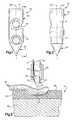
- FIG. 6is a fragmentary schematic illustration depicting the manner in which the suture of FIG. 5 is tensioned with a predetermined force and a connector assembly is utilized to press soft tissue against the bone prior to utilization of the assembly to interconnect sections of the suture;
- FIG. 7is a schematic illustration depicting the manner in which the anchor of FIGS. 1 and 2 is positioned relative to layers of soft body tissue prior to securing of the layers of soft body tissue with a suture connected to the anchor;
- FIG. 8is a schematic sectional view, generally similar to FIG. 7, illustrating the manner in which the anchor and suture cooperate with a retainer to secure the layers of soft body tissue;
- FIG. 9is a schematic sectional view illustrating the manner in which the anchor and suture of FIG. 7 are utilized to interconnect layers of soft body tissue and the manner in which sections of the suture connected with the anchor are interconnected utilizing ultrasonic vibratory energy;
- FIG. 10is a schematic pictorial illustration of an apparatus for use in tensioning a suture with a predetermined tension, applying a predetermined force against a retainer, and connecting the retainer with the suture;
- FIG. 11is a highly schematicized illustration depicting the manner in which the apparatus of FIG. 10 is utilized to tension a suture with a predetermined force, apply a predetermined force against a retainer, and connect the retainer with the suture;
- FIG. 12is a highly schematicized illustration of a second embodiment of the apparatus of FIG. 11 .
- FIGS. 1 and 2One specific anchor 20 constructed in accordance with the present invention is illustrated in FIGS. 1 and 2.
- the anchor 20may be utilized to secure a suture relative to body tissue in a patient's body. However, it is contemplated that, in some situations at least, the anchor 20 may be utilized without a suture.
- the anchor 20is formed of a single piece of bone, specifically, hard compact bone (cortical bone).
- the bone from which the anchor 20 is formedmay be autogenic bone or allogenic bone.
- the anchor 20may be formed of xenogenic bone.
- the anchor 20may be formed of bone obtained from many different sources, it is believed that it may be preferred to form the anchor 20 of freeze dried bone which has been obtained from a human cadaver.
- the bonemay be harvested under clean conditions and treated to achieve sterility.
- the bone forming the anchor 20could be obtained in any one of many different manners under any one of many different conditions.
- the anchor 20may be formed of other materials if desired.
- the anchor 20may be formed of biodegradable or non-biodegradable materials.
- the anchor 20may be formed of polycaperlactone.
- the anchor 20may be formed of metal, such as titanium or stainless steel.
- the anchor 20may be formed of biodegradable or bioerodible copolymers.
- the anchor 20is formed of a single piece of bone and includes a cylindrical body portion 22 and a pointed end portion 24 .
- the pointed end portion 24has a conical configuration.
- the cylindrical body portion 22 and pointed end portion 24have a common longitudinal central axis 28 which extends axially through the anchor 20 .
- the pointed end portion 24has a conical configuration
- the pointed end portioncould have a different configuration if desired.
- the pointed end portioncould be wedge-shaped.
- the pointed end portion 24could have a pyramidal configuration and be formed by the intersection of three, four, or more surfaces. The surfaces could be flat or concave in configuration.
- the anchor 20may be used in association with a suture. If and when the anchor 20 is to be used with a suture, the anchor is provided with a pair of passages 30 and 32 .
- the passages 30 and 32have a cylindrical configuration and extend diametrically through the cylindrical body portion 22 . Central axes of the passages 30 and 32 extend parallel to each other and intersect the central axis 28 of the anchor 20 .
- the passage 30is formed entirely in the body section 22 .
- the passage 32is formed partially in the body section 22 and partially in the pointed end portion 34 .
- the major portion of the passage 32is formed in the body portion 22 .
- a minor portion of the passage 32extends into the pointed end portion 24 .
- two passages 30 and 32extend diametrically through the cylindrical body portion 22 of the anchor.
- This single passagecould be skewed at an acute angle relative to the central axis 28 of the anchor 20 .
- the passagecould extend axially through the anchor.
- the anchor 20could have a different configuration.
- the anchor 20could have the configuration of any one of the anchors illustrated in U.S. Pat. No. 5,527,343 or U.S. Pat. No. 5,534,012.
- the disclosures in the aforementioned U.S. Pat. Nos. 5,534,012 and 5,527,343have been and hereby are incorporated herein in their entirety.
- the anchorIn one specific embodiment of the anchor 20 , intended for use with a suture, the anchor had an overall length of approximately 0.236 inches and a body portion 22 with a diameter of approximately 0.072 inches.
- the passages 30 and 32had diameters of approximately 0.035 inches.
- Another embodiment of the anchor 20had an overall length of approximately 0.354 inches and a body portion 22 with a diameter of approximately 0.119 inches.
- the passages 30 and 32 in the specific anchorhad a diameter of approximately 0.046 inches.
- anchor 20will be formed with dimensions which are different than these specific dimensions.
- an anchor 20 intended for use without a suturemay have a length which is different than the specific lengths previously set forth herein.
- anchors intended for use with soft body tissuemay have dimensions which are different than dimensions of anchors intended for use with hard body tissue.
- the specific embodiment of the anchor 20 described hereinis formed of bone.
- the anchor 20is formed of a single piece of human bone.
- the anchor 20may be formed of other materials if desired.
- the anchor 20may be formed of titanium or titanium alloys.
- the anchor 20may be formed of stainless steel.
- the anchor 20may be formed of any one of many known biodegradable materials.
- the anchor 20may be formed of either biodegradable or nonbiodegradable polymeric materials.
- the anchor 20 of FIGS. 1 and 2may be utilized to secure a suture 36 (FIG. 3) relative to body tissue.
- the suture 36may be formed of a plastic material which is a biopolymer.
- the suture 36is formed of polyglycolide which is commercially available under the trademark DEXON. Polyglycolide is a crystalline material that melts at about 225° Celsius.
- the suture 36is a monofilament suture having a continuous cylindrical outer side surface, it is contemplated that the suture could be formed in a different manner.
- the suture 36could be a cable having an interlaced structure formed by a plurality of filaments or strands which have been twisted, braided, twined, and/or threaded together.
- the suture 36may be formed of a polyglycolide-based copolymer, specifically, 10/90 P-LL/G (10% poly I-lactide and 90% glycolide) which is commercially available under the trademark VICRYL, VICRYL is a crystalline material that melts at about 205° Celsius. VICRYL can be used for either a monofilament or a braided suture.
- the suture 36may have a construction which is similar to the construction of the sutures disclosed in U.S. Pat. No. 5,928,267. The aforementioned U.S. Pat. No. 5,928,267 has been and hereby is incorporated herein in its entirety.
- the strength of the suture 36will vary as a function of the size of the suture. It is contemplated that the specific strength of a particular suture size will vary depending upon the material from which the suture is constructed and the manufacturer of the suture. By consulting a chart, a surgeon can select a suture of a size and strength suitable for a particular use. Thus, a relatively large suture having substantial strength may be selected when body tissue is to be connected with a bone or when portions of a bone are to be interconnected by the suture. On the other hand, a relatively small suture size having a relatively small strength may be selected when delicate body tissue, such as stomach or intestinal tissue is to be interconnected with the suture.
- the anchor 20is utilized with a suture 36 .
- the specific anchor 20 illustrated in FIG. 3is integrally formed as one piece of freeze dried human bone.
- the anchor 20 and suture 30are utilized to hold soft body tissue 40 against movement relative to a portion of a bone 44 in a human patient's body.
- the tissue 40is connective tissue, such as a ligament or tendon. However, the tissue 40 could be other types of tissue if desired.
- the anchor 20is utilized to initiate the formation of an opening in the bone at a location which is free of naturally occurring openings.
- a hard outer surface 48is removed from a compact outer layer 50 of bone by a decortation process.
- the decortation processis performed by abrading the hard outer surface 48 on the compact outer layer 50 of hard cortical bone to expose an imperforate inner area 52 at a location where the anchor 20 and suture 36 are to be utilized to connect the body tissue 40 with the bone 44 .
- the soft body tissue 40is positioned in engagement with the inner area 52 in the manner illustrated schematically in FIG. 3 .
- the decortation processis optional and may be omitted if desired.
- the anchor 20is then moved through the body tissue 40 into the bone 44 . It is believed that it will be preferred to move the anchor 20 into the bone 44 under the influence of an axial force applied against a trailing end portion of the anchor. Since the bone forming the anchor 20 has a relatively high compressive strength, the anchor can be utilized to transmit relatively large forces along the longitudinal central axis 28 (FIG. 1) of the anchor to force the anchor into the bone 44 . However, bone has a relatively low tensile strength and can not transmit large transverse loads.
- the anchor 20when the anchor 20 is moved into the bone 44 under the influence of axial force applied against a trailing end of the anchor, there may be a tendency for the anchor to shear or fail by a lateral buckling or fracture of the anchor rather than by direct compression of the anchor.
- the anchorIn order to support the anchor 20 during movement of the anchor into the bone 44 , the anchor is advantageously inserted into a tubular cylindrical metal sleeve or member 58 (FIG. 3 ).
- a cylindrical pusher member 60is received in the cylindrical sleeve 58 and is utilized to apply an axial force to a circular trailing end surface 62 on the anchor 20 .
- the sleeve and pusher member 58 and 60could have many different configurations and cooperate with each other in many different manners, it may be preferred to utilize a sleeve 58 and pusher member 60 having a construction similar to the construction illustrated in U.S. Pat. No. 5,948,002.
- the disclosure in the aforementioned U.S. Pat. No. 5,948,002is hereby incorporated herein in its entirety by this reference thereto.
- different types of devicescould be utilized to move the anchor 20 into the body tissue 40 and bone 44 if desired.
- the pointed end portion 24 of the anchoris aligned with the body tissue 40 at a location where the anchor is to be moved into the body tissue.
- the sleeve 58is then pressed firmly against the body tissue 40 .
- a substantial spacehas been shown between the inner surface of the sleeve 58 and the cylindrical outer side surface of the anchor 20 in FIG. 3 for purposes of clarity of illustration, it is contemplated that there will be a relatively snug fit of the anchor 20 and pusher member 60 with the inner side surface of the sleeve 58 .
- the anchor 20 and pusher member 60will be freely movable in an axial direction along the sleeve 58 .
- the pusher member 60is then pressed firmly against the trailing surface 62 on the anchor 20 . This force easily moves the pointed leading end portion 24 of the anchor 20 through the soft body tissue 40 into engagement with an imperforate surface area on the compact outer layer 50 of the bone 44 .
- the anchor 20is moved out of the tubular sleeve 58 into the compact outer layer 50 of the bone 44 at a location which is free of naturally occurring openings (FIG. 3 ).
- the pusher memberapplies an axial force against the trailing end surface 62 on the anchor 20 .
- the axial force applied by the pusher member 60moves the pointed leading end portion 24 of the anchor into the compact outer layer 50 of bone.
- the tubular sleeve 58engages the cylindrical outer side surface of the anchor 20 to support the anchor against sidewise loading. This results in the anchor being subjected primarily to compressive force as the anchor is moved into the bone 44 .
- the material of the compact outer layer 50 of the boneis displaced sideways by the leading end portion 24 of the anchor 20 .
- the material of the compact outer layersupports the anchor against transverse loading in much the same manner in which the tubular sleeve 58 supports the anchor. Therefore, the pusher member 60 can apply relatively large axial force to the anchor 20 without failure, that is, without fracture or buckling of the anchor.
- the anchor 20is utilized to initiate formation of an opening in the compact outer layer 50 of the bone 44 at a location which is free of openings. However, if desired, a relatively small pilot opening could be drilled through the compact outer layer 50 of the bone 44 . The anchor 20 would then be utilized to form the small pilot opening into a larger opening through which the anchor can pass.
- the anchor 20is moved through a desired distance into the bone 44 .
- indiciamay be provided on the pusher member 20 .
- the indicia on the pusher member 60cooperates with the sleeve 58 to indicate when the anchor 20 has moved through a desired distance into the bone 44 .
- the application of force against the anchor 20 by the pusher member 36is then interrupted.
- the manner in which the sleeve 58 and pusher member 60 cooperate with the anchor 20is the same as disclosed in U.S. patent application Ser. No. 09/370,865 filed Aug. 9, 1999 by Peter M. Bonutti and entitled “Method of Securing Tissue”.
- the disclosure in the aforementioned U.S. patent application Ser. No. 09/370,865has been and hereby is incorporated herein in its entirety.
- the anchor 20may be utilized, without the suture 36 , to connect the body tissue 40 with the bone 44 .
- the anchor 20will engage both the body tissue 40 and the bone 44 .
- the illustrated embodiment of the anchor 20is intended for use with the suture 36 .
- the pusher member 60is effective to push the anchor 20 through the compact outer layer 50 of hard cortical bone into relatively soft cancellous bone 66 which is enclosed by the hard compact outer layer 50 .
- the pointed leading end portion 24 of the anchor 20enters the cancellous bone 66
- the pointed end portionpushes the cancellous bone 66 aside to form an opening in the cancellous bone.
- the anchormoves into the cancellous bone 66 along a straight path having a longitudinal axis which is coincident with a longitudinal central axis of the sleeve 58 . Therefore, the pointed end portion 24 of the anchor is effective to push aside tissue forming the compact outer layer 50 and the cancellous bone 66 as the anchor moves into the bone 44 .
- the anchorWhen the anchor has moved through a predetermined distance into the cancellous bone 66 , the anchor is pivoted from the orientation illustrated in FIG. 3 to the orientation illustrated in FIG. 4 .
- the orientation of the anchor 20 relative to the bone 44is changed by rotating the anchor through ninety degrees (90°) with a toggling action.
- a section 70 of the suture 36 extending through the anchor passage 32 to a location outside of the boneis tensioned.
- a second section 72which extends through the anchor passage 30 , is relaxed. There is enough friction between the section 70 of the suture and the freeze-dried bone forming the anchor 20 to initiate a pivoting action of the anchor.
- the pusher member 60(FIG. 3) is pressed against a circular rim on the end surface 62 and the tension in the section 70 of the suture is increased.
- the tension in the section 70 of the sutureAs the tension in the section 70 of the suture is increased, the suture tends to slide relative to the material forming the anchor 20 . Therefore, the tension in the section 72 of the suture 36 is increased. However, the tension in the section 70 of the suture will tend to be larger than the tension in the section 72 of the suture.
- the pusher member 60is pressed against the rim of the end surface 62 to maintain the anchor at the desired depth in the cancellous bone 66 .
- the tension in the sections 70 and 72 of the suture 36applies torque to the anchor to rotate the anchor about the location where the anchor engages the pusher member 60 .
- the anchor 20rotates with a toggling action in the manner disclosed in the aforementioned U.S. Pat. Nos. 5,527,343; 5,534,012; and 5,948,002.
- the aforementioned patentshave been and hereby are incorporated herein in their entirety.
- the sections 70 and 72 of the suture 36can be freely moved in the passages 32 and 30 extending through the anchor. This enables the sections 70 and 72 of the suture 36 to be moved relative to each other so that they have the desired length.
- the anchor 20is supported in the cancellous bone 66 in a spaced-apart relationship with the compact outer layer 50 of bone.
- the anchor 20is entirely surrounded by a matrix of the cancellous bone 66 .
- the anchor 20does not touch the compact outer layer 50 of bone.
- Tension forces applied to the anchor 20 by the suture 36are transmitted from the outer side surface of the anchor to the cancellous bone to hold the anchor against movement relative to the bone 44 .
- the suture 36extends through an opening 78 in the compact outer layer 50 of bone into the soft body tissue 40 .
- the sutureextends through the soft body tissue to a location disposed on a side of the soft body tissue opposite from the bone 44 .
- the suture 36extends through the body tissue 40 along the same path which the anchor was moved through the body tissue 40 from the position shown in FIG. 3 to the position shown in FIG. 4 .
- the viscoelastic nature of the soft body tissue 40results in closing of the opening formed in the body tissue 40 by passage of the anchor 20 through the body tissue. However, the sections 70 and 72 of the suture remain in the closed passage through the body tissue 40 along which the anchor 20 previously moved.
- the suture 36may be connected with the soft body tissue in any one of many different ways.
- a retainer 82is connected with the sections 70 and 72 of the suture 36 .
- the sections 70 and 72 of the suture 36could extend straight through the retainer 82 , it is preferred to form a plurality of bends in the suture by wrapping the suture around a portion of the retainer.
- the illustrated retainer 82has a spherical configuration with a cylindrical passage which extends diametrically through the center of the retainer.
- the sections 70 and 72 of the suture 36may be wrapped around the retainer 82 and passed through the passage through the retainer a plurality of times.
- the section 70 of the suture 36extends through the passage in the retainer 82 , around the outer side surface of the retainer and back through the passage again.
- the section 72 of the suture 36also extends through the passage in the retainer 82 , around the outside of the retainer and back through the passage in the retainer.
- the retainer 82could have a different configuration and the suture 36 could be connected with the retainer in a different manner if desired.
- the retainer 82is moved along the sections 70 and 72 of the suture toward the body tissue 40 .
- the retainermoves into engagement with the body tissue.
- the sections 70 and 72 of the suture 36are then tensioned with a predetermined force. This predetermined tension force is transmitted through the retainer 82 to the anchor 20 .
- the retainer 82is pressed downward against the body tissue 40 with a predetermined force.
- the suture retainer 82is connected with the suture 36 .
- the suture retainer 82may be connected with the suture 36 in any one of many different ways. However, the retainer 82 is connected with the suture 36 by plastically deforming the retainer to effect a cold flowing of material of the retainer.
- the cold flowing of the material of the retainer 82results in a collapsing of the passage through the retainer and a flowing of the material of the retainer around the sections 70 and 72 of the suture. This enables the material of the retainer 82 to bond to and obtain a firm grip on the suture 36 .
- the cold flowing of the material of the retainer 82occurs at a temperature which is below the transition temperature of the material forming the retainer.
- the material of the retainer 82bonds to the suture 36 .
- the suture 36is of the cable type and formed by a plurality of interconnected filaments or strands
- the material of the retainer 82flows around and between the strands.
- the material of the retainer 82flows completely around portions of each individual strand and bonds to each individual strand.
- the material of the retainer 82flows around the intertwined suture strands and bonds to them as a group.
- the suture 36is a monofilament, the material of the retainer bonds to only the single strand or filament.
- the retainer 82may be formed of many different materials. However, it is believed that it will be preferred to form the retainer 82 of a biodegradable polymer. Once biodegradable polymer which may be utilized is polycaperlactone. Alternatively, the retainer 82 could be formed of polyethylene oxide terephthalate or polybutylene terephthalate. It is contemplated that other biodegradable or bioerodible copolymers could be utilized. It is believed that it will be preferred to form the suture 36 of the same material as the retainer 82 . Thus, the suture 36 could be formed of any one of the materials previously suggested for forming the retainer 82 .
- the suture retainer 82could be heated to a temperature which is somewhat above the temperature of the body tissue 40 . If desired, heat could be transmitted to the retainer 82 through force application members which effect plastic deformation of the material of the retainer.
- the suture 36has a plurality of twisted strands, flowing of the material of the retainer 82 around the strands of the suture is promoted by heating of the retainer.
- retainer 82could have a different construction if desired.
- the retainer 82could have any one of the constructions disclosed in the aforementioned application Ser. No. 09/523,442.
- the retainer 82could have a different known construction.
- FIGS. 5 and 6In the embodiment of the invention illustrated in FIGS. 1-4, the sections 70 and 72 of the suture 36 extend through the body tissue 40 and are connected with a retainer 82 . In the embodiment of the invention illustrated in FIGS. 5 and 6, one of the sections of the suture extends through the body tissue while the other section of the suture extends around the outside of the body tissue. In the embodiment of the invention illustrated in FIGS. 5 and 6, the retainer is eliminated and the sections of the suture are connected directly to each other. Since the embodiment of the invention illustrated in FIGS. 5 and 6 is similar to the embodiment of the invention illustrated in FIGS. 1-4, similar terminology will be utilized to identify similar components. It should be understood that one or more of the features of the embodiment of the invention illustrated in FIGS. 1-4 may be used with the embodiment of the invention illustrated in FIGS. 5 and 6.
- An anchor 100has the same construction as the anchor 20 of FIGS. 1 and 2.
- the specific anchor 100 of FIGS. 5 and 6is integrally formed as one piece of freeze dried human bone.
- the anchor 100is inserted through soft body tissue in the same manner as was previously described in conjunction with the embodiment of the invention illustrated in FIGS. 3 and 4.
- the anchor 100was moved through a compact outer layer 104 of a bone 106 into cancellous bone 108 in the same manner as was previously described in connection with FIGS. 3 and 4.
- the anchor 100is supported in the cancellous bone 108 in a spaced-apart relationship with the compact outer layer 104 of the bone 106 .
- a suture 110extends through passages in the anchor 100 .
- the suture 110may have either a cable-like or a monofilament construction.
- the suture 110may be a cable having strands formed of any of the materials mentioned in conjunction with the suture 36 of FIGS. 3 and 4.
- the illustrated suture 110is a monofilament having a continuous cylindrical outer side surface.
- Sections 112 and 114 of the suture 110are pulled through the soft body tissue 102 and into the bone 106 as the anchor 100 is inserted into the bone in the manner previously explained in conjunction with the embodiment of the invention illustrated in FIG. 3 .
- a gripperillustrated schematically at 118 in FIG. 5, grips the section 114 of the suture 110 and pulls the section 114 of the suture out of the soft body tissue 102 after the anchor 100 has been positioned in the cancellous bone 108 .
- section 114 of the suture 110is withdrawn from the soft body tissue 102 , the section 112 of the suture remains extending through the soft body tissue in the manner illustrated schematically in FIG. 5 .
- the section 114 of the suture 110is wrapped around the outside of the body tissue and pulled into engagement with the section 112 of the suture.
- the sections 112 and 114 of the suture 110are tensioned with a predetermined force.
- the soft body tissue 102is pressed against the hard compact outer layer 104 of the bone 106 with a predetermined force.
- the two sections 112 and 114 of the suture 110are then connected with each other to hold the soft body tissue 102 in a desired relationship with the bone 106 .
- a force distribution membersuch as a button, may be provided between the suture 110 and the soft body tissue 102 .
- the apparatus 120includes a pair of rotatable wheels or pulleys 122 and 124 .
- the rotatable wheels or pulleys 122 and 124are connected to force measurement transducers which have an output which is proportional to the sideward force applied to the wheels.
- a leftward force(as viewed in FIG. 6) is applied to the rotatable wheel 122 .
- a transducer connected with the wheel 122is effective to provide an output signal which varies as a function of the leftward force applied to the wheel 122 by the suture 112 .
- the sideward force applied against the wheel 122increases.
- the solid state force measuring devicemay be a piezoelectric transducer using a piezoelectric crystal as a sensitive unit. The output from the transducer is transmitted to a controller 128 .
- the wheel 124is connected with a force measuring transducer.
- the force measuring transducer connected with the wheel 124has an output which varies as a function of the force-applied against the wheel 124 by the section 114 of the suture as the suture is tensioned.
- the output from the transducer connected with the wheel 124is also transmitted to the controller 128 .
- clamps 132 and 134are activated to hold the wheels 122 and 124 against rotation and to hold the sections 112 and 114 of the suture 110 against movement relative to the wheels.
- the suture section 112is manually pulled and the wheel 122 rotated until the output from the transducer connected with the wheel indicates that a desired tension is present in the section of the suture.
- the controller 128then activates the clamp 132 to hold both the wheel 122 and the section 112 of the suture against movement. This results in the desired tension being maintained in the section 112 of the suture.
- the clamp 134is activated to clamp the wheel 124 and suture section 114 against movement.
- the controller 128In response to detecting that the desired tension is present in both sections 112 and 114 of the suture 110 , the controller 128 activates a connector assembly 140 (FIG. 6) to press the soft body tissue 102 against the bone 106 with a predetermined force. In response to detecting that the desired tension is present in the sections 112 and 114 of the suture and that the soft body tissue 102 is being pressed against the bone 106 with a desired force, the controller 128 affects operation of the connector assembly 140 to connect the sections 112 and 114 of the suture 110 together.
- the controllerWhen the controller detects that the desired tension is present in the sections 112 and 114 of the suture 110 , the controller activates an actuator (not shown) to press members 142 and 144 in the connector assembly 140 downward against the body tissue 102 with a predetermined force. While the body tissue 102 is being urged downward with a predetermined force and while a desired tension is being maintained in the sections 112 and 114 of the suture 110 , the connector assembly 140 is operated to interconnect the sections 112 and 114 of the suture.
- the sections 112 and 114 of the suturemay be interconnected with a retainer having the same construction as the retainer 82 of FIG. 4 . Alternatively, the sections 112 and 114 of the suture may be bonded together. Regardless of how the suture sections are interconnected, a force distribution member may be provided.
- the member 142functions as an anvil and the member 144 functions as a horn to press the two sections 112 and 114 of the suture against each other and at the same time to transmit ultrasonic vibratory energy to at least one of the two sections of the suture.
- the anvil 142is pressed against one side of the suture sections 112 and 114 .
- the horn 144is pressed against the opposite side of the suture sections 112 and 114 .
- the specific force with which the horn and anvil 144 and 142 are pressed against opposite sides of the suture sections 112 and 114will depend upon the composition of the suture sections and the desired extent of deformation of the suture sections. When at least one, and probably both of the suture sections 112 and 114 have been heat softened by ultrasonic vibratory energy, the material of the suture sections 112 and 114 is pliable. The material of the suture sections 112 and 114 then is plastically deformed by the force applied against the-suture sections by the anvil 142 and horn 144 .
- the apparatus for transmitting ultrasonic vibratory energy to the suture sections 112 and 114includes a generator (not shown) which changes standard electrical power into electrical energy at the desired ultrasonic frequency.
- a transducer(not shown) changes the electrical energy into low amplitude mechanical motion or vibration. These vibrations are transmitted to a booster which is used to increase or decrease the amplitude of the vibrations. The vibrations are then transmitted to the horn 144 .
- the ultrasonic vibratory energy transmitted to the suture sections 112 and 114 from the horn 144is converted into heat energy.
- the temperature of the material forming the portions of the suture sections 112 and 114 adjacent to the horn 144increases.
- the material of the suture sectionsis heated into the lower end portion of a transition temperature range.
- the material softens and becomes pliableAs the material of the suture sections 112 and 114 is heated into the transition temperature range, the material softens and becomes pliable.
- the material of the suture sections 112 and 114does not melt and retains sufficient strength to enable the desired tension to be transmitted through the suture sections.
- the somewhat softened material of the heated portions of the suture sections 112 and 114are pressed together and bond to each other.
- the materials of the suture sections 112 and 114are chemically compatible so that a molecular bond can be established between the suture sections.
- Like materialsthat is materials having chemical properties which are the same or very similar will usually bond together. However, dissimilar materials may bond if their melt temperatures are reasonably close and they are of like molecular structure. Generally speaking, amorphous polymers are readily bonded to each other.
- the connector assembly 140may have a construction similar to constructions of connector assemblies disclosed in U.S. patent application Ser. No. 09/524,397 filed Mar. 13, 2000 by Peter M. Bonutti et al. and entitled “Method of Using Ultrasonic Vibration to Secure Body Tissue”.
- the disclosure in the aforementioned application Ser. No. 09/524,397has been and hereby is incorporated herein in its entirety.
- the anchorhas been utilized to secure a suture relative to a bone in a human patient's body.
- an anchoris utilized to secure a suture relative to soft body tissue in a human patient's body. Since the embodiment of the invention illustrated in FIGS. 7 and 8 is similar to the embodiment of the invention illustrated in FIGS. 1-6, similar terminology will be utilized to identify similar components.
- tissue securing system 154includes an anchor 158 which is connected with a retainer 160 by a suture 162 .
- the tissue securing systemsmay be positioned a precise distance from an edge portion of the layers of human body tissue in the manner disclosed in the aforementioned U.S. patent application Ser. No. 09/524,397 filed March 13, 2000 by Peter M. Bonutti et al. and entitled “Method of Using Ultrasonic Vibration to Secure Body Tissue”.
- the anchor 158has the same construction as the anchor 20 of FIGS. 1 and 2.
- the anchor 158is integrally formed as one piece of freeze dried human bone.
- the suture 162has the same construction as the suture 36 of FIGS. 3 and 4.
- the suture 162has a cable-like construction with a plurality of interconnected strands formed of the materials previously mentioned in conjunction with the suture 36 .
- the suture 162has a section 166 which extends from a passage 168 (FIG. 7) in the anchor 158 .
- the suture 162has a section 170 which extends from a passage 172 in the anchor 158 .
- a pointed leading end portion 176is positioned in engagement with one of the layers of body tissue.
- a central axis of the anchor 158extends perpendicular to the layer 152 of body tissue.
- the anchor 158is positioned in engagement with an imperforate surface area on the thin layer 152 of body tissue.
- the anchorcould be inserted from the other side of the two layers of body tissue if desired. If this was done, the anchor 158 would initially be positioned in engagement with an imperforate surface area on the thick layer 150 of body tissue.
- a forceis applied against a trailing end of the anchor.
- the force 180is effective to push the hard cortical bone of the anchor 158 through the two layers 152 and 150 of body tissue.
- the force 180initially presses the pointed leading end portion 176 of the anchor 158 against the thin layer 152 of body tissue.
- the anchorinitiates the formation of an opening in the layer 152 of body tissue at a location which is free of openings.
- the pointed leading end portion 176 of the anchordeflects body tissue sideways to initiate formation of an opening in the layer 152 .
- the pointed leading end portion 176 of the anchor 158is effective to form openings in the layers 150 and 152 of body tissue at locations which were previously free of openings.
- the leading end portion 176 of the anchor 158moves into engagement with an imperforate surface area on an upper or outer side of the thin layer 152 of body tissue and initiates the formation of an opening in the body tissue.
- the pointed leading end portion 176initiates the formation of an opening at an imperforate surface area on the lower layer of body tissue.
- the openings formed by the anchor 158 as it moves through the layers 150 and 152 of body tissueis closed behind the anchor due to the viscoelastic nature of the body tissue.
- the anchor 158can be moved through the layers 150 and 152 of body tissue under the influence of force applied against the trailing end of the anchor by an inserter assembly which may include a sleeve and pusher member, corresponding to the sleeve 58 and pusher member 60 of FIG. 3 .
- the inserter assembly for moving the anchor 158may have a construction similar to any one of the constructions disclosed in the previously mentioned U.S. Pat. No. 5,948,002 which has been and hereby is incorporated herein.
- the section 166 of the suture 162is tensioned.
- the anchor 158 and the layers 150 and 152 of body tissueapply sufficient friction against the section 170 of the suture 162 that tensioning the section 166 of the suture is effective to apply a torque to the anchor which rotates it from the orientation illustrated in FIG. 7 to the orientation illustrated in FIG. 8 .
- the central axis of the anchorextends generally parallel to the major side surfaces of the layers 150 and 152 of body tissue.
- the two sections 166 and 170 of the suturecan be tensioned and freely moved relative to the anchor to adjust the relative lengths of the sections 166 and 170 of the suture.
- the retainer 160has a spherical configuration with a cylindrical central passage.
- the retainer 160could have a configuration of any one of the retainers disclosed in the aforementioned U.S. patent application Ser. No. 09/523,442 filed Mar. 10, 2000 by Peter M. Bonutti et al. and entitled “Method and Apparatus for Securing a Suture”.
- the retainer 160could have a configuration corresponding to the configuration of any other known retainer.
- the suture 162When the suture 162 has been positioned relative to the retainer, the suture is tensioned with a predetermined tension force.
- the retainer 160is then moved along the sections 166 and 170 of the suture and pressed against the layers 152 and 150 of body tissue with a predetermined force.
- a force distribution membersuch as a button, could be provided between the retainer 160 and the layer 152 of body tissue.
- Another force distribution membercould be provided between the anchor 158 and the layer 150 of body tissue.
- the retainer 160While the predetermined tension is maintained in the suture 162 and while the retainer 160 is urged toward the body tissue with a predetermined force, the retainer 160 is fixedly connected with the suture 162 .
- the retainer 160may be fixedly connected with the suture by plastically deforming material of the suture retainer with a cold flowing action or by heating the material of the retainer and plastically deforming the material of the retainer while it is heated into a transition temperature range for the material of the retainer. Heating of the material of the retainer may be accomplished by applying ultrasonic vibratory energy against the suture retainer in the manner disclosed in the aforementioned application Ser. No. 09/524,397, filed Mar. 13, 2000 by Peter M. Bonutti et al.
- the retainer 160may be connected with the suture 162 in any one of the ways disclosed in the aforementioned U.S. patent application Ser. No. 09/523,442 filed Mar. 10, 2000 by Peter M. Bonutti et al. and entitled “Method and Apparatus for Securing a Suture”.
- a tissue securing system 154is utilized to interconnect layers 150 and 152 of body tissue.
- a retainer 160is associated with a suture to apply a predetermined force against the layers 150 and 152 of body tissue and to maintain a predetermined tension in the sections 166 and 170 of the suture.
- the suture retaineris omitted and the sections of the suture are connected directly to each other. Since the embodiment of the invention illustrated in FIG. 9 is similar to the embodiments of the invention illustrated in FIGS. 1-8, similar terminology will be utilized to identify similar components. It should be understood that one or more of the features of the embodiments of the invention illustrated in FIGS. 1-8 could be utilized in association with the embodiment of the invention illustrated in FIG. 9 .
- tissue layers 180 and 182are disposed in linear apposition with each other.
- a tissue securing system 184is utilized to interconnect the layers 180 and 182 of soft human body tissue.
- the tissue securing system 184includes an anchor 188 and a suture 190 .
- the anchor 188has the same construction as the anchor 20 of FIGS. 1 and 2.
- the specific anchor 188 illustrated in FIG. 9is formed as one piece of freeze dried human bone.
- the suture 190has the same construction as the suture 36 of FIGS. 3 and 4.
- the suture 190is connected with the anchor in the same manner as previously described in conjunction with the embodiment of the invention illustrated in FIGS. 7 and 8.
- the suture 190has sections 192 and 194 which extend from passages 196 and 198 through the layers 180 and 182 of body tissue.
- a force distribution member or button 196is provided adjacent to the upper (as viewed in FIG. 9) major side surface of the layer 180 of tissue.
- the force distribution member 198distributes force transmitted from the suture 190 over a relatively large area on the layer 180 of tissue.
- the two sections 192 and 194 of the sutureare tensioned with a predetermined tension force.
- the force distribution member 196is pressed against the layer 180 of body tissue with a predetermined force. While the predetermined tension is maintained in the suture 190 and while the force distribution member 196 is pressed against the layer 180 of tissue with a predetermined force, the two sections 192 and 194 of the suture 190 are bonded to each other by a connector assembly 200 .
- the connector assembly 200may have the same construction as previously described in conjunction with the embodiment of the invention illustrated in FIG. 6 .
- the connector assembly 200may have a construction which is different than the construction of the connector assembly 140 of FIG. 6 .
- the two sections 192 and 194 of the suture 190may be tensioned with a predetermined force by an apparatus having the same construction as the apparatus 120 of FIG. 6 .
- the two sections 192 and 194 of the suture 190may be tensioned in a different manner if desired.
- the suture sections 192 and 194could be manually tightened without using the apparatus 120 of FIG. 6 .
- the connector assembly 200includes an anvil 202 which is pressed against one side of the sections 192 and 194 of the suture 190 .
- a horn 204is pressed against the opposite sides of the sections 192 and 194 of the suture 190 . While the horn and anvil 202 and 204 are being pressed against opposite sides of the sections 192 and 194 of the suture 190 , ultrasonic vibratory energy is transmitted from the horn 204 to at least one of the sections of the suture.
- the ultrasonic vibratory energy transmitted from the horn 204 to the sections 192 and 194 of the suture 190is effective to heat the material of the sections of the suture into their transition temperature range as the sections of the suture are pressed against each other.
- FIGS. 10 and 11An apparatus for use in tensioning the suture and effecting the transmittal of force to body tissue is illustrated in FIGS. 10 and 11 .
- FIGS. 10 and 11An apparatus for use in tensioning the suture and effecting the transmittal of force to body tissue is illustrated in FIGS. 10 and 11 .
- FIGS. 10 and 11An apparatus for use in tensioning the suture and effecting the transmittal of force to body tissue is illustrated in FIGS. 10 and 11 .
- the apparatus of FIGS. 10 and 11is advantageously used with a retainer, the apparatus may be used without a retainer if desired.
- FIGS. 10 and 11is similar to the embodiments of the invention illustrated in FIGS. 1-9, similar terminology will be utilized to identify similar components. It should be understood that one or more features of the embodiments of the invention illustrated in FIGS. 1-9 may be used with the embodiment of the invention illustrated in FIGS. 10 and 11.
- An apparatus 220(FIGS. 10 and 11) is utilized to secure a suture 222 (FIG. 11) relative to body tissue.
- the suture 222may have the same construction as the suture 36 if FIGS. 3 and 4.
- the specific suture 222is a cable with a plurality of interconnected strands or filaments. However, the suture 222 could be formed of a single strand if desired.
- the body tissueincludes soft body tissue 224 and bone 226 .
- the bone 226includes a compact outer layer 228 which encloses cancellous bone 230 .
- the apparatus 220has been illustrated in FIG. 11 in association with soft body tissue 224 and bone 226 , it is contemplated that the apparatus 220 could be utilized in association with just soft tissue in the manner illustrated in FIG. 8 . Alternatively, the apparatus 220 could be utilized with just hard tissue. Thus, the apparatus 220 could be utilized with fragments of a bone or with separate bones if desired.
- the apparatus 220includes a housing 234 (FIG. 10 ). In FIG. 11, the housing has been omitted and the apparatus enclosed by the housing has been illustrated schematically.
- the apparatus 220(FIG. 11) includes a suture tensioning assembly 238 .
- the suture tensioning assembly 238is operable to tension the suture 222 with a predetermined tension force.
- the apparatus 220also includes a force application assembly 242 (FIG. 11 ).
- the force application assembly 242is operable to apply a predetermined force to a retainer 244 to urge the retainer toward the soft body tissue 224 and bone 226 .
- the suture tensioning assembly 238is disposed in the upper end portion of the housing 234 (FIG. 10) and the force application assembly 242 is disposed in the lower end portion of the housing.
- a connector assembly 248(FIG. 11) is provided in the lower end portion of the housing 234 adjacent to the force application assembly 242 .
- the connector assembly 248is operable to connect the retainer 244 with the suture 242 .
- a predetermined tension forceis applied to the suture 242 by the suture tensioning assembly 238 and a predetermined force is transmitted from the force application assembly 242 through the retainer 244 to the soft body tissue 224 and bone 226 when the connector assembly 248 is operated to connect the retainer with the suture.
- a trimmer assembly 252(FIG. 11) is provided in the housing 234 (FIG. 10 ).
- the trimmer assembly 252is disposed between the suture tensioning assembly 238 and force application assembly 242 .
- the trimmer assembly 252is operable to sever the suture 222 after the connector assembly 248 has connected the retainer 244 with the suture and while the predetermined tension is present in the suture and a predetermined force is being transmitted from the retainer through the body tissue 224 .
- Operation of the connector assembly 248 and trimmer assembly 252is controlled by a microprocessor or controller 256 .
- the controller 256detects when the predetermined tension is present in the suture 222 and when the predetermined force is transmitted through the retainer 244 to the soft body tissue 224 and bone 226 .
- the controller 256initiates operation of the connector assembly 248 to connect the retainer 244 with the suture 222 .
- the controller 256effects operation of the trimmer assembly 252 to sever the suture 222 .
- the controller 256(FIG. 11) effects operation of the connector assembly 248 when both a predetermined tension is present in the suture 222 and a predetermined force is being transmitted through the retainer to the body tissue 224 and bone 226 .
- the apparatus 220could be constructed in such a manner as to have the controller 256 effect operation of the connector assembly 248 in response to only detection of a predetermined tension in the suture 222 .
- the controller 256could effect operation of the connector assembly 248 in response to only detection of transmission of a predetermined force to the retainer 244 and body tissue 224 .
- the controller 256(FIG. 11) is spaced from the housing 234 (FIG. 10 ).
- the controller 256is connected with the apparatus disposed in the housing through a cable 258 .
- the controller 256could, if desired, be mounted on or in the housing 234 .
- the suture 222is connected with an anchor 260 which is embedded in the cancellous bone 230 in a spaced apart relationship with the compact outer layer 228 of the bone 226 .
- the anchor 260has the same construction as the anchor 20 of FIGS. 1 and 2.
- Sections 262 and 264 of the suture 222extend from passages in the anchor through the compact outer layer 228 of the bone 226 and the soft body tissue 224 to the retainer 244 .
- the sections 262 and 264 of the suture 222extend through the force transmission assembly 242 and trimmer assembly 252 to the suture tensioning assembly 238 .
- suture 222is connected with the anchor 260 in the embodiment of the invention illustrated in FIG. 11, it is contemplated that the suture 222 could be connected with body tissue in a manner other than through the use of the anchor 260 .
- suture 222could be connected with body tissue in any one of the ways disclosed in the aforementioned U.S. patent application Ser. No. 09/523,442 filed Mar. 10, 2000 by Peter M. Bonutti et al. and entitled “Method and Apparatus for Securing a Suture”.
- the suture 222could be connected with either hard or soft body tissue in other known ways if desired.
- the suturecould be connected with body tissue in any one of the ways disclosed in the aforementioned U.S. Pat. No. 5,928,267. It is contemplated that the apparatus 220 will be utilized in association with sutures which are connected with many different types of body tissue in many different ways.
- the suture tensioning assembly 238is operable to tension the suture 222 with at least a predetermined tension force.
- the suture tensioning assembly 238includes a circular upper member 270 having an opening through which the sections 262 and 264 of the suture 222 extend.
- the upper member 270is movable downward relative to the housing 234 from the uppermost position illustrated in FIG. 10 . Although the upper member 270 can move downward from the position shown in FIGS. 10 and 11, the upper member can not move upward from the position shown in FIGS. 10 and 11.
- the sections 262 and 264 of the suture 222are fixedly secured to the upper member 270 .
- a pin 272extends upward from the upper member 270 .
- the sections 262 and 264 of the suture 222are tied to the pin 272 .
- sections 262 and 264 of the suture 222could be connected with the upper member 270 in a different manner if desired.
- the sections 262 and 264 of the suturecould be locked in a V-shaped slot formed in the upper member 270 .
- a gripper assemblycould be provided on the upper member 270 to grip the sections 262 and 264 of the suture.
- a circular lower member 276 in the suture tensioning assembly 238(FIG. 11) is connected with the upper member 270 by a plurality of springs which have been illustrated schematically at 278 in FIG. 11 .
- the lower member 276is movable relative to the housing 234 .
- the lower member 276can only move upward from the position shown in FIGS. 10 and 11. When the lower member 276 moves upward, the springs 278 are compressed.
- a pair of manually engageable handles 282 and 284(FIG. 10) are fixedly connected with diametrically opposite sides of the cylindrical lower member 276 .
- the handles 282 and 284extend through slots in the housing 234 and are readily engaged by fingers on the hand of a surgeon during use of the apparatus 220 .
- the handles 282 and 284can be manually moved upward (as viewed in FIG. 10) to move the lower member 276 upward relative to the housing 234 .
- the handles 282 and 284are engagable with lower ends of the slots in the housing to block downward movement of the lower member 276 from the position shown in FIG. 11 .
- the sections 262 and 264 of the sutureare first tied off at the pin 272 .
- an initial tension forceis transmitted from the suture to the upper member 270 .
- This initial tension forcemoves the upper member 270 downward and slightly compress the springs 278 .
- the handles 282 and 284are pressed against lower ends of the slots in the housing 234 to resist the initial tension force.
- Fingers on one hand of the surgeonthen apply an upwardly directed force against the handles 282 and 284 .
- This upwardly directed forceis applied against the springs 278 (FIG. 10) by the lower member 276 .
- the upwardly directed forceis transmitted through the springs 278 to the upper member 270 and the sections 262 and 264 of the suture 222 .
- the springs 278are compressed and the tension in the sections 262 and 264 of the suture 222 is increased.
- a movable contact 282moves upward toward a second contact 284 .
- the movable contact 282is fixedly connected to the lower member 276 .
- the second contact 284is fixedly connected to the upper member 270 .
- the movable contact 282moves upward into engagement with the second or upper contact 284 when the springs 278 have been compressed to a predetermined extent by movement of the lower member 276 toward the upper member 270 .
- a predetermined forceis transmitted from the lower member 276 to the upper member 270 . This predetermined force is transmitted to the sections 262 and 264 of the suture through the pin 272 connected with the upper member 270 .
- a circuitis completed between conductors 286 and 288 connected with the movable contact 282 and second contact 284 .
- the conductors 286 and 288are connected with the controller 256 . This enables the controller 256 to detect when the movable contact 282 engages the second or upper contact 284 and when the predetermined tension is present in the suture 222 .
- the controller 256provides a visual and/or an audible signal to indicate to the surgeon that the predetermined tension force is being applied to the sections 262 and 264 of the suture 222 .
- the force application assembly 242is operable to apply at least a predetermined force to the retainer 244 .
- This predetermined forceurges the retainer toward the soft body tissue 224 and bone 226 .
- the force transmitted from the retainer 244 to the soft body tissue 224is effective to compress the soft body tissue against the bone 226 .
- the force application assembly 242includes a circular lower member 294 which is located at the lower end of the housing 234 (FIG. 10 ).
- the lower member 294is movable upward from its lowermost position shown in FIG. 11 .
- the lower member 294is engageable with the retainer 244 .
- the lower member 294may have a lower (as viewed FIG. 11) side surface which is shaped to provide a recess in which the upper portion of the retainer 244 is received.
- the lower member 294is illustrated in FIG. 11 as having a flat circular lower side surface, the lower member 294 could have a concave surface with an arc of curvature which corresponds to the arc of curvature of the spherical retainer 244 .
- An upper member 298 in the force application assembly 242has a generally cylindrical configuration and is disposed in a coaxial relationship with the lower member 294 .
- the upper member 298is fixedly connected with the housing 234 (FIG. 10 ).
- the lower member 294is axially movable relative to the housing 234 .
- the lower member 294is connected with the upper member 298 by a plurality of springs which have been illustrated schematically at 302 in FIG. 11 .
- An upper contact 304is fixedly connected with the upper member 298 .
- a lower or movable contact 306is connected with the lower member 294 .
- the upper contact 304is connected with the controller 256 by a conductor 310 .
- the movable contact 306is connected with the controller 256 by a conductor 312 .
- a guide rod 313extends between the lower member 294 in the force application assembly 242 and the upper member 270 in the suture tensioning assembly 238 .
- the guide rodinterconnects the suture tensioning assembly 238 and the force application assembly 242 .
- the guide rodguides relative movement between the upper member 270 and lower member 276 in the suture tensioning assembly 238 and relative movement between the upper member 298 and lower member 294 in the force application assembly 242 .
- a knurled handle portion 314(FIG. 10) of the housing 234 is manually grasped.
- a collar 315may be provided adjacent to the lower end of the handle portion 315 .
- Forceis manually applied to the housing 234 urging the housing downward (as viewed in FIG. 11) toward the retainer 244 .
- an upward forceis being manually applied against the handles 282 and 284 .
- the downward force which is manually applied to the housing 234is transmitted to the upper member 298 (FIG. 11) which is fixedly connected with the housing. This downward force is transmitted from the upper member 298 through the springs 302 to the lower member 294 .
- the lower member 294transmits the force to the retainer 244 which is pressed against the soft body tissue 224 .
- the springs 302As the housing 234 and upper member 298 are manually urged downward toward the retainer 244 , the springs 302 (FIG. 11) are compressed. As the springs 302 are compressed, the upper contact 304 approaches the lower contact 306 . When the springs 302 have been compressed to a predetermined extent, a predetermined force is transmitted from the upper member 298 through the springs 302 and lower member 294 to the retainer 244 and body tissue 224 . As this occurs, upper contact 304 engages the lower contact 306 .
- the connector assembly 248includes a pair of movable members 316 and 318 which are disposed adjacent to diametrically opposite sides of the retainer 244 .
- An actuator 320is connected with the movable member 316 .
- An actuator 322is connected with the movable member 318 .
- the actuators 320 and 322are connected with the controller 256 by conductors 324 and 326 .
- the actuators 320 and 322are operable to press the movable members 316 and 318 against opposite sides of the retainer 244 and to effect plastic deformation of the material of the retainer 244 .
- Force applied against opposite sides of the retainer 244 by the members 316 and 318is effective to cause cold flowing of the material of the retainer at a temperature below a transition temperature range for the material of the retainer.
- the cold flowing of the material of the retainer 244results in a collapsing of a passage in the retainer through which the sections 262 and 264 of the suture extend.
- the material of the retainer 244As the passage through the retainer 244 collapses and the material of the retainer cold flows, the material flows around the sections 262 and 264 of the suture 222 . This enables the material of the retainer 244 to bond to and obtain a firm grip on the suture 222 .
- the sections 262 and 264 of the suture 222extends straight through the passage in the retainer 244 .
- the sections 262 and 264 of the suture 222could be wrapped around the retainer. If this was done, the force applied against the sections of the suture and the retainer 244 would embed the suture turns around the outside of the retainer 244 in the material of the retainer and enhance the grip between the suture 222 and the retainer 244 .
- the retaineris pressed against the upper side surface of the body tissue 224 with a predetermined force.
- a predetermined tensionis maintained in the sections 262 and 264 of the suture 222 .
- the connector assembly 248could be constructed so as to effect heating of the material of the retainer 244 by the application of ultrasonic vibratory energy to the retainer.
- the frictional heat created by the ultrasonic vibratory energy transmitted to the suture retainer 244is effective to heat the material of the suture retainer into a transition temperature range to facilitate collapsing of the passage in the retainer and to facilitate bonding of the material of the retainer with the sections 262 and 264 of the suture 222 .
- the movable member 316could be an anvil which engages one side of the retainer and the movable member 318 could be a horn which applies ultrasonic vibratory energy to the retainer.
- the trimmer assembly 252is operated to sever the sections 262 and 264 of the suture.
- the trimmer assembly 252is operable to sever the sections 262 and 264 of the suture 222 at a location disposed between the suture tensioning assembly 238 and the force application assembly 242 . Since the retainer 244 has been securely connected to the suture before the trimmer assembly 252 is operated, the retainer is effective to maintain the predetermined tension in the sections 262 and 264 of the suture which extend between the retainer and the anchor 260 . In addition, the retainer 244 is effective to apply the predetermined force against the body tissue 224 .
- the trimmer assembly 252includes a pair of cutter assemblies 340 and 342 .
- the cutter assemblies 340 and 342are connected with the controller 256 by conductors 344 and 346 .
- the controller 256initiates operation of the cutter assemblies 340 and 342 in the trimmer assembly 252 to sever the sections 262 and 264 of the suture 222 .
- the suture 222(FIG. 11 ), anchor 260 and retainer 244 are to be utilized to secure the soft body tissue 224 with the bone 226 , the suture 222 is inserted through the passages in the anchor 260 in the manner previously explained in conjunction with the embodiment of the invention illustrated in FIGS. 1-4.
- a pointed end portion 352 of the anchor 260is positioned relative to the soft body tissue 224 while the soft body tissue is in a desired location relative to the bone 226 in the manner illustrated schematically in FIG. 3 .
- An inserter assemblyis then utilized to move the anchor 20 through the body tissue 224 and into the bone 226 .
- the anchoris toggled from an orientation similar to the orientation illustrated in FIG. 3 to the orientation illustrated in FIG. 11 .
- the retainer 244is slid along the sections 262 and 264 of the suture into engagement with the body tissue 224 .
- the suture sections 262 and 264are then positioned in the apparatus 220 (FIG. 10 ).
- a slot 356is formed in the apparatus 220 to facilitate positioning of the sections 262 and 264 of the suture in the apparatus.
- the slot 256extends through the housing to central portions of the suture tensioning assembly 238 (FIG. 11 ), force application assembly 242 , connector assembly 248 , and trimmer assembly 252 .
- a passagecould be provided through the apparatus and the sections 262 and 264 of the suture inserted through the passage.
- the apparatusis moved along the suture 222 into engagement with the retainer 244 . While the apparatus 220 is pressed firmly against the retainer 244 , the sections 262 and 264 of the suture are tied to the pin 272 . At this time, there will be some tension in the sections 262 and 264 of the suture 222 and there will be some force transmitted from the force application assembly 242 to the retainer 244 . However, the tension in the suture and the force transmitted to the retainer will be less than a minimum desired tension and force.
- a surgeonmanually grasps the handle portion 314 (FIG. 10) of the housing 234 with one hand and pushes the housing toward the retainer 244 (FIG. 11 ). As this occurs, the springs 302 in the force application assembly are compressed and the contact 304 moves into engagement with the contact 306 to indicate to the controller that the predetermined force is being transmitted from the apparatus 220 to the retainer 244 .
- the controller 256may provide a visual and/or audible indication to the surgeon that a predetermined force has been transmitted through the retainer 244 to the body tissue 224 .
- the lower contact 282 in the suture tensioning assembly 238is in engagement with the upper contact 284 to provide an indication to the controller that the predetermined tension is present in the suture.
- the controller 256may provide a second visual or audible signal to the surgeon.
- the controller 256effects operation of the connector assembly 248 to securely connect the retainer 244 with the sections 262 and 264 of suture.
- the controller 256effects operation of the trimmer assembly 252 to sever the sections 262 and 264 of the suture. This enables the apparatus 220 to be moved away from the body tissue 224 .
- a suture retainer 244is connected with the sections 262 and 264 of the suture 222 .
- the sections of the sutureare connected to each other. Since the embodiment of the invention illustrated in FIG. 12 is similar to the embodiments of the invention illustrated in FIGS. 1-11, similar terminology will be utilized to identify similar components. It should be understood that one or more features of the embodiments of the invention illustrated in FIGS. 1-11 may be used with the embodiment of the invention illustrated in FIG. 12 .
- the apparatus 420is utilized to secure a suture 422 relative to soft body tissue 424 and a bone 426 .
- the suture 422may have the same construction as the suture 36 of FIGS. 3 and 4.
- the specific suture 422is a monofilament having a continuous cylindrical outer side surface. However, the suture 422 may be formed a plurality of intertwined strands or filaments.
- the bone 426includes a compact outer layer 428 which encloses cancellous bone 430 .
- the suture 422has been illustrated schematically in FIG. 12 as being associated with soft body tissue 424 and a bone 426 , it is contemplated that the suture could be associated with just soft body tissue or with two portions of a bone or two bones. It should be understood that the suture 422 could be associated with body tissue in any desired way.
- the apparatus 420includes a suture tensioning assembly 438 which is operable to tension the suture 422 with a predetermined tension force.
- the apparatus 420also includes a force application assembly 442 which is operable to transmit a predetermined force to the soft tissue 424 and bone 426 .
- the apparatus 420also includes a connector assembly 448 .
- the connector assembly 448is operable to connect sections 462 and 464 of the suture with each other while a predetermined tension force is being transmitted through the sections of the suture and while a predetermined force is being transmitted to the soft tissue 424 and bone 426 .
- the connector assembly 448is operable to connect the two sections 462 and 464 of the suture 422 with each other while the suture tensioning assembly 438 tensions the suture to provide a tension force of at least a predetermined magnitude in the sections 462 and 464 of the suture.
- the connector assembly 448is operable to connect the sections 462 and 464 of the suture 422 together while the force application assembly 442 is operable to transmit at least a predetermined force to the soft tissue 424 and bone 426 .
- a trimmer assembly 452is operable to sever the sections 462 and 464 of the suture 422 while the predetermined tension force is present in the sections of the suture and while the predetermined force is transmitted to the soft tissue 424 .
- a controller 456effects operation of the connector assembly 448 to connect the suture sections 462 and 464 together in response to both detection that at least a predetermined tension force is present in the sections 462 and 462 of the suture and detection that at least a predetermined force is being transmitted to the soft tissue 424 and bone 426 .
- the suture tensioning assembly 438 , force application assembly 442 , connector assembly 448 , and trimmer assembly 452are at least partially enclosed by a housing which corresponds to the housing 234 of FIG. 10 .
- the controller 456is connected with the housing by a suitable cable, corresponding to the cable 258 of FIG. 10 . However, the controller could be mounted in or on the housing for the apparatus 420 if desired.
- suture tensioning assembly 438 of FIG. 12corresponds to the suture tensioning assembly 238 of FIG. 11 .
- force application assembly 442 of FIG. 12corresponds to the force application assembly 242 of FIG. 11 .
- the connector assembly 448 of FIG. 12corresponds to the connector assembly 248 of FIG. 11 .
- the trimmer assembly 452 of FIG. 12corresponds to the trimmer assembly 252 of FIG. 11 .
- the suture tensioning assembly 438(FIG. 12) includes a circular upper member 470 and a circular lower member 472 .
- force transducers 478interconnect the upper and lower members 472 .
- the force transducers 478are connected with the controller 456 by leads 486 and 488 .
- the force transducers 478could have many different constructions, it is contemplated that they may be piezoelectric transducers having a piezoelectric crystal as a sensitive element.
- the piezoelectric crystals in the force transducers 478have outputs which correspond to the magnitude of the force being transmitted from the lower member 422 through the force transducers 478 to the upper member 470 .
- the sections 462 and 464 of the suture 422are secured to a pin 472 extending upward from the upper member 470 . Therefore, force transmitted from the lower member 472 to the upper member 470 is transmitted from the upper member through the pin 472 to the suture sections 462 and 464 .
- the output from the force transducers 478indicates to the controller 456 when a predetermined tension force has been transmitted from the lower member 472 through the force transducers 478 and upper member 470 to the sections 462 and 464 of the suture 422 .
- a pair of handles(not shown), corresponding to the handles 282 and 284 of FIG. 10, are connected with the lower member 472 .
- the handles connected with the lower member 472are manually engageable. Force which is manually applied to the handles is transmitted from the lower member 472 through the force transducers 478 to the upper member 470 .
- the force application assembly 442is operable to transmit a predetermined force to the soft tissue 424 and bone 426 .
- the force application assembly 442includes a cylindrical lower member 494 which extends downward into engagement with a force distribution member 496 which is disposed on the soft tissue 424 .
- the force distribution member or button 496has a generally circular configuration with a pair of passages through which the sections 462 and 464 of the suture 422 extend. If desired, the force distribution member 496 could be eliminated.
- the force application assembly 494also includes a cylindrical upper member 498 .
- the upper member 498is connected with the housing (not shown) which encloses the apparatus 420 and corresponds to the housing 234 of FIG. 10 .
- the upper member 498is connected with the lower member 494 by a plurality of force transducers 502 .
- the force transducers 502are connected with the controller 456 through conductors 510 and 512 .
- the output from the force transducers 502corresponds to the magnitude of the force transmitted from the upper member 498 to the lower member 494 .
- the force transducers 502may have many different constructions, in one specific embodiment of the invention, the force transducers 502 were piezoelectric transducers having a piezoelectric crystal as the sensitive unit. However, it should be understood that the force transducers could have any desired construction as long as they were capable of providing an output to the controller which would indicate when at least a predetermined force is being transmitted from the upper member 498 to the lower member 494 and the soft tissue 424 and bone 426 .
- the connector assembly 448includes movable members 516 and 518 .
- the movable members 516 and 518are connected with actuators 520 and 522 .
- the actuators 520 and 522are connected with the controller 456 by conductors 524 and 526 .
- the movable member 516 and movable member 518extend through slots formed in the lower member 494 .
- the lower member 494has a cylindrical configuration and includes radially extending slots in which the movable members 516 and 518 are received.
- the lower (as viewed in FIG. 12) end portion of the lower member 494is disposed in abutting engagement with the force distribution member 496 and is effective to transmit force to the force distribution member.
- the movable members 516 and 518have been illustrated schematically in FIG. 12 as being spaced from the force distribution member 496 , it should be understood that the movable members engage and slide along the force distribution member.
- the controller 456When the controller 456 receives an output from the transducers 478 indicating that at least a predetermined tension is present in the sections 462 and 464 of the suture 422 and receives an output from the force transducers 502 indicating that at least a predetermined force is being transmitted to the soft tissue 424 and bone 426 , the controller 456 effects operation of the connector assembly 448 to interconnect the sections 462 and 464 of the suture 422 .
- the controller 456effects operation of the actuators 520 and 522 to press the members 516 and 518 against opposite sides of the sections 462 and 464 of the suture 422 . While a predetermined clamping force is being applied against the suture sections 462 and 464 to press them against each other, the controller 456 effects operation of the connector assembly 448 to connect the sections 462 and 464 of the suture 422 to each other.
- the sections 462 and 464 of the suture 422are connected to each other by the application of pressure and ultrasonic vibratory energy to the sections of the suture.
- the movable member 516functions as an anvil and the movable member 518 functions as a horn.
- the movable member or hornis 518 vibrated at a rate in excess of 20 kilohertz.
- the horn 518may be vibrated at any desired frequency within a range of 20 kilohertz to 70 kilohertz, it is believed that it may be desirable to vibrate the horn or movable member 518 at a rate which is close to or greater than 70 kilohertz.
- the horn 518is vibrated for a dwell time which is sufficient to transmit enough ultrasonic vibratory energy to the sections 462 and 464 of the suture to heat a portion of the material of the sections of the suture into a transition temperature range of the material
- the heated and softened material of the sections 462 and 464 of the suture 422are flattened from a cylindrical configuration to form thin layers which are disposed in a side-by-side relationship and have a generally plate-like configuration. As the sections 462 and 464 of the suture are pressed together and flattened, they expand in opposite directions transverse to the central axes of the suture sections.
- a trimmer assembly 452is operated to sever the suture sections 462 and 464 at a location between the suture tensioning assembly 438 and force application assembly 442 .
- the trimmer assembly 452includes cutter assemblies 540 and 542 which are connected with the controller 456 by conductors 544 and 546 .
- the controller 456effects operation of actuators in the cutter assemblies 540 and 542 to sever the suture sections.
- the present inventionrelates to a method and apparatus for use in securing soft tissue 40 , hard tissue 44 , and/or hard and soft tissue in a patient's body.
- the hard tissuemay be any one of the many bones in a patient's body.
- the soft tissuemay be any one of the tissues in a patient's body other than the hard tissue.
- the tissuemay be secured by using a suture 36 .
- the suturemay be connected with an anchor 20 .
- the anchorWhen the anchor 20 is utilized in association with the suture, the anchor may be formed of any one of many different materials including bone or other body tissue, biodegradable materials, or non-biodegradable materials.
- the anchor 20may be formed of two or more different materials.
- a retainer 82may be connected with the suture.
- sections 112 and 114 of the suture 110may be connected with each other.
- an apparatus 120 , 220 or 420may advantageously be provided to tension the suture with a predetermined force.
- the apparatus 220may urge the retainer toward the body tissue with a predetermined force.
- the retainer 244may be connected with the suture 222 in response to detection of at least a predetermined tension in the suture and/or the transmission of a predetermined force to the body tissue 224 .
- the sections 462 , 464 of the suture 422may be interconnected in response to detection of a predetermined tension in the suture and/or detection of the transmission of a predetermined force to the body tissue.
- the anchor 22may be formed of a single piece of bone.
- a pointed end portion 24 of the anchormay have a surface which forms an opening in a bone or other tissue in a patient's body.
- the anchor 22may be moved into the opening formed in the tissue by the pointed leading end portion of the anchor.
- a retainer 82may be connected with the suture.
- sections of the suturemay be directly connected with each other.
Landscapes
- Health & Medical Sciences (AREA)
- Surgery (AREA)
- Life Sciences & Earth Sciences (AREA)
- Heart & Thoracic Surgery (AREA)
- Molecular Biology (AREA)
- Veterinary Medicine (AREA)
- Engineering & Computer Science (AREA)
- Biomedical Technology (AREA)
- Public Health (AREA)
- Medical Informatics (AREA)
- Nuclear Medicine, Radiotherapy & Molecular Imaging (AREA)
- Animal Behavior & Ethology (AREA)
- General Health & Medical Sciences (AREA)
- Orthopedic Medicine & Surgery (AREA)
- Rheumatology (AREA)
- Neurology (AREA)
- Surgical Instruments (AREA)
Abstract
Description
Claims (162)
Priority Applications (9)
| Application Number | Priority Date | Filing Date | Title |
|---|---|---|---|
| US09/556,458US6592609B1 (en) | 1999-08-09 | 2000-05-03 | Method and apparatus for securing tissue |
| US09/789,621US6635073B2 (en) | 2000-05-03 | 2001-02-21 | Method of securing body tissue |
| US10/413,696US7087073B2 (en) | 2000-05-03 | 2003-04-14 | Method of securing body tissue |
| US10/614,352US20040010287A1 (en) | 1999-08-09 | 2003-07-07 | Method and apparatus for securing tissue |
| US11/460,650US20060265009A1 (en) | 2000-05-03 | 2006-07-28 | Method of securing body tissue |
| US11/461,110US8814902B2 (en) | 2000-05-03 | 2006-07-31 | Method of securing body tissue |
| US11/931,823US20080140116A1 (en) | 1999-08-09 | 2007-10-31 | Method and apparatus for securing tissue |
| US11/930,621US20080114399A1 (en) | 2000-05-03 | 2007-10-31 | Method of securing body tissue |
| US14/282,908US20140257380A1 (en) | 1999-08-09 | 2014-05-20 | Method of connecting body tissue to a bone |
Applications Claiming Priority (4)
| Application Number | Priority Date | Filing Date | Title |
|---|---|---|---|
| US09/370,865US6447516B1 (en) | 1999-08-09 | 1999-08-09 | Method of securing tissue |
| US09/523,442US6475230B1 (en) | 1997-08-01 | 2000-03-10 | Method and apparatus for securing a suture |
| US09/524,397US6368343B1 (en) | 2000-03-13 | 2000-03-13 | Method of using ultrasonic vibration to secure body tissue |
| US09/556,458US6592609B1 (en) | 1999-08-09 | 2000-05-03 | Method and apparatus for securing tissue |
Related Parent Applications (3)
| Application Number | Title | Priority Date | Filing Date |
|---|---|---|---|
| US09/370,865Continuation-In-PartUS6447516B1 (en) | 1999-08-09 | 1999-08-09 | Method of securing tissue |
| US09/523,442Continuation-In-PartUS6475230B1 (en) | 1997-08-01 | 2000-03-10 | Method and apparatus for securing a suture |
| US09/524,397Continuation-In-PartUS6368343B1 (en) | 1999-08-09 | 2000-03-13 | Method of using ultrasonic vibration to secure body tissue |
Related Child Applications (2)
| Application Number | Title | Priority Date | Filing Date |
|---|---|---|---|
| US09/789,621Continuation-In-PartUS6635073B2 (en) | 2000-01-14 | 2001-02-21 | Method of securing body tissue |
| US10/614,352ContinuationUS20040010287A1 (en) | 1999-08-09 | 2003-07-07 | Method and apparatus for securing tissue |
Publications (1)
| Publication Number | Publication Date |
|---|---|
| US6592609B1true US6592609B1 (en) | 2003-07-15 |
Family
ID=30119315
Family Applications (4)
| Application Number | Title | Priority Date | Filing Date |
|---|---|---|---|
| US09/556,458Expired - Fee RelatedUS6592609B1 (en) | 1999-08-09 | 2000-05-03 | Method and apparatus for securing tissue |
| US10/614,352AbandonedUS20040010287A1 (en) | 1999-08-09 | 2003-07-07 | Method and apparatus for securing tissue |
| US11/931,823AbandonedUS20080140116A1 (en) | 1999-08-09 | 2007-10-31 | Method and apparatus for securing tissue |
| US14/282,908AbandonedUS20140257380A1 (en) | 1999-08-09 | 2014-05-20 | Method of connecting body tissue to a bone |
Family Applications After (3)
| Application Number | Title | Priority Date | Filing Date |
|---|---|---|---|
| US10/614,352AbandonedUS20040010287A1 (en) | 1999-08-09 | 2003-07-07 | Method and apparatus for securing tissue |
| US11/931,823AbandonedUS20080140116A1 (en) | 1999-08-09 | 2007-10-31 | Method and apparatus for securing tissue |
| US14/282,908AbandonedUS20140257380A1 (en) | 1999-08-09 | 2014-05-20 | Method of connecting body tissue to a bone |
Country Status (1)
| Country | Link |
|---|---|
| US (4) | US6592609B1 (en) |
Cited By (239)
| Publication number | Priority date | Publication date | Assignee | Title |
|---|---|---|---|---|
| US20030225438A1 (en)* | 2000-03-13 | 2003-12-04 | Bonutti Peter M. | Method of using ultrasonic vibration to secure body tissue |
| US20040038180A1 (en)* | 2002-08-23 | 2004-02-26 | Woodwelding Ag | Implant, in particular a dental implant |
| US20040038178A1 (en)* | 2002-08-23 | 2004-02-26 | Woodwelding Ag | Preparation for being fastened on a natural tooth part or tooth and corresponding fastening method |
| US20040133238A1 (en)* | 1999-06-22 | 2004-07-08 | Cerier Jeffrey C. | Tissue fixation devices and methods of fixing tissue |
| US20040260344A1 (en)* | 2003-05-07 | 2004-12-23 | Anpa Medical, Inc. | Suture lock |
| US20050065409A1 (en)* | 2003-09-19 | 2005-03-24 | De La Torre Ralph | Pericardial retractor |
| US20050075636A1 (en)* | 2001-12-17 | 2005-04-07 | Leo Gotzen | Bone anchor |
| US20050119698A1 (en)* | 2000-12-22 | 2005-06-02 | Jonathan Martinek | Suture screw |
| US20050126680A1 (en)* | 1999-06-18 | 2005-06-16 | Woodwelding Ag | Integral joining |
| US6913666B1 (en) | 1997-03-21 | 2005-07-05 | Woodwelding Ag | Process for anchoring connecting elements in a material with pores or cavities and connecting elements therefor |
| US20060030884A1 (en)* | 2002-03-14 | 2006-02-09 | Yeung Jeffrey E | Suture anchor and approximating device |
| US20060106423A1 (en)* | 2004-09-28 | 2006-05-18 | Thomas Weisel | Suture anchor |
| US20060105295A1 (en)* | 2004-02-20 | 2006-05-18 | Woodwelding Ag | Implant that can be implanted in osseous tissue and method for producing said implant corresponding implant |
| US20060122543A1 (en)* | 2003-07-31 | 2006-06-08 | Woodwelding Ag | Method for promoting tissue regeneration on wound surfaces as device and treatment instrument or implant for carrying out method |
| US20060184200A1 (en)* | 2005-02-17 | 2006-08-17 | Jervis James E | Suture retainer with multiple circumferentially spaced attachment points and suture retention method |
| US20060265042A1 (en)* | 2005-05-20 | 2006-11-23 | Exploramed Nc2, Inc. | Devices, systems and methods for retracting, lifting, compressing, supporting or repositioning tissues or anatomical structures |
| US20060276871A1 (en)* | 2005-05-20 | 2006-12-07 | Exploramed Nc2, Inc. | Devices, systems and methods for treating benign prostatic hyperplasia and other conditions |
| US20070005067A1 (en)* | 2005-06-21 | 2007-01-04 | Brian Dross | Arthoscopic method and apparatus for tissue attachment to bone |
| US7189235B2 (en) | 1999-10-20 | 2007-03-13 | Anulex Technologies, Inc. | Spinal disc annulus reconstruction method and spinal disc annulus stent |
| US20070265704A1 (en)* | 2006-04-03 | 2007-11-15 | Woodwelding Ag | Surgical method, kit of parts, and implant |
| US20070270833A1 (en)* | 2006-02-07 | 2007-11-22 | Bonutti Peter M | Methods and devices for trauma welding |
| US20080021484A1 (en)* | 2005-05-20 | 2008-01-24 | Neotract, Inc. | Apparatus and method for manipulating or retracting tissue and anatomical structure |
| US20080033458A1 (en)* | 2005-05-20 | 2008-02-07 | Neotract, Inc. | Multi-actuating trigger anchor delivery system |
| US7335205B2 (en) | 2001-03-02 | 2008-02-26 | Woodwelding Ag | Implants, device and method for joining tissue parts |
| WO2008116203A2 (en) | 2007-03-22 | 2008-09-25 | Marctec, Llc | Methods and devices for intracorporeal bonding or interlocking of implants with thermal energy |
| WO2009029908A1 (en) | 2007-08-30 | 2009-03-05 | Marctec, Llc | Methods and devices for utilizing thermal energy to bond, stake and/or remove implants |
| US20090076546A1 (en)* | 2003-05-07 | 2009-03-19 | Anpa Medical, Inc. | Suture lock |
| US20090088797A1 (en)* | 2007-09-28 | 2009-04-02 | Ethicon, Inc. | Surgical anchor device |
| US7601165B2 (en) | 2006-09-29 | 2009-10-13 | Biomet Sports Medicine, Llc | Method and apparatus for forming a self-locking adjustable suture loop |
| US7608092B1 (en) | 2004-02-20 | 2009-10-27 | Biomet Sports Medicince, LLC | Method and apparatus for performing meniscus repair |
| US7615076B2 (en) | 1999-10-20 | 2009-11-10 | Anulex Technologies, Inc. | Method and apparatus for the treatment of the intervertebral disc annulus |
| US20100016899A1 (en)* | 2008-07-18 | 2010-01-21 | Jeffrey Gelfand | Clavicle fixation |
| US7713277B2 (en) | 1999-06-22 | 2010-05-11 | Ethicon Endo-Surgery, Inc. | Tissue reconfiguration |
| US7736373B2 (en) | 1999-06-22 | 2010-06-15 | Ndo Surical, Inc. | Methods and devices for tissue reconfiguration |
| US7749250B2 (en) | 2006-02-03 | 2010-07-06 | Biomet Sports Medicine, Llc | Soft tissue repair assembly and associated method |
| US7766923B2 (en) | 2005-05-20 | 2010-08-03 | Neotract, Inc. | Integrated handle assembly for anchor delivery system |
| US7776057B2 (en) | 1999-06-22 | 2010-08-17 | Ethicon Endo-Surgery, Inc. | Methods and devices for tissue reconfiguration |
| US7780701B1 (en)* | 2003-08-13 | 2010-08-24 | Biomet Sports Medicine, Llc | Suture anchor |
| US7828850B2 (en) | 1999-10-20 | 2010-11-09 | Anulex Technologies, Inc. | Methods and devices for spinal disc annulus reconstruction and repair |
| US20100312051A1 (en)* | 2008-02-14 | 2010-12-09 | Brown Robert C | Method for treating stress urinary incontinence and symptomatic pelvic relaxation |
| US7854750B2 (en) | 2002-08-27 | 2010-12-21 | P Tech, Llc. | Apparatus and method for securing a suture |
| US7857830B2 (en) | 2006-02-03 | 2010-12-28 | Biomet Sports Medicine, Llc | Soft tissue repair and conduit device |
| US20110054525A1 (en)* | 2009-08-25 | 2011-03-03 | Redline Orthopedic Innovations, Inc. | Suture anchor and method of use |
| US7905903B2 (en) | 2006-02-03 | 2011-03-15 | Biomet Sports Medicine, Llc | Method for tissue fixation |
| US7905904B2 (en) | 2006-02-03 | 2011-03-15 | Biomet Sports Medicine, Llc | Soft tissue repair device and associated methods |
| US7909851B2 (en) | 2006-02-03 | 2011-03-22 | Biomet Sports Medicine, Llc | Soft tissue repair device and associated methods |
| US7922768B2 (en) | 1999-10-20 | 2011-04-12 | Anulex Technologies, Inc. | Spinal disc annulus reconstruction method and deformable spinal disc annulus stent |
| US7935147B2 (en) | 1999-10-20 | 2011-05-03 | Anulex Technologies, Inc. | Method and apparatus for enhanced delivery of treatment device to the intervertebral disc annulus |
| US7951201B2 (en) | 1999-10-20 | 2011-05-31 | Anulex Technologies, Inc. | Method and apparatus for the treatment of the intervertebral disc annulus |
| US7959650B2 (en) | 2006-09-29 | 2011-06-14 | Biomet Sports Medicine, Llc | Adjustable knotless loops |
| US20110190815A1 (en)* | 2008-09-08 | 2011-08-04 | Saliman Justin D | Knotless suture anchors |
| US7996967B2 (en) | 2001-08-31 | 2011-08-16 | Quill Medical, Inc. | System for variable-angle cutting of a suture to create tissue retainers of a desired shape and size |
| US8032996B2 (en) | 2003-05-13 | 2011-10-11 | Quill Medical, Inc. | Apparatus for forming barbs on a suture |
| US8083770B2 (en) | 2002-08-09 | 2011-12-27 | Quill Medical, Inc. | Suture anchor and method |
| US8088130B2 (en) | 2006-02-03 | 2012-01-03 | Biomet Sports Medicine, Llc | Method and apparatus for coupling soft tissue to a bone |
| US8118836B2 (en) | 2004-11-05 | 2012-02-21 | Biomet Sports Medicine, Llc | Method and apparatus for coupling soft tissue to a bone |
| US8128658B2 (en) | 2004-11-05 | 2012-03-06 | Biomet Sports Medicine, Llc | Method and apparatus for coupling soft tissue to bone |
| US8128698B2 (en) | 1999-10-20 | 2012-03-06 | Anulex Technologies, Inc. | Method and apparatus for the treatment of the intervertebral disc annulus |
| US8137382B2 (en) | 2004-11-05 | 2012-03-20 | Biomet Sports Medicine, Llc | Method and apparatus for coupling anatomical features |
| US8163022B2 (en) | 2008-10-14 | 2012-04-24 | Anulex Technologies, Inc. | Method and apparatus for the treatment of the intervertebral disc annulus |
| US8216254B2 (en) | 2005-05-20 | 2012-07-10 | Neotract, Inc. | Anchor delivery system with replaceable cartridge |
| US8246652B2 (en) | 1993-05-03 | 2012-08-21 | Ethicon, Inc. | Suture with a pointed end and an anchor end and with equally spaced yieldable tissue grasping barbs located at successive axial locations |
| US8251998B2 (en) | 2006-08-16 | 2012-08-28 | Biomet Sports Medicine, Llc | Chondral defect repair |
| US8287554B2 (en) | 1999-06-22 | 2012-10-16 | Ethicon Endo-Surgery, Inc. | Method and devices for tissue reconfiguration |
| US8298262B2 (en) | 2006-02-03 | 2012-10-30 | Biomet Sports Medicine, Llc | Method for tissue fixation |
| US8303604B2 (en) | 2004-11-05 | 2012-11-06 | Biomet Sports Medicine, Llc | Soft tissue repair device and method |
| US8317825B2 (en) | 2004-11-09 | 2012-11-27 | Biomet Sports Medicine, Llc | Soft tissue conduit device and method |
| US8333776B2 (en) | 2005-05-20 | 2012-12-18 | Neotract, Inc. | Anchor delivery system |
| US8343227B2 (en) | 2009-05-28 | 2013-01-01 | Biomet Manufacturing Corp. | Knee prosthesis assembly with ligament link |
| US8361113B2 (en) | 2006-02-03 | 2013-01-29 | Biomet Sports Medicine, Llc | Method and apparatus for coupling soft tissue to a bone |
| US8394113B2 (en) | 2005-05-20 | 2013-03-12 | Neotract, Inc. | Coiled anchor device |
| US20130096611A1 (en)* | 2011-09-22 | 2013-04-18 | Derek C. Sullivan | Tensionable knotless anchors with splice and methods of tissue repair |
| US8425535B2 (en) | 2005-05-20 | 2013-04-23 | Neotract, Inc. | Multi-actuating trigger anchor delivery system |
| US20130116730A1 (en)* | 2011-11-03 | 2013-05-09 | Biomet Sports Medicine, Llc | Method And Apparatus For Stitching Tendons |
| US8460338B2 (en) | 2008-02-25 | 2013-06-11 | Ethicon, Inc. | Self-retainers with supporting structures on a suture |
| US8460319B2 (en) | 2010-01-11 | 2013-06-11 | Anulex Technologies, Inc. | Intervertebral disc annulus repair system and method |
| US8491606B2 (en) | 2005-05-20 | 2013-07-23 | Neotract, Inc. | Median lobe retraction apparatus and method |
| US8496657B2 (en) | 2006-02-07 | 2013-07-30 | P Tech, Llc. | Methods for utilizing vibratory energy to weld, stake and/or remove implants |
| US8500818B2 (en) | 2006-09-29 | 2013-08-06 | Biomet Manufacturing, Llc | Knee prosthesis assembly with ligament link |
| US8506597B2 (en) | 2011-10-25 | 2013-08-13 | Biomet Sports Medicine, Llc | Method and apparatus for interosseous membrane reconstruction |
| US8529584B2 (en) | 2005-05-20 | 2013-09-10 | Neotract, Inc. | Median lobe band implant apparatus and method |
| US8556977B2 (en) | 1999-10-20 | 2013-10-15 | Anulex Technologies, Inc. | Tissue anchoring system and method |
| US8562645B2 (en) | 2006-09-29 | 2013-10-22 | Biomet Sports Medicine, Llc | Method and apparatus for forming a self-locking adjustable loop |
| US8562647B2 (en) | 2006-09-29 | 2013-10-22 | Biomet Sports Medicine, Llc | Method and apparatus for securing soft tissue to bone |
| US8574235B2 (en) | 2006-02-03 | 2013-11-05 | Biomet Sports Medicine, Llc | Method for trochanteric reattachment |
| US8597327B2 (en) | 2006-02-03 | 2013-12-03 | Biomet Manufacturing, Llc | Method and apparatus for sternal closure |
| US8603106B2 (en) | 2005-05-20 | 2013-12-10 | Neotract, Inc. | Integrated handle assembly for anchor delivery system |
| US8617185B2 (en) | 2007-02-13 | 2013-12-31 | P Tech, Llc. | Fixation device |
| US8615856B1 (en) | 2008-01-30 | 2013-12-31 | Ethicon, Inc. | Apparatus and method for forming self-retaining sutures |
| US20140005729A1 (en)* | 2012-06-29 | 2014-01-02 | Depuy Mitek, Inc. | Tissue Repair Suture Plates and Methods of Use |
| US8628542B2 (en) | 2005-05-20 | 2014-01-14 | Neotract, Inc. | Median lobe destruction apparatus and method |
| US8641732B1 (en) | 2008-02-26 | 2014-02-04 | Ethicon, Inc. | Self-retaining suture with variable dimension filament and method |
| US8652171B2 (en) | 2006-02-03 | 2014-02-18 | Biomet Sports Medicine, Llc | Method and apparatus for soft tissue fixation |
| US8652172B2 (en) | 2006-02-03 | 2014-02-18 | Biomet Sports Medicine, Llc | Flexible anchors for tissue fixation |
| US8668705B2 (en) | 2005-05-20 | 2014-03-11 | Neotract, Inc. | Latching anchor device |
| US20140074160A1 (en)* | 2012-09-11 | 2014-03-13 | Biomet Sports Medicine, Llc | Flexible Planar Member For Tissue Fixation |
| US8672969B2 (en) | 2006-09-29 | 2014-03-18 | Biomet Sports Medicine, Llc | Fracture fixation device |
| US8721681B2 (en) | 2002-09-30 | 2014-05-13 | Ethicon, Inc. | Barbed suture in combination with surgical needle |
| US8721664B2 (en) | 2004-05-14 | 2014-05-13 | Ethicon, Inc. | Suture methods and devices |
| US8734485B2 (en) | 2002-09-30 | 2014-05-27 | Ethicon, Inc. | Sutures with barbs that overlap and cover projections |
| US8747437B2 (en) | 2001-06-29 | 2014-06-10 | Ethicon, Inc. | Continuous stitch wound closure utilizing one-way suture |
| US8758366B2 (en) | 2007-07-09 | 2014-06-24 | Neotract, Inc. | Multi-actuating trigger anchor delivery system |
| US8771313B2 (en) | 2007-12-19 | 2014-07-08 | Ethicon, Inc. | Self-retaining sutures with heat-contact mediated retainers |
| US8771352B2 (en) | 2011-05-17 | 2014-07-08 | Biomet Sports Medicine, Llc | Method and apparatus for tibial fixation of an ACL graft |
| US8777987B2 (en) | 2007-09-27 | 2014-07-15 | Ethicon, Inc. | Self-retaining sutures including tissue retainers having improved strength |
| US8790356B2 (en) | 2010-06-09 | 2014-07-29 | C.R. Bard, Inc. | Instruments for delivering transfascial sutures, transfascial suture assemblies, and methods of transfascial suturing |
| US8793863B2 (en) | 2007-04-13 | 2014-08-05 | Ethicon, Inc. | Method and apparatus for forming retainers on a suture |
| US8801783B2 (en) | 2006-09-29 | 2014-08-12 | Biomet Sports Medicine, Llc | Prosthetic ligament system for knee joint |
| US20140228880A1 (en)* | 2013-02-11 | 2014-08-14 | Leslie John Bisson | Soft tissue-to-bone suturing and monitoring device |
| US8808329B2 (en) | 1998-02-06 | 2014-08-19 | Bonutti Skeletal Innovations Llc | Apparatus and method for securing a portion of a body |
| US8814902B2 (en) | 2000-05-03 | 2014-08-26 | Bonutti Skeletal Innovations Llc | Method of securing body tissue |
| US8834492B2 (en) | 2005-05-20 | 2014-09-16 | Neotract, Inc. | Continuous indentation lateral lobe apparatus and method |
| US8840645B2 (en) | 2004-11-05 | 2014-09-23 | Biomet Sports Medicine, Llc | Method and apparatus for coupling soft tissue to a bone |
| US8845699B2 (en) | 1999-08-09 | 2014-09-30 | Bonutti Skeletal Innovations Llc | Method of securing tissue |
| US8845687B2 (en) | 1996-08-19 | 2014-09-30 | Bonutti Skeletal Innovations Llc | Anchor for securing a suture |
| US8852216B2 (en) | 2007-03-23 | 2014-10-07 | Ethicon Endo-Surgery, Inc. | Tissue approximation methods |
| US8875607B2 (en) | 2008-01-30 | 2014-11-04 | Ethicon, Inc. | Apparatus and method for forming self-retaining sutures |
| US8876865B2 (en) | 2008-04-15 | 2014-11-04 | Ethicon, Inc. | Self-retaining sutures with bi-directional retainers or uni-directional retainers |
| US8916077B1 (en) | 2007-12-19 | 2014-12-23 | Ethicon, Inc. | Self-retaining sutures with retainers formed from molten material |
| US8932330B2 (en) | 2000-03-13 | 2015-01-13 | P Tech, Llc | Method and device for securing body tissue |
| US8932328B2 (en) | 2008-11-03 | 2015-01-13 | Ethicon, Inc. | Length of self-retaining suture and method and device for using the same |
| US8936621B2 (en) | 2006-02-03 | 2015-01-20 | Biomet Sports Medicine, Llc | Method and apparatus for forming a self-locking adjustable loop |
| US8945152B2 (en) | 2005-05-20 | 2015-02-03 | Neotract, Inc. | Multi-actuating trigger anchor delivery system |
| US8961560B2 (en) | 2008-05-16 | 2015-02-24 | Ethicon, Inc. | Bidirectional self-retaining sutures with laser-marked and/or non-laser marked indicia and methods |
| US8968364B2 (en) | 2006-02-03 | 2015-03-03 | Biomet Sports Medicine, Llc | Method and apparatus for fixation of an ACL graft |
| USRE45426E1 (en) | 1997-05-21 | 2015-03-17 | Ethicon, Inc. | Surgical methods using one-way suture |
| US8998949B2 (en) | 2004-11-09 | 2015-04-07 | Biomet Sports Medicine, Llc | Soft tissue conduit device |
| US9017381B2 (en) | 2007-04-10 | 2015-04-28 | Biomet Sports Medicine, Llc | Adjustable knotless loops |
| US20150127027A1 (en)* | 2013-11-04 | 2015-05-07 | Biomet Sports Medicine, Llc | Tissue Contacting Member |
| US9034001B2 (en) | 2005-05-20 | 2015-05-19 | Neotract, Inc. | Slotted anchor device |
| US9044225B1 (en) | 2007-12-20 | 2015-06-02 | Ethicon, Inc. | Composite self-retaining sutures and method |
| US9060767B2 (en) | 2003-04-30 | 2015-06-23 | P Tech, Llc | Tissue fastener and methods for using same |
| US9078644B2 (en) | 2006-09-29 | 2015-07-14 | Biomet Sports Medicine, Llc | Fracture fixation device |
| US9089323B2 (en) | 2005-02-22 | 2015-07-28 | P Tech, Llc | Device and method for securing body tissue |
| US9125647B2 (en) | 2008-02-21 | 2015-09-08 | Ethicon, Inc. | Method and apparatus for elevating retainers on self-retaining sutures |
| US9138222B2 (en) | 2000-03-13 | 2015-09-22 | P Tech, Llc | Method and device for securing body tissue |
| US9149267B2 (en) | 2006-02-03 | 2015-10-06 | Biomet Sports Medicine, Llc | Method and apparatus for coupling soft tissue to a bone |
| US9149266B2 (en) | 2005-05-20 | 2015-10-06 | Neotract, Inc. | Deforming anchor device |
| US9149281B2 (en) | 2002-03-20 | 2015-10-06 | P Tech, Llc | Robotic system for engaging a fastener with body tissue |
| US9161749B2 (en) | 2011-04-14 | 2015-10-20 | Neotract, Inc. | Method and apparatus for treating sexual dysfunction |
| US9173647B2 (en) | 2004-10-26 | 2015-11-03 | P Tech, Llc | Tissue fixation system |
| US9226828B2 (en) | 2004-10-26 | 2016-01-05 | P Tech, Llc | Devices and methods for stabilizing tissue and implants |
| US9237957B2 (en) | 2011-09-16 | 2016-01-19 | Globus Medical, Inc. | Low profile plate |
| US9248580B2 (en) | 2002-09-30 | 2016-02-02 | Ethicon, Inc. | Barb configurations for barbed sutures |
| US9259217B2 (en) | 2012-01-03 | 2016-02-16 | Biomet Manufacturing, Llc | Suture Button |
| US9271713B2 (en) | 2006-02-03 | 2016-03-01 | Biomet Sports Medicine, Llc | Method and apparatus for tensioning a suture |
| US9271766B2 (en) | 2004-10-26 | 2016-03-01 | P Tech, Llc | Devices and methods for stabilizing tissue and implants |
| US20160058551A1 (en)* | 2000-06-22 | 2016-03-03 | Arthrex, Inc. | Knotless graft fixation assembly |
| US9314241B2 (en) | 2011-11-10 | 2016-04-19 | Biomet Sports Medicine, Llc | Apparatus for coupling soft tissue to a bone |
| US9358127B2 (en) | 2008-09-02 | 2016-06-07 | Globus Medical, Inc. | Intervertebral fusion implant |
| US9364212B2 (en) | 2005-05-20 | 2016-06-14 | Neotract, Inc. | Suture anchoring devices and methods for use |
| US9370350B2 (en) | 2011-11-10 | 2016-06-21 | Biomet Sports Medicine, Llc | Apparatus for coupling soft tissue to a bone |
| US9381013B2 (en) | 2011-11-10 | 2016-07-05 | Biomet Sports Medicine, Llc | Method for coupling soft tissue to a bone |
| US9402738B2 (en) | 2013-02-14 | 2016-08-02 | Globus Medical, Inc. | Devices and methods for correcting vertebral misalignment |
| US9408599B2 (en) | 2006-02-03 | 2016-08-09 | Biomet Sports Medicine, Llc | Method and apparatus for coupling soft tissue to a bone |
| US9439642B2 (en) | 2006-02-07 | 2016-09-13 | P Tech, Llc | Methods and devices for utilizing bondable materials |
| US9463012B2 (en) | 2004-10-26 | 2016-10-11 | P Tech, Llc | Apparatus for guiding and positioning an implant |
| US9504461B2 (en) | 2005-05-20 | 2016-11-29 | Neotract, Inc. | Anchor delivery system |
| US9538998B2 (en) | 2006-02-03 | 2017-01-10 | Biomet Sports Medicine, Llc | Method and apparatus for fracture fixation |
| US9539109B2 (en) | 2011-09-16 | 2017-01-10 | Globus Medical, Inc. | Low profile plate |
| US9549739B2 (en) | 2005-05-20 | 2017-01-24 | Neotract, Inc. | Devices, systems and methods for treating benign prostatic hyperplasia and other conditions |
| US9585765B2 (en) | 2013-02-14 | 2017-03-07 | Globus Medical, Inc | Devices and methods for correcting vertebral misalignment |
| US9615936B2 (en) | 2009-06-04 | 2017-04-11 | Globus Medical, Inc. | Intervertebral fusion implant |
| US9615822B2 (en) | 2014-05-30 | 2017-04-11 | Biomet Sports Medicine, Llc | Insertion tools and method for soft anchor |
| US9655611B2 (en) | 2004-06-02 | 2017-05-23 | Kfx Medical, Llc | System and method for attaching soft tissue to bone |
| US9675341B2 (en) | 2010-11-09 | 2017-06-13 | Ethicon Inc. | Emergency self-retaining sutures and packaging |
| US9681959B2 (en) | 2011-09-16 | 2017-06-20 | Globus Medical, Inc. | Low profile plate |
| US9700291B2 (en) | 2014-06-03 | 2017-07-11 | Biomet Sports Medicine, Llc | Capsule retractor |
| US9737294B2 (en) | 2013-01-28 | 2017-08-22 | Cartiva, Inc. | Method and system for orthopedic repair |
| US9744049B2 (en) | 2007-11-16 | 2017-08-29 | DePuy Synthes Products, Inc. | Low profile intervertebral implant |
| US9757119B2 (en) | 2013-03-08 | 2017-09-12 | Biomet Sports Medicine, Llc | Visual aid for identifying suture limbs arthroscopically |
| US9757113B2 (en) | 2013-07-31 | 2017-09-12 | Medos International Sàrl | Adjustable graft fixation device |
| US9770238B2 (en) | 2001-12-03 | 2017-09-26 | P Tech, Llc | Magnetic positioning apparatus |
| US9801708B2 (en) | 2004-11-05 | 2017-10-31 | Biomet Sports Medicine, Llc | Method and apparatus for coupling soft tissue to a bone |
| US9826972B2 (en) | 2011-10-24 | 2017-11-28 | C.R. Bard, Inc. | Instruments for delivering transfascial sutures, transfascial suture assemblies and methods of transfascial suturing |
| US9848994B2 (en) | 2011-09-16 | 2017-12-26 | Globus Medical, Inc. | Low profile plate |
| US9848992B2 (en) | 2010-12-21 | 2017-12-26 | DePuy Synthes Products, Inc. | Intervertebral implants, systems, and methods of use |
| US9867718B2 (en) | 2014-10-22 | 2018-01-16 | DePuy Synthes Products, Inc. | Intervertebral implants, systems, and methods of use |
| US9888916B2 (en) | 2004-03-09 | 2018-02-13 | P Tech, Llc | Method and device for securing body tissue |
| US9895237B2 (en) | 2010-04-08 | 2018-02-20 | Globus Medical, Inc. | Intervertebral implant |
| US9918826B2 (en) | 2006-09-29 | 2018-03-20 | Biomet Sports Medicine, Llc | Scaffold for spring ligament repair |
| US9918827B2 (en) | 2013-03-14 | 2018-03-20 | Biomet Sports Medicine, Llc | Scaffold for spring ligament repair |
| US9949732B2 (en) | 2005-02-07 | 2018-04-24 | Ivy Sports Medicine, Llc | System and method for all-inside suture fixation for implant attachment and soft tissue repair |
| US9955980B2 (en) | 2015-02-24 | 2018-05-01 | Biomet Sports Medicine, Llc | Anatomic soft tissue repair |
| US9955962B2 (en) | 2010-06-11 | 2018-05-01 | Ethicon, Inc. | Suture delivery tools for endoscopic and robot-assisted surgery and methods |
| US9974643B2 (en) | 2013-03-11 | 2018-05-22 | Medos International Sàrl | Implant having adjustable filament coils |
| US10039543B2 (en) | 2014-08-22 | 2018-08-07 | Biomet Sports Medicine, Llc | Non-sliding soft anchor |
| US10052094B2 (en) | 2013-03-11 | 2018-08-21 | Medos International Sàrl | Implant having adjustable filament coils |
| US10058393B2 (en) | 2015-10-21 | 2018-08-28 | P Tech, Llc | Systems and methods for navigation and visualization |
| US10064740B2 (en) | 2003-02-06 | 2018-09-04 | DePuy Synthes Products, LLC | Intervertebral implant |
| US10076377B2 (en) | 2013-01-05 | 2018-09-18 | P Tech, Llc | Fixation systems and methods |
| US10130353B2 (en) | 2012-06-29 | 2018-11-20 | Neotract, Inc. | Flexible system for delivering an anchor |
| US10136886B2 (en) | 2013-12-20 | 2018-11-27 | Biomet Sports Medicine, Llc | Knotless soft tissue devices and techniques |
| US10179012B2 (en) | 2013-01-28 | 2019-01-15 | Cartiva, Inc. | Systems and methods for orthopedic repair |
| US10188384B2 (en) | 2011-06-06 | 2019-01-29 | Ethicon, Inc. | Methods and devices for soft palate tissue elevation procedures |
| US10195014B2 (en) | 2005-05-20 | 2019-02-05 | Neotract, Inc. | Devices, systems and methods for treating benign prostatic hyperplasia and other conditions |
| US10245155B2 (en) | 2011-09-16 | 2019-04-02 | Globus Medical, Inc. | Low profile plate |
| US10265060B2 (en) | 2015-08-20 | 2019-04-23 | Arthrex, Inc. | Tensionable constructs with multi-limb locking mechanism through single splice and methods of tissue repair |
| US10292801B2 (en) | 2012-03-29 | 2019-05-21 | Neotract, Inc. | System for delivering anchors for treating incontinence |
| EP3488794A1 (en)* | 2007-02-06 | 2019-05-29 | Neotract, Inc. | Integrated handle assembly for anchor delivery system |
| US10335136B2 (en) | 2015-08-20 | 2019-07-02 | Arthrex, Inc. | Tensionable constructs with multi-limb locking mechanism through single splice and methods of tissue repair |
| US10405968B2 (en) | 2013-12-11 | 2019-09-10 | Medos International Sarl | Implant having filament limbs of an adjustable loop disposed in a shuttle suture |
| US10420546B2 (en) | 2010-05-04 | 2019-09-24 | Ethicon, Inc. | Self-retaining systems having laser-cut retainers |
| US10433976B2 (en) | 2008-11-07 | 2019-10-08 | DePuy Synthes Products, Inc. | Zero-profile interbody spacer and coupled plate assembly |
| US10492780B2 (en) | 2011-03-23 | 2019-12-03 | Ethicon, Inc. | Self-retaining variable loop sutures |
| US10492922B2 (en) | 2002-02-19 | 2019-12-03 | DePuy Synthes Products, Inc. | Intervertebral implant |
| US10512548B2 (en) | 2006-02-27 | 2019-12-24 | DePuy Synthes Products, Inc. | Intervertebral implant with fixation geometry |
| US10517587B2 (en) | 2006-02-03 | 2019-12-31 | Biomet Sports Medicine, Llc | Method and apparatus for forming a self-locking adjustable loop |
| US10548590B2 (en) | 2005-02-07 | 2020-02-04 | Ivy Sports Medicine, Llc | System and method for all-inside suture fixation for implant attachment and soft tissue repair |
| US10582957B2 (en) | 2014-09-19 | 2020-03-10 | Crossroads Extremity Systems, Llc | Bone fixation implant and means of fixation |
| US10653409B2 (en) | 2015-12-04 | 2020-05-19 | Crossroads Extremity Systems, Llc | Devices and methods for anchoring tissue |
| US10912551B2 (en) | 2015-03-31 | 2021-02-09 | Biomet Sports Medicine, Llc | Suture anchor with soft anchor of electrospun fibers |
| US10925587B2 (en) | 2005-05-20 | 2021-02-23 | Neotract, Inc. | Anchor delivery system |
| US10932769B2 (en) | 2016-05-26 | 2021-03-02 | Ivy Sports Medicine, Llc | System and method for all-inside suture fixation for implant attachment and soft tissue repair |
| US11007296B2 (en) | 2010-11-03 | 2021-05-18 | Ethicon, Inc. | Drug-eluting self-retaining sutures and methods relating thereto |
| US11246638B2 (en) | 2006-05-03 | 2022-02-15 | P Tech, Llc | Methods and devices for utilizing bondable materials |
| US11253296B2 (en) | 2006-02-07 | 2022-02-22 | P Tech, Llc | Methods and devices for intracorporeal bonding of implants with thermal energy |
| US11259792B2 (en) | 2006-02-03 | 2022-03-01 | Biomet Sports Medicine, Llc | Method and apparatus for coupling anatomical features |
| US11259794B2 (en) | 2006-09-29 | 2022-03-01 | Biomet Sports Medicine, Llc | Method for implanting soft tissue |
| US11278273B2 (en)* | 2017-04-14 | 2022-03-22 | Olympus Corporation | Suture securing instrument |
| US11278331B2 (en) | 2006-02-07 | 2022-03-22 | P Tech Llc | Method and devices for intracorporeal bonding of implants with thermal energy |
| US11298115B2 (en) | 2020-08-03 | 2022-04-12 | Teleflex Life Sciences Limited | Handle and cartridge system for medical interventions |
| US11311287B2 (en) | 2006-02-03 | 2022-04-26 | Biomet Sports Medicine, Llc | Method for tissue fixation |
| US11375995B1 (en) | 2021-04-08 | 2022-07-05 | Integrity Orthopaedics, Inc. | Locking suture construct for tensioned suture to suture stitches in anchor arrays for attaching soft tissue to bone |
| US11375991B1 (en) | 2021-04-08 | 2022-07-05 | Integrity Orthopaedics, Inc. | Tensionable and lockable micro suture anchors and anchor arrays for anatomical attachment of soft tissue to bone |
| US11375992B1 (en) | 2021-04-08 | 2022-07-05 | Integrity Orthopaedics, Inc. | Cartridge device for suture anchor and suture management during implantation of a micro suture anchor array |
| US11382613B1 (en) | 2021-04-08 | 2022-07-12 | Integrity Orthopaedics, Inc. | Methods for transtendinous implantation of knotless micro suture anchors and anchor arrays |
| US11382612B1 (en) | 2021-04-08 | 2022-07-12 | Integrity Orthopaedics, Inc. | Method for creating a tensionable and lockable suture anchor array for anatomical attachment of tissue to bone |
| US11589910B2 (en)* | 2016-07-20 | 2023-02-28 | Leonardo Osti | Tensioning device for tendons |
| US11672520B2 (en) | 2017-12-23 | 2023-06-13 | Teleflex Life Sciences Limited | Expandable tissue engagement apparatus and method |
| US11717417B2 (en) | 2011-09-16 | 2023-08-08 | Globus Medical Inc. | Low profile plate |
| US11730528B2 (en) | 2012-05-30 | 2023-08-22 | Globus Medical, Inc. | Aligning vertebral bodies |
| US12096928B2 (en) | 2009-05-29 | 2024-09-24 | Biomet Sports Medicine, Llc | Method and apparatus for coupling soft tissue to a bone |
| US12226307B2 (en) | 2021-04-08 | 2025-02-18 | Integrity Orthopaedics, Inc. | Individually lockable cinch loop micro suture anchor array for high density anatomical attachment of soft tissue to bone |
| US12245759B2 (en) | 2008-08-22 | 2025-03-11 | Biomet Sports Medicine, Llc | Method and apparatus for coupling soft tissue to bone |
| US12329373B2 (en) | 2011-05-02 | 2025-06-17 | Biomet Sports Medicine, Llc | Method and apparatus for soft tissue fixation |
| US12396839B2 (en) | 2021-04-08 | 2025-08-26 | Integrity Orthopaedics, Inc. | Method and apparatus for creating a seam-like anatomical low creep attachment of soft tissue to bone |
| US12419632B2 (en) | 2008-08-22 | 2025-09-23 | Biomet Sports Medicine, Llc | Method and apparatus for coupling anatomical features |
| US12440301B2 (en) | 2019-10-30 | 2025-10-14 | Teleflex Life Sciences Llc | System for delivery of a fiducial marker |
Families Citing this family (129)
| Publication number | Priority date | Publication date | Assignee | Title |
|---|---|---|---|---|
| US8608797B2 (en) | 2005-03-17 | 2013-12-17 | Valtech Cardio Ltd. | Mitral valve treatment techniques |
| EP1874211B1 (en)* | 2005-04-21 | 2017-05-31 | Boston Scientific Scimed, Inc. | Control devices for energy delivery |
| US8333777B2 (en) | 2005-04-22 | 2012-12-18 | Benvenue Medical, Inc. | Catheter-based tissue remodeling devices and methods |
| US8951285B2 (en) | 2005-07-05 | 2015-02-10 | Mitralign, Inc. | Tissue anchor, anchoring system and methods of using the same |
| US7916023B2 (en) | 2006-01-31 | 2011-03-29 | Zebra Enterprise Solutions Corp. | System and method for tracking assets within a monitored environment |
| US9883943B2 (en) | 2006-12-05 | 2018-02-06 | Valtech Cardio, Ltd. | Implantation of repair devices in the heart |
| US11259924B2 (en) | 2006-12-05 | 2022-03-01 | Valtech Cardio Ltd. | Implantation of repair devices in the heart |
| US11660190B2 (en) | 2007-03-13 | 2023-05-30 | Edwards Lifesciences Corporation | Tissue anchors, systems and methods, and devices |
| SI2142107T1 (en) | 2007-03-30 | 2013-05-31 | Sentreheart, Inc. | Devices and systems for closing the left atrial appendage |
| US8523901B2 (en) | 2007-08-14 | 2013-09-03 | Illuminoss Medical, Inc. | Apparatus and methods for attaching soft tissue to bone |
| US8920463B2 (en) | 2008-02-15 | 2014-12-30 | Rex Medical, L.P. | Vascular hole closure device |
| US20110029013A1 (en) | 2008-02-15 | 2011-02-03 | Mcguckin James F | Vascular Hole Closure Device |
| US8491629B2 (en) | 2008-02-15 | 2013-07-23 | Rex Medical | Vascular hole closure delivery device |
| US8070772B2 (en) | 2008-02-15 | 2011-12-06 | Rex Medical, L.P. | Vascular hole closure device |
| US9226738B2 (en) | 2008-02-15 | 2016-01-05 | Rex Medical, L.P. | Vascular hole closure delivery device |
| US8920462B2 (en) | 2008-02-15 | 2014-12-30 | Rex Medical, L.P. | Vascular hole closure device |
| US8382829B1 (en) | 2008-03-10 | 2013-02-26 | Mitralign, Inc. | Method to reduce mitral regurgitation by cinching the commissure of the mitral valve |
| US8029533B2 (en)* | 2008-04-04 | 2011-10-04 | Accessclosure, Inc. | Apparatus and methods for sealing a vascular puncture |
| US9364206B2 (en) | 2008-04-04 | 2016-06-14 | Access Closure, Inc. | Apparatus and methods for sealing a vascular puncture |
| EP2296744B1 (en) | 2008-06-16 | 2019-07-31 | Valtech Cardio, Ltd. | Annuloplasty devices |
| US8147542B2 (en) | 2008-12-22 | 2012-04-03 | Valtech Cardio, Ltd. | Adjustable repair chords and spool mechanism therefor |
| US8911494B2 (en) | 2009-05-04 | 2014-12-16 | Valtech Cardio, Ltd. | Deployment techniques for annuloplasty ring |
| US9011530B2 (en) | 2008-12-22 | 2015-04-21 | Valtech Cardio, Ltd. | Partially-adjustable annuloplasty structure |
| US8715342B2 (en) | 2009-05-07 | 2014-05-06 | Valtech Cardio, Ltd. | Annuloplasty ring with intra-ring anchoring |
| US8241351B2 (en) | 2008-12-22 | 2012-08-14 | Valtech Cardio, Ltd. | Adjustable partial annuloplasty ring and mechanism therefor |
| WO2010073246A2 (en) | 2008-12-22 | 2010-07-01 | Valtech Cardio, Ltd. | Adjustable annuloplasty devices and adjustment mechanisms therefor |
| US10517719B2 (en) | 2008-12-22 | 2019-12-31 | Valtech Cardio, Ltd. | Implantation of repair devices in the heart |
| US8808368B2 (en)* | 2008-12-22 | 2014-08-19 | Valtech Cardio, Ltd. | Implantation of repair chords in the heart |
| WO2010088561A2 (en) | 2009-01-30 | 2010-08-05 | Kfx Medical Corporation | System and method for attaching soft tissue to bone |
| US8353956B2 (en) | 2009-02-17 | 2013-01-15 | Valtech Cardio, Ltd. | Actively-engageable movement-restriction mechanism for use with an annuloplasty structure |
| AU2010232589B2 (en) | 2009-04-01 | 2014-11-27 | Atricure, Inc. | Tissue ligation devices and controls therefor |
| US9968452B2 (en) | 2009-05-04 | 2018-05-15 | Valtech Cardio, Ltd. | Annuloplasty ring delivery cathethers |
| CA2713309C (en) | 2009-08-20 | 2013-07-02 | Howmedica Osteonics Corp. | Flexible acl instrumentation, kit and method |
| ES3036690T3 (en) | 2009-10-13 | 2025-09-23 | Conmed Corp | System for securing tissue to bone |
| US9180007B2 (en) | 2009-10-29 | 2015-11-10 | Valtech Cardio, Ltd. | Apparatus and method for guide-wire based advancement of an adjustable implant |
| US8690939B2 (en) | 2009-10-29 | 2014-04-08 | Valtech Cardio, Ltd. | Method for guide-wire based advancement of a rotation assembly |
| US9011520B2 (en) | 2009-10-29 | 2015-04-21 | Valtech Cardio, Ltd. | Tissue anchor for annuloplasty device |
| US10098737B2 (en) | 2009-10-29 | 2018-10-16 | Valtech Cardio, Ltd. | Tissue anchor for annuloplasty device |
| WO2011154942A2 (en) | 2010-06-07 | 2011-12-15 | Valtech Cardio, Ltd. | Apparatus and method for guide-wire based advancement of a rotation assembly |
| US8734467B2 (en) | 2009-12-02 | 2014-05-27 | Valtech Cardio, Ltd. | Delivery tool for implantation of spool assembly coupled to a helical anchor |
| US8870950B2 (en) | 2009-12-08 | 2014-10-28 | Mitral Tech Ltd. | Rotation-based anchoring of an implant |
| US8475525B2 (en) | 2010-01-22 | 2013-07-02 | 4Tech Inc. | Tricuspid valve repair using tension |
| US9307980B2 (en) | 2010-01-22 | 2016-04-12 | 4Tech Inc. | Tricuspid valve repair using tension |
| US10058323B2 (en) | 2010-01-22 | 2018-08-28 | 4 Tech Inc. | Tricuspid valve repair using tension |
| US8961596B2 (en)* | 2010-01-22 | 2015-02-24 | 4Tech Inc. | Method and apparatus for tricuspid valve repair using tension |
| US8790394B2 (en) | 2010-05-24 | 2014-07-29 | Valtech Cardio, Ltd. | Adjustable artificial chordeae tendineae with suture loops |
| US11653910B2 (en) | 2010-07-21 | 2023-05-23 | Cardiovalve Ltd. | Helical anchor implantation |
| CN103079481B (en) | 2010-08-17 | 2015-11-25 | 雷迪恩斯医药有限责任公司 | For soft tissue being attached to the method and apparatus on bone |
| US9044313B2 (en) | 2010-10-08 | 2015-06-02 | Kfx Medical Corporation | System and method for securing tissue to bone |
| EP2696780B1 (en) | 2011-04-13 | 2018-08-01 | ConMed Corporation | System for securing tissue to bone |
| ES2671928T3 (en) | 2011-06-08 | 2018-06-11 | Sentreheart, Inc. | Tissue ligation devices and tension devices for them |
| US9198648B2 (en) | 2011-06-20 | 2015-12-01 | Ethicon, Inc. | Method and device for approximating tissue |
| US10792152B2 (en) | 2011-06-23 | 2020-10-06 | Valtech Cardio, Ltd. | Closed band for percutaneous annuloplasty |
| EP3345573B1 (en) | 2011-06-23 | 2020-01-29 | Valtech Cardio, Ltd. | Closure element for use with annuloplasty structure |
| US9694106B2 (en)* | 2011-07-11 | 2017-07-04 | Mimedx Group, Inc. | Synthetic collagen threads for cosmetic uses including skin wrinkle treatments and associated methods |
| EP2734157B1 (en) | 2011-07-21 | 2018-09-05 | 4Tech Inc. | Apparatus for tricuspid valve repair using tension |
| US10813630B2 (en) | 2011-08-09 | 2020-10-27 | Corquest Medical, Inc. | Closure system for atrial wall |
| US10307167B2 (en) | 2012-12-14 | 2019-06-04 | Corquest Medical, Inc. | Assembly and method for left atrial appendage occlusion |
| US10314594B2 (en) | 2012-12-14 | 2019-06-11 | Corquest Medical, Inc. | Assembly and method for left atrial appendage occlusion |
| EP3791797B1 (en) | 2011-10-04 | 2024-11-13 | ConMed Corporation | Dual expansion anchor |
| US8858623B2 (en) | 2011-11-04 | 2014-10-14 | Valtech Cardio, Ltd. | Implant having multiple rotational assemblies |
| EP3656434B1 (en) | 2011-11-08 | 2021-10-20 | Valtech Cardio, Ltd. | Controlled steering functionality for implant-delivery tool |
| US9445803B2 (en) | 2011-11-23 | 2016-09-20 | Howmedica Osteonics Corp. | Filamentary suture anchor |
| EP2881083B1 (en) | 2011-12-12 | 2017-03-22 | David Alon | Heart valve repair device |
| US9808242B2 (en) | 2012-04-06 | 2017-11-07 | Howmedica Osteonics Corp. | Knotless filament anchor for soft tissue repair |
| US8961594B2 (en) | 2012-05-31 | 2015-02-24 | 4Tech Inc. | Heart valve repair system |
| US20140039552A1 (en) | 2012-08-03 | 2014-02-06 | Howmedica Osteonics Corp. | Soft tissue fixation devices and methods |
| US9480475B2 (en) | 2012-08-15 | 2016-11-01 | DePuy Synthes Products, Inc. | Bone plate suture anchor |
| US9517060B2 (en) | 2012-09-27 | 2016-12-13 | Ethicon, Inc. | Method and device for approximating tissue |
| US9216018B2 (en) | 2012-09-29 | 2015-12-22 | Mitralign, Inc. | Plication lock delivery system and method of use thereof |
| EP2911593B1 (en) | 2012-10-23 | 2020-03-25 | Valtech Cardio, Ltd. | Percutaneous tissue anchor techniques |
| WO2014064694A2 (en) | 2012-10-23 | 2014-05-01 | Valtech Cardio, Ltd. | Controlled steering functionality for implant-delivery tool |
| US20140142689A1 (en)* | 2012-11-21 | 2014-05-22 | Didier De Canniere | Device and method of treating heart valve malfunction |
| WO2014087402A1 (en) | 2012-12-06 | 2014-06-12 | Valtech Cardio, Ltd. | Techniques for guide-wire based advancement of a tool |
| CN105007832B (en) | 2013-01-09 | 2018-01-23 | 4科技有限公司 | Organize ancora equipment |
| US20150351906A1 (en) | 2013-01-24 | 2015-12-10 | Mitraltech Ltd. | Ventricularly-anchored prosthetic valves |
| EP2961351B1 (en) | 2013-02-26 | 2018-11-28 | Mitralign, Inc. | Devices for percutaneous tricuspid valve repair |
| US9402620B2 (en) | 2013-03-04 | 2016-08-02 | Howmedica Osteonics Corp. | Knotless filamentary fixation devices, assemblies and systems and methods of assembly and use |
| US9788826B2 (en) | 2013-03-11 | 2017-10-17 | Howmedica Osteonics Corp. | Filamentary fixation device and assembly and method of assembly, manufacture and use |
| US9463013B2 (en) | 2013-03-13 | 2016-10-11 | Stryker Corporation | Adjustable continuous filament structure and method of manufacture and use |
| KR102391275B1 (en) | 2013-03-14 | 2022-04-27 | 케이에프엑스 메디컬, 엘엘씨 | Tissue capturing bone anchor |
| US9907681B2 (en) | 2013-03-14 | 2018-03-06 | 4Tech Inc. | Stent with tether interface |
| US10449333B2 (en) | 2013-03-14 | 2019-10-22 | Valtech Cardio, Ltd. | Guidewire feeder |
| CA2904717C (en) | 2013-03-15 | 2021-05-11 | Malcolm Heaven | System and method for securing tissue to bone |
| CN105283214B (en) | 2013-03-15 | 2018-10-16 | 北京泰德制药股份有限公司 | Translate conduit, system and its application method |
| US10292694B2 (en) | 2013-04-22 | 2019-05-21 | Pivot Medical, Inc. | Method and apparatus for attaching tissue to bone |
| US10070857B2 (en) | 2013-08-31 | 2018-09-11 | Mitralign, Inc. | Devices and methods for locating and implanting tissue anchors at mitral valve commissure |
| WO2015059699A2 (en) | 2013-10-23 | 2015-04-30 | Valtech Cardio, Ltd. | Anchor magazine |
| WO2015063580A2 (en) | 2013-10-30 | 2015-05-07 | 4Tech Inc. | Multiple anchoring-point tension system |
| US10052095B2 (en) | 2013-10-30 | 2018-08-21 | 4Tech Inc. | Multiple anchoring-point tension system |
| US10022114B2 (en) | 2013-10-30 | 2018-07-17 | 4Tech Inc. | Percutaneous tether locking |
| US10610211B2 (en) | 2013-12-12 | 2020-04-07 | Howmedica Osteonics Corp. | Filament engagement system and methods of use |
| US9610162B2 (en) | 2013-12-26 | 2017-04-04 | Valtech Cardio, Ltd. | Implantation of flexible implant |
| WO2015193728A2 (en) | 2014-06-19 | 2015-12-23 | 4Tech Inc. | Cardiac tissue cinching |
| EP3174502B1 (en) | 2014-07-30 | 2022-04-06 | Cardiovalve Ltd | Apparatus for implantation of an articulatable prosthetic valve |
| US9667884B2 (en)* | 2014-09-05 | 2017-05-30 | Lsi Solutions, Inc. | System and method for evaluating surgical knot formation |
| EP3922213A1 (en) | 2014-10-14 | 2021-12-15 | Valtech Cardio, Ltd. | Leaflet-restraining techniques |
| US9986992B2 (en) | 2014-10-28 | 2018-06-05 | Stryker Corporation | Suture anchor and associated methods of use |
| US9907547B2 (en) | 2014-12-02 | 2018-03-06 | 4Tech Inc. | Off-center tissue anchors |
| US10568616B2 (en) | 2014-12-17 | 2020-02-25 | Howmedica Osteonics Corp. | Instruments and methods of soft tissue fixation |
| CN110141399B (en) | 2015-02-05 | 2021-07-27 | 卡迪尔维尔福股份有限公司 | Prosthetic valve with axial sliding frame |
| US20160256269A1 (en) | 2015-03-05 | 2016-09-08 | Mitralign, Inc. | Devices for treating paravalvular leakage and methods use thereof |
| CN107847320B (en) | 2015-04-30 | 2020-03-17 | 瓦尔泰克卡迪欧有限公司 | Valvuloplasty techniques |
| US10828160B2 (en) | 2015-12-30 | 2020-11-10 | Edwards Lifesciences Corporation | System and method for reducing tricuspid regurgitation |
| US10751182B2 (en) | 2015-12-30 | 2020-08-25 | Edwards Lifesciences Corporation | System and method for reshaping right heart |
| US10531866B2 (en) | 2016-02-16 | 2020-01-14 | Cardiovalve Ltd. | Techniques for providing a replacement valve and transseptal communication |
| EP3407800A1 (en)* | 2016-05-16 | 2018-12-05 | Boston Scientific Scimed, Inc. | Endoscopic suture and cinch anastomotic leak repair device |
| US10702274B2 (en) | 2016-05-26 | 2020-07-07 | Edwards Lifesciences Corporation | Method and system for closing left atrial appendage |
| GB201611910D0 (en) | 2016-07-08 | 2016-08-24 | Valtech Cardio Ltd | Adjustable annuloplasty device with alternating peaks and troughs |
| US20190231525A1 (en) | 2016-08-01 | 2019-08-01 | Mitraltech Ltd. | Minimally-invasive delivery systems |
| CA3031187A1 (en) | 2016-08-10 | 2018-02-15 | Cardiovalve Ltd. | Prosthetic valve with concentric frames |
| US11045627B2 (en) | 2017-04-18 | 2021-06-29 | Edwards Lifesciences Corporation | Catheter system with linear actuation control mechanism |
| US11793633B2 (en) | 2017-08-03 | 2023-10-24 | Cardiovalve Ltd. | Prosthetic heart valve |
| US12064347B2 (en) | 2017-08-03 | 2024-08-20 | Cardiovalve Ltd. | Prosthetic heart valve |
| US10835221B2 (en) | 2017-11-02 | 2020-11-17 | Valtech Cardio, Ltd. | Implant-cinching devices and systems |
| US11135062B2 (en) | 2017-11-20 | 2021-10-05 | Valtech Cardio Ltd. | Cinching of dilated heart muscle |
| CN116531147A (en) | 2018-01-24 | 2023-08-04 | 爱德华兹生命科学创新(以色列)有限公司 | Contraction of annuloplasty structures |
| EP4248904A3 (en) | 2018-01-26 | 2023-11-29 | Edwards Lifesciences Innovation (Israel) Ltd. | Techniques for facilitating heart valve tethering and chord replacement |
| USD902405S1 (en) | 2018-02-22 | 2020-11-17 | Stryker Corporation | Self-punching bone anchor inserter |
| EP3820406B1 (en) | 2018-07-12 | 2023-12-20 | Edwards Lifesciences Innovation (Israel) Ltd. | Annuloplasty systems and locking tools therefor |
| US11504105B2 (en) | 2019-01-25 | 2022-11-22 | Rex Medical L.P. | Vascular hole closure device |
| SG11202112651QA (en) | 2019-05-29 | 2021-12-30 | Valtech Cardio Ltd | Tissue anchor handling systems and methods |
| US12364606B2 (en) | 2019-07-23 | 2025-07-22 | Edwards Lifesciences Innovation (Israel) Ltd. | Fluoroscopic visualization of heart valve anatomy |
| JP2022546160A (en) | 2019-08-30 | 2022-11-04 | エドワーズ ライフサイエンシーズ イノベーション (イスラエル) リミテッド | Anchor channel tip |
| EP4034042A1 (en) | 2019-09-25 | 2022-08-03 | Cardiac Implants LLC | Cardiac valve annulus reduction system |
| EP4193934A1 (en) | 2019-10-29 | 2023-06-14 | Edwards Lifesciences Innovation (Israel) Ltd. | Annuloplasty and tissue anchor technologies |
| US12023247B2 (en) | 2020-05-20 | 2024-07-02 | Edwards Lifesciences Corporation | Reducing the diameter of a cardiac valve annulus with independent control over each of the anchors that are launched into the annulus |
| CA3182316A1 (en) | 2020-06-19 | 2021-12-23 | Edwards Lifesciences Innovation (Israel) Ltd. | Self-stopping tissue anchors |
| US12357459B2 (en) | 2020-12-03 | 2025-07-15 | Cardiovalve Ltd. | Transluminal delivery system |
Citations (15)
| Publication number | Priority date | Publication date | Assignee | Title |
|---|---|---|---|---|
| US3513848A (en) | 1967-12-11 | 1970-05-26 | Ultrasonic Systems | Ultrasonic suturing |
| US3657056A (en) | 1967-12-11 | 1972-04-18 | Ultrasonic Systems | Ultrasonic suturing apparatus |
| US4662068A (en) | 1985-11-14 | 1987-05-05 | Eli Polonsky | Suture fusing and cutting apparatus |
| US5527343A (en) | 1993-05-14 | 1996-06-18 | Bonutti; Peter M. | Suture anchor |
| US5534012A (en) | 1993-05-14 | 1996-07-09 | Bonutti; Peter M. | Method and apparatus for anchoring a suture |
| US5626612A (en) | 1993-09-20 | 1997-05-06 | Bartlett; Edwin C. | Apparatus and method for anchoring sutures |
| US5718717A (en)* | 1996-08-19 | 1998-02-17 | Bonutti; Peter M. | Suture anchor |
| US5823994A (en) | 1996-03-15 | 1998-10-20 | Oratec Interventions, Inc. | Method and apparatus for soft tissue fixation |
| US5928267A (en) | 1990-06-28 | 1999-07-27 | Peter M. Bonutti | Interconnecting bone across a fracture |
| US5948002A (en) | 1996-11-15 | 1999-09-07 | Bonutti; Peter M. | Apparatus and method for use in positioning a suture anchor |
| US5964765A (en) | 1998-04-16 | 1999-10-12 | Axya Medical, Inc. | Soft tissue fixation device |
| US5968047A (en) | 1996-04-05 | 1999-10-19 | Reed; Thomas Mills | Fixation devices |
| US5989282A (en) | 1996-03-29 | 1999-11-23 | Bonutti; Peter M. | Suture anchor |
| US5993477A (en) | 1998-06-25 | 1999-11-30 | Ethicon Endo-Surgery, Inc. | Ultrasonic bone anchor |
| US6010525A (en) | 1997-08-01 | 2000-01-04 | Peter M. Bonutti | Method and apparatus for securing a suture |
Family Cites Families (167)
| Publication number | Priority date | Publication date | Assignee | Title |
|---|---|---|---|---|
| FR824389A (en)* | 1935-11-25 | 1938-02-07 | Pump for introducing drugs into the vagina or anus and envelopes containing these drugs | |
| US3204635A (en)* | 1963-03-21 | 1965-09-07 | Voss | Hygienic devices |
| US3347234A (en)* | 1964-08-05 | 1967-10-17 | Joseph A Voss | Hygienic devices |
| BE688399A (en)* | 1966-02-16 | 1967-04-18 | ||
| US3518993A (en)* | 1967-05-01 | 1970-07-07 | American Hospital Supply Corp | Surgical clip applicator |
| US3711347A (en)* | 1968-12-09 | 1973-01-16 | D Wagner | Method of sealing and locking a fastener |
| US3760808A (en)* | 1969-12-01 | 1973-09-25 | K Bleuer | Tampon applicator assembly |
| US3653388A (en)* | 1969-12-04 | 1972-04-04 | Battelle Development Corp | Catheter insertion trocar |
| US3709218A (en)* | 1970-04-24 | 1973-01-09 | W Halloran | Combination intramedullary fixation and external bone compression apparatus |
| US3875652A (en)* | 1973-08-08 | 1975-04-08 | Rca Corp | Method of bonding metals together |
| US3918442A (en)* | 1973-10-10 | 1975-11-11 | Georgy Alexandrovich Nikolaev | Surgical instrument for ultrasonic joining of biological tissue |
| US4023559A (en)* | 1975-01-28 | 1977-05-17 | Smith & Nephew (Australia) Pty. Limited | Sampling catheter device |
| US4199864A (en)* | 1975-12-22 | 1980-04-29 | Arthur Ashman | Endosseous plastic implant method |
| US4089071A (en)* | 1976-09-08 | 1978-05-16 | Kalnberz Viktor Konstantinovic | Material for making bone endoprosthesis and endoprosthesis made of said material |
| US4156574A (en)* | 1978-02-06 | 1979-05-29 | Boden Ogden W | Cord lock with self locking spring feelers |
| US4171544A (en)* | 1978-04-05 | 1979-10-23 | Board Of Regents, For And On Behalf Of The University Of Florida | Bonding of bone to materials presenting a high specific area, porous, silica-rich surface |
| US4235238A (en)* | 1978-05-11 | 1980-11-25 | Olympus Optical Co., Ltd. | Apparatus for suturing coeliac tissues |
| DE2827529C2 (en)* | 1978-06-23 | 1982-09-30 | Battelle-Institut E.V., 6000 Frankfurt | Implantable bone replacement material consisting of a metal core and bioactive, sintered calcium phosphate ceramic particles and a process for its production |
| DE2853289C2 (en)* | 1978-12-09 | 1980-12-18 | B. Braun Melsungen Ag, 3508 Melsungen | Button for surgical use |
| US4547327A (en)* | 1980-12-08 | 1985-10-15 | Medical Biological Sciences, Inc. | Method for producing a porous prosthesis |
| US4501031A (en)* | 1981-01-22 | 1985-02-26 | Zimmer, Inc. | Metal and plastic composite tibial component for knee joint |
| ATE23945T1 (en)* | 1981-07-30 | 1986-12-15 | Ceraver | TITANIUM OR TITANIUM ALLOY PROSTHETIC STEM FOR CEMENTLESS FIXATION IN A LONG BONE. |
| FR2515955B1 (en)* | 1981-11-11 | 1987-11-20 | South African Inventions | SURGICAL IMPLANT |
| US4514125A (en)* | 1982-03-19 | 1985-04-30 | Invocas, Inc. | Fastener improvement including introduction of selected capsule of adhesive into porous basket hung in bore for activation by fastener installation |
| US4741330A (en)* | 1983-05-19 | 1988-05-03 | Hayhurst John O | Method and apparatus for anchoring and manipulating cartilage |
| US4823794A (en)* | 1982-07-12 | 1989-04-25 | Pierce William S | Surgical pledget |
| US4691741A (en)* | 1983-06-01 | 1987-09-08 | General Connectors Corporation | Shroud for aircraft duct |
| US4532926A (en)* | 1983-06-20 | 1985-08-06 | Ethicon, Inc. | Two-piece tissue fastener with ratchet leg staple and sealable latching receiver |
| US4990161A (en)* | 1984-03-16 | 1991-02-05 | Kampner Stanley L | Implant with resorbable stem |
| CH668173A5 (en)* | 1984-05-14 | 1988-12-15 | Synthes Ag | DEVICE FOR FIXING TUBE BONE FRACTURES WITH A BONE MARBLE NAIL AND AT LEAST ONE CROSS-BOLT LOCKING. |
| US4718909A (en)* | 1985-07-16 | 1988-01-12 | Brown Byron L | Method and apparatus for cementing a femoral stem prosthesis within a femoral canal |
| US4645503A (en)* | 1985-08-27 | 1987-02-24 | Orthomatrix Inc. | Moldable bone-implant material |
| US5102417A (en)* | 1985-11-07 | 1992-04-07 | Expandable Grafts Partnership | Expandable intraluminal graft, and method and apparatus for implanting an expandable intraluminal graft |
| US4705040A (en)* | 1985-11-18 | 1987-11-10 | Medi-Tech, Incorporated | Percutaneous fixation of hollow organs |
| US4657460A (en)* | 1986-03-17 | 1987-04-14 | Chrysler Motors Corporation | Self-bonding threaded fasteners and method of curing same |
| US4659268A (en)* | 1986-05-15 | 1987-04-21 | Rockwell International Corporation | Composite blind fasteners |
| US4776738A (en)* | 1986-07-14 | 1988-10-11 | Winston Emanuel A | Fastening device |
| US4921479A (en)* | 1987-10-02 | 1990-05-01 | Joseph Grayzel | Catheter sheath with longitudinal seam |
| DE3734108A1 (en)* | 1987-10-06 | 1989-04-20 | Mecron Med Prod Gmbh | INTERMEDIATE NAIL FOR TREATMENT OF BONE BREAKS |
| US4822224A (en)* | 1987-11-05 | 1989-04-18 | Chrysler Motors Corporation | Harness retainer stud |
| US4901721A (en)* | 1988-08-02 | 1990-02-20 | Hakki Samir I | Suturing device |
| DE3831657A1 (en)* | 1988-09-17 | 1990-03-22 | Boehringer Ingelheim Kg | DEVICE FOR THE OSTEOSYNTHESIS AND METHOD FOR THE PRODUCTION THEREOF |
| US4963151A (en)* | 1988-12-28 | 1990-10-16 | Trustees Of The University Of Pennsylvania | Reinforced bone cement, method of production thereof and reinforcing fiber bundles therefor |
| US5098433A (en)* | 1989-04-12 | 1992-03-24 | Yosef Freedland | Winged compression bolt orthopedic fastener |
| US4994071A (en)* | 1989-05-22 | 1991-02-19 | Cordis Corporation | Bifurcating stent apparatus and method |
| NL8901350A (en)* | 1989-05-29 | 1990-12-17 | Wouter Matthijs Muijs Van De M | CLOSURE ASSEMBLY. |
| US5620461A (en)* | 1989-05-29 | 1997-04-15 | Muijs Van De Moer; Wouter M. | Sealing device |
| US4946468A (en)* | 1989-06-06 | 1990-08-07 | Mitek Surgical Products, Inc. | Suture anchor and suture anchor installation tool |
| US4955910A (en)* | 1989-07-17 | 1990-09-11 | Boehringer Mannheim Corporation | Fixation system for an elongated prosthesis |
| US5158934A (en)* | 1989-09-01 | 1992-10-27 | Genentech, Inc. | Method of inducing bone growth using TGF-β |
| US4932960A (en)* | 1989-09-01 | 1990-06-12 | United States Surgical Corporation | Absorbable surgical fastener |
| US4997445A (en)* | 1989-12-08 | 1991-03-05 | Zimmer, Inc. | Metal-backed prosthetic implant with enhanced bonding of polyethylene portion to metal base |
| IT1238173B (en)* | 1990-01-15 | 1993-07-09 | FOUR-TWO-TWO-TWO-CONVERGENT METAL STITCH SUITABLE FOR CONTEMPORARY SUTURE OF THE SKIN AND SUB-SKIN FABRIC | |
| US5391144A (en)* | 1990-02-02 | 1995-02-21 | Olympus Optical Co., Ltd. | Ultrasonic treatment apparatus |
| US5002563A (en)* | 1990-02-22 | 1991-03-26 | Raychem Corporation | Sutures utilizing shape memory alloys |
| US5064286A (en)* | 1990-05-31 | 1991-11-12 | Wyko Corporation | Optical alignment system utilizing alignment spot produced by image inverter |
| US5078731A (en)* | 1990-06-05 | 1992-01-07 | Hayhurst John O | Suture clip |
| US5163960A (en)* | 1990-06-28 | 1992-11-17 | Bonutti Peter M | Surgical devices assembled using heat bondable materials |
| US5236445A (en)* | 1990-07-02 | 1993-08-17 | American Cyanamid Company | Expandable bone anchor and method of anchoring a suture to a bone |
| US5258016A (en)* | 1990-07-13 | 1993-11-02 | American Cyanamid Company | Suture anchor and driver assembly |
| US5100405A (en)* | 1990-09-07 | 1992-03-31 | Mclaren Alexander C | Locking cap for medical implants |
| US5085661A (en)* | 1990-10-29 | 1992-02-04 | Gerald Moss | Surgical fastener implantation device |
| US5085660A (en)* | 1990-11-19 | 1992-02-04 | Lin Kwan C | Innovative locking plate system |
| US5366480A (en)* | 1990-12-24 | 1994-11-22 | American Cyanamid Company | Synthetic elastomeric buttressing pledget |
| US5156613A (en)* | 1991-02-13 | 1992-10-20 | Interface Biomedical Laboratories Corp. | Collagen welding rod material for use in tissue welding |
| DE4106823C1 (en)* | 1991-03-04 | 1992-06-25 | Liebscher Kunststofftechnik, 8032 Graefelfing, De | |
| US5098436A (en)* | 1991-03-07 | 1992-03-24 | Dow Corning Wright Corporation | Modular guide for shaping of femur to accommodate intercondylar stabilizing housing and patellar track of implant |
| US5720753A (en)* | 1991-03-22 | 1998-02-24 | United States Surgical Corporation | Orthopedic fastener |
| CA2063159C (en)* | 1991-03-22 | 1999-06-15 | Thomas W. Sander | Orthopedic fastener |
| US5192287A (en)* | 1991-04-05 | 1993-03-09 | American Cyanamid Company | Suture knot tying device |
| US5258015A (en)* | 1991-05-03 | 1993-11-02 | American Cyanamid Company | Locking filament caps |
| EP0523926A3 (en)* | 1991-07-15 | 1993-12-01 | Smith & Nephew Richards Inc | Prosthetic implants with bioabsorbable coating |
| US5447503A (en)* | 1991-08-14 | 1995-09-05 | Cordis Corporation | Guiding catheter tip having a tapered tip with an expandable lumen |
| US5179964A (en)* | 1991-08-30 | 1993-01-19 | Cook Melvin S | Surgical stapling method |
| EP0545091B1 (en)* | 1991-11-05 | 1999-07-07 | The Children's Medical Center Corporation | Occluder for repair of cardiac and vascular defects |
| US5171251A (en)* | 1992-03-02 | 1992-12-15 | Ethicon, Inc. | Surgical clip having hole therein and method of anchoring suture |
| US5383883A (en)* | 1992-06-07 | 1995-01-24 | Wilk; Peter J. | Method for ultrasonically applying a surgical device |
| US5290281A (en)* | 1992-06-15 | 1994-03-01 | Medicon Eg | Surgical system |
| US5593625A (en)* | 1992-08-11 | 1997-01-14 | Phenix Biocomposites, Inc. | Biocomposite material and method of making |
| GB9217578D0 (en)* | 1992-08-19 | 1992-09-30 | Surgicarft Ltd | Surgical implants,etc |
| US5254113A (en)* | 1992-08-31 | 1993-10-19 | Wilk Peter J | Anastomosis method |
| US5397311A (en)* | 1992-09-09 | 1995-03-14 | Menlo Care, Inc. | Bloodless splittable introducer |
| CA2100532C (en)* | 1992-09-21 | 2004-04-20 | David T. Green | Device for applying a meniscal staple |
| US5383905A (en)* | 1992-10-09 | 1995-01-24 | United States Surgical Corporation | Suture loop locking device |
| US5282832A (en)* | 1992-10-09 | 1994-02-01 | United States Surgical Corporation | Suture clip |
| US6090072A (en)* | 1992-10-15 | 2000-07-18 | Scimed Life Systems, Inc. | Expandable introducer sheath |
| US5354302A (en)* | 1992-11-06 | 1994-10-11 | Ko Sung Tao | Medical device and method for facilitating intra-tissue visual observation and manipulation of distensible tissues |
| US5403312A (en)* | 1993-07-22 | 1995-04-04 | Ethicon, Inc. | Electrosurgical hemostatic device |
| US6338730B1 (en)* | 1993-02-04 | 2002-01-15 | Peter M. Bonutti | Method of using expandable cannula |
| US5320611A (en)* | 1993-02-04 | 1994-06-14 | Peter M. Bonutti | Expandable cannula having longitudinal wire and method of use |
| US5306301A (en)* | 1993-02-11 | 1994-04-26 | American Cyanamid Company | Graft attachment device and method of using same |
| US5505735A (en)* | 1993-06-10 | 1996-04-09 | Mitek Surgical Products, Inc. | Surgical anchor and method for using the same |
| US5304119A (en)* | 1993-06-24 | 1994-04-19 | Monsanto Company | Instrument for injecting implants through animal hide |
| US5500000A (en)* | 1993-07-01 | 1996-03-19 | United States Surgical Corporation | Soft tissue repair system and method |
| US5591206A (en)* | 1993-09-30 | 1997-01-07 | Moufarr+E,Gra E+Ee Ge; Richard | Method and device for closing wounds |
| US5527342A (en)* | 1993-12-14 | 1996-06-18 | Pietrzak; William S. | Method and apparatus for securing soft tissues, tendons and ligaments to bone |
| US5391173A (en)* | 1994-02-10 | 1995-02-21 | Wilk; Peter J. | Laparoscopic suturing technique and associated device |
| US5466243A (en)* | 1994-02-17 | 1995-11-14 | Arthrex, Inc. | Method and apparatus for installing a suture anchor through a hollow cannulated grasper |
| US5417712A (en)* | 1994-02-17 | 1995-05-23 | Mitek Surgical Products, Inc. | Bone anchor |
| DE4447667C2 (en)* | 1994-02-27 | 2002-10-24 | Rainer Hahn | Ultrasonic handpiece |
| US5453090A (en)* | 1994-03-01 | 1995-09-26 | Cordis Corporation | Method of stent delivery through an elongate softenable sheath |
| US5720747A (en)* | 1994-03-11 | 1998-02-24 | Burke; Dennis W. | Apparatus for crimping a surgical wire |
| US5470337A (en)* | 1994-05-17 | 1995-11-28 | Moss; Gerald | Surgical fastener |
| US5464424A (en)* | 1994-06-27 | 1995-11-07 | O'donnell, Jr.; Francis E. | Laser adjustable suture |
| WO1996009797A1 (en)* | 1994-09-28 | 1996-04-04 | Innovasive Devices, Inc. | Suture tensioning device |
| US5681351A (en)* | 1994-10-21 | 1997-10-28 | Ethicon, Inc. | Suture clip suitable for use on monofilament sutures |
| US5504977A (en)* | 1994-10-24 | 1996-04-09 | Newell Operating Company | Device for releasably holding cords |
| US5601595A (en)* | 1994-10-25 | 1997-02-11 | Scimed Life Systems, Inc. | Remobable thrombus filter |
| US6348056B1 (en)* | 1999-08-06 | 2002-02-19 | Scimed Life Systems, Inc. | Medical retrieval device with releasable retrieval basket |
| US5634926A (en)* | 1995-04-25 | 1997-06-03 | Jobe; Richard P. | Surgical bone fixation apparatus |
| US5569306A (en)* | 1995-06-06 | 1996-10-29 | Thal; Raymond | Knotless suture anchor assembly |
| US5866634A (en)* | 1995-09-25 | 1999-02-02 | Shin-Etsu Chemical Co., Ltd | Biodegradable polymer compositions and shrink films |
| US5725556A (en)* | 1995-12-15 | 1998-03-10 | M & R Medical, Inc. | Suture locking apparatus |
| US5817107A (en)* | 1995-12-28 | 1998-10-06 | Schaller; Guenter | Grasping instrument with a guided-on, attachable modified knot pusher |
| US5741282A (en)* | 1996-01-22 | 1998-04-21 | The Anspach Effort, Inc. | Soft tissue fastener device |
| IL116891A0 (en)* | 1996-01-24 | 1996-05-14 | Ovil Joel | Surgical implement particularly useful for implanting prosthetic valves |
| US5735877A (en)* | 1996-02-28 | 1998-04-07 | Pagedas; Anthony C. | Self locking suture lock |
| US5891166A (en)* | 1996-10-30 | 1999-04-06 | Ethicon, Inc. | Surgical suture having an ultrasonically formed tip, and apparatus and method for making same |
| US6371957B1 (en)* | 1997-01-22 | 2002-04-16 | Synthes (Usa) | Device for connecting a longitudinal bar to a pedicle screw |
| US6475230B1 (en)* | 1997-08-01 | 2002-11-05 | Peter M. Bonutti | Method and apparatus for securing a suture |
| US5893880A (en)* | 1997-08-28 | 1999-04-13 | Axya Medical Inc. | Fused loop filamentous material |
| US6286746B1 (en)* | 1997-08-28 | 2001-09-11 | Axya Medical, Inc. | Fused loop of filamentous material and apparatus for making same |
| US6217591B1 (en)* | 1997-08-28 | 2001-04-17 | Axya Medical, Inc. | Suture fastening device |
| US5984929A (en)* | 1997-08-29 | 1999-11-16 | Target Therapeutics, Inc. | Fast detaching electronically isolated implant |
| US6149669A (en)* | 1997-10-30 | 2000-11-21 | Li Medical Technologies, Inc. | Surgical fastener assembly method of use |
| US6099552A (en)* | 1997-11-12 | 2000-08-08 | Boston Scientific Corporation | Gastrointestinal copression clips |
| US6045551A (en)* | 1998-02-06 | 2000-04-04 | Bonutti; Peter M. | Bone suture |
| US6106545A (en)* | 1998-04-16 | 2000-08-22 | Axya Medical, Inc. | Suture tensioning and fixation device |
| US6409743B1 (en)* | 1998-07-08 | 2002-06-25 | Axya Medical, Inc. | Devices and methods for securing sutures and ligatures without knots |
| US6174324B1 (en)* | 1998-07-13 | 2001-01-16 | Axya Medical, Inc. | Suture guide and fastener |
| US6306159B1 (en)* | 1998-12-23 | 2001-10-23 | Depuy Orthopaedics, Inc. | Meniscal repair device |
| CR5992A (en)* | 1999-03-23 | 1999-06-08 | Luis Orlich Bolmarcich Jose | EXTERNAL UNILATERAL TUTOR FOR FIXATION, COMPRESSION OF FRACTURES OR DIAPHISIARIZATION IN HUMAN OSEO TISSUE |
| US6981983B1 (en)* | 1999-03-31 | 2006-01-03 | Rosenblatt Peter L | System and methods for soft tissue reconstruction |
| DE19916161B4 (en)* | 1999-04-11 | 2008-06-05 | Dürr Dental GmbH & Co. KG | Device for generating high-frequency mechanical oscillations for a dental handpiece |
| US6050998A (en)* | 1999-05-21 | 2000-04-18 | Stephen A. Fletcher | Bone fastener |
| US7018380B2 (en)* | 1999-06-10 | 2006-03-28 | Cole J Dean | Femoral intramedullary rod system |
| CH694058A5 (en)* | 1999-06-18 | 2004-06-30 | Woodwelding Ag | Fabric conclusive Connect. |
| US6488196B1 (en)* | 1999-06-30 | 2002-12-03 | Axya Medical, Inc. | Surgical stapler and method of applying plastic staples to body tissue |
| US6179840B1 (en)* | 1999-07-23 | 2001-01-30 | Ethicon, Inc. | Graft fixation device and method |
| CA2380111A1 (en)* | 1999-08-03 | 2001-02-08 | Smith & Nephew, Inc. | Controlled release implantable devices |
| US6368343B1 (en)* | 2000-03-13 | 2002-04-09 | Peter M. Bonutti | Method of using ultrasonic vibration to secure body tissue |
| US6554852B1 (en)* | 1999-08-25 | 2003-04-29 | Michael A. Oberlander | Multi-anchor suture |
| CN1172634C (en)* | 1999-09-13 | 2004-10-27 | 库尔斯恩蒂斯股份公司 | Bone plating system |
| AU781140B2 (en)* | 1999-11-11 | 2005-05-05 | Linvatec Corporation | Toggle anchor and tool for insertion thereof |
| US6709457B1 (en)* | 1999-11-24 | 2004-03-23 | St. Jude Medical, Inc. | Attachment of suture cuff to prosthetic heart valve |
| US7153312B1 (en)* | 1999-12-02 | 2006-12-26 | Smith & Nephew Inc. | Closure device and method for tissue repair |
| US6702821B2 (en)* | 2000-01-14 | 2004-03-09 | The Bonutti 2003 Trust A | Instrumentation for minimally invasive joint replacement and methods for using same |
| US6635073B2 (en)* | 2000-05-03 | 2003-10-21 | Peter M. Bonutti | Method of securing body tissue |
| US6557426B2 (en)* | 2000-02-01 | 2003-05-06 | Richard L. Reinemann, Jr. | Method and apparatus for testing suture anchors |
| US7329263B2 (en)* | 2000-03-13 | 2008-02-12 | Marctec, Llc | Method and device for securing body tissue |
| US6551344B2 (en)* | 2000-04-26 | 2003-04-22 | Ev3 Inc. | Septal defect occluder |
| DE10021122C1 (en)* | 2000-04-29 | 2001-11-08 | Aesculap Ag & Co Kg | Thread anchor system for connecting tissue parts and instrument for inserting an anchor implant |
| US7001411B1 (en)* | 2000-09-25 | 2006-02-21 | Dean John C | Soft tissue cleat |
| US6527774B2 (en)* | 2000-11-08 | 2003-03-04 | The Cleveland Clinic Foundation | Apparatus for attaching fractured sections of bone |
| US6503259B2 (en)* | 2000-12-27 | 2003-01-07 | Ethicon, Inc. | Expandable anastomotic device |
| ATE338516T1 (en)* | 2001-03-02 | 2006-09-15 | Woodwelding Ag | IMPLANTS AND DEVICE FOR CONNECTING TISSUE PARTS |
| US6916321B2 (en)* | 2001-09-28 | 2005-07-12 | Ethicon, Inc. | Self-tapping resorbable two-piece bone screw |
| US6719765B2 (en)* | 2001-12-03 | 2004-04-13 | Bonutti 2003 Trust-A | Magnetic suturing system and method |
| US6955540B2 (en)* | 2002-08-23 | 2005-10-18 | Woodwelding Ag | Preparation for being fastened on a natural tooth part or tooth and corresponding fastening method |
| US7008226B2 (en)* | 2002-08-23 | 2006-03-07 | Woodwelding Ag | Implant, in particular a dental implant |
| EP1601297B1 (en)* | 2003-03-07 | 2013-07-17 | Synthes GmbH | Locking screw for an intramedullary nail |
| EP1765426A4 (en)* | 2004-05-12 | 2011-07-27 | Medivas Llc | Wound healing polymer compositions and methods for use thereof |
| US7179259B1 (en)* | 2004-06-04 | 2007-02-20 | Biomet Manufacturing Corp. | Instrument assembly for lateral implant |
| US8852195B2 (en)* | 2004-07-09 | 2014-10-07 | Zimmer, Inc. | Guide templates for surgical implants and related methods |
| US20060015101A1 (en)* | 2004-07-15 | 2006-01-19 | Wright Medical Technology, Inc. | Intramedullary fixation assembly and devices and methods for installing the same |
| US8496657B2 (en)* | 2006-02-07 | 2013-07-30 | P Tech, Llc. | Methods for utilizing vibratory energy to weld, stake and/or remove implants |
| US7967820B2 (en)* | 2006-02-07 | 2011-06-28 | P Tech, Llc. | Methods and devices for trauma welding |
- 2000
- 2000-05-03USUS09/556,458patent/US6592609B1/ennot_activeExpired - Fee Related
- 2003
- 2003-07-07USUS10/614,352patent/US20040010287A1/ennot_activeAbandoned
- 2007
- 2007-10-31USUS11/931,823patent/US20080140116A1/ennot_activeAbandoned
- 2014
- 2014-05-20USUS14/282,908patent/US20140257380A1/ennot_activeAbandoned
Patent Citations (15)
| Publication number | Priority date | Publication date | Assignee | Title |
|---|---|---|---|---|
| US3657056A (en) | 1967-12-11 | 1972-04-18 | Ultrasonic Systems | Ultrasonic suturing apparatus |
| US3513848A (en) | 1967-12-11 | 1970-05-26 | Ultrasonic Systems | Ultrasonic suturing |
| US4662068A (en) | 1985-11-14 | 1987-05-05 | Eli Polonsky | Suture fusing and cutting apparatus |
| US5928267A (en) | 1990-06-28 | 1999-07-27 | Peter M. Bonutti | Interconnecting bone across a fracture |
| US5527343A (en) | 1993-05-14 | 1996-06-18 | Bonutti; Peter M. | Suture anchor |
| US5534012A (en) | 1993-05-14 | 1996-07-09 | Bonutti; Peter M. | Method and apparatus for anchoring a suture |
| US5626612A (en) | 1993-09-20 | 1997-05-06 | Bartlett; Edwin C. | Apparatus and method for anchoring sutures |
| US5823994A (en) | 1996-03-15 | 1998-10-20 | Oratec Interventions, Inc. | Method and apparatus for soft tissue fixation |
| US5989282A (en) | 1996-03-29 | 1999-11-23 | Bonutti; Peter M. | Suture anchor |
| US5968047A (en) | 1996-04-05 | 1999-10-19 | Reed; Thomas Mills | Fixation devices |
| US5718717A (en)* | 1996-08-19 | 1998-02-17 | Bonutti; Peter M. | Suture anchor |
| US5948002A (en) | 1996-11-15 | 1999-09-07 | Bonutti; Peter M. | Apparatus and method for use in positioning a suture anchor |
| US6010525A (en) | 1997-08-01 | 2000-01-04 | Peter M. Bonutti | Method and apparatus for securing a suture |
| US5964765A (en) | 1998-04-16 | 1999-10-12 | Axya Medical, Inc. | Soft tissue fixation device |
| US5993477A (en) | 1998-06-25 | 1999-11-30 | Ethicon Endo-Surgery, Inc. | Ultrasonic bone anchor |
Non-Patent Citations (3)
| Title |
|---|
| Article entitled "The Search for the; Holy Grail: a Century of Anterior Cruciate Ligament Reconstruction", R. John Naranja, Jr., MD, Jeffrey R. Kuhlman, MD, and Joseph S. Torg, MD, Published by the American Journal of Orthopaedics, Nov. 1997, pp. 743-752. |
| Article under heading the Technical Note, entitled "Meniscus Replacement with Bone Anchors: A Surgical Technique", by Walter R. Shelton, M.D. and Andrea D. Dukes, B.S., published by Arthroscopy: The Journal of Arthroscopic and Related Surgery, vol. 10, No. 3, 1994, pp. 324-327. |
| Article under the heading Technical Note, entitled "Femoral Bone Plug Recession in Endoscopic Anterior Cruciate Ligament Reconstruction", By David E. Taylor, M.D., F.R.A.C.S., Gregory C. R. Keene, M.D., F.R.A.C.S., published by Arthroscopy: The Journal of Arthroscopic and Related Surgery, vol. 12, No. 4 (Aug.), 1996: 513-515. |
Cited By (624)
| Publication number | Priority date | Publication date | Assignee | Title |
|---|---|---|---|---|
| US8246652B2 (en) | 1993-05-03 | 2012-08-21 | Ethicon, Inc. | Suture with a pointed end and an anchor end and with equally spaced yieldable tissue grasping barbs located at successive axial locations |
| US8845687B2 (en) | 1996-08-19 | 2014-09-30 | Bonutti Skeletal Innovations Llc | Anchor for securing a suture |
| US6913666B1 (en) | 1997-03-21 | 2005-07-05 | Woodwelding Ag | Process for anchoring connecting elements in a material with pores or cavities and connecting elements therefor |
| USRE45426E1 (en) | 1997-05-21 | 2015-03-17 | Ethicon, Inc. | Surgical methods using one-way suture |
| US8808329B2 (en) | 1998-02-06 | 2014-08-19 | Bonutti Skeletal Innovations Llc | Apparatus and method for securing a portion of a body |
| US20070062628A1 (en)* | 1999-06-18 | 2007-03-22 | Woodwelding Ag | Integral joining |
| US7815409B2 (en) | 1999-06-18 | 2010-10-19 | Woodwelding Ag | Integral joining |
| US7160405B2 (en) | 1999-06-18 | 2007-01-09 | Woodwelding Ag | Integral joining |
| US20050126680A1 (en)* | 1999-06-18 | 2005-06-16 | Woodwelding Ag | Integral joining |
| US7736373B2 (en) | 1999-06-22 | 2010-06-15 | Ndo Surical, Inc. | Methods and devices for tissue reconfiguration |
| US8277468B2 (en) | 1999-06-22 | 2012-10-02 | Ethicon Endo-Surgery, Inc. | Tissue reconfiguration |
| US8287554B2 (en) | 1999-06-22 | 2012-10-16 | Ethicon Endo-Surgery, Inc. | Method and devices for tissue reconfiguration |
| US7776057B2 (en) | 1999-06-22 | 2010-08-17 | Ethicon Endo-Surgery, Inc. | Methods and devices for tissue reconfiguration |
| US20040133238A1 (en)* | 1999-06-22 | 2004-07-08 | Cerier Jeffrey C. | Tissue fixation devices and methods of fixing tissue |
| US8057494B2 (en) | 1999-06-22 | 2011-11-15 | Ethicon Endo-Surgery, Inc. | Methods and devices for tissue reconfiguration |
| US7846180B2 (en)* | 1999-06-22 | 2010-12-07 | Ethicon Endo-Surgery, Inc. | Tissue fixation devices and methods of fixing tissue |
| US7857823B2 (en) | 1999-06-22 | 2010-12-28 | Ethicon Endo-Surgery, Inc. | Tissue reconfiguration |
| US7896893B2 (en) | 1999-06-22 | 2011-03-01 | Ethicon Endo-Surgery, Inc. | Methods and devices for tissue reconfiguration |
| US7722633B2 (en) | 1999-06-22 | 2010-05-25 | Ethicon Endo-Surgery, Inc. | Tissue reconfiguration |
| US7713277B2 (en) | 1999-06-22 | 2010-05-11 | Ethicon Endo-Surgery, Inc. | Tissue reconfiguration |
| US8845699B2 (en) | 1999-08-09 | 2014-09-30 | Bonutti Skeletal Innovations Llc | Method of securing tissue |
| US8034112B2 (en) | 1999-10-20 | 2011-10-11 | Anulex Technologies, Inc. | Spinal disc annulus reconstruction method and spinal disc annulus stent |
| US8048160B2 (en) | 1999-10-20 | 2011-11-01 | Anulex Technologies, Inc. | Intervertebral disc annulus stent |
| US7189235B2 (en) | 1999-10-20 | 2007-03-13 | Anulex Technologies, Inc. | Spinal disc annulus reconstruction method and spinal disc annulus stent |
| US7985257B2 (en) | 1999-10-20 | 2011-07-26 | Anulex Technologies, Inc. | Methods and devices for spinal disc annulus reconstruction and repair |
| US7935147B2 (en) | 1999-10-20 | 2011-05-03 | Anulex Technologies, Inc. | Method and apparatus for enhanced delivery of treatment device to the intervertebral disc annulus |
| US7922768B2 (en) | 1999-10-20 | 2011-04-12 | Anulex Technologies, Inc. | Spinal disc annulus reconstruction method and deformable spinal disc annulus stent |
| US9095442B2 (en) | 1999-10-20 | 2015-08-04 | Krt Investors, Inc. | Method and apparatus for the treatment of the intervertebral disc annulus |
| US7909879B2 (en) | 1999-10-20 | 2011-03-22 | Anulex Technologies, Inc. | Intervertebral disc annulus stent |
| US9114025B2 (en) | 1999-10-20 | 2015-08-25 | Krt Investors, Inc. | Methods and devices for spinal disc annulus reconstruction and repair |
| US7993405B2 (en) | 1999-10-20 | 2011-08-09 | Anulex Technologies, Inc. | Spinal disc annulus repair system and methods |
| US7963992B2 (en) | 1999-10-20 | 2011-06-21 | Anulex Technologies, Inc. | Method and apparatus for the treatment of the intervertebral disc annulus |
| US7828850B2 (en) | 1999-10-20 | 2010-11-09 | Anulex Technologies, Inc. | Methods and devices for spinal disc annulus reconstruction and repair |
| US7951201B2 (en) | 1999-10-20 | 2011-05-31 | Anulex Technologies, Inc. | Method and apparatus for the treatment of the intervertebral disc annulus |
| US8088165B2 (en) | 1999-10-20 | 2012-01-03 | Anulex Technologies, Inc. | Spinal disc annulus reconstruction method and deformable spinal disc annulus stent |
| US8128698B2 (en) | 1999-10-20 | 2012-03-06 | Anulex Technologies, Inc. | Method and apparatus for the treatment of the intervertebral disc annulus |
| US7749273B2 (en) | 1999-10-20 | 2010-07-06 | Anulex Technologies, Inc. | Method and apparatus for the treatment of the intervertebral disc annulus |
| US9675347B2 (en) | 1999-10-20 | 2017-06-13 | Krt Investors, Inc. | Apparatus for the treatment of tissue |
| US7615076B2 (en) | 1999-10-20 | 2009-11-10 | Anulex Technologies, Inc. | Method and apparatus for the treatment of the intervertebral disc annulus |
| US8632590B2 (en) | 1999-10-20 | 2014-01-21 | Anulex Technologies, Inc. | Apparatus and methods for the treatment of the intervertebral disc |
| US8556977B2 (en) | 1999-10-20 | 2013-10-15 | Anulex Technologies, Inc. | Tissue anchoring system and method |
| US7670379B2 (en) | 1999-10-20 | 2010-03-02 | Anulex Technologies, Inc. | Spinal disc annulus reconstruction method |
| US9138222B2 (en) | 2000-03-13 | 2015-09-22 | P Tech, Llc | Method and device for securing body tissue |
| US7429266B2 (en) | 2000-03-13 | 2008-09-30 | Marctec, Llc | Method of using ultrasonic vibration to secure body tissue |
| US20030225438A1 (en)* | 2000-03-13 | 2003-12-04 | Bonutti Peter M. | Method of using ultrasonic vibration to secure body tissue |
| US8747439B2 (en) | 2000-03-13 | 2014-06-10 | P Tech, Llc | Method of using ultrasonic vibration to secure body tissue with fastening element |
| US9067362B2 (en) | 2000-03-13 | 2015-06-30 | P Tech, Llc | Method of using ultrasonic vibration to secure body tissue with fastening element |
| US9986994B2 (en) | 2000-03-13 | 2018-06-05 | P Tech, Llc | Method and device for securing body tissue |
| US8932330B2 (en) | 2000-03-13 | 2015-01-13 | P Tech, Llc | Method and device for securing body tissue |
| US9884451B2 (en) | 2000-03-13 | 2018-02-06 | P Tech, Llc | Method of using ultrasonic vibration to secure body tissue |
| US20060241695A1 (en)* | 2000-03-13 | 2006-10-26 | Bonutti Peter M | Method of using ultrasonic vibration to secure body tissue with fastening element |
| US8814902B2 (en) | 2000-05-03 | 2014-08-26 | Bonutti Skeletal Innovations Llc | Method of securing body tissue |
| US10716556B2 (en) | 2000-06-22 | 2020-07-21 | Arthtrex, Inc. | Knotless tissue fixation assembly |
| US20160058551A1 (en)* | 2000-06-22 | 2016-03-03 | Arthrex, Inc. | Knotless graft fixation assembly |
| US10052091B2 (en) | 2000-06-22 | 2018-08-21 | Arthrex, Inc. | Knotless suture or tissue fixation using an implant having a pointed tip |
| US10709436B2 (en) | 2000-06-22 | 2020-07-14 | Arthrex, Inc. | Graft fixation using a plug against suture |
| US9775599B2 (en) | 2000-06-22 | 2017-10-03 | Arthrex, Inc. | Knotless tissue fixation assembly |
| US9706986B2 (en)* | 2000-06-22 | 2017-07-18 | Arthrex, Inc. | Knotless suture and tissue securing method |
| US20050119698A1 (en)* | 2000-12-22 | 2005-06-02 | Jonathan Martinek | Suture screw |
| US8221477B2 (en) | 2001-03-02 | 2012-07-17 | Woodwelding Ag | Implants for creating connections to tissue parts, in particular to skeletal parts, as well as device and method for implantation thereof |
| US8932337B2 (en) | 2001-03-02 | 2015-01-13 | Woodwelding Ag | Implants for creating connections to tissue parts, in particular to skeletal parts, as well as device and method for implantation thereof |
| US8114137B2 (en) | 2001-03-02 | 2012-02-14 | Woodwelding Ag | Implants for creating connections to tissue parts, in particular to skeletal parts, as well as device and method for implantation thereof |
| US8945192B2 (en) | 2001-03-02 | 2015-02-03 | Woodwelding Ag | Implants for creating connections to tissue parts, in particular to skeletal parts, as well as device and method for implantation thereof |
| US7335205B2 (en) | 2001-03-02 | 2008-02-26 | Woodwelding Ag | Implants, device and method for joining tissue parts |
| US9216083B2 (en) | 2001-03-02 | 2015-12-22 | Woodwelding Ag | Implants for creating connections to tissue parts, in particular to skeletal parts, as well as device and method for implantation thereof |
| US8323323B2 (en) | 2001-03-02 | 2012-12-04 | Woodwelding Ag | Implants for creating connections to tissue parts, in particular to skeletal parts, as well as device and method for implantation thereof |
| US9615872B2 (en) | 2001-03-02 | 2017-04-11 | Woodwelding Ag | Implants for creating connections to tissue parts, in particular to skeletal parts, as well as device and method for implantation thereof |
| US9924988B2 (en) | 2001-03-02 | 2018-03-27 | Woodwelding Ag | Implants for creating connections to tissue parts, in particular to skeletal parts, as well as device and method for implantation thereof |
| US8221475B2 (en) | 2001-03-02 | 2012-07-17 | Woodwelding Ag | Implants for creating connections to tissue parts, in particular to skeletal parts, as well as device and method for implantation thereof |
| US8216286B2 (en) | 2001-03-02 | 2012-07-10 | Woodwelding Ag | Implants for creating connections to tissue parts, in particular to skeletal parts, as well as device and method for implantation thereof |
| US8777988B2 (en) | 2001-06-29 | 2014-07-15 | Ethicon, Inc. | Methods for using self-retaining sutures in endoscopic procedures |
| US8764776B2 (en) | 2001-06-29 | 2014-07-01 | Ethicon, Inc. | Anastomosis method using self-retaining sutures |
| US8764796B2 (en) | 2001-06-29 | 2014-07-01 | Ethicon, Inc. | Suture method |
| US8777989B2 (en) | 2001-06-29 | 2014-07-15 | Ethicon, Inc. | Subcutaneous sinusoidal wound closure utilizing one-way suture |
| US8747437B2 (en) | 2001-06-29 | 2014-06-10 | Ethicon, Inc. | Continuous stitch wound closure utilizing one-way suture |
| US8028388B2 (en) | 2001-08-31 | 2011-10-04 | Quill Medical, Inc. | System for cutting a suture to create tissue retainers of a desired shape and size |
| US8011072B2 (en) | 2001-08-31 | 2011-09-06 | Quill Medical, Inc. | Method for variable-angle cutting of a suture to create tissue retainers of a desired shape and size |
| US8015678B2 (en) | 2001-08-31 | 2011-09-13 | Quill Medical, Inc. | Method for cutting a suture to create tissue retainers of a desired shape and size |
| US7996968B2 (en) | 2001-08-31 | 2011-08-16 | Quill Medical, Inc. | Automated method for cutting tissue retainers on a suture |
| US7996967B2 (en) | 2001-08-31 | 2011-08-16 | Quill Medical, Inc. | System for variable-angle cutting of a suture to create tissue retainers of a desired shape and size |
| US8020263B2 (en) | 2001-08-31 | 2011-09-20 | Quill Medical, Inc. | Automated system for cutting tissue retainers on a suture |
| US8926659B2 (en) | 2001-08-31 | 2015-01-06 | Ethicon, Inc. | Barbed suture created having barbs defined by variable-angle cut |
| US8028387B2 (en) | 2001-08-31 | 2011-10-04 | Quill Medical, Inc. | System for supporting and cutting suture thread to create tissue retainers thereon |
| US9770238B2 (en) | 2001-12-03 | 2017-09-26 | P Tech, Llc | Magnetic positioning apparatus |
| US20050075636A1 (en)* | 2001-12-17 | 2005-04-07 | Leo Gotzen | Bone anchor |
| US10492922B2 (en) | 2002-02-19 | 2019-12-03 | DePuy Synthes Products, Inc. | Intervertebral implant |
| US8777992B2 (en) | 2002-03-14 | 2014-07-15 | Neotract, Inc. | Methods for anchoring suture and approximating tissue |
| US7766939B2 (en)* | 2002-03-14 | 2010-08-03 | Jeffrey Eric Yeung | Suture anchor and approximating device |
| US20060030884A1 (en)* | 2002-03-14 | 2006-02-09 | Yeung Jeffrey E | Suture anchor and approximating device |
| US8454655B2 (en) | 2002-03-14 | 2013-06-04 | Neotract, Inc. | Method for anchoring suture and approximating tissue |
| US9149281B2 (en) | 2002-03-20 | 2015-10-06 | P Tech, Llc | Robotic system for engaging a fastener with body tissue |
| US9192395B2 (en) | 2002-03-20 | 2015-11-24 | P Tech, Llc | Robotic fastening system |
| US9808318B2 (en) | 2002-03-20 | 2017-11-07 | P Tech, Llc | Robotic arthroplasty system |
| US9271779B2 (en) | 2002-03-20 | 2016-03-01 | P Tech, Llc | Methods of using a robotic spine system |
| US10368953B2 (en) | 2002-03-20 | 2019-08-06 | P Tech, Llc | Robotic system for fastening layers of body tissue together and method thereof |
| US9629687B2 (en) | 2002-03-20 | 2017-04-25 | P Tech, Llc | Robotic arthroplasty system |
| US9155544B2 (en) | 2002-03-20 | 2015-10-13 | P Tech, Llc | Robotic systems and methods |
| US9271741B2 (en) | 2002-03-20 | 2016-03-01 | P Tech, Llc | Robotic ultrasonic energy system |
| US10959791B2 (en) | 2002-03-20 | 2021-03-30 | P Tech, Llc | Robotic surgery |
| US10932869B2 (en) | 2002-03-20 | 2021-03-02 | P Tech, Llc | Robotic surgery |
| US9486227B2 (en) | 2002-03-20 | 2016-11-08 | P Tech, Llc | Robotic retractor system |
| US10869728B2 (en) | 2002-03-20 | 2020-12-22 | P Tech, Llc | Robotic surgery |
| US9877793B2 (en) | 2002-03-20 | 2018-01-30 | P Tech, Llc | Robotic arthroplasty system |
| US9585725B2 (en) | 2002-03-20 | 2017-03-07 | P Tech, Llc | Robotic arthroplasty system |
| US10265128B2 (en) | 2002-03-20 | 2019-04-23 | P Tech, Llc | Methods of using a robotic spine system |
| US8083770B2 (en) | 2002-08-09 | 2011-12-27 | Quill Medical, Inc. | Suture anchor and method |
| US8652170B2 (en) | 2002-08-09 | 2014-02-18 | Ethicon, Inc. | Double ended barbed suture with an intermediate body |
| US8679158B2 (en) | 2002-08-09 | 2014-03-25 | Ethicon, Inc. | Multiple suture thread configuration with an intermediate connector |
| US8690914B2 (en) | 2002-08-09 | 2014-04-08 | Ethicon, Inc. | Suture with an intermediate barbed body |
| US8734486B2 (en) | 2002-08-09 | 2014-05-27 | Ethicon, Inc. | Multiple suture thread configuration with an intermediate connector |
| US7008226B2 (en) | 2002-08-23 | 2006-03-07 | Woodwelding Ag | Implant, in particular a dental implant |
| US20040038180A1 (en)* | 2002-08-23 | 2004-02-26 | Woodwelding Ag | Implant, in particular a dental implant |
| US20040038178A1 (en)* | 2002-08-23 | 2004-02-26 | Woodwelding Ag | Preparation for being fastened on a natural tooth part or tooth and corresponding fastening method |
| US6955540B2 (en) | 2002-08-23 | 2005-10-18 | Woodwelding Ag | Preparation for being fastened on a natural tooth part or tooth and corresponding fastening method |
| US6921264B2 (en) | 2002-08-23 | 2005-07-26 | Woodwelding Ag | Implant to be implanted in bone tissue or in bone tissue supplemented with bone substitute material |
| US7854750B2 (en) | 2002-08-27 | 2010-12-21 | P Tech, Llc. | Apparatus and method for securing a suture |
| US9750496B2 (en) | 2002-08-27 | 2017-09-05 | P Tech, Llc | System for securing a portion of a body |
| US8162977B2 (en) | 2002-08-27 | 2012-04-24 | P Tech, Llc. | Method for joining implants |
| US8795332B2 (en) | 2002-09-30 | 2014-08-05 | Ethicon, Inc. | Barbed sutures |
| US9248580B2 (en) | 2002-09-30 | 2016-02-02 | Ethicon, Inc. | Barb configurations for barbed sutures |
| US8721681B2 (en) | 2002-09-30 | 2014-05-13 | Ethicon, Inc. | Barbed suture in combination with surgical needle |
| US8734485B2 (en) | 2002-09-30 | 2014-05-27 | Ethicon, Inc. | Sutures with barbs that overlap and cover projections |
| US8821540B2 (en) | 2002-09-30 | 2014-09-02 | Ethicon, Inc. | Self-retaining sutures having effective holding strength and tensile strength |
| US8852232B2 (en) | 2002-09-30 | 2014-10-07 | Ethicon, Inc. | Self-retaining sutures having effective holding strength and tensile strength |
| US10660765B2 (en) | 2003-02-06 | 2020-05-26 | DePuy Synthes Products, Inc. | Intervertebral implant |
| US10064740B2 (en) | 2003-02-06 | 2018-09-04 | DePuy Synthes Products, LLC | Intervertebral implant |
| US9060767B2 (en) | 2003-04-30 | 2015-06-23 | P Tech, Llc | Tissue fastener and methods for using same |
| US9962162B2 (en) | 2003-04-30 | 2018-05-08 | P Tech, Llc | Tissue fastener and methods for using same |
| US7862584B2 (en) | 2003-05-07 | 2011-01-04 | Anpa Medical, Inc. | Suture lock |
| US8109968B2 (en) | 2003-05-07 | 2012-02-07 | Anpa Medical, Inc. | Suture lock |
| US20040260344A1 (en)* | 2003-05-07 | 2004-12-23 | Anpa Medical, Inc. | Suture lock |
| US20090076546A1 (en)* | 2003-05-07 | 2009-03-19 | Anpa Medical, Inc. | Suture lock |
| US8032996B2 (en) | 2003-05-13 | 2011-10-11 | Quill Medical, Inc. | Apparatus for forming barbs on a suture |
| US20060122543A1 (en)* | 2003-07-31 | 2006-06-08 | Woodwelding Ag | Method for promoting tissue regeneration on wound surfaces as device and treatment instrument or implant for carrying out method |
| US7780701B1 (en)* | 2003-08-13 | 2010-08-24 | Biomet Sports Medicine, Llc | Suture anchor |
| US7341558B2 (en)* | 2003-09-19 | 2008-03-11 | Medcanica, Llc | Pericardial retractor |
| US7850607B2 (en) | 2003-09-19 | 2010-12-14 | Medcanica, Llc | Method for retracting tissue during surgery |
| US20080154097A1 (en)* | 2003-09-19 | 2008-06-26 | De La Torre Ralph | Method for Retracting Tissue During Surgery |
| US20050065409A1 (en)* | 2003-09-19 | 2005-03-24 | De La Torre Ralph | Pericardial retractor |
| US8221454B2 (en) | 2004-02-20 | 2012-07-17 | Biomet Sports Medicine, Llc | Apparatus for performing meniscus repair |
| US7608092B1 (en) | 2004-02-20 | 2009-10-27 | Biomet Sports Medicince, LLC | Method and apparatus for performing meniscus repair |
| US8911234B2 (en) | 2004-02-20 | 2014-12-16 | Woodwelding Ag | Implant that can be implanted in osseous tissue, method for producing said implant and corresponding implant |
| US20060105295A1 (en)* | 2004-02-20 | 2006-05-18 | Woodwelding Ag | Implant that can be implanted in osseous tissue and method for producing said implant corresponding implant |
| US9888916B2 (en) | 2004-03-09 | 2018-02-13 | P Tech, Llc | Method and device for securing body tissue |
| US11723654B2 (en) | 2004-05-14 | 2023-08-15 | Ethicon, Inc. | Suture methods and devices |
| US10779815B2 (en) | 2004-05-14 | 2020-09-22 | Ethicon, Inc. | Suture methods and devices |
| US8721664B2 (en) | 2004-05-14 | 2014-05-13 | Ethicon, Inc. | Suture methods and devices |
| US10548592B2 (en) | 2004-05-14 | 2020-02-04 | Ethicon, Inc. | Suture methods and devices |
| US10561409B2 (en) | 2004-06-02 | 2020-02-18 | Kfx Medical, Llc | System and method for attaching soft tissue to bone |
| US9655611B2 (en) | 2004-06-02 | 2017-05-23 | Kfx Medical, Llc | System and method for attaching soft tissue to bone |
| US8118835B2 (en) | 2004-09-28 | 2012-02-21 | Surgical Solutions, Llc | Suture anchor |
| US20060106423A1 (en)* | 2004-09-28 | 2006-05-18 | Thomas Weisel | Suture anchor |
| US9173647B2 (en) | 2004-10-26 | 2015-11-03 | P Tech, Llc | Tissue fixation system |
| US9867706B2 (en) | 2004-10-26 | 2018-01-16 | P Tech, Llc | Tissue fastening system |
| US9579129B2 (en) | 2004-10-26 | 2017-02-28 | P Tech, Llc | Devices and methods for stabilizing tissue and implants |
| US11992205B2 (en) | 2004-10-26 | 2024-05-28 | P Tech, Llc | Devices and methods for stabilizing tissue and implants |
| US10238378B2 (en) | 2004-10-26 | 2019-03-26 | P Tech, Llc | Tissue fixation system and method |
| US9999449B2 (en) | 2004-10-26 | 2018-06-19 | P Tech, Llc | Devices and methods for stabilizing tissue and implants |
| US9226828B2 (en) | 2004-10-26 | 2016-01-05 | P Tech, Llc | Devices and methods for stabilizing tissue and implants |
| US9545268B2 (en) | 2004-10-26 | 2017-01-17 | P Tech, Llc | Devices and methods for stabilizing tissue and implants |
| US11013542B2 (en) | 2004-10-26 | 2021-05-25 | P Tech, Llc | Tissue fixation system and method |
| US9271766B2 (en) | 2004-10-26 | 2016-03-01 | P Tech, Llc | Devices and methods for stabilizing tissue and implants |
| US9814453B2 (en) | 2004-10-26 | 2017-11-14 | P Tech, Llc | Deformable fastener system |
| US9463012B2 (en) | 2004-10-26 | 2016-10-11 | P Tech, Llc | Apparatus for guiding and positioning an implant |
| US11457958B2 (en) | 2004-10-26 | 2022-10-04 | P Tech, Llc | Devices and methods for stabilizing tissue and implants |
| US9980761B2 (en) | 2004-10-26 | 2018-05-29 | P Tech, Llc | Tissue fixation system and method |
| US10813764B2 (en) | 2004-10-26 | 2020-10-27 | P Tech, Llc | Expandable introducer system and methods |
| US9504460B2 (en) | 2004-11-05 | 2016-11-29 | Biomet Sports Medicine, LLC. | Soft tissue repair device and method |
| US9572655B2 (en) | 2004-11-05 | 2017-02-21 | Biomet Sports Medicine, Llc | Method and apparatus for coupling soft tissue to a bone |
| US8551140B2 (en) | 2004-11-05 | 2013-10-08 | Biomet Sports Medicine, Llc | Method and apparatus for coupling soft tissue to bone |
| US9801708B2 (en) | 2004-11-05 | 2017-10-31 | Biomet Sports Medicine, Llc | Method and apparatus for coupling soft tissue to a bone |
| US8128658B2 (en) | 2004-11-05 | 2012-03-06 | Biomet Sports Medicine, Llc | Method and apparatus for coupling soft tissue to bone |
| US8137382B2 (en) | 2004-11-05 | 2012-03-20 | Biomet Sports Medicine, Llc | Method and apparatus for coupling anatomical features |
| US8840645B2 (en) | 2004-11-05 | 2014-09-23 | Biomet Sports Medicine, Llc | Method and apparatus for coupling soft tissue to a bone |
| US8118836B2 (en) | 2004-11-05 | 2012-02-21 | Biomet Sports Medicine, Llc | Method and apparatus for coupling soft tissue to a bone |
| US10265064B2 (en) | 2004-11-05 | 2019-04-23 | Biomet Sports Medicine, Llc | Soft tissue repair device and method |
| US11109857B2 (en) | 2004-11-05 | 2021-09-07 | Biomet Sports Medicine, Llc | Soft tissue repair device and method |
| US8303604B2 (en) | 2004-11-05 | 2012-11-06 | Biomet Sports Medicine, Llc | Soft tissue repair device and method |
| US8317825B2 (en) | 2004-11-09 | 2012-11-27 | Biomet Sports Medicine, Llc | Soft tissue conduit device and method |
| US8998949B2 (en) | 2004-11-09 | 2015-04-07 | Biomet Sports Medicine, Llc | Soft tissue conduit device |
| US10548590B2 (en) | 2005-02-07 | 2020-02-04 | Ivy Sports Medicine, Llc | System and method for all-inside suture fixation for implant attachment and soft tissue repair |
| US9949732B2 (en) | 2005-02-07 | 2018-04-24 | Ivy Sports Medicine, Llc | System and method for all-inside suture fixation for implant attachment and soft tissue repair |
| US20060184200A1 (en)* | 2005-02-17 | 2006-08-17 | Jervis James E | Suture retainer with multiple circumferentially spaced attachment points and suture retention method |
| US8062333B2 (en) | 2005-02-17 | 2011-11-22 | Anpa Medical, Inc. | Suture retainer with multiple circumferentially spaced attachment points and suture retention method |
| US9980717B2 (en) | 2005-02-22 | 2018-05-29 | P Tech, Llc | Device and method for securing body tissue |
| US9089323B2 (en) | 2005-02-22 | 2015-07-28 | P Tech, Llc | Device and method for securing body tissue |
| US11504149B2 (en) | 2005-05-20 | 2022-11-22 | Teleflex Life Sciences Limited | Median lobe destruction apparatus and method |
| US8900252B2 (en) | 2005-05-20 | 2014-12-02 | Neotract, Inc. | Devices, systems and methods for treating benign prostatic hyperplasia and other conditions |
| US20090204128A1 (en)* | 2005-05-20 | 2009-08-13 | Neotract, Inc. | Devices, systems and methods for treating benign prostatic hyperplasia and other conditions |
| US8343187B2 (en) | 2005-05-20 | 2013-01-01 | Neotract, Inc. | Devices, systems and methods for treating benign prostatic hyperplasia and other conditions |
| US8734468B2 (en) | 2005-05-20 | 2014-05-27 | Neotract, Inc. | Devices, systems and methods for treating benign prostatic hyperplasia and other conditions |
| US8715298B2 (en) | 2005-05-20 | 2014-05-06 | Neotract, Inc. | Apparatus and method for manipulating or retracting tissue and anatomical structure |
| US8333776B2 (en) | 2005-05-20 | 2012-12-18 | Neotract, Inc. | Anchor delivery system |
| US8715239B2 (en) | 2005-05-20 | 2014-05-06 | Neotract, Inc. | Devices, systems and methods for treating benign prostatic hyperplasia and other conditions |
| US10195014B2 (en) | 2005-05-20 | 2019-02-05 | Neotract, Inc. | Devices, systems and methods for treating benign prostatic hyperplasia and other conditions |
| US8394110B2 (en) | 2005-05-20 | 2013-03-12 | Neotract, Inc. | Apparatus and method for manipulating or retracting tissue and anatomical structure |
| US9549739B2 (en) | 2005-05-20 | 2017-01-24 | Neotract, Inc. | Devices, systems and methods for treating benign prostatic hyperplasia and other conditions |
| US7905889B2 (en) | 2005-05-20 | 2011-03-15 | Neotract, Inc. | Integrated handle assembly for anchor delivery system |
| US9149266B2 (en) | 2005-05-20 | 2015-10-06 | Neotract, Inc. | Deforming anchor device |
| US20090018523A1 (en)* | 2005-05-20 | 2009-01-15 | Neotract, Inc. | Devices, systems and methods for treating benign prostatic hyperplasia and other conditions |
| US11090036B2 (en) | 2005-05-20 | 2021-08-17 | Neotract, Inc. | Devices, systems and methods for treating benign prostatic hyperplasia and other conditions |
| US10265061B2 (en) | 2005-05-20 | 2019-04-23 | Neotract, Inc. | Latching anchor device |
| US9504461B2 (en) | 2005-05-20 | 2016-11-29 | Neotract, Inc. | Anchor delivery system |
| US8668705B2 (en) | 2005-05-20 | 2014-03-11 | Neotract, Inc. | Latching anchor device |
| US7896891B2 (en) | 2005-05-20 | 2011-03-01 | Neotract, Inc. | Apparatus and method for manipulating or retracting tissue and anatomical structure |
| US8663243B2 (en) | 2005-05-20 | 2014-03-04 | Neotract, Inc. | Devices, systems and methods for treating benign prostatic hyperplasia and other conditions |
| US9486203B2 (en) | 2005-05-20 | 2016-11-08 | Neotract, Inc. | Latching anchor device |
| US10299780B2 (en) | 2005-05-20 | 2019-05-28 | Neotract, Inc. | Apparatus and method for manipulating or retracting tissue and anatomical structure |
| US10143461B2 (en) | 2005-05-20 | 2018-12-04 | Neotract, Inc. | Devices, systems and methods for retracting, lifting, compressing, supporting or repositioning tissues or anatomical structures |
| US7645286B2 (en) | 2005-05-20 | 2010-01-12 | Neotract, Inc. | Devices, systems and methods for retracting, lifting, compressing, supporting or repositioning tissues or anatomical structures |
| US8394113B2 (en) | 2005-05-20 | 2013-03-12 | Neotract, Inc. | Coiled anchor device |
| US7909836B2 (en) | 2005-05-20 | 2011-03-22 | Neotract, Inc. | Multi-actuating trigger anchor delivery system |
| US10426509B2 (en) | 2005-05-20 | 2019-10-01 | Neotract, Inc. | Median lobe destruction apparatus and method |
| US8216254B2 (en) | 2005-05-20 | 2012-07-10 | Neotract, Inc. | Anchor delivery system with replaceable cartridge |
| US8834492B2 (en) | 2005-05-20 | 2014-09-16 | Neotract, Inc. | Continuous indentation lateral lobe apparatus and method |
| US10105132B2 (en) | 2005-05-20 | 2018-10-23 | Neotract, Inc. | Devices, systems and methods for treating benign prostatic hyperplasia and other conditions |
| US8211118B2 (en) | 2005-05-20 | 2012-07-03 | Neotract, Inc. | Apparatus and method for manipulating or retracting tissue and anatomical structure |
| US9402711B2 (en) | 2005-05-20 | 2016-08-02 | Neotract, Inc. | Median lobe band implant apparatus and method |
| US8157815B2 (en) | 2005-05-20 | 2012-04-17 | Neotract, Inc. | Integrated handle assembly for anchor delivery system |
| US20080039874A1 (en)* | 2005-05-20 | 2008-02-14 | Neotract, Inc. | Devices, systems and methods for retracting, lifting, compressing, supporting or repositioning tissues or anatomical structures |
| US10945719B2 (en) | 2005-05-20 | 2021-03-16 | Neotract, Inc. | Devices, systems and methods for retracting, lifting, compressing, supporting or repositioning tissues or anatomical structures |
| US20080033232A1 (en)* | 2005-05-20 | 2008-02-07 | Neotract, Inc. | Devices, systems and methods for retracting, lifting, compressing, supporting or repositioning tissues or anatomical structures |
| US8888799B2 (en) | 2005-05-20 | 2014-11-18 | Neotract, Inc. | Coiled anchor device |
| US11471148B2 (en) | 2005-05-20 | 2022-10-18 | Teleflex Life Sciences Limited | Devices, systems and methods for treating benign prostatic hyperplasia and other conditions |
| US12201283B2 (en) | 2005-05-20 | 2025-01-21 | Teleflex Life Sciences Llc | Devices, systems and methods for treating benign prostatic hyperplasia and other conditions |
| US20080033458A1 (en)* | 2005-05-20 | 2008-02-07 | Neotract, Inc. | Multi-actuating trigger anchor delivery system |
| US10925587B2 (en) | 2005-05-20 | 2021-02-23 | Neotract, Inc. | Anchor delivery system |
| US8628542B2 (en) | 2005-05-20 | 2014-01-14 | Neotract, Inc. | Median lobe destruction apparatus and method |
| US9364212B2 (en) | 2005-05-20 | 2016-06-14 | Neotract, Inc. | Suture anchoring devices and methods for use |
| US20080033488A1 (en)* | 2005-05-20 | 2008-02-07 | Neotract, Inc. | Devices, systems and methods for retracting, lifting, compressing, supporting or repositioning tissues or anatomical structures |
| US8043309B2 (en) | 2005-05-20 | 2011-10-25 | Neotract, Inc. | Devices, systems and methods for retracting, lifting, compressing, supporting or repositioning tissues or anatomical structures |
| US10492792B2 (en) | 2005-05-20 | 2019-12-03 | Neotract, Inc. | Devices, systems and methods for treating benign prostatic hyperplasia and other conditions |
| US20080021484A1 (en)* | 2005-05-20 | 2008-01-24 | Neotract, Inc. | Apparatus and method for manipulating or retracting tissue and anatomical structure |
| US8936609B2 (en) | 2005-05-20 | 2015-01-20 | Neotract, Inc. | Apparatus and method for manipulating or retracting tissue and anatomical structure |
| US9320511B2 (en) | 2005-05-20 | 2016-04-26 | Neotract, Inc. | Multi-actuating trigger anchor delivery system |
| US8940001B2 (en) | 2005-05-20 | 2015-01-27 | Neotract, Inc. | Devices, systems and methods for retracting, lifting, compressing, supporting or repositioning tissues or anatomical structures |
| US8939996B2 (en) | 2005-05-20 | 2015-01-27 | Neotract, Inc. | Anchor delivery System |
| US8945152B2 (en) | 2005-05-20 | 2015-02-03 | Neotract, Inc. | Multi-actuating trigger anchor delivery system |
| US8007503B2 (en) | 2005-05-20 | 2011-08-30 | Neotract, Inc. | Apparatus and method for manipulating or retracting tissue and anatomical structure |
| US8603106B2 (en) | 2005-05-20 | 2013-12-10 | Neotract, Inc. | Integrated handle assembly for anchor delivery system |
| US20060276871A1 (en)* | 2005-05-20 | 2006-12-07 | Exploramed Nc2, Inc. | Devices, systems and methods for treating benign prostatic hyperplasia and other conditions |
| US7758594B2 (en) | 2005-05-20 | 2010-07-20 | Neotract, Inc. | Devices, systems and methods for treating benign prostatic hyperplasia and other conditions |
| US7766923B2 (en) | 2005-05-20 | 2010-08-03 | Neotract, Inc. | Integrated handle assembly for anchor delivery system |
| US8529584B2 (en) | 2005-05-20 | 2013-09-10 | Neotract, Inc. | Median lobe band implant apparatus and method |
| US7780682B2 (en) | 2005-05-20 | 2010-08-24 | Neotract, Inc. | Apparatus and method for manipulating or retracting tissue and anatomical structure |
| US7815655B2 (en) | 2005-05-20 | 2010-10-19 | Neotract, Inc. | Devices, systems and methods for retracting, lifting, compressing, supporting or repositioning tissues or anatomical structures |
| US8425535B2 (en) | 2005-05-20 | 2013-04-23 | Neotract, Inc. | Multi-actuating trigger anchor delivery system |
| US10575844B2 (en) | 2005-05-20 | 2020-03-03 | Neotract, Inc. | Devices, systems and methods for treating benign prostatic hyperplasia and other conditions |
| US9034001B2 (en) | 2005-05-20 | 2015-05-19 | Neotract, Inc. | Slotted anchor device |
| US8491606B2 (en) | 2005-05-20 | 2013-07-23 | Neotract, Inc. | Median lobe retraction apparatus and method |
| US20060265042A1 (en)* | 2005-05-20 | 2006-11-23 | Exploramed Nc2, Inc. | Devices, systems and methods for retracting, lifting, compressing, supporting or repositioning tissues or anatomical structures |
| US7951158B2 (en) | 2005-05-20 | 2011-05-31 | Neotract, Inc. | Devices, systems and methods for retracting, lifting, compressing, supporting or repositioning tissues or anatomical structures |
| US7914542B2 (en) | 2005-05-20 | 2011-03-29 | Neotract, Inc. | Devices, systems and methods for treating benign prostatic hyperplasia and other conditions |
| US9044222B2 (en) | 2005-06-21 | 2015-06-02 | Microaire Surgical Instruments, Llc | Arthroscopic method and apparatus for tissue attachment to bone |
| US8282643B2 (en) | 2005-06-21 | 2012-10-09 | Ion Surgical Technologies, Inc. | Arthroscopic method and apparatus for tissue attachment to bone |
| US20070005067A1 (en)* | 2005-06-21 | 2007-01-04 | Brian Dross | Arthoscopic method and apparatus for tissue attachment to bone |
| US10441269B1 (en) | 2005-10-05 | 2019-10-15 | P Tech, Llc | Deformable fastener system |
| US10376259B2 (en) | 2005-10-05 | 2019-08-13 | P Tech, Llc | Deformable fastener system |
| US11219446B2 (en) | 2005-10-05 | 2022-01-11 | P Tech, Llc | Deformable fastener system |
| US11065103B2 (en) | 2006-02-03 | 2021-07-20 | Biomet Sports Medicine, Llc | Method and apparatus for fixation of an ACL graft |
| US8273106B2 (en) | 2006-02-03 | 2012-09-25 | Biomet Sports Medicine, Llc | Soft tissue repair and conduit device |
| US10675073B2 (en) | 2006-02-03 | 2020-06-09 | Biomet Sports Medicine, Llc | Method and apparatus for sternal closure |
| US9149267B2 (en) | 2006-02-03 | 2015-10-06 | Biomet Sports Medicine, Llc | Method and apparatus for coupling soft tissue to a bone |
| US10687803B2 (en) | 2006-02-03 | 2020-06-23 | Biomet Sports Medicine, Llc | Method and apparatus for coupling soft tissue to a bone |
| US10695052B2 (en) | 2006-02-03 | 2020-06-30 | Biomet Sports Medicine, Llc | Method and apparatus for coupling soft tissue to a bone |
| US7905904B2 (en) | 2006-02-03 | 2011-03-15 | Biomet Sports Medicine, Llc | Soft tissue repair device and associated methods |
| US10702259B2 (en) | 2006-02-03 | 2020-07-07 | Biomet Sports Medicine, Llc | Soft tissue repair assembly and associated method |
| US11589859B2 (en) | 2006-02-03 | 2023-02-28 | Biomet Sports Medicine, Llc | Method and apparatus for coupling soft tissue to bone |
| US9173651B2 (en) | 2006-02-03 | 2015-11-03 | Biomet Sports Medicine, Llc | Soft tissue repair device and associated methods |
| US7909851B2 (en) | 2006-02-03 | 2011-03-22 | Biomet Sports Medicine, Llc | Soft tissue repair device and associated methods |
| US10603029B2 (en) | 2006-02-03 | 2020-03-31 | Biomet Sports Medicine, Llc | Method and apparatus for coupling soft tissue to bone |
| US7857830B2 (en) | 2006-02-03 | 2010-12-28 | Biomet Sports Medicine, Llc | Soft tissue repair and conduit device |
| US10595851B2 (en) | 2006-02-03 | 2020-03-24 | Biomet Sports Medicine, Llc | Method and apparatus for coupling soft tissue to a bone |
| US11471147B2 (en) | 2006-02-03 | 2022-10-18 | Biomet Sports Medicine, Llc | Method and apparatus for coupling soft tissue to a bone |
| US10716557B2 (en) | 2006-02-03 | 2020-07-21 | Biomet Sports Medicine, Llc | Method and apparatus for coupling anatomical features |
| US11896210B2 (en) | 2006-02-03 | 2024-02-13 | Biomet Sports Medicine, Llc | Method and apparatus for coupling soft tissue to a bone |
| US10729421B2 (en) | 2006-02-03 | 2020-08-04 | Biomet Sports Medicine, Llc | Method and apparatus for soft tissue fixation |
| US11617572B2 (en) | 2006-02-03 | 2023-04-04 | Biomet Sports Medicine, Llc | Soft tissue repair device and associated methods |
| US9005287B2 (en) | 2006-02-03 | 2015-04-14 | Biomet Sports Medicine, Llc | Method for bone reattachment |
| US9271713B2 (en) | 2006-02-03 | 2016-03-01 | Biomet Sports Medicine, Llc | Method and apparatus for tensioning a suture |
| US10729430B2 (en) | 2006-02-03 | 2020-08-04 | Biomet Sports Medicine, Llc | Method and apparatus for coupling soft tissue to a bone |
| US11446019B2 (en) | 2006-02-03 | 2022-09-20 | Biomet Sports Medicine, Llc | Method and apparatus for coupling soft tissue to a bone |
| US8968364B2 (en) | 2006-02-03 | 2015-03-03 | Biomet Sports Medicine, Llc | Method and apparatus for fixation of an ACL graft |
| US7749250B2 (en) | 2006-02-03 | 2010-07-06 | Biomet Sports Medicine, Llc | Soft tissue repair assembly and associated method |
| US11819205B2 (en) | 2006-02-03 | 2023-11-21 | Biomet Sports Medicine, Llc | Soft tissue repair device and associated methods |
| US8936621B2 (en) | 2006-02-03 | 2015-01-20 | Biomet Sports Medicine, Llc | Method and apparatus for forming a self-locking adjustable loop |
| US10542967B2 (en) | 2006-02-03 | 2020-01-28 | Biomet Sports Medicine, Llc | Method and apparatus for coupling soft tissue to a bone |
| US10517587B2 (en) | 2006-02-03 | 2019-12-31 | Biomet Sports Medicine, Llc | Method and apparatus for forming a self-locking adjustable loop |
| US11317907B2 (en) | 2006-02-03 | 2022-05-03 | Biomet Sports Medicine, Llc | Method and apparatus for forming a self-locking adjustable loop |
| US8932331B2 (en) | 2006-02-03 | 2015-01-13 | Biomet Sports Medicine, Llc | Method and apparatus for coupling soft tissue to bone |
| US8088130B2 (en) | 2006-02-03 | 2012-01-03 | Biomet Sports Medicine, Llc | Method and apparatus for coupling soft tissue to a bone |
| US11998185B2 (en) | 2006-02-03 | 2024-06-04 | Biomet Sports Medicine, Llc | Method and apparatus for coupling soft tissue to a bone |
| US10441264B2 (en) | 2006-02-03 | 2019-10-15 | Biomet Sports Medicine, Llc | Soft tissue repair assembly and associated method |
| US10932770B2 (en) | 2006-02-03 | 2021-03-02 | Biomet Sports Medicine, Llc | Soft tissue repair device and associated methods |
| US11786236B2 (en) | 2006-02-03 | 2023-10-17 | Biomet Sports Medicine, Llc | Method and apparatus for coupling anatomical features |
| US9402621B2 (en)* | 2006-02-03 | 2016-08-02 | Biomet Sports Medicine, LLC. | Method for tissue fixation |
| US11730464B2 (en) | 2006-02-03 | 2023-08-22 | Biomet Sports Medicine, Llc | Soft tissue repair assembly and associated method |
| US9408599B2 (en) | 2006-02-03 | 2016-08-09 | Biomet Sports Medicine, Llc | Method and apparatus for coupling soft tissue to a bone |
| US9414833B2 (en) | 2006-02-03 | 2016-08-16 | Biomet Sports Medicine, Llc | Soft tissue repair assembly and associated method |
| US10398428B2 (en) | 2006-02-03 | 2019-09-03 | Biomet Sports Medicine, Llc | Method and apparatus for coupling anatomical features |
| US8574235B2 (en) | 2006-02-03 | 2013-11-05 | Biomet Sports Medicine, Llc | Method for trochanteric reattachment |
| US11723648B2 (en) | 2006-02-03 | 2023-08-15 | Biomet Sports Medicine, Llc | Method and apparatus for soft tissue fixation |
| US12064101B2 (en) | 2006-02-03 | 2024-08-20 | Biomet Sports Medicine, Llc | Method and apparatus for forming a self-locking adjustable loop |
| US8597327B2 (en) | 2006-02-03 | 2013-12-03 | Biomet Manufacturing, Llc | Method and apparatus for sternal closure |
| US9801620B2 (en) | 2006-02-03 | 2017-10-31 | Biomet Sports Medicine, Llc | Method and apparatus for coupling soft tissue to bone |
| US10321906B2 (en) | 2006-02-03 | 2019-06-18 | Biomet Sports Medicine, Llc | Method for tissue fixation |
| US10973507B2 (en) | 2006-02-03 | 2021-04-13 | Biomet Sports Medicine, Llc | Method and apparatus for coupling soft tissue to a bone |
| US9468433B2 (en) | 2006-02-03 | 2016-10-18 | Biomet Sports Medicine, Llc | Method and apparatus for forming a self-locking adjustable loop |
| US10987099B2 (en) | 2006-02-03 | 2021-04-27 | Biomet Sports Medicine, Llc | Method for tissue fixation |
| US8608777B2 (en) | 2006-02-03 | 2013-12-17 | Biomet Sports Medicine | Method and apparatus for coupling soft tissue to a bone |
| US11039826B2 (en) | 2006-02-03 | 2021-06-22 | Biomet Sports Medicine, Llc | Method and apparatus for forming a self-locking adjustable loop |
| US9492158B2 (en) | 2006-02-03 | 2016-11-15 | Biomet Sports Medicine, Llc | Method and apparatus for coupling soft tissue to a bone |
| US12096931B2 (en) | 2006-02-03 | 2024-09-24 | Biomet Sports Medicine, Llc | Method and apparatus for coupling soft tissue to a bone |
| US9498204B2 (en) | 2006-02-03 | 2016-11-22 | Biomet Sports Medicine, Llc | Method and apparatus for coupling anatomical features |
| US7905903B2 (en) | 2006-02-03 | 2011-03-15 | Biomet Sports Medicine, Llc | Method for tissue fixation |
| US11311287B2 (en) | 2006-02-03 | 2022-04-26 | Biomet Sports Medicine, Llc | Method for tissue fixation |
| US9510821B2 (en) | 2006-02-03 | 2016-12-06 | Biomet Sports Medicine, Llc | Method and apparatus for coupling anatomical features |
| US9510819B2 (en) | 2006-02-03 | 2016-12-06 | Biomet Sports Medicine, Llc | Soft tissue repair device and associated methods |
| US8292921B2 (en) | 2006-02-03 | 2012-10-23 | Biomet Sports Medicine, Llc | Soft tissue repair device and associated methods |
| US9532777B2 (en) | 2006-02-03 | 2017-01-03 | Biomet Sports Medicine, Llc | Method and apparatus for coupling soft tissue to a bone |
| US9538998B2 (en) | 2006-02-03 | 2017-01-10 | Biomet Sports Medicine, Llc | Method and apparatus for fracture fixation |
| US8771316B2 (en) | 2006-02-03 | 2014-07-08 | Biomet Sports Medicine, Llc | Method and apparatus for coupling anatomical features |
| US10251637B2 (en) | 2006-02-03 | 2019-04-09 | Biomet Sports Medicine, Llc | Soft tissue repair device and associated methods |
| US11116495B2 (en) | 2006-02-03 | 2021-09-14 | Biomet Sports Medicine, Llc | Soft tissue repair assembly and associated method |
| US8298262B2 (en) | 2006-02-03 | 2012-10-30 | Biomet Sports Medicine, Llc | Method for tissue fixation |
| US9561025B2 (en) | 2006-02-03 | 2017-02-07 | Biomet Sports Medicine, Llc | Soft tissue repair device and associated methods |
| US11284884B2 (en) | 2006-02-03 | 2022-03-29 | Biomet Sports Medicine, Llc | Method and apparatus for coupling soft tissue to a bone |
| US8337525B2 (en) | 2006-02-03 | 2012-12-25 | Biomet Sports Medicine, Llc | Soft tissue repair device and associated methods |
| US8721684B2 (en) | 2006-02-03 | 2014-05-13 | Biomet Sports Medicine, Llc | Method and apparatus for coupling anatomical features |
| US9763656B2 (en) | 2006-02-03 | 2017-09-19 | Biomet Sports Medicine, Llc | Method and apparatus for soft tissue fixation |
| US9603591B2 (en) | 2006-02-03 | 2017-03-28 | Biomet Sports Medicine, Llc | Flexible anchors for tissue fixation |
| US9993241B2 (en) | 2006-02-03 | 2018-06-12 | Biomet Sports Medicine, Llc | Method and apparatus for forming a self-locking adjustable loop |
| US20130023930A1 (en)* | 2006-02-03 | 2013-01-24 | Biomet Sports Medicine, Llc | Method for Tissue Fixation |
| US8361113B2 (en) | 2006-02-03 | 2013-01-29 | Biomet Sports Medicine, Llc | Method and apparatus for coupling soft tissue to a bone |
| US10154837B2 (en) | 2006-02-03 | 2018-12-18 | Biomet Sports Medicine, Llc | Method and apparatus for coupling soft tissue to a bone |
| US9622736B2 (en) | 2006-02-03 | 2017-04-18 | Biomet Sports Medicine, Llc | Soft tissue repair device and associated methods |
| US8632569B2 (en) | 2006-02-03 | 2014-01-21 | Biomet Sports Medicine, Llc | Soft tissue repair device and associated methods |
| US9642661B2 (en) | 2006-02-03 | 2017-05-09 | Biomet Sports Medicine, Llc | Method and Apparatus for Sternal Closure |
| US8409253B2 (en) | 2006-02-03 | 2013-04-02 | Biomet Sports Medicine, Llc | Soft tissue repair assembly and associated method |
| US10004588B2 (en) | 2006-02-03 | 2018-06-26 | Biomet Sports Medicine, Llc | Method and apparatus for fixation of an ACL graft |
| US8652172B2 (en) | 2006-02-03 | 2014-02-18 | Biomet Sports Medicine, Llc | Flexible anchors for tissue fixation |
| US8652171B2 (en) | 2006-02-03 | 2014-02-18 | Biomet Sports Medicine, Llc | Method and apparatus for soft tissue fixation |
| US10098629B2 (en) | 2006-02-03 | 2018-10-16 | Biomet Sports Medicine, Llc | Method and apparatus for coupling soft tissue to a bone |
| US10092288B2 (en) | 2006-02-03 | 2018-10-09 | Biomet Sports Medicine, Llc | Method and apparatus for coupling soft tissue to a bone |
| US10004489B2 (en) | 2006-02-03 | 2018-06-26 | Biomet Sports Medicine, Llc | Method and apparatus for coupling soft tissue to a bone |
| US10022118B2 (en) | 2006-02-03 | 2018-07-17 | Biomet Sports Medicine, Llc | Method and apparatus for coupling soft tissue to a bone |
| US11259792B2 (en) | 2006-02-03 | 2022-03-01 | Biomet Sports Medicine, Llc | Method and apparatus for coupling anatomical features |
| US8496657B2 (en) | 2006-02-07 | 2013-07-30 | P Tech, Llc. | Methods for utilizing vibratory energy to weld, stake and/or remove implants |
| US11129645B2 (en) | 2006-02-07 | 2021-09-28 | P Tech, Llc | Methods of securing a fastener |
| US9173650B2 (en) | 2006-02-07 | 2015-11-03 | P Tech, Llc | Methods and devices for trauma welding |
| US11278331B2 (en) | 2006-02-07 | 2022-03-22 | P Tech Llc | Method and devices for intracorporeal bonding of implants with thermal energy |
| US9743963B2 (en) | 2006-02-07 | 2017-08-29 | P Tech, Llc | Methods and devices for trauma welding |
| US11134995B2 (en) | 2006-02-07 | 2021-10-05 | P Tech, Llc | Method and devices for intracorporeal bonding of implants with thermal energy |
| US11253296B2 (en) | 2006-02-07 | 2022-02-22 | P Tech, Llc | Methods and devices for intracorporeal bonding of implants with thermal energy |
| US9610073B2 (en) | 2006-02-07 | 2017-04-04 | P Tech, Llc | Methods and devices for intracorporeal bonding of implants with thermal energy |
| US9421005B2 (en) | 2006-02-07 | 2016-08-23 | P Tech, Llc | Methods and devices for intracorporeal bonding of implants with thermal energy |
| US9439642B2 (en) | 2006-02-07 | 2016-09-13 | P Tech, Llc | Methods and devices for utilizing bondable materials |
| US11998251B2 (en) | 2006-02-07 | 2024-06-04 | P Tech, Llc | Methods and devices for intracorporeal bonding of implants with thermal energy |
| US20070270833A1 (en)* | 2006-02-07 | 2007-11-22 | Bonutti Peter M | Methods and devices for trauma welding |
| US7967820B2 (en) | 2006-02-07 | 2011-06-28 | P Tech, Llc. | Methods and devices for trauma welding |
| US10368924B2 (en) | 2006-02-07 | 2019-08-06 | P Tech, Llc | Methods and devices for trauma welding |
| US11696837B2 (en) | 2006-02-27 | 2023-07-11 | DePuy Synthes Products, Inc. | Intervertebral implant with fixation geometry |
| US10512548B2 (en) | 2006-02-27 | 2019-12-24 | DePuy Synthes Products, Inc. | Intervertebral implant with fixation geometry |
| US9017380B2 (en) | 2006-04-03 | 2015-04-28 | Woodwelding Ag | Surgical method, kit of parts, and implant |
| US20070265704A1 (en)* | 2006-04-03 | 2007-11-15 | Woodwelding Ag | Surgical method, kit of parts, and implant |
| US9724183B2 (en) | 2006-04-03 | 2017-08-08 | Woodwelding Ag | Surgical method, kit of parts, and implant |
| US12232789B2 (en) | 2006-05-03 | 2025-02-25 | P Tech, Llc | Methods and devices for utilizing bondable materials |
| US11246638B2 (en) | 2006-05-03 | 2022-02-15 | P Tech, Llc | Methods and devices for utilizing bondable materials |
| US12402927B2 (en) | 2006-05-03 | 2025-09-02 | P Tech, Llc | Methods and devices for utilizing bondable materials |
| US8251998B2 (en) | 2006-08-16 | 2012-08-28 | Biomet Sports Medicine, Llc | Chondral defect repair |
| US8777956B2 (en) | 2006-08-16 | 2014-07-15 | Biomet Sports Medicine, Llc | Chondral defect repair |
| US8500818B2 (en) | 2006-09-29 | 2013-08-06 | Biomet Manufacturing, Llc | Knee prosthesis assembly with ligament link |
| US8672968B2 (en) | 2006-09-29 | 2014-03-18 | Biomet Sports Medicine, Llc | Method for implanting soft tissue |
| US8801783B2 (en) | 2006-09-29 | 2014-08-12 | Biomet Sports Medicine, Llc | Prosthetic ligament system for knee joint |
| US10610217B2 (en) | 2006-09-29 | 2020-04-07 | Biomet Sports Medicine, Llc | Method and apparatus for forming a self-locking adjustable loop |
| US11672527B2 (en) | 2006-09-29 | 2023-06-13 | Biomet Sports Medicine, Llc | Method for implanting soft tissue |
| US10349931B2 (en) | 2006-09-29 | 2019-07-16 | Biomet Sports Medicine, Llc | Fracture fixation device |
| US9918826B2 (en) | 2006-09-29 | 2018-03-20 | Biomet Sports Medicine, Llc | Scaffold for spring ligament repair |
| US10695045B2 (en) | 2006-09-29 | 2020-06-30 | Biomet Sports Medicine, Llc | Method and apparatus for attaching soft tissue to bone |
| US9414925B2 (en) | 2006-09-29 | 2016-08-16 | Biomet Manufacturing, Llc | Method of implanting a knee prosthesis assembly with a ligament link |
| US9833230B2 (en) | 2006-09-29 | 2017-12-05 | Biomet Sports Medicine, Llc | Fracture fixation device |
| US10398430B2 (en) | 2006-09-29 | 2019-09-03 | Biomet Sports Medicine, Llc | Method for implanting soft tissue |
| US11259794B2 (en) | 2006-09-29 | 2022-03-01 | Biomet Sports Medicine, Llc | Method for implanting soft tissue |
| US11096684B2 (en) | 2006-09-29 | 2021-08-24 | Biomet Sports Medicine, Llc | Method and apparatus for forming a self-locking adjustable loop |
| US10835232B2 (en) | 2006-09-29 | 2020-11-17 | Biomet Sports Medicine, Llc | Fracture fixation device |
| US9486211B2 (en) | 2006-09-29 | 2016-11-08 | Biomet Sports Medicine, Llc | Method for implanting soft tissue |
| US7658751B2 (en) | 2006-09-29 | 2010-02-09 | Biomet Sports Medicine, Llc | Method for implanting soft tissue |
| US9788876B2 (en) | 2006-09-29 | 2017-10-17 | Biomet Sports Medicine, Llc | Fracture fixation device |
| US8562645B2 (en) | 2006-09-29 | 2013-10-22 | Biomet Sports Medicine, Llc | Method and apparatus for forming a self-locking adjustable loop |
| US11376115B2 (en) | 2006-09-29 | 2022-07-05 | Biomet Sports Medicine, Llc | Prosthetic ligament system for knee joint |
| US10004493B2 (en) | 2006-09-29 | 2018-06-26 | Biomet Sports Medicine, Llc | Method for implanting soft tissue |
| US9539003B2 (en) | 2006-09-29 | 2017-01-10 | Biomet Sports Medicine, LLC. | Method and apparatus for forming a self-locking adjustable loop |
| US10743925B2 (en) | 2006-09-29 | 2020-08-18 | Biomet Sports Medicine, Llc | Fracture fixation device |
| US8672969B2 (en) | 2006-09-29 | 2014-03-18 | Biomet Sports Medicine, Llc | Fracture fixation device |
| US9724090B2 (en) | 2006-09-29 | 2017-08-08 | Biomet Manufacturing, Llc | Method and apparatus for attaching soft tissue to bone |
| US8231654B2 (en) | 2006-09-29 | 2012-07-31 | Biomet Sports Medicine, Llc | Adjustable knotless loops |
| US10517714B2 (en) | 2006-09-29 | 2019-12-31 | Biomet Sports Medicine, Llc | Ligament system for knee joint |
| US7959650B2 (en) | 2006-09-29 | 2011-06-14 | Biomet Sports Medicine, Llc | Adjustable knotless loops |
| US9078644B2 (en) | 2006-09-29 | 2015-07-14 | Biomet Sports Medicine, Llc | Fracture fixation device |
| US7601165B2 (en) | 2006-09-29 | 2009-10-13 | Biomet Sports Medicine, Llc | Method and apparatus for forming a self-locking adjustable suture loop |
| US8562647B2 (en) | 2006-09-29 | 2013-10-22 | Biomet Sports Medicine, Llc | Method and apparatus for securing soft tissue to bone |
| US9681940B2 (en) | 2006-09-29 | 2017-06-20 | Biomet Sports Medicine, Llc | Ligament system for knee joint |
| US11612391B2 (en) | 2007-01-16 | 2023-03-28 | Biomet Sports Medicine, Llc | Soft tissue repair device and associated methods |
| EP3488794A1 (en)* | 2007-02-06 | 2019-05-29 | Neotract, Inc. | Integrated handle assembly for anchor delivery system |
| US8617185B2 (en) | 2007-02-13 | 2013-12-31 | P Tech, Llc. | Fixation device |
| US10390817B2 (en) | 2007-02-13 | 2019-08-27 | P Tech, Llc | Tissue fixation system and method |
| US10517584B1 (en) | 2007-02-13 | 2019-12-31 | P Tech, Llc | Tissue fixation system and method |
| US12137898B2 (en) | 2007-02-13 | 2024-11-12 | P Tech, Llc | Tissue fixation system and method |
| US11801044B2 (en) | 2007-02-13 | 2023-10-31 | P Tech, Llc | Tissue fixation system and method |
| US9402668B2 (en) | 2007-02-13 | 2016-08-02 | P Tech, Llc | Tissue fixation system and method |
| WO2008116203A2 (en) | 2007-03-22 | 2008-09-25 | Marctec, Llc | Methods and devices for intracorporeal bonding or interlocking of implants with thermal energy |
| US8852216B2 (en) | 2007-03-23 | 2014-10-07 | Ethicon Endo-Surgery, Inc. | Tissue approximation methods |
| US11185320B2 (en) | 2007-04-10 | 2021-11-30 | Biomet Sports Medicine, Llc | Adjustable knotless loops |
| US9861351B2 (en) | 2007-04-10 | 2018-01-09 | Biomet Sports Medicine, Llc | Adjustable knotless loops |
| US9017381B2 (en) | 2007-04-10 | 2015-04-28 | Biomet Sports Medicine, Llc | Adjustable knotless loops |
| US10729423B2 (en) | 2007-04-10 | 2020-08-04 | Biomet Sports Medicine, Llc | Adjustable knotless loops |
| US12303122B2 (en) | 2007-04-10 | 2025-05-20 | Biomet Sports Medicine, Llc | Adjustable knotless loops |
| US8793863B2 (en) | 2007-04-13 | 2014-08-05 | Ethicon, Inc. | Method and apparatus for forming retainers on a suture |
| US8915943B2 (en) | 2007-04-13 | 2014-12-23 | Ethicon, Inc. | Self-retaining systems for surgical procedures |
| US8758366B2 (en) | 2007-07-09 | 2014-06-24 | Neotract, Inc. | Multi-actuating trigger anchor delivery system |
| WO2009029908A1 (en) | 2007-08-30 | 2009-03-05 | Marctec, Llc | Methods and devices for utilizing thermal energy to bond, stake and/or remove implants |
| US9498893B2 (en) | 2007-09-27 | 2016-11-22 | Ethicon, Inc. | Self-retaining sutures including tissue retainers having improved strength |
| US8777987B2 (en) | 2007-09-27 | 2014-07-15 | Ethicon, Inc. | Self-retaining sutures including tissue retainers having improved strength |
| US8771314B2 (en) | 2007-09-28 | 2014-07-08 | Ethicon, Inc. | Surgical anchor device |
| US20090088797A1 (en)* | 2007-09-28 | 2009-04-02 | Ethicon, Inc. | Surgical anchor device |
| US9744049B2 (en) | 2007-11-16 | 2017-08-29 | DePuy Synthes Products, Inc. | Low profile intervertebral implant |
| US10137003B2 (en) | 2007-11-16 | 2018-11-27 | DePuy Synthes Products, Inc. | Low profile intervertebral implant |
| US10543102B2 (en) | 2007-11-16 | 2020-01-28 | DePuy Synthes Products, Inc. | Low profile intervertebral implant |
| US8771313B2 (en) | 2007-12-19 | 2014-07-08 | Ethicon, Inc. | Self-retaining sutures with heat-contact mediated retainers |
| US8916077B1 (en) | 2007-12-19 | 2014-12-23 | Ethicon, Inc. | Self-retaining sutures with retainers formed from molten material |
| US9044225B1 (en) | 2007-12-20 | 2015-06-02 | Ethicon, Inc. | Composite self-retaining sutures and method |
| US8875607B2 (en) | 2008-01-30 | 2014-11-04 | Ethicon, Inc. | Apparatus and method for forming self-retaining sutures |
| US8615856B1 (en) | 2008-01-30 | 2013-12-31 | Ethicon, Inc. | Apparatus and method for forming self-retaining sutures |
| US20100312051A1 (en)* | 2008-02-14 | 2010-12-09 | Brown Robert C | Method for treating stress urinary incontinence and symptomatic pelvic relaxation |
| US9125647B2 (en) | 2008-02-21 | 2015-09-08 | Ethicon, Inc. | Method and apparatus for elevating retainers on self-retaining sutures |
| US8460338B2 (en) | 2008-02-25 | 2013-06-11 | Ethicon, Inc. | Self-retainers with supporting structures on a suture |
| US8641732B1 (en) | 2008-02-26 | 2014-02-04 | Ethicon, Inc. | Self-retaining suture with variable dimension filament and method |
| US8876865B2 (en) | 2008-04-15 | 2014-11-04 | Ethicon, Inc. | Self-retaining sutures with bi-directional retainers or uni-directional retainers |
| US8961560B2 (en) | 2008-05-16 | 2015-02-24 | Ethicon, Inc. | Bidirectional self-retaining sutures with laser-marked and/or non-laser marked indicia and methods |
| US9149312B2 (en) | 2008-07-18 | 2015-10-06 | Suspension Othopaedic Solutions | Clavicle fixation |
| US8282674B2 (en) | 2008-07-18 | 2012-10-09 | Suspension Orthopaedic Solutions, Inc. | Clavicle fixation |
| US20100016899A1 (en)* | 2008-07-18 | 2010-01-21 | Jeffrey Gelfand | Clavicle fixation |
| US11534159B2 (en) | 2008-08-22 | 2022-12-27 | Biomet Sports Medicine, Llc | Method and apparatus for coupling soft tissue to a bone |
| US12419632B2 (en) | 2008-08-22 | 2025-09-23 | Biomet Sports Medicine, Llc | Method and apparatus for coupling anatomical features |
| US12245759B2 (en) | 2008-08-22 | 2025-03-11 | Biomet Sports Medicine, Llc | Method and apparatus for coupling soft tissue to bone |
| US9833333B2 (en) | 2008-09-02 | 2017-12-05 | Globus Medical, Inc. | Intervertebral fusion implant |
| US9675467B2 (en) | 2008-09-02 | 2017-06-13 | Globus Medical, Inc. | Intervertebral fusion implant |
| US9358127B2 (en) | 2008-09-02 | 2016-06-07 | Globus Medical, Inc. | Intervertebral fusion implant |
| US9364343B2 (en) | 2008-09-02 | 2016-06-14 | Globus Medical, Inc. | Intervertebral fusion implant |
| US20110190815A1 (en)* | 2008-09-08 | 2011-08-04 | Saliman Justin D | Knotless suture anchors |
| US9192372B2 (en) | 2008-10-14 | 2015-11-24 | Krt Investors, Inc. | Method for the treatment of tissue |
| US8454697B2 (en) | 2008-10-14 | 2013-06-04 | Anulex Technologies, Inc. | Method and apparatus for the treatment of tissue |
| US8163022B2 (en) | 2008-10-14 | 2012-04-24 | Anulex Technologies, Inc. | Method and apparatus for the treatment of the intervertebral disc annulus |
| US8932328B2 (en) | 2008-11-03 | 2015-01-13 | Ethicon, Inc. | Length of self-retaining suture and method and device for using the same |
| US10441270B2 (en) | 2008-11-03 | 2019-10-15 | Ethicon, Inc. | Length of self-retaining suture and method and device for using the same |
| US11234689B2 (en) | 2008-11-03 | 2022-02-01 | Ethicon, Inc. | Length of self-retaining suture and method and device for using the same |
| US10433976B2 (en) | 2008-11-07 | 2019-10-08 | DePuy Synthes Products, Inc. | Zero-profile interbody spacer and coupled plate assembly |
| US11517444B2 (en) | 2008-11-07 | 2022-12-06 | DePuy Synthes Products, Inc. | Zero-profile interbody spacer and coupled plate assembly |
| US12263096B2 (en) | 2008-11-07 | 2025-04-01 | DePuy Synthes Products, Inc. | Zero-profile interbody spacer and coupled plate assembly |
| US10531960B2 (en) | 2008-11-07 | 2020-01-14 | DePuy Synthes Products, Inc. | Zero-profile interbody spacer and coupled plate assembly |
| US11612492B2 (en) | 2008-11-07 | 2023-03-28 | DePuy Synthes Products, Inc. | Zero-profile interbody spacer and coupled plate assembly |
| US8900314B2 (en) | 2009-05-28 | 2014-12-02 | Biomet Manufacturing, Llc | Method of implanting a prosthetic knee joint assembly |
| US10149767B2 (en) | 2009-05-28 | 2018-12-11 | Biomet Manufacturing, Llc | Method of implanting knee prosthesis assembly with ligament link |
| US8343227B2 (en) | 2009-05-28 | 2013-01-01 | Biomet Manufacturing Corp. | Knee prosthesis assembly with ligament link |
| US12251093B2 (en) | 2009-05-29 | 2025-03-18 | Biomet Sports Medicine, Llc | Method and apparatus for coupling soft tissue to a bone |
| US12096928B2 (en) | 2009-05-29 | 2024-09-24 | Biomet Sports Medicine, Llc | Method and apparatus for coupling soft tissue to a bone |
| US9615936B2 (en) | 2009-06-04 | 2017-04-11 | Globus Medical, Inc. | Intervertebral fusion implant |
| US8226685B2 (en)* | 2009-08-25 | 2012-07-24 | Redline Orthopedic Innovations, Llc | Suture anchor and method of use |
| US20110054525A1 (en)* | 2009-08-25 | 2011-03-03 | Redline Orthopedic Innovations, Inc. | Suture anchor and method of use |
| US8652153B2 (en) | 2010-01-11 | 2014-02-18 | Anulex Technologies, Inc. | Intervertebral disc annulus repair system and bone anchor delivery tool |
| US9795372B2 (en) | 2010-01-11 | 2017-10-24 | Krt Investors, Inc. | Intervertebral disc annulus repair system and bone anchor delivery tool |
| US8460319B2 (en) | 2010-01-11 | 2013-06-11 | Anulex Technologies, Inc. | Intervertebral disc annulus repair system and method |
| US11179246B2 (en) | 2010-04-08 | 2021-11-23 | Globus Medical, Inc. | Intervertebral implant |
| US9895237B2 (en) | 2010-04-08 | 2018-02-20 | Globus Medical, Inc. | Intervertebral implant |
| US10456269B2 (en) | 2010-04-08 | 2019-10-29 | Globus Medical, Inc. | Intervertebral implant |
| US10952721B2 (en) | 2010-05-04 | 2021-03-23 | Ethicon, Inc. | Laser cutting system and methods for creating self-retaining sutures |
| US11234692B2 (en) | 2010-05-04 | 2022-02-01 | Cilag Gmbh International | Self-retaining system having laser-cut retainers |
| US10420546B2 (en) | 2010-05-04 | 2019-09-24 | Ethicon, Inc. | Self-retaining systems having laser-cut retainers |
| US8790356B2 (en) | 2010-06-09 | 2014-07-29 | C.R. Bard, Inc. | Instruments for delivering transfascial sutures, transfascial suture assemblies, and methods of transfascial suturing |
| US9439643B2 (en) | 2010-06-09 | 2016-09-13 | C.R. Bard, Inc. | Instruments for delivering transfascial sutures, transfascial suture assemblies, and methods of transfascial suturing |
| US10492777B2 (en) | 2010-06-09 | 2019-12-03 | C.R. Bard, Inc. | Instruments for delivering transfascial sutures, transfascial suture assemblies, and methods of transfascial suturing |
| US9955962B2 (en) | 2010-06-11 | 2018-05-01 | Ethicon, Inc. | Suture delivery tools for endoscopic and robot-assisted surgery and methods |
| US11007296B2 (en) | 2010-11-03 | 2021-05-18 | Ethicon, Inc. | Drug-eluting self-retaining sutures and methods relating thereto |
| US9675341B2 (en) | 2010-11-09 | 2017-06-13 | Ethicon Inc. | Emergency self-retaining sutures and packaging |
| US11458027B2 (en) | 2010-12-21 | 2022-10-04 | DePuy Synthes Products, Inc. | Intervertebral implants, systems, and methods of use |
| US10507117B2 (en) | 2010-12-21 | 2019-12-17 | DePuy Synthes Products, Inc. | Intervertebral implants, systems, and methods of use |
| US9848992B2 (en) | 2010-12-21 | 2017-12-26 | DePuy Synthes Products, Inc. | Intervertebral implants, systems, and methods of use |
| US10492780B2 (en) | 2011-03-23 | 2019-12-03 | Ethicon, Inc. | Self-retaining variable loop sutures |
| US11690614B2 (en) | 2011-03-23 | 2023-07-04 | Ethicon, Inc. | Self-retaining variable loop sutures |
| US9161749B2 (en) | 2011-04-14 | 2015-10-20 | Neotract, Inc. | Method and apparatus for treating sexual dysfunction |
| US12336701B2 (en) | 2011-05-02 | 2025-06-24 | Biomet Sports Medicine, Llc | Method and apparatus for soft tissue fixation |
| US12329373B2 (en) | 2011-05-02 | 2025-06-17 | Biomet Sports Medicine, Llc | Method and apparatus for soft tissue fixation |
| US8771352B2 (en) | 2011-05-17 | 2014-07-08 | Biomet Sports Medicine, Llc | Method and apparatus for tibial fixation of an ACL graft |
| US9216078B2 (en) | 2011-05-17 | 2015-12-22 | Biomet Sports Medicine, Llc | Method and apparatus for tibial fixation of an ACL graft |
| US10188384B2 (en) | 2011-06-06 | 2019-01-29 | Ethicon, Inc. | Methods and devices for soft palate tissue elevation procedures |
| US9681959B2 (en) | 2011-09-16 | 2017-06-20 | Globus Medical, Inc. | Low profile plate |
| US11717417B2 (en) | 2011-09-16 | 2023-08-08 | Globus Medical Inc. | Low profile plate |
| US9848994B2 (en) | 2011-09-16 | 2017-12-26 | Globus Medical, Inc. | Low profile plate |
| US9237957B2 (en) | 2011-09-16 | 2016-01-19 | Globus Medical, Inc. | Low profile plate |
| US10245155B2 (en) | 2011-09-16 | 2019-04-02 | Globus Medical, Inc. | Low profile plate |
| US10143568B2 (en) | 2011-09-16 | 2018-12-04 | Globus Medical, Inc. | Low profile plate |
| US9539109B2 (en) | 2011-09-16 | 2017-01-10 | Globus Medical, Inc. | Low profile plate |
| US9526630B2 (en) | 2011-09-16 | 2016-12-27 | Globus Medical, Inc. | Low profile plate |
| US12303398B2 (en) | 2011-09-16 | 2025-05-20 | Globus Medical Inc. | Low profile plate |
| US20130096611A1 (en)* | 2011-09-22 | 2013-04-18 | Derek C. Sullivan | Tensionable knotless anchors with splice and methods of tissue repair |
| US9855029B2 (en)* | 2011-09-22 | 2018-01-02 | Arthrex, Inc. | Method of tissue repair using a tensionable knotless anchor with splice |
| US20150245831A1 (en)* | 2011-09-22 | 2015-09-03 | Arthrex, Inc. | Method of tissue repair using a tensionable knotless anchor with splice |
| US9107653B2 (en)* | 2011-09-22 | 2015-08-18 | Arthrex, Inc. | Tensionable knotless anchors with splice and methods of tissue repair |
| US9826972B2 (en) | 2011-10-24 | 2017-11-28 | C.R. Bard, Inc. | Instruments for delivering transfascial sutures, transfascial suture assemblies and methods of transfascial suturing |
| US9445827B2 (en) | 2011-10-25 | 2016-09-20 | Biomet Sports Medicine, Llc | Method and apparatus for intraosseous membrane reconstruction |
| US8506597B2 (en) | 2011-10-25 | 2013-08-13 | Biomet Sports Medicine, Llc | Method and apparatus for interosseous membrane reconstruction |
| US9357991B2 (en)* | 2011-11-03 | 2016-06-07 | Biomet Sports Medicine, Llc | Method and apparatus for stitching tendons |
| US11241305B2 (en) | 2011-11-03 | 2022-02-08 | Biomet Sports Medicine, Llc | Method and apparatus for stitching tendons |
| US20130116730A1 (en)* | 2011-11-03 | 2013-05-09 | Biomet Sports Medicine, Llc | Method And Apparatus For Stitching Tendons |
| US10265159B2 (en) | 2011-11-03 | 2019-04-23 | Biomet Sports Medicine, Llc | Method and apparatus for stitching tendons |
| US10368856B2 (en) | 2011-11-10 | 2019-08-06 | Biomet Sports Medicine, Llc | Apparatus for coupling soft tissue to a bone |
| US9370350B2 (en) | 2011-11-10 | 2016-06-21 | Biomet Sports Medicine, Llc | Apparatus for coupling soft tissue to a bone |
| US9357992B2 (en) | 2011-11-10 | 2016-06-07 | Biomet Sports Medicine, Llc | Method for coupling soft tissue to a bone |
| US9314241B2 (en) | 2011-11-10 | 2016-04-19 | Biomet Sports Medicine, Llc | Apparatus for coupling soft tissue to a bone |
| US9381013B2 (en) | 2011-11-10 | 2016-07-05 | Biomet Sports Medicine, Llc | Method for coupling soft tissue to a bone |
| US11534157B2 (en) | 2011-11-10 | 2022-12-27 | Biomet Sports Medicine, Llc | Method for coupling soft tissue to a bone |
| US10363028B2 (en) | 2011-11-10 | 2019-07-30 | Biomet Sports Medicine, Llc | Method for coupling soft tissue to a bone |
| US9433407B2 (en) | 2012-01-03 | 2016-09-06 | Biomet Manufacturing, Llc | Method of implanting a bone fixation assembly |
| US9259217B2 (en) | 2012-01-03 | 2016-02-16 | Biomet Manufacturing, Llc | Suture Button |
| US10292801B2 (en) | 2012-03-29 | 2019-05-21 | Neotract, Inc. | System for delivering anchors for treating incontinence |
| US12310643B2 (en) | 2012-05-30 | 2025-05-27 | Globus Medical, Inc. | Aligning vertebral bodies |
| US11730528B2 (en) | 2012-05-30 | 2023-08-22 | Globus Medical, Inc. | Aligning vertebral bodies |
| US12324576B2 (en) | 2012-06-29 | 2025-06-10 | Teleflex Life Sciences Llc | Flexible system for delivering an anchor |
| US11331093B2 (en) | 2012-06-29 | 2022-05-17 | Teleflex Life Sciences Limited | Flexible system for delivering an anchor |
| US12376842B2 (en) | 2012-06-29 | 2025-08-05 | Teleflex Life Sciences Llc | Flexible system for delivering an anchor |
| US9700298B2 (en) | 2012-06-29 | 2017-07-11 | Depuy Mitek, Llc | Tissue repair suture plates and methods of use |
| US10130353B2 (en) | 2012-06-29 | 2018-11-20 | Neotract, Inc. | Flexible system for delivering an anchor |
| US8979909B2 (en)* | 2012-06-29 | 2015-03-17 | Depuy Mitek, Llc | Tissue repair suture plates and methods of use |
| US20140005729A1 (en)* | 2012-06-29 | 2014-01-02 | Depuy Mitek, Inc. | Tissue Repair Suture Plates and Methods of Use |
| US9232939B2 (en)* | 2012-09-11 | 2016-01-12 | Biomet Sports Medicine, Llc | Flexible planar member for tissue fixation |
| US10130355B2 (en) | 2012-09-11 | 2018-11-20 | Biomet Sports Medicine, Llc | Flexible planar member for tissue fixation |
| US20140074160A1 (en)* | 2012-09-11 | 2014-03-13 | Biomet Sports Medicine, Llc | Flexible Planar Member For Tissue Fixation |
| US10076377B2 (en) | 2013-01-05 | 2018-09-18 | P Tech, Llc | Fixation systems and methods |
| US11471199B2 (en) | 2013-01-28 | 2022-10-18 | Cartiva, Inc. | Systems and methods for orthopedic repair |
| US10179012B2 (en) | 2013-01-28 | 2019-01-15 | Cartiva, Inc. | Systems and methods for orthopedic repair |
| US9737294B2 (en) | 2013-01-28 | 2017-08-22 | Cartiva, Inc. | Method and system for orthopedic repair |
| US20140228880A1 (en)* | 2013-02-11 | 2014-08-14 | Leslie John Bisson | Soft tissue-to-bone suturing and monitoring device |
| US9585765B2 (en) | 2013-02-14 | 2017-03-07 | Globus Medical, Inc | Devices and methods for correcting vertebral misalignment |
| US10143500B2 (en) | 2013-02-14 | 2018-12-04 | Globus Medical, Inc. | Devices and methods for correcting vertebral misalignment |
| US9402738B2 (en) | 2013-02-14 | 2016-08-02 | Globus Medical, Inc. | Devices and methods for correcting vertebral misalignment |
| US9757119B2 (en) | 2013-03-08 | 2017-09-12 | Biomet Sports Medicine, Llc | Visual aid for identifying suture limbs arthroscopically |
| US10856967B2 (en) | 2013-03-11 | 2020-12-08 | Medos International Sàrl | Implant having adjustable filament coils |
| US11896475B2 (en) | 2013-03-11 | 2024-02-13 | Medos International Sarl | Implant having adjustable filament coils |
| US12232716B2 (en) | 2013-03-11 | 2025-02-25 | Medos International Sàrl | Implant having adjustable filament coils |
| US10052094B2 (en) | 2013-03-11 | 2018-08-21 | Medos International Sàrl | Implant having adjustable filament coils |
| US9974643B2 (en) | 2013-03-11 | 2018-05-22 | Medos International Sàrl | Implant having adjustable filament coils |
| US10898178B2 (en) | 2013-03-11 | 2021-01-26 | Medos International Sàrl | Implant having adjustable filament coils |
| US9918827B2 (en) | 2013-03-14 | 2018-03-20 | Biomet Sports Medicine, Llc | Scaffold for spring ligament repair |
| US10758221B2 (en) | 2013-03-14 | 2020-09-01 | Biomet Sports Medicine, Llc | Scaffold for spring ligament repair |
| US11850140B2 (en) | 2013-03-14 | 2023-12-26 | Teleflex Life Sciences Limited | Devices, systems and methods for treating benign prostatic hyperplasia and other conditions |
| US10912637B2 (en) | 2013-03-14 | 2021-02-09 | Neotract, Inc. | Devices, systems and methods for treating benign prostatic hyperplasia and other conditions |
| US12042372B2 (en) | 2013-03-14 | 2024-07-23 | Teleflex Life Sciences Llc | Devices, systems and methods for treating benign prostatic hyperplasia and other conditions |
| US10349932B2 (en) | 2013-03-15 | 2019-07-16 | Neotract, Inc. | Anchor delivery system |
| US11129608B2 (en) | 2013-03-15 | 2021-09-28 | Neotract, Inc. | Anchor delivery system |
| US10441265B2 (en) | 2013-07-31 | 2019-10-15 | Medos International Sàrl | Adjustable graft fixation device |
| US9757113B2 (en) | 2013-07-31 | 2017-09-12 | Medos International Sàrl | Adjustable graft fixation device |
| US9433493B2 (en)* | 2013-11-04 | 2016-09-06 | Biomet Sports Medicine, Llc | Tissue contacting member |
| US20150127027A1 (en)* | 2013-11-04 | 2015-05-07 | Biomet Sports Medicine, Llc | Tissue Contacting Member |
| US11534288B2 (en) | 2013-12-11 | 2022-12-27 | Medos International Sarl | Implant having filament limbs of an adjustable loop disposed in a shuttle suture |
| US10405968B2 (en) | 2013-12-11 | 2019-09-10 | Medos International Sarl | Implant having filament limbs of an adjustable loop disposed in a shuttle suture |
| US10136886B2 (en) | 2013-12-20 | 2018-11-27 | Biomet Sports Medicine, Llc | Knotless soft tissue devices and techniques |
| US10806443B2 (en) | 2013-12-20 | 2020-10-20 | Biomet Sports Medicine, Llc | Knotless soft tissue devices and techniques |
| US11648004B2 (en) | 2013-12-20 | 2023-05-16 | Biomet Sports Medicine, Llc | Knotless soft tissue devices and techniques |
| US12251100B2 (en) | 2013-12-20 | 2025-03-18 | Biomet Sports Medicine, Llc | Knotless soft tissue devices and techniques |
| US9615822B2 (en) | 2014-05-30 | 2017-04-11 | Biomet Sports Medicine, Llc | Insertion tools and method for soft anchor |
| US9700291B2 (en) | 2014-06-03 | 2017-07-11 | Biomet Sports Medicine, Llc | Capsule retractor |
| US10743856B2 (en) | 2014-08-22 | 2020-08-18 | Biomet Sports Medicine, Llc | Non-sliding soft anchor |
| US12193656B2 (en) | 2014-08-22 | 2025-01-14 | Biomet Sports Medicine, Llc | Non-sliding soft anchor |
| US11219443B2 (en) | 2014-08-22 | 2022-01-11 | Biomet Sports Medicine, Llc | Non-sliding soft anchor |
| US10039543B2 (en) | 2014-08-22 | 2018-08-07 | Biomet Sports Medicine, Llc | Non-sliding soft anchor |
| US10582957B2 (en) | 2014-09-19 | 2020-03-10 | Crossroads Extremity Systems, Llc | Bone fixation implant and means of fixation |
| US10702394B2 (en) | 2014-10-22 | 2020-07-07 | DePuy Synthes Products, Inc. | Intervertebral implants, systems, and methods of use |
| US9867718B2 (en) | 2014-10-22 | 2018-01-16 | DePuy Synthes Products, Inc. | Intervertebral implants, systems, and methods of use |
| US10010432B2 (en) | 2014-10-22 | 2018-07-03 | DePuy Synthes Products, Inc. | Intervertebral implants, systems, and methods of use |
| US11540927B2 (en) | 2014-10-22 | 2023-01-03 | DePuy Synthes Products, Inc. | Intervertebral implants, systems, and methods of use |
| US10130492B2 (en) | 2014-10-22 | 2018-11-20 | DePuy Synthes Products, Inc. | Intervertebral implants, systems, and methods of use |
| US9955980B2 (en) | 2015-02-24 | 2018-05-01 | Biomet Sports Medicine, Llc | Anatomic soft tissue repair |
| US10912551B2 (en) | 2015-03-31 | 2021-02-09 | Biomet Sports Medicine, Llc | Suture anchor with soft anchor of electrospun fibers |
| US10265060B2 (en) | 2015-08-20 | 2019-04-23 | Arthrex, Inc. | Tensionable constructs with multi-limb locking mechanism through single splice and methods of tissue repair |
| US10335136B2 (en) | 2015-08-20 | 2019-07-02 | Arthrex, Inc. | Tensionable constructs with multi-limb locking mechanism through single splice and methods of tissue repair |
| US10765484B2 (en) | 2015-10-21 | 2020-09-08 | P Tech, Llc | Systems and methods for navigation and visualization |
| US11744651B2 (en) | 2015-10-21 | 2023-09-05 | P Tech, Llc | Systems and methods for navigation and visualization |
| US12023111B2 (en) | 2015-10-21 | 2024-07-02 | P Tech, Llc | Systems and methods for navigation and visualization |
| US11317974B2 (en) | 2015-10-21 | 2022-05-03 | P Tech, Llc | Systems and methods for navigation and visualization |
| US12268455B2 (en) | 2015-10-21 | 2025-04-08 | P Tech, Llc | Systems and methods for navigation and visualization |
| US10058393B2 (en) | 2015-10-21 | 2018-08-28 | P Tech, Llc | Systems and methods for navigation and visualization |
| US12096995B2 (en) | 2015-10-21 | 2024-09-24 | P Tech, Llc | Systems and methods for navigation and visualization |
| US11684430B2 (en) | 2015-10-21 | 2023-06-27 | P Tech, Llc | Systems and methods for navigation and visualization |
| US10653409B2 (en) | 2015-12-04 | 2020-05-19 | Crossroads Extremity Systems, Llc | Devices and methods for anchoring tissue |
| US11806005B2 (en) | 2015-12-04 | 2023-11-07 | Crossroads Extremity Systems, Llc | Devices and methods for anchoring tissue |
| US10932769B2 (en) | 2016-05-26 | 2021-03-02 | Ivy Sports Medicine, Llc | System and method for all-inside suture fixation for implant attachment and soft tissue repair |
| US11696752B2 (en) | 2016-05-26 | 2023-07-11 | Stryker Corporation | Systems and methods for all-inside suture fixation for implant attachment and soft tissue repair |
| US11589910B2 (en)* | 2016-07-20 | 2023-02-28 | Leonardo Osti | Tensioning device for tendons |
| US11278273B2 (en)* | 2017-04-14 | 2022-03-22 | Olympus Corporation | Suture securing instrument |
| US12121228B2 (en) | 2017-12-23 | 2024-10-22 | Teleflex Life Sciences Llc | Expandable tissue engagement apparatus and method |
| US11672520B2 (en) | 2017-12-23 | 2023-06-13 | Teleflex Life Sciences Limited | Expandable tissue engagement apparatus and method |
| US12440301B2 (en) | 2019-10-30 | 2025-10-14 | Teleflex Life Sciences Llc | System for delivery of a fiducial marker |
| US12167842B2 (en) | 2020-08-03 | 2024-12-17 | Teleflex Life Sciences Llc | Handle and cartridge system for medical interventions |
| US11298115B2 (en) | 2020-08-03 | 2022-04-12 | Teleflex Life Sciences Limited | Handle and cartridge system for medical interventions |
| US11801041B2 (en) | 2020-08-03 | 2023-10-31 | Teleflex Life Sciences Limited | Handle and cartridge system for medical interventions |
| US11382612B1 (en) | 2021-04-08 | 2022-07-12 | Integrity Orthopaedics, Inc. | Method for creating a tensionable and lockable suture anchor array for anatomical attachment of tissue to bone |
| US12059147B2 (en) | 2021-04-08 | 2024-08-13 | Integrity Orthopaedics, Inc. | Knotless micro-suture anchors and anchor arrays for anatomical attachment of soft tissue to bone |
| US11375991B1 (en) | 2021-04-08 | 2022-07-05 | Integrity Orthopaedics, Inc. | Tensionable and lockable micro suture anchors and anchor arrays for anatomical attachment of soft tissue to bone |
| US11375995B1 (en) | 2021-04-08 | 2022-07-05 | Integrity Orthopaedics, Inc. | Locking suture construct for tensioned suture to suture stitches in anchor arrays for attaching soft tissue to bone |
| US12201289B2 (en) | 2021-04-08 | 2025-01-21 | Integrity Orthopaedics, Inc. | Methods for transtendinous implantation of knotless micro suture anchors and anchor arrays |
| US11375992B1 (en) | 2021-04-08 | 2022-07-05 | Integrity Orthopaedics, Inc. | Cartridge device for suture anchor and suture management during implantation of a micro suture anchor array |
| US12268381B2 (en) | 2021-04-08 | 2025-04-08 | Integrity Orthopaedics, Inc. | Method for creating a tensionable and lockable suture anchor array for anatomical attachment of tissue to bone |
| US11382613B1 (en) | 2021-04-08 | 2022-07-12 | Integrity Orthopaedics, Inc. | Methods for transtendinous implantation of knotless micro suture anchors and anchor arrays |
| US12226307B2 (en) | 2021-04-08 | 2025-02-18 | Integrity Orthopaedics, Inc. | Individually lockable cinch loop micro suture anchor array for high density anatomical attachment of soft tissue to bone |
| US12207814B2 (en) | 2021-04-08 | 2025-01-28 | Integrity Orthopaedics, Inc. | Locking suture construct for tensioned suture to suture stitches in anchor arrays for attaching soft tissue to bone |
| US12059146B2 (en) | 2021-04-08 | 2024-08-13 | Integrity Orthopaedics, Inc. | Tensionable and lockable micro suture anchors and anchor arrays for anatomical attachment of soft tissue to bone |
| US11382611B1 (en) | 2021-04-08 | 2022-07-12 | Integrity Orthopaedics, Inc. | Knotless micro-suture anchors and anchor arrays for anatomical attachment of soft tissue to bone |
| US11389290B1 (en) | 2021-04-08 | 2022-07-19 | Integrity Orthopaedics, Inc. | Delivery device for implanting knotless micro-suture anchors and anchor arrays for attachment of soft tissue to bone |
| US11389154B1 (en) | 2021-04-08 | 2022-07-19 | Integrity Orthopaedics, Inc. | Knotless micro suture anchor array for high density anatomical attachment of soft tissue to bone |
| US12396839B2 (en) | 2021-04-08 | 2025-08-26 | Integrity Orthopaedics, Inc. | Method and apparatus for creating a seam-like anatomical low creep attachment of soft tissue to bone |
| US11992203B2 (en) | 2021-04-08 | 2024-05-28 | Integrity Orthopaedics, Inc. | Tensionable and lockable micro suture anchors and anchor arrays for anatomical attachment of soft tissue to bone |
| US11980541B2 (en) | 2021-04-08 | 2024-05-14 | Integrity Orthopaedics, Inc. | Cartridge device for suture anchor and suture management during implantation of a micro suture anchor array |
| US12419629B2 (en) | 2021-04-08 | 2025-09-23 | Integrity Orthopaedics, Inc. | Knotless micro suture anchor array for high density anatomical attachment of soft tissue to bone |
| US12213870B2 (en) | 2021-04-08 | 2025-02-04 | Integrity Orthopaedics, Inc. | Delivery device for implanting knotless micro-suture anchors and anchor arrays for attachment of soft tissue to bone |
Also Published As
| Publication number | Publication date |
|---|---|
| US20040010287A1 (en) | 2004-01-15 |
| US20140257380A1 (en) | 2014-09-11 |
| US20080140116A1 (en) | 2008-06-12 |
Similar Documents
| Publication | Publication Date | Title |
|---|---|---|
| US6592609B1 (en) | Method and apparatus for securing tissue | |
| US6635073B2 (en) | Method of securing body tissue | |
| US6368343B1 (en) | Method of using ultrasonic vibration to secure body tissue | |
| US9986994B2 (en) | Method and device for securing body tissue | |
| US8932330B2 (en) | Method and device for securing body tissue | |
| US9888916B2 (en) | Method and device for securing body tissue | |
| US6217591B1 (en) | Suture fastening device | |
| US6238395B1 (en) | Method of treating a fractured bone | |
| US20040236374A1 (en) | Method and device for securing body tissue | |
| US5911721A (en) | Bone fastener | |
| WO2006067548A1 (en) | Knotless anchor for tissue repair | |
| CA2336727A1 (en) | Devices and methods for securing sutures and ligatures without knots | |
| WO2005087113A1 (en) | Fused suture knot | |
| CA2311813C (en) | Suture fastening device | |
| US20190298331A1 (en) | Method and device for securing body tissue |
Legal Events
| Date | Code | Title | Description |
|---|---|---|---|
| AS | Assignment | Owner name:LUCENT TECHNOLOGIES, INC., A CORPORATION OF DELAWA Free format text:ASSIGNMENT OF ASSIGNORS INTEREST;ASSIGNORS:FARRINGTON, RICHARD;JACOBS, MARK E.;LIU, RUI;AND OTHERS;REEL/FRAME:010770/0001;SIGNING DATES FROM 20000328 TO 20000419 | |
| AS | Assignment | Owner name:BONUTTI 2003 TRUST-A, THE, ILLINOIS Free format text:ASSIGNMENT OF ASSIGNORS INTEREST;ASSIGNOR:BONUTTI, PETER M.;REEL/FRAME:013903/0070 Effective date:20030321 | |
| AS | Assignment | Owner name:BONUTTI IP, LLC, ILLINOIS Free format text:ASSIGNMENT OF ASSIGNORS INTEREST;ASSIGNOR:THE BONUTTI 2003 TRUST-A AND THE BONUTTI 2003 TRUST-B;REEL/FRAME:015552/0342 Effective date:20050110 Owner name:BONUTTI IP, LLC,ILLINOIS Free format text:ASSIGNMENT OF ASSIGNORS INTEREST;ASSIGNOR:THE BONUTTI 2003 TRUST-A AND THE BONUTTI 2003 TRUST-B;REEL/FRAME:015552/0342 Effective date:20050110 | |
| AS | Assignment | Owner name:MARCTEC, LLC,ILLINOIS Free format text:CHANGE OF NAME;ASSIGNOR:BONUTTI IP, LLC;REEL/FRAME:017603/0207 Effective date:20060418 Owner name:MARCTEC, LLC, ILLINOIS Free format text:CHANGE OF NAME;ASSIGNOR:BONUTTI IP, LLC;REEL/FRAME:017603/0207 Effective date:20060418 | |
| FEPP | Fee payment procedure | Free format text:PAT HOLDER NO LONGER CLAIMS SMALL ENTITY STATUS, ENTITY STATUS SET TO UNDISCOUNTED (ORIGINAL EVENT CODE: STOL); ENTITY STATUS OF PATENT OWNER: LARGE ENTITY | |
| FPAY | Fee payment | Year of fee payment:4 | |
| AS | Assignment | Owner name:P TECH, LLC., ILLINOIS Free format text:ASSIGNMENT OF ASSIGNORS INTEREST;ASSIGNOR:MARCTEC, LLC;REEL/FRAME:022859/0060 Effective date:20090505 Owner name:P TECH, LLC.,ILLINOIS Free format text:ASSIGNMENT OF ASSIGNORS INTEREST;ASSIGNOR:MARCTEC, LLC;REEL/FRAME:022859/0060 Effective date:20090505 | |
| FPAY | Fee payment | Year of fee payment:8 | |
| AS | Assignment | Owner name:ACACIA RESEARCH GROUP LLC, TEXAS Free format text:ASSIGNMENT OF ASSIGNORS INTEREST;ASSIGNOR:P TECH LLC;REEL/FRAME:028930/0557 Effective date:20120608 | |
| AS | Assignment | Owner name:ADVANCED SKELETAL INNOVATIONS LLC, TEXAS Free format text:ASSIGNMENT OF ASSIGNORS INTEREST;ASSIGNOR:ACACIA RESEARCH GROUP LLC;REEL/FRAME:028948/0803 Effective date:20120830 | |
| AS | Assignment | Owner name:BONUTTI SKELETAL INNOVATIONS LLC, TEXAS Free format text:ASSIGNMENT OF ASSIGNORS INTEREST;ASSIGNOR:ADVANCED SKELETAL INNOVATIONS LLC;REEL/FRAME:028959/0109 Effective date:20120831 | |
| REMI | Maintenance fee reminder mailed | ||
| LAPS | Lapse for failure to pay maintenance fees | ||
| STCH | Information on status: patent discontinuation | Free format text:PATENT EXPIRED DUE TO NONPAYMENT OF MAINTENANCE FEES UNDER 37 CFR 1.362 | |
| FP | Lapsed due to failure to pay maintenance fee | Effective date:20150715 |