US6592595B1 - Microdermabrasion and suction massage apparatus and method - Google Patents
Microdermabrasion and suction massage apparatus and methodDownload PDFInfo
- Publication number
- US6592595B1 US6592595B1US09/540,945US54094500AUS6592595B1US 6592595 B1US6592595 B1US 6592595B1US 54094500 AUS54094500 AUS 54094500AUS 6592595 B1US6592595 B1US 6592595B1
- Authority
- US
- United States
- Prior art keywords
- crystals
- air
- source
- stream
- microdermabrasion
- Prior art date
- Legal status (The legal status is an assumption and is not a legal conclusion. Google has not performed a legal analysis and makes no representation as to the accuracy of the status listed.)
- Expired - Lifetime
Links
Images


Classifications
- A—HUMAN NECESSITIES
- A61—MEDICAL OR VETERINARY SCIENCE; HYGIENE
- A61B—DIAGNOSIS; SURGERY; IDENTIFICATION
- A61B17/00—Surgical instruments, devices or methods
- A61B17/54—Chiropodists' instruments, e.g. pedicure
- A61B17/545—Chiropodists' instruments, e.g. pedicure using a stream or spray of abrasive particles
- A—HUMAN NECESSITIES
- A61—MEDICAL OR VETERINARY SCIENCE; HYGIENE
- A61H—PHYSICAL THERAPY APPARATUS, e.g. DEVICES FOR LOCATING OR STIMULATING REFLEX POINTS IN THE BODY; ARTIFICIAL RESPIRATION; MASSAGE; BATHING DEVICES FOR SPECIAL THERAPEUTIC OR HYGIENIC PURPOSES OR SPECIFIC PARTS OF THE BODY
- A61H9/00—Pneumatic or hydraulic massage
- A61H9/005—Pneumatic massage
- A—HUMAN NECESSITIES
- A61—MEDICAL OR VETERINARY SCIENCE; HYGIENE
- A61B—DIAGNOSIS; SURGERY; IDENTIFICATION
- A61B17/00—Surgical instruments, devices or methods
- A61B17/32—Surgical cutting instruments
- A61B2017/320004—Surgical cutting instruments abrasive
- A—HUMAN NECESSITIES
- A61—MEDICAL OR VETERINARY SCIENCE; HYGIENE
- A61H—PHYSICAL THERAPY APPARATUS, e.g. DEVICES FOR LOCATING OR STIMULATING REFLEX POINTS IN THE BODY; ARTIFICIAL RESPIRATION; MASSAGE; BATHING DEVICES FOR SPECIAL THERAPEUTIC OR HYGIENIC PURPOSES OR SPECIFIC PARTS OF THE BODY
- A61H2201/00—Characteristics of apparatus not provided for in the preceding codes
- A61H2201/10—Characteristics of apparatus not provided for in the preceding codes with further special therapeutic means, e.g. electrotherapy, magneto therapy or radiation therapy, chromo therapy, infrared or ultraviolet therapy
- A61H2201/105—Characteristics of apparatus not provided for in the preceding codes with further special therapeutic means, e.g. electrotherapy, magneto therapy or radiation therapy, chromo therapy, infrared or ultraviolet therapy with means for delivering media, e.g. drugs or cosmetics
- A—HUMAN NECESSITIES
- A61—MEDICAL OR VETERINARY SCIENCE; HYGIENE
- A61H—PHYSICAL THERAPY APPARATUS, e.g. DEVICES FOR LOCATING OR STIMULATING REFLEX POINTS IN THE BODY; ARTIFICIAL RESPIRATION; MASSAGE; BATHING DEVICES FOR SPECIAL THERAPEUTIC OR HYGIENIC PURPOSES OR SPECIFIC PARTS OF THE BODY
- A61H2207/00—Anti-cellulite devices
Definitions
- This inventionrelates generally to cosmetic apparatus and method used by a plastic surgeon, and more specifically to skin abrasion apparatus and cellulite massage apparatus.
- crystal microdermabrasionIn a new technique referred to as crystal microdermabrasion, aluminum oxide crystals flowing in an air stream have been applied to the skin. In this technique, there is less bleeding, fewer complications, better compliance, and no need for local anesthesia or high surgical skills.
- the velocity and density of crystals within the stream of airis related to the degree of abrasion which can occur over a fixed period of time.
- the crystal velocityhas been controlled primarily by providing a bleed valve for the introduction of additional air into the stream of air. In a suction system this tends to slow the velocity of the operative air stream and thereby reduce the degree of abrasion. Although the velocity is decreased, the crystal density tends to stay the same with this approach.
- Microdermabrasion handpieceshave typically been formed with handles and caps which define an abrasion chamber.
- the flow of crystals and the stream of airhas been introduced into the abrasion chamber through a nozzle and along a supply path having a distal component.
- a return orifice communicating with the abrasion chamberhas drawn the flow of crystals along a return path having a proximal component.
- an abrasion windowhas been formed in the cap of the handpiece with the window being disposed only in the supply path of the crystal flow.
- the windowhas been provided only with a circular configuration.
- a system for cellulite massagehas been used by the same surgeons and technicians in an apparatus heretofore separate from the microdermabrasion apparatus.
- This procedureis, commonly referred to as endermologie massage, has had as its primary purpose the reformation of collagen fibers particularly in cellulite.
- Celluliteoccurs as a combination of several factors which may be hormonal, circulatory, and nutritional. Inherent genetics also contribute to this condition where the skin tends to take an orange-peel texture. Nippling of the skin is relieved during this treatment by the applied suction massage. Congestion is alleviated by increasing oxygenation in the blood circulation to the tissue altered by cellulite. The procedure also increases exchanges with the connective tissue and boosts the metabolism rate allowing the body to dispose of toxins naturally.
- a source of vacuumis applied to a conduit terminating at an endermologie handpiece.
- the handpiecehas typically been provided in the configuration of a cylinder having a single fixed diameter.
- a single unitas adapted for use with a microdermabrasion handpiece as well as an endermologie handpiece.
- a stream of airis controlled by a 3-way valve which alternatively directs the air along a first air stream to the microdermabrasion handpiece or a second air stream to the endermologie handpiece.
- the first air streamis directed through a source of crystals which are introduced into the first air stream to provide a flow of crystals which is then sent to the microdermabrasion handpiece.
- control over the degree of abrasioncan be provided by a valve which bypasses the source of crystals.
- a reduction in the amount of air flowing through the source of crystalsreduces the crystal density without necessarily affecting the crystal velocity at the handpiece.
- the first air streamis directed through a tube which is provided with a hole in communication with the crystals.
- This holeis sized and configured to limit the amount of crystals which can flow into the first air stream. Accordingly, the hole can be sized to control the crystal density by limiting the amount of crystals which can be introduced into a given volume of air. A larger hole results in a higher crystal density.
- the abrasion windowis positioned along the cap so that it is disposed between the supply path and the return path of the crystals.
- the nozzleis positioned to direct the flow of crystals directly into the abrasion window of the cap. This seems to provide the greatest control over the skin abrasion process. It has been found that rectangular holes can offer certain advantages over the circular holes of the past. In these embodiments, the long dimension of the rectangle is typically oriented generally parallel to a plane including the nozzle and the return orifice.
- FIG. 1is a perspective view of a microdermabrasion and endermologie apparatus of the present invention
- FIG. 2is the schematic view of the apparatus illustrated in FIG. 1 .
- FIG. 3is an exploded view of a microdermabrasion handpiece adapted for the apparatus of FIG. 1;
- FIG. 4is a front elevation view of an air control device associated with the handpiece of FIG. 3;
- FIG. 5is a cross-section view of the air control device (taken along lines 5 — 5 of FIG. 4.) and the associated cap;
- FIG. 6 ais front elevation view of an additional embodiment of the microdermabrasion handpiece cap
- FIG. 6 bis a side view and axial cross-section of the cap illustrated in FIG. 6 a;
- FIG. 7 ais a front elevation view of a further embodiment of the microdermabrasion handpiece cap
- FIG. 7 bis a side view and axial cross-section of the cap illustrated in FIG. 7 a;
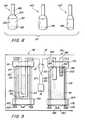
- FIG. 8is a side elevation view of a set of endermologie massage handpieces each offering a different size in order to permit control over the magnitude of suction and the area of application;
- FIG. 9is a front elevation view of a crystal supply station and crystal return station associated with the present invention.
- FIG. 1A preferred embodiment of the present invention is illustrated in FIG. 1 where a microdermabrasion and endermologie massage apparatus is designated by the reference numeral 10 .
- the apparatus 10includes a single housing 12 having a face plate 14 which is adapted for coupling through a flexible hose 15 to a microdermabrasion handpiece 16 and/or an endermologie handpiece 18 .
- a single source of vacuumsuch as a vacuum pump 21 .
- This pump 21is activated by a power switch 23 and coupled through a vacuum gauge 25 and bleed valve 27 to a 3-way mode switch 29 .
- the switch 29is in turn coupled to the microdermabrasion handpiece 16 and endermologie handpiece 18 .
- a crystal supply station 32 and crystal return station 34are disposed on the faceplate 14 of this embodiment.
- the vacuum pump 21is illustrated schematically in FIG. 2 and provides motive power for the apparatus 10 .
- the pump 21has an exhaust 36 and power sufficient to pull a stream of air 38 through a primary conduit 41 .
- the magnitude of air pressure within the conduit 41can be controlled by the bleed valve 27 which in the preferred embodiment is a needle valve.
- the primary conduit 41can be coupled to the 3-way valve or mode switch 29 .
- suctioncan be applied alternatively to an endermologie suction 43 or a microdermabrasion section 45 of the apparatus 10 .
- the switch 29can be used to divert the stream of air 38 alternatively to form a first air stream 49 in a secondary conduit 52 in the endermologie section 43 , or alternatively to form a first stream of air 47 in a secondary conduit 54 in the microdermabrasion section 45 , or alternatively a second stream of air 49 in a secondary conduit 52 in the endermologie section 43 .
- a second air stream 49 in a secondary conduit 52provides suction at the handpiece 18 .
- the first air stream 49then passes back through the flexible hose 17 and into the mode switch 29 where the stream of air 38 is drawn through the primary conduit 41 by the vacuum pump 21 .
- the mode switch 29can be set to draw the first air stream 47 through the conduit 54 in the microdermabrasion section 45 .
- the conduit 54is in turn coupled through HEPA filters 56 , the crystal return station 34 , the crystal supply station 32 and a second HEPA filter 58 .
- the filter 58in this case provides an air inlet 61 to the microdermabrasion section 45 .
- a supply of crystals 63is disposed at the crystal supply station 32 where the secondary conduit 54 is connected to a pick-up tube 64 in a canister 65 .
- the pick-up tube 64can be provided with a crystal pick-up 66 which extends into the crystals 63 within the canister 65 .
- a flow of the crystal 63can be provided in the first air stream 47 as it is introduced through a supply lumen 67 in the flexible hose 15 .
- the supply lumen 67in turn introduces the flow of crystals 63 to the microdermabrasion handpiece 16 which is adapted to be held by the surgeon or technician and applied to the skin of the patient.
- bypass valve 68which extends between the HEPA filter 58 and the supply lumen 67 of the handpiece 16 .
- the bypass valve 68effectively extends across the inlet and the outlet of the crystal supply station 32 .
- suctionis applied directly to the filter 58 and a portion of the air which would otherwise be input to the crystal supply station 32 is diverted to the output of the crystal supply station 32 .
- the flow of air in the pickup tube 64is decreased and the volume of crystals introduced into the crystal pickup 67 is commensurately reduced.
- the bypass airis recombined with the air in the pickup tube 64 so that the velocity of air introduced to the handpiece 16 is substantially constant. However, with a decrease in the volume of crystals introduced into the pickup tube 64 , the density of the crystals is reduced.
- the bypass valve 68provides a mechanism for varying the crystal density without significantly adjusting the crystal velocity.
- the used crystals 63can be removed from the handpiece 16 through a return lumen 69 in the flexible hose 15 . This flow of crystals 63 from the handpiece 16 is directed into the crystal return station 34 , which is discussed in greater detail below.
- the debris and used crystalsare removed from the first air stream 47 at the return station 34 , as the first air stream 47 is directed through the filters 56 and the conduit 54 to the 3-way valve or mode switch 29 . This completes the microdermabrasion section 45 of the embodiment.
- the microdermabrasion section 45would be activated through the 3-way mode selection switch 29 to facilitate skin abrasion by way of the handpiece 16 .
- the mode switch 29could be moved to its alternate position thereby activating the endermologie section 43 .
- FIG. 3is an exploded view showing a handle 72 having an axis 73 extending longitudinally between a proximal end 74 and a distal end 76 .
- An air stream control device 78is disposed at the distal end 76 of the handle 72 in fluid communication with the lumens 67 and 69 and the flexible hose 15 .
- the device 78can be provided with external threads 81 which register with internal threads 83 on a cap 85 .
- the cap 85can be friction fit onto the device 78 to facilitate a proper orientation of these two structures.
- the cap 85can be provided with a knurled circumference 87 and an end wall 89 which forms with the device 78 and abrasion chamber 92 .
- An abrasion window 94 in the end wall 89provides access to the abrasion chamber 92 .
- a preferred embodiment 86 of the air stream control device 78is illustrated in greater detail in the front elevation view of FIG. 4 and the cross-section view of FIG. 5 . From these views it can be seen that the device 78 can include a supply nozzle 101 which is disposed in fluid communication with the lumen 67 of the hose 15 . The nozzle 101 receives the flow of crystals 63 from the supply lumen 67 and introduces that flow into the abrasion chamber 92 . Importantly in this case, the nozzle 101 is positioned to direct the flow of crystals from the lumen 67 into the window 94 .
- the nozzle 101is disposed at an angle ⁇ relative to the axis 73 .
- the flow of crystals 63can be directed along a supply path 103 which has a distal component and an angle ⁇ relative to the axis 73 .
- the used crystalsare then drawn along a return path 105 to an orifice 107 in the device 78 .
- This orifice 107is in fluid communication with the return lumen 69 of the hose 15 which sucks the crystals 63 into the hose 15 and from the hose 15 into the return station 34 .
- the window 94has the configuration of a circle having its center disposed along the axis 73 .
- Other shapes for the window 94have been found particularly advantageous.
- the window 94has the configuration of a rectangle 109 having a long side 112 .
- This window 109is formed in an end wall 114 which has a generally planer configuration and is positioned at an angle to the axis 73 .
- the window 109is formed in the end wall 114 with its long side 112 disposed generally parallel to a plane 116 (FIG. 4) passing through the nozzle 101 and orifice 107 .
- a rectangular window 118 similar to the window 109 and having a long side 121is disposed in an end wall 123 .
- This end wall 123has a generally planer configuration and is disposed generally perpendicular to the axis 73 .
- Extending from the window 118are opposing sidewalls 127 and 129 which extend proximally outwardly from the associated long sides of the window 118 .
- the sidewall 127extends generally parallel to the long side 121 of the window 118 .
- Both of the side walls 127 and 129are disposed in respective planes 132 and 134 which are generally parallel to the long side 121 and have an angular relationship with the axis 73 .
- the planes 132 and 134 of the sidewalls 27 and 29are generally perpendicular to each other.
- FIG. 8illustrates a set 141 of three endermologie handpieces 143 , 145 and 147 .
- the handpiece 143includes a handle section 149 which typically has a cylindrical configuration and a diameter which is comfortable for the surgeon or technician to hold in his hand.
- An operative section 152is disposed distally of the handle section 149 and provided with a finger hole 153 .
- This operative section 152may also have a cylindrical configuration but will typically have a diameter greater than that of the handle section 149 .
- a conical transition section 154can be disposed between the handle section 149 and the operative section 152 .
- a suction window 156 at the distal end of the handpiece 143will typically have a diameter equivalent to that of the operative section 152 .
- the handpieces 145 and 147can be similar to the handpiece 143 in that they will typically. include a handle section, such as the section 149 , and an operative section, such as the section 152 .
- the diameter of the handle sectionsmay be equivalent to the diameter of the handle section 149 .
- the operative sections of the handpieces 145 and 147will typically have windows 146 and 148 , respectively, with diameters different than that of the window 156 in operative section 152 .
- the set 141will offer the surgeon or technician a choice of handpieces 143 , 145 and 147 each having a suction window, such as the window 156 , of different diameters. By selecting a particular one of the handpieces 143 - 147 , a different suction pressure and size of operative area can be chosen.
- these stations 32 and 34each include a bottom support 158 typically fixed to the face plate 14 , and a top support 161 which is attached to posts 163 that extend through holes in the bottom support 158 . Beneath the bottom support 158 , the posts 163 are threaded, passed through associated springs 165 , and terminated in associated nuts 167 . Since the top support 161 is typically not fixed to the faceplate 14 , it can be biased by the springs 165 from an extended relationship to a closely spaced relationship with the bottom support 158 .
- This structureenables the top support 161 to be moved upwardly to the extended relationship thereby permitting insertion of the canister 65 of crystals 63 .
- the top support 161can be released permitting the springs 165 to bias the top support 161 into the closely spaced relationship with the bottom support 158 , thereby capturing the canister 65 .
- the crystal return station 34can be similarly constructed with a bottom support 169 , top support 172 , post 174 , springs 176 and nuts 178 . Operation of this structure at the crystal return station 34 can similarly permit the removable installation of a disposable canister 181 .
- the first air streamcan be introduced through the pick-up tube 64 which extends into the crystals 63 within the canister 65 .
- This tube 64will typically have a U-shaped configuration thereby permitting accommodating both ends of the tubes 64 to extend through the top support 161 while allowing an intermediate section of the tube 64 to be deeply embedded the crystal 63 .
- the crystal pick-up 66is preferably disposed in this intermediate section 183 near the bottom of the canister 65 .
- the pick up 66is formed as a hole in the wall of the tube 64 thereby providing access for the crystals 63 into the first air stream 47 in the tube 64 .
- the hole 66can be carefully sized to control the amount of crystals introduced into the tube 64 per unit volume of the first air stream 47 .
- the larger the hole 66the greater the amount of crystal introduced into the stream and therefore the higher the crystal density within the first air stream.
- the crystal return station 34can be constructed in a manner similar to that of the crystal supply station 32 except that the input to the station 34 is provided by an inlet tube 184 in communication with the return lumen 69 from the tube 15 , and an exit tube 186 in communication with secondary conduit 54 the first air stream 47 . Otherwise, the bottom support 169 , top support 172 , post 174 , springs 176 and nuts 178 can function in the manner previously discussed to permit the removable insertion of the canister 181 .
- the canister 181can be provided with an O-ring 187 which defines an inlet hole 189 into the canister 181 .
- This O-ring 187forms a seal with the inlet tube 184 , which is in fluid communication with the return lumen 69 of the handpiece 16 .
- a downspout 192extends from the O-ring 187 into proximity with the opposite end of the canister 181 .
- the debris and used crystals 63exit the handpiece 16 , they travel along the return lumen 69 and the inlet tube 184 to the return station 32 , where they pass through the downspout 192 and are collected in the canister 181 .
- clean airis provided to the secondary conduit 54 which extends through a hole 196 defined by an O-ring 198 disposed in the top of the canister 181 .
- Attached to the O-ring 198is a filter 203 which is preferably pleated and may be formed of paper or fabric.
- the filter 203provides filtration of the air exiting the crystal return station 34 into the conduit 54 . Since this exit air forms the first air stream which in turn must pass through the 3-way mode selector valve 29 and the vacuum pump 21 , it is important that the crystals 63 , and any fragments thereof, be removed by this exit filter 203 .
- the canister 181When the canister 181 is full, it can be removed by elevating the top support 172 against the bias of the springs 176 and withdrawing the canister 181 and its O-rings 187 and 196 from the associated tubes 184 and 186 . The full canister 181 can then be discarded and replaced with an empty canister 181 .
- the canister 181can be made non-disposable and provided with a drain tube 188 and removable hemostat 190 . This configuration will enable the contents of the canister 181 to be removed through the drain 188 and collected in a biologically hazardous bag.
- a similar drain and hemostatcan be used with a non-disposable canister 65 in the crystal supply station 32 . This configuration will enable various grit sizes to be changed through the associated drain.
- Another feature of the present inventionaccommodates the need for back flushing all or various components of the system under certain circumstances. For example, if one of the crystals 63 becomes lodged in the hole 66 of the pickup tube 64 , it may be desirable to blow air in a reverse direction through the crystal supply station 32 . Realizing that the vacuum pump 21 will typically have an output of pressurized fluid, these and similar circumstances can be accommodated by connecting various components of the system to the output of the vacuum pump 21 . The pressurized air available at this location would then be introduced into the system in a reverse direction to back flush various components. In the example noted, the output of the crystal supply station 32 could be connected to the output of the vacuum pump 21 to back flush the hole 66 and dislodge any crystals. Other components of the system which might be connected to the output of the vacuum pump 21 might include for example the conduit 41 as well as the conduits 52 and 54 , the return lumen 69 of the handpiece 16 , or the exit tube 186 .
- microdermabrasion section 45 and endermologie section 43can be combined in a single unit and operated from a single vacuum source and mode selector switch. Only a single unit need be purchased by the surgeon or technician in order to perform both functions. This will be particularly appreciated in those procedures where the microdermabrasion process is facilitated by suction massage.
- Providing for pick up of the crystals 63 through the hole 66 directly into the tube 64is of particular advantage and permits control over the crystal density with an appropriate choice of diameter for the crystal pick-up hole 185 .
- the provision of separate valves 27 and 68 in the microdermabrasion section 45greatly increases the control over crystal density and velocity. Where the bleed valve 27 controls crystal velocity but not crystal density, the bypass valve 68 controls crystal density but not crystal velocity.
Landscapes
- Health & Medical Sciences (AREA)
- Life Sciences & Earth Sciences (AREA)
- Animal Behavior & Ethology (AREA)
- Veterinary Medicine (AREA)
- Surgery (AREA)
- Public Health (AREA)
- General Health & Medical Sciences (AREA)
- Engineering & Computer Science (AREA)
- Molecular Biology (AREA)
- Medical Informatics (AREA)
- Heart & Thoracic Surgery (AREA)
- Biomedical Technology (AREA)
- Nuclear Medicine, Radiotherapy & Molecular Imaging (AREA)
- Epidemiology (AREA)
- Pain & Pain Management (AREA)
- Physical Education & Sports Medicine (AREA)
- Rehabilitation Therapy (AREA)
- Surgical Instruments (AREA)
Abstract
Description
Claims (21)
Priority Applications (3)
| Application Number | Priority Date | Filing Date | Title |
|---|---|---|---|
| US09/540,945US6592595B1 (en) | 2000-03-31 | 2000-03-31 | Microdermabrasion and suction massage apparatus and method |
| US09/698,409US6527783B1 (en) | 2000-03-31 | 2000-10-27 | Microdermabrasion and suction massage apparatus and method |
| US10/177,173US6673082B2 (en) | 2000-03-31 | 2002-06-20 | Microdermabrasion handpiece with supply and return lumens |
Applications Claiming Priority (1)
| Application Number | Priority Date | Filing Date | Title |
|---|---|---|---|
| US09/540,945US6592595B1 (en) | 2000-03-31 | 2000-03-31 | Microdermabrasion and suction massage apparatus and method |
Related Child Applications (2)
| Application Number | Title | Priority Date | Filing Date |
|---|---|---|---|
| US09/698,409ContinuationUS6527783B1 (en) | 2000-03-31 | 2000-10-27 | Microdermabrasion and suction massage apparatus and method |
| US10/177,173DivisionUS6673082B2 (en) | 2000-03-31 | 2002-06-20 | Microdermabrasion handpiece with supply and return lumens |
Publications (1)
| Publication Number | Publication Date |
|---|---|
| US6592595B1true US6592595B1 (en) | 2003-07-15 |
Family
ID=24157548
Family Applications (3)
| Application Number | Title | Priority Date | Filing Date |
|---|---|---|---|
| US09/540,945Expired - LifetimeUS6592595B1 (en) | 2000-03-31 | 2000-03-31 | Microdermabrasion and suction massage apparatus and method |
| US09/698,409Expired - LifetimeUS6527783B1 (en) | 2000-03-31 | 2000-10-27 | Microdermabrasion and suction massage apparatus and method |
| US10/177,173Expired - LifetimeUS6673082B2 (en) | 2000-03-31 | 2002-06-20 | Microdermabrasion handpiece with supply and return lumens |
Family Applications After (2)
| Application Number | Title | Priority Date | Filing Date |
|---|---|---|---|
| US09/698,409Expired - LifetimeUS6527783B1 (en) | 2000-03-31 | 2000-10-27 | Microdermabrasion and suction massage apparatus and method |
| US10/177,173Expired - LifetimeUS6673082B2 (en) | 2000-03-31 | 2002-06-20 | Microdermabrasion handpiece with supply and return lumens |
Country Status (1)
| Country | Link |
|---|---|
| US (3) | US6592595B1 (en) |
Cited By (28)
| Publication number | Priority date | Publication date | Assignee | Title |
|---|---|---|---|---|
| US20030130628A1 (en)* | 2002-01-08 | 2003-07-10 | Duffy David M. | Method and apparatus for the treatment of scar tissue and wrinkles |
| US20040243031A1 (en)* | 2002-02-21 | 2004-12-02 | Calvert Jay Wynn | Massager and method of using same |
| US20050020966A1 (en)* | 2002-07-22 | 2005-01-27 | Holger Soring | Medical treatment apparatus |
| US20050096682A1 (en)* | 2003-11-05 | 2005-05-05 | Visibelle Derma Institute, Inc. | Vibratory blade device for body treatments |
| US20060047288A1 (en)* | 2004-08-31 | 2006-03-02 | Vierk Dan A | DiamAbrasion system |
| US20070156124A1 (en)* | 2005-12-30 | 2007-07-05 | Roger Ignon | Apparatus and methods for treating the skin |
| US20100137256A1 (en)* | 2008-11-28 | 2010-06-03 | Colette Haddad | Device and Method for Treating Human Body |
| US20110009882A1 (en)* | 2010-09-22 | 2011-01-13 | Irina Remsburg | Microdermabrasion hand piece providing automatic limitation of skin hyperextension |
| US8221437B2 (en) | 2009-11-25 | 2012-07-17 | Altair Instruments, Inc. | Device for applying liquid skincare products in combination with vacuum and abrasion |
| US8343116B2 (en) | 2008-01-04 | 2013-01-01 | Edge Systems Corporation | Apparatus and method for treating the skin |
| US8814836B2 (en) | 2008-01-29 | 2014-08-26 | Edge Systems Llc | Devices, systems and methods for treating the skin using time-release substances |
| USD716446S1 (en) | 2012-02-28 | 2014-10-28 | Riiviva, Inc. | Handheld microdermabrasion device |
| US9056193B2 (en) | 2008-01-29 | 2015-06-16 | Edge Systems Llc | Apparatus and method for treating the skin |
| USD741482S1 (en) | 2013-02-22 | 2015-10-20 | Riiviva, LLC | Collection canister for a microdermabrasion device |
| US9468464B2 (en) | 1999-08-26 | 2016-10-18 | Axia Medsciences, Llc | Methods for treating the skin using vacuum |
| US9498610B2 (en) | 2014-12-23 | 2016-11-22 | Edge Systems Llc | Devices and methods for treating the skin using a rollerball or a wicking member |
| US9566088B2 (en) | 2006-03-29 | 2017-02-14 | Edge Systems Llc | Devices, systems and methods for treating the skin |
| US10172644B2 (en) | 2006-03-29 | 2019-01-08 | Edge Systems Llc | Devices, systems and methods for treating the skin |
| US10179229B2 (en) | 2014-12-23 | 2019-01-15 | Edge Systems Llc | Devices and methods for treating the skin using a porous member |
| US10238812B2 (en) | 2013-03-15 | 2019-03-26 | Edge Systems Llc | Skin treatment systems and methods using needles |
| US10993743B2 (en) | 2013-03-15 | 2021-05-04 | Edge Systems Llc | Devices, systems and methods for treating the skin |
| US20210128416A1 (en)* | 2016-07-25 | 2021-05-06 | Allan Danto | Positive pressure flow skin abrasion system and method for dermal rejuvenation |
| US11241357B2 (en) | 2015-07-08 | 2022-02-08 | Edge Systems Llc | Devices, systems and methods for promoting hair growth |
| USD1016615S1 (en) | 2021-09-10 | 2024-03-05 | Hydrafacial Llc | Container for a skin treatment device |
| USD1042807S1 (en) | 2021-10-11 | 2024-09-17 | Hydrafacial Llc | Skin treatment tip |
| USD1065551S1 (en) | 2021-09-10 | 2025-03-04 | Hydrafacial Llc | Skin treatment device |
| US12295618B2 (en) | 2020-01-06 | 2025-05-13 | Hydrafacial Llc | Skin treatment tool applicator tip |
| USD1084369S1 (en) | 2023-02-10 | 2025-07-15 | Hydrafacial Llc | Skin treatment tip |
Families Citing this family (29)
| Publication number | Priority date | Publication date | Assignee | Title |
|---|---|---|---|---|
| US7267675B2 (en)* | 1996-01-05 | 2007-09-11 | Thermage, Inc. | RF device with thermo-electric cooler |
| US7473251B2 (en)* | 1996-01-05 | 2009-01-06 | Thermage, Inc. | Methods for creating tissue effect utilizing electromagnetic energy and a reverse thermal gradient |
| US7229436B2 (en) | 1996-01-05 | 2007-06-12 | Thermage, Inc. | Method and kit for treatment of tissue |
| US20030093089A1 (en)* | 1999-10-20 | 2003-05-15 | Greenberg Ronald Allan | Apparatus for variable micro abrasion of human tissue and/or hides using different size and types of abrasive particles |
| US6980854B2 (en)* | 2001-04-06 | 2005-12-27 | Mattioli Engineering Ltd. | Method and apparatus for skin absorption enhancement and transdermal drug delivery of lidocaine and/or other drugs |
| US6743215B2 (en)* | 2001-04-06 | 2004-06-01 | Mattioli Engineering Ltd. | Method and apparatus for skin absorption enhancement and cellulite reduction |
| US7520875B2 (en)* | 2001-04-06 | 2009-04-21 | Mattioli Engineering Ltd. | Method and apparatus for skin absorption enhancement and transdermal drug delivery |
| US7496401B2 (en)* | 2001-04-06 | 2009-02-24 | Mattioli Engineering Ltd | Method and apparatus for skin absorption enhancement and transdermal drug delivery |
| US7010343B2 (en) | 2001-04-06 | 2006-03-07 | Mattioli Engineering Ltd. | Method and apparatus for skin absorption enhancement and transdermal drug delivery |
| US7083580B2 (en)* | 2001-04-06 | 2006-08-01 | Mattioli Engineering Ltd. | Method and apparatus for skin absorption enhancement and transdermal drug delivery |
| US6687537B2 (en)* | 2001-04-06 | 2004-02-03 | Mattioli Engineering Ltd. | Method and apparatus for skin absorption enhancement and cellulite reduction |
| JP2006503627A (en) | 2002-10-21 | 2006-02-02 | ビオノファス | Micro peeling device |
| USD544955S1 (en)* | 2003-02-05 | 2007-06-19 | Thermage, Inc. | Medical device tip |
| US7044955B2 (en)* | 2003-05-27 | 2006-05-16 | Focus Medical, Llc | Removable cartridge for a microdermabrasion unit |
| USD506550S1 (en)* | 2003-06-26 | 2005-06-21 | Ronald Allan Greenberg | Microdermabrasion hand tool tip |
| GB2437212B (en)* | 2004-01-21 | 2008-06-11 | Crystal Clear Internat Ltd | Microdermabrasion device |
| GB0401550D0 (en)* | 2004-01-21 | 2004-02-25 | Ball Philip | A handheld apparatus for use in micro-dermabrasion |
| US20050283176A1 (en)* | 2004-06-22 | 2005-12-22 | Wahson Law | Advanced disposable microdermabrasion system/method of treating the skin surface |
| US7318828B1 (en)* | 2004-09-20 | 2008-01-15 | Jacob Revivo | Microdermabrasion machine |
| US20090299266A1 (en)* | 2008-06-02 | 2009-12-03 | Mattioli Engineering Ltd. | Method and apparatus for skin absorption enhancement and transdermal drug delivery |
| PT2361598T (en) | 2010-02-22 | 2017-03-17 | Mc Health Tech S L | Support device for a skin treatment assembly |
| US9052047B2 (en)* | 2010-06-03 | 2015-06-09 | Keith Covert | Quick connect coupler for glass container molding machine |
| US9775645B2 (en) | 2013-03-01 | 2017-10-03 | Envy Medical, Inc. | Microdermabrasion system with ergonomic handle |
| USD862721S1 (en) | 2018-07-12 | 2019-10-08 | Michael Todd Beauty Lp | Personal care appliance |
| US11504148B2 (en) | 2018-07-12 | 2022-11-22 | Michael Todd Beauty Lp | Personal care appliance |
| USD1039711S1 (en) | 2023-02-28 | 2024-08-20 | Access Business Group International Llc | Skin treatment device |
| USD1051832S1 (en) | 2023-02-28 | 2024-11-19 | Access Business Group International Llc | Cradle for skin treatment system |
| USD1049405S1 (en) | 2023-02-28 | 2024-10-29 | Access Business Group International Llc | Skin treatment system |
| USD1047180S1 (en) | 2023-02-28 | 2024-10-15 | Access Business Group International Llc | Skin treatment device |
Citations (28)
| Publication number | Priority date | Publication date | Assignee | Title |
|---|---|---|---|---|
| US2701559A (en) | 1951-08-02 | 1955-02-08 | William A Cooper | Apparatus for exfoliating and collecting diagnostic material from inner walls of hollow viscera |
| US2712823A (en) | 1954-02-24 | 1955-07-12 | Kurtin Abuer | Brush for removing skin blemishes |
| US2867214A (en) | 1956-02-14 | 1959-01-06 | Ralph Luikart Ii | Skin treating apparatus |
| US2881763A (en) | 1956-08-30 | 1959-04-14 | Robbins Noel | Surgical handpiece |
| US2921585A (en) | 1955-07-01 | 1960-01-19 | Reinhold S Schumann | Device for the treatment of skin diseases such as skin overgrowths, eruptions and the like or other skin disfigurements |
| US3964212A (en) | 1974-03-22 | 1976-06-22 | Atlas Copco Aktiebolag | Pneumatic grinding machine provided with dust removing means |
| US4378804A (en) | 1981-06-17 | 1983-04-05 | Cortese Jr Thomas A | Facial treatment device |
| US4957747A (en) | 1989-05-15 | 1990-09-18 | Stiefel Laboratories, Inc. | Method of treating aged skin |
| US5012797A (en) | 1990-01-08 | 1991-05-07 | Montefiore Hospital Association Of Western Pennsylvania | Method for removing skin wrinkles |
| US5037432A (en) | 1987-11-27 | 1991-08-06 | Lorenzo Molinari | Adjustable apparatus for removing surface portions of human tissue |
| US5037431A (en) | 1989-11-03 | 1991-08-06 | The Curators Of The University Of Missouri | Surgical liquid lance apparatus |
| US5100412A (en) | 1988-01-11 | 1992-03-31 | L.I.C.A. Di Rosso & C. S.N.C. | Apparatus for making micro-abrasions, particularly on human tissue or on hides |
| US5154696A (en)* | 1991-04-08 | 1992-10-13 | Shearing Steven P | Phacoemulsification, irrigation and aspiration method and apparatus |
| US5207234A (en) | 1988-01-11 | 1993-05-04 | L.I.C.A. Di Rosso & C.S. N.C. | Method for making micro-abrasions on human tissue |
| US5800446A (en) | 1997-02-27 | 1998-09-01 | Banuchi; Isabel M. | Article and method for dermabrading |
| US5810842A (en)* | 1994-06-29 | 1998-09-22 | Mattioli Engineering S.R.L. | Equipment for microdermoabrasion through a flow of an air/reducing substances mix |
| US5954730A (en)* | 1996-05-10 | 1999-09-21 | Mattioli Engineering Ltd. | Mixing bottle for dermabrasion treatment and method of using the same |
| US5971999A (en)* | 1995-06-16 | 1999-10-26 | Naldoni; Moreno | Apparatus for microdermabrasion by means of a jet of mixture of air/reducing substances and relating handle |
| US6019749A (en) | 1998-04-01 | 2000-02-01 | Squeezease, Llc | Apparatus and method for removing material from skin pores |
| US6039745A (en) | 1995-06-29 | 2000-03-21 | Mattioli Engineering Ltd. | Equipment for microdermoabrasion through a flow of air/reducing substances mix and relative handpiece |
| US6042552A (en) | 1995-11-27 | 2000-03-28 | Laboratoire C.C.D. | Device for collecting endometrial fragments |
| US6080165A (en) | 1999-03-15 | 2000-06-27 | Dejacma; Frederick W. | Self-contained disposable handpiece for a skin tissue removing apparatus |
| US6196982B1 (en)* | 1995-10-30 | 2001-03-06 | Terry A. Ball | Vacuum massager |
| US6235039B1 (en)* | 1999-02-23 | 2001-05-22 | Roger C. Parkin | Skin abrasion device |
| US6241739B1 (en)* | 1999-11-12 | 2001-06-05 | Altair Instruments, Inc. | Microdermabrasion device and method of treating the skin surface |
| US6250996B1 (en)* | 1998-08-19 | 2001-06-26 | Alva Wesley Metcalf | Contained direct particle beam flow abrasion system |
| US20010023351A1 (en)* | 1999-12-01 | 2001-09-20 | Eilers George J. | Skin abrasion system and method |
| US6319211B1 (en)* | 1998-10-26 | 2001-11-20 | Matsushita Electric Works, Ltd. | Facial aesthetic treatment apparatus |
Family Cites Families (7)
| Publication number | Priority date | Publication date | Assignee | Title |
|---|---|---|---|---|
| US5207034A (en)* | 1990-06-25 | 1993-05-04 | Lynn William R | Pliant media blasting device |
| US5620414A (en)* | 1992-06-30 | 1997-04-15 | Campbell, Jr.; Robert M. | Apparatus and method for effecting surgical incision through use of a fluid jet |
| US6277003B1 (en)* | 1998-05-28 | 2001-08-21 | Danville Engineering | Gas abrasive particle apparatus and valving therefor |
| FR2783735B1 (en)* | 1998-09-29 | 2000-12-15 | Patrick Loubeyre | DEVICE FOR THE DECONTAMINATION OF SURFACES BY MEANS OF A JET COMPOSED OF AIR, A FINE-GRAINED SPRAYING MATERIAL AND A LIQUID |
| US6306119B1 (en) | 1999-01-20 | 2001-10-23 | Pearl Technology Holdings, Llc | Skin resurfacing and treatment using biocompatible materials |
| US6139554A (en)* | 1999-06-10 | 2000-10-31 | Karkar; Maurice N. | Multipurpose tissue resurfacing handpiece |
| US6303119B1 (en)* | 1999-09-22 | 2001-10-16 | The Procter & Gamble Company | Personal care compositions containing subtilisin enzymes bound to water insoluble substrates |
- 2000
- 2000-03-31USUS09/540,945patent/US6592595B1/ennot_activeExpired - Lifetime
- 2000-10-27USUS09/698,409patent/US6527783B1/ennot_activeExpired - Lifetime
- 2002
- 2002-06-20USUS10/177,173patent/US6673082B2/ennot_activeExpired - Lifetime
Patent Citations (28)
| Publication number | Priority date | Publication date | Assignee | Title |
|---|---|---|---|---|
| US2701559A (en) | 1951-08-02 | 1955-02-08 | William A Cooper | Apparatus for exfoliating and collecting diagnostic material from inner walls of hollow viscera |
| US2712823A (en) | 1954-02-24 | 1955-07-12 | Kurtin Abuer | Brush for removing skin blemishes |
| US2921585A (en) | 1955-07-01 | 1960-01-19 | Reinhold S Schumann | Device for the treatment of skin diseases such as skin overgrowths, eruptions and the like or other skin disfigurements |
| US2867214A (en) | 1956-02-14 | 1959-01-06 | Ralph Luikart Ii | Skin treating apparatus |
| US2881763A (en) | 1956-08-30 | 1959-04-14 | Robbins Noel | Surgical handpiece |
| US3964212A (en) | 1974-03-22 | 1976-06-22 | Atlas Copco Aktiebolag | Pneumatic grinding machine provided with dust removing means |
| US4378804A (en) | 1981-06-17 | 1983-04-05 | Cortese Jr Thomas A | Facial treatment device |
| US5037432A (en) | 1987-11-27 | 1991-08-06 | Lorenzo Molinari | Adjustable apparatus for removing surface portions of human tissue |
| US5100412A (en) | 1988-01-11 | 1992-03-31 | L.I.C.A. Di Rosso & C. S.N.C. | Apparatus for making micro-abrasions, particularly on human tissue or on hides |
| US5207234A (en) | 1988-01-11 | 1993-05-04 | L.I.C.A. Di Rosso & C.S. N.C. | Method for making micro-abrasions on human tissue |
| US4957747A (en) | 1989-05-15 | 1990-09-18 | Stiefel Laboratories, Inc. | Method of treating aged skin |
| US5037431A (en) | 1989-11-03 | 1991-08-06 | The Curators Of The University Of Missouri | Surgical liquid lance apparatus |
| US5012797A (en) | 1990-01-08 | 1991-05-07 | Montefiore Hospital Association Of Western Pennsylvania | Method for removing skin wrinkles |
| US5154696A (en)* | 1991-04-08 | 1992-10-13 | Shearing Steven P | Phacoemulsification, irrigation and aspiration method and apparatus |
| US5810842A (en)* | 1994-06-29 | 1998-09-22 | Mattioli Engineering S.R.L. | Equipment for microdermoabrasion through a flow of an air/reducing substances mix |
| US5971999A (en)* | 1995-06-16 | 1999-10-26 | Naldoni; Moreno | Apparatus for microdermabrasion by means of a jet of mixture of air/reducing substances and relating handle |
| US6039745A (en) | 1995-06-29 | 2000-03-21 | Mattioli Engineering Ltd. | Equipment for microdermoabrasion through a flow of air/reducing substances mix and relative handpiece |
| US6196982B1 (en)* | 1995-10-30 | 2001-03-06 | Terry A. Ball | Vacuum massager |
| US6042552A (en) | 1995-11-27 | 2000-03-28 | Laboratoire C.C.D. | Device for collecting endometrial fragments |
| US5954730A (en)* | 1996-05-10 | 1999-09-21 | Mattioli Engineering Ltd. | Mixing bottle for dermabrasion treatment and method of using the same |
| US5800446A (en) | 1997-02-27 | 1998-09-01 | Banuchi; Isabel M. | Article and method for dermabrading |
| US6019749A (en) | 1998-04-01 | 2000-02-01 | Squeezease, Llc | Apparatus and method for removing material from skin pores |
| US6250996B1 (en)* | 1998-08-19 | 2001-06-26 | Alva Wesley Metcalf | Contained direct particle beam flow abrasion system |
| US6319211B1 (en)* | 1998-10-26 | 2001-11-20 | Matsushita Electric Works, Ltd. | Facial aesthetic treatment apparatus |
| US6235039B1 (en)* | 1999-02-23 | 2001-05-22 | Roger C. Parkin | Skin abrasion device |
| US6080165A (en) | 1999-03-15 | 2000-06-27 | Dejacma; Frederick W. | Self-contained disposable handpiece for a skin tissue removing apparatus |
| US6241739B1 (en)* | 1999-11-12 | 2001-06-05 | Altair Instruments, Inc. | Microdermabrasion device and method of treating the skin surface |
| US20010023351A1 (en)* | 1999-12-01 | 2001-09-20 | Eilers George J. | Skin abrasion system and method |
Cited By (68)
| Publication number | Priority date | Publication date | Assignee | Title |
|---|---|---|---|---|
| US9775646B2 (en) | 1999-08-26 | 2017-10-03 | Axia Medsciences, Llc | Devices and systems for treating the skin using vacuum |
| US9468464B2 (en) | 1999-08-26 | 2016-10-18 | Axia Medsciences, Llc | Methods for treating the skin using vacuum |
| US20030130628A1 (en)* | 2002-01-08 | 2003-07-10 | Duffy David M. | Method and apparatus for the treatment of scar tissue and wrinkles |
| US20040243031A1 (en)* | 2002-02-21 | 2004-12-02 | Calvert Jay Wynn | Massager and method of using same |
| US7041072B2 (en)* | 2002-02-21 | 2006-05-09 | Matrix Surgical Consulting Corporation | Massager and method of using same |
| US20060155224A1 (en)* | 2002-02-21 | 2006-07-13 | Matrix Surgical Consulting Corporation | Massager and method of using same |
| US20050020966A1 (en)* | 2002-07-22 | 2005-01-27 | Holger Soring | Medical treatment apparatus |
| US7608054B2 (en)* | 2002-07-22 | 2009-10-27 | Soering Gmbh | Medical treatment apparatus |
| US20050096682A1 (en)* | 2003-11-05 | 2005-05-05 | Visibelle Derma Institute, Inc. | Vibratory blade device for body treatments |
| US20060047288A1 (en)* | 2004-08-31 | 2006-03-02 | Vierk Dan A | DiamAbrasion system |
| US7651508B2 (en) | 2004-08-31 | 2010-01-26 | Vierk Dan A | DiamAbrasion system |
| US11612726B2 (en) | 2005-12-30 | 2023-03-28 | Hydrafacial Llc | Devices and methods for treating skin |
| US9662482B2 (en) | 2005-12-30 | 2017-05-30 | Edge Systems Llc | Methods and systems for extraction of materials from skin |
| US11865287B2 (en) | 2005-12-30 | 2024-01-09 | Hydrafacial Llc | Devices and methods for treating skin |
| US10357641B2 (en) | 2005-12-30 | 2019-07-23 | Edge Systems Llc | Tips for skin treatment device |
| US9814868B2 (en) | 2005-12-30 | 2017-11-14 | Edge Systems Llc | Tip with embedded materials for skin treatment |
| US20070156124A1 (en)* | 2005-12-30 | 2007-07-05 | Roger Ignon | Apparatus and methods for treating the skin |
| US11547840B2 (en) | 2005-12-30 | 2023-01-10 | Hydrafacial Llc | Devices and methods for treating skin |
| US8048089B2 (en) | 2005-12-30 | 2011-11-01 | Edge Systems Corporation | Apparatus and methods for treating the skin |
| US11446477B2 (en) | 2005-12-30 | 2022-09-20 | Hydrafacial Llc | Devices and methods for treating skin |
| US12053607B2 (en) | 2005-12-30 | 2024-08-06 | Hydrafacial Llc | Devices and methods for treating skin |
| US9474886B2 (en) | 2005-12-30 | 2016-10-25 | Edge Systems Llc | Removable tips for skin treatment systems |
| US10357642B2 (en) | 2005-12-30 | 2019-07-23 | Edge Systems Llc | Removable tips for use with skin treatment systems |
| US9550052B2 (en) | 2005-12-30 | 2017-01-24 | Edge Systems Llc | Console system for the treatment of skin |
| US9566088B2 (en) | 2006-03-29 | 2017-02-14 | Edge Systems Llc | Devices, systems and methods for treating the skin |
| US10251675B2 (en) | 2006-03-29 | 2019-04-09 | Edge Systems Llc | Devices, systems and methods for treating the skin |
| US11717326B2 (en) | 2006-03-29 | 2023-08-08 | Hydrafacial Llc | Devices, systems and methods for treating the skin |
| US10172644B2 (en) | 2006-03-29 | 2019-01-08 | Edge Systems Llc | Devices, systems and methods for treating the skin |
| US10556096B2 (en) | 2008-01-04 | 2020-02-11 | Edge Systems Llc | Devices and methods for skin treatment |
| US9486615B2 (en) | 2008-01-04 | 2016-11-08 | Edge Systems Llc | Microdermabrasion apparatus and method |
| US11883621B2 (en) | 2008-01-04 | 2024-01-30 | Hydrafacial Llc | Devices and methods for skin treatment |
| US8343116B2 (en) | 2008-01-04 | 2013-01-01 | Edge Systems Corporation | Apparatus and method for treating the skin |
| US9056193B2 (en) | 2008-01-29 | 2015-06-16 | Edge Systems Llc | Apparatus and method for treating the skin |
| US8814836B2 (en) | 2008-01-29 | 2014-08-26 | Edge Systems Llc | Devices, systems and methods for treating the skin using time-release substances |
| US12186513B2 (en) | 2008-01-29 | 2025-01-07 | Hydrafacial Llc | Devices, systems and methods for skin treatment |
| US12161830B2 (en) | 2008-01-29 | 2024-12-10 | Hydrafacial Llc | Devices, systems, and methods for treating the skin |
| US9642997B2 (en) | 2008-01-29 | 2017-05-09 | Edge Systems Llc | Devices for treating skin using treatment materials located along a tip |
| US12005217B2 (en) | 2008-01-29 | 2024-06-11 | Hydrafacial Llc | Devices, systems and methods for skin treatment |
| US10556097B2 (en) | 2008-01-29 | 2020-02-11 | Edge Systems Llc | Devices for treating skin using treatment materials located along a tip |
| US11020577B2 (en) | 2008-01-29 | 2021-06-01 | Edge Systems Llc | Devices and systems for treating skin surfaces |
| US20100137256A1 (en)* | 2008-11-28 | 2010-06-03 | Colette Haddad | Device and Method for Treating Human Body |
| US8221437B2 (en) | 2009-11-25 | 2012-07-17 | Altair Instruments, Inc. | Device for applying liquid skincare products in combination with vacuum and abrasion |
| US20110009882A1 (en)* | 2010-09-22 | 2011-01-13 | Irina Remsburg | Microdermabrasion hand piece providing automatic limitation of skin hyperextension |
| US8226663B2 (en) | 2010-09-22 | 2012-07-24 | Irina Remsburg | Microdermabrasion hand piece providing automatic limitation of skin hyperextension |
| USD716446S1 (en) | 2012-02-28 | 2014-10-28 | Riiviva, Inc. | Handheld microdermabrasion device |
| USD741482S1 (en) | 2013-02-22 | 2015-10-20 | Riiviva, LLC | Collection canister for a microdermabrasion device |
| US11517350B2 (en) | 2013-03-15 | 2022-12-06 | Hydrafacial Llc | Devices, systems and methods for treating the skin |
| US11213321B2 (en) | 2013-03-15 | 2022-01-04 | Edge Systems Llc | Devices, systems and methods for treating the skin |
| US10993743B2 (en) | 2013-03-15 | 2021-05-04 | Edge Systems Llc | Devices, systems and methods for treating the skin |
| US10238812B2 (en) | 2013-03-15 | 2019-03-26 | Edge Systems Llc | Skin treatment systems and methods using needles |
| US11903615B2 (en) | 2013-03-15 | 2024-02-20 | Hydrafacial Llc | Devices, systems and methods for treating the skin |
| US11202657B2 (en) | 2013-03-15 | 2021-12-21 | Edge Systems Llc | Devices, systems and methods for treating the skin |
| US11925780B2 (en) | 2014-12-23 | 2024-03-12 | Hydrafacial Llc | Devices and methods for treating the skin |
| US10035007B2 (en) | 2014-12-23 | 2018-07-31 | Edge Systems Llc | Devices and methods for treating the skin |
| US11744999B2 (en) | 2014-12-23 | 2023-09-05 | Hydra Facial LLC | Devices and methods for treating the skin |
| US11224728B2 (en) | 2014-12-23 | 2022-01-18 | Edge Systems Llc | Devices and methods for treating the skin using a porous member |
| US10179229B2 (en) | 2014-12-23 | 2019-01-15 | Edge Systems Llc | Devices and methods for treating the skin using a porous member |
| US11806495B2 (en) | 2014-12-23 | 2023-11-07 | Hydrafacial Llc | Devices and methods for treating the skin |
| US9498610B2 (en) | 2014-12-23 | 2016-11-22 | Edge Systems Llc | Devices and methods for treating the skin using a rollerball or a wicking member |
| US11241357B2 (en) | 2015-07-08 | 2022-02-08 | Edge Systems Llc | Devices, systems and methods for promoting hair growth |
| US11980676B2 (en)* | 2016-07-25 | 2024-05-14 | Allan Danto | Dermal rejuvenation system |
| US20210128416A1 (en)* | 2016-07-25 | 2021-05-06 | Allan Danto | Positive pressure flow skin abrasion system and method for dermal rejuvenation |
| US12201706B2 (en)* | 2016-07-25 | 2025-01-21 | Allan Danto | Dermal rejuvenation system |
| US12295618B2 (en) | 2020-01-06 | 2025-05-13 | Hydrafacial Llc | Skin treatment tool applicator tip |
| USD1016615S1 (en) | 2021-09-10 | 2024-03-05 | Hydrafacial Llc | Container for a skin treatment device |
| USD1065551S1 (en) | 2021-09-10 | 2025-03-04 | Hydrafacial Llc | Skin treatment device |
| USD1042807S1 (en) | 2021-10-11 | 2024-09-17 | Hydrafacial Llc | Skin treatment tip |
| USD1084369S1 (en) | 2023-02-10 | 2025-07-15 | Hydrafacial Llc | Skin treatment tip |
Also Published As
| Publication number | Publication date |
|---|---|
| US20020151908A1 (en) | 2002-10-17 |
| US6527783B1 (en) | 2003-03-04 |
| US6673082B2 (en) | 2004-01-06 |
Similar Documents
| Publication | Publication Date | Title |
|---|---|---|
| US6592595B1 (en) | Microdermabrasion and suction massage apparatus and method | |
| US20060253125A1 (en) | Microdermabrasion method and apparatus | |
| US11839390B2 (en) | Method for reducing biofilm formation | |
| US6039745A (en) | Equipment for microdermoabrasion through a flow of air/reducing substances mix and relative handpiece | |
| US5947990A (en) | Endoscopic surgical instrument | |
| EP0831748B1 (en) | Apparatus for microdermabrasion by means of a jet of a mixture of air/reducing substances and relating handle | |
| JP7159184B2 (en) | Methods of reducing or removing biological membranes | |
| US8337513B2 (en) | Instruments and techniques for controlled removal of epidermal layers | |
| US6129701A (en) | Vented aspirator and method | |
| US5520667A (en) | Methods for bone and other tissue preparation | |
| US4536180A (en) | Surgical instrument for suction lipolysis | |
| US6162232A (en) | Instruments and techniques for high-velocity fluid abrasion of epidermal layers with skin cooling | |
| WO2004002334A1 (en) | Surgical instrument | |
| JP2004523253A (en) | Inhalation and irrigation instruments for surgical endoscopes | |
| WO1997011650A1 (en) | Apparatus and method for microdermoabrasion | |
| US20010049511A1 (en) | Water jet for dermatological treatment | |
| US12329396B2 (en) | Kidney stone treatment system | |
| WO2024104040A1 (en) | Bent combined ureteroscope, ureteroscope, and ureteroscope main body | |
| WO2006093900A2 (en) | Multi-functional medical instrument and methods of use | |
| CN114468969A (en) | Endoscope with renal pelvis stone removing function, system and application method | |
| KR102566128B1 (en) | Medical one-touch 3-way stopcock | |
| JP2576296Y2 (en) | Circulating bladder aspirator | |
| CN109745100A (en) | A soft tissue debridement knife based on endoscopic technology | |
| CN117017423A (en) | Bladder lithotripter convenient to adjust | |
| HK40017235B (en) | Method for reducing or removing biofilm |
Legal Events
| Date | Code | Title | Description |
|---|---|---|---|
| AS | Assignment | Owner name:EDGE SYSTEMS CORPORATION, CALIFORNIA Free format text:ASSIGNMENT OF ASSIGNORS INTEREST;ASSIGNORS:MALLETT, SCOTT R.;COHEN, WILLIAM;IGNON, ROGER G.;REEL/FRAME:013505/0146;SIGNING DATES FROM 20020906 TO 20020909 | |
| STCF | Information on status: patent grant | Free format text:PATENTED CASE | |
| FPAY | Fee payment | Year of fee payment:4 | |
| FEPP | Fee payment procedure | Free format text:PAYER NUMBER DE-ASSIGNED (ORIGINAL EVENT CODE: RMPN); ENTITY STATUS OF PATENT OWNER: SMALL ENTITY Free format text:PAYOR NUMBER ASSIGNED (ORIGINAL EVENT CODE: ASPN); ENTITY STATUS OF PATENT OWNER: SMALL ENTITY | |
| FPAY | Fee payment | Year of fee payment:8 | |
| AS | Assignment | Owner name:COMERICA BANK, A TEXAS BANKING ASSOCIATION, MICHIG Free format text:SECURITY AGREEMENT;ASSIGNORS:EDGE SYSTEMS INTERMEDIATE CORPORATION;EDGE SYSTEMS LLC;REEL/FRAME:029549/0027 Effective date:20121218 | |
| FPAY | Fee payment | Year of fee payment:12 | |
| AS | Assignment | Owner name:EDGE SYSTEMS INTERMEDIATE CORPORATION, CALIFORNIA Free format text:RELEASE OF SECURITY INTEREST RECORDED AT REEL/FRAME 029549/0027;ASSIGNOR:COMERICA BANK;REEL/FRAME:040806/0018 Effective date:20161129 Owner name:EDGE SYSTEMS LLC, CALIFORNIA Free format text:RELEASE OF SECURITY INTEREST RECORDED AT REEL/FRAME 029549/0027;ASSIGNOR:COMERICA BANK;REEL/FRAME:040806/0018 Effective date:20161129 | |
| AS | Assignment | Owner name:SILVER POINT FINANCE, LLC, CONNECTICUT Free format text:SECURITY INTEREST;ASSIGNORS:EDGE SYSTEMS INTERMEDIATE CORPORATION;EDGE SYSTEMS LLC;REEL/FRAME:040538/0026 Effective date:20161201 | |
| AS | Assignment | Owner name:EDGE SYSTEMS LLC, CALIFORNIA Free format text:CONVERSION;ASSIGNOR:EDGE SYSTEMS CORPORATION;REEL/FRAME:051724/0655 Effective date:20121203 | |
| AS | Assignment | Owner name:EDGE SYSTEMS INTERMEDIATE, LLC, NEW YORK Free format text:RELEASE BY SECURED PARTY;ASSIGNOR:SILVER POINT FINANCE, LLC;REEL/FRAME:056675/0606 Effective date:20210505 Owner name:EDGE SYSTEMS LLC, NEW YORK Free format text:RELEASE BY SECURED PARTY;ASSIGNOR:SILVER POINT FINANCE, LLC;REEL/FRAME:056675/0606 Effective date:20210505 | |
| AS | Assignment | Owner name:JPMORGAN CHASE BANK, N.A., AS ADMINISTRATIVE AGENT, ILLINOIS Free format text:SECURITY INTEREST;ASSIGNOR:EDGE SYSTEMS LLC;REEL/FRAME:058526/0897 Effective date:20211230 | |
| AS | Assignment | Owner name:HYDRAFACIAL LLC (FORMERLY KNOWN AS EDGE SYSTEMS LLC), CALIFORNIA Free format text:RELEASE OF SECURITY INTEREST IN PATENTS AT REEL/FRAME NO. 58526/0897;ASSIGNOR:JPMORGAN CHASE BANK, N.A., AS ADMINISTRATIVE AGENT;REEL/FRAME:068378/0060 Effective date:20240806 |