US6592582B2 - Vessel harvesting retractor with electrosurgical plunger - Google Patents
Vessel harvesting retractor with electrosurgical plungerDownload PDFInfo
- Publication number
- US6592582B2 US6592582B2US09/966,858US96685801AUS6592582B2US 6592582 B2US6592582 B2US 6592582B2US 96685801 AUS96685801 AUS 96685801AUS 6592582 B2US6592582 B2US 6592582B2
- Authority
- US
- United States
- Prior art keywords
- vessel
- plunger
- headpiece
- side branch
- harvesting device
- Prior art date
- Legal status (The legal status is an assumption and is not a legal conclusion. Google has not performed a legal analysis and makes no representation as to the accuracy of the status listed.)
- Expired - Fee Related, expires
Links
Images


Classifications
- A—HUMAN NECESSITIES
- A61—MEDICAL OR VETERINARY SCIENCE; HYGIENE
- A61B—DIAGNOSIS; SURGERY; IDENTIFICATION
- A61B17/00—Surgical instruments, devices or methods
- A61B17/00008—Vein tendon strippers
- A—HUMAN NECESSITIES
- A61—MEDICAL OR VETERINARY SCIENCE; HYGIENE
- A61B—DIAGNOSIS; SURGERY; IDENTIFICATION
- A61B18/00—Surgical instruments, devices or methods for transferring non-mechanical forms of energy to or from the body
- A61B18/04—Surgical instruments, devices or methods for transferring non-mechanical forms of energy to or from the body by heating
- A61B18/12—Surgical instruments, devices or methods for transferring non-mechanical forms of energy to or from the body by heating by passing a current through the tissue to be heated, e.g. high-frequency current
- A61B18/14—Probes or electrodes therefor
- A61B18/1482—Probes or electrodes therefor having a long rigid shaft for accessing the inner body transcutaneously in minimal invasive surgery, e.g. laparoscopy
- A—HUMAN NECESSITIES
- A61—MEDICAL OR VETERINARY SCIENCE; HYGIENE
- A61B—DIAGNOSIS; SURGERY; IDENTIFICATION
- A61B18/00—Surgical instruments, devices or methods for transferring non-mechanical forms of energy to or from the body
- A61B2018/00315—Surgical instruments, devices or methods for transferring non-mechanical forms of energy to or from the body for treatment of particular body parts
- A61B2018/00345—Vascular system
- A61B2018/00404—Blood vessels other than those in or around the heart
- A—HUMAN NECESSITIES
- A61—MEDICAL OR VETERINARY SCIENCE; HYGIENE
- A61B—DIAGNOSIS; SURGERY; IDENTIFICATION
- A61B18/00—Surgical instruments, devices or methods for transferring non-mechanical forms of energy to or from the body
- A61B2018/00571—Surgical instruments, devices or methods for transferring non-mechanical forms of energy to or from the body for achieving a particular surgical effect
- A61B2018/00595—Cauterization
- A—HUMAN NECESSITIES
- A61—MEDICAL OR VETERINARY SCIENCE; HYGIENE
- A61B—DIAGNOSIS; SURGERY; IDENTIFICATION
- A61B18/00—Surgical instruments, devices or methods for transferring non-mechanical forms of energy to or from the body
- A61B2018/00571—Surgical instruments, devices or methods for transferring non-mechanical forms of energy to or from the body for achieving a particular surgical effect
- A61B2018/00601—Cutting
- A—HUMAN NECESSITIES
- A61—MEDICAL OR VETERINARY SCIENCE; HYGIENE
- A61B—DIAGNOSIS; SURGERY; IDENTIFICATION
- A61B18/00—Surgical instruments, devices or methods for transferring non-mechanical forms of energy to or from the body
- A61B18/04—Surgical instruments, devices or methods for transferring non-mechanical forms of energy to or from the body by heating
- A61B18/12—Surgical instruments, devices or methods for transferring non-mechanical forms of energy to or from the body by heating by passing a current through the tissue to be heated, e.g. high-frequency current
- A61B18/14—Probes or electrodes therefor
- A61B2018/1405—Electrodes having a specific shape
- A61B2018/1412—Blade
- A—HUMAN NECESSITIES
- A61—MEDICAL OR VETERINARY SCIENCE; HYGIENE
- A61B—DIAGNOSIS; SURGERY; IDENTIFICATION
- A61B18/00—Surgical instruments, devices or methods for transferring non-mechanical forms of energy to or from the body
- A61B18/04—Surgical instruments, devices or methods for transferring non-mechanical forms of energy to or from the body by heating
- A61B18/12—Surgical instruments, devices or methods for transferring non-mechanical forms of energy to or from the body by heating by passing a current through the tissue to be heated, e.g. high-frequency current
- A61B18/14—Probes or electrodes therefor
- A61B18/1442—Probes having pivoting end effectors, e.g. forceps
- A61B2018/1452—Probes having pivoting end effectors, e.g. forceps including means for cutting
- A61B2018/1455—Probes having pivoting end effectors, e.g. forceps including means for cutting having a moving blade for cutting tissue grasped by the jaws
Definitions
- the present inventionrelates generally to vessel harvesting and in particular to an improvement over existing endoscopic vessel harvesting techniques and devices.
- CABGCardio Artery Bypass Grafting
- a hollow shaftconnected to a concave headpiece located at the distal end of the shaft which provides a workspace.
- An endoscopeis typically inserted in the shaft so that the surgeon may view workspace.
- the leading edge of the headpieceis used for dissecting the vessel from the surrounding tissue.
- the devicemay also have guide rails located on the underside of the device which allow for the entry of other devices such as dissectors, ligation tools, and cutting tools into the workspace.
- the traditional method for removal of a vessel sectionis as follows. Initially an incision is made and the vessel is located. Then, the vessel is dissected form the surrounding tissue using the leading edge of the headpiece of the device to separate the tissue from the vessel. At this time there is sufficient workspace created around the vessel so that other instruments can be inserted into the incision via the guide rails located on the underside of the device. These instruments include ligation tools for securing side branch vessels, a vessel dissector for performing a more complete dissection of the vessel, which is to be removed, and laproscopic scissors for the transection of both the side branch vessels and the vessel which is to be removed.
- the problemis that to perform each an every one of the side branch ligation and transactions, extra tools must be inserted along the guide rails of the device through the original incision. Often times this means that to perform a single transection of a side branch vessel three tools must be inserted in succession into the body.
- the various toolsinclude, a dissector to dissect the side branch from the surrounding tissue, a ligation tool to clamp the side branch vessel and the vessel to be removed, and a cutting tool to perform the transection. Additionally, the harvesting device remains in the body throughout the procedure.
- the present inventionis directed to solving the shortcomings of known vessel harvesting devices, by providing a superior vessel harvesting device, promoting efficient removal of vessels, and limiting the stress on patients.
- the objects of the present inventionare the minimization of the tool exchanges, increased efficiency of operation, minimization of patient stress, and increased ease of the overall harvest operation.
- the present inventionpertains to a device having a means for capturing side branch vessels so that they may be ligated and transected.
- the endoscopic devicecomprises a shaft having a lumen for insertion of an endoscope therethrough, a headpiece defining a workspace and disposed at a distal end of the shaft, a handle disposed at a proximal end of the shaft, a plunger disposed at the distal end of the shaft and movable between a retracted and extended position, wherein in the extended position the plunger interacts with at least a portion of the headpiece to capture a vessel there between, an actuation means for moving the plunger between the retracted and extended positions, and a ligation means for cauterizing the vessel captured between the plunger and the portion of the headpiece.
- the vessel harvesting devicepreferably comprises a transection means for transecting the cauterized vessel, wherein the portion of the headpiece comprises a hook projecting into the workspace.
- the headpiecepreferably comprises side projections extending from an edge of the headpiece and projecting towards the plunger of the headpiece, the side projections facilitating the positioning of the vessel for capture.
- the ligation meanspreferably comprises the plunger having at least two electrodes of opposite polarity separated by at least one dielectric layer, the electrodes being energized with RF energy to cauterize the captured vessel.
- the transection meanspreferably comprises the plunger having an extendable knife separated from each of the at least two electrodes by a dielectric layer, wherein the at least two electrodes comprises a first and second electrode and one of the first and second electrodes is a knife separated from the other electrode by at least one dielectric layer.
- the portion of the headpiecepreferably comprises a slidable hook projecting into the workspace, movable from an extended to a retracted position, wherein the hook interacts with the plunger to capture the side branch when in the extended position.
- the vessel harvesting devicefurther preferably comprises a control rod actuation means for moving the slidable hook between the extended and retracted positions
- the control rod actuation meanscomprises a flexible control rod operably connected to the slidable hook for sliding the slidable hook between the extended and retracted positions
- the control rodhaving an extension stop which limits the travel of the slidable hook and also having a capturing means which prevents the slidable hook and the control rod from entering the workspace
- the control rodis formed of a flexible material conforming to the shape of the headpiece while transitioning from the retracted to the extended position and maintaining its conformance with the headpiece when in the extended position.
- the method of harvesting a vesselcomprising the steps of providing a vessel harvesting device comprising a shaft having a lumen for insertion of an endoscope therethrough, a transparent headpiece defining a workspace and disposed at a distal end of the shaft, a handle disposed at a proximal end of the shaft, a plunger disposed at the distal end of the shaft and movable between a retracted and extended position, wherein in the extended position the plunger interacts with at least a portion of the headpiece to capture a vessel therebetween, an actuation means for moving the plunger between the retracted and extended positions, a ligation means for cauterizing the side branch, and a transection means for transecting the cauterized side branch, locating a vessel to be harvested, making an incision to expose the vessel, inserting the vessel harvesting device into the patient through the incision, dissecting the vessel from the surrounding tissue with the
- the step of ligating the side branchpreferably comprises applying RF energy to the side branch using first and second electrodes, wherein the first and second electrodes are of different polarity and are housed in the plunger.
- the step of transecting the side branchpreferably comprises extending a knife housed in the plunger towards the distal end of the device.
- the step of capturingpreferably comprises placing the headpiece over the side branch and extending the plunger in the distal direction to allow the side branch to be compressed between the plunger and the portion of the headpiece.
- the step of transecting the side branchpreferably comprises advancing a knife housed in the lower jaw towards the distal end of the device subsequent to the ligation of the side branch vessel.
- the step of actuatingpreferably comprises extending a slidable hook in the distal direction prior to extension of the plunger.
- This use of the plunger and the ligation and transection means located thereinlimits the number of tools which must be inserted into the incision. Further, by having the ligation and transection means located in the plunger the procedure is more easily performed, and with a minimum of stress to the patient and in a decreased amount of time.
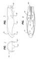
- FIG. 1illustrates a perspective view of preferred implementation of an endoscopic vessel harvesting device of the present invention.
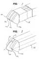
- FIG. 2illustrates an enlarged front view of the headpiece of the endoscopic vessel harvesting device of FIG. 1 .
- FIG. 3illustrates an enlarged side view of the headpiece of the endoscopic harvesting device of FIG. 1
- FIG. 4illustrates an enlarged bottom view of the headpiece of the endoscopic harvesting device of FIG. 1 .
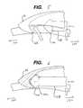
- FIG. 5illustrates an enlarged side view of a distal end of the headpiece for the endoscopic harvesting device of FIG. 1 in which a plunger is being extended.
- FIG. 6illustrates an enlarged side view of a distal end of the headpiece for the endoscopic harvesting device of FIG. 1 in which a knife is extended from the plunger.
- FIG. 7illustrates an enlarged view of a plunger with the knife retracted.
- FIG. 8illustrates an enlarged view of a plunger with the knife extended.
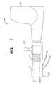
- FIG. 9illustrates a cross sectional view of the actuator and handle of the device of FIG. 1 .
- FIG. 10illustrates an enlarged front view of an alternative headpiece having a movable hook.
- FIG. 11illustrates an enlarged sectional side view of the headpiece of FIG. 10 having the movable hook extended.
- FIG. 12illustrates an enlarged bottom view of FIG. 11 .
- FIG. 13illustrates an enlarged side view of the headpiece of FIG. 11 having the movable hook retracted.
- FIG. 14illustrates an enlarged side view of the actuator of FIG. 1, showing the position of the components of the actuator when the plunger is retracted.
- FIG. 15illustrates an enlarged side view of the actuator of FIG. 1, showing the position of the components of the actuator when the plunger is extended.
- FIG. 16illustrates an enlarged side view of the actuator of FIG. 1, showing the position of the components of the actuator when the knife is extended.
- an endoscopic vessel harvesting devicefor the removal of vessels from a body is illustrated therein, generally referred to by reference number 100 .
- the EVH 100is often used for the removal of the saphenous vein from the leg of a patient undergoing a CABG operation.
- the embodiments discussed hereinare directed to the removal of such saphenous veins, however, it should be noted that they are not limited to the removal of saphenous veins and could be utilized for the removal of any vessel from a patient.
- traditional procedures for removing the saphenous veinrequired the exchange of various tools multiple times for each side branch ligation and transection.
- the vessel harvesting device (EVH) 100is comprised of a shaft 110 , the shaft is used to house an endoscope 116 inserted therein.
- the shaft 110is preferably formed of a medical grade material, such as stainless steel.
- the headpiece 112is preferably formed of a medical grade transparent material such as, polycarbonate.
- the headpiece 112is used for dissection of a vessel from the surrounding tissue.
- the headpiece 112defines a workspace 127 , which can be viewed through an endoscope 116 inserted into the shaft 110 to which the headpiece 112 is attached.
- a hook 126is preferably located on a distal end 161 of the headpiece 112 .
- the hook 126is angled toward the proximate end 151 of the EVH 100 .
- the hook 126assists in the dissection of vessels and is used in the compression, ligation and transection of the dissected vessel.
- the headpiece 112On the sides of the headpiece 112 there are extensions 130 which extend downward and towards the center of the device, as can be seen in FIG. 4 . As will be discussed below, these extensions 130 assist in the dissection of vessels.
- a handle 114on a proximal end 151 of the EVH 100 there is disposed a handle 114 .
- the handle 114is preferably formed of a thermoplastic. The handle is used to manipulate the EVH 100 .
- the handle 114also preferably provides an insertion point for.the endoscope and may house various controls.
- a plunger 118is disposed on the distal end 161 of shaft 110 and is movable from a retracted position to an extended position within the workspace 127 .
- the plunger 118interacts with a portion of the headpiece 112 .
- the portionis an integrally formed hook 126 .
- the plunger 118is extendable in the direction of hook 126 , and this movement facilitates the capture of vessels between the plunger 118 and the hook 126 .
- the EVH 100preferably comprises a ligation means.
- the ligation meansis preferably located on the plunger 118 as shown in FIG. 7 .
- the ligation meansis preferably a pair of electrodes 144 which can be energized with RF energy to cauterize a vessel captured between the plunger 118 and the hook 126 .
- the EVH 100preferably comprises a transection means.
- the transection meansis preferably housed in the plunger 118 as shown in FIG. 8 .
- the preferred transection meansis a knife 140 housed between the electrodes 144 .
- the knife 140is used to cut a vessel captured between the plunger 118 and the hook 126 and cauterized by the electrodes 144 .
- the plunger 118is preferably formed of two electrodes 144 of opposite polarities, separated from one another by at least one insulator 142 , as shown in FIG. 7 .
- the electrodesare preferably formed of a medical grade stainless steel and are electrically connected to an RF generator as is known in the art.
- the electrodesare energized by either controls (not shown) located in the handle 114 , or by a foot pedal (also not shown) as is commonly used in the art, and shown in FIG. 1 .
- a knife 140is disposed between the two insulators 142 , and the electrodes 144 are separated from the.insulators 142 to isolate them from each other electrically and/or the knife 140 .
- the knife 140is formed of a medical grade material, such as a stainless steel hardened to maintain a sharp edge for the life of the device.
- the insulators 142are preferable formed of a medical grade insulating material such as, but not limited to polycarbonate and polyethylene, in of a thickness in the range of about 1-2 mm.
- the electrodesare preferably offset from one another by the insulators 142 and the knife 140 a distance 2.5 mm. This minimizes the collateral damage done to the vessel and the surrounding tissue.
- the knife 140can serve as an electrode of one polarity and the two electrodes 144 can serve as a single electrode of a second polarity.
- the EVH 100also includes an actuator 120 for the actuation of the plunger 118 .
- the actuator 120is preferably disposed on the proximal end 151 of the shaft 110 .
- the actuator 120is comprised of a control knob 122 , a biasing means 124 , a carriage 125 (shown in FIGS. 14 - 16 ), and a stop 132 .
- the control knob 122is connected to the plunger 118 .
- the biasing means 124may be a spring 124 , as shown in FIG. 9, and acts upon the stop 132 to return the control knob 122 to a certain position.
- a plastic sheath 111formed preferably of a polycarbonate.
- the sheath 111provides a housing for a slot 146 in which the plunger 118 is slidably housed, and may also provide a second slot (not shown) for a control rod 244 , when used with a slidable hook 226 configuration, as shown in FIG. 14, and discussed below.
- the plunger 118extends from the actuator 120 to the headpiece 112 , and is housed in a slot 146 .
- the control knob 122in connection with a carriage 125 , is used to move the plunger 118 from a retracted to an extended position.
- FIG. 3shows the plunger 118 in a retracted position.
- the control knob 122is independently connected to the plunger 118 and a knife 140 housed therein.
- the control knob 122slides along a portion of the shaft 110 in a carriage 125 , as shown in FIG. 14 .
- the control knob 122is prevented from moving in the carriage 125 by the biasing means 124 .
- the carriage 125is connected to the plunger 118 . Therefore a movement of the carriage 125 results in a corresponding movement of the plunger 118 .
- any force applied by the user on the control knob 122causes the biasing means 124 to compress, as shown in FIG. 15 .
- This compression of the biasing means 124allows the control knob 122 to move independently of the carriage 125 .
- the knife 140is connected to the control knob 122 and any further movement of the control knob 122 results in movement of the knife 140 , as shown in FIG. 16 . Since the knife 140 is slidable between the two insulators 142 , additional movement of the control knob 122 after the carriage 125 has meet the stop 132 allows the knife 140 to extend beyond the end of the plunger 118 , as shown in FIG. 9, because the knife 140 is slidable between the two insulators 142 . When in the retracted position, the biasing means maintains the knife 140 in a position between the two insulators. This insures that the knife 140 will not inadvertently cut tissue which comes in contact with the headpiece.
- the knife 140Upon subsequent release of the control knob 122 , the knife 140 is retracted into the plunger 118 by the force of the biasing means as shown in FIG. 10 .
- the biasing means 124preferably does not move the plunger 118 in relation to the hook 126 , as can be seen in a comparison of FIGS. 15 and 16. Movement of the plunger 118 is performed by movement of the control knob 122 in the proximal direction 150 by the user which acts on the carriage 125 to move the plunger 118 , as shown in FIG. 14 .
- the capture, ligation and transection of a side branch vesselis as performed as follows.
- the operator of EVH 100hooks a side branch vessel with the hook 126 , as shown in FIG. 5 .
- the plunger 118is extended compressing the vessel between the plunger 118 and the hook 126 , as shown in FIG. 6 .
- the electrodes 144are then energized with RF energy, cauterizing the vessel.
- the knife 140is extended, cutting the cauterized vessel.
- the portion of the headpiece which interacts with the plungercomprises a hook 226 which is slidably engaged with the headpiece 212 .
- the hook 226is connected to a control rod 244 .
- the hook 226is formed preferably of a medical grade thermoplastic or elastomer.
- the control rod 244is actuated by an actuation means (not shown). Since it is preferable that the control rod is flexible to conform to the shape of the head piece 212 , the control rod is preferably formed of a medical grade material, such as high density polyethylene.
- the control rod 244has a stop 242 which prevents the hook 226 from extending beyond the end of the headpiece 212 .
- the stop 242stops the movement of the control rod 244 upon coming in contact with capturing means 240 .
- the capturing means 240limits the travel of the control rod 244 , and thereby limit the travel of the hook 226 .
- the capturing means 240also prevents the control rod 244 and hook 226 assembly from entering the workspace.
- the capturing means 240insures that the control rod 244 and the hook 226 follow the contours of the headpiece 212 and do not block the field of view (F.O.V.) for the endoscope 216 , as shown in FIG. 16 .
- the slidable hook 226is also used for the ligation and transection of side branch vessels.
- the hook 226Upon discovery of a side branch vessel, the hook 226 is slid towards the distal end 161 of the headpiece 212 using the control rod 244 . Upon reaching the stop 242 the hook 226 is properly positioned, as shown in FIG. 11 .
- the hook 226is used to capture the side branch vessel and a plunger 218 is extended.
- the devicepreferably comprises similar ligation and transection means as that described above, and their descriptions are therefore not reiterated here. After transection, the hook 226 can then be retracted as shown in FIG. 13, to insure that it is not impeding the F.O.V. of the endoscope.
- the traditional method for the removal of the saphenous veinis well known in the art.
- an incisionis made in the patients leg.
- the incisionis typically three or four cm in length and provides access to the vessel.
- the vesselis surrounded by tissue from which it must be dissected. This is accomplished using the edge of the headpiece of the harvesting device. This allows the vessel to be accessed by the harvesting device and through the dissection the head provides a workspace to continue the dissection and proceed with removal of the vessel.
- the surgeonwill uncover numerous side branch vessels which are attached to the saphenous vein. Each of these side branch vessels must be individually dissected, ligated and transected so that the saphenous vein may be removed.
- the methodincludes the steps of locating the vessel to be removed, making an incision, and inserting the EVH 100 into the incision.
- the blunt dissection of the vesselis performed by moving the headpiece 112 of the EVH 100 along the vessel. This separates the vessel from tissue above the vessel and exposes the vessel to the EVH 100 .
- a workspace 127is defined by the headpiece 112 .
- the workspaceprovides a location for the plunger 118 to be operated, shown in FIGS. 5, 6 , and 11 .
- the vesselwill undoubtedly have a number of side branch vessels connected to it. Each of these will have to be individually ligated and transected before removal of the vessel.
- the headpiece 112can be placed over the side branch as shown in FIG. 5 .
- the EVH 100can be drawn back towards the operator so that the vessel can be captured by the hook 126 , as shown if FIG. 5 .
- the plunger 118is moved in the distal direction 160 by moving control knob 122 towards the distal end 161 of the EVH 100 .
- the vesselis captured, as shown in FIG. 6 .
- the hook 226is first extended before the vessel is captured.
- the captured vesselis then compressed by the pressure applied by the plunger in the distal 160 direction.
- the side branch vesselis sandwiched between the hook and the plunger 118 .
- the plunger vessel 118may also be fitted with transection and ligation means, as show in FIGS. 7 and 8. These means are actuated by the operator using their respective controls.
- the surgeoncan actuate the ligation means, which are preferably a pair of electrodes, by energizing the electrodes 144 with RF energy via a switch (not shown) located in the handle 114 of the EVH 100 or by using a foot pedal (not shown) as is common in the art.
- RF energycan be supplied to the electrodes 144 . This effectively ligates the side branch vessel by cauterization.
- the side branch vesselcan be transected.
- the side branch vesselcan be transected using a knife edge 140 located in the plunger 118 between the insulators 142 , as shown in FIG. 8 .
- This knife 140is actuated by moving control knob 122 in the carriage 125 in the distal 160 direction to overcome the force of the biasing means 124 , as shown in FIGS. 14-16. This movement exposes the knife 140 and transects the compressed and cauterized side branch captured between the plunger 118 and the hook 126 .
- the surgeoncan proceed with the dissection of the vessel and move to the next side branch vessel requiring ligation and transection.
- the methods of the present inventiondo not require the insertion of any extraneous tools to perform the transection and ligation procedure. Nor do they require multiple tool exchanges. Accordingly, the procedure as a whole is far easier, and efficient that those previously known. As a result the stress on the patient is reduced.
- CABGcoronary artery bypass graft procedure
- a patientis prepared for cardiac surgery in a conventional manner using conventional techniques and procedures.
- the patientis then anesthetized and ventilated using conventional techniques.
- a conventional CABG procedureis performed by harvesting the greater saphenous vein from one or both of the patient's legs.
- the surgeonprepares an opening to the heart by dividing the patient's sternum (conventional median sternotomy) and spreading the rib cage apart using a surgical retractor.
- the surgeonnext begins dissecting the internal mammary artery (IMA) from the chest wall of the patient, so that the distal end of the vessel may be anastomosed to the diseased lower anterior descending (LAD) coronary artery on the distal side of a lesion on the septum near the left ventricle of the heart as a source of oxygenated blood.
- IMAinternal mammary artery
- LADdiseased lower anterior descending coronary artery
- the surgeonprepares the heart for attaching the graft vessels by cutting and pulling away the pericardium. After checking the graft vessels for patency, collateral damage and viability, the surgeon prepares to do the anastomoses necessary to bypass the lesions in the coronary arteries.
- the surgeonsutures the proximal end of each graft vessel to the patient's aorta and the distal end to the diseased coronary artery, distal to the blockage or lesion.
- the distal end of the LADis similarly anatomosed to a coronary artery distal to a lesion in a conventional manner.
- the surgeonchecks the bypass grafts for adequate blood flow in a conventional manner, and then completes the remainder of the operation in a conventional manner.
- the veins used in the CABG procedureare harvested endoscopically using the vein harvesting instruments of the present invention.
- the patient's legis positioned to be slightly bent and is turned to expose the inner leg.
- a markeris used to show on the skin the location of the vein to be harvested.
- an incisionis created on the inner leg near the knee, through the skin and subcutaneous layers.
- the veintypically lies directly beneath the subcutaneous layers and so a middle portion of the vein is accessed through the incision.
- a surgical instrumentis introduced into the incision.
- An endoscopeprovides visualization of the vein and surrounding tissue within the working space inside the head. The instrument is advanced along the vein.
Landscapes
- Health & Medical Sciences (AREA)
- Surgery (AREA)
- Life Sciences & Earth Sciences (AREA)
- Engineering & Computer Science (AREA)
- Biomedical Technology (AREA)
- Public Health (AREA)
- Nuclear Medicine, Radiotherapy & Molecular Imaging (AREA)
- Veterinary Medicine (AREA)
- General Health & Medical Sciences (AREA)
- Heart & Thoracic Surgery (AREA)
- Medical Informatics (AREA)
- Molecular Biology (AREA)
- Animal Behavior & Ethology (AREA)
- Physics & Mathematics (AREA)
- Otolaryngology (AREA)
- Plasma & Fusion (AREA)
- Rheumatology (AREA)
- Surgical Instruments (AREA)
Abstract
Description
Claims (17)
Priority Applications (2)
| Application Number | Priority Date | Filing Date | Title |
|---|---|---|---|
| US09/966,858US6592582B2 (en) | 2001-09-28 | 2001-09-28 | Vessel harvesting retractor with electrosurgical plunger |
| US10/612,363US20040097921A1 (en) | 2001-09-28 | 2003-07-02 | Vessel harvesting retractor with electrosurgical plunger |
Applications Claiming Priority (1)
| Application Number | Priority Date | Filing Date | Title |
|---|---|---|---|
| US09/966,858US6592582B2 (en) | 2001-09-28 | 2001-09-28 | Vessel harvesting retractor with electrosurgical plunger |
Related Child Applications (1)
| Application Number | Title | Priority Date | Filing Date |
|---|---|---|---|
| US10/612,363ContinuationUS20040097921A1 (en) | 2001-09-28 | 2003-07-02 | Vessel harvesting retractor with electrosurgical plunger |
Publications (2)
| Publication Number | Publication Date |
|---|---|
| US20030065323A1 US20030065323A1 (en) | 2003-04-03 |
| US6592582B2true US6592582B2 (en) | 2003-07-15 |
Family
ID=25511956
Family Applications (2)
| Application Number | Title | Priority Date | Filing Date |
|---|---|---|---|
| US09/966,858Expired - Fee RelatedUS6592582B2 (en) | 2001-09-28 | 2001-09-28 | Vessel harvesting retractor with electrosurgical plunger |
| US10/612,363AbandonedUS20040097921A1 (en) | 2001-09-28 | 2003-07-02 | Vessel harvesting retractor with electrosurgical plunger |
Family Applications After (1)
| Application Number | Title | Priority Date | Filing Date |
|---|---|---|---|
| US10/612,363AbandonedUS20040097921A1 (en) | 2001-09-28 | 2003-07-02 | Vessel harvesting retractor with electrosurgical plunger |
Country Status (1)
| Country | Link |
|---|---|
| US (2) | US6592582B2 (en) |
Cited By (34)
| Publication number | Priority date | Publication date | Assignee | Title |
|---|---|---|---|---|
| US20030130654A1 (en)* | 2001-12-28 | 2003-07-10 | Olympus Optical Co., Ltd. | Treatment device for cutting living tissue |
| US20040204725A1 (en)* | 2001-06-26 | 2004-10-14 | Bayer Hanspeter Robert | Conduit harvesting instrument and method |
| US20060030844A1 (en)* | 2004-08-04 | 2006-02-09 | Knight Bradley P | Transparent electrode for the radiofrequency ablation of tissue |
| US20060074444A1 (en)* | 2004-09-28 | 2006-04-06 | Lin Arthur M | Modular vessel harvesting system and method |
| US20060211916A1 (en)* | 2001-12-28 | 2006-09-21 | Olympus Corporation | Living tissue harvesting apparatus |
| US20070021655A1 (en)* | 2005-07-15 | 2007-01-25 | Dr. Ayoub Sayeg | Method and instruments for breast augmentation mammaplasty |
| US20070156023A1 (en)* | 2006-01-05 | 2007-07-05 | Depuy Spine, Inc. | Non-rigid surgical retractor |
| US20080255600A1 (en)* | 2005-02-10 | 2008-10-16 | Medical Device Innovations Ltd. | Endoscopic Dissector |
| US20090018400A1 (en)* | 2003-12-18 | 2009-01-15 | Depuy Spine, Inc. | Surgical retractor systems and illuminated cannulae |
| US7758501B2 (en) | 2006-01-04 | 2010-07-20 | Depuy Spine, Inc. | Surgical reactors and methods of minimally invasive surgery |
| US20110046624A1 (en)* | 2009-08-21 | 2011-02-24 | Maquet Cardiovascular Llc | Single handled endoscopic vessel harvesting system with rotation control |
| US7918792B2 (en) | 2006-01-04 | 2011-04-05 | Depuy Spine, Inc. | Surgical retractor for use with minimally invasive spinal stabilization systems and methods of minimally invasive surgery |
| US20110172688A1 (en)* | 2010-01-11 | 2011-07-14 | Tyco Healthcare Group Lp | Conduit Harvesting Instrument and Method |
| US7981031B2 (en) | 2006-01-04 | 2011-07-19 | Depuy Spine, Inc. | Surgical access devices and methods of minimally invasive surgery |
| US20120239086A1 (en)* | 2011-03-14 | 2012-09-20 | Reznik Alan M | Nonlinear self seating suture anchor for confined spaces |
| US8551088B2 (en) | 2008-03-31 | 2013-10-08 | Applied Medical Resources Corporation | Electrosurgical system |
| US9039694B2 (en) | 2010-10-22 | 2015-05-26 | Just Right Surgical, Llc | RF generator system for surgical vessel sealing |
| US9144455B2 (en) | 2010-06-07 | 2015-09-29 | Just Right Surgical, Llc | Low power tissue sealing device and method |
| USD748259S1 (en) | 2014-12-29 | 2016-01-26 | Applied Medical Resources Corporation | Electrosurgical instrument |
| US9320563B2 (en) | 2010-10-01 | 2016-04-26 | Applied Medical Resources Corporation | Electrosurgical instruments and connections thereto |
| US20170347996A1 (en)* | 2006-06-01 | 2017-12-07 | Maquet Cardiovascular Llc | Endoscopic vessel harvesting system components |
| US10064611B2 (en) | 2015-07-22 | 2018-09-04 | Covidien Lp | Methods and devices for vein harvesting |
| US10149713B2 (en) | 2014-05-16 | 2018-12-11 | Applied Medical Resources Corporation | Electrosurgical system |
| US20190150902A1 (en)* | 2010-04-23 | 2019-05-23 | W.O.M. World Of Medicine Gmbh | Invasive instrument for treating vessels |
| US10420603B2 (en) | 2014-12-23 | 2019-09-24 | Applied Medical Resources Corporation | Bipolar electrosurgical sealer and divider |
| US10575835B2 (en) | 2014-10-14 | 2020-03-03 | Covidien Lp | Methods and devices for vein harvesting |
| US10646210B2 (en) | 2014-10-14 | 2020-05-12 | Covidien Lp | Methods and devices for vein harvesting |
| US10792092B2 (en) | 2014-05-30 | 2020-10-06 | Applied Medical Resources Corporation | Electrosurgical seal and dissection systems |
| USD904611S1 (en) | 2018-10-10 | 2020-12-08 | Bolder Surgical, Llc | Jaw design for a surgical instrument |
| USD934423S1 (en) | 2020-09-11 | 2021-10-26 | Bolder Surgical, Llc | End effector for a surgical device |
| US11547466B2 (en) | 2018-06-20 | 2023-01-10 | Covidien Lp | Visualization devices and methods for use in surgical procedures |
| US11696796B2 (en) | 2018-11-16 | 2023-07-11 | Applied Medical Resources Corporation | Electrosurgical system |
| US11864812B2 (en) | 2018-09-05 | 2024-01-09 | Applied Medical Resources Corporation | Electrosurgical generator control system |
| USD1046129S1 (en) | 2021-04-14 | 2024-10-08 | Bolder Surgical, Llc | End effector for a surgical instrument |
Families Citing this family (10)
| Publication number | Priority date | Publication date | Assignee | Title |
|---|---|---|---|---|
| US7138316B2 (en)* | 2003-09-23 | 2006-11-21 | Intel Corporation | Semiconductor channel on insulator structure |
| US20050096646A1 (en)* | 2003-10-31 | 2005-05-05 | Parris Wellman | Surgical system for retracting and severing tissue |
| US7314479B2 (en) | 2003-10-31 | 2008-01-01 | Parris Wellman | Space-creating retractor with vessel manipulator |
| US20060173474A1 (en)* | 2003-10-31 | 2006-08-03 | Parris Wellman | Surgical device having a track to guide an actuator |
| US7275875B1 (en)* | 2003-10-31 | 2007-10-02 | Stryker Corporation | Universal interface for single-handed insertion of cables |
| US20050096671A1 (en)* | 2003-10-31 | 2005-05-05 | Parris Wellman | Control mechanism for a surgical instrument |
| US20050096670A1 (en)* | 2003-10-31 | 2005-05-05 | Parris Wellman | Surgical end effector |
| US8992424B2 (en)* | 2007-02-09 | 2015-03-31 | Skeletal Dynamics Llc | Endo-surgical device and method |
| WO2016117151A1 (en) | 2015-01-19 | 2016-07-28 | テルモ株式会社 | Blood vessel removal device |
| JP6605989B2 (en)* | 2016-02-29 | 2019-11-13 | テルモ株式会社 | Processing device |
Citations (32)
| Publication number | Priority date | Publication date | Assignee | Title |
|---|---|---|---|---|
| US5366476A (en)* | 1993-04-02 | 1994-11-22 | Laparomed Corporation | Handle for laparoscopic instrument |
| US5591183A (en) | 1995-04-12 | 1997-01-07 | Origin Medsystems, Inc. | Dissection apparatus |
| US5593418A (en) | 1995-05-19 | 1997-01-14 | General Surgical Innovations, Inc. | Methods and devices for harvesting blood vessels with balloons |
| US5601581A (en) | 1995-05-19 | 1997-02-11 | General Surgical Innovations, Inc. | Methods and devices for blood vessel harvesting |
| US5667480A (en) | 1995-10-20 | 1997-09-16 | Ethicon Endo-Surgery, Inc. | Method and devices for endoscopic vessel harvesting |
| US5695514A (en) | 1995-07-13 | 1997-12-09 | Guidant Corporation | Method and apparatus for harvesting blood vessels |
| US5817013A (en) | 1996-03-19 | 1998-10-06 | Enable Medical Corporation | Method and apparatus for the minimally invasive harvesting of a saphenous vein and the like |
| US5836945A (en) | 1997-02-20 | 1998-11-17 | Perkins; Rodney C. | Biological vessel harvesting device |
| USRE36043E (en) | 1992-10-02 | 1999-01-12 | Embro Vascular, L.L.C. | Endoscope and method for vein removal |
| US5873889A (en) | 1997-08-08 | 1999-02-23 | Origin Medsystems, Inc. | Tissue separation cannula with dissection probe and method |
| US5891140A (en) | 1996-12-23 | 1999-04-06 | Cardiothoracic Systems, Inc. | Electrosurgical device for harvesting a vessel especially the internal mammary artery for coronary artery bypass grafting |
| US5916233A (en) | 1998-03-05 | 1999-06-29 | Origin Medsystems, Inc. | Vessel harvesting method and instrument including access port |
| US5922004A (en) | 1997-08-28 | 1999-07-13 | Ethicon Endo-Surgery, Inc. | Method for performing optical tissue dissection/retraction |
| US5928138A (en) | 1996-08-15 | 1999-07-27 | Ethicon Endo-Surgery, Inc. | Method and devices for endoscopic vessel harvesting |
| US5938680A (en) | 1997-06-19 | 1999-08-17 | Cardiothoracic Systems, Inc. | Devices and methods for harvesting vascular conduits |
| US5968066A (en) | 1994-06-29 | 1999-10-19 | General Surgical Innovations, Inc. | Methods and devices for blood vessel harvesting |
| US5968065A (en) | 1995-07-13 | 1999-10-19 | Origin Medsystems, Inc. | Tissue separation cannula |
| US5972010A (en) | 1998-05-14 | 1999-10-26 | Taheri; Syde A. | Vein harvesting system |
| US5970982A (en) | 1997-02-20 | 1999-10-26 | Perkins; Rodney C. | Minimally invasive biological vessel harvesting method |
| US5976168A (en) | 1995-07-13 | 1999-11-02 | Origin Medsystems, Inc. | Tissue separation cannula |
| US5984937A (en) | 1997-03-31 | 1999-11-16 | Origin Medsystems, Inc. | Orbital dissection cannula and method |
| WO1999066842A1 (en) | 1998-06-19 | 1999-12-29 | Karl Storz Gmbh & Co. | Medical instrument for endoscopic removal of the vena saphena magna |
| US6019771A (en) | 1996-12-02 | 2000-02-01 | Cardiothoracic Systems, Inc. | Devices and methods for minimally invasive harvesting of a vessel especially the saphenous vein for coronary bypass grafting |
| EP0979635A2 (en) | 1998-08-12 | 2000-02-16 | Origin Medsystems, Inc. | Tissue dissector apparatus |
| US6036713A (en) | 1996-01-24 | 2000-03-14 | Archimedes Surgical, Inc. | Instruments and methods for minimally invasive vascular procedures |
| WO2000015116A1 (en) | 1998-09-10 | 2000-03-23 | General Surgical Innovations, Inc. | Direct vision subcutaneous tissue retractor |
| US6042538A (en) | 1998-11-18 | 2000-03-28 | Emory University | Device for endoscopic vessel harvesting |
| US6059802A (en) | 1998-02-27 | 2000-05-09 | Cardiothoracic Systems, Inc. | Dissecting retractor for harvesting vessels |
| US6071232A (en) | 1995-12-11 | 2000-06-06 | Embro Vascular L.L.C. | Apparatus for vein removal |
| US6080102A (en)* | 1995-07-07 | 2000-06-27 | Olympus Optical Co., Ltd. | System for evulsing subcutaneous tissue |
| US6120434A (en) | 1994-08-29 | 2000-09-19 | Olympus Optical Co., Ltd. | Method of securing a cavity using a rigid sheath with transparent cap |
| US6139489A (en) | 1999-10-05 | 2000-10-31 | Ethicon Endo-Surgery, Inc. | Surgical device with integrally mounted image sensor |
Family Cites Families (5)
| Publication number | Priority date | Publication date | Assignee | Title |
|---|---|---|---|---|
| US5190541A (en)* | 1990-10-17 | 1993-03-02 | Boston Scientific Corporation | Surgical instrument and method |
| JPH06505654A (en)* | 1991-02-06 | 1994-06-30 | ラパロームド コーポレイション | electrosurgical device |
| US5176695A (en)* | 1991-07-08 | 1993-01-05 | Davinci Medical, Inc. | Surgical cutting means |
| US5549623A (en)* | 1991-11-18 | 1996-08-27 | Dexide, Inc. | Endodissector surgical instrument |
| US5397333A (en)* | 1993-09-24 | 1995-03-14 | Nusurg Medical, Inc. | Surgical hook knife |
- 2001
- 2001-09-28USUS09/966,858patent/US6592582B2/ennot_activeExpired - Fee Related
- 2003
- 2003-07-02USUS10/612,363patent/US20040097921A1/ennot_activeAbandoned
Patent Citations (44)
| Publication number | Priority date | Publication date | Assignee | Title |
|---|---|---|---|---|
| USRE36043E (en) | 1992-10-02 | 1999-01-12 | Embro Vascular, L.L.C. | Endoscope and method for vein removal |
| US5366476A (en)* | 1993-04-02 | 1994-11-22 | Laparomed Corporation | Handle for laparoscopic instrument |
| US5968066A (en) | 1994-06-29 | 1999-10-19 | General Surgical Innovations, Inc. | Methods and devices for blood vessel harvesting |
| US6120434A (en) | 1994-08-29 | 2000-09-19 | Olympus Optical Co., Ltd. | Method of securing a cavity using a rigid sheath with transparent cap |
| US5591183A (en) | 1995-04-12 | 1997-01-07 | Origin Medsystems, Inc. | Dissection apparatus |
| US5601581A (en) | 1995-05-19 | 1997-02-11 | General Surgical Innovations, Inc. | Methods and devices for blood vessel harvesting |
| US6068639A (en) | 1995-05-19 | 2000-05-30 | General Surgical Innovations, Inc. | Methods and devices for blood vessel harvesting |
| US5730748A (en) | 1995-05-19 | 1998-03-24 | General Surgical Innovations, Inc. | Methods and devices for blood vessel harvesting |
| US5797947A (en) | 1995-05-19 | 1998-08-25 | General Surgical Innovations, Inc. | Methods and devices for harvesting blood vessels with balloons |
| US5902316A (en) | 1995-05-19 | 1999-05-11 | General Surgical Innovations, Inc. | Methods and devices for harvesting blood vessels with balloons |
| US5899913A (en) | 1995-05-19 | 1999-05-04 | General Surgical Innovations, Inc. | Methods and devices for blood vessel harvesting |
| US5853417A (en) | 1995-05-19 | 1998-12-29 | General Surgical Innovations, Inc. | Methods and devices for blood vessel harvesting |
| US5876413A (en) | 1995-05-19 | 1999-03-02 | General Surgical Innovations, Inc. | Methods and devices for blood vessel harvesting |
| US5593418A (en) | 1995-05-19 | 1997-01-14 | General Surgical Innovations, Inc. | Methods and devices for harvesting blood vessels with balloons |
| US6080102A (en)* | 1995-07-07 | 2000-06-27 | Olympus Optical Co., Ltd. | System for evulsing subcutaneous tissue |
| US5968065A (en) | 1995-07-13 | 1999-10-19 | Origin Medsystems, Inc. | Tissue separation cannula |
| US5980549A (en) | 1995-07-13 | 1999-11-09 | Origin Medsystems, Inc. | Tissue separation cannula with dissection probe and method |
| US5976168A (en) | 1995-07-13 | 1999-11-02 | Origin Medsystems, Inc. | Tissue separation cannula |
| US6036714A (en) | 1995-07-13 | 2000-03-14 | Origin Medsystems, Inc. | Tissue separation method |
| US5695514A (en) | 1995-07-13 | 1997-12-09 | Guidant Corporation | Method and apparatus for harvesting blood vessels |
| US5722934A (en) | 1995-10-20 | 1998-03-03 | Ethicon Endo-Surgery, Inc. | Method and devices for endoscopoic vessel harvesting |
| US5725479A (en) | 1995-10-20 | 1998-03-10 | Ethicon Endo-Surgery, Inc. | Method and devices for endoscopic vessel harvesting |
| US5667480A (en) | 1995-10-20 | 1997-09-16 | Ethicon Endo-Surgery, Inc. | Method and devices for endoscopic vessel harvesting |
| US6071232A (en) | 1995-12-11 | 2000-06-06 | Embro Vascular L.L.C. | Apparatus for vein removal |
| US6036713A (en) | 1996-01-24 | 2000-03-14 | Archimedes Surgical, Inc. | Instruments and methods for minimally invasive vascular procedures |
| US5817013A (en) | 1996-03-19 | 1998-10-06 | Enable Medical Corporation | Method and apparatus for the minimally invasive harvesting of a saphenous vein and the like |
| US6022313A (en) | 1996-03-19 | 2000-02-08 | Cardiothoracic Systems, Inc. | Method and apparatus for the minimally invasive harvesting of a saphenous vein and the like |
| US5928138A (en) | 1996-08-15 | 1999-07-27 | Ethicon Endo-Surgery, Inc. | Method and devices for endoscopic vessel harvesting |
| US6019771A (en) | 1996-12-02 | 2000-02-01 | Cardiothoracic Systems, Inc. | Devices and methods for minimally invasive harvesting of a vessel especially the saphenous vein for coronary bypass grafting |
| US5891140A (en) | 1996-12-23 | 1999-04-06 | Cardiothoracic Systems, Inc. | Electrosurgical device for harvesting a vessel especially the internal mammary artery for coronary artery bypass grafting |
| US5970982A (en) | 1997-02-20 | 1999-10-26 | Perkins; Rodney C. | Minimally invasive biological vessel harvesting method |
| US5836945A (en) | 1997-02-20 | 1998-11-17 | Perkins; Rodney C. | Biological vessel harvesting device |
| US5984937A (en) | 1997-03-31 | 1999-11-16 | Origin Medsystems, Inc. | Orbital dissection cannula and method |
| US5938680A (en) | 1997-06-19 | 1999-08-17 | Cardiothoracic Systems, Inc. | Devices and methods for harvesting vascular conduits |
| US5873889A (en) | 1997-08-08 | 1999-02-23 | Origin Medsystems, Inc. | Tissue separation cannula with dissection probe and method |
| US5922004A (en) | 1997-08-28 | 1999-07-13 | Ethicon Endo-Surgery, Inc. | Method for performing optical tissue dissection/retraction |
| US6059802A (en) | 1998-02-27 | 2000-05-09 | Cardiothoracic Systems, Inc. | Dissecting retractor for harvesting vessels |
| US5916233A (en) | 1998-03-05 | 1999-06-29 | Origin Medsystems, Inc. | Vessel harvesting method and instrument including access port |
| US5972010A (en) | 1998-05-14 | 1999-10-26 | Taheri; Syde A. | Vein harvesting system |
| WO1999066842A1 (en) | 1998-06-19 | 1999-12-29 | Karl Storz Gmbh & Co. | Medical instrument for endoscopic removal of the vena saphena magna |
| EP0979635A2 (en) | 1998-08-12 | 2000-02-16 | Origin Medsystems, Inc. | Tissue dissector apparatus |
| WO2000015116A1 (en) | 1998-09-10 | 2000-03-23 | General Surgical Innovations, Inc. | Direct vision subcutaneous tissue retractor |
| US6042538A (en) | 1998-11-18 | 2000-03-28 | Emory University | Device for endoscopic vessel harvesting |
| US6139489A (en) | 1999-10-05 | 2000-10-31 | Ethicon Endo-Surgery, Inc. | Surgical device with integrally mounted image sensor |
Cited By (76)
| Publication number | Priority date | Publication date | Assignee | Title |
|---|---|---|---|---|
| US20040204725A1 (en)* | 2001-06-26 | 2004-10-14 | Bayer Hanspeter Robert | Conduit harvesting instrument and method |
| US7699861B2 (en) | 2001-06-26 | 2010-04-20 | Tyco Healthcare Group Lp | Conduit harvesting instrument and method |
| US7645289B2 (en) | 2001-06-26 | 2010-01-12 | Tyco Healthcare Group Lp | Conduit harvesting instrument and method |
| US7316683B2 (en)* | 2001-12-28 | 2008-01-08 | Olympus Corporation | Treatment device for cutting living tissue |
| US20030130654A1 (en)* | 2001-12-28 | 2003-07-10 | Olympus Optical Co., Ltd. | Treatment device for cutting living tissue |
| US20060211916A1 (en)* | 2001-12-28 | 2006-09-21 | Olympus Corporation | Living tissue harvesting apparatus |
| US8038611B2 (en) | 2003-12-18 | 2011-10-18 | Depuy Spine, Inc. | Surgical methods and surgical kits |
| US8622897B2 (en) | 2003-12-18 | 2014-01-07 | DePuy Synthes Products, LLC | Surgical methods and surgical kits |
| US10869657B2 (en) | 2003-12-18 | 2020-12-22 | DePuy Synthes Products, Inc. | Surgical retractor systems and illuminated cannulae |
| US20090018400A1 (en)* | 2003-12-18 | 2009-01-15 | Depuy Spine, Inc. | Surgical retractor systems and illuminated cannulae |
| US8602984B2 (en) | 2003-12-18 | 2013-12-10 | DePuy Synthes Products, LLC | Surgical retractor systems and illuminated cannulae |
| US7527625B2 (en)* | 2004-08-04 | 2009-05-05 | Olympus Corporation | Transparent electrode for the radiofrequency ablation of tissue |
| US20060030844A1 (en)* | 2004-08-04 | 2006-02-09 | Knight Bradley P | Transparent electrode for the radiofrequency ablation of tissue |
| US20060074444A1 (en)* | 2004-09-28 | 2006-04-06 | Lin Arthur M | Modular vessel harvesting system and method |
| US7887558B2 (en)* | 2004-09-28 | 2011-02-15 | Maquet Cardiovascular Llc | Modular vessel harvesting system and method |
| US8906048B2 (en) | 2004-09-28 | 2014-12-09 | Maquet Cardiovascular Llc | Modular vessel harvesting system and method |
| US8721527B2 (en)* | 2005-02-10 | 2014-05-13 | Medical Device Innovations Ltd. | Endoscopic dissector |
| US20080255600A1 (en)* | 2005-02-10 | 2008-10-16 | Medical Device Innovations Ltd. | Endoscopic Dissector |
| US20070021655A1 (en)* | 2005-07-15 | 2007-01-25 | Dr. Ayoub Sayeg | Method and instruments for breast augmentation mammaplasty |
| US7951077B2 (en)* | 2005-07-15 | 2011-05-31 | Sayeg Ayoub Dr | Method and instruments for breast augmentation mammaplasty |
| US7758501B2 (en) | 2006-01-04 | 2010-07-20 | Depuy Spine, Inc. | Surgical reactors and methods of minimally invasive surgery |
| US7981031B2 (en) | 2006-01-04 | 2011-07-19 | Depuy Spine, Inc. | Surgical access devices and methods of minimally invasive surgery |
| US8517935B2 (en) | 2006-01-04 | 2013-08-27 | DePuy Synthes Products, LLC | Surgical retractors and methods of minimally invasive surgery |
| US8550995B2 (en) | 2006-01-04 | 2013-10-08 | DePuy Synthes Products, LLC | Surgical access devices and methods of minimally invasive surgery |
| US7918792B2 (en) | 2006-01-04 | 2011-04-05 | Depuy Spine, Inc. | Surgical retractor for use with minimally invasive spinal stabilization systems and methods of minimally invasive surgery |
| US7955257B2 (en) | 2006-01-05 | 2011-06-07 | Depuy Spine, Inc. | Non-rigid surgical retractor |
| US9254126B2 (en) | 2006-01-05 | 2016-02-09 | DePuy Synthes Products, Inc. | Non-rigid surgical retractor |
| US20070156023A1 (en)* | 2006-01-05 | 2007-07-05 | Depuy Spine, Inc. | Non-rigid surgical retractor |
| US11134835B2 (en) | 2006-06-01 | 2021-10-05 | Maquet Cardiovascular Llc | Endoscopic vessel harvesting system components |
| US20170347996A1 (en)* | 2006-06-01 | 2017-12-07 | Maquet Cardiovascular Llc | Endoscopic vessel harvesting system components |
| US11141055B2 (en)* | 2006-06-01 | 2021-10-12 | Maquet Cardiovascular Llc | Endoscopic vessel harvesting system components |
| US10888371B2 (en) | 2008-03-31 | 2021-01-12 | Applied Medical Resources Corporation | Electrosurgical system |
| US8562598B2 (en) | 2008-03-31 | 2013-10-22 | Applied Medical Resources Corporation | Electrosurgical system |
| US8579894B2 (en) | 2008-03-31 | 2013-11-12 | Applied Medical Resources Corporation | Electrosurgical system |
| US8915910B2 (en) | 2008-03-31 | 2014-12-23 | Applied Medical Resources Corporation | Electrosurgical system |
| US12295642B2 (en) | 2008-03-31 | 2025-05-13 | Applied Medical Resources Corporation | Electrosurgical system |
| US10342604B2 (en) | 2008-03-31 | 2019-07-09 | Applied Medical Resources Corporation | Electrosurgical system |
| US8551088B2 (en) | 2008-03-31 | 2013-10-08 | Applied Medical Resources Corporation | Electrosurgical system |
| US8568411B2 (en) | 2008-03-31 | 2013-10-29 | Applied Medical Resources Corporation | Electrosurgical system |
| US11660136B2 (en) | 2008-03-31 | 2023-05-30 | Applied Medical Resources Corporation | Electrosurgical system |
| US9566108B2 (en) | 2008-03-31 | 2017-02-14 | Applied Medical Resources Corporation | Electrosurgical system |
| US20110046624A1 (en)* | 2009-08-21 | 2011-02-24 | Maquet Cardiovascular Llc | Single handled endoscopic vessel harvesting system with rotation control |
| US8657818B2 (en) | 2009-08-21 | 2014-02-25 | Maquet Cardiovascular Llc | Single handled endoscopic vessel harvesting system with rotation control |
| US20110172688A1 (en)* | 2010-01-11 | 2011-07-14 | Tyco Healthcare Group Lp | Conduit Harvesting Instrument and Method |
| US20190150902A1 (en)* | 2010-04-23 | 2019-05-23 | W.O.M. World Of Medicine Gmbh | Invasive instrument for treating vessels |
| US11399884B2 (en) | 2010-06-07 | 2022-08-02 | Bolder Surgical, Llc | Low power tissue sealing device and method |
| US11998260B2 (en) | 2010-06-07 | 2024-06-04 | Bolder Surgical, Llc | Low-power tissue sealing device and method |
| US10166064B2 (en) | 2010-06-07 | 2019-01-01 | Just Right Surgical, Llc | Low-power tissue sealing device and method |
| US9144455B2 (en) | 2010-06-07 | 2015-09-29 | Just Right Surgical, Llc | Low power tissue sealing device and method |
| US9962222B2 (en) | 2010-10-01 | 2018-05-08 | Applied Medical Resources Corporation | Electrosurgical instruments and connections thereto |
| US12357374B2 (en) | 2010-10-01 | 2025-07-15 | Applied Medical Resources Corporation | Electrosurgical instruments and connections thereto |
| US11864823B2 (en) | 2010-10-01 | 2024-01-09 | Applied Medical Resources Corporation | Electrosurgical instruments and connections thereto |
| US9320563B2 (en) | 2010-10-01 | 2016-04-26 | Applied Medical Resources Corporation | Electrosurgical instruments and connections thereto |
| US10874452B2 (en) | 2010-10-01 | 2020-12-29 | Applied Medical Resources Corporation | Electrosurgical instruments and connections thereto |
| US9039694B2 (en) | 2010-10-22 | 2015-05-26 | Just Right Surgical, Llc | RF generator system for surgical vessel sealing |
| US10342599B2 (en) | 2010-10-22 | 2019-07-09 | Just Right Surgical, Llc | RF generator system for surgical vessel sealing |
| US9649149B2 (en) | 2010-10-22 | 2017-05-16 | Just Right Surgical, Llc | RF generator system for surgical vessel sealing |
| US20120239086A1 (en)* | 2011-03-14 | 2012-09-20 | Reznik Alan M | Nonlinear self seating suture anchor for confined spaces |
| US10149713B2 (en) | 2014-05-16 | 2018-12-11 | Applied Medical Resources Corporation | Electrosurgical system |
| US11672589B2 (en) | 2014-05-16 | 2023-06-13 | Applied Medical Resources Corporation | Electrosurgical system |
| US10792092B2 (en) | 2014-05-30 | 2020-10-06 | Applied Medical Resources Corporation | Electrosurgical seal and dissection systems |
| US12239359B2 (en) | 2014-05-30 | 2025-03-04 | Applied Medical Resources Corporation | Electrosurgical seal and dissection systems |
| US10646210B2 (en) | 2014-10-14 | 2020-05-12 | Covidien Lp | Methods and devices for vein harvesting |
| US10575835B2 (en) | 2014-10-14 | 2020-03-03 | Covidien Lp | Methods and devices for vein harvesting |
| US11571193B2 (en) | 2014-10-14 | 2023-02-07 | Covidien LLP | Methods and devices for vein harvesting |
| US11540871B2 (en) | 2014-12-23 | 2023-01-03 | Applied Medical Resources Corporation | Bipolar electrosurgical sealer and divider |
| US10420603B2 (en) | 2014-12-23 | 2019-09-24 | Applied Medical Resources Corporation | Bipolar electrosurgical sealer and divider |
| US12029472B2 (en) | 2014-12-23 | 2024-07-09 | Applied Medical Resources Corporation | Bipolar electrosurgical sealer and divider |
| USD748259S1 (en) | 2014-12-29 | 2016-01-26 | Applied Medical Resources Corporation | Electrosurgical instrument |
| US10064611B2 (en) | 2015-07-22 | 2018-09-04 | Covidien Lp | Methods and devices for vein harvesting |
| US11547466B2 (en) | 2018-06-20 | 2023-01-10 | Covidien Lp | Visualization devices and methods for use in surgical procedures |
| US11864812B2 (en) | 2018-09-05 | 2024-01-09 | Applied Medical Resources Corporation | Electrosurgical generator control system |
| USD904611S1 (en) | 2018-10-10 | 2020-12-08 | Bolder Surgical, Llc | Jaw design for a surgical instrument |
| US11696796B2 (en) | 2018-11-16 | 2023-07-11 | Applied Medical Resources Corporation | Electrosurgical system |
| USD934423S1 (en) | 2020-09-11 | 2021-10-26 | Bolder Surgical, Llc | End effector for a surgical device |
| USD1046129S1 (en) | 2021-04-14 | 2024-10-08 | Bolder Surgical, Llc | End effector for a surgical instrument |
Also Published As
| Publication number | Publication date |
|---|---|
| US20040097921A1 (en) | 2004-05-20 |
| US20030065323A1 (en) | 2003-04-03 |
Similar Documents
| Publication | Publication Date | Title |
|---|---|---|
| US6592582B2 (en) | Vessel harvesting retractor with electrosurgical plunger | |
| US6527771B1 (en) | Surgical device for endoscopic vein harvesting | |
| US6616661B2 (en) | Surgical device for clamping, ligating, and severing tissue | |
| US6740102B2 (en) | Vessel harvesting retractor with bilateral electrosurgical ligation | |
| US6656176B2 (en) | Vessel harvesting retractor with integral electrosurgical clamping elements | |
| US5913866A (en) | Devices and methods for harvesting vascular conduits | |
| US6080175A (en) | Surgical cutting instrument and method of use | |
| US6835195B2 (en) | Surgical device for applying radio frequency energy to a portion of a captured vessel | |
| US5928138A (en) | Method and devices for endoscopic vessel harvesting | |
| US5722934A (en) | Method and devices for endoscopoic vessel harvesting | |
| US6679892B2 (en) | Surgical device for ligating and severing vessels | |
| US6660016B2 (en) | Integrated vein dissector and cauterizing apparatus for endoscopic harvesting of blood vessels | |
| US8377082B2 (en) | Methods and apparatus for making precise incisions in body vessels | |
| JPH10192295A (en) | Electrical surgery instrument and method of blood vessel collecting for vascular bypass transplantation | |
| CA2537342C (en) | Method and devices for endoscopic vessel harvesting |
Legal Events
| Date | Code | Title | Description |
|---|---|---|---|
| AS | Assignment | Owner name:ETHICON, INC., NEW JERSEY Free format text:ASSIGNMENT OF ASSIGNORS INTEREST;ASSIGNORS:HESS, CHRISTOPHER J.;CLEM, MICHAEL F.;KNIGHT, GARY W.;AND OTHERS;REEL/FRAME:012480/0643;SIGNING DATES FROM 20011206 TO 20011207 | |
| AS | Assignment | Owner name:DATASCOPE CORP., NEW JERSEY Free format text:ASSIGNMENT OF ASSIGNORS INTEREST;ASSIGNOR:ETHICON, INC.;REEL/FRAME:016987/0712 Effective date:20060103 Owner name:DATASCOPE CORP., NEW JERSEY Free format text:ASSIGNMENT OF ASSIGNORS INTEREST;ASSIGNOR:ETHICON, INC.;REEL/FRAME:016987/0727 Effective date:20060103 | |
| REMI | Maintenance fee reminder mailed | ||
| REIN | Reinstatement after maintenance fee payment confirmed | ||
| FP | Lapsed due to failure to pay maintenance fee | Effective date:20070715 | |
| FEPP | Fee payment procedure | Free format text:PETITION RELATED TO MAINTENANCE FEES GRANTED (ORIGINAL EVENT CODE: PMFG); ENTITY STATUS OF PATENT OWNER: LARGE ENTITY Free format text:PETITION RELATED TO MAINTENANCE FEES FILED (ORIGINAL EVENT CODE: PMFP); ENTITY STATUS OF PATENT OWNER: LARGE ENTITY | |
| PRDP | Patent reinstated due to the acceptance of a late maintenance fee | Effective date:20081017 | |
| FPAY | Fee payment | Year of fee payment:4 | |
| SULP | Surcharge for late payment | ||
| AS | Assignment | Owner name:DATASCOPE CORP., NEW JERSEY Free format text:ASSIGNMENT OF ASSIGNORS INTEREST;ASSIGNOR:ETHICON, INC.;REEL/FRAME:022043/0201 Effective date:20060103 | |
| AS | Assignment | Owner name:SORIN GROUP USA, INC., COLORADO Free format text:ASSIGNMENT OF ASSIGNORS INTEREST;ASSIGNOR:DATASCOPE CORP.;REEL/FRAME:023234/0482 Effective date:20090825 | |
| FPAY | Fee payment | Year of fee payment:8 | |
| REMI | Maintenance fee reminder mailed | ||
| LAPS | Lapse for failure to pay maintenance fees | ||
| STCH | Information on status: patent discontinuation | Free format text:PATENT EXPIRED DUE TO NONPAYMENT OF MAINTENANCE FEES UNDER 37 CFR 1.362 | |
| FP | Lapsed due to failure to pay maintenance fee | Effective date:20150715 |