US6592577B2 - Cooling system - Google Patents
Cooling systemDownload PDFInfo
- Publication number
- US6592577B2 US6592577B2US09/771,031US77103101AUS6592577B2US 6592577 B2US6592577 B2US 6592577B2US 77103101 AUS77103101 AUS 77103101AUS 6592577 B2US6592577 B2US 6592577B2
- Authority
- US
- United States
- Prior art keywords
- coolant
- cooling system
- catheter
- cooling
- supply line
- Prior art date
- Legal status (The legal status is an assumption and is not a legal conclusion. Google has not performed a legal analysis and makes no representation as to the accuracy of the status listed.)
- Expired - Lifetime, expires
Links
Images


Classifications
- A—HUMAN NECESSITIES
- A61—MEDICAL OR VETERINARY SCIENCE; HYGIENE
- A61B—DIAGNOSIS; SURGERY; IDENTIFICATION
- A61B18/00—Surgical instruments, devices or methods for transferring non-mechanical forms of energy to or from the body
- A61B18/02—Surgical instruments, devices or methods for transferring non-mechanical forms of energy to or from the body by cooling, e.g. cryogenic techniques
- A—HUMAN NECESSITIES
- A61—MEDICAL OR VETERINARY SCIENCE; HYGIENE
- A61B—DIAGNOSIS; SURGERY; IDENTIFICATION
- A61B17/00—Surgical instruments, devices or methods
- A61B2017/00017—Electrical control of surgical instruments
- A61B2017/00022—Sensing or detecting at the treatment site
- A61B2017/00084—Temperature
- A—HUMAN NECESSITIES
- A61—MEDICAL OR VETERINARY SCIENCE; HYGIENE
- A61B—DIAGNOSIS; SURGERY; IDENTIFICATION
- A61B17/00—Surgical instruments, devices or methods
- A61B2017/00017—Electrical control of surgical instruments
- A61B2017/00199—Electrical control of surgical instruments with a console, e.g. a control panel with a display
- A—HUMAN NECESSITIES
- A61—MEDICAL OR VETERINARY SCIENCE; HYGIENE
- A61B—DIAGNOSIS; SURGERY; IDENTIFICATION
- A61B18/00—Surgical instruments, devices or methods for transferring non-mechanical forms of energy to or from the body
- A61B18/02—Surgical instruments, devices or methods for transferring non-mechanical forms of energy to or from the body by cooling, e.g. cryogenic techniques
- A61B2018/0212—Surgical instruments, devices or methods for transferring non-mechanical forms of energy to or from the body by cooling, e.g. cryogenic techniques using an instrument inserted into a body lumen, e.g. catheter
- A—HUMAN NECESSITIES
- A61—MEDICAL OR VETERINARY SCIENCE; HYGIENE
- A61B—DIAGNOSIS; SURGERY; IDENTIFICATION
- A61B18/00—Surgical instruments, devices or methods for transferring non-mechanical forms of energy to or from the body
- A61B18/02—Surgical instruments, devices or methods for transferring non-mechanical forms of energy to or from the body by cooling, e.g. cryogenic techniques
- A61B2018/0231—Characteristics of handpieces or probes
- A61B2018/0262—Characteristics of handpieces or probes using a circulating cryogenic fluid
- A61B2018/0268—Characteristics of handpieces or probes using a circulating cryogenic fluid with restriction of flow
Definitions
- the present inventionrelates to a coolant system for a catheter or treatment wand used for cryotreatment of tissue.
- the coolant systemis of the type which connects to a catheter and pumps coolant through the catheter to chill a region of the catheter, such as the distal tip, for treating tissue.
- a number of cooled catheter systemshave been developed for treating tissue in a cardiac setting, either to cool the tissue sufficiently to stun it and allow cold mapping of the heart and/or confirmation of catheter position with respect to localized tissue lesions, or to apply a more severe level of cold to ablate tissue at the site of the catheter ending.
- the range of treatments which may be effected by a cryocatheteris comparable to the range of applications for radio frequency or thermal ablation catheters, and in particular, these instruments may be configured to achieve either small localized ball shape lesions at the tip of the catheter, or one or more elongated linear lesions extending a length of several centimeters or more along the tip.
- the latter form of lesionis commonly used to achieve conduction block across a region of the cardiac wall so as to sever an aberrant pathway over a length, preventing conduction across the region, in order change the cardiac signal path topology, for example, to eliminate a faulty pathway responsible for atrial fibrillation or a tachycardia.
- catheters of this typein common with the corresponding earlier-developed radio frequency or electrothermal ablation catheter, must meet fairly demanding limitations regarding their size, flexibility, and the factors of strength, electrical conductivity and the like which affect their safety and may give rise to failure modes in use. These constraints generally require that the catheter be no larger than several millimeters in diameter so as to pass through the vascular system of the patient to the heart. Thus, any electrodes (in the case of mapping or RF/electrothermal ablation catheters), and any coolant passages (in the case of cryocatheters) must fit within a catheter body of small size.
- coolant component of prior art cryotreatment catheterssuch as a concentrated saline solution or other liquid of suitably low freezing point and viscosity, and of suitably high thermal conductivity and heat capacity, or a liquified gas such as liquid nitrogen.
- a concentrated saline solution or other liquid of suitably low freezing point and viscosityand of suitably high thermal conductivity and heat capacity
- a liquified gassuch as liquid nitrogen.
- phase change materialas the cryogenic fluid
- arranging the cathetersuch that the phase change, e.g., from a liquid to a gas, occurs in the treatment portion of the catheter tip.
- phase changee.g., from a liquid to a gas
- Another possible approachis to employ a pressurized gas, and configure the catheter for cooling by expansion of the gas in the tip structure.
- the design of a safe and effective coolant circulation systemwhich nonetheless dependably provides sufficient cooling capacity at a remote tip remains a difficult goal.
- a coolant systemthat includes a medical device and a console connectable to the medical device at a connection point.
- the consolecontrols the temperature of the medical device.
- the consoleincludes a first cooling system directing coolant to the medical device at a first temperature along a coolant supply line and a second cooling system chilling the coolant within the coolant supply line to a temperature below the first temperature before the coolant reaches the connection point.
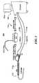
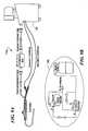
- FIGS. 1 and 1Aillustrate a cryocatheter treatment system and cryocatheter
- FIG. 2is a schematic representation of a coolant system in accordance with one embodiment of the present invention for use with the catheter of FIG. 1;
- FIG. 3is a detailed schematic of another implementation of the coolant system of the present invention.
- FIG. 4Ais a schematic illustration of still another coolant system configuration
- FIG. 4Bis an enthalpy graph with respect to the system of FIG. 4A;
- FIG. 5Ais a schematic illustration of yet another coolant system configuration
- FIG. 5Bis an enthalpy graph with respect to the system of FIG. 5A;
- FIG. 5Cis another enthalpy graph with respect to the system of FIG. 5A;
- FIG. 6schematically represents a refrigerant subcooler that can be included in the coolant system configurations of the invention
- FIG. 7Aillustrates another configuration for a subcooler
- FIG. 7Bis an enthalpy graph with respect to the system of FIG. 7A;
- FIG. 7Cis a schematic illustration of yet another coolant system configuration
- FIG. 7Dis a schematic illustration of yet another coolant configuration
- FIG. 8Aillustrates still another configuration for a subcooler
- FIG. 8Billustrates still another configuration for a subcooler
- FIG. 9Ais a schematic illustration of still another coolant system configuration
- FIG. 9Bis an exemplary subcooling system located the coolant system of FIG. 9A.
- FIG. 10is a schematic illustration of still another coolant system configuration.
- FIG. 1shows a cryogenic treatment system 100 illustrating the general elements thereof.
- System 100includes a treatment catheter 110 having a handle 110 a , a treatment console 120 and number of connecting lines 115 which include signal lines for any monitoring or mapping functions as well as a coolant injection line 115 a and a coolant return line 115 b .
- the consoleincludes a display screen 120 a which may, for example, show both cardiac electrical signals and various status and control screens related to setting or reporting the cooling functions of the catheter or the ablation regimens being administered therewith.
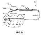
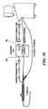
- FIG. 1Ashows in slightly greater detail a catheter 110 used in a system in accordance with the present invention.
- the handle 110 ais equipped with input ports for an electrical connector 111 , a coolant injection tube connector 112 , and a return tube connector 113 . These connect via various internal junctions or tubes passing through the handle to provide these three functions to the distal tip of the catheter.
- the handlemay also include various control assemblies, e.g., switches or valves, as well as safety detection or shut down elements (not illustrated).
- catheter body 110 bLeading from the handle 110 a is an elongated catheter body 110 b which extends to the catheter tip 110 c , illustrated in enlarged detail to show a representative structure thereof.
- the coolantenters through a central tube 1 and exits via a nozzle 2 at the end of the tube to expand in a small contained region forming a chamber 3 at the tip of the catheter.
- the tube 1runs concentrically within an outer tube (not numbered) thereby forming an annular return space 4 surrounding the supply tube 1 and extending back to the fluid return connector 113 of the handle.
- the return passage for expended coolantis a vacuum passage, thus assuring that leakage into the blood stream cannot occur.
- chamber 3defines the cooling region of the catheter tip. In the illustrated embodiment this is a short chamber less than a centimeter long located at the very tip of the catheter. Also shown are a thermocouple 5 positioned within the tip to sense tip temperature, and a plurality of electrodes including a tip electrode 7 a and one or more ring electrodes 8 a , 8 b . . . which are positioned near the tip for use in mapping and/or detecting cardiac signals.
- the chamber 3 defined at the tip of the cathetermay be an elongated chamber several centimeters in length for defining a coolant chamber effective to form linear lesions when placed in contact with tissue such as the cardiac wall.
- the task of the consoleis to provide coolant at the tip region in sufficient quantity and for times effective to create the desired lesions.
- the nature and depth of the lesions createdwill depend on a number of factors, including the temperature attained in the adjacent tissue, as well as the nature of the cooling cycle by which that temperature is attained. In general when the tissue attains an extremely low temperature, or a temperature effective to create ice crystals within tissue cells, the tissue damage will be irreversible, resulting in effective ablation at the contacted site.
- the actual cooling rates achieved at the tipwill depend to a large extent on the area of contact with the tissue as well as the conductive properties of the adjacent tissue and the structure and geometry of the catheter in addition to the nature of coolant flow passing through the catheter tip.
- the latter quantityis controlled, as discussed more fully below, by providing a controller in which the flow of a phase change coolant supplied to the tip is varied to directly control the amount of cooling power available during an ablation cycle.
- the primary cooling effectis achieved by expansion of coolant at the inlet nozzle 2 as it enters chamber 3 .
- thermocouplemay be provided at various places within the catheter to provide useful feedback or emergency control functions. For purposes of the present patent application, such functions will not be further discussed. However, if provided they may be positioned in a discrete cooling system, which for purposes of illustration may be considered to lie entirely within the console 120 , or be external thereto, but in any case to function in relation to the coolant supply elements which will now be described below.
- FIG. 2illustrates one embodiment of a cooling system in accordance with the present invention configured to connect to the inlet and return ports 112 , 113 of the catheter 110 (FIG. 1 A).
- the coolant system 120includes a coolant supply 30 , a coolant conditioner 40 , a coolant control 50 and a coolant return section 60 .
- the control section 50connects to the inlet 112 of the injection catheter, for example by a supply tube, while the return system 60 connects to coolant return port 113 .
- Theseare illustrated as separate connections, but as discussed more fully below, they may be implemented with a single vacuum-jacketed line with a quick connect coupler, or other specialized connection which allows a single coupling to the catheter handle for all coolant functions.
- coolant system 120will be most fully understood from a detailed discussion of each of the subassemblies 30 , 40 , 50 , 60 .
- the coolant systemhas a coolant conditioning section 40 with a compressor that provides a conditioned phase change coolant at elevated pressure to the control section 50 , which, in turn, regulates the supply of coolant provided to the inlet of the catheter.
- the return section 60includes a vacuum pump which continuously draws expended coolant from the catheter at lower pressure and returns it at higher pressure to the coolant conditioner 40 , thereby providing a closed circulation loop through the catheter to meet the required ablation or mapping regimens.
- the conditionerprovides coolant substantially at ambient temperature or colder
- the controllerincludes an electronically controlled pressure regulator which sets the flow rate of the coolant injected into the catheter, thus regulating the cooling action of the catheter tip.
- Conditioned coolantis provided to the control section by the conditioner 40 , which receives coolant at lower pressure either from the return section 60 or from the supply 30 , compresses the coolant to a high pressure, liquefies the coolant, and brings it to approximately ambient temperature at its outlet line 42 a leading to the controller.
- the output from the compressorhas a second branch 42 b in which excess coolant is not further cooled, but is simply returned to the supply 30 .
- conditioner section 40in addition to the raising the pressure of the coolant supplied to the regulator for controlled injection into the catheter, also conditions the temperature of the high pressure coolant. This is preferably done as shown in FIG. 2, by heat exchange between the inlet supply line 41 and the compressor outlet line 42 .
- the compressor outlet line 42is placed in heat exchange communication, for example via a condenser or heat exchanger 45 b , with the inlet line 41 .
- one output branch 42 a of the outlet line 42is placed in heat exchange communication, for example via exchanger 45 a , with an upstream portion of the inlet line 41 .
- the compressor 43operates to compress the coolant from a relatively low pressure, preferably below atmospheric, to a considerably higher pressure, e.g., 20 to 30 atmospheres as measured in its outlet line 42 .
- the material in line 42is therefore heated by compression, and the heat exchange with inlet line 41 serves to reduce the temperature rise generated by compression.
- the catheter injection supply of coolantis effectively brought to or near ambient temperature or colder, while the downstream heat exchange effected in heat exchanger 45 b with the entire output of the compressor is cooled to a lesser extent, serving a more traditional function of liquefying the coolant output and enhancing the overall cooling capacity of the compressed fluid.
- This ordered heat exchange arrangementprovides preferentially greater cooling to the catheter-directed supply line, resulting in a stabilized catheter input over a broader range of operating cycles.
- the high pressure return 42 b to the tankmay be implemented with a pressure regulator located in-line ahead of the tank inlet to assure that coolant is returned to the tank only when its use elsewhere in the circulation loop is not required, and that the pressure in the line first builds up to a level higher than the current tank pressure.
- the system of the present inventionprovides a closed-loop coolant circulation system wherein coolant is conditioned for provision to the inlet of a control module which injects the coolant into a catheter, and the coolant returns in a closed-loop to provide a continuous circulation of fluid at ambient temperature or colder into the catheter.
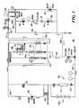
- FIG. 3shows a prototype embodiment in greater detail, illustrating representative valves and regulators for implementing a preferred closed-loop coolant supply 200 .
- the coolant supply, compressor, control and return portions of system 200are numbered with numerals 230 , 240 , 250 , and 260 corresponding to the related subassemblies 30 , 40 , 50 and 60 of system 20 .
- a refrigerant tank 231equipped with a magnetic sight glass 231 a to indicate fill level, supplies refrigerant through a needle valve 232 along line 233 to a downstream pressure regulator 235 .
- the pressure regulator 235converts the nominal tank pressure of several hundred pounds per square inch to a fixed level of 14 psia to provide a constant supply pressure to the inlet line 241 of the compressor. At this stage the refrigerant is boiling at a temperature of about ⁇ 60° Fahrenheit.
- the vacuum recovery return line 262joins the refrigerant inlet 241 at this point.
- the compressor inlet line 241passes through heat exchanger 245 en route to the compressor 243 , and also passes through a condenser 244 , so the low pressure liquid in the inlet line 241 is heated by the hot vapor coming out of the compressor, causing it to become a vapor.
- the compressor 243takes the vapor and pressurizes it to about 400 psi.
- the pressurized outputpasses along line 242 through dryers D and sight glass SG, after which the high pressure outlet line bifurcates into two branches 242 b and 242 a .
- An upstream pressure regulator 246 in line 242 bbuilds and maintains pressure in the high pressure output line allowing the regulator to open and return excess refrigerant to the tank 231 when the pressure reaches a preset level, of about 400 psi, which is higher than the nominal tank pressure, e.g., 200 psi.
- the second branch 242 a of the output line 242passes through the heat exchanger 245 located in the upstream portion of the input line 241 , where it is further cooled to provide a conditioned output to the controller 250 , which as shown includes a motorized pressure regulator 254 .
- Pressure regulator 254controls the flow rate of coolant provided along line 251 to the inlet port of the catheter (illustrated schematically).
- the pressure regulator 254may be controlled by a control microprocessor in the console to provide coolant at a pressure of 250 psi for a time interval of 2.5 minutes. Control is generally done by actuating the motor of regulator 254 to achieve a desired set point and leaving the regulator at that setting for the indicated time period.
- a zero to 500 psi pressure transducer 255is placed in line 251 to provide feedback signals for implementing the control of the regulator 254 , which may further employ feedback from the thermocouple in the catheter.
- the return line 115 b from the catheterattaches to vacuum section 260 , while a solenoid operated purge valve 257 extends between the catheter inlet line 251 and the low pressure return line 262 from the vacuum scavenging system 260 . It will be understood that purge valve 257 will typically be operated to bleed the inlet line when the catheter is first attached and the supply compressor or return pump, respectively, are operated.
- the return line 115 b from the catheterpasses via vacuum protection solenoid-operated valve 261 to a vacuum pump 265 , which maintains a vacuum in the range of 2 to 40 millibars in the return line, and which increases the pressure of the expended coolant vapor to approximately 15 psi.
- a similar solenoid operated protection valve 261 ais provided together with a check ball, and an oil filter OF which prevents pump oil from contaminating the circulating coolant or depositing in the coolant valves, catheter passages or other components.
- a filtere.g., 0.5 ⁇ m, appears in the catheter inlet line 251 .
- the entire vacuum systemmay be isolated by the solenoid operated protection valves 261 , 261 a , during start-up or during a sensed over-pressure or blood leakage condition, and a check valve 265 prevents any pressure build-up on the vacuum pressure side of the catheter in the event of pump or compressor failure, allowing coolant return directly into the return line 262 and compressor inlet 241 .
- the compressor output or various bypass or check valves 257 , 264are set a pressure slightly higher than the output setting of the tank conditioner regulator 235 , so that the coolant normally circulates into the catheter and through the vacuum system back into the compressor as a closed-loop.
- a coolant refill port 275is provided at a solenoid operated valve 277 in the compressor inlet line 241 , allowing a refrigerant bottle attached at that point to employ the same compressor 243 of the system to refill the supply tank 231 .
- a solenoid operated by-pass valve 237is also supplied to bypass the upstream high pressure return regulator 246 between the compressor output line 242 b and the tank, and speed up refill of the tank 231 .
- a solenoid operated valve 238connects to a vent port to allow venting of any air which may have accumulated in the refrigerant tank due to leakage through the catheter or tubing.
- This ventis preferably controlled automatically by a suitable control program in the console 120 . Venting may be implemented, for example, by providing a temperature sensor in the refrigerant tank and a pressure sensor at its top. Knowing the temperature of the liquid refrigerant in the tank, the vent may be operated until the saturated pressure is reached for the given refrigerant at the indicated tank temperature. Such a venting step is to be performed each time the console is turned on.
- various pressure indicators or temperature sensorsmay be situated along the different lines to indicate operating parameters of the fluid therein. These are preferably sensors or indicators of the process control type wherein, rather than a dial display output, they provide an electrical output which connects to a microprocessor programmed to monitor the various conditions continuously to detect relevant safety, control or maintenance conditions.
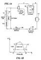
- FIG. 4Aanother embodiment of a closed-loop system is shown schematically, wherein letters A through F correspond to points on a system enthalpy graph depicted at FIG. 4 B.
- letters A through Fcorrespond to points on a system enthalpy graph depicted at FIG. 4 B.
- Of particular interest in the graph of FIG. 4Bare the areas representing a refrigerant in liquid state, gas state, and a mixed state that includes variable percentages of liquid and gas.
- the system of FIG. 4Aincludes a compressor 300 that pressurizes refrigerant in a gas state and passes it through a first cooler or condenser 302 .
- the refrigeranttransitions from a gas state to a transition or combination liquid and gas state, wherein almost all of the refrigerant is liquid, or if liquid, very close to the point where the refrigerant changes state to a gas.
- the refrigerantpasses through a filter or contaminant remover 304 and thence to a secondary cooler, referred to herein as a subcooler 306 .
- the subcooler 306chills the refrigerant to a lower temperature than that achieved by the compressor to cause the refrigerant to be completely in the liquid state prior to transfer to a catheter 310 .
- the subcooler 306chills the refrigerant to a temperature colder than 10° C. to enable the catheter tip to be chilled to temperatures as low as ⁇ 90° C.
- the refrigerant or coolantshould exit the injection tube 1 (see FIG. 1A) as a liquid.
- the coolantis at or near point “C” as shown in FIG. 4 B (at the liquid/gas border).
- point “C”as shown in FIG. 4 B (at the liquid/gas border).
- the subcooler 306is located within the console 120 or one of its accessories 115 c . This helps to minimize weight and cost of a disposable handle and or catheter components, and it allows the catheter to be much smaller in diameter than a catheter having a secondary or subcooler in the handle or in the catheter. Additionally, locating the subcooler 306 in the console and/or its accessories minimizes the space occupied or required by cooling equipment within the catheter, thereby facilitating use of very small diameter catheters (e.g., 3 Fr to 7 Fr) for cryotreatments.
- very small diameter catheterse.g., 3 Fr to 7 Fr
- FIGS. 4A and 4Billustrate the refrigerant as the refrigerant is ejected from the line leading from the subcooler 306 , it is allowed to change phase from a liquid to a gas and to expand in a low pressure or near vacuum environment created by a vacuum pump 312 at the catheter tip 314 .
- FIG. 4Billustrates the sudden transition from liquid to gas as represented by points “D” to “E” to “F” and to “A” on the enthalpy graph.
- the vacuum pump 312causes the expanded gas to be returned to the compressor 300 so the cycle can be repeated.
- FIGS. 5A and 5Billustrate another cooling system configuration that is similar to the closed-loop system shown in FIG. 4 A.
- Refrigerantis supplied to the system from a tank or cartridge 316 in substantially liquid state or very close to the point where the refrigerant changes state from liquid to gas (point “C” on the graph of FIG. 5 B).
- the refrigerantpasses through a filter or contaminant remover 318 and then to a subcooler 320 .
- the subcooler 320chills the refrigerant to a temperature that causes the refrigerant to be completely in the liquid state (point “D” on the graph of FIG. 5B) prior to transfer to a catheter 322 .
- FIG. 5Billustrates the sudden transition from liquid to gas as represented by points “D” to “E” to “F” and to “G” on the enthalpy graph.
- the vacuum pumpcauses the expanded gas to conveyed to a collection tank or other scavenging system 326 . Cryotreatment can continue until the refrigerant supply bottle 316 is no longer capable of providing liquid refrigerant.
- a quick-connect/disconnect mechanism 328is associated with the supply bottle 316 .
- a vacuum pumpis not used and the expanded gas is directly conveyed to the collection tank or other scavenging system 326 .
- the expanded gasis released to the atmosphere surrounding the system, with no scavenging or collecting system used.
- FIGS. 5A and 5Can alternate arrangement of a cooling system configuration is illustrated.
- refrigerantis supplied to the system from the tank or cartridge 316 in a substantially gas state (point “B” on the graph of FIG. 5 C).
- the refrigerantpasses through the filter or contaminant remover 318 (optional) and then to the subcooler 320 .
- the subcooler 320chills the refrigerant to a temperature that causes the refrigerant to transition to the liquid state (point “D” on the graph of FIG. 5C) prior to transfer to the catheter 322 .
- FIG. 5Cillustrates the sudden transition from the second liquid state to the gas state as represented by points “E” to “F” and to “G” on the enthalpy graph.
- the vacuum pumpcauses the expanded gas to be conveyed to a collection tank or other scavenging system 326 . Cryotreatment can continue until the refrigerant supply bottle 316 is no longer capable of providing liquid refrigerant.
- phase states represented by FIG. 5Ccan be employed in any of the structural embodiments constructed in accordance with the present invention.
- Supplying the refrigerant to the chamber 360 in a gas statehas the added advantage of providing consistent control of the flow and temperature characteristics of the refrigerant.
- Refrigerant in the gas phaseis less susceptible to fluctuations that can occur due to the refrigerant's inherently unstable nature at the gas-liquid transition phase.
- a subcooler or subcooling system compatible with these systemscan include a Peltier cooler, a Joule-Thompson, a Stirling engine or an independent closed-loop refrigeration system.
- control of the ratio of gas and liquid in a coolantcan be performed with temperature control, the invention also contemplates use of pressure control in the console and subcooler to control the ratio.
- FIG. 6discloses an exemplary, independent, closed-loop subcooler in schematic form.
- the subcoolerincludes a chamber 330 through which passes a coiled refrigerant transfer line 332 .
- a compressor 334 and condenser 336provide liquid refrigerant that is transferred into the chamber 330 as shown by the arrow marked “Ref. in.”
- the coolantif compressed gas expands, or if liquid changes state to gas, thereby chilling the transfer line 332 and its contents.
- the expanded, gas-state coolantis exhausted from the chamber 330 as shown by the arrow marked “Ref. out” and returned to the compressor 334 .
- a capillary tube 338can be interposed between the condenser 336 and the chamber 330 in order to reduce the flow injected in the heat exchanger 330 .
- an insulated enclosure 340(like chamber 330 ) encloses a coiled portion of a coolant supply line 342 leading to a medical implement (not shown) as described above.
- the coolant supply line 342is in communication with a coolant reservoir 348 (such as bottled, liquid N 2 O) to allow coolant to be directed into the enclosure 340 .
- An outlet 350 in communication with a vacuum source 351is provided to exhaust coolant from the enclosure 340 whereupon it is directed to a scavenging system.
- Cooling performancecan be controlled with a coolant flow regulator 352 that can be made responsive to a temperature sensor 354 within the enclosure 340 that outputs a signal to a temperature controller 355 that controls the flow regulator 352 .
- coolant or refrigerantcan be supplied in a liquid phase or a gas phase
- FIG. 7Bis an enthalpy graph (representing refrigerant supplied in the liquid phase) for the system illustrated in FIG. 7 A.
- the enthalpy graph shown in FIG. 5Crepresents the phases of the coolant along the flow path (representing refrigerant supplied in the gas phase).
- FIG. 7Cis a schematic illustration of an alternate embodiment of a subcooler.
- Chamber 360is depicted having an outlet 364 .
- a conduit 366Provided within the camber 360 is a conduit 366 , having a first end 367 and a second end 369 , defining a fluid flow path for a coolant or a refrigerant.
- the conduit 366defines an inlet 362 .
- a refrigerantis supplied to the first end 367 which then passes through the body of the conduit 366 to the second end 369 .
- the rate of flow through the inlet 362can be controlled by the size of the inlet 362 as well as by flow control valves as discussed herein (not shown).
- the diameter of the inlet 362can range from 0.0001 to ⁇ 0.03 inches. In an exemplary embodiment the diameter of the inlet 362 is 0.002 inches.
- the rate of subcooling affected within the chamber 360can be regulated by adjusting the flow rate of the outlet 364 .
- the location of the inlet 362 along the conduit 366can be varied, for example, the inlet 362 can be provided closer to the second end 369 than is shown in FIG. 7 C. It is also contemplated the that the location of the outlet 364 along the chamber 360 can be varied, for example the outlet 364 can be provided closer to the first end 367 than is shown in FIG. 7 C.
- FIG. 7Dis a schematic view of another alternate embodiment of a subcooler illustrated in more detail.
- FIG. 7Dillustrates another cooling system configuration that is similar to the closed-loop system shown in FIG. 5A with an alternate subcooler location and further incorporating the exemplary subcooler arrangement of FIG. 7 C.
- Refrigerantis supplied to the system from a tank or cartridge 516 in substantially liquid state or substantially gas state as discussed in detail above.
- the refrigerantpasses through a filter or contaminant remover 518 (optional) and then to a junction 519 .
- One branch of the junctionpasses through a vent system 521 and the other branch passes through subcooler 520 .
- the subcooler 520chills the refrigerant to a temperature that causes the refrigerant to be in the liquid state prior to transfer to a catheter 522 .
- the arrangement shown in FIG. 7Dhas the added advantage of permitting placement of the subcooler within accessories external to the console, for example, in an connection box as shown in FIG. 10 below, in a catheter handle assembly or any other such device located between the catheter and the console.
- FIG. 7DThe function of the system shown in FIG. 7D follows that described above. It is contemplated that the subcooler embodiment shown in FIG. 7C can be used in any of the alternate systems discussed herein. It is further contemplated that the physical arrangement of the individual components can follow the layout shown in FIG. 7D as well as other arrangements disclosed herein.
- FIG. 8Ayet another configuration for a subcooler is illustrated in conjunction with a control system for the subcooler.
- this illustrationdepicts a chamber 360 , having an inlet 362 and an outlet 364 , provides a flow path for refrigerant such as nitrous oxide or another fluid.
- a conduit 366 that defines a second fluid flow path for the same refrigerantpasses through the chamber 360 and is in fluid communication with a refrigerant supply upstream of the chamber and a medical device downstream from the chamber.
- a fluid flow splitter 368can allow a common refrigerant source to be used for supplying the chamber 360 and the conduit 366 .
- a programmable controller 370is in communication with and controls one or more valves, such as a first valve 372 , to regulate flow of coolant through the conduit 366 and into the medical device in response to a programmed cooling profile and in response to sensor outputs from the catheter. Additionally, the controller 370 can be used to control a second valve 374 to regulate flow of coolant through the chamber 360 in response to sensed temperature within the chamber. For example, the controller 370 can establish a duty cycle that opens and closes the second valve 374 repeatedly over time. If the temperature rises in the chamber 360 the second valve 374 can be opened and closed more frequently. By contrast, if the temperature in the chamber falls too far, the second valve 374 can be cycled less frequently.
- Another exampleincludes establishing a duty cycle to specifically regulate the temperature increases and decreases at the treatment site. It has been found advantageous to be able to precisely control the freezing and thawing rates when performing a procedure as described above. Further, by sensing the actual temperatures and adjusting the opening and closing of the system valves, the application of specific temperature regimens can be accomplished.
- thermoelectric cooler 400such as a peltier cooler, the operation of which is known in the art.
- the thermoelectric coolerhas a hot side 420 and a cold side 440 .
- a conduit 466is provided adjacent and in thermally-conductive communication with the cold side 440 of the thermoelectric cooler 400 .
- a supplemental cooler 460is provided adjacent to and in thermally-conductive communication with the hot side 420 of the thermoelectric cooler 400 .
- the conduit 466 , the thermoelectric cooler 400 and the supplemental cooler 460are enclosed by a housing 480 .
- the supplemental cooler 460is connected to an external cooling source 500 which can be any of the cooling arrangements disclosed herein or other such devices, for example, a compressor system as shown in FIG. 6 can be used.
- thermoelectric coolerWhen the thermoelectric cooler is activated, the temperature of the cold side 440 is reduced and thereby reduces the temperature of the adjacent conduit 466 , which in turn reduces the temperature of refrigerant passing through the conduit 466 . Further, the hot side 420 increases in temperature.
- the cooling source 500supplies cold energy to the supplemental cooler 460 which thereby cools the adjacent hot side 420 . By cooling the hot side 420 , heat is removed from the housing 480 and the cooling efficiency of the supplemental cooler 460 is increased. As described above, it is desirable to provide a reduced temperature to the conduit 466 to thereby liquify any refrigerant or coolant that is passed through the conduit 466 .
- the hot side 420can be cooled by more conventional means such as moving air across the hot side 420 .
- a heat sinkcan be provided in thermal communication with the hot side 420 to increase cooling efficiency. Operations of such devices will be readily apparent to one skilled in the art based upon the disclosure of the present invention.
- subcooling systemscan be located within the console 120 or its accessories 115 c instead of in the catheter or in the catheter handle (the part held by the surgeon to manipulate the catheter).
- “console”is intended to mean any component that is not a part of the operative implement.
- the “console”can be considered to be everything but the catheter and the handle. Illustrations of this feature are shown in FIGS. 9, 9 A and 10 , wherein FIG. 9A illustrates exemplary subcooling system components 380 being located entirely within the console 120 .
- FIG. 10illustrates a system wherein a subcooler 382 is positioned within an ECG connection box 384 .
- the subcooler 382can be configured for cooling as described above, it can include any other known cooling device that can be located within an accessory such as an ECO connection box.
Landscapes
- Health & Medical Sciences (AREA)
- Surgery (AREA)
- Life Sciences & Earth Sciences (AREA)
- Nuclear Medicine, Radiotherapy & Molecular Imaging (AREA)
- Medical Informatics (AREA)
- General Health & Medical Sciences (AREA)
- Biomedical Technology (AREA)
- Heart & Thoracic Surgery (AREA)
- Otolaryngology (AREA)
- Molecular Biology (AREA)
- Animal Behavior & Ethology (AREA)
- Engineering & Computer Science (AREA)
- Public Health (AREA)
- Veterinary Medicine (AREA)
- Thermotherapy And Cooling Therapy Devices (AREA)
- Surgical Instruments (AREA)
- Heating, Cooling, Or Curing Plastics Or The Like In General (AREA)
- Magnetic Resonance Imaging Apparatus (AREA)
- Measuring And Recording Apparatus For Diagnosis (AREA)
Abstract
Description
Claims (18)
Priority Applications (12)
| Application Number | Priority Date | Filing Date | Title |
|---|---|---|---|
| US09/771,031US6592577B2 (en) | 1999-01-25 | 2001-01-26 | Cooling system |
| AT02710716TATE320766T1 (en) | 2001-01-26 | 2002-01-25 | PRE-COOLED MEDICAL LOW TEMPERATURE DEVICE |
| DE60210046TDE60210046T2 (en) | 2001-01-26 | 2002-01-25 | PRE-COOLED MEDICAL TEMPERATURE DEVICE |
| CA2651835ACA2651835C (en) | 2001-01-26 | 2002-01-25 | Precooled cryogenic medical system |
| PCT/CA2002/000088WO2002058576A1 (en) | 2001-01-26 | 2002-01-25 | Precooled cryogenic medical system |
| CA002435429ACA2435429C (en) | 2001-01-26 | 2002-01-25 | Catheter |
| EP02710716AEP1357847B1 (en) | 2001-01-26 | 2002-01-25 | Pre-cooled cryogenic medical system |
| CA2651832ACA2651832C (en) | 2001-01-26 | 2002-01-25 | Precooled cryogenic medical system |
| US10/619,366US7207986B2 (en) | 1999-01-25 | 2003-07-14 | Cooling system |
| US11/581,185US8361059B2 (en) | 1999-01-25 | 2006-10-13 | Cooling system |
| US11/709,964US7780657B2 (en) | 1999-01-25 | 2007-02-23 | Cooling system |
| US11/710,205US20070233055A1 (en) | 1999-01-25 | 2007-02-23 | Cooling system |
Applications Claiming Priority (4)
| Application Number | Priority Date | Filing Date | Title |
|---|---|---|---|
| US11717599P | 1999-01-25 | 1999-01-25 | |
| US09/489,646US6383180B1 (en) | 1999-01-25 | 2000-01-24 | Closed loop catheter coolant system |
| US09/638,208US6635053B1 (en) | 1999-01-25 | 2000-08-11 | Cooling system |
| US09/771,031US6592577B2 (en) | 1999-01-25 | 2001-01-26 | Cooling system |
Related Parent Applications (1)
| Application Number | Title | Priority Date | Filing Date |
|---|---|---|---|
| US09/638,208Continuation-In-PartUS6635053B1 (en) | 1999-01-25 | 2000-08-11 | Cooling system |
Related Child Applications (1)
| Application Number | Title | Priority Date | Filing Date |
|---|---|---|---|
| US10/619,366ContinuationUS7207986B2 (en) | 1999-01-25 | 2003-07-14 | Cooling system |
Publications (2)
| Publication Number | Publication Date |
|---|---|
| US20010021847A1 US20010021847A1 (en) | 2001-09-13 |
| US6592577B2true US6592577B2 (en) | 2003-07-15 |
Family
ID=25090471
Family Applications (5)
| Application Number | Title | Priority Date | Filing Date |
|---|---|---|---|
| US09/771,031Expired - LifetimeUS6592577B2 (en) | 1999-01-25 | 2001-01-26 | Cooling system |
| US10/619,366Expired - Fee RelatedUS7207986B2 (en) | 1999-01-25 | 2003-07-14 | Cooling system |
| US11/581,185Expired - Fee RelatedUS8361059B2 (en) | 1999-01-25 | 2006-10-13 | Cooling system |
| US11/709,964Expired - LifetimeUS7780657B2 (en) | 1999-01-25 | 2007-02-23 | Cooling system |
| US11/710,205AbandonedUS20070233055A1 (en) | 1999-01-25 | 2007-02-23 | Cooling system |
Family Applications After (4)
| Application Number | Title | Priority Date | Filing Date |
|---|---|---|---|
| US10/619,366Expired - Fee RelatedUS7207986B2 (en) | 1999-01-25 | 2003-07-14 | Cooling system |
| US11/581,185Expired - Fee RelatedUS8361059B2 (en) | 1999-01-25 | 2006-10-13 | Cooling system |
| US11/709,964Expired - LifetimeUS7780657B2 (en) | 1999-01-25 | 2007-02-23 | Cooling system |
| US11/710,205AbandonedUS20070233055A1 (en) | 1999-01-25 | 2007-02-23 | Cooling system |
Country Status (6)
| Country | Link |
|---|---|
| US (5) | US6592577B2 (en) |
| EP (1) | EP1357847B1 (en) |
| AT (1) | ATE320766T1 (en) |
| CA (3) | CA2651832C (en) |
| DE (1) | DE60210046T2 (en) |
| WO (1) | WO2002058576A1 (en) |
Cited By (79)
| Publication number | Priority date | Publication date | Assignee | Title |
|---|---|---|---|---|
| US20030220634A1 (en)* | 2000-08-09 | 2003-11-27 | Ryba Eric L. | Refrigeration source for a cryoablation catheter |
| US20040024413A1 (en)* | 2002-07-31 | 2004-02-05 | Lentz David J. | Wire reinforced articulation segment |
| US20040034345A1 (en)* | 2002-08-16 | 2004-02-19 | Lentz David J. | Heat transfer segment for a cryoablation catheter |
| US20040034365A1 (en)* | 2002-08-16 | 2004-02-19 | Lentz David J. | Catheter having articulation system |
| US20040034344A1 (en)* | 2002-08-16 | 2004-02-19 | Eric Ryba | Tip pressure monitoring for cryoablation catheters |
| US20040116921A1 (en)* | 2002-12-11 | 2004-06-17 | Marshall Sherman | Cold tip rf/ultrasonic ablation catheter |
| US20040116917A1 (en)* | 2002-12-11 | 2004-06-17 | Lentz David J. | System and method for performing a single step cryoablation |
| US20040116916A1 (en)* | 2002-12-11 | 2004-06-17 | Lentz David J. | Coaxial catheter system for performing a single step cryoablation |
| US6824543B2 (en) | 2002-12-11 | 2004-11-30 | Cryocor, Inc. | Guidance system for a cryocatheter |
| US20040243118A1 (en)* | 2001-06-01 | 2004-12-02 | Ayers Gregory M. | Device and method for positioning a catheter tip for creating a cryogenic lesion |
| US20050016188A1 (en)* | 2003-07-24 | 2005-01-27 | Lentz David J. | Distal end for cryoablation catheters |
| US20050027289A1 (en)* | 2003-07-31 | 2005-02-03 | Thomas Castellano | Cryoablation systems and methods |
| US20050177146A1 (en)* | 2004-02-10 | 2005-08-11 | Marshall Sherman | System and method for assessing ice ball formation during a cryoablation procedure |
| US20050198972A1 (en)* | 2004-03-10 | 2005-09-15 | Lentz David J. | Pressure-temperature control for a cryoablation catheter system |
| US20050283146A1 (en)* | 2004-06-17 | 2005-12-22 | Lentz David J | Thermally extended spiral cryotip for a cryoablation catheter |
| US20050288657A1 (en)* | 2004-06-29 | 2005-12-29 | Lentz David J | Pressure monitor for cryoablation catheter |
| US20060004349A1 (en)* | 2004-06-30 | 2006-01-05 | Eric Ryba | System for detecting leaks and occlusions in a cryoablation catheter |
| US20060175543A1 (en)* | 2005-02-08 | 2006-08-10 | John Elefteriades | Intra-thecal catheter and method for cooling the spinal cord |
| US20070010861A1 (en)* | 2002-03-15 | 2007-01-11 | Anderson Richard R | Methods and devices for selective disruption of fatty tissue by controlled cooling |
| WO2007027171A1 (en)* | 2005-08-29 | 2007-03-08 | Carrier Corporation | Thermoelectric device based refrigerant subcooling |
| US7195625B2 (en) | 2002-12-11 | 2007-03-27 | Cryocor, Inc. | Catheter system for performing a single step cryoablation |
| USRE40049E1 (en)* | 1999-06-25 | 2008-02-12 | Ams Research Corporation | Precooled cryogenic ablation system |
| US7357797B2 (en) | 2004-06-30 | 2008-04-15 | Cryocor, Inc. | System and method for varying return pressure to control tip temperature of a cryoablation catheter |
| US20080262418A1 (en)* | 2007-04-05 | 2008-10-23 | Daniel Rogers Burnett | Automated Therapy System and Method |
| US20090171333A1 (en)* | 2007-12-27 | 2009-07-02 | Boston Scientific Scimed, Inc. | System and method for controllably delivering liquid coolant to a cryo-ablation device |
| US20090287201A1 (en)* | 2008-05-16 | 2009-11-19 | Jean-Pierre Lalonde | Thermocouple-controlled catether cooling system |
| US20090299356A1 (en)* | 2008-05-29 | 2009-12-03 | Boston Scientific Scimed, Inc. | Regulating internal pressure of a cryotherapy balloon catheter |
| US7777130B2 (en) | 2007-06-18 | 2010-08-17 | Vivant Medical, Inc. | Microwave cable cooling |
| US20100241114A1 (en)* | 2009-03-20 | 2010-09-23 | Salvatore Privitera | Cryogenic probe |
| US7854754B2 (en) | 2006-02-22 | 2010-12-21 | Zeltiq Aesthetics, Inc. | Cooling device for removing heat from subcutaneous lipid-rich cells |
| US20110054453A1 (en)* | 2009-09-02 | 2011-03-03 | Jean-Pierre Lalonde | Cryotreatment device using a supercritical gas |
| US8192474B2 (en) | 2006-09-26 | 2012-06-05 | Zeltiq Aesthetics, Inc. | Tissue treatment methods |
| US8275442B2 (en) | 2008-09-25 | 2012-09-25 | Zeltiq Aesthetics, Inc. | Treatment planning systems and methods for body contouring applications |
| US8285390B2 (en) | 2007-08-21 | 2012-10-09 | Zeltiq Aesthetics, Inc. | Monitoring the cooling of subcutaneous lipid-rich cells, such as the cooling of adipose tissue |
| US20130008182A1 (en)* | 2009-12-16 | 2013-01-10 | Brian Hrudka | Self-contained temperature controlled apparatus |
| US8439960B2 (en) | 2007-07-09 | 2013-05-14 | Velomedix, Inc. | Hypothermia devices and methods |
| US8491636B2 (en)* | 2004-03-23 | 2013-07-23 | Medtronic Cryopath LP | Method and apparatus for inflating and deflating balloon catheters |
| US8523854B2 (en) | 2008-08-28 | 2013-09-03 | Covidien Lp | Microwave antenna |
| US8523927B2 (en) | 2007-07-13 | 2013-09-03 | Zeltiq Aesthetics, Inc. | System for treating lipid-rich regions |
| US8603073B2 (en) | 2008-12-17 | 2013-12-10 | Zeltiq Aesthetics, Inc. | Systems and methods with interrupt/resume capabilities for treating subcutaneous lipid-rich cells |
| US8676338B2 (en) | 2010-07-20 | 2014-03-18 | Zeltiq Aesthetics, Inc. | Combined modality treatment systems, methods and apparatus for body contouring applications |
| US8702774B2 (en) | 2009-04-30 | 2014-04-22 | Zeltiq Aesthetics, Inc. | Device, system and method of removing heat from subcutaneous lipid-rich cells |
| US8840608B2 (en) | 2002-03-15 | 2014-09-23 | The General Hospital Corporation | Methods and devices for selective disruption of fatty tissue by controlled cooling |
| US9132031B2 (en) | 2006-09-26 | 2015-09-15 | Zeltiq Aesthetics, Inc. | Cooling device having a plurality of controllable cooling elements to provide a predetermined cooling profile |
| US9314368B2 (en) | 2010-01-25 | 2016-04-19 | Zeltiq Aesthetics, Inc. | Home-use applicators for non-invasively removing heat from subcutaneous lipid-rich cells via phase change coolants, and associates devices, systems and methods |
| US9545523B2 (en) | 2013-03-14 | 2017-01-17 | Zeltiq Aesthetics, Inc. | Multi-modality treatment systems, methods and apparatus for altering subcutaneous lipid-rich tissue |
| USD777338S1 (en) | 2014-03-20 | 2017-01-24 | Zeltiq Aesthetics, Inc. | Cryotherapy applicator for cooling tissue |
| US9622670B2 (en) | 2010-07-09 | 2017-04-18 | Potrero Medical, Inc. | Method and apparatus for pressure measurement |
| US9844460B2 (en) | 2013-03-14 | 2017-12-19 | Zeltiq Aesthetics, Inc. | Treatment systems with fluid mixing systems and fluid-cooled applicators and methods of using the same |
| US9861421B2 (en) | 2014-01-31 | 2018-01-09 | Zeltiq Aesthetics, Inc. | Compositions, treatment systems and methods for improved cooling of lipid-rich tissue |
| US10045817B2 (en) | 2010-11-16 | 2018-08-14 | Tva Medical, Inc. | Devices and methods for forming a fistula |
| US10335230B2 (en) | 2011-03-09 | 2019-07-02 | Covidien Lp | Systems for thermal-feedback-controlled rate of fluid flow to fluid-cooled antenna assembly and methods of directing energy to tissue using same |
| US10383787B2 (en) | 2007-05-18 | 2019-08-20 | Zeltiq Aesthetics, Inc. | Treatment apparatus for removing heat from subcutaneous lipid-rich cells and massaging tissue |
| US10524956B2 (en) | 2016-01-07 | 2020-01-07 | Zeltiq Aesthetics, Inc. | Temperature-dependent adhesion between applicator and skin during cooling of tissue |
| US10555831B2 (en) | 2016-05-10 | 2020-02-11 | Zeltiq Aesthetics, Inc. | Hydrogel substances and methods of cryotherapy |
| US10568759B2 (en) | 2014-08-19 | 2020-02-25 | Zeltiq Aesthetics, Inc. | Treatment systems, small volume applicators, and methods for treating submental tissue |
| US10603040B1 (en) | 2015-02-09 | 2020-03-31 | Tva Medical, Inc. | Methods for treating hypertension and reducing blood pressure with formation of fistula |
| US10646666B2 (en) | 2014-08-27 | 2020-05-12 | Tva Medical, Inc. | Cryolipolysis devices and methods therefor |
| US10675176B1 (en) | 2014-03-19 | 2020-06-09 | Zeltiq Aesthetics, Inc. | Treatment systems, devices, and methods for cooling targeted tissue |
| US10682297B2 (en) | 2016-05-10 | 2020-06-16 | Zeltiq Aesthetics, Inc. | Liposomes, emulsions, and methods for cryotherapy |
| US10695534B2 (en) | 2014-03-14 | 2020-06-30 | Tva Medical, Inc. | Fistula formation devices and methods therefor |
| US10722395B2 (en) | 2011-01-25 | 2020-07-28 | Zeltiq Aesthetics, Inc. | Devices, application systems and methods with localized heat flux zones for removing heat from subcutaneous lipid-rich cells |
| US10765552B2 (en) | 2016-02-18 | 2020-09-08 | Zeltiq Aesthetics, Inc. | Cooling cup applicators with contoured heads and liner assemblies |
| US10821217B2 (en) | 2013-03-14 | 2020-11-03 | Tva Medical, Inc. | Fistula formation devices and methods therefor |
| US10869717B2 (en) | 2012-10-11 | 2020-12-22 | Tva Medical, Inc. | Devices and methods for fistula formation |
| US10874422B2 (en) | 2016-01-15 | 2020-12-29 | Tva Medical, Inc. | Systems and methods for increasing blood flow |
| US10935174B2 (en) | 2014-08-19 | 2021-03-02 | Zeltiq Aesthetics, Inc. | Stress relief couplings for cryotherapy apparatuses |
| US10952891B1 (en) | 2014-05-13 | 2021-03-23 | Zeltiq Aesthetics, Inc. | Treatment systems with adjustable gap applicators and methods for cooling tissue |
| US11026743B2 (en) | 2016-01-15 | 2021-06-08 | Tva Medical, Inc. | Devices and methods for forming a fistula |
| US11076879B2 (en) | 2017-04-26 | 2021-08-03 | Zeltiq Aesthetics, Inc. | Shallow surface cryotherapy applicators and related technology |
| US11154418B2 (en) | 2015-10-19 | 2021-10-26 | Zeltiq Aesthetics, Inc. | Vascular treatment systems, cooling devices, and methods for cooling vascular structures |
| US11285028B2 (en) | 2016-09-25 | 2022-03-29 | Tva Medical, Inc. | Vascular stent devices and methods |
| US11382790B2 (en) | 2016-05-10 | 2022-07-12 | Zeltiq Aesthetics, Inc. | Skin freezing systems for treating acne and skin conditions |
| US11446175B2 (en) | 2018-07-31 | 2022-09-20 | Zeltiq Aesthetics, Inc. | Methods, devices, and systems for improving skin characteristics |
| US11590322B2 (en) | 2016-01-15 | 2023-02-28 | Tva Medical, Inc. | Devices and methods for advancing a wire |
| US11771486B2 (en) | 2017-01-17 | 2023-10-03 | Corfigo, Inc. | Device for ablation of tissue surfaces and related systems and methods |
| US11986421B2 (en) | 2006-09-26 | 2024-05-21 | Zeltiq Aesthetics, Inc. | Cooling devices with flexible sensors |
| US12070411B2 (en) | 2006-04-28 | 2024-08-27 | Zeltiq Aesthetics, Inc. | Cryoprotectant for use with a treatment device for improved cooling of subcutaneous lipid-rich cells |
| US12295645B2 (en) | 2016-01-15 | 2025-05-13 | Tva Medical, Inc. | Systems and methods for adhering vessels |
Families Citing this family (84)
| Publication number | Priority date | Publication date | Assignee | Title |
|---|---|---|---|---|
| US6592577B2 (en)* | 1999-01-25 | 2003-07-15 | Cryocath Technologies Inc. | Cooling system |
| US7363071B2 (en) | 1999-05-26 | 2008-04-22 | Endocare, Inc. | Computer guided ablation of tissue using integrated ablative/temperature sensing devices |
| US6621071B2 (en)* | 2001-09-07 | 2003-09-16 | Raytheon Co. | Microelectronic system with integral cryocooler, and its fabrication and use |
| US7479139B2 (en)* | 2002-01-04 | 2009-01-20 | Galil Medical Ltd. | Apparatus and method for protecting tissues during cryoablation |
| US20040024392A1 (en)* | 2002-08-05 | 2004-02-05 | Lewis James D. | Apparatus and method for cryosurgery |
| US7410484B2 (en) | 2003-01-15 | 2008-08-12 | Cryodynamics, Llc | Cryotherapy probe |
| CA2931693C (en)* | 2003-01-15 | 2017-03-14 | Cryodynamics, Llc | Cryotherapy probe and system |
| KR100466866B1 (en)* | 2003-04-24 | 2005-01-24 | 전명기 | Electrode for radiofrequency tissue ablation |
| US9555223B2 (en)* | 2004-03-23 | 2017-01-31 | Medtronic Cryocath Lp | Method and apparatus for inflating and deflating balloon catheters |
| US7727228B2 (en) | 2004-03-23 | 2010-06-01 | Medtronic Cryocath Lp | Method and apparatus for inflating and deflating balloon catheters |
| US20060047245A1 (en)* | 2004-08-24 | 2006-03-02 | Ruchir Sehra | Catheter control unit |
| US7604631B2 (en) | 2004-12-15 | 2009-10-20 | Boston Scientific Scimed, Inc. | Efficient controlled cryogenic fluid delivery into a balloon catheter and other treatment devices |
| US20060178662A1 (en)* | 2005-02-04 | 2006-08-10 | Ripley Kenneth L | Warming gradient control for a cryoablation applicator |
| US8206345B2 (en) | 2005-03-07 | 2012-06-26 | Medtronic Cryocath Lp | Fluid control system for a medical device |
| GB0521585D0 (en)* | 2005-10-22 | 2005-11-30 | Depuy Int Ltd | A spinal support rod |
| GB0521582D0 (en)* | 2005-10-22 | 2005-11-30 | Depuy Int Ltd | An implant for supporting a spinal column |
| GB0600662D0 (en)* | 2006-01-13 | 2006-02-22 | Depuy Int Ltd | Spinal support rod kit |
| US8348952B2 (en)* | 2006-01-26 | 2013-01-08 | Depuy International Ltd. | System and method for cooling a spinal correction device comprising a shape memory material for corrective spinal surgery |
| US20070270925A1 (en)* | 2006-05-17 | 2007-11-22 | Juniper Medical, Inc. | Method and apparatus for non-invasively removing heat from subcutaneous lipid-rich cells including a coolant having a phase transition temperature |
| WO2008055243A2 (en)* | 2006-10-31 | 2008-05-08 | Zeltiq Aesthetics, Inc. | Method and apparatus for cooling subcutaneous lipid-rich cells or tissue |
| US20090018626A1 (en)* | 2007-07-13 | 2009-01-15 | Juniper Medical, Inc. | User interfaces for a system that removes heat from lipid-rich regions |
| US20090018625A1 (en)* | 2007-07-13 | 2009-01-15 | Juniper Medical, Inc. | Managing system temperature to remove heat from lipid-rich regions |
| US20090018627A1 (en)* | 2007-07-13 | 2009-01-15 | Juniper Medical, Inc. | Secure systems for removing heat from lipid-rich regions |
| US20090018624A1 (en)* | 2007-07-13 | 2009-01-15 | Juniper Medical, Inc. | Limiting use of disposable system patient protection devices |
| GB0720762D0 (en) | 2007-10-24 | 2007-12-05 | Depuy Spine Sorl | Assembly for orthopaedic surgery |
| JP5254988B2 (en)* | 2007-11-02 | 2013-08-07 | 国立大学法人名古屋大学 | Cryotherapy equipment |
| EP2057952B1 (en)* | 2007-11-09 | 2014-01-29 | AFreeze GmbH | Cooling system for a catheter |
| JP2011521679A (en) | 2008-05-12 | 2011-07-28 | ボストン サイエンティフィック サイムド,インコーポレイテッド | Equipment for cooling the cryoablation coolant |
| EP2291132B1 (en) | 2008-05-15 | 2015-09-23 | Boston Scientific Scimed, Inc. | Apparatus for cryogenically ablating tissue and adjusting cryogenic ablation regions |
| DE102008045563B9 (en)* | 2008-07-02 | 2012-01-26 | Erbe Elektromedizin Gmbh | Temperature control for a cryoprobe, cryosurgical device with temperature controller and method for controlling the temperature of a cryoprobe |
| US8945106B2 (en)* | 2008-07-03 | 2015-02-03 | Steve Arless | Tip design for cryogenic probe with inner coil injection tube |
| JP5233031B2 (en)* | 2008-07-15 | 2013-07-10 | 株式会社デージーエス・コンピュータ | Cryotherapy planning device and cryotherapy device |
| US9408654B2 (en)* | 2008-09-03 | 2016-08-09 | Endocare, Inc. | Modular pulsed pressure device for the transport of liquid cryogen to a cryoprobe |
| US9089316B2 (en) | 2009-11-02 | 2015-07-28 | Endocare, Inc. | Cryogenic medical system |
| US8784409B2 (en)* | 2008-09-03 | 2014-07-22 | Endocare, Inc. | Cryogenic system and method of use |
| US10182859B2 (en) | 2008-09-03 | 2019-01-22 | Endocare, Inc. | Medical device for the transport of subcooled cryogenic fluid through a linear heat exchanger |
| US10695126B2 (en) | 2008-10-06 | 2020-06-30 | Santa Anna Tech Llc | Catheter with a double balloon structure to generate and apply a heated ablative zone to tissue |
| WO2010083281A1 (en)* | 2009-01-15 | 2010-07-22 | Boston Scientific Scimed, Inc. | Controlling depth of cryoablation |
| US20100241113A1 (en)* | 2009-03-20 | 2010-09-23 | Boston Scientific Scimed, Inc. | Protecting the phrenic nerve while ablating cardiac tissue |
| US8672938B2 (en)* | 2009-07-23 | 2014-03-18 | Covidien Lp | Active cooling system and apparatus for controlling temperature of a fluid used during treatment of biological tissue |
| WO2011151354A2 (en)* | 2010-06-01 | 2011-12-08 | Afreeze Gmbh | Leakage protection system, pressure balancing system, and precipitator with valve function for ablation applications |
| US20120089047A1 (en) | 2010-08-05 | 2012-04-12 | Medtronic Vascular, Inc. | Cryoablation apparatuses, systems, and methods for renal neuromodulation |
| US20120158104A1 (en) | 2010-10-26 | 2012-06-21 | Medtronic Ardian Luxembourg S.A.R.L. | Neuromodulation cryotherapeutic devices and associated systems and methods |
| US9060754B2 (en) | 2010-10-26 | 2015-06-23 | Medtronic Ardian Luxembourg S.A.R.L. | Neuromodulation cryotherapeutic devices and associated systems and methods |
| US12201340B2 (en) | 2011-03-25 | 2025-01-21 | Medtronic Cryocath Lp | Spray nozzle design for a catheter |
| US9439707B2 (en) | 2011-03-25 | 2016-09-13 | Medtronic Cryocath Lp | Spray nozzle design for a catheter |
| WO2012148969A2 (en) | 2011-04-25 | 2012-11-01 | Brian Kelly | Apparatus and methods related to constrained deployment of cryogenic balloons for limited cryogenic ablation of vessel walls |
| US20120283722A1 (en)* | 2011-05-02 | 2012-11-08 | Medtronic Ablation Frontiers Llc | Adiabatic cooling system for medical devices |
| JP5804414B2 (en)* | 2011-08-11 | 2015-11-04 | 国立大学法人東北大学 | Cryosurgical apparatus and temperature control method thereof |
| US20150148791A1 (en)* | 2011-11-05 | 2015-05-28 | Medtronic Ardian Luxemborug S.a.r.l. | Systems, devices and methods for cryogenic renal neuromodulation |
| US9144449B2 (en)* | 2012-03-02 | 2015-09-29 | Csa Medical, Inc. | Cryosurgery system |
| US9301796B2 (en)* | 2012-03-02 | 2016-04-05 | Csa Medical, Inc. | Cryosurgery system |
| US9241752B2 (en) | 2012-04-27 | 2016-01-26 | Medtronic Ardian Luxembourg S.A.R.L. | Shafts with pressure relief in cryotherapeutic catheters and associated devices, systems, and methods |
| CN104411263A (en) | 2012-04-27 | 2015-03-11 | 美敦力阿迪安卢森堡有限公司 | Cryotherapeutic devices for renal neuromodulation and associated systems and methods |
| US9095321B2 (en) | 2012-11-21 | 2015-08-04 | Medtronic Ardian Luxembourg S.A.R.L. | Cryotherapeutic devices having integral multi-helical balloons and methods of making the same |
| US9017317B2 (en) | 2012-12-06 | 2015-04-28 | Medtronic Ardian Luxembourg S.A.R.L. | Refrigerant supply system for cryotherapy including refrigerant recompression and associated devices, systems, and methods |
| US9522030B2 (en)* | 2013-01-23 | 2016-12-20 | Medtronic Cryocath Lp | Purge phase for cryoablation systems |
| CA2904190C (en)* | 2013-03-04 | 2022-08-16 | Csa Medical, Inc. | Cryospray catheters |
| CN109846543B (en) | 2013-09-24 | 2021-09-21 | 艾达吉欧医疗公司 | Cryoablation catheter based on intravascular near-critical fluid and related methods |
| US10492842B2 (en) | 2014-03-07 | 2019-12-03 | Medtronic Ardian Luxembourg S.A.R.L. | Monitoring and controlling internally administered cryotherapy |
| US10054262B2 (en)* | 2014-04-16 | 2018-08-21 | Cpsi Holdings Llc | Pressurized sub-cooled cryogenic system |
| EP3131487A4 (en) | 2014-04-17 | 2017-12-13 | Adagio Medical, Inc. | Endovascular near critical fluid based cryoablation catheter having plurality of preformed treatment shapes |
| CA2951050A1 (en) | 2014-06-04 | 2015-12-10 | Csa Medical, Inc. | Method and system for consistent, repeatable, and safe cryospray treatment of airway tissue |
| US9956024B2 (en) | 2014-07-11 | 2018-05-01 | Medtronic Cryocath Lp | Cryoablation method and system |
| CA2965314C (en) | 2014-11-13 | 2021-07-06 | Adagio Medical, Inc. | Pressure modulated cryoablation system and related methods |
| US9993280B2 (en) | 2015-07-02 | 2018-06-12 | Medtronic Cryocath Lp | N2O thermal pressurization system by cooling |
| US10433894B2 (en)* | 2015-07-02 | 2019-10-08 | Medtronic Cryocath Lp | N2O liquefaction system with subcooling heat exchanger for medical device |
| EP3349676A4 (en) | 2015-09-18 | 2019-05-15 | Adagio Medical, Inc. | TISSUE CONTACT VERIFICATION SYSTEM |
| US10864031B2 (en) | 2015-11-30 | 2020-12-15 | Adagio Medical, Inc. | Ablation method for creating elongate continuous lesions enclosing multiple vessel entries |
| JP6820121B2 (en) | 2016-04-27 | 2021-01-27 | シーエスエー メディカル, インコーポレイテッド | Vision-securing device for medical devices |
| US12364537B2 (en) | 2016-05-02 | 2025-07-22 | Santa Anna Tech Llc | Catheter with a double balloon structure to generate and apply a heated ablative zone to tissue |
| US11331140B2 (en) | 2016-05-19 | 2022-05-17 | Aqua Heart, Inc. | Heated vapor ablation systems and methods for treating cardiac conditions |
| US11871977B2 (en) | 2016-05-19 | 2024-01-16 | Csa Medical, Inc. | Catheter extension control |
| KR102736370B1 (en) | 2017-09-05 | 2024-11-29 | 아다지오 메디컬, 인크. | Ablation catheter with shape memory stylet |
| US11648047B2 (en) | 2017-10-06 | 2023-05-16 | Vive Scientific, Llc | System and method to treat obstructive sleep apnea |
| CN107951558B (en)* | 2017-11-10 | 2021-05-14 | 上海导向医疗系统有限公司 | Multifunctional gas pipeline controlled cryoablation system |
| BR112020013967A2 (en) | 2018-01-10 | 2020-12-01 | Adagio Medical, Inc. | cryoablation element with conductive lining |
| US11633224B2 (en) | 2020-02-10 | 2023-04-25 | Icecure Medical Ltd. | Cryogen pump |
| CN112370147B (en)* | 2021-01-15 | 2021-04-09 | 上海安钛克医疗科技有限公司 | Control handle of balloon catheter, balloon catheter and cryoablation system |
| EP4039209A1 (en) | 2021-02-04 | 2022-08-10 | AFreeze GmbH | Cryoablation catheter assembly, cryoablation system |
| US12426934B2 (en) | 2022-02-28 | 2025-09-30 | Icecure Medical Ltd. | Cryogen flow control |
| CN115077112B (en)* | 2022-07-14 | 2025-02-18 | 江苏大学 | A refrigerant spray-assisted skin cooling, refrigerant recovery and treatment system and working method thereof |
| US12215811B2 (en) | 2022-07-18 | 2025-02-04 | Icecure Medical Ltd. | Cryogenic system connector |
| GB2630757A (en)* | 2023-06-06 | 2024-12-11 | CryoTherapeutics SA | Refrigerant electromechanical control |
Citations (37)
| Publication number | Priority date | Publication date | Assignee | Title |
|---|---|---|---|---|
| US3823575A (en) | 1971-06-07 | 1974-07-16 | Univ Melbourne | Cryogenic apparatus |
| US3859986A (en) | 1973-06-20 | 1975-01-14 | Jiro Okada | Surgical device |
| GB2026324A (en) | 1978-06-23 | 1980-02-06 | Bracco D | Cryotherapy apparatus |
| US5275595A (en) | 1992-07-06 | 1994-01-04 | Dobak Iii John D | Cryosurgical instrument |
| EP0651308A1 (en) | 1993-11-01 | 1995-05-03 | State of Israel Ministry of Defence Raphael Armament Development Authority | Controlled cryogenic contact system |
| WO1996030816A1 (en) | 1995-03-31 | 1996-10-03 | Spembly Cryosurgery Limited | Method and apparatus for supplying liquid cryogen |
| US5651780A (en) | 1991-11-08 | 1997-07-29 | Ep Technologies, Inc. | Systems for identifying catheters and monitoring their use |
| US5658278A (en) | 1992-12-01 | 1997-08-19 | Cardiac Pathways, Inc. | Catheter for RF ablation with cooled electrode and method |
| US5674218A (en) | 1990-09-26 | 1997-10-07 | Cryomedical Sciences, Inc. | Cryosurgical instrument and system and method of cryosurgery |
| US5743903A (en) | 1991-11-08 | 1998-04-28 | Ep Technologies, Inc. | Cardiac ablation systems and methods using tissue temperature monitoring and control |
| US5758505A (en)* | 1995-10-12 | 1998-06-02 | Cryogen, Inc. | Precooling system for joule-thomson probe |
| WO1998037822A1 (en) | 1997-02-27 | 1998-09-03 | Cryocath Technologies Inc. | Method and apparatus for linear ablation |
| US5807391A (en) | 1993-10-26 | 1998-09-15 | Cordis Corporation | Cryo-ablation catheter |
| US5957963A (en) | 1998-01-23 | 1999-09-28 | Del Mar Medical Technologies, Inc. | Selective organ hypothermia method and apparatus |
| WO1999057494A1 (en) | 1998-05-07 | 1999-11-11 | Cryogen, Inc. | Precooling system for joule-thomson probe |
| WO1999056640A1 (en) | 1998-04-30 | 1999-11-11 | Spembly Medical Limited | Improvements relating to cryosurgical apparatus |
| WO1999056641A1 (en) | 1998-04-30 | 1999-11-11 | Spembly Medical Limited | Cryosurgical apparatus |
| WO1999056639A1 (en) | 1998-04-30 | 1999-11-11 | Spembly Medical Limited | Arrangement for cooled probes |
| US6007571A (en) | 1996-04-25 | 1999-12-28 | Urologix, Inc. | Liquid coolant supply system |
| US6016661A (en) | 1997-10-18 | 2000-01-25 | Sagar; Christopher L. | Refrigerant recovery system |
| US6019783A (en) | 1999-03-02 | 2000-02-01 | Alsius Corporation | Cooling system for therapeutic catheter |
| US6027500A (en) | 1998-05-05 | 2000-02-22 | Buckles; David S. | Cardiac ablation system |
| US6027499A (en) | 1997-05-23 | 2000-02-22 | Fiber-Tech Medical, Inc. (Assignee Of Jennifer B. Cartledge) | Method and apparatus for cryogenic spray ablation of gastrointestinal mucosa |
| US6032675A (en) | 1997-03-17 | 2000-03-07 | Rubinsky; Boris | Freezing method for controlled removal of fatty tissue by liposuction |
| US6033383A (en) | 1996-12-19 | 2000-03-07 | Ginsburg; Robert | Temperature regulating catheter and methods |
| US6039730A (en) | 1996-06-24 | 2000-03-21 | Allegheny-Singer Research Institute | Method and apparatus for cryosurgery |
| WO2000035362A2 (en) | 1998-12-14 | 2000-06-22 | Spembly Medical Limited | Cryogen supply apparatus |
| US6096068A (en) | 1998-01-23 | 2000-08-01 | Innercool Therapies, Inc. | Selective organ cooling catheter and method of using the same |
| US6106518A (en) | 1998-04-09 | 2000-08-22 | Cryocath Technologies, Inc. | Variable geometry tip for a cryosurgical ablation device |
| US6146411A (en) | 1998-12-24 | 2000-11-14 | Alsius Corporation | Cooling system for indwelling heat exchange catheter |
| US6149677A (en) | 1998-03-31 | 2000-11-21 | Innercool Therapies, Inc. | Circulating fluid hypothermia method |
| US6161543A (en) | 1993-02-22 | 2000-12-19 | Epicor, Inc. | Methods of epicardial ablation for creating a lesion around the pulmonary veins |
| WO2001001049A1 (en) | 1999-06-25 | 2001-01-04 | Cryogen, Inc. | Precooled cryogenic ablation system |
| US6190378B1 (en) | 1997-12-05 | 2001-02-20 | Massachusetts Institute Of Technology | Cryosurgical instrument and related techniques |
| US6193644B1 (en) | 1996-12-26 | 2001-02-27 | Cryogen, Inc. | Cryosurgical probe with sheath |
| US6241722B1 (en)* | 1998-06-17 | 2001-06-05 | Cryogen, Inc. | Cryogenic device, system and method of using same |
| US6306129B1 (en)* | 1997-09-22 | 2001-10-23 | Femrx, Inc. | Cryosurgical system and method |
Family Cites Families (9)
| Publication number | Priority date | Publication date | Assignee | Title |
|---|---|---|---|---|
| US3782386A (en)* | 1972-05-08 | 1974-01-01 | Dynatech Corp | Cryosurgical apparatus |
| DE3238535A1 (en)* | 1982-10-18 | 1984-04-19 | Planer Products Ltd., Sunbury-on-Thames, Middlesex | Process and apparatus for controlled cooling of a product |
| US4696168A (en)* | 1986-10-01 | 1987-09-29 | Roger Rasbach | Refrigerant subcooler for air conditioning systems |
| US5097829A (en)* | 1990-03-19 | 1992-03-24 | Tony Quisenberry | Temperature controlled cooling system |
| WO1997022486A1 (en)* | 1995-12-15 | 1997-06-26 | Climcon A/S | A heat exchanger device for an air conditioning system |
| US5830208A (en)* | 1997-01-31 | 1998-11-03 | Laserlite, Llc | Peltier cooled apparatus and methods for dermatological treatment |
| US6592577B2 (en) | 1999-01-25 | 2003-07-15 | Cryocath Technologies Inc. | Cooling system |
| US6468268B1 (en) | 1999-01-25 | 2002-10-22 | Cryocath Technologies Inc. | Cryogenic catheter system |
| US6471694B1 (en)* | 2000-08-09 | 2002-10-29 | Cryogen, Inc. | Control system for cryosurgery |
- 2001
- 2001-01-26USUS09/771,031patent/US6592577B2/ennot_activeExpired - Lifetime
- 2002
- 2002-01-25CACA2651832Apatent/CA2651832C/ennot_activeExpired - Fee Related
- 2002-01-25DEDE60210046Tpatent/DE60210046T2/ennot_activeExpired - Lifetime
- 2002-01-25EPEP02710716Apatent/EP1357847B1/ennot_activeExpired - Lifetime
- 2002-01-25CACA002435429Apatent/CA2435429C/ennot_activeExpired - Fee Related
- 2002-01-25ATAT02710716Tpatent/ATE320766T1/ennot_activeIP Right Cessation
- 2002-01-25WOPCT/CA2002/000088patent/WO2002058576A1/ennot_activeApplication Discontinuation
- 2002-01-25CACA2651835Apatent/CA2651835C/ennot_activeExpired - Fee Related
- 2003
- 2003-07-14USUS10/619,366patent/US7207986B2/ennot_activeExpired - Fee Related
- 2006
- 2006-10-13USUS11/581,185patent/US8361059B2/ennot_activeExpired - Fee Related
- 2007
- 2007-02-23USUS11/709,964patent/US7780657B2/ennot_activeExpired - Lifetime
- 2007-02-23USUS11/710,205patent/US20070233055A1/ennot_activeAbandoned
Patent Citations (40)
| Publication number | Priority date | Publication date | Assignee | Title |
|---|---|---|---|---|
| US3823575A (en) | 1971-06-07 | 1974-07-16 | Univ Melbourne | Cryogenic apparatus |
| US3859986A (en) | 1973-06-20 | 1975-01-14 | Jiro Okada | Surgical device |
| GB2026324A (en) | 1978-06-23 | 1980-02-06 | Bracco D | Cryotherapy apparatus |
| US5674218A (en) | 1990-09-26 | 1997-10-07 | Cryomedical Sciences, Inc. | Cryosurgical instrument and system and method of cryosurgery |
| US5743903A (en) | 1991-11-08 | 1998-04-28 | Ep Technologies, Inc. | Cardiac ablation systems and methods using tissue temperature monitoring and control |
| US5651780A (en) | 1991-11-08 | 1997-07-29 | Ep Technologies, Inc. | Systems for identifying catheters and monitoring their use |
| US5275595A (en) | 1992-07-06 | 1994-01-04 | Dobak Iii John D | Cryosurgical instrument |
| US5658278A (en) | 1992-12-01 | 1997-08-19 | Cardiac Pathways, Inc. | Catheter for RF ablation with cooled electrode and method |
| US6161543A (en) | 1993-02-22 | 2000-12-19 | Epicor, Inc. | Methods of epicardial ablation for creating a lesion around the pulmonary veins |
| US5807391A (en) | 1993-10-26 | 1998-09-15 | Cordis Corporation | Cryo-ablation catheter |
| EP0651308A1 (en) | 1993-11-01 | 1995-05-03 | State of Israel Ministry of Defence Raphael Armament Development Authority | Controlled cryogenic contact system |
| WO1996030816A1 (en) | 1995-03-31 | 1996-10-03 | Spembly Cryosurgery Limited | Method and apparatus for supplying liquid cryogen |
| US5758505A (en)* | 1995-10-12 | 1998-06-02 | Cryogen, Inc. | Precooling system for joule-thomson probe |
| US5758505C1 (en)* | 1995-10-12 | 2001-10-30 | Cryogen Inc | Precooling system for joule-thomson probe |
| US6007571A (en) | 1996-04-25 | 1999-12-28 | Urologix, Inc. | Liquid coolant supply system |
| US6039730A (en) | 1996-06-24 | 2000-03-21 | Allegheny-Singer Research Institute | Method and apparatus for cryosurgery |
| US6033383A (en) | 1996-12-19 | 2000-03-07 | Ginsburg; Robert | Temperature regulating catheter and methods |
| US6193644B1 (en) | 1996-12-26 | 2001-02-27 | Cryogen, Inc. | Cryosurgical probe with sheath |
| WO1998037822A1 (en) | 1997-02-27 | 1998-09-03 | Cryocath Technologies Inc. | Method and apparatus for linear ablation |
| US6032675A (en) | 1997-03-17 | 2000-03-07 | Rubinsky; Boris | Freezing method for controlled removal of fatty tissue by liposuction |
| US6027499A (en) | 1997-05-23 | 2000-02-22 | Fiber-Tech Medical, Inc. (Assignee Of Jennifer B. Cartledge) | Method and apparatus for cryogenic spray ablation of gastrointestinal mucosa |
| US6306129B1 (en)* | 1997-09-22 | 2001-10-23 | Femrx, Inc. | Cryosurgical system and method |
| US6016661A (en) | 1997-10-18 | 2000-01-25 | Sagar; Christopher L. | Refrigerant recovery system |
| US6190378B1 (en) | 1997-12-05 | 2001-02-20 | Massachusetts Institute Of Technology | Cryosurgical instrument and related techniques |
| US6096068A (en) | 1998-01-23 | 2000-08-01 | Innercool Therapies, Inc. | Selective organ cooling catheter and method of using the same |
| US5957963A (en) | 1998-01-23 | 1999-09-28 | Del Mar Medical Technologies, Inc. | Selective organ hypothermia method and apparatus |
| US6235048B1 (en)* | 1998-01-23 | 2001-05-22 | Innercool Therapies, Inc. | Selective organ hypothermia method and apparatus |
| US6051019A (en) | 1998-01-23 | 2000-04-18 | Del Mar Medical Technologies, Inc. | Selective organ hypothermia method and apparatus |
| US6149677A (en) | 1998-03-31 | 2000-11-21 | Innercool Therapies, Inc. | Circulating fluid hypothermia method |
| US6106518A (en) | 1998-04-09 | 2000-08-22 | Cryocath Technologies, Inc. | Variable geometry tip for a cryosurgical ablation device |
| WO1999056640A1 (en) | 1998-04-30 | 1999-11-11 | Spembly Medical Limited | Improvements relating to cryosurgical apparatus |
| WO1999056639A1 (en) | 1998-04-30 | 1999-11-11 | Spembly Medical Limited | Arrangement for cooled probes |
| WO1999056641A1 (en) | 1998-04-30 | 1999-11-11 | Spembly Medical Limited | Cryosurgical apparatus |
| US6027500A (en) | 1998-05-05 | 2000-02-22 | Buckles; David S. | Cardiac ablation system |
| WO1999057494A1 (en) | 1998-05-07 | 1999-11-11 | Cryogen, Inc. | Precooling system for joule-thomson probe |
| US6241722B1 (en)* | 1998-06-17 | 2001-06-05 | Cryogen, Inc. | Cryogenic device, system and method of using same |
| WO2000035362A2 (en) | 1998-12-14 | 2000-06-22 | Spembly Medical Limited | Cryogen supply apparatus |
| US6146411A (en) | 1998-12-24 | 2000-11-14 | Alsius Corporation | Cooling system for indwelling heat exchange catheter |
| US6019783A (en) | 1999-03-02 | 2000-02-01 | Alsius Corporation | Cooling system for therapeutic catheter |
| WO2001001049A1 (en) | 1999-06-25 | 2001-01-04 | Cryogen, Inc. | Precooled cryogenic ablation system |
Cited By (155)
| Publication number | Priority date | Publication date | Assignee | Title |
|---|---|---|---|---|
| USRE40049E1 (en)* | 1999-06-25 | 2008-02-12 | Ams Research Corporation | Precooled cryogenic ablation system |
| USRE40868E1 (en) | 1999-06-25 | 2009-08-11 | Cryocor, Inc. | Refrigeration source for a cryoblation catheter |
| US7004936B2 (en) | 2000-08-09 | 2006-02-28 | Cryocor, Inc. | Refrigeration source for a cryoablation catheter |
| US20030220634A1 (en)* | 2000-08-09 | 2003-11-27 | Ryba Eric L. | Refrigeration source for a cryoablation catheter |
| US20040243118A1 (en)* | 2001-06-01 | 2004-12-02 | Ayers Gregory M. | Device and method for positioning a catheter tip for creating a cryogenic lesion |
| US9358149B2 (en) | 2002-03-15 | 2016-06-07 | The General Hospital Corporation | Systems for affecting subcutaneous lipid-rich cells, systems for removing heat from subcutaneous lipid-rich cells, and systems for reducing subcutaneous lipid-rich cells |
| US9308120B2 (en) | 2002-03-15 | 2016-04-12 | The General Hospital Corporation | Methods and devices for selective disruption of fatty tissue by controlled cooling |
| US8840608B2 (en) | 2002-03-15 | 2014-09-23 | The General Hospital Corporation | Methods and devices for selective disruption of fatty tissue by controlled cooling |
| US20070010861A1 (en)* | 2002-03-15 | 2007-01-11 | Anderson Richard R | Methods and devices for selective disruption of fatty tissue by controlled cooling |
| US8834547B2 (en) | 2002-03-15 | 2014-09-16 | The General Hospital Corporation | Treatment systems for removing heat from subcutaneous lipid-rich cells |
| US7367341B2 (en) | 2002-03-15 | 2008-05-06 | The General Hospital Corporation | Methods and devices for selective disruption of fatty tissue by controlled cooling |
| US9649220B2 (en) | 2002-03-15 | 2017-05-16 | The General Hospital Corporation | Treatment systems for removing heat from subcutaneous lipid-rich cells |
| US11590020B2 (en) | 2002-03-15 | 2023-02-28 | The General Hospital Corporation | Methods and devices for selective disruption of fatty tissue by controlled cooling |
| US7004937B2 (en) | 2002-07-31 | 2006-02-28 | Cryocor, Inc. | Wire reinforced articulation segment |
| US20040024413A1 (en)* | 2002-07-31 | 2004-02-05 | Lentz David J. | Wire reinforced articulation segment |
| US6955673B2 (en) | 2002-08-16 | 2005-10-18 | Cryocor, Inc. | Heat transfer segment for a cryoablation catheter |
| US20040034345A1 (en)* | 2002-08-16 | 2004-02-19 | Lentz David J. | Heat transfer segment for a cryoablation catheter |
| US20040034365A1 (en)* | 2002-08-16 | 2004-02-19 | Lentz David J. | Catheter having articulation system |
| US20040034344A1 (en)* | 2002-08-16 | 2004-02-19 | Eric Ryba | Tip pressure monitoring for cryoablation catheters |
| US6796979B2 (en) | 2002-12-11 | 2004-09-28 | Cryocor, Inc. | Coaxial catheter system for performing a single step cryoablation |
| US20040116921A1 (en)* | 2002-12-11 | 2004-06-17 | Marshall Sherman | Cold tip rf/ultrasonic ablation catheter |
| US6893433B2 (en) | 2002-12-11 | 2005-05-17 | Cryocor, Inc. | System and method for performing a single step cryoablation |
| US7195625B2 (en) | 2002-12-11 | 2007-03-27 | Cryocor, Inc. | Catheter system for performing a single step cryoablation |
| US20040116917A1 (en)* | 2002-12-11 | 2004-06-17 | Lentz David J. | System and method for performing a single step cryoablation |
| US20040116916A1 (en)* | 2002-12-11 | 2004-06-17 | Lentz David J. | Coaxial catheter system for performing a single step cryoablation |
| US6824543B2 (en) | 2002-12-11 | 2004-11-30 | Cryocor, Inc. | Guidance system for a cryocatheter |
| US20050016188A1 (en)* | 2003-07-24 | 2005-01-27 | Lentz David J. | Distal end for cryoablation catheters |
| US6981382B2 (en) | 2003-07-24 | 2006-01-03 | Cryocor, Inc. | Distal end for cryoablation catheters |
| US20050027289A1 (en)* | 2003-07-31 | 2005-02-03 | Thomas Castellano | Cryoablation systems and methods |
| US7070594B2 (en) | 2004-02-10 | 2006-07-04 | Cryocor, Inc. | System and method for assessing ice ball formation during a cryoablation procedure |
| US20050177146A1 (en)* | 2004-02-10 | 2005-08-11 | Marshall Sherman | System and method for assessing ice ball formation during a cryoablation procedure |
| US20050198972A1 (en)* | 2004-03-10 | 2005-09-15 | Lentz David J. | Pressure-temperature control for a cryoablation catheter system |
| US8491636B2 (en)* | 2004-03-23 | 2013-07-23 | Medtronic Cryopath LP | Method and apparatus for inflating and deflating balloon catheters |
| US20050283146A1 (en)* | 2004-06-17 | 2005-12-22 | Lentz David J | Thermally extended spiral cryotip for a cryoablation catheter |
| US7156840B2 (en) | 2004-06-29 | 2007-01-02 | Cryocor, Inc. | Pressure monitor for cryoablation catheter |
| US20050288657A1 (en)* | 2004-06-29 | 2005-12-29 | Lentz David J | Pressure monitor for cryoablation catheter |
| US20060004349A1 (en)* | 2004-06-30 | 2006-01-05 | Eric Ryba | System for detecting leaks and occlusions in a cryoablation catheter |
| US7163535B2 (en) | 2004-06-30 | 2007-01-16 | Cryocor, Inc. | System for detecting leaks and occlusions in a cryoablation catheter |
| US7357797B2 (en) | 2004-06-30 | 2008-04-15 | Cryocor, Inc. | System and method for varying return pressure to control tip temperature of a cryoablation catheter |
| US20060175543A1 (en)* | 2005-02-08 | 2006-08-10 | John Elefteriades | Intra-thecal catheter and method for cooling the spinal cord |
| US20090266084A1 (en)* | 2005-08-29 | 2009-10-29 | Rakesh Radhakrishnan | Thermoelectric device based refrigerant subcooling |
| WO2007027171A1 (en)* | 2005-08-29 | 2007-03-08 | Carrier Corporation | Thermoelectric device based refrigerant subcooling |
| CN101297167B (en)* | 2005-08-29 | 2011-09-14 | 开利公司 | Subcooler, vapor compression system and supercooling method |
| US8337539B2 (en) | 2006-02-22 | 2012-12-25 | Zeltiq Aesthetics, Inc. | Cooling device for removing heat from subcutaneous lipid-rich cells |
| US7854754B2 (en) | 2006-02-22 | 2010-12-21 | Zeltiq Aesthetics, Inc. | Cooling device for removing heat from subcutaneous lipid-rich cells |
| US12070411B2 (en) | 2006-04-28 | 2024-08-27 | Zeltiq Aesthetics, Inc. | Cryoprotectant for use with a treatment device for improved cooling of subcutaneous lipid-rich cells |
| US9375345B2 (en) | 2006-09-26 | 2016-06-28 | Zeltiq Aesthetics, Inc. | Cooling device having a plurality of controllable cooling elements to provide a predetermined cooling profile |
| US9132031B2 (en) | 2006-09-26 | 2015-09-15 | Zeltiq Aesthetics, Inc. | Cooling device having a plurality of controllable cooling elements to provide a predetermined cooling profile |
| US8192474B2 (en) | 2006-09-26 | 2012-06-05 | Zeltiq Aesthetics, Inc. | Tissue treatment methods |
| US10292859B2 (en) | 2006-09-26 | 2019-05-21 | Zeltiq Aesthetics, Inc. | Cooling device having a plurality of controllable cooling elements to provide a predetermined cooling profile |
| US11395760B2 (en) | 2006-09-26 | 2022-07-26 | Zeltiq Aesthetics, Inc. | Tissue treatment methods |
| US11219549B2 (en) | 2006-09-26 | 2022-01-11 | Zeltiq Aesthetics, Inc. | Cooling device having a plurality of controllable cooling elements to provide a predetermined cooling profile |
| US11179269B2 (en) | 2006-09-26 | 2021-11-23 | Zeltiq Aesthetics, Inc. | Cooling device having a plurality of controllable cooling elements to provide a predetermined cooling profile |
| US11986421B2 (en) | 2006-09-26 | 2024-05-21 | Zeltiq Aesthetics, Inc. | Cooling devices with flexible sensors |
| US20080262418A1 (en)* | 2007-04-05 | 2008-10-23 | Daniel Rogers Burnett | Automated Therapy System and Method |
| US8100880B2 (en) | 2007-04-05 | 2012-01-24 | Velomedix, Inc. | Automated therapy system and method |
| US8480648B2 (en) | 2007-04-05 | 2013-07-09 | Velomedix, Inc. | Automated therapy system and method |
| US11800992B2 (en) | 2007-04-05 | 2023-10-31 | Theranova, Llc | Device and method for safe access and automated therapy |
| US11291606B2 (en) | 2007-05-18 | 2022-04-05 | Zeltiq Aesthetics, Inc. | Treatment apparatus for removing heat from subcutaneous lipid-rich cells and massaging tissue |
| US10383787B2 (en) | 2007-05-18 | 2019-08-20 | Zeltiq Aesthetics, Inc. | Treatment apparatus for removing heat from subcutaneous lipid-rich cells and massaging tissue |
| US7777130B2 (en) | 2007-06-18 | 2010-08-17 | Vivant Medical, Inc. | Microwave cable cooling |
| US20100243287A1 (en)* | 2007-06-18 | 2010-09-30 | Vivant Medical, Inc. | Microwave Cable Cooling |
| US8093500B2 (en) | 2007-06-18 | 2012-01-10 | Vivant Medical, Inc. | Microwave cable cooling |
| US8439960B2 (en) | 2007-07-09 | 2013-05-14 | Velomedix, Inc. | Hypothermia devices and methods |
| US9655770B2 (en) | 2007-07-13 | 2017-05-23 | Zeltiq Aesthetics, Inc. | System for treating lipid-rich regions |
| US8523927B2 (en) | 2007-07-13 | 2013-09-03 | Zeltiq Aesthetics, Inc. | System for treating lipid-rich regions |
| US9408745B2 (en) | 2007-08-21 | 2016-08-09 | Zeltiq Aesthetics, Inc. | Monitoring the cooling of subcutaneous lipid-rich cells, such as the cooling of adipose tissue |
| US11583438B1 (en) | 2007-08-21 | 2023-02-21 | Zeltiq Aesthetics, Inc. | Monitoring the cooling of subcutaneous lipid-rich cells, such as the cooling of adipose tissue |
| US10675178B2 (en) | 2007-08-21 | 2020-06-09 | Zeltiq Aesthetics, Inc. | Monitoring the cooling of subcutaneous lipid-rich cells, such as the cooling of adipose tissue |
| US8285390B2 (en) | 2007-08-21 | 2012-10-09 | Zeltiq Aesthetics, Inc. | Monitoring the cooling of subcutaneous lipid-rich cells, such as the cooling of adipose tissue |
| US20090171333A1 (en)* | 2007-12-27 | 2009-07-02 | Boston Scientific Scimed, Inc. | System and method for controllably delivering liquid coolant to a cryo-ablation device |
| US20090287201A1 (en)* | 2008-05-16 | 2009-11-19 | Jean-Pierre Lalonde | Thermocouple-controlled catether cooling system |
| US9936998B2 (en) | 2008-05-16 | 2018-04-10 | Medtronic Cryocath Lp | Thermocouple-controlled catheter cooling system |
| US9050069B2 (en)* | 2008-05-16 | 2015-06-09 | Medtronic Cryocath Lp | Thermocouple-controlled catheter cooling system |
| US12042204B2 (en) | 2008-05-16 | 2024-07-23 | Medtronic Cryocath Lp | Thermocouple-controlled catheter cooling system |
| US11026739B2 (en) | 2008-05-16 | 2021-06-08 | Medronic CryoCath LP | Thermocouple-controlled catheter cooling system |
| US8187261B2 (en)* | 2008-05-29 | 2012-05-29 | Boston Scientific Scimed, Inc. | Regulating internal pressure of a cryotherapy balloon catheter |
| US20090299356A1 (en)* | 2008-05-29 | 2009-12-03 | Boston Scientific Scimed, Inc. | Regulating internal pressure of a cryotherapy balloon catheter |
| US8439906B2 (en)* | 2008-05-29 | 2013-05-14 | Boston Scientific Schimed, Inc. | Regulating internal pressure of a cryotherapy balloon catheter |
| US8715274B2 (en) | 2008-05-29 | 2014-05-06 | Boston Scientific Scimed, Inc. | Regulating internal pressure of a cryotherapy balloon catheter |
| US8523854B2 (en) | 2008-08-28 | 2013-09-03 | Covidien Lp | Microwave antenna |
| US10022186B2 (en) | 2008-08-28 | 2018-07-17 | Covidien Lp | Microwave antenna with cooled handle |
| US8795268B2 (en) | 2008-08-28 | 2014-08-05 | Covidien Lp | Microwave antenna |
| US9707038B2 (en) | 2008-08-28 | 2017-07-18 | Covidien Lp | Microwave antenna with cooled handle |
| US9113932B1 (en) | 2008-08-28 | 2015-08-25 | Covidien Lp | Microwave antenna with choke |
| US9375280B2 (en) | 2008-08-28 | 2016-06-28 | Covidien Lp | Microwave antenna with cooling system |
| US11147620B2 (en) | 2008-08-28 | 2021-10-19 | Covidien Lp | Microwave antenna with cooled hub |
| US9198725B2 (en) | 2008-08-28 | 2015-12-01 | Covidien Lp | Microwave antenna with choke |
| US8275442B2 (en) | 2008-09-25 | 2012-09-25 | Zeltiq Aesthetics, Inc. | Treatment planning systems and methods for body contouring applications |
| US8603073B2 (en) | 2008-12-17 | 2013-12-10 | Zeltiq Aesthetics, Inc. | Systems and methods with interrupt/resume capabilities for treating subcutaneous lipid-rich cells |
| US9737434B2 (en) | 2008-12-17 | 2017-08-22 | Zeltiq Aestehtics, Inc. | Systems and methods with interrupt/resume capabilities for treating subcutaneous lipid-rich cells |
| US20100241114A1 (en)* | 2009-03-20 | 2010-09-23 | Salvatore Privitera | Cryogenic probe |
| US8915908B2 (en) | 2009-03-20 | 2014-12-23 | Atricure, Inc. | Cryogenic probe |
| US8702774B2 (en) | 2009-04-30 | 2014-04-22 | Zeltiq Aesthetics, Inc. | Device, system and method of removing heat from subcutaneous lipid-rich cells |
| US11224536B2 (en) | 2009-04-30 | 2022-01-18 | Zeltiq Aesthetics, Inc. | Device, system and method of removing heat from subcutaneous lipid-rich cells |
| US9861520B2 (en) | 2009-04-30 | 2018-01-09 | Zeltiq Aesthetics, Inc. | Device, system and method of removing heat from subcutaneous lipid-rich cells |
| US11452634B2 (en) | 2009-04-30 | 2022-09-27 | Zeltiq Aesthetics, Inc. | Device, system and method of removing heat from subcutaneous lipid-rich cells |
| US8298219B2 (en)* | 2009-09-02 | 2012-10-30 | Medtronic Cryocath Lp | Cryotreatment device using a supercritical gas |
| CN102596119B (en)* | 2009-09-02 | 2014-10-22 | 美敦力 | Cryotherapy device using supercritical gas |
| US20110054453A1 (en)* | 2009-09-02 | 2011-03-03 | Jean-Pierre Lalonde | Cryotreatment device using a supercritical gas |
| CN102596119A (en)* | 2009-09-02 | 2012-07-18 | 美敦力 | Cryotreatment device using a supercritical gas |
| US20130008182A1 (en)* | 2009-12-16 | 2013-01-10 | Brian Hrudka | Self-contained temperature controlled apparatus |
| US9314368B2 (en) | 2010-01-25 | 2016-04-19 | Zeltiq Aesthetics, Inc. | Home-use applicators for non-invasively removing heat from subcutaneous lipid-rich cells via phase change coolants, and associates devices, systems and methods |
| US9844461B2 (en) | 2010-01-25 | 2017-12-19 | Zeltiq Aesthetics, Inc. | Home-use applicators for non-invasively removing heat from subcutaneous lipid-rich cells via phase change coolants |
| US10758135B2 (en) | 2010-07-09 | 2020-09-01 | Potrero Medical, Inc. | Method and apparatus for pressure measurement |
| US9931044B2 (en) | 2010-07-09 | 2018-04-03 | Potrero Medical, Inc. | Method and apparatus for pressure measurement |
| US9622670B2 (en) | 2010-07-09 | 2017-04-18 | Potrero Medical, Inc. | Method and apparatus for pressure measurement |
| US8676338B2 (en) | 2010-07-20 | 2014-03-18 | Zeltiq Aesthetics, Inc. | Combined modality treatment systems, methods and apparatus for body contouring applications |
| US10092346B2 (en) | 2010-07-20 | 2018-10-09 | Zeltiq Aesthetics, Inc. | Combined modality treatment systems, methods and apparatus for body contouring applications |
| US11986236B2 (en) | 2010-11-16 | 2024-05-21 | Tva Medical, Inc. | Devices and methods for forming a fistula |
| US11051880B2 (en) | 2010-11-16 | 2021-07-06 | Tva Medical, Inc. | Devices and methods for forming a fistula |
| US10045817B2 (en) | 2010-11-16 | 2018-08-14 | Tva Medical, Inc. | Devices and methods for forming a fistula |
| US12178501B2 (en) | 2010-11-16 | 2024-12-31 | Tva Medical, Inc. | Devices and methods for forming a fistula |
| US10722395B2 (en) | 2011-01-25 | 2020-07-28 | Zeltiq Aesthetics, Inc. | Devices, application systems and methods with localized heat flux zones for removing heat from subcutaneous lipid-rich cells |
| US10335230B2 (en) | 2011-03-09 | 2019-07-02 | Covidien Lp | Systems for thermal-feedback-controlled rate of fluid flow to fluid-cooled antenna assembly and methods of directing energy to tissue using same |
| US11147622B2 (en) | 2011-03-09 | 2021-10-19 | Covidien Lp | Systems for thermal-feedback-controlled rate of fluid flow to fluid-cooled antenna assembly and methods of directing energy to tissue using same |
| US10869717B2 (en) | 2012-10-11 | 2020-12-22 | Tva Medical, Inc. | Devices and methods for fistula formation |
| US9844460B2 (en) | 2013-03-14 | 2017-12-19 | Zeltiq Aesthetics, Inc. | Treatment systems with fluid mixing systems and fluid-cooled applicators and methods of using the same |
| US11707562B2 (en) | 2013-03-14 | 2023-07-25 | Tva Medical, Inc. | Fistula formation devices and methods therefor |
| US10821217B2 (en) | 2013-03-14 | 2020-11-03 | Tva Medical, Inc. | Fistula formation devices and methods therefor |
| US9545523B2 (en) | 2013-03-14 | 2017-01-17 | Zeltiq Aesthetics, Inc. | Multi-modality treatment systems, methods and apparatus for altering subcutaneous lipid-rich tissue |
| US10806500B2 (en) | 2014-01-31 | 2020-10-20 | Zeltiq Aesthetics, Inc. | Treatment systems, methods, and apparatuses for improving the appearance of skin and providing other treatments |
| US9861421B2 (en) | 2014-01-31 | 2018-01-09 | Zeltiq Aesthetics, Inc. | Compositions, treatment systems and methods for improved cooling of lipid-rich tissue |
| US10201380B2 (en) | 2014-01-31 | 2019-02-12 | Zeltiq Aesthetics, Inc. | Treatment systems, methods, and apparatuses for improving the appearance of skin and providing other treatments |
| US11819257B2 (en) | 2014-01-31 | 2023-11-21 | Zeltiq Aesthetics, Inc. | Compositions, treatment systems and methods for improved cooling of lipid-rich tissue |
| US10912599B2 (en) | 2014-01-31 | 2021-02-09 | Zeltiq Aesthetics, Inc. | Compositions, treatment systems and methods for improved cooling of lipid-rich tissue |
| US10575890B2 (en) | 2014-01-31 | 2020-03-03 | Zeltiq Aesthetics, Inc. | Treatment systems and methods for affecting glands and other targeted structures |
| US11219745B2 (en) | 2014-03-14 | 2022-01-11 | Tva Medical, Inc. | Fistula formation devices and methods therefor |
| US10695534B2 (en) | 2014-03-14 | 2020-06-30 | Tva Medical, Inc. | Fistula formation devices and methods therefor |
| US10675176B1 (en) | 2014-03-19 | 2020-06-09 | Zeltiq Aesthetics, Inc. | Treatment systems, devices, and methods for cooling targeted tissue |
| USD777338S1 (en) | 2014-03-20 | 2017-01-24 | Zeltiq Aesthetics, Inc. | Cryotherapy applicator for cooling tissue |
| US10952891B1 (en) | 2014-05-13 | 2021-03-23 | Zeltiq Aesthetics, Inc. | Treatment systems with adjustable gap applicators and methods for cooling tissue |
| US10935174B2 (en) | 2014-08-19 | 2021-03-02 | Zeltiq Aesthetics, Inc. | Stress relief couplings for cryotherapy apparatuses |
| US10568759B2 (en) | 2014-08-19 | 2020-02-25 | Zeltiq Aesthetics, Inc. | Treatment systems, small volume applicators, and methods for treating submental tissue |
| US10646666B2 (en) | 2014-08-27 | 2020-05-12 | Tva Medical, Inc. | Cryolipolysis devices and methods therefor |
| US10603040B1 (en) | 2015-02-09 | 2020-03-31 | Tva Medical, Inc. | Methods for treating hypertension and reducing blood pressure with formation of fistula |
| US12369916B2 (en) | 2015-02-09 | 2025-07-29 | Tva Medical, Inc. | Methods for treating hypertension and reducing blood pressure with formation of fistula |
| US11207070B2 (en) | 2015-02-09 | 2021-12-28 | Tva Medical, Inc. | Methods for treating hypertension and reducing blood pressure with formation of fistula |
| US11154418B2 (en) | 2015-10-19 | 2021-10-26 | Zeltiq Aesthetics, Inc. | Vascular treatment systems, cooling devices, and methods for cooling vascular structures |
| US10524956B2 (en) | 2016-01-07 | 2020-01-07 | Zeltiq Aesthetics, Inc. | Temperature-dependent adhesion between applicator and skin during cooling of tissue |
| US11826093B2 (en) | 2016-01-15 | 2023-11-28 | Tva Medical, Inc. | Devices and methods for forming a fistula |
| US12295645B2 (en) | 2016-01-15 | 2025-05-13 | Tva Medical, Inc. | Systems and methods for adhering vessels |
| US11590322B2 (en) | 2016-01-15 | 2023-02-28 | Tva Medical, Inc. | Devices and methods for advancing a wire |
| US11026743B2 (en) | 2016-01-15 | 2021-06-08 | Tva Medical, Inc. | Devices and methods for forming a fistula |
| US10874422B2 (en) | 2016-01-15 | 2020-12-29 | Tva Medical, Inc. | Systems and methods for increasing blood flow |
| US10765552B2 (en) | 2016-02-18 | 2020-09-08 | Zeltiq Aesthetics, Inc. | Cooling cup applicators with contoured heads and liner assemblies |
| US10555831B2 (en) | 2016-05-10 | 2020-02-11 | Zeltiq Aesthetics, Inc. | Hydrogel substances and methods of cryotherapy |
| US11382790B2 (en) | 2016-05-10 | 2022-07-12 | Zeltiq Aesthetics, Inc. | Skin freezing systems for treating acne and skin conditions |
| US10682297B2 (en) | 2016-05-10 | 2020-06-16 | Zeltiq Aesthetics, Inc. | Liposomes, emulsions, and methods for cryotherapy |
| US11285028B2 (en) | 2016-09-25 | 2022-03-29 | Tva Medical, Inc. | Vascular stent devices and methods |
| US12427044B2 (en) | 2016-09-25 | 2025-09-30 | Tva Medical, Inc. | Vascular stent devices and methods |
| US11771486B2 (en) | 2017-01-17 | 2023-10-03 | Corfigo, Inc. | Device for ablation of tissue surfaces and related systems and methods |
| US11076879B2 (en) | 2017-04-26 | 2021-08-03 | Zeltiq Aesthetics, Inc. | Shallow surface cryotherapy applicators and related technology |
| US12102557B2 (en) | 2018-07-31 | 2024-10-01 | Zeltiq Aesthetics, Inc. | Methods, devices, and systems for improving skin characteristics |
| US11446175B2 (en) | 2018-07-31 | 2022-09-20 | Zeltiq Aesthetics, Inc. | Methods, devices, and systems for improving skin characteristics |
Also Published As
| Publication number | Publication date |
|---|---|
| US20040049178A1 (en) | 2004-03-11 |
| DE60210046D1 (en) | 2006-05-11 |
| US20010021847A1 (en) | 2001-09-13 |
| ATE320766T1 (en) | 2006-04-15 |
| WO2002058576A1 (en) | 2002-08-01 |
| EP1357847A1 (en) | 2003-11-05 |
| US8361059B2 (en) | 2013-01-29 |
| CA2435429C (en) | 2010-01-05 |
| CA2435429A1 (en) | 2002-08-01 |
| CA2651832C (en) | 2013-06-25 |
| CA2651835A1 (en) | 2002-08-01 |
| US20070093799A1 (en) | 2007-04-26 |
| CA2651832A1 (en) | 2002-08-01 |
| US20070233055A1 (en) | 2007-10-04 |
| US20070161974A1 (en) | 2007-07-12 |
| DE60210046T2 (en) | 2006-11-16 |
| CA2651835C (en) | 2013-03-26 |
| EP1357847B1 (en) | 2006-03-22 |
| US7780657B2 (en) | 2010-08-24 |
| US7207986B2 (en) | 2007-04-24 |
Similar Documents
| Publication | Publication Date | Title |
|---|---|---|
| US6592577B2 (en) | Cooling system | |
| US7318821B2 (en) | Cooling system | |
| US6383180B1 (en) | Closed loop catheter coolant system | |
| EP2467107B1 (en) | Cryotreatment device using a supercritical gas | |
| CN105213018B (en) | Cryoablation treatment system | |
| US8298221B2 (en) | Disposable sheath with replaceable console probes for cryosurgery | |
| CA2517747C (en) | Control system for cryosurgery | |
| US20090318913A1 (en) | Refrigeration source for a cryoablation catheter | |
| US20080114347A1 (en) | Closed Loop Cryosurgical System | |
| JP3528931B2 (en) | Liquid refrigerant supply / discharge method and apparatus | |
| JPS60137359A (en) | Freezing operation device |
Legal Events
| Date | Code | Title | Description |
|---|---|---|---|
| AS | Assignment | Owner name:CRYOCATH TECHNOLOGIES, INC., CANADA Free format text:ASSIGNMENT OF ASSIGNORS INTEREST;ASSIGNORS:ABBOUD, MARWAN;MAHROUCHE, RACHID;LALONDE, JEAN-PIERRE;AND OTHERS;REEL/FRAME:011804/0014;SIGNING DATES FROM 20010219 TO 20010427 | |
| FEPP | Fee payment procedure | Free format text:ENTITY STATUS SET TO SMALL (ORIGINAL EVENT CODE: SMAL); ENTITY STATUS OF PATENT OWNER: LARGE ENTITY | |
| STCF | Information on status: patent grant | Free format text:PATENTED CASE | |
| AS | Assignment | Owner name:LA FINANCIERE DU QUEBEC, QUEBEC Free format text:SECURITY INTEREST;ASSIGNOR:CRYOCATH TECHNOLOGIES, INC.;REEL/FRAME:015035/0808 Effective date:20040211 | |
| FPAY | Fee payment | Year of fee payment:4 | |
| FEPP | Fee payment procedure | Free format text:PAT HOLDER NO LONGER CLAIMS SMALL ENTITY STATUS, ENTITY STATUS SET TO UNDISCOUNTED (ORIGINAL EVENT CODE: STOL); ENTITY STATUS OF PATENT OWNER: LARGE ENTITY | |
| AS | Assignment | Owner name:CRYOCATH TECHNOLOGIES INC., CANADA Free format text:RELEASE BY SECURED PARTY;ASSIGNOR:INVESTISSEMENT QUEBEC;REEL/FRAME:022320/0787 Effective date:20090220 Owner name:CRYOCATH TECHNOLOGIES INC.,CANADA Free format text:RELEASE BY SECURED PARTY;ASSIGNOR:INVESTISSEMENT QUEBEC;REEL/FRAME:022320/0787 Effective date:20090220 | |
| AS | Assignment | Owner name:MEDTRONIC CRYOCATH LP, CANADA Free format text:ASSIGNMENT OF ASSIGNORS INTEREST;ASSIGNOR:CRYOCATH TECHNOLOGIES INC.;REEL/FRAME:023119/0651 Effective date:20090814 Owner name:MEDTRONIC CRYOCATH LP,CANADA Free format text:ASSIGNMENT OF ASSIGNORS INTEREST;ASSIGNOR:CRYOCATH TECHNOLOGIES INC.;REEL/FRAME:023119/0651 Effective date:20090814 | |
| DI | Adverse decision in interference | ||
| FPAY | Fee payment | Year of fee payment:8 | |
| FPAY | Fee payment | Year of fee payment:12 |