US6592568B2 - Balloon assembly for stent delivery catheter - Google Patents
Balloon assembly for stent delivery catheterDownload PDFInfo
- Publication number
- US6592568B2 US6592568B2US09/758,582US75858201AUS6592568B2US 6592568 B2US6592568 B2US 6592568B2US 75858201 AUS75858201 AUS 75858201AUS 6592568 B2US6592568 B2US 6592568B2
- Authority
- US
- United States
- Prior art keywords
- inflation
- inflation member
- stent
- delivery catheter
- stent delivery
- Prior art date
- Legal status (The legal status is an assumption and is not a legal conclusion. Google has not performed a legal analysis and makes no representation as to the accuracy of the status listed.)
- Expired - Lifetime, expires
Links
Images


Classifications
- A—HUMAN NECESSITIES
- A61—MEDICAL OR VETERINARY SCIENCE; HYGIENE
- A61M—DEVICES FOR INTRODUCING MEDIA INTO, OR ONTO, THE BODY; DEVICES FOR TRANSDUCING BODY MEDIA OR FOR TAKING MEDIA FROM THE BODY; DEVICES FOR PRODUCING OR ENDING SLEEP OR STUPOR
- A61M25/00—Catheters; Hollow probes
- A61M25/10—Balloon catheters
- A—HUMAN NECESSITIES
- A61—MEDICAL OR VETERINARY SCIENCE; HYGIENE
- A61F—FILTERS IMPLANTABLE INTO BLOOD VESSELS; PROSTHESES; DEVICES PROVIDING PATENCY TO, OR PREVENTING COLLAPSING OF, TUBULAR STRUCTURES OF THE BODY, e.g. STENTS; ORTHOPAEDIC, NURSING OR CONTRACEPTIVE DEVICES; FOMENTATION; TREATMENT OR PROTECTION OF EYES OR EARS; BANDAGES, DRESSINGS OR ABSORBENT PADS; FIRST-AID KITS
- A61F2/00—Filters implantable into blood vessels; Prostheses, i.e. artificial substitutes or replacements for parts of the body; Appliances for connecting them with the body; Devices providing patency to, or preventing collapsing of, tubular structures of the body, e.g. stents
- A61F2/95—Instruments specially adapted for placement or removal of stents or stent-grafts
- A61F2/958—Inflatable balloons for placing stents or stent-grafts
- A—HUMAN NECESSITIES
- A61—MEDICAL OR VETERINARY SCIENCE; HYGIENE
- A61M—DEVICES FOR INTRODUCING MEDIA INTO, OR ONTO, THE BODY; DEVICES FOR TRANSDUCING BODY MEDIA OR FOR TAKING MEDIA FROM THE BODY; DEVICES FOR PRODUCING OR ENDING SLEEP OR STUPOR
- A61M25/00—Catheters; Hollow probes
- A61M25/10—Balloon catheters
- A61M25/1011—Multiple balloon catheters
- A61M2025/1013—Multiple balloon catheters with concentrically mounted balloons, e.g. being independently inflatable
- A—HUMAN NECESSITIES
- A61—MEDICAL OR VETERINARY SCIENCE; HYGIENE
- A61M—DEVICES FOR INTRODUCING MEDIA INTO, OR ONTO, THE BODY; DEVICES FOR TRANSDUCING BODY MEDIA OR FOR TAKING MEDIA FROM THE BODY; DEVICES FOR PRODUCING OR ENDING SLEEP OR STUPOR
- A61M25/00—Catheters; Hollow probes
- A61M25/10—Balloon catheters
- A61M2025/1043—Balloon catheters with special features or adapted for special applications
- A61M2025/1084—Balloon catheters with special features or adapted for special applications having features for increasing the shape stability, the reproducibility or for limiting expansion, e.g. containments, wrapped around fibres, yarns or strands
- A—HUMAN NECESSITIES
- A61—MEDICAL OR VETERINARY SCIENCE; HYGIENE
- A61M—DEVICES FOR INTRODUCING MEDIA INTO, OR ONTO, THE BODY; DEVICES FOR TRANSDUCING BODY MEDIA OR FOR TAKING MEDIA FROM THE BODY; DEVICES FOR PRODUCING OR ENDING SLEEP OR STUPOR
- A61M25/00—Catheters; Hollow probes
- A61M25/10—Balloon catheters
- A61M25/1011—Multiple balloon catheters
Definitions
- the present inventionrelates generally to the field of intravascular medical devices for stent delivery. More specifically, the present invention relates to an intravascular stent delivery catheter that provides medial balloon inflation for deterring longitudinal displacement of a stent during deployment.
- Balloon dilation cathetershave been, and continue to be, a popular means of stent delivery.
- Current balloon cathetersare prone to difficulties when attempting to accurately deploy the stent across a stenosed lesion.
- Accurate deployment of the stentis important to the clinician, as he or she wants to place the stent directly on the diseased tissue of the vessel. Should the stent migrate to either side of the diseased tissue, some of the diseased tissue may be left untreated. In addition, healthy tissue may be adversely affected by the inaccuracy of the stent deployment procedure.
- Stent misplacementsoccur because of specific inflation dynamics experienced by the expandable balloon when deploying the stent.
- existing stent delivery cathetersinflate the balloon portion of the catheter preferentially from either the distal or proximal end of the balloon.
- the expanding balloonmay form an inflation “wave” that may be said to drive or “plow” the stent so that it opens progressively from one end to the other along the front of the inflation wave.
- This form of balloon inflationis referred to as “end-to end” preferential inflation.
- End-to-end balloon inflationcauses a deploying stent to displace longitudinally away from its intended delivery site, thereby potentially ineffectively treating the diseased lesion within the patient's vasculature.
- preferential balloon inflationmay also arise from the initial inflation of the proximal and distal ends of the balloon, wherein the inflation from both ends progresses medially.
- This form of preferential balloon inflationis referred to as “dog boning.”
- this balloon inflation dynamicmay be a preferred means of limiting stent migration.
- the dog bone balloon inflation dynamicmay cause the ends of the stent to shorten with respect to one another. As the proximal end and the distal end of the stent are expanded, the ends are driven toward one another. In effect, the length of the stent is forced to compress due to this particular balloon inflation dynamic.
- a stent delivery cathetercomprising an inflation balloon that inflates evenly.
- a stent delivery catheterhaving a balloon that incorporates preferential inflation of a beneficial type, such as initial medial inflation.
- the expandable ballooninflates initially at its center, with inflation then progressing simultaneously towards both ends of the balloon.
- the center of the balloonis initially maximally inflated, causing the center of the expanding stent to impinge upon the center of the treatable lesion or stenosis.
- This initial medial impingementgreatly reduces longitudinal displacement of the stent during its further expansion.
- the balloon and stentare then allowed to expand evenly toward their respective ends resulting in securing of the stent over its length in the diseased vessel.
- the present inventionprovides a balloon where the inflation dynamics are optimized (preferably from the center outward), thereby providing for the homogeneous expansion of both the expandable balloon and stent.
- an expandable balloonis provided that incorporates a plurality of inflatable members that may be individually controlled to achieve predictable medial balloon inflation.
- the present inventionprovides a means for directing and restraining entering inflation fluid within the distensible balloon.
- a medially positioned inflation membercaptures an initial bolus of inflation fluid entering the balloon.
- This inflation memberserves as a dam to gather a bolus of inflation fluid while creating a space for the fluid to fill.
- this inflation memberis rupturable. Once the member bursts, the unrestrained inflation fluid is released into the remaining portions of the expandable balloon. The expandable balloon is then further inflated to expand the remaining portions of both the balloon and stent.
- the inflation memberdoes not rupture.
- the inflation member of this embodimentis comprised of a semi-permeable material.
- the material forming the inflation memberselectively leaks at sufficiently high pressures.
- the bolus of fluid restrained within the inflation memberslowly leaches from the inflation member, thereby expanding the remaining portions of both the balloon and stent.
- a wire memberis disposed over the distal end of the stent delivery catheter.
- the wire memberexpands and contracts with the longitudinal displacement of tubular members within the catheter's shaft. With the appropriate displacement of the tubular members, the wire member first medially expands, impinging the center of a loaded stent against the diseased lesion.
- an expandable balloonmay be disposed over the wire member. The expandable balloon may then be inflated to further expand the remaining portions of both the balloon and stent.
- FIG. 1is a partial cross-sectional view of a stent delivery catheter of the present invention having a balloon region where one inflation member, within a deflated second inflation member, is inflated;
- FIG. 2is a partial cross-sectional view of the stent delivery catheter of FIG. 1, wherein the first and second inflation members are both inflated;
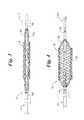
- FIG. 3is a partial plan view of a stent delivery catheter of the present invention, having an expandable wire member region disposed under a stent;
- FIG. 4is a partial plan view of the stent delivery catheter of FIG. 3, wherein the wire member expands causing the radial displacement of the stent.
- FIG. 1shows a partial cross-sectional view of a stent delivery catheter 10 in accordance with the present invention.
- a stent delivery catheter 10that includes a catheter shaft 12 having a proximal end (not shown) and a distal end 14 .
- a plurality of lumensextend within the catheter shaft 12 .
- the various lumensconnect features of the catheter 10 to a source located at the proximal end of the catheter.
- Examples of lumens extending within catheter 10include a guidewire lumen and at least one inflation lumen. In preferred embodiments of the present invention, two or three inflation lumens extend along a portion of the catheter shaft 12 .
- Connection of a lumen with its corresponding sourceis generally accomplished using a manifold positioned on the proximal-most end of the catheter 10 .
- Inflation ports on the manifoldfluidly connect and direct ancillary devices to their corresponding lumens.
- the inflation portspossesses a luer lock fitting on the proximal end of the inflation port that mates with a corresponding connector on the appropriate ancillary device.
- a distal tipthat aids the catheter in navigation through the tortuous vasculature of the patient. Modifications in the shape and size of the distal tip further aid the catheter in crossing stenosed lesions within the vasculature.
- Proximal the distal-most end of catheter 10is an expandable dilation balloon 16 .
- Expandable balloon 16carries an expandable stent 18 that is loaded over the balloon.
- Expandable stent 18 of the present inventionis shown as a wire-like member comprising a plurality of interconnected strut-like members 20 . Strut-like members 20 are fabricated in defined patterns to provide radial expansion.
- the wire-like stent 18expands radially when a pressure is exerted within the inner walls of the stent. Although a wire-like stent is specifically depicted, the use of other expandable stents 18 for intravascular purposes is possible without deviating from the spirit and scope of the present invention.
- the expandable stent 18is loaded over the balloon 16 in a constricted or compacted state.
- the manufacturergenerally loads stent 18 ; however, a member of the surgical, radiology or cardiology staff may additionally load stent 18 within a clinical environment.
- a “compacted configuration”is when stent 18 is crimped upon the catheter 10 so that the stent's profile closely mimics the profile of the catheter shaft 12 .
- An “expanded configuration”is when stent 18 has been radially expanded by inflation of the expandable balloon 16 . It is within the scope of the present invention to have a stent configuration where a portion of the stent is within the compacted configuration, whereas another portion is expanded.
- Expandable balloon 16includes two inflatable members, an inner inflation member 22 and an outer inflation member 24 . Both the inner 22 and outer 24 inflation members are attached to the catheter shaft 12 . Laser, adhesive, hot melt and thermal bonding are all acceptable methods for adhering the inflation members 22 and 24 to the catheter shaft 12 . As their names denote, however, the inner inflation member 22 is positioned under the outer inflation member 24 . The inner inflation member 22 , therefore, is adhered to a portion of the shaft 12 within the area defined by the outer inflation member 24 . Only outer tubular member 24 is in physical contact with the expandable stent 18 . The outer wall of the inner inflation member 22 contacts the inner wall of the outer inflation member 24 .
- Inner inflation member 22is generally shorter in length and inflated height than the outer inflation member 24 .
- the inner inflation member 22has an inflated height equivalent to the inflated height outer inflation member 24 .
- the length of the inner inflation member 22is centered, with respect to the length of the outer tubular member 24 , within the outer inflation member 24 .
- the inner inflation member 22is preferably stretched longitudinally during its mounting and subsequent adherence to the catheter shaft 12 . Stretching the inner inflation member thins the polymeric material, allowing the inner inflation member 22 to burst under pressure when desired, as discussed in detail below.
- Material selection for inner inflation member 22includes those materials having desired expansion and burst pressures.
- the inner inflation member 22therefore, is generally composed of a highly flexible and distensible material.
- Materials suitable for inner inflation member 22include highly flexible polymeric materials.
- the inner inflation member 22is comprised of latex, a polyolefin such as ethylene vinyl acetate (EVA), as well as other suitable thermoplastic elastomers.
- EVAethylene vinyl acetate
- the inner inflation member 22may possess a line of weakness (not shown).
- a line of weaknessincludes a perforation or scoring of the material forming the inner inflation member 22 .
- scoring of the inner inflation member 22 materialis made circumferentially about the inflation member. Circumferential scoring allows the inner inflation member 22 to split radially. Under sufficient pressure, a radial split will cause the perforated inner inflation member 22 to “snap back” away from the center of the inflation member.
- the inner inflation member 22may be scored longitudinally, or at the inflation member's ends. The depth of the scoring must provide a balance between sufficient inflation strength and predictable bursting pressures. In one embodiment, an instrument scoring the inner inflation member 22 at a depth that closely approximates one-third of the inflation member's total wall thickness is proven to provide sufficient inflation and bursting predictability.
- the inner inflation member 22is semi-permeable under certain inflation pressures.
- the walls of a semi-permeable inner inflation member 22may be porous. For example, the sizes of the pores found within the walls of the member dilate with the inflation of the inner inflation member 22 . The pores within the walls are too small to permit significant fluid from escaping under little or no inflation pressure. Under sufficiently high inflation pressures, however, inflation fluid may escape through the dilated pores into the surrounding volume (defined under the outer inflation member 24 ).
- the outer inflation member 24comprises a less flexible and less distensible material than the inner inflation member 22 .
- Materials suitable for the outer inflation member 24include generally noncompliant polymeric materials.
- the outer inflation member 24is comprised of polyether block amide (PEBA), polyethylene, polyethylene terephthalate (PET), as well as other suitable thermoplastic polymers.
- the outer inflation member 24can also comprise semi-compliant polyamides, polyether block amides or nylons, as well as hinged compliant materials such as polybutylene terephthalate (PBT) and Arnitel.
- a series of lumen openings 30 , 32 , 34are depicted along the length of the catheter shaft.
- the number of lumen openings depictedis for illustrative purposes only. The number of lumen openings may vary depending upon the catheter used and the desired application for the catheter.
- the lumen openings in FIG. 1are shown to illustrate possible opening placements and the resulting effects of such placements.
- a first lumen opening 30is positioned under inner inflation member 22 only.
- Two additional lumen openings, 32 and 34are positioned only under the outer inflation member 24 .
- Lumen openings along catheter shaft 12may share a common inflation lumen, or the openings may correspond to individual inflation lumens extending within the catheter shaft 12 .
- Multiple inflation lumenspermit an operator to vary fluid pressures experienced at different regions within the expandable balloon 16 . For example, assuming the two lumen openings 32 and 34 under the outer inflation member 24 are connected, while separate from the lumen opening 30 , an operator may increase the fluid pressure within inner inflation member 22 while at the same time reducing the fluid pressure within outer inflation member 24 . This regulation is all done by controlling the inflation fluid flow rates entering and exiting the corresponding lumen openings.
- Stent movement during deploymentis reduced when the stent 18 is first expanded medially.
- Medial balloon inflationcauses the center of stent 18 to expand first. This initial expansion impinges the center of stent 18 against the surrounding vessel wall and reduces longitudinal displacement during further expansion of the balloon 16 and stent 18 . Additionally, homogeneous expansion of the stent 18 also reduces longitudinal displacement.
- the expandable balloon 16 of the present inventionprovides for either medial or homogeneous expansion of the expandable stent 18 by selectively controlling the inflation fluid pressure and rate of inflation within the various portions of the balloon.
- the inner inflation member 22has at least one dedicated inflation lumen feeding the member.
- An operator of the stent of the present inventionmay inflate only the center of the expandable balloon 16 when desired.
- the operatorfeeds inflation fluid through the appropriate inflation lumen into the inner inflation member 22 .
- the inner inflation member 22then expands, having the uninflated outer inflation member 24 draped over the inner inflation member's profile.
- the center of the stent 18additionally expands roughly following the profile of the inner inflation member 22 , as seen in FIG. 1 .
- the inner inflation member 22is generally expanded until stent 18 engages the surrounding vessel wall. Impinging stent 18 against the vessel wall greatly reduces the possibility of stent displacement along the vessel's longitudinal axis.
- sufficient inflation pressures within the inner inflation member 22may cause the inner inflation member to burst. Bursting pressures generally occur after the inner inflation member 22 can no longer radially inflate (e.g., after the inner inflation member 22 has set stent 18 against the surrounding vessel wall). Confining the expansion of balloon 16 increases internal balloon pressure. The highly flexible and distensible material of the inner inflation member 22 is finally stressed to a bursting point where the member ruptures.
- Rupturing of the inner inflation member 22allows inflation fluid from within the inner inflation member 22 to disperse into the outer inflation member 24 . Additional inflation fluid is then supplied to the outer inflation member 24 to further expand the unexpanded portions of stent 18 .
- the additional inflation fluidmay continue to be supplied through lumen opening 30 , dedicated to the inner inflation lumen, or additional inflation lumens may be used that have lumen openings 32 and 34 dedicated only within the outer inflation member 24 .
- the outer inflation lumen 24is then radially expanded to impinge the remaining portions of stent 18 against the vessel wall.
- An inner inflation member 22 capable of bursting under controlled circumstancesis also useful in drug delivery applications. Therapeutic drugs that treat stenotic lesions often require mixing at the point of delivery. Few methods exist for mixing solutions deep within the vasculature of a patient. The combination of a rupturable inner inflation member 22 with a porous outer inflation member 24 creates an effective device for therapeutic drug treatment.
- one therapeutic drugmay be used to inflate the inner inflation member 22 while a second therapeutic drug is used to partially inflate the outer tubular member 24 .
- a second therapeutic drugis used to partially inflate the outer tubular member 24 .
- the highly flexible and distensible material of the inner inflation member 22ruptures, the bolus of drugs held in the inner inflation member 22 disperses into the outer inflation member 24 .
- the rupturing of the inner inflation member 22causes the two therapeutic drugs to thoroughly mix.
- Increasing the inflation pressure within the outer inflation member 24allows the mixed therapeutic drugs to disperse out of the outer inflation member 24 , and onto the lesion.
- the bursting pressure and/or direction of rupturing experienced by the inner inflation member 22may be controlled through preferential scoring or perforation of the member wall.
- Circumferential scoring of the vessel wallis particularly useful when the lumen opening 30 is centrally positioned under the inner inflation member 22 .
- the combination of proper lumen opening placement and circumferential scoringhelps ensure that lumen opening 30 remains patent after rupturing. Because the circumferential scoring forces a radial split of the inflation member 22 , the resulting “snap back” of the remaining member material away from the center of the inflation member reduces the chance that the balloon will cover the centrally located lumen opening 30 . Maintaining patency of lumen opening 30 is particularly important for deflation purposes.
- Catheter 10must be withdrawn from the patient's vasculature after treatment. In order to withdraw catheter 10 , balloon 16 must first be deflated. The combination of central lumen opening placement and circumferential scoring is believed to enhance the deflation procedure.
- another lumen openingmay be used to deflate the expanded balloon.
- lumen openings 32 and 34positioned only under outer inflation member 24 , can be used to deflate the outer inflation member 24 following completion of the medical procedure.
- a solid rod plugis inserted within a portion of a dormant inflation lumen.
- the solid rod plugcomprises a flexible shaft having a proximal end, a distal end and a length that closely approximates the length of the inflation lumen. Shorter length plugs may also be used.
- the outer diameter of the plug's flexible shaftsealably slides within the inner diameter of the dormant inflation lumen.
- the proximal end of the pluggenerally possesses a luer lock fitting. This luer lock fitting mates and seals with a corresponding luer connector on the inflation port of the catheter manifold.
- the distal end of the plugis advanced through the dormant inflation lumen until the proximal end of the plug connects with the inflation port connector.
- the plugis then sealably connected to the manifold, thereby preventing inflation fluid from escaping through the dormant lumen.
- the plugmay be withdrawn from the lumen, thereby allowing the lumen to be operational for inflation or deflation of expandable balloon 16 .
- a hollow rodmay be inserted within the dormant inflation lumen.
- the hollow rodhas a proximal end, a distal end and a flexible lumen shaft extending the length therethrough.
- the outer diameter of the flexible hollow rodsealably slides within the inner diameter of the dormant inflation lumen.
- the flexible hollow rodgenerally extends the length of the inflation lumen.
- At the proximal end of the hollow rodare matching openings that correspond with the inflation lumen openings, for example 30 , 32 and 34 , which fluidly connect expandable balloon 16 with the inflation lumen. In a first position, the openings within the hollow rod synchronize with the inflation lumen openings. This position allows the hollow rod to be in fluid communication with the expandable balloon 16 .
- the openingsno longer match.
- the lumen wall of the hollow rodsealably obstructs the inflation lumen openings.
- the expandable balloon 16lacks fluid communication with either the hollow rod or the inflation lumen when the hollow rod is rotated into this configuration. Therefore, the openings of the hollow rod must align properly with the inflation lumen openings in order to utilize an inflation lumen having the hollow rod inserted therein.
- the inner inflation member 22comprises a semi-permeable, porous wall material, as described above.
- an inflation fluidis supplied only to the inner inflation member 22 .
- Inner inflation member 22inflates radially, resulting in the medial impingement of stent 18 against the treated vascular wall.
- the inner inflation member 22continues to expand until the internal pressure within the member causes inflation fluid to escape through the member's wall.
- a constant stream of inflation fluid, directed only within inner inflation member 22eventually inflates the outer inflation member 24 .
- additional inflation fluidmay be supplied through lumen openings 32 and 34 , dedicated to the inflation of outer inflation member 24 .
- FIG. 2shows inflation fluid filling both the inner 22 and outer 24 inflation members concurrently. With or without the additional inflation fluid, the outer inflation member 24 eventually expands to impinge the remaining portions of stent 18 against the treated vascular wall.
- inflation fluidis supplied to both the inner inflation member 22 and the outer inflation member 24 concurrently.
- all regions of the expandable balloon 16are inflated concurrently, resulting in the homogenous radial expansion of stent 18 .
- Incorporating a dedicated inflation lumen and inflation member within the center of expandable balloon 16ensures proper medial inflation.
- Providing dedicated inflation lumen openings 32 and 34 within the remaining sections of balloon 16similarly controls inflation within those regions. More specifically to FIG. 2, lumen openings 32 and 34 at the ends of expandable balloon 16 either can share or be individually connected to inflation lumens in order to ensure proper fluid distribution within the balloon.
- stent 18Homogeneous radial expansion of stent 18 occurs when an operator inflates the outer inflation member 24 concurrently with the inner inflation member 22 . Controlling the inflation rates within the expandable balloon 16 causes stent 18 to expand radially in a homogeneous fashion. The stent 18 , therefore, uniformly impinges upon the treated vessel. Uniform impingement greatly reduces the possibility of stent 18 displacing along the vessel's longitudinal axis during deployment.
- FIG. 3shows a stent delivery catheter 10 having an expandable wire member 40 .
- FIG. 3shows a stent delivery catheter 10 that includes a catheter shaft 12 having a proximal end (not shown) and a distal end 14 .
- Catheter shaft 12 in FIG. 3includes at least two tubular members, an outer tubular member 42 and an inner tubular member 44 .
- the inner tubular member 42extends from the proximal-most end of catheter 10 to the distal-most end of catheter 10 .
- the outer tubular member 44is circumferentially disposed over a portion of the inner tubular member 42 .
- the outer tubular member 44extends from the proximal-most end of catheter 10 to a point proximal the distal-most end of catheter 10 .
- the inner tubular member 42 and the outer tubular member 44may be relatively displaced with respect to one another.
- inner tubular member 42may be longitudinally displaced within the outer tubular member 44 .
- An expandable wire member 40spans distally from the distal-most end of outer tubular member 44 to a distal portion of inner tubular member 42 .
- the expandable wire member 40includes a plurality of wire elements 50 that are woven in patterns to provide radial expansion.
- Materials suitable for the wire elements 50include nitinol, stainless steel, and semi-rigid polymeric materials.
- One end of a wire element 50is anchored to the outer tubular member 44 , while the other end is anchored to the inner tubular member 42 .
- a balloon material(not shown) is disposed over the expandable wire member 40 , as with the outer inflation member of previous embodiments.
- an expandable stent 18is loaded upon the expandable wire member 40 .
- the expandable stent 18expands radially when a pressure is exerted from within its inner walls.
- a wire stentis specifically depicted, the use of other stents for intravascular purposes is possible without deviating from the spirit and scope of the present invention.
- wire member 40Longitudinal displacement between the inner 42 and outer 44 tubular members forces wire member 40 to radially expand, as shown in FIG. 4 .
- wire member 40expands first medially, and then from the center outward. Medial expansion of wire member 40 impinges the center of stent 18 into the patient's vascular wall. As with medial inflation, medial expansion of wire member 40 greatly reduces the possibility of stent displacement along the vessel's longitudinal axis. Further longitudinal displacement of the inner 42 and outer 44 tubular members of the catheter shaft permits the wire member 40 to fully expand, thereby impinging the remaining portions of stent 18 against the surrounding vessel wall.
- an expandable balloonmay overlay the wire member 40 of the present invention.
- the expandable ballooncomplements the expansive properties of wire member 40 .
- inflation of the expandable balloon, following medial expansion with wire member 40may further set and impinge stent 18 against the surrounding vascular wall. Balloon inflation generally provides greater uniform pressure on the inner walls of a stent. This increased surface contact aids in stent deployment when particularly difficult stenosed lesions are involved.
Landscapes
- Health & Medical Sciences (AREA)
- Heart & Thoracic Surgery (AREA)
- Engineering & Computer Science (AREA)
- Biomedical Technology (AREA)
- Life Sciences & Earth Sciences (AREA)
- Veterinary Medicine (AREA)
- Animal Behavior & Ethology (AREA)
- Public Health (AREA)
- General Health & Medical Sciences (AREA)
- Cardiology (AREA)
- Oral & Maxillofacial Surgery (AREA)
- Vascular Medicine (AREA)
- Transplantation (AREA)
- Child & Adolescent Psychology (AREA)
- Biophysics (AREA)
- Pulmonology (AREA)
- Anesthesiology (AREA)
- Hematology (AREA)
- Media Introduction/Drainage Providing Device (AREA)
Abstract
Description
Claims (15)
Priority Applications (1)
| Application Number | Priority Date | Filing Date | Title |
|---|---|---|---|
| US09/758,582US6592568B2 (en) | 2001-01-11 | 2001-01-11 | Balloon assembly for stent delivery catheter |
Applications Claiming Priority (1)
| Application Number | Priority Date | Filing Date | Title |
|---|---|---|---|
| US09/758,582US6592568B2 (en) | 2001-01-11 | 2001-01-11 | Balloon assembly for stent delivery catheter |
Publications (2)
| Publication Number | Publication Date |
|---|---|
| US20020091435A1 US20020091435A1 (en) | 2002-07-11 |
| US6592568B2true US6592568B2 (en) | 2003-07-15 |
Family
ID=25052260
Family Applications (1)
| Application Number | Title | Priority Date | Filing Date |
|---|---|---|---|
| US09/758,582Expired - LifetimeUS6592568B2 (en) | 2001-01-11 | 2001-01-11 | Balloon assembly for stent delivery catheter |
Country Status (1)
| Country | Link |
|---|---|
| US (1) | US6592568B2 (en) |
Cited By (39)
| Publication number | Priority date | Publication date | Assignee | Title |
|---|---|---|---|---|
| US20030074044A1 (en)* | 2001-10-16 | 2003-04-17 | Randby John H. | Stent delivery system |
| US20040073251A1 (en)* | 2002-10-15 | 2004-04-15 | Jan Weber | Nanotube paper-based medical device |
| US20040098082A1 (en)* | 1996-08-23 | 2004-05-20 | Scimed Life Systems, Inc. | Catheter support for stent delivery |
| US20040236278A1 (en)* | 2003-05-22 | 2004-11-25 | Atrium Medical Corp. | Therapeutic agent delivery |
| US20040236279A1 (en)* | 2003-05-22 | 2004-11-25 | Atrium Medical Corp. | Gaseous therapeutic agent delivery |
| US20040236410A1 (en)* | 2003-05-22 | 2004-11-25 | Atrium Medical Corp. | Polymeric body formation |
| US20060161102A1 (en)* | 2005-01-18 | 2006-07-20 | Newcomb Kenneth R | Controlled failure balloon catheter assemblies |
| US20060167491A1 (en)* | 2003-01-21 | 2006-07-27 | Wholey Mark H | Vascular catheter with expanded distal tip for receiving a thromboembolic protection device and method of use |
| US20070173785A1 (en)* | 2006-01-24 | 2007-07-26 | Boston Scientific Scimed, Inc. | Flow-inflated diffusion therapeutic delivery |
| US20070207182A1 (en)* | 2006-03-06 | 2007-09-06 | Jan Weber | Medical devices having electrically aligned elongated particles |
| US20070225792A1 (en)* | 2006-03-24 | 2007-09-27 | Juan Granada | Conformable vascular prosthesis delivery system |
| US20080294231A1 (en)* | 2007-05-16 | 2008-11-27 | Boston Scientific Scimed, Inc. | Stent Delivery Catheter |
| WO2006087721A3 (en)* | 2005-02-17 | 2009-04-02 | Nicast Ltd | Inflatable medical device |
| US20090149948A1 (en)* | 2007-09-06 | 2009-06-11 | Boston Scientific Scimed, Inc. | Medical devices containing silicate and carbon particles |
| US20090157048A1 (en)* | 2007-12-18 | 2009-06-18 | Boston Scientific Scimed, Inc. | Spiral cut hypotube |
| US20090177185A1 (en)* | 2008-01-03 | 2009-07-09 | Boston Scientific Scimed, Inc. | Cut tubular members for a medical device and methods for making and using the same |
| US20090312827A1 (en)* | 2005-12-23 | 2009-12-17 | C.R. Bard Inc. | Balloon catheter with centralized vent hole |
| US20100204774A1 (en)* | 2006-03-06 | 2010-08-12 | Boston Scientific Scimed, Inc. | Stent delivery catheter |
| US8292827B2 (en) | 2005-12-12 | 2012-10-23 | Boston Scientific Scimed, Inc. | Micromachined medical devices |
| US8956376B2 (en) | 2011-06-30 | 2015-02-17 | The Spectranetics Corporation | Reentry catheter and method thereof |
| CN104394808A (en)* | 2012-10-01 | 2015-03-04 | C·R·巴德公司 | Balloon catheter with multiple inflated lumens and related methods |
| US8998936B2 (en) | 2011-06-30 | 2015-04-07 | The Spectranetics Corporation | Reentry catheter and method thereof |
| US9339632B2 (en) | 2006-09-27 | 2016-05-17 | Boston Scientific Scimed, Inc. | Catheter shaft designs |
| US20160256303A1 (en)* | 2011-02-08 | 2016-09-08 | Advanced Bifurcation Systems, Inc. | System and Methods for Treating a Bifurcation With a Fully Crimped Stent |
| US9814862B2 (en) | 2011-06-30 | 2017-11-14 | The Spectranetics Corporation | Reentry catheter and method thereof |
| CN107802944A (en)* | 2017-06-01 | 2018-03-16 | 刘逸 | One kind orientation extruding sacculus dilating catheter |
| WO2018218781A1 (en)* | 2017-06-01 | 2018-12-06 | 刘逸 | Directional squeezing balloon dilating catheter |
| US10219927B2 (en) | 2008-09-25 | 2019-03-05 | Advanced Bifurcation Systems Inc. | System and methods for treating a bifurcation |
| US10219926B2 (en) | 2008-09-25 | 2019-03-05 | Advanced Bifurcation Systems Inc. | Selective stent crimping |
| US10406010B2 (en) | 2011-02-08 | 2019-09-10 | Advanced Bifurcation Systems Inc. | Multi-stent and multi-balloon apparatus for treating bifurcations and methods of use |
| US10485949B2 (en) | 2013-04-24 | 2019-11-26 | Loma Vista Medical, Inc. | Inflatable medical balloons with continuous fiber wind |
| US10610391B2 (en) | 2008-09-25 | 2020-04-07 | Advanced Bifurcation Systems Inc. | Stent alignment during treatment of a bifurcation |
| US11000392B2 (en) | 2008-09-25 | 2021-05-11 | Advanced Bifurcation Systems Inc. | Partially crimped stent |
| US11298252B2 (en) | 2008-09-25 | 2022-04-12 | Advanced Bifurcation Systems Inc. | Stent alignment during treatment of a bifurcation |
| US11408573B1 (en) | 2021-09-23 | 2022-08-09 | Blisslights Llc | Optical projection device |
| US12076258B2 (en) | 2008-09-25 | 2024-09-03 | Advanced Bifurcation Systems Inc. | Selective stent crimping |
| EP4501218A2 (en) | 2014-09-17 | 2025-02-05 | Canary Medical Inc. | Devices, systems and methods for using and monitoring medical devices |
| USD1064384S1 (en) | 2022-05-25 | 2025-02-25 | Blisslights Llc | Projection system |
| US12324756B2 (en) | 2008-09-25 | 2025-06-10 | Advanced Bifurcation Systems Inc. | System and methods for treating a bifurcation |
Families Citing this family (10)
| Publication number | Priority date | Publication date | Assignee | Title |
|---|---|---|---|---|
| US7637886B2 (en)* | 1999-01-25 | 2009-12-29 | Atrium Medical Corporation | Expandable fluoropolymer device and method of making |
| US6955661B1 (en) | 1999-01-25 | 2005-10-18 | Atrium Medical Corporation | Expandable fluoropolymer device for delivery of therapeutic agents and method of making |
| ES2260275T3 (en)* | 2000-09-05 | 2006-11-01 | Medevert Limited | BODY CAVITY COATING. |
| US8932340B2 (en)* | 2008-05-29 | 2015-01-13 | Boston Scientific Scimed, Inc. | Bifurcated stent and delivery system |
| US9119716B2 (en)* | 2011-07-27 | 2015-09-01 | Edwards Lifesciences Corporation | Delivery systems for prosthetic heart valve |
| US9402983B1 (en)* | 2012-10-31 | 2016-08-02 | Sainath Intellectual Properties, Llc | Variably expanding balloon catheter |
| EP2929859A1 (en) | 2014-04-10 | 2015-10-14 | Carag AG | A kit for placing a bypass |
| US12397137B2 (en)* | 2020-04-24 | 2025-08-26 | Medtronic Vascular, Inc. | Nested balloon assembly |
| US20210401444A1 (en)* | 2020-06-29 | 2021-12-30 | Neuravi Limited | Isolated stenting with distal balloon |
| CN114469449A (en)* | 2020-10-28 | 2022-05-13 | 爱德华兹生命科学公司 | Protected pressure safety balloon |
Citations (15)
| Publication number | Priority date | Publication date | Assignee | Title |
|---|---|---|---|---|
| US5358487A (en)* | 1993-10-15 | 1994-10-25 | Cordis Corporation | Frangible balloon catheter |
| US5366472A (en) | 1989-06-06 | 1994-11-22 | Cordis Corporation | Dilatation balloon within an elastic sleeve |
| US5409495A (en) | 1993-08-24 | 1995-04-25 | Advanced Cardiovascular Systems, Inc. | Apparatus for uniformly implanting a stent |
| US5470313A (en) | 1994-02-24 | 1995-11-28 | Cardiovascular Dynamics, Inc. | Variable diameter balloon dilatation catheter |
| US5645560A (en) | 1995-12-15 | 1997-07-08 | Cardiovascular Dynamics, Inc. | Fixed focal balloon for interactive angioplasty and stent implantation |
| US5843116A (en) | 1996-05-02 | 1998-12-01 | Cardiovascular Dynamics, Inc. | Focalized intraluminal balloons |
| US5890531A (en) | 1995-04-18 | 1999-04-06 | Noram Engineering And Constructors Ltd. | Apparatus for the self-cleaning of process tubes |
| US5900433A (en)* | 1995-06-23 | 1999-05-04 | Cormedics Corp. | Vascular treatment method and apparatus |
| US6048350A (en) | 1999-06-14 | 2000-04-11 | Scimed Life Systems, Inc. | Segmented balloon delivery system |
| US6120523A (en) | 1994-02-24 | 2000-09-19 | Radiance Medical Systems, Inc. | Focalized intraluminal balloons |
| US6136011A (en)* | 1998-07-14 | 2000-10-24 | Advanced Cardiovascular Systems, Inc. | Stent delivery system and method of use |
| US6200325B1 (en) | 1999-03-31 | 2001-03-13 | Advanced Cardiovascular Systems, Inc. | Balloon catheter and stent deploying catheter system |
| US6290485B1 (en) | 1995-03-02 | 2001-09-18 | Lixiao Wang | Mold for forming a balloon catheter having stepped compliance curve |
| US6293924B1 (en) | 1996-12-12 | 2001-09-25 | Advanced Cardiovascular Systems, Inc. | Balloon assembly with separately inflatable sections |
| US6296660B1 (en) | 1993-09-30 | 2001-10-02 | Boston Scientific Corporation | Controlled deployment of a medical device |
- 2001
- 2001-01-11USUS09/758,582patent/US6592568B2/ennot_activeExpired - Lifetime
Patent Citations (16)
| Publication number | Priority date | Publication date | Assignee | Title |
|---|---|---|---|---|
| US5366472A (en) | 1989-06-06 | 1994-11-22 | Cordis Corporation | Dilatation balloon within an elastic sleeve |
| US5409495A (en) | 1993-08-24 | 1995-04-25 | Advanced Cardiovascular Systems, Inc. | Apparatus for uniformly implanting a stent |
| US6296660B1 (en) | 1993-09-30 | 2001-10-02 | Boston Scientific Corporation | Controlled deployment of a medical device |
| US5358487A (en)* | 1993-10-15 | 1994-10-25 | Cordis Corporation | Frangible balloon catheter |
| US6120523A (en) | 1994-02-24 | 2000-09-19 | Radiance Medical Systems, Inc. | Focalized intraluminal balloons |
| US5470313A (en) | 1994-02-24 | 1995-11-28 | Cardiovascular Dynamics, Inc. | Variable diameter balloon dilatation catheter |
| US6027517A (en) | 1994-02-24 | 2000-02-22 | Radiance Medical Systems, Inc. | Fixed focal balloon for interactive angioplasty and stent implantation catheter with focalized balloon |
| US6290485B1 (en) | 1995-03-02 | 2001-09-18 | Lixiao Wang | Mold for forming a balloon catheter having stepped compliance curve |
| US5890531A (en) | 1995-04-18 | 1999-04-06 | Noram Engineering And Constructors Ltd. | Apparatus for the self-cleaning of process tubes |
| US5900433A (en)* | 1995-06-23 | 1999-05-04 | Cormedics Corp. | Vascular treatment method and apparatus |
| US5645560A (en) | 1995-12-15 | 1997-07-08 | Cardiovascular Dynamics, Inc. | Fixed focal balloon for interactive angioplasty and stent implantation |
| US5843116A (en) | 1996-05-02 | 1998-12-01 | Cardiovascular Dynamics, Inc. | Focalized intraluminal balloons |
| US6293924B1 (en) | 1996-12-12 | 2001-09-25 | Advanced Cardiovascular Systems, Inc. | Balloon assembly with separately inflatable sections |
| US6136011A (en)* | 1998-07-14 | 2000-10-24 | Advanced Cardiovascular Systems, Inc. | Stent delivery system and method of use |
| US6200325B1 (en) | 1999-03-31 | 2001-03-13 | Advanced Cardiovascular Systems, Inc. | Balloon catheter and stent deploying catheter system |
| US6048350A (en) | 1999-06-14 | 2000-04-11 | Scimed Life Systems, Inc. | Segmented balloon delivery system |
Cited By (72)
| Publication number | Priority date | Publication date | Assignee | Title |
|---|---|---|---|---|
| US20040098082A1 (en)* | 1996-08-23 | 2004-05-20 | Scimed Life Systems, Inc. | Catheter support for stent delivery |
| US7749234B2 (en) | 1996-08-23 | 2010-07-06 | Boston Scientific Scimed, Inc. | Catheter support for stent delivery |
| US8152819B2 (en) | 1996-08-23 | 2012-04-10 | Boston Scientific Scimed, Inc. | Catheter support for stent delivery |
| US20030074044A1 (en)* | 2001-10-16 | 2003-04-17 | Randby John H. | Stent delivery system |
| US20040073251A1 (en)* | 2002-10-15 | 2004-04-15 | Jan Weber | Nanotube paper-based medical device |
| US20040138733A1 (en)* | 2002-10-15 | 2004-07-15 | Scimed Life Systems, Inc. | Nano-actuated medical device |
| US7493160B2 (en) | 2002-10-15 | 2009-02-17 | Boston Scientific Scimed, Inc. | Nano-actuated medical device |
| US7037319B2 (en) | 2002-10-15 | 2006-05-02 | Scimed Life Systems, Inc. | Nanotube paper-based medical device |
| US20060167491A1 (en)* | 2003-01-21 | 2006-07-27 | Wholey Mark H | Vascular catheter with expanded distal tip for receiving a thromboembolic protection device and method of use |
| US20040236278A1 (en)* | 2003-05-22 | 2004-11-25 | Atrium Medical Corp. | Therapeutic agent delivery |
| US20040236410A1 (en)* | 2003-05-22 | 2004-11-25 | Atrium Medical Corp. | Polymeric body formation |
| US20040236279A1 (en)* | 2003-05-22 | 2004-11-25 | Atrium Medical Corp. | Gaseous therapeutic agent delivery |
| US20060264823A1 (en)* | 2005-01-18 | 2006-11-23 | Newcomb Kenneth R | Controlled failure balloon catheter assemblies |
| US20060161102A1 (en)* | 2005-01-18 | 2006-07-20 | Newcomb Kenneth R | Controlled failure balloon catheter assemblies |
| US20100331947A1 (en)* | 2005-02-17 | 2010-12-30 | Alon Shalev | Inflatable Medical Device |
| WO2006087721A3 (en)* | 2005-02-17 | 2009-04-02 | Nicast Ltd | Inflatable medical device |
| US8292827B2 (en) | 2005-12-12 | 2012-10-23 | Boston Scientific Scimed, Inc. | Micromachined medical devices |
| US20090312827A1 (en)* | 2005-12-23 | 2009-12-17 | C.R. Bard Inc. | Balloon catheter with centralized vent hole |
| US20070173785A1 (en)* | 2006-01-24 | 2007-07-26 | Boston Scientific Scimed, Inc. | Flow-inflated diffusion therapeutic delivery |
| US8043258B2 (en)* | 2006-01-24 | 2011-10-25 | Boston Scientific Scimed, Inc. | Flow-inflated diffusion therapeutic delivery |
| US20100204774A1 (en)* | 2006-03-06 | 2010-08-12 | Boston Scientific Scimed, Inc. | Stent delivery catheter |
| US20070207182A1 (en)* | 2006-03-06 | 2007-09-06 | Jan Weber | Medical devices having electrically aligned elongated particles |
| WO2007112064A3 (en)* | 2006-03-24 | 2008-12-11 | Prescient Medical Inc | Conformable vascular prosthesis delivery system |
| US20070225792A1 (en)* | 2006-03-24 | 2007-09-27 | Juan Granada | Conformable vascular prosthesis delivery system |
| US10315018B2 (en) | 2006-09-27 | 2019-06-11 | Boston Scientific Scimed Inc. | Catheter shaft designs |
| US9339632B2 (en) | 2006-09-27 | 2016-05-17 | Boston Scientific Scimed, Inc. | Catheter shaft designs |
| US20080294231A1 (en)* | 2007-05-16 | 2008-11-27 | Boston Scientific Scimed, Inc. | Stent Delivery Catheter |
| US7981148B2 (en) | 2007-05-16 | 2011-07-19 | Boston Scientific Scimed, Inc. | Stent delivery catheter |
| US20090149948A1 (en)* | 2007-09-06 | 2009-06-11 | Boston Scientific Scimed, Inc. | Medical devices containing silicate and carbon particles |
| US8480729B2 (en) | 2007-09-06 | 2013-07-09 | Boston Science Scimed, Inc. | Medical devices containing silicate and carbon particles |
| US20090157048A1 (en)* | 2007-12-18 | 2009-06-18 | Boston Scientific Scimed, Inc. | Spiral cut hypotube |
| US9227037B2 (en) | 2008-01-03 | 2016-01-05 | Boston Scientific Scimed, Inc. | Cut tubular members for a medical device and methods for making and using the same |
| US8460213B2 (en) | 2008-01-03 | 2013-06-11 | Boston Scientific Scimed, Inc. | Cut tubular members for a medical device and methods for making and using the same |
| US20090177185A1 (en)* | 2008-01-03 | 2009-07-09 | Boston Scientific Scimed, Inc. | Cut tubular members for a medical device and methods for making and using the same |
| US11839562B2 (en) | 2008-09-25 | 2023-12-12 | Advanced Bifurcation Systems Inc. | Partially crimped stent |
| US10219927B2 (en) | 2008-09-25 | 2019-03-05 | Advanced Bifurcation Systems Inc. | System and methods for treating a bifurcation |
| US12324756B2 (en) | 2008-09-25 | 2025-06-10 | Advanced Bifurcation Systems Inc. | System and methods for treating a bifurcation |
| US10610391B2 (en) | 2008-09-25 | 2020-04-07 | Advanced Bifurcation Systems Inc. | Stent alignment during treatment of a bifurcation |
| US11298252B2 (en) | 2008-09-25 | 2022-04-12 | Advanced Bifurcation Systems Inc. | Stent alignment during treatment of a bifurcation |
| US11426297B2 (en) | 2008-09-25 | 2022-08-30 | Advanced Bifurcation Systems Inc. | Selective stent crimping |
| US12076258B2 (en) | 2008-09-25 | 2024-09-03 | Advanced Bifurcation Systems Inc. | Selective stent crimping |
| US10219926B2 (en) | 2008-09-25 | 2019-03-05 | Advanced Bifurcation Systems Inc. | Selective stent crimping |
| US12042412B2 (en) | 2008-09-25 | 2024-07-23 | Advanced Bifurcation Systems Inc. | Stent alignment during treatment of a bifurcation |
| US10918506B2 (en) | 2008-09-25 | 2021-02-16 | Advanced Bifurcation Systems Inc. | System and methods for treating a bifurcation |
| US11857442B2 (en) | 2008-09-25 | 2024-01-02 | Advanced Bifurcation Systems Inc. | System and methods for treating a bifurcation |
| US11000392B2 (en) | 2008-09-25 | 2021-05-11 | Advanced Bifurcation Systems Inc. | Partially crimped stent |
| US12053400B2 (en) | 2011-02-08 | 2024-08-06 | Advanced Bifurcation Systems Inc. | Multi-stent and multi-balloon apparatus for treating bifurcations and methods of use |
| US10285832B2 (en)* | 2011-02-08 | 2019-05-14 | Advanced Bifurcation Systems Inc. | System and methods for treating a bifurcation with a fully crimped stent |
| US11717428B2 (en) | 2011-02-08 | 2023-08-08 | Advanced Bifurcation Systems Inc. | System and methods for treating a bifurcation with a fully crimped stent |
| US10406010B2 (en) | 2011-02-08 | 2019-09-10 | Advanced Bifurcation Systems Inc. | Multi-stent and multi-balloon apparatus for treating bifurcations and methods of use |
| US11484424B2 (en) | 2011-02-08 | 2022-11-01 | Advanced Bifurcation Systems Inc. | Multi-stent and multi-balloon apparatus for treating bifurcations and methods of use |
| US12263107B2 (en)* | 2011-02-08 | 2025-04-01 | Advanced Bifurcation Systems Inc. | System and methods for treating a bifurcation with a fully crimped stent |
| US20160256303A1 (en)* | 2011-02-08 | 2016-09-08 | Advanced Bifurcation Systems, Inc. | System and Methods for Treating a Bifurcation With a Fully Crimped Stent |
| US12324757B2 (en) | 2011-02-08 | 2025-06-10 | Advanced Bifurcation Systems Inc. | Multi-stent and multi-balloon apparatus for treating bifurcations and methods of use |
| US11000393B2 (en) | 2011-02-08 | 2021-05-11 | Advanced Bifurcation Systems Inc. | System and methods for treating a bifurcation with a fully crimped stent |
| US10709872B2 (en) | 2011-06-30 | 2020-07-14 | The Spectranetics Corporation | Reentry catheter and method thereof |
| US8956376B2 (en) | 2011-06-30 | 2015-02-17 | The Spectranetics Corporation | Reentry catheter and method thereof |
| US10603467B2 (en) | 2011-06-30 | 2020-03-31 | The Spectranetics Corporation | Reentry catheter and method thereof |
| US8998936B2 (en) | 2011-06-30 | 2015-04-07 | The Spectranetics Corporation | Reentry catheter and method thereof |
| US10183151B2 (en) | 2011-06-30 | 2019-01-22 | Spectranetics Corporation | Reentry catheter and method thereof |
| US9408998B2 (en) | 2011-06-30 | 2016-08-09 | The Spectranetics Corporation | Reentry catheter and method thereof |
| US9814862B2 (en) | 2011-06-30 | 2017-11-14 | The Spectranetics Corporation | Reentry catheter and method thereof |
| US9775969B2 (en) | 2011-06-30 | 2017-10-03 | The Spectranetics Corporation | Reentry catheter and method thereof |
| US9572960B2 (en)* | 2012-10-01 | 2017-02-21 | C.R. Bard, Inc. | Balloon catheter having multiple inflation lumens and related methods |
| US20150224290A1 (en)* | 2012-10-01 | 2015-08-13 | C.R. Bard, Inc. | Balloon catheter having multiple inflation lumens and related methods |
| CN104394808A (en)* | 2012-10-01 | 2015-03-04 | C·R·巴德公司 | Balloon catheter with multiple inflated lumens and related methods |
| US10485949B2 (en) | 2013-04-24 | 2019-11-26 | Loma Vista Medical, Inc. | Inflatable medical balloons with continuous fiber wind |
| EP4501218A2 (en) | 2014-09-17 | 2025-02-05 | Canary Medical Inc. | Devices, systems and methods for using and monitoring medical devices |
| CN107802944A (en)* | 2017-06-01 | 2018-03-16 | 刘逸 | One kind orientation extruding sacculus dilating catheter |
| WO2018218781A1 (en)* | 2017-06-01 | 2018-12-06 | 刘逸 | Directional squeezing balloon dilating catheter |
| US11408573B1 (en) | 2021-09-23 | 2022-08-09 | Blisslights Llc | Optical projection device |
| USD1064384S1 (en) | 2022-05-25 | 2025-02-25 | Blisslights Llc | Projection system |
Also Published As
| Publication number | Publication date |
|---|---|
| US20020091435A1 (en) | 2002-07-11 |
Similar Documents
| Publication | Publication Date | Title |
|---|---|---|
| US6592568B2 (en) | Balloon assembly for stent delivery catheter | |
| US6136011A (en) | Stent delivery system and method of use | |
| EP1214116B1 (en) | Stent delivery assembly and method of attaching a stent to a catheter balloon | |
| US6491711B1 (en) | Balloon catheter with non-circular balloon taper and method of use | |
| US5788708A (en) | Multiple balloon stent delivery catheter and method | |
| US5954693A (en) | Replenishable stent and delivery system | |
| US4787388A (en) | Method for opening constricted regions in the cardiovascular system | |
| EP0767685B1 (en) | Catheter assembly | |
| JP3631139B2 (en) | Bifurcated catheter assembly | |
| CA2633854C (en) | Balloon catheter with centralized vent hole | |
| US20040210191A1 (en) | Drug delivery balloon catheter | |
| EP2197507B1 (en) | Lamellar shaped layers in medical devices | |
| JP2008541936A (en) | In vivo stent formation | |
| JP2002520095A (en) | Balloon catheter inflating balloon at distal end of balloon and stent delivery system | |
| JP2008519612A (en) | Catheter balloon system and method | |
| EP1796586A1 (en) | Vessel isolation device | |
| US20200146858A1 (en) | Dual balloon catheters and methods for use | |
| AU2001292628A1 (en) | Method and device to do arteriographies and angiographies with a balloon without injecting contrast media in the vessel lumen | |
| WO2002051490A1 (en) | Balloon for a balloon dilation catheter and stent implantation | |
| JP2003523268A (en) | Stent delivery balloon having stent fixing means | |
| US20040102832A1 (en) | Stent delivery and retention apparatus | |
| US20070235899A1 (en) | Dimple Forming Process for Stent Deployment Balloon | |
| JP2002502677A (en) | Radiation delivery catheter with hemoperfusion capability | |
| JP2022521269A (en) | Pressure variable artery balloon |
Legal Events
| Date | Code | Title | Description |
|---|---|---|---|
| AS | Assignment | Owner name:SCIMED LIFE SYSTEMS, INC., MINNESOTA Free format text:ASSIGNMENT OF ASSIGNORS INTEREST;ASSIGNOR:CAMPBELL, ANDREW J.;REEL/FRAME:011786/0606 Effective date:20010104 | |
| FEPP | Fee payment procedure | Free format text:PAYOR NUMBER ASSIGNED (ORIGINAL EVENT CODE: ASPN); ENTITY STATUS OF PATENT OWNER: LARGE ENTITY Free format text:PAYER NUMBER DE-ASSIGNED (ORIGINAL EVENT CODE: RMPN); ENTITY STATUS OF PATENT OWNER: LARGE ENTITY | |
| STCF | Information on status: patent grant | Free format text:PATENTED CASE | |
| AS | Assignment | Owner name:BOSTON SCIENTIFIC SCIMED, INC., MINNESOTA Free format text:CHANGE OF NAME;ASSIGNOR:SCIMED LIFE SYSTEMS, INC.;REEL/FRAME:018505/0868 Effective date:20050101 Owner name:BOSTON SCIENTIFIC SCIMED, INC.,MINNESOTA Free format text:CHANGE OF NAME;ASSIGNOR:SCIMED LIFE SYSTEMS, INC.;REEL/FRAME:018505/0868 Effective date:20050101 | |
| FPAY | Fee payment | Year of fee payment:4 | |
| FPAY | Fee payment | Year of fee payment:8 | |
| FPAY | Fee payment | Year of fee payment:12 |