US6592543B1 - Fluid flow regulator for a smoke evacuation system and method of using same - Google Patents
Fluid flow regulator for a smoke evacuation system and method of using sameDownload PDFInfo
- Publication number
- US6592543B1 US6592543B1US10/116,467US11646702AUS6592543B1US 6592543 B1US6592543 B1US 6592543B1US 11646702 AUS11646702 AUS 11646702AUS 6592543 B1US6592543 B1US 6592543B1
- Authority
- US
- United States
- Prior art keywords
- fluid flow
- flow regulator
- smoke
- fluid
- surgical site
- Prior art date
- Legal status (The legal status is an assumption and is not a legal conclusion. Google has not performed a legal analysis and makes no representation as to the accuracy of the status listed.)
- Expired - Lifetime
Links
Images


Classifications
- A—HUMAN NECESSITIES
- A61—MEDICAL OR VETERINARY SCIENCE; HYGIENE
- A61B—DIAGNOSIS; SURGERY; IDENTIFICATION
- A61B18/00—Surgical instruments, devices or methods for transferring non-mechanical forms of energy to or from the body
- A—HUMAN NECESSITIES
- A61—MEDICAL OR VETERINARY SCIENCE; HYGIENE
- A61B—DIAGNOSIS; SURGERY; IDENTIFICATION
- A61B2218/00—Details of surgical instruments, devices or methods for transferring non-mechanical forms of energy to or from the body
- A61B2218/001—Details of surgical instruments, devices or methods for transferring non-mechanical forms of energy to or from the body having means for irrigation and/or aspiration of substances to and/or from the surgical site
- A61B2218/007—Aspiration
- A61B2218/008—Aspiration for smoke evacuation
- A—HUMAN NECESSITIES
- A61—MEDICAL OR VETERINARY SCIENCE; HYGIENE
- A61M—DEVICES FOR INTRODUCING MEDIA INTO, OR ONTO, THE BODY; DEVICES FOR TRANSDUCING BODY MEDIA OR FOR TAKING MEDIA FROM THE BODY; DEVICES FOR PRODUCING OR ENDING SLEEP OR STUPOR
- A61M13/00—Insufflators for therapeutic or disinfectant purposes, i.e. devices for blowing a gas, powder or vapour into the body
- A61M13/003—Blowing gases other than for carrying powders, e.g. for inflating, dilating or rinsing
Definitions
- the present inventionpertains to the field of the regulation of fluid being expelled from a surgical site. More particularly, the invention relates to a fluid flow regulator, which when used, regulates the flow of fluid from the surgical site and serves as a passive smoke evacuation system for a pressurized surgical site.
- Minimally-invasive surgical proceduressuch as laparoscopic or endoscopic surgery have become increasingly common due to the fact that the procedures generally result in shorter recovery times, less side effects including secondary infections, shorter operating durations, and reduced costs.
- endoscopicencompasses arthroscopic, laparoscopic, hysteroscopic, thoracoscopic or any other similar closed surgical procedures performed with instruments inserted through small, artificially created openings or portals in the patient.
- a first minimally-invasive surgery access portis formed in the patient's abdomen using a Veress needle to puncture the lapra or abdomen.
- An insufflator gassuch as carbon dioxide is injected into the abdomen to distend the pneumoperitoneum, thereby creating an air space or cavity in proximity to the organs on which the surgical operation is to be performed.
- the cavityprovides the work space necessary for the surgeon to maneuver the surgical instruments and endoscope, which are typically introduced into the surgical site through other access ports created by the surgeon.
- the insufflation gasis forced into the surgical site such as the abdominal cavity under pressure by an insufflation device.
- a number of insufflation deviceshave two modes of operation, initiation mode and maintenance mode.
- the initiation modepumps gas at a high rate in order to quickly distend the pneumoperitoneum.
- the maintenance modethe insufflation gas is pumped at a rate up to a maximum pressure to replace the amount of gas lost during the procedure.
- Many insufflation devicesare capable of delivering a maximum flow rate of approximately 16 to 25 liters per minute.
- the maintenance pressure held at the surgical site by the insufflation devicewill vary depending on the insufflation gas and the patient's weight for example.
- An obese patientwill require a higher abdominal pressure in order to distend the pneumoperitoneum the same distance as that of a thinner patient.
- an endoscope coupled to a television monitoris inserted into the abdominal cavity to visualize the interior of the surgical entry.
- medical interventionincluding conventional invasive surgery may be required to control the hemorrhaging.
- the endoscoperemains in the portal which is conventionally dedicated for that instrument. Additional portals are created to provide access for other surgical instruments including probes and other surgical devices that are individually inserted through other cannulas.
- Surgical smokegenerally refers to gases or aerosols that may contain toxins, particulate matter, irritants, viable cells and viruses, water vapor, and other undesirable contaminants.
- the surgical smokepresent a health risk to the patient and complicates the surgical procedure.
- the surgical smokemay be absorbed by the patient through the pneumoperitoneum and will obscure the surgeon's visibility of the surgical field. Outside the patient, the smoke poses a health risk to the surgical personnel if not properly filtered.
- Still another category of prior art smoke evacuation systemsincludes strictly passive filtration systems that avoid the use of vacuum.
- U.S. Pat. No. 6,110,259 to Schultz and PCT application no. PCT/US99/28204 to Boothwhich are both incorporated in their entirety by reference, operate solely in response to the pressure differential created by the surgical site and ambient air.
- Schultzdiscloses a smoke filter and fluid conduit operatively coupled to a pressurized surgical site wherein the fluid flow rate is determined by the inherent properties of the filter media and the ‘substantially unobstructed fluid flow path’ through the fluid conduit.
- Schultzasserts that his invention eliminates the dependency on a vacuum source and combination of ‘flow restrictors or reducers’ and filters.
- the Schultz smoke evacuation systemconsisting only of a filter and fluid conduit teaches away from the use of multiple, in-line structures (filters, resistors, etc.) for stepping or reducing suction whose presence would avoid the simplicity cited as an advantage.
- the Schultz smoke evacuation systemrequires a stopcock to start and stop the fluid flow through the system.
- the stopcockremains in the closed position prior and during the application of the laser, electrocautery device, or ultrasonic scalpels, thereby preventing the escape of any smoke from the surgical site.
- the stopcockis only opened after the surgical site becomes has saturated with smoke that visibility is impaired.
- the stopcockis then turned to the full open position, at which point the pneumoperitoneum is rapidly deflated and the surgical smoke passed through the filter.
- the stopcockPrior to any further surgery, the stopcock is again closed and the pneumoperitoneum re-pressurized by insufflation device, which may take uncomfortably long period of time.
- the process of evacuating the smoke and reinflating the pneumoperitoneummay be repeated numerous times during the laparoscopic procedure.
- a significant disadvantage of the Schultz systemis that the ability of the surgeon to visualize the surgical site and proceed with surgery is significantly hampered during the period that the smoke is evacuated and the pneumoperitoneum distended again. Not only is it inconvenient, but is poses a risk to the patient. More specifically, the surgeon is prevented from observing or intervening on behalf of a patient that is experience internal hemorrhaging, for example, while repeatedly inflating and evacuating the pneumoperitoneum.
- Boothdiscloses a flow control device interposed between the surgical site and the smoke evacuation filter. Although the character of the flow control device is unspecified it would appear to be a form of stopcock consistent with the mechanism shown by Schultz. As such, the Booth device suffers the same drawbacks as the Schultz invention.
- the present inventionovercomes the limitations of the prior art with a fluid flow regulator which, when operatively integrated into a passive smoke evacuation system, regulates the flow rate to permit the continuous evacuation of surgical smoke without deflating the pressurized surgical site.
- the optimal evacuation flow ratewhich is approximately 0.5 to 6.5 liters per minute, maintains the pneumoperitoneum in a distended position continuously through the duration of the laparoscopic procedure, permitting the surgical procedure to be conducted without interruption necessitated by deflation of the pneumoperitoneum used to smoke evacuation and subsequent reinflation.
- the fluid flow regulator of the present inventionis comprised of (i) a flow regulating means for providing a predetermined resistance to the flow of fluid, the appropriate resistance determined as a function of system variables including the resistance of the filtration system and (ii) at least one fluid conduit connecting means for coupling the flow regulating means to the smoke filtration system.
- the fluid flow regulatormay be coupled to the downstream side of the smoke filtration system or, alternatively, between the filter and the surgical site.
- the flow regulating meansis comprised of a diaphragm with at least one orifice of predetermined diameter, the diameter of the orifice restricting the flow of gas expelled from the surgical site within a range sufficient to effectively evacuate surgical smoke without deflating the pneumoperitoneum.
- the fluid flow regulatormay be detachable from the smoke filtration system, thereby allowing one to select the flow regulator of appropriate resistance without replacing the filter itself.
- the flow regulating meansincludes means for attaching a suction device to accelerate the evacuation of smoke when desirable.
- the orificehas an effective diameter of 0.5 to 5 millimeters, although this is subject to vary depending on the fluid flow resistance provided by the other components of the smoke evacuation system, namely the diameter of the cannula, the length and diameter of any conduits, and the resistance afforded by the filtration system itself.
- the fluid flow regulatorincludes a system of flow regulating means which may include, for example, a plurality of differently sized orifices which may be operatively coupled to the filtration system to provide an optimal fluid flow independent of the system variables.
- the system variables that may influence the selection of the proper orificeinclude the pressure at the surgical site, the insufflation gas, the amount of smoke generated, the resistance provided by the various components of the evacuation system.
- the plurality of orificesmay be integrated into a single article of manufacture or apparatus to provide versatility and convenience to the surgeon.
- the inventionmay also be characterized by a novel combination of steps.
- the method of using a fluid flow regulator in a minimally-invasive surgical procedureis comprised of the steps of (i) selecting the appropriate fluid flow regulator in consideration of the limitations described herein; (ii) operatively coupling the fluid flow regulator and smoke filtration system to a surgical site; (iii) pressurizing the surgical site with insufflation gas to distend the pneumoperitoneum; (iv) maintaining the distension of the pneumoperitoneum at a substantially constant position during the surgical procedure by simultaneously replenishing the surgical site with insufflation gas and continuously evacuating insufflation gas and/or surgical smoke through the smoke filtration system at a fluid flow rate substantially equal to the rate for replenishing the surgical site; and (v) evacuating the insufflation gas and surgical smoke at the conclusion of the minimally-invasive surgical procedure.
- the fluid flow regulatormay be used to limit or otherwise regulate the flow of fluid from the surgical site to fundamentally alter practice of laparoscopic surgery.
- application of the fluid flow regulatorallows surgical smoke to be continuously evacuated from the surgical site without the need to interrupt the procedure to deflate the pneumoperitoneum and remove smoke. This additional step present in prior art systems prolongs the procedure and puts the patient at unnecessary risk for the period of time necessary to re-inflate and reestablish visual contact with the surgical site.
- the present inventionreduces the risk to patients, reduces the time necessary to perform surgical procedures, reduces unnecessary manipulation of the smoke evacuation system as compared to prior art systems, namely Schultz and Booth. Also, the present invention provides a truly passive pressure maintenance system with little or no intervention or adjustment necessary by operating personnel.
- FIG. 1is a schematic diagram of a smoke evacuation system of the present invention.
- FIG. 2is an isometric view of the fluid flow regulator of the first preferred embodiment of the present invention.
- FIG. 3is a cross-sectional view of the fluid flow regulator of the first preferred embodiment of the present invention.
- FIG. 4is a cross-sectional view of the fluid flow regulator of the first preferred embodiment operatively coupled to a smoke evacuation filter.
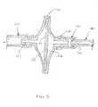
- FIG. 5is a cross-sectional view of the fluid flow regulator of the first preferred embodiment operatively coupled to a smoke evacuation filter and vacuum.
- FIG. 6is an isometric view of the fluid flow regulator of the second preferred embodiment of the present invention.
- FIG. 7is a plan view of the fluid flow regulator of the third preferred embodiment of the present invention.
- FIG. 8is a cross-sectional view of the fluid flow regulator of the third preferred embodiment of the present invention.
- FIG. 9is a flow chart of the method of using the fluid flow regulator of the present invention.
- the present inventionpertains to a fluid flow regulator permitting which, when operatively coupled to a passive filtration system, provides an apparatus and method for optimizing the fluid flow rate evacuated from a laparoscopic surgical site, thereby permitting the continuous evacuation of surgical smoke without deflating the pressurized surgical site.
- the smoke evacuation system in this embodimentis comprised of a trocar assembly 170 , a smoke filtration system 150 , and a fluid flow regulator 100 .
- the trocar assembly 170well known in the prior art is comprised of a cannula 171 with a removable faceted tip 172 for making a surgical incision, a stopcock 173 , and a connector 174 for operationally coupling the insufflation device (not shown) to the surgical site.
- the trocar assembly 170varies in size, shape, and configuration depending on the manufacturer and the functional requirements of the surgical procedure. Although commonly used, a direct fluid connection or Veress needle may be provided in place of the trocar assembly 170 .
- the smoke evacuation systemalso includes a smoke filtration system for filtering the various contaminates in the fluid aspirated from the surgical site.
- the smoke filtration system 150includes a filter adapted to remove the surgical smoke including contaminates and water vapor present in the aspirated fluid.
- the filter 150is adapted to be operably coupled to the surgical site and may include, for example, a flexible hose 160 .
- the trocar assembly 170 and smoke filtration system 150may be coupled by connectors 161 and 174 adapted to detachably engage one another. Suitable connectors include push-on type connectors, such as hose barbs, and screw-on type connectors, such as luer locks.
- the fluid flow regulator 100is comprised of a flow regulating means, a housing 101 , and a fluid conduit connecting means.
- the purpose of the flow regulating meansis to provide a barrier that limits, without entirely stopping, the flow of fluid expelled from the smoke evacuation system.
- the flow regulating meansin the preferred embodiment a diaphragm 102 with a substantially circular orifice 103 having a characteristic diameter.
- the orifice 103is one of numerous features or constructions, which when combined with a substantially unobstructed fluid conduit (introduced below) coupled to the filter 150 , offers a significant obstruction to the free flow of fluid through the filter.
- a significant obstructionis a deliberate impediment to the flow of fluid used to provide a pressure drop beyond that afforded by the unconstricted fluid conduit 160 that operatively couples the filter 150 to the surgical site.
- the diameter of the orifice 103 of the this embodimentis subject to variation depending on pressure at the surgical site, the desired fluid flow rate through the smoke evacuation system, the pressure drop across the various components of the smoke evacuation system, as well as the insufflation gas.
- the diameterranges between 0.5 millimeters and 5 millimeters.
- the area of the orifice 103will vary if a shape other than a circle is implemented.
- the fluid conduit connecting meansis a device for coupling the flow regulating means to smoke filtration system without any substantial loss of gas.
- the flow regulating meansincludes a cylindrical-shaped housing 101 and boss 104 that protrudes from the inner surface 106 , both of which are composed of an elastic material.
- the housing 101 and boss 104constitute the female end of a hose barb connection adapted to stretch over and frictionally engage a male hose barb connector.
- the elasticity of the conduit connecting meansis determined in part by the material from which it is made.
- the conduit connecting meansis manufactured from an elastomer, although one skilled in the art will recognize that a number of alternative materials would also be suitable with appropriate modification of the size and thickness of the structural elements.
- various connectorsincluding push-on type connectors and threaded connections including luer locks may be adapted to couple the fluid flow regulator 100 to the smoke filter 150 .
- the fluid flow regulator 100may be manufactured as an integral, non-detachable component of the filter 150 .
- the fluid flow regulator 100is illustrated on the downstream side of the filter 150 where it is in fluid communication with the posterior filter chamber 155 .
- the anterior filter chamber 151On the opposite side of the filter media 152 is the anterior filter chamber 151 which is in fluid communication with the surgical site, either directly or indirectly by means of a conduit 160 and optional trocar assembly 170 .
- a fluid flow regulator with appropriate modificationmay be inserted between the trocar assembly 170 and the smoke filtration system 150 with no loss of performance or function.
- FIG. 5a cross-sectional view of the fluid flow regulator of the first preferred embodiment operatively coupled to a smoke evacuation filter and vacuum is illustrated.
- the diaphragm 102is made of an elastic material permitting the orifice 103 to stretch and engage a source of vacuum 180 .
- An elastic diaphragmhas the advantage of allowing the surgeon to temporarily attach and then disengage the vacuum 180 to accelerate the removal of surgical smoke or deflation of the pneumoperitoneum.
- the vacuum source 180may ultimately be derived from a wall outlet and may be a cannular type device with manually operated values for controlling the application of negative pressure. In the alternative, the vacuum source 180 may be a pump programmed to apply vacuum automatically or under the control determined by the surgical staff.
- an individual fluid flow regulator 100is one element of a system comprising a plurality of individual fluid flow regulators, each fluid flow regulator providing a different fluid flow resistance for a given pressure differential or flow rate.
- the variation in fluid flow resistanceis achieved by varying the diameter of the orifice 103 between the individual fluid flow regulators.
- systemmay comprise three fluid flow regulators having orifice diameters of 0.5, 1.0, and 2.0 millimeters.
- one of the plurality of fluid flow regulatorswill provide an optimal fluid flow rate in consideration of the pressure at the surgical site, the fluid resistance present by the entire smoke evacuation system, the desired fluid flow rate through the smoke evacuation system, and to a lesser degree, the particular insufflation gas.
- an obese patientmay require a higher surgical site pressure which would give rise to a high fluid flow rate through the filter if not compensated.
- a flow regulator with a relatively high resistancei.e. the smallest diameter orifice, would be required to increase the overall resistance of the smoke filtration system reduce or otherwise limit the fluid flow through the system.
- a relatively thin patientmay require a relatively low surgical site pressure, which would give rise to a low fluid flow rate through filter all things being equal.
- a flow regulator with a relatively low resistance, i.e. the largest diameter orificewould be required to hold the overall resistance of the smoke filtration system low and so as not to further impede the fluid flow through the system.
- the flow regulating system 600is comprised of a plurality of independently operable fluid flow regulating units consistent with that described in the first preferred embodiment.
- the unitsare comprised of substantially identical housings 613 , 623 , 633 , each housing having a corresponding fluid flow regulating means comprised in this embodiment of a diaphragm 611 , 621 , 631 with a unique orifice 612 , 622 , 632 .
- the housings 613 , 623 , 633further include one of a variety of conduit connecting means as described above.
- the attaching means 601affixes the plurality of flow regulating units together, thus providing a simple and cost effective device for regulating the flow through the filter 150 which if necessary may be rapidly and conveniently detached from a smoke filtering system and reattached at a different unit to provide a different fluid flow resistance.
- the fluid flow resistance provided by each of the plurality of flow regulating unitsis different from the other units.
- the fluid flow resistance provided by each unit, as determined by the corresponding orifice,is specifically configured to regulate the fluid flow through the smoke evacuation system for a set of pre-determined or “a priori” system variables, including but not limited to the desired surgical site pressure, desired fluid flow rate, resistance of the individual elements of the smoke evacuation system, and particular insufflation gas.
- the minimum and maximum flow resistance provided by the flow regulating systempreferably corresponds to the minimum and maximum pressure drop necessary to achieve a desired fluid flow rate as a function of the system variables introduced above.
- the resistance of the intermediate unitsis, preferably, selected to provide incremental differences in resistance in approximately equal units scaled between the maximum and minimum resistance.
- the desired surgical site pressurebeing a function of the patient weight, may be estimated in advance of the laparoscopic procedure.
- the desired flow ratemay also be predetermined and will depend to some degree on the surgical device use and the tissue to be treated. For example, the ablation of fatty tissue with a laser creates a relatively large amount of smoke and would dictate a relatively high fluid flow rate.
- These and other variablesmay be charted against the fluid flow resistance of the smoke evacuation system.
- a chart or look-up-tablemay be generated to provide a simple and convenient way for the surgeon to estimate the appropriate unit of the plurality of flow regulating units 610 , 620 , 630 to operatively couple to the smoking filtrations system to achieve the desired flow rate.
- This inventiontherefore, provides a means to accurately “tune in” the optimal fluid flow resistance based upon a priori knowledge of the system variable without the need to swap the filter as Schultz would suggest.
- the fluid flow regulator 700is comprised of a fluid conduit connecting means 703 and a plurality of flow regulating means for providing a predetermined resistance to the flow of fluid.
- the conduit connecting means 703is comprised in this embodiment of an elastic housing 705 and boss 704 that protrude from the interior face of the housing 705 to engage the hose barb of a filtration system.
- the conduit connecting means 703which may operate identically to the conduit connecting means of the first preferred embodiment, holds the fluid flow regulator and the primary orifice 706 of the first disk 701 in operational engagement to the smoke filtration system.
- Alternative conduit connecting means discussed abovewould also be suitable if properly adapted to couple with the filtration system.
- the flow regulating meansin general, may be comprised of the plurality of isolated secondary orifices, each secondary orifice providing a different fluid flow restriction.
- the flow regulating meansis comprised of three secondary orifices 710 , 720 , 730 that populate a second disk 702 .
- Each of the three orificesis isolated from the other two orifices by means of the O-rings 711 , 721 , 731 that substantially prohibit the fluid flow from escaping by means other than the intended secondary orifice.
- the secondary orifice coinciding with the primary orifice 706is in fluid communication with the filtration system.
- orifice 710 as illustratedis in fluid communication with the primary orifice 706 and the surgical site indirectly. Only one of the secondary orifices is in fluid communication with the filtration system at any given time.
- the secondary orifice in communication with the primary orifice 706may be changed by rotating the second disk 702 relative to the first disk 701 about the axis 709 until a difference secondary orifice is aligned with the primary orifice 706 .
- the first and second disks 701 , 702are held in slidable engagement by means of the first and second mating edges 707 and 708 .
- the three orifices 710 , 720 , 730 illustrated in this embodimenthave diameters chosen to regulate the fluid flow through the smoke evacuation system for a set of pre-determined set of system variables, including but not limited to the desired surgical site pressure, desired fluid flow rate, pressure drop across the individual elements of the smoke evacuation system, and particular insufflation gas.
- the minimum and maximum flow resistance provided by the flow regulating systempreferably corresponds to the minimum and maximum pressure drop necessary to achieve a desired fluid flow rate as a function of the system variables introduced above.
- the resistance of the intermediate unitsis, preferably, selected to provide incremental differences in resistance in approximately equal units scaled between the maximum and minimum resistance.
- Representative orifices diametersmay be 0.5, 1.0, and 2.0 millimeters.
- the fluid flow regulating meansmay comprise a system of smaller, more restrictive orifices than that provided by the three orifices 710 , 720 , 730 .
- Equivalent fluid flow resistancemay be achieved by using a plurality of smaller diameter orifices that conduct fluid through the secondary disk 702 .
- the plurality of “petite” orificesif confined to the region in the interior space defined by the corresponding O-ring, may collectively provide the same flow resistance and therefore fluid flow as an individual orifice represent by orifices 710 , 720 , 730 , for example.
- the fluid flow regulatoris comprised of variable fluid flow regulating means and a fluid conduit connecting means for operatively engaging the variable fluid flow regulating means to the smoke filtration system.
- the purpose of the variable fluid flow regulating meansis to provide variable fluid flow resistance for use in concert a passive smoke evacuation system.
- variable fluid flow regulating meansmay be based upon known gas value systems.
- the critical difference between the variable fluid flow regulating means and the prior artis the presence of flow restriction indicia in proximity to the knob, lever, or tuning device for adjusting the resistance of the valve.
- the flow restriction indiciaare distinctive markings, not unlike calibration markings, on the variable fluid flow regulating means that are proportional or otherwise quantitatively related to the fluid flow resistance provided by the variable fluid flow regulating means.
- the flow restriction indiciamay be used with a priori knowledge of the system variables to “predetermine” or otherwise “pre-set” the appropriate variable fluid flow regulating means necessary to achieve the optimum fluid flow rate through the smoke evacuation system.
- the optimum fluid flow rateis within a range sufficient to maintain the pneumoperitoneum in a distended position without deflation. According to the present invention, the optimum fluid flow rate may be maintained throughout the surgical procedure without interruption. Proper selection of the fluid flow resistance permits a surgeon to perform the surgical procedure with the trocar assembly stopcock 173 in the full-on position through the entire surgical procedure without intervention or periodic cycling required in prior art systems.
- the a priori informationincludes but is not limited to the desired surgical site pressure, desired fluid flow rate, pressure drop across the individual elements of the smoke evacuation system, and particular insufflation gas.
- This informationmay be charted against the fluid flow resistance of the smoke evacuation system, including the smoke filtration system and trocar assembly, to predetermine the optimal setting for the variable fluid flow regulating means.
- a chart or look-up-table, LOCmay be generated to provide a simple and convenient way for the surgeon to estimate the appropriate unit of the plurality of units in the flow regulating system to operatively couple to the smoking filtrations system.
- another aspect of the present inventionis the novel method of use of a fluid flow regulator to regulate the flow of fluid in a passive smoke evacuation system.
- the method of using the fluid flow regulator of the present inventionpreferably pertains to various minimally invasive surgical procedures and is comprised of the steps described below.
- the first step 901is to select a fluid flow regulator which, when operatively coupled to a smoke filtration system and the pressurized surgical site restricts the flow of fluid from the surgical site at a rate less than the maximum rate at which the insufflation device can replenish the gas.
- a fluid flow regulatorwhich, when operatively coupled to a smoke filtration system and the pressurized surgical site restricts the flow of fluid from the surgical site at a rate less than the maximum rate at which the insufflation device can replenish the gas.
- many modem insufflation devicescan supply insufflation gas at a rate of 16 to 25 liters per minute, this rate may be excessive and lead to the dehydration and cooling of the patient.
- the flow regulator in combination with the smoke filtration system and trocar assembly 170gives rise to a fluid flow rate of between 1 and 6.5 liters per minute through the smoke filtration system.
- the preferable fluid flow rateis that fluid flow rate induced as a result of the pressure differential arising from the pressurized surgical site and the
- the first step 901implicitly includes the selection of the proper fluid flow setting predetermined that results in the optimal fluid flow rate.
- the second step 902is to operatively couple the fluid flow regulator selected in the previous step 901 and smoke filtration system to a surgical site.
- the fluid flow regulatoris operatively coupled when connected in such a manner as to permit the discharge of fluid from the surgical site through the smoke filtration system.
- the connectionmay include a trocar assembly or, in the alternative, a direct connection provided by a Vereese needle, for example.
- the stopcock 173 on the trocar assembly 170is preferably set to the closed position prior to achieving the maintenance pressure necessary to distend the abdominal cavity.
- the third step 903involves the pressurization of the surgical site with insufflation gas to distend the pneumoperitoneum.
- the distentionshould be sufficient to create a cavity large enough to permit the entry and utilization of laparoscopic and endoscopic instruments.
- the pressurization step 903may occur prior to or simultaneously with the prior two steps 901 , 902 .
- the fourth step 904is to maintain the distension of the pneumoperitoneum at a substantially constant position throughout the surgical procedure.
- the distention of the pneumoperitoneummay be achieved by simultaneously replenishing the insufflation gas and evacuating the insufflation gas/surgical smoke at the surgical site.
- the step of replenishing 905 the surgical site with insufflation gasis performed by the insufflation device, which is preferably programmed to supply the gas at a constant rate. For safety reasons, the rate at which the device supplies gas may automatically drop below the maximum level when a maximum pressure is achieved.
- the smoke evacuation systemConcurrent with the replenishment of insufflation gas, the smoke evacuation system continuously evacuates 906 insufflation gas or a combination of insufflation gas and surgical smoke through the smoke filtration system.
- the resistance of the flow regulator 100is selected such that the fluid flow rate evacuated is substantially equal to the rate at which insufflation gas is supplied to the surgical site in the replenishing step 905 .
- the flow rate generated by the insufflation devicewill vary over time depending on the maximum surgical site pressure.
- the fluid flow rate out of the smoke evacuation systemwill vary some depending on any variation of the pressure at the surgical site. That being said, proper selection of the resistance of the fluid flow regulator 100 will give rise to an average flow rate out of the surgical site that is substantially equal to the average flow rate into the surgical site, less any losses due to leakage through the surgical instruments, for example.
- the proper selection of the fluid flow regulator 100permits surgical smoke to be evacuated by “bleeding off” gas at the same time the gas is replenished and the surgical smoke generated, thereby by obviating the need to completely deflate the pneumoperitoneum of surgical smoke as was done in prior art systems, namely the Schultz and Booth smoke evacuation systems.
- This inventiontherefore allows the surgeon the ability to continue the surgical procedure without interruption during and after the application of a laser, electrocautery devices, or ultrasonic scalpels.
- the pneumoperitoneumis allowed to deflate and the insufflation gas and any residual surgical smoke evacuated at the conclusion of the minimally-invasive surgical procedure.
- the pneumoperitoneumneed be deflated only once, unlike the prior art procedures in which the pneumoperitoneum was deflated each time the visibility in the abdomen became obstructed by the accumulation of surgical smoke.
Landscapes
- Health & Medical Sciences (AREA)
- Surgery (AREA)
- Life Sciences & Earth Sciences (AREA)
- Biomedical Technology (AREA)
- Otolaryngology (AREA)
- Engineering & Computer Science (AREA)
- Nuclear Medicine, Radiotherapy & Molecular Imaging (AREA)
- Heart & Thoracic Surgery (AREA)
- Medical Informatics (AREA)
- Molecular Biology (AREA)
- Animal Behavior & Ethology (AREA)
- General Health & Medical Sciences (AREA)
- Public Health (AREA)
- Veterinary Medicine (AREA)
- Surgical Instruments (AREA)
Abstract
Description
Claims (20)
Priority Applications (3)
| Application Number | Priority Date | Filing Date | Title |
|---|---|---|---|
| US10/116,467US6592543B1 (en) | 2002-04-03 | 2002-04-03 | Fluid flow regulator for a smoke evacuation system and method of using same |
| PCT/US2002/018366WO2003084587A1 (en) | 2002-04-03 | 2002-05-07 | Fluid flow regulator for a smoke evacuation system and method of using same |
| AU2002320073AAU2002320073A1 (en) | 2002-04-03 | 2002-05-07 | Fluid flow regulator for a smoke evacuation system and method of using same |
Applications Claiming Priority (1)
| Application Number | Priority Date | Filing Date | Title |
|---|---|---|---|
| US10/116,467US6592543B1 (en) | 2002-04-03 | 2002-04-03 | Fluid flow regulator for a smoke evacuation system and method of using same |
Publications (1)
| Publication Number | Publication Date |
|---|---|
| US6592543B1true US6592543B1 (en) | 2003-07-15 |
Family
ID=22367362
Family Applications (1)
| Application Number | Title | Priority Date | Filing Date |
|---|---|---|---|
| US10/116,467Expired - LifetimeUS6592543B1 (en) | 2002-04-03 | 2002-04-03 | Fluid flow regulator for a smoke evacuation system and method of using same |
Country Status (3)
| Country | Link |
|---|---|
| US (1) | US6592543B1 (en) |
| AU (1) | AU2002320073A1 (en) |
| WO (1) | WO2003084587A1 (en) |
Cited By (83)
| Publication number | Priority date | Publication date | Assignee | Title |
|---|---|---|---|---|
| US20050000196A1 (en)* | 2003-07-03 | 2005-01-06 | Schultz Leonard S. | Smoke evacuation system |
| US20070066970A1 (en)* | 2005-09-16 | 2007-03-22 | Leonard Ineson | Integrated electrosurgical cart and surgical smoke evacuator unit |
| US20070137484A1 (en)* | 2005-12-21 | 2007-06-21 | Porous Media | Operating room body gas evacuation system |
| US20070162651A1 (en)* | 2005-12-21 | 2007-07-12 | Arm Limited | Data transfer control |
| US20070225664A1 (en)* | 1997-11-21 | 2007-09-27 | Jlj Medical Devices International, Llc | Smoke evacuation system |
| US20070249990A1 (en)* | 2006-04-20 | 2007-10-25 | Ioan Cosmescu | Automatic smoke evacuator and insufflation system for surgical procedures |
| US20070289449A1 (en)* | 2006-06-14 | 2007-12-20 | Hemostasis, Llc | Operating room filter systems |
| US20080076722A1 (en)* | 2006-09-27 | 2008-03-27 | Hemostasis, Llc | Hemostatic Agent and Method |
| US20080082084A1 (en)* | 2006-09-29 | 2008-04-03 | Hemostasis, Llc | System and Method to Vent Gas From a Body Cavity |
| EP2199884A1 (en)* | 2008-12-16 | 2010-06-23 | Arthrex, Inc. | Suction flow regulator |
| US20110028891A1 (en)* | 2009-07-31 | 2011-02-03 | Tyco Healthcare Group Lp | Single Port Device Having Integral Filter/Vent |
| US20110052663A1 (en)* | 2009-09-01 | 2011-03-03 | Hemostasis, Llc | Hemostatic Sponge with Enzyme and Method of Manufacture |
| EP2305157A1 (en) | 2009-06-30 | 2011-04-06 | Mark Jessup | Surgical evacuation valve |
| EP2428263A1 (en)* | 2010-09-13 | 2012-03-14 | MAHA Maschinenbau Haldenwang GmbH & Co. KG | Filter hose system |
| WO2012170830A1 (en)* | 2011-06-10 | 2012-12-13 | Lexion Medical, Llc | Device and method for controlling the flow rate of evacuating surgical vapor and mist from a body cavity |
| WO2012170852A1 (en)* | 2011-06-10 | 2012-12-13 | Lexion Medical, Llc | Device and method for evacuating surgical vapor and mist from a body cavity |
| US8585646B2 (en) | 2008-03-03 | 2013-11-19 | Lexion Medical, Llc | System and method to vent gas from a body cavity |
| US8608816B2 (en) | 2012-01-10 | 2013-12-17 | Buffalo Filter Llc | Fluid filtration device and system |
| WO2014081783A1 (en)* | 2012-11-20 | 2014-05-30 | Surgiquest, Inc. | Systems and methods for conducting smoke evacuation during laparoscopic surgical procedures |
| US8753267B2 (en) | 2011-01-24 | 2014-06-17 | Covidien Lp | Access assembly insertion device |
| US20140165842A1 (en)* | 2012-05-21 | 2014-06-19 | Buffalo Filter Llc | Fluid Filtration Device and System |
| USD712033S1 (en) | 2007-10-05 | 2014-08-26 | Covidien Lp | Seal anchor for use in surgical procedures |
| US20140276775A1 (en)* | 2013-03-14 | 2014-09-18 | Empire Technology Development Llc | Identification of surgical smoke |
| WO2014165743A1 (en)* | 2013-04-05 | 2014-10-09 | Nascent Surgical, Llc | Evacuation system |
| WO2015043570A1 (en) | 2013-09-27 | 2015-04-02 | W.O.M. World Of Medicine Gmbh | Pressure-maintaining smoke evacuation in an insufflator |
| US20150112246A1 (en)* | 2011-12-01 | 2015-04-23 | Christopher A. Palmerton | Filtration System and Method |
| USD738500S1 (en) | 2008-10-02 | 2015-09-08 | Covidien Lp | Seal anchor for use in surgical procedures |
| GB2524755A (en)* | 2014-03-31 | 2015-10-07 | Laprosurge Ltd | Variable flow smoke evacuation apparatus |
| US9320861B2 (en) | 2013-02-21 | 2016-04-26 | Covidien Lp | Smoke vent for access port device |
| US9707011B2 (en) | 2014-11-12 | 2017-07-18 | Covidien Lp | Attachments for use with a surgical access device |
| US9867914B2 (en)* | 2012-01-10 | 2018-01-16 | Buffalo Filter Llc | Fluid filtration device and system |
| WO2018130243A1 (en)* | 2017-01-13 | 2018-07-19 | W.O.M. World Of Medicine Gmbh | Device for the separation of flue gas particles in laparoscopy |
| US10064649B2 (en) | 2014-07-07 | 2018-09-04 | Covidien Lp | Pleated seal for surgical hand or instrument access |
| WO2019018726A1 (en)* | 2017-07-21 | 2019-01-24 | WU, Patricia, Wanping | Ancillary system having an exhaust device for surgery |
| AU2016337485B2 (en)* | 2015-10-15 | 2019-05-23 | Buffalo Filter Llc | Fluid filtration device and system |
| EP3513751A1 (en)* | 2018-01-17 | 2019-07-24 | Covidien LP | Surgical access device with integral filter and evacuation port |
| EP3389525A4 (en)* | 2015-12-14 | 2019-08-14 | Buffalo Filter LLC | METHOD AND APPARATUS FOR FASTENING AND EVACUATION |
| USD868287S1 (en) | 2017-11-29 | 2019-11-26 | Megadyne Medical Products, Inc. | Remote activation clip |
| USD868236S1 (en) | 2017-11-29 | 2019-11-26 | Megadyne Medical Products, Inc. | Smoke evacuation device control panel |
| US10493220B2 (en) | 2015-07-02 | 2019-12-03 | Northgate Technologies Inc. | Gas recirculation system and method |
| WO2020071644A1 (en)* | 2018-10-05 | 2020-04-09 | ㈜미래컴퍼니 | Device for smoke evacuation and trocar comprising same |
| US10631916B2 (en) | 2017-11-29 | 2020-04-28 | Megadyne Medical Products, Inc. | Filter connection for a smoke evacuation device |
| USD886976S1 (en) | 2017-11-29 | 2020-06-09 | Megadyne Medical Products, Inc. | Filter cartridge |
| US10675056B2 (en) | 2017-09-07 | 2020-06-09 | Covidien Lp | Access apparatus with integrated fluid connector and control valve |
| US10758293B2 (en) | 2017-11-29 | 2020-09-01 | Megadyne Medical Products, Inc. | Smoke evacuation device inlet and outlet manifolds |
| US10758855B2 (en) | 2017-11-29 | 2020-09-01 | Megadyne Medical Products, Inc. | Smoke evacuation system fluid trap |
| US10758856B2 (en) | 2017-11-29 | 2020-09-01 | Megadyne Medical Products, Inc. | Filter medium compression system for smoke evacuation |
| US10792071B2 (en) | 2019-02-11 | 2020-10-06 | Covidien Lp | Seals for surgical access assemblies |
| US10828065B2 (en) | 2017-08-28 | 2020-11-10 | Covidien Lp | Surgical access system |
| CN112218571A (en)* | 2018-11-21 | 2021-01-12 | 布法罗过滤器有限责任公司 | Apparatus and method for filtering |
| USD912762S1 (en) | 2017-11-29 | 2021-03-09 | Megadyne Medical Products, Inc. | Fluid trap |
| US11000313B2 (en) | 2019-04-25 | 2021-05-11 | Covidien Lp | Seals for surgical access devices |
| US11160682B2 (en) | 2017-06-19 | 2021-11-02 | Covidien Lp | Method and apparatus for accessing matter disposed within an internal body vessel |
| US11166748B2 (en) | 2019-02-11 | 2021-11-09 | Covidien Lp | Seal assemblies for surgical access assemblies |
| US20210401451A1 (en)* | 2020-06-26 | 2021-12-30 | Terumo Cardiovascular Systems Corporation | Endoscopic vessel harvesting devices with conditioning of insufflation gas |
| US11234754B2 (en) | 2017-11-29 | 2022-02-01 | Megadyne Medical Products, Inc. | Smoke evacuation device |
| US11259841B2 (en) | 2019-06-21 | 2022-03-01 | Covidien Lp | Seal assemblies for surgical access assemblies |
| US11259840B2 (en) | 2019-06-21 | 2022-03-01 | Covidien Lp | Valve assemblies for surgical access assemblies |
| US11357542B2 (en) | 2019-06-21 | 2022-06-14 | Covidien Lp | Valve assembly and retainer for surgical access assembly |
| US11389225B2 (en) | 2017-11-29 | 2022-07-19 | Megadyne Medical Products, Inc. | Smoke evacuation device remote activation system |
| US11389193B2 (en) | 2018-10-02 | 2022-07-19 | Covidien Lp | Surgical access device with fascial closure system |
| US11399865B2 (en) | 2019-08-02 | 2022-08-02 | Covidien Lp | Seal assemblies for surgical access assemblies |
| US11413068B2 (en) | 2019-05-09 | 2022-08-16 | Covidien Lp | Seal assemblies for surgical access assemblies |
| US11413065B2 (en) | 2019-06-28 | 2022-08-16 | Covidien Lp | Seal assemblies for surgical access assemblies |
| US11432843B2 (en) | 2019-09-09 | 2022-09-06 | Covidien Lp | Centering mechanisms for a surgical access assembly |
| US11446058B2 (en) | 2020-03-27 | 2022-09-20 | Covidien Lp | Fixture device for folding a seal member |
| WO2022199775A1 (en) | 2021-03-26 | 2022-09-29 | Cfn Medico Aps | A smoke evacuation module and a method of calibrating the smoke evacuation module |
| US11457949B2 (en) | 2018-10-12 | 2022-10-04 | Covidien Lp | Surgical access device and seal guard for use therewith |
| US11464540B2 (en) | 2020-01-17 | 2022-10-11 | Covidien Lp | Surgical access device with fixation mechanism |
| US11523842B2 (en) | 2019-09-09 | 2022-12-13 | Covidien Lp | Reusable surgical port with disposable seal assembly |
| US11541218B2 (en) | 2020-03-20 | 2023-01-03 | Covidien Lp | Seal assembly for a surgical access assembly and method of manufacturing the same |
| US11576701B2 (en) | 2020-03-05 | 2023-02-14 | Covidien Lp | Surgical access assembly having a pump |
| WO2023023686A1 (en)* | 2021-08-25 | 2023-03-02 | Killara I. P. Pty Ltd | Combination valve and filtration unit |
| US11622790B2 (en) | 2020-05-21 | 2023-04-11 | Covidien Lp | Obturators for surgical access assemblies and methods of assembly thereof |
| US11642153B2 (en) | 2020-03-19 | 2023-05-09 | Covidien Lp | Instrument seal for surgical access assembly |
| US11717321B2 (en) | 2020-04-24 | 2023-08-08 | Covidien Lp | Access assembly with retention mechanism |
| US11725664B2 (en) | 2017-11-29 | 2023-08-15 | Megadyne Medical Products, Inc. | Noise and vibration management for smoke evacuation system |
| US11751908B2 (en) | 2020-06-19 | 2023-09-12 | Covidien Lp | Seal assembly for surgical access assemblies |
| US11812991B2 (en) | 2019-10-18 | 2023-11-14 | Covidien Lp | Seal assemblies for surgical access assemblies |
| CN119257699A (en)* | 2024-10-21 | 2025-01-07 | 江苏德健医疗科技有限公司 | A carbon dioxide gas-assisted surgical operation system for arthroscopy |
| US12214120B2 (en) | 2016-12-16 | 2025-02-04 | W.O.M. World Of Medicine Gmbh | Medical device with improved desufflation |
| US12324606B2 (en) | 2020-01-28 | 2025-06-10 | Covidien Lp | Seal assemblies for surgical access assemblies |
| US12364506B2 (en) | 2012-12-12 | 2025-07-22 | Buffalo Filter Llc | Filtration device and system |
Citations (6)
| Publication number | Priority date | Publication date | Assignee | Title |
|---|---|---|---|---|
| US4874513A (en) | 1988-01-22 | 1989-10-17 | Schleicher & Schuell Gmbh | Disposable filter unit with filter support means at both sides of the filter element |
| US5336169A (en) | 1993-03-02 | 1994-08-09 | Divilio Robert J | Attachment for removal of smoke in laparoscopic surgery |
| US5451222A (en)* | 1994-03-16 | 1995-09-19 | Desentech, Inc. | Smoke evacuation system |
| US5578000A (en) | 1993-01-21 | 1996-11-26 | Stackhouse, Inc. | Laparoscopic smoke evacuation system |
| US5688256A (en)* | 1994-03-03 | 1997-11-18 | Lap-Cap Associates | Evacuation unit and method for controlling the release of gas from a body cavity following surgery |
| US6110259A (en) | 1997-11-21 | 2000-08-29 | Jlj International, Inc. | Smoke evacuation system |
- 2002
- 2002-04-03USUS10/116,467patent/US6592543B1/ennot_activeExpired - Lifetime
- 2002-05-07AUAU2002320073Apatent/AU2002320073A1/ennot_activeAbandoned
- 2002-05-07WOPCT/US2002/018366patent/WO2003084587A1/ennot_activeApplication Discontinuation
Patent Citations (6)
| Publication number | Priority date | Publication date | Assignee | Title |
|---|---|---|---|---|
| US4874513A (en) | 1988-01-22 | 1989-10-17 | Schleicher & Schuell Gmbh | Disposable filter unit with filter support means at both sides of the filter element |
| US5578000A (en) | 1993-01-21 | 1996-11-26 | Stackhouse, Inc. | Laparoscopic smoke evacuation system |
| US5336169A (en) | 1993-03-02 | 1994-08-09 | Divilio Robert J | Attachment for removal of smoke in laparoscopic surgery |
| US5688256A (en)* | 1994-03-03 | 1997-11-18 | Lap-Cap Associates | Evacuation unit and method for controlling the release of gas from a body cavity following surgery |
| US5451222A (en)* | 1994-03-16 | 1995-09-19 | Desentech, Inc. | Smoke evacuation system |
| US6110259A (en) | 1997-11-21 | 2000-08-29 | Jlj International, Inc. | Smoke evacuation system |
Non-Patent Citations (4)
| Title |
|---|
| Laparoshield ((TM))Laparoscopic Smoke Filtration System [online]. Pall Medical Corporation [retrieved on Apr. 3, 2002] Retrieved from the Internet <URL: http://www.pall.com/applicat/medical/laparoshield/Laparoshield.ds.pdf>. |
| Laparoshield (™)Laparoscopic Smoke Filtration System [online]. Pall Medical Corporation [retrieved on Apr. 3, 2002] Retrieved from the Internet <URL: http://www.pall.com/applicat/medical/laparoshield/Laparoshield.ds.pdf>. |
| PCT application No. PCT/US99/28204, International publication No. WO 00/32296, "Filter for use in Medical Procedures," by Charles S. Booth. |
| Surgical Smoke Clinical Update, [online]. Pall Medical Corporation [retrieved on Apr. 3, 2002]. Retrieved from the internet: <URL: http://www.pall.com/applicat/medical/laparoshield/SSmoke.pdf>. |
Cited By (151)
| Publication number | Priority date | Publication date | Assignee | Title |
|---|---|---|---|---|
| US7959698B2 (en) | 1997-11-21 | 2011-06-14 | Coopersurgical, Inc. | Smoke evacuation system |
| US7789946B2 (en) | 1997-11-21 | 2010-09-07 | Jlj Medical Devices International, Inc. | Smoke evacuation system |
| US20110041468A1 (en)* | 1997-11-21 | 2011-02-24 | JLJ Medical Devices International LLC, a Minnesota corporation | Smoke Evacuation System |
| US20070225664A1 (en)* | 1997-11-21 | 2007-09-27 | Jlj Medical Devices International, Llc | Smoke evacuation system |
| US20050000196A1 (en)* | 2003-07-03 | 2005-01-06 | Schultz Leonard S. | Smoke evacuation system |
| WO2005007214A3 (en)* | 2003-07-03 | 2005-05-19 | Jlj Medical Devices Int Llc | Smoke evacuation system |
| US20070066970A1 (en)* | 2005-09-16 | 2007-03-22 | Leonard Ineson | Integrated electrosurgical cart and surgical smoke evacuator unit |
| US20070137484A1 (en)* | 2005-12-21 | 2007-06-21 | Porous Media | Operating room body gas evacuation system |
| US20070162651A1 (en)* | 2005-12-21 | 2007-07-12 | Arm Limited | Data transfer control |
| US20070249990A1 (en)* | 2006-04-20 | 2007-10-25 | Ioan Cosmescu | Automatic smoke evacuator and insufflation system for surgical procedures |
| US20190269863A1 (en)* | 2006-04-20 | 2019-09-05 | I.C. Medical, Inc. | Automatic smoke evacuator and insufflation system for surgical procedures |
| AU2006342433B2 (en)* | 2006-04-20 | 2011-09-15 | I.C. Medical, Inc. | Automatic smoke evacuator and insufflation system for surgical procedures |
| US20070289449A1 (en)* | 2006-06-14 | 2007-12-20 | Hemostasis, Llc | Operating room filter systems |
| US7819957B2 (en)* | 2006-06-14 | 2010-10-26 | Keith Roberts | Operating room filter systems |
| US20080076722A1 (en)* | 2006-09-27 | 2008-03-27 | Hemostasis, Llc | Hemostatic Agent and Method |
| US8623842B2 (en) | 2006-09-27 | 2014-01-07 | Hemostasis, Llc | Hemostatic agent and method |
| US9649482B2 (en) | 2006-09-27 | 2017-05-16 | Hemostasis, Llc | Hemostatic agent and method |
| US10744310B2 (en) | 2006-09-27 | 2020-08-18 | Hemostasis, Llc | Hemostatic agent and method |
| US8414550B2 (en) | 2006-09-29 | 2013-04-09 | Lexion Medical, Llc | System and method to vent gas from a body cavity |
| US20080082084A1 (en)* | 2006-09-29 | 2008-04-03 | Hemostasis, Llc | System and Method to Vent Gas From a Body Cavity |
| US8608715B2 (en) | 2006-09-29 | 2013-12-17 | Lexion Medical, Llc | System and method to vent gas from a body cavity |
| USD712034S1 (en) | 2007-10-05 | 2014-08-26 | Covidien Lp | Seal anchor for use in surgical procedures |
| USD736921S1 (en) | 2007-10-05 | 2015-08-18 | Covidien Lp | Seal anchor for use in surgical procedures |
| USD712033S1 (en) | 2007-10-05 | 2014-08-26 | Covidien Lp | Seal anchor for use in surgical procedures |
| US8585646B2 (en) | 2008-03-03 | 2013-11-19 | Lexion Medical, Llc | System and method to vent gas from a body cavity |
| US9821095B2 (en) | 2008-03-03 | 2017-11-21 | Lexion Medical, Llc | System and method to vent gas from a body cavity |
| USD738500S1 (en) | 2008-10-02 | 2015-09-08 | Covidien Lp | Seal anchor for use in surgical procedures |
| US8444601B2 (en) | 2008-12-16 | 2013-05-21 | Arthrex, Inc. | Suction flow regulator |
| EP2199884A1 (en)* | 2008-12-16 | 2010-06-23 | Arthrex, Inc. | Suction flow regulator |
| US20100160909A1 (en)* | 2008-12-16 | 2010-06-24 | Arthrex, Inc. | Suction flow regulator |
| EP2305157A1 (en) | 2009-06-30 | 2011-04-06 | Mark Jessup | Surgical evacuation valve |
| US8585632B2 (en) | 2009-07-31 | 2013-11-19 | Covidien LLP | Single port device having integral filter/vent |
| US9451877B2 (en) | 2009-07-31 | 2016-09-27 | Covidien Lp | Single port device having integral filter/vent |
| US20110028891A1 (en)* | 2009-07-31 | 2011-02-03 | Tyco Healthcare Group Lp | Single Port Device Having Integral Filter/Vent |
| US20110052663A1 (en)* | 2009-09-01 | 2011-03-03 | Hemostasis, Llc | Hemostatic Sponge with Enzyme and Method of Manufacture |
| EP2428263A1 (en)* | 2010-09-13 | 2012-03-14 | MAHA Maschinenbau Haldenwang GmbH & Co. KG | Filter hose system |
| US8753267B2 (en) | 2011-01-24 | 2014-06-17 | Covidien Lp | Access assembly insertion device |
| US9017251B2 (en) | 2011-01-24 | 2015-04-28 | Covidien Lp | Access assembly insertion device |
| WO2012170830A1 (en)* | 2011-06-10 | 2012-12-13 | Lexion Medical, Llc | Device and method for controlling the flow rate of evacuating surgical vapor and mist from a body cavity |
| US8551049B2 (en) | 2011-06-10 | 2013-10-08 | Lexion Medical, Llc | Device and method for evacuating surgical vapor and mist from a body cavity |
| US8551050B2 (en) | 2011-06-10 | 2013-10-08 | Lexion Medical, Llc | Device and method for controlling the flow rate of evacuating surgical vapor and mist from a body cavity |
| WO2012170852A1 (en)* | 2011-06-10 | 2012-12-13 | Lexion Medical, Llc | Device and method for evacuating surgical vapor and mist from a body cavity |
| US10004856B2 (en)* | 2011-12-01 | 2018-06-26 | Buffalo Filter Llc | Filtration system and method |
| US20150112246A1 (en)* | 2011-12-01 | 2015-04-23 | Christopher A. Palmerton | Filtration System and Method |
| US9867914B2 (en)* | 2012-01-10 | 2018-01-16 | Buffalo Filter Llc | Fluid filtration device and system |
| US8608816B2 (en) | 2012-01-10 | 2013-12-17 | Buffalo Filter Llc | Fluid filtration device and system |
| US9415160B2 (en)* | 2012-05-21 | 2016-08-16 | Buffalo Filter Llc | Fluid filtration device and system |
| US20140165842A1 (en)* | 2012-05-21 | 2014-06-19 | Buffalo Filter Llc | Fluid Filtration Device and System |
| US12005183B2 (en) | 2012-11-20 | 2024-06-11 | Conmed Corporation | Systems and methods for conducting smoke evacuation during laparoscopic surgical procedures |
| WO2014081783A1 (en)* | 2012-11-20 | 2014-05-30 | Surgiquest, Inc. | Systems and methods for conducting smoke evacuation during laparoscopic surgical procedures |
| US12364506B2 (en) | 2012-12-12 | 2025-07-22 | Buffalo Filter Llc | Filtration device and system |
| US9320861B2 (en) | 2013-02-21 | 2016-04-26 | Covidien Lp | Smoke vent for access port device |
| US20140276775A1 (en)* | 2013-03-14 | 2014-09-18 | Empire Technology Development Llc | Identification of surgical smoke |
| US11534539B2 (en) | 2013-04-05 | 2022-12-27 | Nascent Surgical, Llc | Evacuation system |
| US10426873B2 (en) | 2013-04-05 | 2019-10-01 | Nascent Surgical, Llc | Evacuation system |
| US20140303576A1 (en)* | 2013-04-05 | 2014-10-09 | Nascent Surgical, Llc | Evacuation system |
| WO2014165743A1 (en)* | 2013-04-05 | 2014-10-09 | Nascent Surgical, Llc | Evacuation system |
| US10384021B2 (en) | 2013-09-27 | 2019-08-20 | W.O.M. World Of Medicine Gmbh | Pressure-maintaining smoke evacuation in an insufflator |
| DE102013016063A1 (en) | 2013-09-27 | 2015-04-02 | W. O. M. World of Medicine GmbH | Pressure-retaining smoke evacuation in an insufflator |
| WO2015043570A1 (en) | 2013-09-27 | 2015-04-02 | W.O.M. World Of Medicine Gmbh | Pressure-maintaining smoke evacuation in an insufflator |
| EP3556413A1 (en) | 2013-09-27 | 2019-10-23 | W.O.M. World of Medicine GmbH | Pressure-maintaining smoke extraction in an insufflator |
| WO2015065687A1 (en)* | 2013-10-29 | 2015-05-07 | Buffalo Filter Llc | Fluid filtration device and system |
| CN106413599B (en)* | 2014-03-31 | 2019-03-08 | 拉普罗舍奇有限公司 | Changeable flow smog device for transferring |
| US9895166B2 (en) | 2014-03-31 | 2018-02-20 | Laprosurge Ltd. | Variable flow smoke evacuation apparatus |
| CN106413599A (en)* | 2014-03-31 | 2017-02-15 | 拉普罗舍奇有限公司 | Variable flow smoke evacuation apparatus |
| GB2524755B (en)* | 2014-03-31 | 2016-07-06 | Laprosurge Ltd | Variable flow smoke evacuation apparatus |
| WO2015150783A1 (en)* | 2014-03-31 | 2015-10-08 | Laprosurge Ltd | Variable flow smoke evacuation apparatus |
| GB2524755A (en)* | 2014-03-31 | 2015-10-07 | Laprosurge Ltd | Variable flow smoke evacuation apparatus |
| US10064649B2 (en) | 2014-07-07 | 2018-09-04 | Covidien Lp | Pleated seal for surgical hand or instrument access |
| US11191567B2 (en) | 2014-11-12 | 2021-12-07 | Covidien Lp | Attachments for use with a surgical access device |
| US9707011B2 (en) | 2014-11-12 | 2017-07-18 | Covidien Lp | Attachments for use with a surgical access device |
| US10420587B2 (en) | 2014-11-12 | 2019-09-24 | Covidien Lp | Attachments for use with a surgical access device |
| US10493220B2 (en) | 2015-07-02 | 2019-12-03 | Northgate Technologies Inc. | Gas recirculation system and method |
| US11583641B2 (en) | 2015-07-02 | 2023-02-21 | Northgate Technologies Inc. | Gas recirculation system and method |
| EP3362124A4 (en)* | 2015-10-15 | 2019-10-02 | Buffalo Filter LLC | DEVICE AND SYSTEM FOR FILTRATION OF FLUID |
| AU2016337485B2 (en)* | 2015-10-15 | 2019-05-23 | Buffalo Filter Llc | Fluid filtration device and system |
| EP3389525A4 (en)* | 2015-12-14 | 2019-08-14 | Buffalo Filter LLC | METHOD AND APPARATUS FOR FASTENING AND EVACUATION |
| US10751768B2 (en) | 2015-12-14 | 2020-08-25 | Buffalo Filter Llc | Method and apparatus for attachment and evacuation |
| US12214120B2 (en) | 2016-12-16 | 2025-02-04 | W.O.M. World Of Medicine Gmbh | Medical device with improved desufflation |
| US11439935B2 (en) | 2017-01-13 | 2022-09-13 | W.O.M. World Of Medicine Gmbh | Device for the separation of flue gas particles in laparoscopy |
| CN110191750A (en)* | 2017-01-13 | 2019-08-30 | Wom医药世界公司 | Device for the separating flue particle in laparoscope |
| CN110191750B (en)* | 2017-01-13 | 2022-04-26 | Wom医药世界公司 | Device for separating smoke particles in laparoscope |
| WO2018130243A1 (en)* | 2017-01-13 | 2018-07-19 | W.O.M. World Of Medicine Gmbh | Device for the separation of flue gas particles in laparoscopy |
| US11160682B2 (en) | 2017-06-19 | 2021-11-02 | Covidien Lp | Method and apparatus for accessing matter disposed within an internal body vessel |
| US11819240B2 (en) | 2017-07-21 | 2023-11-21 | National Taiwan University Hospital | Ancillary system having an exhaust device for surgery |
| WO2019018726A1 (en)* | 2017-07-21 | 2019-01-24 | WU, Patricia, Wanping | Ancillary system having an exhaust device for surgery |
| US10828065B2 (en) | 2017-08-28 | 2020-11-10 | Covidien Lp | Surgical access system |
| US11666359B2 (en) | 2017-09-07 | 2023-06-06 | Covidien Lp | Access apparatus with integrated fluid connector and control valve |
| US10675056B2 (en) | 2017-09-07 | 2020-06-09 | Covidien Lp | Access apparatus with integrated fluid connector and control valve |
| USD868287S1 (en) | 2017-11-29 | 2019-11-26 | Megadyne Medical Products, Inc. | Remote activation clip |
| US10758855B2 (en) | 2017-11-29 | 2020-09-01 | Megadyne Medical Products, Inc. | Smoke evacuation system fluid trap |
| US11725664B2 (en) | 2017-11-29 | 2023-08-15 | Megadyne Medical Products, Inc. | Noise and vibration management for smoke evacuation system |
| US10631916B2 (en) | 2017-11-29 | 2020-04-28 | Megadyne Medical Products, Inc. | Filter connection for a smoke evacuation device |
| USD886976S1 (en) | 2017-11-29 | 2020-06-09 | Megadyne Medical Products, Inc. | Filter cartridge |
| US11185363B2 (en) | 2017-11-29 | 2021-11-30 | Megadyne Medical Products, Inc. | Filter connection for a smoke evacuation device |
| USD868236S1 (en) | 2017-11-29 | 2019-11-26 | Megadyne Medical Products, Inc. | Smoke evacuation device control panel |
| US12408968B2 (en) | 2017-11-29 | 2025-09-09 | Megadyne Medical Products, Inc. | Smoke evacuation device |
| US11234754B2 (en) | 2017-11-29 | 2022-02-01 | Megadyne Medical Products, Inc. | Smoke evacuation device |
| USD943058S1 (en) | 2017-11-29 | 2022-02-08 | Megadyne Medical Products, Inc. | Filter cartridge |
| US10758293B2 (en) | 2017-11-29 | 2020-09-01 | Megadyne Medical Products, Inc. | Smoke evacuation device inlet and outlet manifolds |
| USD967384S1 (en) | 2017-11-29 | 2022-10-18 | Megadyne Medical Products, Inc. | Fluid trap |
| US11305223B2 (en) | 2017-11-29 | 2022-04-19 | Megadyne Medical Products, Inc. | Smoke evacuation system fluid trap |
| US10758856B2 (en) | 2017-11-29 | 2020-09-01 | Megadyne Medical Products, Inc. | Filter medium compression system for smoke evacuation |
| US12331748B2 (en) | 2017-11-29 | 2025-06-17 | Megadyne Medical Products, Inc. | Noise and vibration management for smoke evacuation system |
| US11389225B2 (en) | 2017-11-29 | 2022-07-19 | Megadyne Medical Products, Inc. | Smoke evacuation device remote activation system |
| USD912762S1 (en) | 2017-11-29 | 2021-03-09 | Megadyne Medical Products, Inc. | Fluid trap |
| EP3513751A1 (en)* | 2018-01-17 | 2019-07-24 | Covidien LP | Surgical access device with integral filter and evacuation port |
| US11925387B2 (en) | 2018-10-02 | 2024-03-12 | Covidien Lp | Surgical access device with fascial closure system |
| US11389193B2 (en) | 2018-10-02 | 2022-07-19 | Covidien Lp | Surgical access device with fascial closure system |
| KR20200039161A (en)* | 2018-10-05 | 2020-04-16 | (주)미래컴퍼니 | Smoke emission apparatus and trocar comprising the same |
| WO2020071644A1 (en)* | 2018-10-05 | 2020-04-09 | ㈜미래컴퍼니 | Device for smoke evacuation and trocar comprising same |
| US11457949B2 (en) | 2018-10-12 | 2022-10-04 | Covidien Lp | Surgical access device and seal guard for use therewith |
| US20220347372A1 (en)* | 2018-11-21 | 2022-11-03 | Buffalo Filter Llc | Apparatus and method for filtering |
| US12390575B2 (en)* | 2018-11-21 | 2025-08-19 | Buffalo Filter Llc | Apparatus and method for filtering |
| CN112218571A (en)* | 2018-11-21 | 2021-01-12 | 布法罗过滤器有限责任公司 | Apparatus and method for filtering |
| US12029449B2 (en) | 2019-02-11 | 2024-07-09 | Covidien Lp | Seals for surgical access assemblies |
| US11166748B2 (en) | 2019-02-11 | 2021-11-09 | Covidien Lp | Seal assemblies for surgical access assemblies |
| US11471191B2 (en) | 2019-02-11 | 2022-10-18 | Covidien LLP | Seals for surgical access assemblies |
| US11751910B2 (en) | 2019-02-11 | 2023-09-12 | Covidien Lp | Seal assemblies for surgical access assemblies |
| US10792071B2 (en) | 2019-02-11 | 2020-10-06 | Covidien Lp | Seals for surgical access assemblies |
| US11717323B2 (en) | 2019-04-25 | 2023-08-08 | Covidien Lp | Seals for surgical access devices |
| US11000313B2 (en) | 2019-04-25 | 2021-05-11 | Covidien Lp | Seals for surgical access devices |
| US11413068B2 (en) | 2019-05-09 | 2022-08-16 | Covidien Lp | Seal assemblies for surgical access assemblies |
| US12127762B2 (en) | 2019-06-21 | 2024-10-29 | Covidien, LP | Valve assembly and retainer for surgical access assembly |
| US11259840B2 (en) | 2019-06-21 | 2022-03-01 | Covidien Lp | Valve assemblies for surgical access assemblies |
| US11259841B2 (en) | 2019-06-21 | 2022-03-01 | Covidien Lp | Seal assemblies for surgical access assemblies |
| US11357542B2 (en) | 2019-06-21 | 2022-06-14 | Covidien Lp | Valve assembly and retainer for surgical access assembly |
| US11413065B2 (en) | 2019-06-28 | 2022-08-16 | Covidien Lp | Seal assemblies for surgical access assemblies |
| US11399865B2 (en) | 2019-08-02 | 2022-08-02 | Covidien Lp | Seal assemblies for surgical access assemblies |
| US12310620B2 (en) | 2019-09-09 | 2025-05-27 | Covidien Lp | Reusable surgical port with disposable seal assembly |
| US11432843B2 (en) | 2019-09-09 | 2022-09-06 | Covidien Lp | Centering mechanisms for a surgical access assembly |
| US12035940B2 (en) | 2019-09-09 | 2024-07-16 | Covidien Lp | Centering mechanisms for a surgical access assembly |
| US11523842B2 (en) | 2019-09-09 | 2022-12-13 | Covidien Lp | Reusable surgical port with disposable seal assembly |
| US11812991B2 (en) | 2019-10-18 | 2023-11-14 | Covidien Lp | Seal assemblies for surgical access assemblies |
| US11839405B2 (en) | 2020-01-17 | 2023-12-12 | Covidien Lp | Surgical access device with fixation mechanism |
| US11464540B2 (en) | 2020-01-17 | 2022-10-11 | Covidien Lp | Surgical access device with fixation mechanism |
| US12324606B2 (en) | 2020-01-28 | 2025-06-10 | Covidien Lp | Seal assemblies for surgical access assemblies |
| US11576701B2 (en) | 2020-03-05 | 2023-02-14 | Covidien Lp | Surgical access assembly having a pump |
| US11642153B2 (en) | 2020-03-19 | 2023-05-09 | Covidien Lp | Instrument seal for surgical access assembly |
| US12127763B2 (en) | 2020-03-19 | 2024-10-29 | Covidien Lp | Instrument seal for surgical access assembly |
| US11541218B2 (en) | 2020-03-20 | 2023-01-03 | Covidien Lp | Seal assembly for a surgical access assembly and method of manufacturing the same |
| US11446058B2 (en) | 2020-03-27 | 2022-09-20 | Covidien Lp | Fixture device for folding a seal member |
| US12064141B2 (en) | 2020-03-27 | 2024-08-20 | Covidien Lp | Fixture device for folding a seal member |
| US11717321B2 (en) | 2020-04-24 | 2023-08-08 | Covidien Lp | Access assembly with retention mechanism |
| US11622790B2 (en) | 2020-05-21 | 2023-04-11 | Covidien Lp | Obturators for surgical access assemblies and methods of assembly thereof |
| US11751908B2 (en) | 2020-06-19 | 2023-09-12 | Covidien Lp | Seal assembly for surgical access assemblies |
| US11877765B2 (en)* | 2020-06-26 | 2024-01-23 | Terumo Cardiovascular Systems Corporation | Endoscopic vessel harvesting devices with conditioning of insufflation gas |
| US20210401451A1 (en)* | 2020-06-26 | 2021-12-30 | Terumo Cardiovascular Systems Corporation | Endoscopic vessel harvesting devices with conditioning of insufflation gas |
| WO2022199775A1 (en) | 2021-03-26 | 2022-09-29 | Cfn Medico Aps | A smoke evacuation module and a method of calibrating the smoke evacuation module |
| WO2023023686A1 (en)* | 2021-08-25 | 2023-03-02 | Killara I. P. Pty Ltd | Combination valve and filtration unit |
| CN119257699A (en)* | 2024-10-21 | 2025-01-07 | 江苏德健医疗科技有限公司 | A carbon dioxide gas-assisted surgical operation system for arthroscopy |
Also Published As
| Publication number | Publication date |
|---|---|
| AU2002320073A1 (en) | 2003-10-20 |
| WO2003084587A1 (en) | 2003-10-16 |
Similar Documents
| Publication | Publication Date | Title |
|---|---|---|
| US6592543B1 (en) | Fluid flow regulator for a smoke evacuation system and method of using same | |
| US12357346B2 (en) | System and method for improved gas recirculation in surgical trocars with pneumatic sealing | |
| US11147935B2 (en) | Smoke evacuation system for continuously removing gas from a body cavity | |
| EP2101662B1 (en) | System for surgical insufflation and gas recirculation | |
| US10639434B2 (en) | Filter interface for multimodal surgical gas delivery system | |
| JP2021112608A (en) | Systems and methods for conducting smoke evacuation during laparoscopic surgical procedures | |
| EP3538187B1 (en) | Multimodal surgical gas delivery system configured to maintain stable body cavity pressure when suction is used in the body cavity | |
| US20120316512A1 (en) | Device and method for controlling the flow rate of evacuating surgical vapor and mist from a body cavity | |
| US20050000196A1 (en) | Smoke evacuation system | |
| AU2022211362B2 (en) | Surgical gas delivery system and method for gas sealed insufflation and recirculation using proportional valves | |
| US12350462B1 (en) | Smoke suction flow regulator | |
| EP3017833B1 (en) | Suction control apparatus for use in laparoscopy |
Legal Events
| Date | Code | Title | Description |
|---|---|---|---|
| AS | Assignment | Owner name:SURGIN INC., CALIFORNIA Free format text:ASSIGNMENT OF ASSIGNORS INTEREST;ASSIGNOR:EKINAKA, MICHAEL;REEL/FRAME:013683/0709 Effective date:20030115 Owner name:SURGIN INC., CALIFORNIA Free format text:ASSIGNMENT OF ASSIGNORS INTEREST;ASSIGNOR:MAASKAMP, ARMAND;REEL/FRAME:013683/0694 Effective date:20030115 Owner name:SURGIN INC., CALIFORNIA Free format text:ASSIGNMENT OF ASSIGNORS INTEREST;ASSIGNOR:WORTRICH, THEODORE S.;REEL/FRAME:013683/0711 Effective date:20030115 | |
| STCF | Information on status: patent grant | Free format text:PATENTED CASE | |
| AS | Assignment | Owner name:WORTRICH, THEODORE, CALIFORNIA Free format text:ASSIGNMENT OF ASSIGNORS INTEREST;ASSIGNOR:SURGIN SURGICAL, INC.;REEL/FRAME:017906/0212 Effective date:20060623 Owner name:ARMAND MAASKAMP, CALIFORNIA Free format text:ASSIGNMENT OF ASSIGNORS INTEREST;ASSIGNOR:SURGIN SURGICAL, INC.;REEL/FRAME:017906/0212 Effective date:20060623 | |
| FPAY | Fee payment | Year of fee payment:4 | |
| SULP | Surcharge for late payment | ||
| AS | Assignment | Owner name:SURGIN SURGICAL INSTRUMENTATION, INC.,CALIFORNIA Free format text:ASSIGNMENT OF ASSIGNORS INTEREST;ASSIGNOR:MAASKAMP, ARMAND;REEL/FRAME:024563/0849 Effective date:20030115 Owner name:SURGIN SURGICAL INSTRUMENTATION, INC.,CALIFORNIA Free format text:ASSIGNMENT OF ASSIGNORS INTEREST;ASSIGNOR:WORTRICH, THEODORE S.;REEL/FRAME:024563/0883 Effective date:20030115 Owner name:SURGIN SURGICAL INSTRUMENTATION, INC.,CALIFORNIA Free format text:ASSIGNMENT OF ASSIGNORS INTEREST;ASSIGNOR:EKINAKA, MICHAEL;REEL/FRAME:024563/0944 Effective date:20030115 | |
| AS | Assignment | Owner name:MAASKAMP, ARMAND,CALIFORNIA Free format text:ASSIGNMENT OF ASSIGNORS INTEREST;ASSIGNOR:SURGIN SURGICAL INSTRUMENTATION, INC.;REEL/FRAME:024576/0838 Effective date:20060623 Owner name:WORTRICH, THEODORE,CALIFORNIA Free format text:ASSIGNMENT OF ASSIGNORS INTEREST;ASSIGNOR:SURGIN SURGICAL INSTRUMENTATION, INC.;REEL/FRAME:024576/0838 Effective date:20060623 | |
| AS | Assignment | Owner name:COOPERSURGICAL, INC.,CONNECTICUT Free format text:ASSIGNMENT OF ASSIGNORS INTEREST;ASSIGNORS:WORTRICH, THEODORE S.;MAASKAMP, ARMAND;REEL/FRAME:024599/0350 Effective date:20100623 | |
| FEPP | Fee payment procedure | Free format text:PAT HOLDER NO LONGER CLAIMS SMALL ENTITY STATUS, ENTITY STATUS SET TO UNDISCOUNTED (ORIGINAL EVENT CODE: STOL); ENTITY STATUS OF PATENT OWNER: LARGE ENTITY | |
| FEPP | Fee payment procedure | Free format text:PAYER NUMBER DE-ASSIGNED (ORIGINAL EVENT CODE: RMPN); ENTITY STATUS OF PATENT OWNER: LARGE ENTITY Free format text:PAYOR NUMBER ASSIGNED (ORIGINAL EVENT CODE: ASPN); ENTITY STATUS OF PATENT OWNER: LARGE ENTITY | |
| REMI | Maintenance fee reminder mailed | ||
| FPAY | Fee payment | Year of fee payment:8 | |
| SULP | Surcharge for late payment | Year of fee payment:7 | |
| FPAY | Fee payment | Year of fee payment:12 |