US6592230B2 - Truck rearview mirror assembly having a display for displaying trailer coupling status information - Google Patents
Truck rearview mirror assembly having a display for displaying trailer coupling status informationDownload PDFInfo
- Publication number
- US6592230B2 US6592230B2US09/836,796US83679601AUS6592230B2US 6592230 B2US6592230 B2US 6592230B2US 83679601 AUS83679601 AUS 83679601AUS 6592230 B2US6592230 B2US 6592230B2
- Authority
- US
- United States
- Prior art keywords
- display
- truck
- trailer
- coupling
- rearview mirror
- Prior art date
- Legal status (The legal status is an assumption and is not a legal conclusion. Google has not performed a legal analysis and makes no representation as to the accuracy of the status listed.)
- Expired - Fee Related
Links
- 238000010168coupling processMethods0.000titleclaimsabstractdescription101
- 230000008878couplingEffects0.000titleclaimsabstractdescription100
- 238000005859coupling reactionMethods0.000titleclaimsabstractdescription100
- 238000001514detection methodMethods0.000claimsdescription8
- 230000004044responseEffects0.000claimsdescription7
- 230000007246mechanismEffects0.000description15
- 238000013459approachMethods0.000description6
- 238000012545processingMethods0.000description6
- 238000010586diagramMethods0.000description5
- 238000005516engineering processMethods0.000description4
- 238000009434installationMethods0.000description4
- 239000002184metalSubstances0.000description4
- 238000012544monitoring processMethods0.000description4
- 230000003287optical effectEffects0.000description4
- 230000004913activationEffects0.000description3
- 239000011248coating agentSubstances0.000description3
- 238000000576coating methodMethods0.000description3
- 230000000284resting effectEffects0.000description3
- 238000012549trainingMethods0.000description3
- 230000000712assemblyEffects0.000description2
- 238000000429assemblyMethods0.000description2
- 238000013500data storageMethods0.000description2
- 230000007423decreaseEffects0.000description2
- 238000010438heat treatmentMethods0.000description2
- 238000000034methodMethods0.000description2
- 230000008569processEffects0.000description2
- 229920001875EbonitePolymers0.000description1
- 241001669679EleotrisSpecies0.000description1
- 241001236644LaviniaSpecies0.000description1
- 230000008901benefitEffects0.000description1
- UHYPYGJEEGLRJD-UHFFFAOYSA-Ncadmium(2+);selenium(2-)Chemical compound[Se-2].[Cd+2]UHYPYGJEEGLRJD-UHFFFAOYSA-N0.000description1
- 230000008859changeEffects0.000description1
- 239000003086colorantSubstances0.000description1
- 238000004891communicationMethods0.000description1
- 230000006835compressionEffects0.000description1
- 238000007906compressionMethods0.000description1
- 239000004020conductorSubstances0.000description1
- 238000010276constructionMethods0.000description1
- 239000000356contaminantSubstances0.000description1
- 230000001808coupling effectEffects0.000description1
- 230000009849deactivationEffects0.000description1
- 238000013461designMethods0.000description1
- 230000007613environmental effectEffects0.000description1
- 210000000887faceAnatomy0.000description1
- 230000006870functionEffects0.000description1
- 239000004519greaseSubstances0.000description1
- 238000005286illuminationMethods0.000description1
- 238000004519manufacturing processMethods0.000description1
- 239000000463materialSubstances0.000description1
- 230000013011matingEffects0.000description1
- 238000002844meltingMethods0.000description1
- 230000008018meltingEffects0.000description1
- 238000012986modificationMethods0.000description1
- 230000004048modificationEffects0.000description1
- 238000003032molecular dockingMethods0.000description1
- 239000011295pitchSubstances0.000description1
- 239000004033plasticSubstances0.000description1
- 238000012805post-processingMethods0.000description1
- 238000007781pre-processingMethods0.000description1
- 230000035945sensitivityEffects0.000description1
- 239000000725suspensionSubstances0.000description1
- 230000000007visual effectEffects0.000description1
Images


Classifications
- B—PERFORMING OPERATIONS; TRANSPORTING
- B62—LAND VEHICLES FOR TRAVELLING OTHERWISE THAN ON RAILS
- B62D—MOTOR VEHICLES; TRAILERS
- B62D53/00—Tractor-trailer combinations; Road trains
- B62D53/04—Tractor-trailer combinations; Road trains comprising a vehicle carrying an essential part of the other vehicle's load by having supporting means for the front or rear part of the other vehicle
- B62D53/08—Fifth wheel traction couplings
- B62D53/12—Fifth wheel traction couplings engaging automatically
- B—PERFORMING OPERATIONS; TRANSPORTING
- B62—LAND VEHICLES FOR TRAVELLING OTHERWISE THAN ON RAILS
- B62D—MOTOR VEHICLES; TRAILERS
- B62D53/00—Tractor-trailer combinations; Road trains
- B62D53/04—Tractor-trailer combinations; Road trains comprising a vehicle carrying an essential part of the other vehicle's load by having supporting means for the front or rear part of the other vehicle
- B62D53/08—Fifth wheel traction couplings
- B62D53/10—Fifth wheel traction couplings with means for preventing accidental uncoupling
Definitions
- the present inventiongenerally relates to rearview mirror assemblies for trucks, particularly heavy trucks, as well as coupling alignment warning systems and electronic hitch coupling status-sensing systems.
- the driverTo couple a vehicle, such as a commercial truck, to a trailer, the driver must continually estimate the position of the vehicle relative to the trailer while maneuvering the vehicle into alignment with the trailer. In practice, this may involve exiting the truck to determine the position of the truck relative to the trailer and then re-entering the truck to maneuver it into alignment. In addition, the driver utilizes his or her rearview side mirrors to approximate the lateral alignment between the truck and trailer, while vertical alignment is often judged only by “feel,” or guess. Such practice often leads to high or low coupling and, possibly, lateral misalignment between the truck and the trailer, which can result in damage to the truck, trailer and/or the interlocking apparatus.
- the interlocking apparatusis comprised of components on both the truck and the trailer that mate to achieve a mechanical connection.
- the truckis equipped with a locking assembly, known in the heavy trucking industry as a “fifth wheel hitch,” and an apparatus mounted to the trailer, known in the industry as a “king pin.”
- the king pinextends downwardly, perpendicular to the bolster plate to which it is attached, the bolster plate being mounted to the bottom surface of the trailer.
- the fifth wheel hitchincludes a hitch plate having a throat with its open end facing rearwardly to receive the king pin, and a locking mechanism for locking the king pin in the throat of the hitch plate.
- the driverWhen backing up the towing unit, the driver often experiences difficulty in aligning the throat of the hitch plate with the king pin. For instance, the height of the king pin relative to the throat may be such that proper mating between the two will not be achieved, even though the two may be laterally aligned. In these instances, the front lower edge of the trailer may crash into the fifth wheel hitch plate (trailer and king pin too low) or the cab of the truck may crash into the body of the trailer (trailer and king pin too high). Alternatively, even though the king pin and fifth wheel hitch may appear coupled, if the king pin is not seated properly in the locking mechanism, a “high couple” may result leading to an unsafe and potentially dangerous condition.
- the throat and the king pinmay be laterally misaligned. In either case, positive coupling is not achieved, and the interlocking apparatus and/or the truck/trailer may be damaged or unsafe. Further, the problems attendant with this “guesswork” are exacerbated by the fact that the driver will often be faced with zero or low visibility conditions (night, severe weather, sleeper cab configurations, etc.).
- Known alignment systemsuse a variety of technologies to measure lateral offset and vertical alignment.
- these systemsutilize infrared sensor technology with a modulated pulsed beam.
- these systemsare limited in range (typically less than 20 feet) and require separate sets of infrared sensors on the towing and towed units, respectively, to indicate the lateral offset and vertical alignment.
- the infrared emitters and sensorsare required on both the towing and towed units, the system must include a remote, powered transmitter on the towed unit.
- these systemsare limited in their application, inconvenient, and relatively expensive.
- the truck rearview mirror assembly of the present inventionis used on a truck having a coupling status system for sensing trailer coupling status.
- the rearview mirror assemblyincludes a mirror housing adapted for mounting to a truck, a mirror disposed within the mirror housing, and a display carried by the housing.
- the displayis coupled to the coupling status system for displaying trailer coupling status information to a driver of the truck.
- a fifth wheel hitch coupling status sensing systemfor a truck equipped a fifth wheel hitch and at least one sensor for sensing whether a trailer kingpin is properly locked into the fifth wheel hitch.
- the systemcomprises a rearview mirror assembly including a mirror housing, a mirror mounted in the mirror housing, and a support structure adapted for attachment to the exterior of the truck; a display carried on the mirror housing; and a control circuit disposed in the mirror housing and coupled to the display for receiving signals from the at least one sensor and for controlling the display in response to the signals from the sensor to display coupling status information to a driver of the truck.
- an alignment warning systemfor coupling a towed unit to a towing unit.
- the systemcomprises a light source for emitting a beam of light, the light source being attached to the towing unit; at least one sensor attached to the towing unit for receiving light and for generating a detection signal; a control circuit that receives the detection signal and generates an indicator signal in response to the detection signal; and a display mounted in a rearview mirror assembly and responsive to the indicator signal for displaying whether the towing unit is aligned with the towed unit.
- FIG. 1is an enlarged top view of the transmitter/receiver components of a coupling alignment warning system embodying the present invention
- FIG. 2is an electrical diagram in block form showing the primary signal processing components of the coupling alignment warning system
- FIG. 3is a simplified side view of a towing unit and towed unit having a coupling alignment warning system embodying the present invention showing initial alignment of the primary system components;
- FIG. 4is a simplified top view of a towing unit and towed unit having a coupling alignment warning system embodying the present invention showing initial alignment of the primary system components;
- FIG. 5is a simplified side view of a towing unit and towed unit having a coupling alignment warning system showing the vertical tolerance of the system;
- FIG. 6is a simplified top view of a towing unit and towed unit having a coupling alignment warning system showing the lateral tolerance of the system;
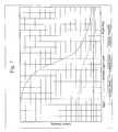
- FIG. 7is a graph of the desired relationship of the detected ambient light level and the threshold level established by the control circuit
- FIG. 8is a simplified side view of the instant invention showing vertical misalignment between the towing unit and the towed unit;
- FIG. 9is a simplified top view of the instant invention showing lateral misalignment between the towing unit and the towed unit;
- FIG. 10is a simplified top view similar to FIG. 8 showing vertical misalignment between the towing unit and the towed unit;
- FIG. 11is a simplified top view similar to FIG. 9 showing lateral misalignment between the towing unit and the towed unit;
- FIG. 12is a block diagram depicting the operation of the coupling alignment warning system
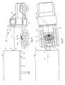
- FIG. 13Ais a side elevational view of a truck including an electronic system for monitoring a trailer hitch assembly according to one embodiment of the present invention
- FIG. 13Bis a bottom plan view of the trailer hitch assembly shown in FIG. 13A;
- FIG. 13Cis a side elevational view of the trailer hitch assembly shown in FIG. 13A;
- FIG. 13Dis a side elevational view in partial cross section of the trailer hitch assembly shown in FIG. 13B;
- FIG. 14is a block diagram of an electronic system for monitoring the trailer hitch assembly shown in FIG. 13A according to one embodiment of the present invention
- FIG. 15is a perspective view of a truck rearview mirror assembly constructed in accordance with a preferred embodiment of the present invention.
- FIG. 16is a close-up partial perspective view of the inventive display incorporated in the rearview mirror assembly shown in FIG. 15 .
- FIG. 1shows the transmitter/receiver components of the coupling alignment warning system (CAWS) 10 for aligning a towing unit with a towed unit by detecting ambient and reflected laser light in the system.
- the transmitterincludes a laser light source 12 (preferably, a laser diode) that is mounted in an adjustable support 14 that is, in turn, attached to the interior of a rugged enclosure 64 .
- rugged enclosure 64is mounted to the towing unit during initial installation as described in more detail below (FIG. 3 ).
- the receiving components of the systemwhich are also shown in FIG. 1, include a spatial filter 18 and a series of sensors 28 , 30 .
- Spatial filter 18has a series of optical tunnels 22 , 26 that limit the amount of light that may reach both ambient sensors 28 and target sensors 30 , that are positioned adjacent thereto, by restricting the angles at which light may impinge upon sensors 28 , 30 .
- Optical tunnels 22(aligned with ambient sensors 28 ) have flared receiving ends 24 so that more ambient light may impinge upon ambient sensors 28 than on target sensors 30 .
- Spatial filter 18also has a tunnel 20 that is aligned with light source 12 so that a collimated light beam 15 emitted from light source 12 is permitted to pass entirely through spatial filter 18 .
- Sensors 28 , 30are mounted in the path of optical tunnels 22 , 26 , respectively, with target sensors 30 being positioned closest to the axis of the collimated light beam 15 emitted by laser light source 12 .
- sensors 28 , 30detect the amount of light in the system including ambient light and, as described in more detail below, laser light that is reflected back towards target sensors 30 to determine whether target acquisition has been achieved. If it has, the CAWS provides continuous feedback to the user indicating that proper coupling will occur as long as alignment is maintained.
- the systemwill not detect reflected laser light and, therefore, will not provide the user with continuous positive coupling feedback, thus indicating to the user that either further maneuvering is necessary to couple the towing unit to the trailer, or that the user should inspect the system for a height adjustment.
- laser light source 12emits collimated light beam 15 that initially passes through a gun-barrel type tunnel 16 between an output end 13 of light source 12 and interior wall 29 of spatial filter 18 .
- Tunnel 16insures that collimated laser light beam 15 passes entirely into tunnel 20 of spatial filter 18 without reaching surrounding sensors 30 , 28 . In other words, tunnel 16 minimizes the chance that the system will detect a false signal.
- target acquisitioni.e., laser light impinges upon the target
- light beam 15is at least partially reflected back toward spatial filter 18 .
- the laser lightis reflected directly back toward laser light source 12 and, therefore, principally impinges upon target sensors 30 (they being closer to the path of the laser light beam).
- the signalsare thereafter processed (described below) and, if a sufficient amount of reflected laser light is detected, the CAWS will indicate that the towed and towing units are aligned for proper coupling. As long as the towing unit remains aligned with the towed unit, the system will indicate that positive coupling will occur without further lateral or height adjustment maneuvering by the user.
- sensors 28 , 30are made from CdSe photo-resistors that have a peak sensitivity in tune with the wavelength of light beam 15 emitted by laser light source 12 ( ⁇ 655 nm).
- spatial filter 18is formed from an opaque, non-reflective medium that has a predetermined thickness; typically, the medium is black hard rubber or plastic that is approximately 0.75 inch thick. Therefore, spatial filter 18 minimizes the reflection of light impinging upon spatial filter 18 and minimizes the chance that other bright sources of light will generate false signals and, therefore, maximizes the chance that the system reliably identifies whether target acquisition has been achieved.
- FIG. 2a block diagram illustrates the operation of the CAWS.
- a control circuit 38calculates a threshold level of light based on the detected level of ambient light. Thereafter, the CAWS determines whether the level of light detected by target sensors 30 reaches that threshold level. If so, control circuit 38 indicates to the user that reflected laser light is being received and that target acquisition has been achieved.
- the CAWSwhen activated, power is supplied to the CAWS, preferably from the battery of the vehicle, through a power converter 48 .
- laser light source 12which is controlled by a microprocessor through a relay, described below
- ambient sensors 28 and target sensors 30detect the amount of ambient light impinging upon sensors 28 and 30 .
- the systemincludes two ambient sensors 28 and two target sensors 30 , each pair being mounted equidistant from tunnel 20 of spatial filter 18 (FIG. 1 ).
- sensors 28 , 30transmit analog output signals, preferably voltage signals, to separate analog-to-digital (A/D) converters 40 , 42 .
- A/D converters 40 , 42The voltage level of the analog output signals varies in response to the sensed level of illumination.
- Each A/D converterhas two inputs for receiving signals from sensors 28 , 30 .
- A/D converters 40 , 42have twelve-bit resolution for converting the analog output signals to discrete values having a high degree of precision.
- the discrete values from the A/D convertersare then transmitted to a microprocessor 46 (preferably including EPROM technology for program control and data storage) which, in turn, calculates a threshold level of reflected laser light that must be detected before the CAWS will signal that target acquisition has been achieved (described in more detail below).
- microprocessor 46activates a relay 44 that allows power to be supplied to laser source 12 .
- Laser source 12preferably a laser diode, then emits collimated laser light beam ( 15 in FIG. 1) that is directed toward a target on the towed unit and reflected back toward laser source 12 when properly aligned.
- sensors 28 , 30detect both ambient light and, upon target acquisition, reflected laser light. As described previously, more ambient light impinges upon ambient sensors 28 due to the corresponding flared ends 24 of optical tunnels 22 , as best shown in FIG. 1 . Further, more of the reflected laser light impinges upon target sensors 30 than ambient sensors 28 because the retro-reflective target returns light back to its source regardless of the angle of impingement (described below) and, thus, target sensors 30 , which are positioned closer to the axis of laser light beam 15 , receive more reflected laser light. Nevertheless, target sensors 30 do detect ambient light, so, as the ambient light levels increase, it becomes more difficult to distinguish the reflected laser light from the detected ambient light.
- the CAWS 10 of the instant inventionsolves this problem by continually updating the threshold level of light based upon the most current level of sensed ambient light.
- microprocessor 46periodically sends a signal to relay 44 which, as a result, deactivates the power supplied to laser source 12 for a predetermined amount of time; preferably, about one half of a second.
- the systemreads all four sensors 28 , 30 simultaneously which, necessarily, are only detecting ambient light.
- These signalsare transmitted to A/D converters 40 , 42 and, thereafter, the digitized signals generated by A/D converters 40 , 42 are transmitted to and processed by microprocessor 46 to establish a new threshold level.
- microprocessor 46activates laser light source 12 , the CAWS reads sensors 28 , 30 and determines whether the digitized signals from target sensors 30 reach this threshold level via a set of instructions programmed into microprocessor 46 .
- Microprocessor 46first processes the digitized target sensor signals and then determines whether the target sensor signal reaches the calculated threshold level and, if so, transmits an indicating signal to an indicator 50 which notifies the user that target acquisition is currently achieved.
- the indicator 50could provide, for example, an LED display and/or an audio output of the indicator signal.
- the LED displaywould remain illuminated as long as the CAWS detects reflected laser light. If the towing and towed units become misaligned, the sensors will no longer detect reflected laser light and the processor will deactivate the LED to signal to the driver that the towing and towed units need to be repositioned for positive coupling to occur.
- FIG. 7A graphical representation of the relationship between the detected ambient light level and the threshold level calculated by microprocessor 46 is shown in FIG. 7 . Because photo-resistor sensors are used, the resistance of sensors 28 , 30 is measured and the resistance levels (ambient, target, and threshold) are plotted as a function of the amount of light detected by the system. As will be appreciated by those skilled in the art, the resistance levels of the sensors may be determined by passing a fixed current through the sensors and monitoring their voltage levels. Also, note that when progressively more light impinges upon the sensors, i.e., when the system is used in the daytime as opposed to night, the resistance of each sensor decreases.
- the “threshold” curvedesignates the resistance level that the target sensors must reach before the CAWS indicates to the user that target acquisition has been achieved.
- the ambient lightconsists mainly of artificial light, such as light emitted by headlights
- the measured resistance of target sensors 30(when target sensors are detecting reflected laser light) is significantly lower than the measured resistance of ambient sensors 28 since ambient sensors 28 receive very little light at all in such conditions.
- the measured resistance of ambient sensors 28decreases dramatically, and approaches the measured resistance of target sensors 30 when target sensors 30 are receiving both reflected laser light and ambient light.
- the CAWScontinually updates the threshold level to establish the greatest degree of distinguishability for varying ambient conditions.
- microprocessor 46By continually updating the threshold resistance level based on the amount of ambient light in the system and by incorporating relatively high resolution A/D converters, microprocessor 46 , which is programmed with instructions to calculate the threshold level based on the desired relationship shown in FIG. 7, determines whether the measured resistance of target sensors 30 reaches the calculated threshold level of resistance. If it does, microprocessor 46 transmits an indicating signal to indicator ( 50 in FIG. 2 ), thus notifying the user that target acquisition is currently achieved. Therefore, the CAWS is reliable regardless of the current amount of ambient light present during operation.
- FIGS. 3 and 4a more detailed description of the initial set-up and operation of the CAWS 10 is shown.
- initial alignment of the system on level groundis shown with the position determining components mounted on a towing unit 60 and a towed unit 62 .
- the CAWS 10includes a rugged enclosure 64 that contains the laser light source 12 , sensors 28 , 30 and the control circuit 38 (not shown in FIGS. 3 and 4 ), as well as a retro-reflective target 70 that together cooperate to send a signal to the driver that continuously indicates alignment of towing unit 60 relative to towed unit 62 as long as laser light impinges upon target 70 .
- FIGS. 3 and 4also show a locking apparatus that is included on the towing and towed units 60 , 62 .
- towed unit 62has what is commonly known in the commercial trucking industry as a king pin 74 that extends downwardly from a bottom surface 76 of towed unit 62 .
- towing unit 60has what is known in the trucking industry as a fifth wheel hitch 78 .
- Fifth wheel hitch 78includes a hitch plate 80 having a throat 82 (FIG. 4) for receiving king pin 74 and which pitches about a mounting bracket 83 approximately at its center.
- Fifth wheel hitch 78is mounted to a frame 79 of towing unit 60 (FIG. 4) such that an open end 86 of throat 82 faces rearwardly to receive and lock king pin 74 of towed unit 62 when the two are brought into engagement.
- rugged enclosure 64is mounted to a back wall 66 of towing unit 60 , above the grease and contaminant area, so that light beam 15 emitted by laser light source 12 is directed generally perpendicular to wall 66 of towing unit 60 . Further, rugged enclosure 64 is mounted at a height X defined by a top surface 84 of hitch plate 80 when hitch plate 80 is level and the axis of light beam 15 emitted from laser source 12 , laser source 12 being mounted in rugged enclosure 64 as best shown in FIG. 3 . Retro-reflective target 70 is mounted to a front vertical surface 68 of towed unit 62 at a height corresponding to the height X at which rugged enclosure 64 is installed.
- retro-reflective target 70is attached to surface 68 at distance X defined by a bottom surface 76 of towed unit 62 (which is at the same height relative to the ground as top surface 84 of hitch plate 80 when coupled) and a bottom surface 72 of retro-reflective target 70 , such that laser light beam 15 contacts bottom surface 72 of retro-reflective target 70 when towed unit 62 and towing unit 60 are on level ground, as shown in FIG. 3 .
- Light beam 15is initially aligned so it strikes lower edge 72 and center of target 70 to accommodate the tolerance of allowed vertical misalignment (described below). Further, turning to FIG. 4, rugged enclosure 64 is mounted such that laser beam 15 is emitted perpendicularly from, in the preferred embodiment, the center of width of back wall 66 of towing unit 60 , corresponding to the center axis of throat 82 of fifth wheel hitch 78 . Retro-reflective target 70 is placed at the center of width of surface 68 of towed unit 62 , which corresponds to the position of king pin 74 , i.e., king pin 74 is likewise centered relative to the width of towed unit 62 .
- the enclosure 64 and target 70could be offset to accommodate alternate mounting on some trailers.
- retro-reflective target 70is, in the preferred embodiment, removably attached to towed unit 62 for ready installation and adaptability.
- target 70may have a magnetic backing that makes attaching and aligning the CAWS at initial installation relatively effortless.
- towed unit 62could first be coupled to towing unit 60 and, thereafter, the user could adjust the position of retro-reflective target 70 with respect to rugged enclosure 64 to achieve the alignment shown in FIGS. 3 and 4. The user would activate the CAWS and position enclosure 64 and target 70 so that the axis of light beam 15 is directed at the center of bottom surface 72 of target 70 when towing unit 60 and towed unit 62 are on level ground.
- retro-reflective target 70The specific characteristics of retro-reflective target 70 are preferably exploited during the operation of the CAWS 10 .
- the nature of retro-reflective target 70is such that, when laser light from laser source 12 impinges upon it, the target returns the laser light directly to source 12 regardless of impingement angle.
- Target 70has an array of closely spaced miniature corner cube reflectors, each of which contains three walls that are mutually perpendicular for reflecting light back to its source. Also, to insure that all the light that impinges on the cube reflector returns to the laser light source 12 , the surface of each cube reflector is made of a highly reflective material.
- retro-reflective target 70corrects for off-angle coupling approaches within a range of ⁇ 45°.
- Commercially available retro-reflective targetswhich offer acceptable performance, include Model BRT-2 ⁇ 2 by Banner Engineering Corp. and Model UZZ112 from Nais Aromat Corp.
- the lateral misalignment toleranceis defined by the dimensions of fifth wheel hitch 78 and, more particularly, the dimensions of open end 86 of throat 82 of fifth wheel hitch 78 .
- the vertical misalignment toleranceis defined by the maximum height that the ramps (not shown) on the open end 86 of throat 82 can safely engage the lower front edge 87 of towed unit 62 and “lift” said towed unit to the proper height during the coupling action (FIG. 3 ). As best shown in FIGS.
- retro-reflective target 70is rectangular having dimensions that are approximately four inches high by twelve inches wide corresponding to the dimensions of the opening of throat 82 of fifth-wheel hitch 78 and king pin 74 .
- the CAWSsenses target acquisition and, as the driver backs up towing unit 60 , bottom surface 76 of towed unit 62 will contact the top surface 84 of hitch plate 80 and king pin 74 will enter throat 82 to couple fifth wheel hitch 78 and king pin 74 . If the height of towed unit 62 is lower than that shown in FIG.
- the CAWS 10will continue to indicate proper alignment as long as the height of towed unit 62 is not more than four inches below the initial, and ideal, height that is shown in FIG. 5 . If towed unit 62 is more than four inches below the height shown in FIG. 5, surface 68 of towed unit 62 may crash into outwardly facing open end 86 of hitch plate 80 .
- the instant inventionaccounts for this potential fault condition by utilizing a retro-reflective target that is four inches high. If towed unit 62 and, necessarily, retro-reflective target 70 attached thereto is lower than four inches below what it is in initial alignment, laser light beam 15 will not impinge upon retro-reflective target 70 and no laser light will be reflected back toward rugged enclosure 64 . Thus, the CAWS 10 will not detect reflected laser light and will indicate to the user that target acquisition has not been achieved, i.e., that positive coupling will not occur without repositioning the towing and/or towed units.
- king pin 74will be too high to engage throat 82 of fifth wheel hitch 78 and positive coupling cannot occur (FIG. 10 ). In this case, as shown in FIGS. 8 and 10 , no laser light will contact retro-reflective target 70 and the system will appropriately indicate that target acquisition has not been achieved.
- the CAWS 10will tolerate a twelve-inch range of lateral misalignment. Because laser source 12 mounted in rugged enclosure 64 is initially aligned so that laser light beam 15 strikes the center of retro-reflective target 70 and because retro-reflective target 70 is twelve inches wide, the system will signal to the user that towing unit 60 will be unable to couple to towed unit 62 if the approach that the driver of towing unit 60 takes is more than six inches, in either lateral direction, off the center line of initial alignment (shown in FIG. 4 ). As depicted in FIGS.
- FIG. 12shows that, in the preferred embodiment, when the system 100 is activated (step 101 ), the analog-to-digital converters are initialized (step 102 ) while the laser light source is off (step 104 ). Then, the microprocessor clock signal is started (step 106 ) and the sensors, ambient and target, are read (step 108 ), digitized and electrically coupled to the processor for computation of the threshold level (step 110 ) based on the amount of ambient light in the system (described above). Next, the laser light source is activated (step 112 ) and the sensors are continuously read (step 114 ) as the driver attempts to couple the towing unit with the towed unit.
- the sensor signalsare digitized by the analog-to-digital converters, and then coupled to the processor which computes a value, S_MIN (step 116 ), that is compared with the computed threshold level (step 118 ).
- S_MINa value that is compared with the computed threshold level
- a positive coupling signalstep 120
- the processorasks whether the clock signal is greater than two seconds (step 122 ), and, if so, computes a new threshold level based on the then current amount of ambient light in the system.
- the laser light sourcecould be mounted on the towing unit so that it is capable of multi-dimension tracking of the position of the towed unit by, for example, mounting laser light source 12 on a gimbal system.
- the lasercould maintain target acquisition even when the relative height between the towed and towing units varies, e.g., when backing up on a hill.
- the systemcould be adapted for scanning the retro-reflective target laterally and/or vertically, therefore tracking the position of the towing unit relative to the towed unit in two dimensions. The measured azimuth and elevation angles could be transmitted to the user via the display unit to further assist in maneuvering the towing unit for proper alignment with the towed unit.
- the detected light signalscould be processed by a wave band filter tuned to pass only light having a wavelength corresponding to the emitted laser light. If the filter passes a signal, the system necessarily must be detecting reflected laser light and, therefore, will indicate to the user that target acquisition has been achieved.
- the systemcan indicate to the user whether reflected laser light has been sensed and, therefore, whether target acquisition has been achieved.
- the CAWSmay be manually activated by the user or, alternatively, the system may be activated by certain vehicle operations. For instance, the system could be adapted to sense when the towing unit is in reverse and, in response, activate the CAWS. To deactivate the CAWS, the system could be used in conjunction with the fifth wheel hitch coupling control systems disclosed in U.S. patent application Ser. No. 09/493,534 or U.S. Pat. No.
- 5,861,802which both include an optional tilt sensor for sensing when the fifth wheel hitch plate is tilted from its resting position indicating that the trailer is now proximate the fifth wheel, a king pin sensor for sensing when the king pin has entered the throat of the fifth wheel hitch, and a lock sensor for detecting when a locking mechanism of a trailer hitch assembly is locked.
- an optional tilt sensorfor sensing when the fifth wheel hitch plate is tilted from its resting position indicating that the trailer is now proximate the fifth wheel
- a king pin sensorfor sensing when the king pin has entered the throat of the fifth wheel hitch
- a lock sensorfor detecting when a locking mechanism of a trailer hitch assembly is locked.
- activation/deactivation of the CAWSmay be automatically controlled; for example, when the lock sensor detects that the fifth wheel hitch is locked to the king pin, the lock sensor signal could be utilized to deactivate the CAWS.
- the CAWSmay be automatically activated when the truck is placed in reverse, and when interfaced with the coupling control systems discussed above, activation may be prohibited when the coupling control system has detected that the trailer has already fully hitched and locked to the fifth wheel hitch.
- FIG. 13Ashows a truck tractor 310 which includes a trailer hitch assembly 320 having a base 324 securely mounted to a chassis 380 , a trailer hitch plate 326 pivotally mounted on base 324 on a transverse axis and a locking mechanism 328 for locking a conventional trailer kingpin in place.
- the electronic system of the present inventionpreferably includes three proximity sensors mounted to hitch assembly 320 and an output device 350 mounted in the cab of tractor 310 . These sensors are coupled to output device 350 by a multi-conductor cable 345 .
- the three sensors mounted to trailer hitch assembly 320include a tilt sensor 332 , a kingpin sensor 334 and a lock sensor 336 . Depending upon the application, tilt sensor 332 may not be implemented.
- FIGS. 13B-13Dprovide a more detailed view of trailer hitch assembly 320 of FIG. 13 A.
- tilt sensor 332is mounted on a flange 323 of hitch plate 326 such that the sensing end faces outward in a direction perpendicular to the pivot pins 321 .
- FIG. 13Cshows the hitch plate 326 from the side in combination with base 324 in a coupled horizontal position 325 and in an uncoupled at rest position 327 (dashed lines).
- tilt sensor 332By mounting a metal plate 385 on chassis 380 in a position near where the sensing end of tilt sensor 332 is positioned when trailer hitch plate 326 is in the resting position, tilt sensor 332 detects the presence of plate 385 as a basis for determining that the hitch plate is tilted or at a rest position.
- tilt sensor 332detects the presence of plate 385 as a basis for determining that the hitch plate is tilted or at a rest position.
- tractor 310is backed under a trailer, contact is made between a tilted hitch plate 326 and a portion of the trailer. This contact causes hitch plate 326 to rotate into a coupled (horizontal) position.
- tilt sensor 332subsequently detects the absence of plate 385 , it can be concluded that hitch plate 326 has been moved from its rest position and the trailer is in proximity to the hitch assembly.
- sensor 332may be mounted so as to detect metal when hitch plate 326 is in the horizontal coupled position.
- FIG. 13Bshows kingpin sensor 334 mounted to hitch plate 326 with the sensing end near the throat 60 formed in hitch plate 326 , into which a trailer kingpin 370 is positioned and locked.
- FIG. 13Dprovides an upside-down side view and partial cross-section illustrating the location of trailer kingpin 370 when properly disposed in throat 360 .
- kingpin sensor 334outputs a detection signal when the metal trailer kingpin's lower flange is disposed in throat 360 , below a lock plane 361 . That is, kingpin sensor 334 is in a plane below locking mechanism 328 and only detects kingpin 370 when a kingpin rib 362 of kingpin 370 extends below lock plane 361 .
- kingpin sensor 334prevents it from indicating that kingpin 370 is present when a high coupling occurs, which prevents locking mechanism 328 from securing kingpin 370 (i.e., the trailer) to hitch plate assembly 320 .
- Locking mechanism 328of hitch plate assembly 320 , is biased by a compression spring to automatically lock-in and secure the trailer kingpin 370 , as soon as it enters the hitch throat 360 .
- FIG. 13Bshows lock sensor 336 mounted to hitch plate 326 such that a sensing end is in a position proximate to a position of that of a metal cam plate 329 (of locking mechanism 328 ) when in a locked position.
- lock sensor 336detects the presence of cam plate 329 as a basis for detecting if the locking mechanism is in a locked and secured position.
- lock sensor 336may be used in connection with any type of a locking mechanism. It should also be noted that the present invention may be applied to trailer hitch assemblies having other constructions and is not limited to particular mounting locations shown for sensors 332 , 334 and 336 .
- FIG. 14depicts a block diagram of an electronic system 400 , according to an embodiment of the present invention.
- Electronic system 400includes a processor 402 that receives input from sensors 332 , 334 and 336 .
- Processor 402is also coupled to a memory 404 and an output device such as an alpha-numeric display 228 of a display 220 , as described below.
- processor 402is a PIC16C62, manufactured by Microchip Technology Inc. of Chandler, Ariz.
- a plurality of outputs of processor 402are coupled through current limiting resistors 422 , 424 , 426 , 428 and 430 to LEDs 412 , 414 , 416 , 418 and 420 , respectively.
- Processor 402runs a routine that, depending upon the input from sensors 332 , 334 and 336 , may cause an error code to appear on alpha-numeric display 228 and may cause different ones or combinations of LEDs 412 - 420 to be illuminated thereby illuminating one or more of display icons 222 - 226 and indicator light 230 of display 220 , as described below.
- a positive voltageis applied at terminal 401 that enables LEDs 412 - 420 to emit light, as dictated by processor 402 .
- the coupling control systems discussed abovefurther include a display for displaying coupling status information to the driver.
- a displayallows the driver to monitor the status of the hitch coupling to confirm that the hitch locking mechanism is properly locked about the king pin without requiring the driver to leave his or her cab and manually inspect the hitch.
- the systemmay also provide a visible and/or audible warning when it is determined that the hitch is not properly locked about the king pin.
- both the displays for the coupling control systems discussed above and the CAWSmay be integrated into a single display.
- a preferred implementation of the displayis to position the display on or within the truck's driver side rearview mirror assembly.
- the rearview mirror assemblyis a preferred location for this display since the truck driver is typically utilizing this mirror while backing up to a trailer and while coupling to the trailer. Thus, a driver would not need to divert his or her eyes from the mirror to view the display.
- a preferred implementation of the display in a rearview mirror assemblyis described below with reference to FIGS. 15 and 16.
- a truck rearview mirror assembly 200may include a housing 201 in which a first mirror 202 is mounted.
- a second lower mirror portion 204may optionally be mounted in housing 201 , as is conventional in the art, so as to allow the driver to view scenes from a different angle and thereby reduce the driver's blind spots.
- Mirrors 202 and 204may be movably mounted within housing 201 or, optionally, housing 201 may be movably mounted to one or more mounting brackets 206 , which are adapted to mount the mirror assembly to the exterior of the truck cab in a conventional manner.
- At least one of mounting supports 206defines a conduit through which a wire harness 208 may be run to provide electrical power and communication to any electrical components disposed within rearview mirror assembly 200 .
- electrical componentsmay include the inventive display 220 and also may include a motor for moving one or both of mirror portions 202 and 204 , a heater disposed behind the mirror for heating the mirror and melting ice and snow from its surface during the winter, and any turn signal indicator or other lights disposed on mirror housing 201 .
- antennasare sometimes mounted to truck mirrors such that wire harness 208 may include an antenna lead line.
- display 220may be positioned behind one of mirror surfaces 202 or 204 .
- the transparent window 210is preferably formed in the reflective coating of one of mirror portions 202 or 204 .
- the reflective coating on the mirrormay be both partially reflective and partially transmissive to allow light from the display to be transmitted through the partially reflective and partially transmissive coating on the mirror.
- display 220could be positioned on the housing 201 adjacent one of mirrors 202 and 204 or on one of the mirror bezels.
- Display 220may be of any form and display the requisite information in any format.
- FIG. 16shows a preferred display 220 .
- display 220is intended to display trailer coupling status information to the driver of the truck. Such information may include whether the truck hitch is in a ready-to-couple condition, whether the truck and its hitch are aligned with the trailer and its king pin, whether proper coupling has occurred, whether improper coupling has occurred, an error code identifying a potential reason why an improper coupling has occurred, and/or other information pertaining to the hitch such as the position of a sliding fifth wheel hitch and readings from a force sensing fifth wheel hitch such as that disclosed in commonly assigned U.S.
- display 220includes a fifth wheel-shaped icon 222 , an open or unlocked padlock icon 224 , a closed or locked padlock icon 226 , and a seven-segment alphanumeric display 228 .
- Alphanumeric display 228may be used to display an error code, such as a number 0 through 9, which would enable the driver to refer to a reference book to determine the potential reason why a coupling attempt failed.
- display 220may further include an indicator light 230 , which is a bright light directed towards the eyes of the driver.
- Indicator 230is provided for the express purpose of attracting the driver's attention to the display when, for example, a properly coupled hitch suddenly becomes unhitched when the coupling system specifically determines that the uncoupling was a result of a failure or improper uncoupling attempt.
- Display 220may further include an indicator 50 corresponding to the indicator of the CAWS for indicating when the trailer is in alignment with the truck.
- Indicators 50 and 230are shown as simply being circles. However, specific icons may be developed to aid in distinguishing one from another and from distinguishing the indicators from the other icons of the display.
- indicator 50could be represented as a target icon or the like to indicate alignment of the truck and trailer.
- display 220includes a display panel having a black surface with masked or etched-out transparent portions in the shape of the icons, alphanumeric display window, or indicators. LEDs are then placed behind the icons and indicator windows to selectively illuminate the icons and indicators.
- a red LEDis provided behind the “unlocked” icon 224 ; either a yellow, red, and green tri-color LED or a bi-color LED is provided behind the “fifth wheel” icon 222 ; and a green LED is provided behind the “lock” icon 55 .
- the individual LEDscould be replaced with an LED array capable of providing multiple colors.
- the LEDs provided behind the openings for indicators 50 and 230may be any suitable color.
- Alphanumeric display 228may have any form, and is preferably a seven-segment LED display. Although an alphanumeric display 228 is shown that displays only a single alphanumeric character at a time, display 228 may be configured to display many characters at once and could be used to display messages in lieu of the icons that are otherwise provided.
- the iconsmay be illuminated as follows.
- the CAWSmay be activated at which point indicator 50 is illuminated, provided the truck is in alignment with the trailer.
- fifth wheel icon 222may be illuminated with the yellow light from the tri-color LED to indicate that the fifth wheel is in a ready-to-couple condition.
- icon 222may be green to indicate a ready-to-couple condition.
- icon 222may change from a yellow to green color. This may otherwise occur when the king pin is sensed in the throat of the fifth wheel hitch plate. Then, when the lock sensor senses that the locking mechanism has properly locked the king pin in place, the “locked” icon 226 is illuminated with its green LED along with a green fifth wheel icon 222 to indicate to the driver that proper coupling has occurred. At any of these stages during the coupling process, indicator 50 for the CAWS may be turned off to avoid further distraction.
- fifth wheel icon 222may be illuminated with red light while “unlocked” icon 224 may also be illuminated with red light to clearly display to the driver that improper coupling has occurred.
- Indicator 230may be activated at this time to ensure the driver is watching the display 220 .
- An error codemay then be displayed on alpha-numeric display 228 to indicate a potential reason for the failed coupling attempt.
- a fifth wheel hitch coupling control systemwhich senses these conditions and analyzes the sequence and timing of the hitching events to control a similar display, is disclosed in U.S. patent application Ser. No. 09/1493,534, the entire disclosure of which is incorporated herein by reference.
- the circuitry for driving display 220is provided in rearview mirror housing 201 .
- the display drivermay be coupled via wiring harness 208 to the associated processing circuits for the CAWS and/or the fifth wheel coupling control system. It is also possible to combine the processing circuits for the CAWS and fifth wheel coupling control systems. In this arrangement, the processing circuit(s) would be mounted within the truck remote from rearview mirror assembly 200 . It is also possible that such circuitry could be mounted within rearview mirror assembly housing 201 with appropriate couplings to the system sensors and to the laser of the CAWS via wiring harness 208 . Alternatively, some of the processing may be split such that preprocessing of the signals from the sensors may be performed remote from rearview mirror assembly 200 while some of the decision, post-processing, and display control may be performed by a processor located in mirror housing 201 .
- Display 220should provide sufficient brightness to allow the driver to view the display during bright conditions, but should not be so bright as to overwhelm the driver during nighttime conditions.
- display 220 and any other circuitry for the associated systemsare provided on a circuit board that is potted within the mirror housing so as to protect the circuit and display from vibration, extreme temperatures, and moisture. It may also be desirable to shield the circuitry with an electrically conductive subhousing so as to not cause interference with any CB radio antenna or other radio antenna that is mounted to the mirror assembly. If the rearview mirror assembly incorporates a mirror heater, it may be desirable to modify the heating lines of the heater to extend around the display area. Preferably, the heater would at least heat the periphery of the display area to ensure that the display is cleared of ice and snow.
- any additional information from any other systems or any additional information from the above-described systemsmay be displayed on display 220 .
- the estimated distance to the trailermay be displayed on an alpha-numeric display or otherwise indicated by a series of LED devices or LED segments to represent the proximity of the truck to the trailer.
- an indication of how close the truck is to being in alignment with the trailermay also be provided. Such an indication may show in which direction the truck is out of alignment (i.e., to the left, to the right, too high, or too low).
- the entire systemmay draw its operating power from the truck's power supply, typically a twelve-volt battery.
- the indicatoris preferably mounted to the exterior mirror of the truck, it may also be mounted within the cab or any convenient place in which it may be monitored by the operator of the vehicle.
- the CAWScould be used in conjunction with the coupling control system of the above-referenced '534 application to record additional feedback information as the driver attempts to achieve positive coupling.
- the proximity sensing capabilities of the '534 applicationcould be utilized to signal the microprocessor 46 to begin recording position data within a predetermined range, preferably near coupling. By analyzing the recorded data, users will be able to determine whether the driver maneuvered the towing unit in response to a CAWS signal that indicated that the towing unit was aligned with the towed unit.
- the present inventioncould be used to align the back of a trailer with a loading dock, and the CAWS could be used in various other transportation alignment applications.
- the retro-reflective targetcould be mounted in a boat docking station, with the primary system components mounted on the boat, for assisting the driver with parking the boat.
Landscapes
- Engineering & Computer Science (AREA)
- Chemical & Material Sciences (AREA)
- Combustion & Propulsion (AREA)
- Transportation (AREA)
- Mechanical Engineering (AREA)
- Optical Radar Systems And Details Thereof (AREA)
- Length Measuring Devices By Optical Means (AREA)
Abstract
Description
Claims (20)
Priority Applications (1)
| Application Number | Priority Date | Filing Date | Title |
|---|---|---|---|
| US09/836,796US6592230B2 (en) | 1997-10-16 | 2001-04-17 | Truck rearview mirror assembly having a display for displaying trailer coupling status information |
Applications Claiming Priority (3)
| Application Number | Priority Date | Filing Date | Title |
|---|---|---|---|
| US08/951,250US6252497B1 (en) | 1997-10-16 | 1997-10-16 | Coupling alignment warning system |
| US09/493,534US6285278B1 (en) | 2000-01-28 | 2000-01-28 | Electronic system for monitoring a fifth wheel hitch |
| US09/836,796US6592230B2 (en) | 1997-10-16 | 2001-04-17 | Truck rearview mirror assembly having a display for displaying trailer coupling status information |
Related Parent Applications (2)
| Application Number | Title | Priority Date | Filing Date |
|---|---|---|---|
| US08/951,250Continuation-In-PartUS6252497B1 (en) | 1997-10-16 | 1997-10-16 | Coupling alignment warning system |
| US09/493,534Continuation-In-PartUS6285278B1 (en) | 1997-10-16 | 2000-01-28 | Electronic system for monitoring a fifth wheel hitch |
Publications (2)
| Publication Number | Publication Date |
|---|---|
| US20010022731A1 US20010022731A1 (en) | 2001-09-20 |
| US6592230B2true US6592230B2 (en) | 2003-07-15 |
Family
ID=27051111
Family Applications (1)
| Application Number | Title | Priority Date | Filing Date |
|---|---|---|---|
| US09/836,796Expired - Fee RelatedUS6592230B2 (en) | 1997-10-16 | 2001-04-17 | Truck rearview mirror assembly having a display for displaying trailer coupling status information |
Country Status (1)
| Country | Link |
|---|---|
| US (1) | US6592230B2 (en) |
Cited By (63)
| Publication number | Priority date | Publication date | Assignee | Title |
|---|---|---|---|---|
| US20040032321A1 (en)* | 2002-04-19 | 2004-02-19 | Mcmahon Martha A. | Vehicle imaging system |
| US20050062590A1 (en)* | 2003-09-05 | 2005-03-24 | Heinrich Lang | Wireless data transfer system for a tractor-trailer |
| US20050131603A1 (en)* | 2003-12-05 | 2005-06-16 | Hongwei Liu | Vehicle safety system having methods and apparatus configurable for various vehicle geometries |
| US20050151631A1 (en)* | 2003-11-24 | 2005-07-14 | Honan James W.Iii | Radar hitch |
| US20050213231A1 (en)* | 2004-03-29 | 2005-09-29 | Harrison Charles E Iii | Backing mirror |
| US20060064208A1 (en)* | 2004-09-22 | 2006-03-23 | Heinrich Lang | System for transmitting signals in a motor vehicle |
| US20060225293A1 (en)* | 2005-04-11 | 2006-10-12 | Godwin W L | Trailer hitch alignment device |
| US20060290100A1 (en)* | 2005-06-23 | 2006-12-28 | Steve Miller | Vehicle hitch aligning system |
| US20060290099A1 (en)* | 2003-09-03 | 2006-12-28 | Siegfried Buttner | Fifth wheel with anti-theft protection device |
| US20070075522A1 (en)* | 2005-09-30 | 2007-04-05 | Hermon Christopher J | Recreational vehicle |
| US20080036173A1 (en)* | 2004-09-18 | 2008-02-14 | Jost-Werke Gmbh & Co.Kg | Adjusting Device, Air Deflecting System, Control Member and Device Enabling Aerodynamic Resistance of a Semi-Trailer to be Reduced |
| US20080180526A1 (en)* | 2007-01-25 | 2008-07-31 | Trevino James S | Towing vehicle guidance for trailer hitch connection |
| US20080217883A1 (en)* | 2005-11-07 | 2008-09-11 | Volvo Lastvagnar Ab | Tractor Adapted to Be Connected to a Semi-Trailer |
| US20080258896A1 (en)* | 2007-04-17 | 2008-10-23 | Stoller Jason J | System for improving back end visibility and machine using same |
| US7815326B2 (en) | 2002-06-06 | 2010-10-19 | Donnelly Corporation | Interior rearview mirror system |
| US7821697B2 (en) | 1994-05-05 | 2010-10-26 | Donnelly Corporation | Exterior reflective mirror element for a vehicular rearview mirror assembly |
| US7822543B2 (en) | 2000-03-02 | 2010-10-26 | Donnelly Corporation | Video display system for vehicle |
| US7826123B2 (en) | 2002-09-20 | 2010-11-02 | Donnelly Corporation | Vehicular interior electrochromic rearview mirror assembly |
| US7832882B2 (en) | 2002-06-06 | 2010-11-16 | Donnelly Corporation | Information mirror system |
| US7855755B2 (en) | 2005-11-01 | 2010-12-21 | Donnelly Corporation | Interior rearview mirror assembly with display |
| US7859737B2 (en) | 2002-09-20 | 2010-12-28 | Donnelly Corporation | Interior rearview mirror system for a vehicle |
| US7864399B2 (en) | 2002-09-20 | 2011-01-04 | Donnelly Corporation | Reflective mirror assembly |
| US7888629B2 (en) | 1998-01-07 | 2011-02-15 | Donnelly Corporation | Vehicular accessory mounting system with a forwardly-viewing camera |
| US7898398B2 (en) | 1997-08-25 | 2011-03-01 | Donnelly Corporation | Interior mirror system |
| US7898719B2 (en) | 2003-10-02 | 2011-03-01 | Donnelly Corporation | Rearview mirror assembly for vehicle |
| US7906756B2 (en) | 2002-05-03 | 2011-03-15 | Donnelly Corporation | Vehicle rearview mirror system |
| US7914188B2 (en) | 1997-08-25 | 2011-03-29 | Donnelly Corporation | Interior rearview mirror system for a vehicle |
| US7916009B2 (en) | 1998-01-07 | 2011-03-29 | Donnelly Corporation | Accessory mounting system suitable for use in a vehicle |
| US7926960B2 (en) | 1999-11-24 | 2011-04-19 | Donnelly Corporation | Interior rearview mirror system for vehicle |
| US20110216199A1 (en)* | 2007-01-25 | 2011-09-08 | Target Hitach LLC | Towing vehicle guidance for trailer hitch connection |
| US8019505B2 (en) | 2003-10-14 | 2011-09-13 | Donnelly Corporation | Vehicle information display |
| US8044776B2 (en) | 2000-03-02 | 2011-10-25 | Donnelly Corporation | Rear vision system for vehicle |
| US8049640B2 (en) | 2003-05-19 | 2011-11-01 | Donnelly Corporation | Mirror assembly for vehicle |
| US8072318B2 (en) | 2001-01-23 | 2011-12-06 | Donnelly Corporation | Video mirror system for vehicle |
| US8083386B2 (en) | 2001-01-23 | 2011-12-27 | Donnelly Corporation | Interior rearview mirror assembly with display device |
| US8154418B2 (en) | 2008-03-31 | 2012-04-10 | Magna Mirrors Of America, Inc. | Interior rearview mirror system |
| US20120098243A1 (en)* | 2009-07-07 | 2012-04-26 | Marcos Angel Diaz | Trailer having secondary wheel attached to adjustable leg |
| US8194133B2 (en) | 2000-03-02 | 2012-06-05 | Donnelly Corporation | Vehicular video mirror system |
| US8288711B2 (en) | 1998-01-07 | 2012-10-16 | Donnelly Corporation | Interior rearview mirror system with forwardly-viewing camera and a control |
| US8294975B2 (en) | 1997-08-25 | 2012-10-23 | Donnelly Corporation | Automotive rearview mirror assembly |
| US8462204B2 (en) | 1995-05-22 | 2013-06-11 | Donnelly Corporation | Vehicular vision system |
| US8503062B2 (en) | 2005-05-16 | 2013-08-06 | Donnelly Corporation | Rearview mirror element assembly for vehicle |
| US8511841B2 (en) | 1994-05-05 | 2013-08-20 | Donnelly Corporation | Vehicular blind spot indicator mirror |
| US8525703B2 (en) | 1998-04-08 | 2013-09-03 | Donnelly Corporation | Interior rearview mirror system |
| US9019091B2 (en) | 1999-11-24 | 2015-04-28 | Donnelly Corporation | Interior rearview mirror system |
| US20150198949A1 (en)* | 2014-01-14 | 2015-07-16 | Zf Lenksysteme Gmbh | Method for controlling the driving of a big rig and drive control system |
| US20160339836A1 (en)* | 2015-05-20 | 2016-11-24 | Saf-Holland, Inc. | Fifth Wheel Coupling Detection System with Inspection and Indication Lighting Arrangement |
| US20180146304A1 (en)* | 2015-04-13 | 2018-05-24 | DSCG Solutions, Inc. | Audio detection system and methods |
| US10195912B2 (en) | 2014-10-23 | 2019-02-05 | Carrier Corporation | Coupling assist system for a tractor trailer |
| USD882426S1 (en) | 2018-09-17 | 2020-04-28 | Waymo Llc | Integrated sensor assembly |
| US10670479B2 (en) | 2018-02-27 | 2020-06-02 | Methode Electronics, Inc. | Towing systems and methods using magnetic field sensing |
| US10696109B2 (en) | 2017-03-22 | 2020-06-30 | Methode Electronics Malta Ltd. | Magnetolastic based sensor assembly |
| US20210125433A1 (en)* | 2019-10-23 | 2021-04-29 | Brandon Gonzalez | Safety system for coupling truck and trailer |
| US11014416B2 (en) | 2015-12-11 | 2021-05-25 | Eaton Intelligent Power Limited | Autonomous dock |
| US11014417B2 (en) | 2018-02-27 | 2021-05-25 | Methode Electronics, Inc. | Towing systems and methods using magnetic field sensing |
| US11084342B2 (en) | 2018-02-27 | 2021-08-10 | Methode Electronics, Inc. | Towing systems and methods using magnetic field sensing |
| US11135882B2 (en) | 2018-02-27 | 2021-10-05 | Methode Electronics, Inc. | Towing systems and methods using magnetic field sensing |
| US11142442B2 (en) | 2017-02-10 | 2021-10-12 | Arrow Acquisition, Llc | System and method for dynamically controlling the stability of an industrial vehicle |
| US11221262B2 (en) | 2018-02-27 | 2022-01-11 | Methode Electronics, Inc. | Towing systems and methods using magnetic field sensing |
| US11491832B2 (en) | 2018-02-27 | 2022-11-08 | Methode Electronics, Inc. | Towing systems and methods using magnetic field sensing |
| US11718230B2 (en) | 2019-04-16 | 2023-08-08 | Muth Mirror Systems, Llc | Mirror assembly for autonomous maneuvers |
| US11899466B2 (en) | 2017-12-29 | 2024-02-13 | Waymo Llc | Sensor integration for large autonomous vehicles |
| US20240227956A9 (en)* | 2022-09-13 | 2024-07-11 | Jost-Werke Deutschland Gmbh | Method for coupling a tractor with a semi-trailer and a semi-truck with a tractor and a semi-trailer |
Families Citing this family (13)
| Publication number | Priority date | Publication date | Assignee | Title |
|---|---|---|---|---|
| DE10341622B3 (en)* | 2003-09-10 | 2005-08-18 | Preh Gmbh | Display device with combined light guide |
| US8497761B2 (en) | 2005-01-13 | 2013-07-30 | Rite-Hite Holding Corporation | System and method for remotely controlling docking station components |
| DE102005014977B4 (en)* | 2005-03-24 | 2008-08-21 | Jost-Werke Gmbh | Device for detecting and displaying the position of components of vehicle clutches |
| US8528929B2 (en)* | 2010-01-21 | 2013-09-10 | Midwest Industrial Door, Inc. | Trailer docking repositionable support |
| MX2012013357A (en) | 2010-05-19 | 2013-04-22 | Midwest Ind Door Inc | Trailer stabilizer. |
| US8643481B2 (en)* | 2010-09-17 | 2014-02-04 | Johnson Controls Technology Company | Interior rearview mirror assembly with integrated indicator symbol |
| DE102013101017A1 (en)* | 2013-02-01 | 2014-08-07 | Sven Dörnbach | fifth wheel |
| US9656637B2 (en) | 2014-07-01 | 2017-05-23 | Stabilock, LLC | Trailer stabilization and restraint |
| US11618376B2 (en) | 2014-10-30 | 2023-04-04 | Crc R&D, Llc | Methods, apparatuses, and systems for monitoring state of a transportation system |
| US9914392B2 (en) | 2014-10-30 | 2018-03-13 | Cross Road Centers, Llc | Methods, apparatuses, and systems for monitoring state of a transportation system |
| MX387075B (en)* | 2015-08-19 | 2025-03-19 | Stabilock Llc | STABILIZER AND TRAILER RESTRAINT. |
| IT201600093812A1 (en)* | 2016-09-19 | 2018-03-19 | Iveco Spa | INTERCONNECTION SYSTEM BETWEEN A TRACTOR AND A TRAILER |
| KR20190101909A (en)* | 2018-02-23 | 2019-09-02 | 주식회사 비트센싱 | Viechle radar system for sensing danger |
Citations (82)
| Publication number | Priority date | Publication date | Assignee | Title |
|---|---|---|---|---|
| US809698A (en) | 1905-04-07 | 1906-01-09 | Howard S Jones | Display-mirror. |
| US1528082A (en) | 1919-08-25 | 1925-03-03 | Harrison H Boyce | Mirrorscope thermometer |
| US1849708A (en) | 1930-12-19 | 1932-03-15 | Liberty Mirror Works | Rear view mirror |
| US1884759A (en) | 1930-08-30 | 1932-10-25 | Standard Mirror Co Inc | Combined mirror and instrument |
| US1908767A (en) | 1931-11-13 | 1933-05-16 | Standard Mirror Co Inc | Combined mirror and instrument |
| US2166303A (en) | 1937-06-03 | 1939-07-18 | Standard Mirror Company | Mirror |
| US2561582A (en) | 1949-06-11 | 1951-07-24 | Meyer M Marbel | Directional mirror for motor vehicles |
| US2982566A (en) | 1959-04-27 | 1961-05-02 | Holland Hitch Co | Fifth wheel |
| US3013815A (en) | 1959-04-27 | 1961-12-19 | Holland Hitch Co | Fifth wheel construction |
| US3535679A (en) | 1967-10-05 | 1970-10-20 | John S Connors | Safety signal mechanism for a tractor semi-trailer fifth wheel connector |
| US3640549A (en) | 1970-03-02 | 1972-02-08 | Holland Hitch Co | Nonsquirt fifth wheel assembly |
| US3697974A (en) | 1970-10-26 | 1972-10-10 | Fountain City Safety Corp | Latching warning device for fifth wheel assemblies |
| US3734539A (en) | 1971-11-03 | 1973-05-22 | M Salmi | Apparatus for aligning the coupling on separate vehicles |
| US3767292A (en) | 1972-10-16 | 1973-10-23 | P Rutkowski | Aligning device for tractor hitches |
| US3868127A (en) | 1974-07-26 | 1975-02-25 | Pullman Inc | Engaged kingpin detector assembly for fifth wheel plate |
| US3924257A (en) | 1973-06-21 | 1975-12-02 | Fatzer Elmer B | Trailer hitch guide |
| US4109235A (en) | 1971-10-29 | 1978-08-22 | Regie Nationale Des Usines Renault | Electronic-display instrument panels for automotive vehicles |
| DE3018905A1 (en) | 1979-05-18 | 1980-11-27 | Fischer Ag Georg | DEVICE FOR MONITORING THE OPERATING CONDITION OF A SEAT COUPLING |
| US4258421A (en) | 1978-02-27 | 1981-03-24 | Rockwell International Corporation | Vehicle monitoring and recording system |
| US4274078A (en) | 1978-05-22 | 1981-06-16 | Nissan Motor Company, Limited | Mirror assembly with indicator |
| US4428595A (en) | 1982-03-01 | 1984-01-31 | Holland Hitch Company | Fifth wheel hitch |
| US4475100A (en) | 1982-02-22 | 1984-10-02 | Duh Ching Jeng | Side mirror with indicator light |
| US4499451A (en) | 1981-04-07 | 1985-02-12 | Nippondenso Co., Ltd. | Mirror |
| US4588267A (en) | 1984-01-18 | 1986-05-13 | Ronald Pastore | Combination rear view mirror and digital clock |
| US4614355A (en) | 1984-05-21 | 1986-09-30 | Koch Richard L | Fifth-wheel assembly |
| US4630904A (en) | 1985-01-22 | 1986-12-23 | Ronald Pastore | Combination rear view mirror and digital displays |
| US4645970A (en) | 1984-11-05 | 1987-02-24 | Donnelly Corporation | Illuminated EL panel assembly |
| US4649369A (en) | 1985-09-13 | 1987-03-10 | Partnership Of Robert Walker And Paul Lund | Apparatus for determining the position of a fifth wheel on a multi-axle vehicle |
| US4669748A (en) | 1985-12-16 | 1987-06-02 | Levee Robert C | Fifth wheel hitch |
| US4685695A (en) | 1985-12-16 | 1987-08-11 | Levee Robert C | Watertight, secured truck enclosure |
| DE3604185A1 (en) | 1986-02-10 | 1987-08-13 | Rockinger Spezial Fab Joh | CLUTCH DEVICE FOR MOTOR VEHICLES (KEYWORD: REMOTE CONTROL FOR TRAILER COUPLING WITH TIP ACTUATION) |
| US4809177A (en) | 1987-08-14 | 1989-02-28 | Navistar International Transportation Corp. | Multiplexed electrical wiring system for a truck including driver interface and power switching |
| US4852901A (en) | 1987-02-20 | 1989-08-01 | Beasley Donald R | Trailer hitch positioning apparatus |
| DE3803931A1 (en) | 1988-02-09 | 1989-08-17 | Fischer Ag Georg | Fifthwheel coupling |
| US4882565A (en) | 1988-03-02 | 1989-11-21 | Donnelly Corporation | Information display for rearview mirrors |
| US4988116A (en) | 1989-04-10 | 1991-01-29 | Evertsen Gary L | Trailer hitching aid |
| US5014167A (en) | 1990-02-20 | 1991-05-07 | K. W. Muth Company, Inc. | Visual signaling apparatus |
| US5016996A (en) | 1989-11-03 | 1991-05-21 | Yasushi Ueno | Rearview mirror with operating condition display |
| DE4013672A1 (en) | 1990-04-27 | 1991-10-31 | Man Nutzfahrzeuge Ag | Safety coupling monitor for tractor-and-trailer combination - enables driver to steer in reverse towards king-pin or shaft of imprecisely positioned trailer |
| US5108123A (en) | 1991-04-08 | 1992-04-28 | Robert Rubenzik | Vehicle docking device using sensor matrix |
| US5191328A (en) | 1990-06-13 | 1993-03-02 | Donald L. Gambill | Trailer hitching aid and method using reception delay of different velocity signals |
| US5223814A (en) | 1988-12-05 | 1993-06-29 | Prince Corporation | Sensor for vehicle accessories |
| US5224270A (en) | 1991-12-11 | 1993-07-06 | Burrus Thomas L | Visual hitch alignment apparatus |
| US5285205A (en) | 1990-07-16 | 1994-02-08 | White Bernard H | Laser guided vehicle positioning system and method |
| US5355284A (en) | 1990-02-20 | 1994-10-11 | K. W. Muth Company, Inc. | Mirror assembly |
| US5361190A (en) | 1990-02-20 | 1994-11-01 | K. W. Muth Co. Inc. | Mirror assembly |
| US5455557A (en) | 1993-02-10 | 1995-10-03 | Robert Bosch Gmbh | Auxiliary back-up and trailer coupling device for motor vehicles |
| US5456484A (en) | 1994-12-29 | 1995-10-10 | Fontaine; John P. K. | Lock and release mechanism for fifth wheel |
| US5461471A (en) | 1993-05-08 | 1995-10-24 | Sommerfeld; Keith M. | Optical ranging |
| US5477207A (en)* | 1993-10-04 | 1995-12-19 | C & M Safety Systems, Inc. | Warning device for a vehicle and trailer coupling system |
| US5481409A (en) | 1990-02-20 | 1996-01-02 | K. W. Muth Company, Inc. | Mirror assembly |
| US5506773A (en) | 1992-08-11 | 1996-04-09 | Nippondenso Co., Ltd. | Self-diagnosing apparatus for motor vehicles |
| US5513870A (en) | 1995-05-24 | 1996-05-07 | Hickman; Herbert D. | Guidance system for use in docking a movable vehicle with a stationary target |
| US5530240A (en)* | 1992-12-15 | 1996-06-25 | Donnelly Corporation | Display for automatic rearview mirror |
| US5530421A (en) | 1994-04-26 | 1996-06-25 | Navistar International Transportation Corp. | Circuit for automated control of on-board closed circuit television system having side and rear view cameras |
| US5549166A (en) | 1993-09-08 | 1996-08-27 | Case Corporation | Hitch assembly control system |
| US5583770A (en) | 1993-04-02 | 1996-12-10 | Nissan Motor Co., Ltd. | Electronic control apparatus for failure diagnosis |
| US5617072A (en) | 1994-12-07 | 1997-04-01 | Rockin' Chair Truckers Co. | Position signaling apparatus |
| US5634709A (en)* | 1994-12-27 | 1997-06-03 | Murakami Corporation | Inner mirror of a vehicle having a display device |
| US5650784A (en) | 1994-01-13 | 1997-07-22 | Mita Industrial Co., Ltd. | Digital AGC circuit for image processing |
| US5696676A (en) | 1993-02-18 | 1997-12-09 | Nippondenso Co., Ltd. | Self-diagnosis apparatus for vehicles |
| US5719713A (en)* | 1994-02-28 | 1998-02-17 | Ultra-View Technology, Inc. | Automatic side view mirror tracking system |
| US5729194A (en) | 1996-11-26 | 1998-03-17 | Spears; Dan E. | Backup system to position vehicle relative to stationary trailer during backing procedure |
| US5757645A (en) | 1993-06-18 | 1998-05-26 | Bayerische Motoren Werke Ag | Diagnostic method for motor vehicles for checking electronically controlled systems |
| US5788357A (en) | 1996-08-28 | 1998-08-04 | K. W. Muth Company, Inc. | Mirror assembly |
| US5861802A (en) | 1996-03-04 | 1999-01-19 | Holland Hitch Company | Fifth wheel hitch coupling control system |
| US5917408A (en) | 1997-04-04 | 1999-06-29 | Prodesign Technology, Inc. | Maintenance alert cluster with memory |
| US5964813A (en) | 1996-11-07 | 1999-10-12 | Nissan Motor Co., Ltd. | Vehicle diagnostic data storing system |
| DE19820139A1 (en) | 1998-05-06 | 1999-11-18 | Fischer Georg Verkehrstechnik | Check method for locking and safety of an articulated vehicle |
| US6005724A (en) | 1998-10-05 | 1999-12-21 | K. W. Muth Company, Inc. | Mirror coating, mirror utilizing same, and a mirror assembly |
| US6045243A (en) | 1996-08-28 | 2000-04-04 | K.W. Muth Company, Inc. | Mirror assembly |
| US6076948A (en) | 1998-10-28 | 2000-06-20 | K. W. Muth Company, Inc. | Electromagnetic radiation emitting or receiving assembly |
| US6079837A (en)* | 1999-09-16 | 2000-06-27 | Singleton; Ricky Lee | Method and apparatus for providing a mirror for assisting in the hitching of a trailer to a towing vehicle |
| USD428842S (en) | 1999-11-01 | 2000-08-01 | K. W. Muth Company, Inc. | Combined rearview mirror and large feature backup assistance indicator |
| US6100794A (en) | 1999-02-18 | 2000-08-08 | Hillier; Terrence E. | Fifth wheel coupling safety system |
| US6106121A (en)* | 1997-07-10 | 2000-08-22 | Chrysler Corporation | Rear view mirror with integrated matrix display |
| US6217177B1 (en)* | 1998-04-15 | 2001-04-17 | Raul Tous | Automatic side view mirror tracking system with real-time angle calculation |
| US6222457B1 (en)* | 1999-10-12 | 2001-04-24 | Stephen Scott Keneally | Electronic trailer hitching system |
| US6252497B1 (en)* | 1997-10-16 | 2001-06-26 | Holland Hitch Company | Coupling alignment warning system |
| US6250650B1 (en)* | 1996-12-17 | 2001-06-26 | Leland H. Douglas | Automatic fifth wheel loading and unloading system |
| US6262831B1 (en)* | 1999-10-22 | 2001-07-17 | Gentex Corporation | Power supply for electrochromic mirrors in high voltage automotive power systems |
| US6285278B1 (en)* | 2000-01-28 | 2001-09-04 | Holland Hitch Company | Electronic system for monitoring a fifth wheel hitch |
- 2001
- 2001-04-17USUS09/836,796patent/US6592230B2/ennot_activeExpired - Fee Related
Patent Citations (83)
| Publication number | Priority date | Publication date | Assignee | Title |
|---|---|---|---|---|
| US809698A (en) | 1905-04-07 | 1906-01-09 | Howard S Jones | Display-mirror. |
| US1528082A (en) | 1919-08-25 | 1925-03-03 | Harrison H Boyce | Mirrorscope thermometer |
| US1884759A (en) | 1930-08-30 | 1932-10-25 | Standard Mirror Co Inc | Combined mirror and instrument |
| US1849708A (en) | 1930-12-19 | 1932-03-15 | Liberty Mirror Works | Rear view mirror |
| US1908767A (en) | 1931-11-13 | 1933-05-16 | Standard Mirror Co Inc | Combined mirror and instrument |
| US2166303A (en) | 1937-06-03 | 1939-07-18 | Standard Mirror Company | Mirror |
| US2561582A (en) | 1949-06-11 | 1951-07-24 | Meyer M Marbel | Directional mirror for motor vehicles |
| US2982566A (en) | 1959-04-27 | 1961-05-02 | Holland Hitch Co | Fifth wheel |
| US3013815A (en) | 1959-04-27 | 1961-12-19 | Holland Hitch Co | Fifth wheel construction |
| US3535679A (en) | 1967-10-05 | 1970-10-20 | John S Connors | Safety signal mechanism for a tractor semi-trailer fifth wheel connector |
| US3640549A (en) | 1970-03-02 | 1972-02-08 | Holland Hitch Co | Nonsquirt fifth wheel assembly |
| US3697974A (en) | 1970-10-26 | 1972-10-10 | Fountain City Safety Corp | Latching warning device for fifth wheel assemblies |
| US4109235A (en) | 1971-10-29 | 1978-08-22 | Regie Nationale Des Usines Renault | Electronic-display instrument panels for automotive vehicles |
| US3734539A (en) | 1971-11-03 | 1973-05-22 | M Salmi | Apparatus for aligning the coupling on separate vehicles |
| US3767292A (en) | 1972-10-16 | 1973-10-23 | P Rutkowski | Aligning device for tractor hitches |
| US3924257A (en) | 1973-06-21 | 1975-12-02 | Fatzer Elmer B | Trailer hitch guide |
| US3868127A (en) | 1974-07-26 | 1975-02-25 | Pullman Inc | Engaged kingpin detector assembly for fifth wheel plate |
| US4258421A (en) | 1978-02-27 | 1981-03-24 | Rockwell International Corporation | Vehicle monitoring and recording system |
| US4274078A (en) | 1978-05-22 | 1981-06-16 | Nissan Motor Company, Limited | Mirror assembly with indicator |
| DE3018905A1 (en) | 1979-05-18 | 1980-11-27 | Fischer Ag Georg | DEVICE FOR MONITORING THE OPERATING CONDITION OF A SEAT COUPLING |
| US4499451A (en) | 1981-04-07 | 1985-02-12 | Nippondenso Co., Ltd. | Mirror |
| US4475100A (en) | 1982-02-22 | 1984-10-02 | Duh Ching Jeng | Side mirror with indicator light |
| US4428595A (en) | 1982-03-01 | 1984-01-31 | Holland Hitch Company | Fifth wheel hitch |
| US4588267A (en) | 1984-01-18 | 1986-05-13 | Ronald Pastore | Combination rear view mirror and digital clock |
| US4614355A (en) | 1984-05-21 | 1986-09-30 | Koch Richard L | Fifth-wheel assembly |
| US4645970A (en) | 1984-11-05 | 1987-02-24 | Donnelly Corporation | Illuminated EL panel assembly |
| US4630904A (en) | 1985-01-22 | 1986-12-23 | Ronald Pastore | Combination rear view mirror and digital displays |
| US4649369A (en) | 1985-09-13 | 1987-03-10 | Partnership Of Robert Walker And Paul Lund | Apparatus for determining the position of a fifth wheel on a multi-axle vehicle |
| US4669748A (en) | 1985-12-16 | 1987-06-02 | Levee Robert C | Fifth wheel hitch |
| US4685695A (en) | 1985-12-16 | 1987-08-11 | Levee Robert C | Watertight, secured truck enclosure |
| DE3604185A1 (en) | 1986-02-10 | 1987-08-13 | Rockinger Spezial Fab Joh | CLUTCH DEVICE FOR MOTOR VEHICLES (KEYWORD: REMOTE CONTROL FOR TRAILER COUPLING WITH TIP ACTUATION) |
| US4852901A (en) | 1987-02-20 | 1989-08-01 | Beasley Donald R | Trailer hitch positioning apparatus |
| US4809177A (en) | 1987-08-14 | 1989-02-28 | Navistar International Transportation Corp. | Multiplexed electrical wiring system for a truck including driver interface and power switching |
| DE3803931A1 (en) | 1988-02-09 | 1989-08-17 | Fischer Ag Georg | Fifthwheel coupling |
| US4882565A (en) | 1988-03-02 | 1989-11-21 | Donnelly Corporation | Information display for rearview mirrors |
| US5223814A (en) | 1988-12-05 | 1993-06-29 | Prince Corporation | Sensor for vehicle accessories |
| US4988116A (en) | 1989-04-10 | 1991-01-29 | Evertsen Gary L | Trailer hitching aid |
| US5016996A (en) | 1989-11-03 | 1991-05-21 | Yasushi Ueno | Rearview mirror with operating condition display |
| US5014167A (en) | 1990-02-20 | 1991-05-07 | K. W. Muth Company, Inc. | Visual signaling apparatus |
| US5481409A (en) | 1990-02-20 | 1996-01-02 | K. W. Muth Company, Inc. | Mirror assembly |
| US5355284A (en) | 1990-02-20 | 1994-10-11 | K. W. Muth Company, Inc. | Mirror assembly |
| US5207492A (en) | 1990-02-20 | 1993-05-04 | K. W. Muth Company, Inc. | Mirror assembly |
| US5361190A (en) | 1990-02-20 | 1994-11-01 | K. W. Muth Co. Inc. | Mirror assembly |
| DE4013672A1 (en) | 1990-04-27 | 1991-10-31 | Man Nutzfahrzeuge Ag | Safety coupling monitor for tractor-and-trailer combination - enables driver to steer in reverse towards king-pin or shaft of imprecisely positioned trailer |
| US5191328A (en) | 1990-06-13 | 1993-03-02 | Donald L. Gambill | Trailer hitching aid and method using reception delay of different velocity signals |
| US5285205A (en) | 1990-07-16 | 1994-02-08 | White Bernard H | Laser guided vehicle positioning system and method |
| US5108123A (en) | 1991-04-08 | 1992-04-28 | Robert Rubenzik | Vehicle docking device using sensor matrix |
| US5224270A (en) | 1991-12-11 | 1993-07-06 | Burrus Thomas L | Visual hitch alignment apparatus |
| US5506773A (en) | 1992-08-11 | 1996-04-09 | Nippondenso Co., Ltd. | Self-diagnosing apparatus for motor vehicles |
| US5530240A (en)* | 1992-12-15 | 1996-06-25 | Donnelly Corporation | Display for automatic rearview mirror |
| US5455557A (en) | 1993-02-10 | 1995-10-03 | Robert Bosch Gmbh | Auxiliary back-up and trailer coupling device for motor vehicles |
| US5696676A (en) | 1993-02-18 | 1997-12-09 | Nippondenso Co., Ltd. | Self-diagnosis apparatus for vehicles |
| US5583770A (en) | 1993-04-02 | 1996-12-10 | Nissan Motor Co., Ltd. | Electronic control apparatus for failure diagnosis |
| US5461471A (en) | 1993-05-08 | 1995-10-24 | Sommerfeld; Keith M. | Optical ranging |
| US5757645A (en) | 1993-06-18 | 1998-05-26 | Bayerische Motoren Werke Ag | Diagnostic method for motor vehicles for checking electronically controlled systems |
| US5549166A (en) | 1993-09-08 | 1996-08-27 | Case Corporation | Hitch assembly control system |
| US5477207A (en)* | 1993-10-04 | 1995-12-19 | C & M Safety Systems, Inc. | Warning device for a vehicle and trailer coupling system |
| US5650784A (en) | 1994-01-13 | 1997-07-22 | Mita Industrial Co., Ltd. | Digital AGC circuit for image processing |
| US5719713A (en)* | 1994-02-28 | 1998-02-17 | Ultra-View Technology, Inc. | Automatic side view mirror tracking system |
| US5530421A (en) | 1994-04-26 | 1996-06-25 | Navistar International Transportation Corp. | Circuit for automated control of on-board closed circuit television system having side and rear view cameras |
| US5617072A (en) | 1994-12-07 | 1997-04-01 | Rockin' Chair Truckers Co. | Position signaling apparatus |
| US5634709A (en)* | 1994-12-27 | 1997-06-03 | Murakami Corporation | Inner mirror of a vehicle having a display device |
| US5456484A (en) | 1994-12-29 | 1995-10-10 | Fontaine; John P. K. | Lock and release mechanism for fifth wheel |
| US5513870A (en) | 1995-05-24 | 1996-05-07 | Hickman; Herbert D. | Guidance system for use in docking a movable vehicle with a stationary target |
| US5861802A (en) | 1996-03-04 | 1999-01-19 | Holland Hitch Company | Fifth wheel hitch coupling control system |
| US5788357A (en) | 1996-08-28 | 1998-08-04 | K. W. Muth Company, Inc. | Mirror assembly |
| US6045243A (en) | 1996-08-28 | 2000-04-04 | K.W. Muth Company, Inc. | Mirror assembly |
| US5964813A (en) | 1996-11-07 | 1999-10-12 | Nissan Motor Co., Ltd. | Vehicle diagnostic data storing system |
| US5729194A (en) | 1996-11-26 | 1998-03-17 | Spears; Dan E. | Backup system to position vehicle relative to stationary trailer during backing procedure |
| US6250650B1 (en)* | 1996-12-17 | 2001-06-26 | Leland H. Douglas | Automatic fifth wheel loading and unloading system |
| US5917408A (en) | 1997-04-04 | 1999-06-29 | Prodesign Technology, Inc. | Maintenance alert cluster with memory |
| US6106121A (en)* | 1997-07-10 | 2000-08-22 | Chrysler Corporation | Rear view mirror with integrated matrix display |
| US6252497B1 (en)* | 1997-10-16 | 2001-06-26 | Holland Hitch Company | Coupling alignment warning system |
| US6217177B1 (en)* | 1998-04-15 | 2001-04-17 | Raul Tous | Automatic side view mirror tracking system with real-time angle calculation |
| DE19820139A1 (en) | 1998-05-06 | 1999-11-18 | Fischer Georg Verkehrstechnik | Check method for locking and safety of an articulated vehicle |
| US6005724A (en) | 1998-10-05 | 1999-12-21 | K. W. Muth Company, Inc. | Mirror coating, mirror utilizing same, and a mirror assembly |
| US6076948A (en) | 1998-10-28 | 2000-06-20 | K. W. Muth Company, Inc. | Electromagnetic radiation emitting or receiving assembly |
| US6100794A (en) | 1999-02-18 | 2000-08-08 | Hillier; Terrence E. | Fifth wheel coupling safety system |
| US6079837A (en)* | 1999-09-16 | 2000-06-27 | Singleton; Ricky Lee | Method and apparatus for providing a mirror for assisting in the hitching of a trailer to a towing vehicle |
| US6222457B1 (en)* | 1999-10-12 | 2001-04-24 | Stephen Scott Keneally | Electronic trailer hitching system |
| US6262831B1 (en)* | 1999-10-22 | 2001-07-17 | Gentex Corporation | Power supply for electrochromic mirrors in high voltage automotive power systems |
| USD428842S (en) | 1999-11-01 | 2000-08-01 | K. W. Muth Company, Inc. | Combined rearview mirror and large feature backup assistance indicator |
| US6285278B1 (en)* | 2000-01-28 | 2001-09-04 | Holland Hitch Company | Electronic system for monitoring a fifth wheel hitch |
Non-Patent Citations (2)
| Title |
|---|
| Dieter Raab, "Remote Control of Fifth Wheel Couplings," Truck Technology International, 1990 (4 pages). Page and date not shown. |
| Truck Tech advertisement, "Convertible-Jaw Fifthwheel Senses Kingpin," Nov. 1991, p. 151. date and page # are not indicated. |
Cited By (192)
| Publication number | Priority date | Publication date | Assignee | Title |
|---|---|---|---|---|
| US7821697B2 (en) | 1994-05-05 | 2010-10-26 | Donnelly Corporation | Exterior reflective mirror element for a vehicular rearview mirror assembly |
| US8511841B2 (en) | 1994-05-05 | 2013-08-20 | Donnelly Corporation | Vehicular blind spot indicator mirror |
| US8164817B2 (en) | 1994-05-05 | 2012-04-24 | Donnelly Corporation | Method of forming a mirrored bent cut glass shape for vehicular exterior rearview mirror assembly |
| US8559093B2 (en) | 1995-04-27 | 2013-10-15 | Donnelly Corporation | Electrochromic mirror reflective element for vehicular rearview mirror assembly |
| US8462204B2 (en) | 1995-05-22 | 2013-06-11 | Donnelly Corporation | Vehicular vision system |
| US8063753B2 (en) | 1997-08-25 | 2011-11-22 | Donnelly Corporation | Interior rearview mirror system |
| US8100568B2 (en) | 1997-08-25 | 2012-01-24 | Donnelly Corporation | Interior rearview mirror system for a vehicle |
| US8267559B2 (en) | 1997-08-25 | 2012-09-18 | Donnelly Corporation | Interior rearview mirror assembly for a vehicle |
| US8779910B2 (en) | 1997-08-25 | 2014-07-15 | Donnelly Corporation | Interior rearview mirror system |
| US8610992B2 (en) | 1997-08-25 | 2013-12-17 | Donnelly Corporation | Variable transmission window |
| US8309907B2 (en) | 1997-08-25 | 2012-11-13 | Donnelly Corporation | Accessory system suitable for use in a vehicle and accommodating a rain sensor |
| US8294975B2 (en) | 1997-08-25 | 2012-10-23 | Donnelly Corporation | Automotive rearview mirror assembly |
| US7914188B2 (en) | 1997-08-25 | 2011-03-29 | Donnelly Corporation | Interior rearview mirror system for a vehicle |
| US7898398B2 (en) | 1997-08-25 | 2011-03-01 | Donnelly Corporation | Interior mirror system |
| US8134117B2 (en) | 1998-01-07 | 2012-03-13 | Donnelly Corporation | Vehicular having a camera, a rain sensor and a single-ball interior electrochromic mirror assembly attached at an attachment element |
| US7916009B2 (en) | 1998-01-07 | 2011-03-29 | Donnelly Corporation | Accessory mounting system suitable for use in a vehicle |
| US7888629B2 (en) | 1998-01-07 | 2011-02-15 | Donnelly Corporation | Vehicular accessory mounting system with a forwardly-viewing camera |
| US8288711B2 (en) | 1998-01-07 | 2012-10-16 | Donnelly Corporation | Interior rearview mirror system with forwardly-viewing camera and a control |
| US8325028B2 (en) | 1998-01-07 | 2012-12-04 | Donnelly Corporation | Interior rearview mirror system |
| US7994471B2 (en) | 1998-01-07 | 2011-08-09 | Donnelly Corporation | Interior rearview mirror system with forwardly-viewing camera |
| US8094002B2 (en) | 1998-01-07 | 2012-01-10 | Donnelly Corporation | Interior rearview mirror system |
| US9221399B2 (en) | 1998-04-08 | 2015-12-29 | Magna Mirrors Of America, Inc. | Automotive communication system |
| US8884788B2 (en) | 1998-04-08 | 2014-11-11 | Donnelly Corporation | Automotive communication system |
| US9481306B2 (en) | 1998-04-08 | 2016-11-01 | Donnelly Corporation | Automotive communication system |
| US8525703B2 (en) | 1998-04-08 | 2013-09-03 | Donnelly Corporation | Interior rearview mirror system |
| US9278654B2 (en) | 1999-11-24 | 2016-03-08 | Donnelly Corporation | Interior rearview mirror system for vehicle |
| US9019091B2 (en) | 1999-11-24 | 2015-04-28 | Donnelly Corporation | Interior rearview mirror system |
| US9376061B2 (en) | 1999-11-24 | 2016-06-28 | Donnelly Corporation | Accessory system of a vehicle |
| US8162493B2 (en) | 1999-11-24 | 2012-04-24 | Donnelly Corporation | Interior rearview mirror assembly for vehicle |
| US7926960B2 (en) | 1999-11-24 | 2011-04-19 | Donnelly Corporation | Interior rearview mirror system for vehicle |
| US10144355B2 (en) | 1999-11-24 | 2018-12-04 | Donnelly Corporation | Interior rearview mirror system for vehicle |
| US9809171B2 (en) | 2000-03-02 | 2017-11-07 | Magna Electronics Inc. | Vision system for vehicle |
| US8908039B2 (en) | 2000-03-02 | 2014-12-09 | Donnelly Corporation | Vehicular video mirror system |
| US8095310B2 (en) | 2000-03-02 | 2012-01-10 | Donnelly Corporation | Video mirror system for a vehicle |
| US8271187B2 (en) | 2000-03-02 | 2012-09-18 | Donnelly Corporation | Vehicular video mirror system |
| US10239457B2 (en) | 2000-03-02 | 2019-03-26 | Magna Electronics Inc. | Vehicular vision system |
| US10179545B2 (en) | 2000-03-02 | 2019-01-15 | Magna Electronics Inc. | Park-aid system for vehicle |
| US10131280B2 (en) | 2000-03-02 | 2018-11-20 | Donnelly Corporation | Vehicular video mirror system |
| US10053013B2 (en) | 2000-03-02 | 2018-08-21 | Magna Electronics Inc. | Vision system for vehicle |
| US8194133B2 (en) | 2000-03-02 | 2012-06-05 | Donnelly Corporation | Vehicular video mirror system |
| US8427288B2 (en) | 2000-03-02 | 2013-04-23 | Donnelly Corporation | Rear vision system for a vehicle |
| US9809168B2 (en) | 2000-03-02 | 2017-11-07 | Magna Electronics Inc. | Driver assist system for vehicle |
| US8543330B2 (en) | 2000-03-02 | 2013-09-24 | Donnelly Corporation | Driver assist system for vehicle |
| US9783114B2 (en) | 2000-03-02 | 2017-10-10 | Donnelly Corporation | Vehicular video mirror system |
| US7822543B2 (en) | 2000-03-02 | 2010-10-26 | Donnelly Corporation | Video display system for vehicle |
| US8179236B2 (en) | 2000-03-02 | 2012-05-15 | Donnelly Corporation | Video mirror system suitable for use in a vehicle |
| US8121787B2 (en) | 2000-03-02 | 2012-02-21 | Donnelly Corporation | Vehicular video mirror system |
| US9315151B2 (en) | 2000-03-02 | 2016-04-19 | Magna Electronics Inc. | Driver assist system for vehicle |
| US8676491B2 (en) | 2000-03-02 | 2014-03-18 | Magna Electronics Inc. | Driver assist system for vehicle |
| US8000894B2 (en) | 2000-03-02 | 2011-08-16 | Donnelly Corporation | Vehicular wireless communication system |
| US9019090B2 (en) | 2000-03-02 | 2015-04-28 | Magna Electronics Inc. | Vision system for vehicle |
| US9014966B2 (en) | 2000-03-02 | 2015-04-21 | Magna Electronics Inc. | Driver assist system for vehicle |
| US8044776B2 (en) | 2000-03-02 | 2011-10-25 | Donnelly Corporation | Rear vision system for vehicle |
| US8653959B2 (en) | 2001-01-23 | 2014-02-18 | Donnelly Corporation | Video mirror system for a vehicle |
| US9352623B2 (en) | 2001-01-23 | 2016-05-31 | Magna Electronics Inc. | Trailer hitching aid system for vehicle |
| US8654433B2 (en) | 2001-01-23 | 2014-02-18 | Magna Mirrors Of America, Inc. | Rearview mirror assembly for vehicle |
| US8072318B2 (en) | 2001-01-23 | 2011-12-06 | Donnelly Corporation | Video mirror system for vehicle |
| US8083386B2 (en) | 2001-01-23 | 2011-12-27 | Donnelly Corporation | Interior rearview mirror assembly with display device |
| US9694749B2 (en) | 2001-01-23 | 2017-07-04 | Magna Electronics Inc. | Trailer hitching aid system for vehicle |
| US10272839B2 (en) | 2001-01-23 | 2019-04-30 | Magna Electronics Inc. | Rear seat occupant monitoring system for vehicle |
| US20040032321A1 (en)* | 2002-04-19 | 2004-02-19 | Mcmahon Martha A. | Vehicle imaging system |
| US20060145826A1 (en)* | 2002-04-19 | 2006-07-06 | Donnelly Corporation, A Corporation Of The State Of Michigan | Vehicle imaging system |
| US7265656B2 (en) | 2002-04-19 | 2007-09-04 | Donnelly Corporation | Vehicle imaging system |
| US7005974B2 (en)* | 2002-04-19 | 2006-02-28 | Donnelly Corporation | Vehicle imaging system |
| US8106347B2 (en) | 2002-05-03 | 2012-01-31 | Donnelly Corporation | Vehicle rearview mirror system |
| US8304711B2 (en) | 2002-05-03 | 2012-11-06 | Donnelly Corporation | Vehicle rearview mirror system |
| US7906756B2 (en) | 2002-05-03 | 2011-03-15 | Donnelly Corporation | Vehicle rearview mirror system |
| US8047667B2 (en) | 2002-06-06 | 2011-11-01 | Donnelly Corporation | Vehicular interior rearview mirror system |
| US8465162B2 (en) | 2002-06-06 | 2013-06-18 | Donnelly Corporation | Vehicular interior rearview mirror system |
| US8465163B2 (en) | 2002-06-06 | 2013-06-18 | Donnelly Corporation | Interior rearview mirror system |
| US8608327B2 (en) | 2002-06-06 | 2013-12-17 | Donnelly Corporation | Automatic compass system for vehicle |
| US7918570B2 (en) | 2002-06-06 | 2011-04-05 | Donnelly Corporation | Vehicular interior rearview information mirror system |
| US8177376B2 (en) | 2002-06-06 | 2012-05-15 | Donnelly Corporation | Vehicular interior rearview mirror system |
| US7815326B2 (en) | 2002-06-06 | 2010-10-19 | Donnelly Corporation | Interior rearview mirror system |
| US8282226B2 (en) | 2002-06-06 | 2012-10-09 | Donnelly Corporation | Interior rearview mirror system |
| US7832882B2 (en) | 2002-06-06 | 2010-11-16 | Donnelly Corporation | Information mirror system |
| US8797627B2 (en) | 2002-09-20 | 2014-08-05 | Donnelly Corporation | Exterior rearview mirror assembly |
| US8506096B2 (en) | 2002-09-20 | 2013-08-13 | Donnelly Corporation | Variable reflectance mirror reflective element for exterior mirror assembly |
| US8228588B2 (en) | 2002-09-20 | 2012-07-24 | Donnelly Corporation | Interior rearview mirror information display system for a vehicle |
| US8277059B2 (en) | 2002-09-20 | 2012-10-02 | Donnelly Corporation | Vehicular electrochromic interior rearview mirror assembly |
| US9878670B2 (en) | 2002-09-20 | 2018-01-30 | Donnelly Corporation | Variable reflectance mirror reflective element for exterior mirror assembly |
| US8727547B2 (en) | 2002-09-20 | 2014-05-20 | Donnelly Corporation | Variable reflectance mirror reflective element for exterior mirror assembly |
| US9073491B2 (en) | 2002-09-20 | 2015-07-07 | Donnelly Corporation | Exterior rearview mirror assembly |
| US10661716B2 (en) | 2002-09-20 | 2020-05-26 | Donnelly Corporation | Vehicular exterior electrically variable reflectance mirror reflective element assembly |
| US10029616B2 (en) | 2002-09-20 | 2018-07-24 | Donnelly Corporation | Rearview mirror assembly for vehicle |
| US10538202B2 (en) | 2002-09-20 | 2020-01-21 | Donnelly Corporation | Method of manufacturing variable reflectance mirror reflective element for exterior mirror assembly |
| US8335032B2 (en) | 2002-09-20 | 2012-12-18 | Donnelly Corporation | Reflective mirror assembly |
| US9090211B2 (en) | 2002-09-20 | 2015-07-28 | Donnelly Corporation | Variable reflectance mirror reflective element for exterior mirror assembly |
| US7864399B2 (en) | 2002-09-20 | 2011-01-04 | Donnelly Corporation | Reflective mirror assembly |
| US9341914B2 (en) | 2002-09-20 | 2016-05-17 | Donnelly Corporation | Variable reflectance mirror reflective element for exterior mirror assembly |
| US8400704B2 (en) | 2002-09-20 | 2013-03-19 | Donnelly Corporation | Interior rearview mirror system for a vehicle |
| US9545883B2 (en) | 2002-09-20 | 2017-01-17 | Donnelly Corporation | Exterior rearview mirror assembly |
| US7859737B2 (en) | 2002-09-20 | 2010-12-28 | Donnelly Corporation | Interior rearview mirror system for a vehicle |
| US10363875B2 (en) | 2002-09-20 | 2019-07-30 | Donnelly Corportion | Vehicular exterior electrically variable reflectance mirror reflective element assembly |
| US7826123B2 (en) | 2002-09-20 | 2010-11-02 | Donnelly Corporation | Vehicular interior electrochromic rearview mirror assembly |
| US8049640B2 (en) | 2003-05-19 | 2011-11-01 | Donnelly Corporation | Mirror assembly for vehicle |
| US10166927B2 (en) | 2003-05-19 | 2019-01-01 | Donnelly Corporation | Rearview mirror assembly for vehicle |
| US8508384B2 (en) | 2003-05-19 | 2013-08-13 | Donnelly Corporation | Rearview mirror assembly for vehicle |
| US9783115B2 (en) | 2003-05-19 | 2017-10-10 | Donnelly Corporation | Rearview mirror assembly for vehicle |
| US8325055B2 (en) | 2003-05-19 | 2012-12-04 | Donnelly Corporation | Mirror assembly for vehicle |
| US10449903B2 (en) | 2003-05-19 | 2019-10-22 | Donnelly Corporation | Rearview mirror assembly for vehicle |
| US10829052B2 (en) | 2003-05-19 | 2020-11-10 | Donnelly Corporation | Rearview mirror assembly for vehicle |
| US11433816B2 (en) | 2003-05-19 | 2022-09-06 | Magna Mirrors Of America, Inc. | Vehicular interior rearview mirror assembly with cap portion |
| US9557584B2 (en) | 2003-05-19 | 2017-01-31 | Donnelly Corporation | Rearview mirror assembly for vehicle |
| US20060290099A1 (en)* | 2003-09-03 | 2006-12-28 | Siegfried Buttner | Fifth wheel with anti-theft protection device |
| US8371600B2 (en)* | 2003-09-03 | 2013-02-12 | Saf-Holland Verkehrstechnik Gmbh | Fifth wheel with anti-theft protection device |
| US20050062590A1 (en)* | 2003-09-05 | 2005-03-24 | Heinrich Lang | Wireless data transfer system for a tractor-trailer |
| US7142098B2 (en)* | 2003-09-05 | 2006-11-28 | Lang-Mekra North America, Llc | Wireless data transfer system for a tractor-trailer |
| US7898719B2 (en) | 2003-10-02 | 2011-03-01 | Donnelly Corporation | Rearview mirror assembly for vehicle |
| US8705161B2 (en) | 2003-10-02 | 2014-04-22 | Donnelly Corporation | Method of manufacturing a reflective element for a vehicular rearview mirror assembly |
| US8379289B2 (en) | 2003-10-02 | 2013-02-19 | Donnelly Corporation | Rearview mirror assembly for vehicle |
| US8179586B2 (en) | 2003-10-02 | 2012-05-15 | Donnelly Corporation | Rearview mirror assembly for vehicle |
| US8019505B2 (en) | 2003-10-14 | 2011-09-13 | Donnelly Corporation | Vehicle information display |
| US8577549B2 (en) | 2003-10-14 | 2013-11-05 | Donnelly Corporation | Information display system for a vehicle |
| US8170748B1 (en) | 2003-10-14 | 2012-05-01 | Donnelly Corporation | Vehicle information display system |
| US8095260B1 (en) | 2003-10-14 | 2012-01-10 | Donnelly Corporation | Vehicle information display |
| US8355839B2 (en) | 2003-10-14 | 2013-01-15 | Donnelly Corporation | Vehicle vision system with night vision function |
| US20050151631A1 (en)* | 2003-11-24 | 2005-07-14 | Honan James W.Iii | Radar hitch |
| US7224264B2 (en)* | 2003-11-24 | 2007-05-29 | Honan Iii James W | Radar hitch |
| US7130727B2 (en)* | 2003-12-05 | 2006-10-31 | Full-View-Matic, Inc. | Vehicle safety system having methods and apparatus configurable for various vehicle geometries |
| US8996258B2 (en)* | 2003-12-05 | 2015-03-31 | Full-View-Matic, Inc. | Vehicle safety system having methods and apparatus configurable for various vehicle geometries |
| US20070067077A1 (en)* | 2003-12-05 | 2007-03-22 | Hongwei Liu | Vehicle safety system having methods and apparatus configurable for various vehicle geometries |
| US20070067076A1 (en)* | 2003-12-05 | 2007-03-22 | Hongwei Liu | Vehicle safety system having methods and apparatus configurable for various vehicle geometries |
| US20050131603A1 (en)* | 2003-12-05 | 2005-06-16 | Hongwei Liu | Vehicle safety system having methods and apparatus configurable for various vehicle geometries |
| US20050213231A1 (en)* | 2004-03-29 | 2005-09-29 | Harrison Charles E Iii | Backing mirror |
| US20090160214A1 (en)* | 2004-09-18 | 2009-06-25 | Jost-Werke Gmbh | Adjusting device, air deflecting system, control member and device enabling aerodynamic resistance of a semi-trailer to be reduced |
| US20090160159A1 (en)* | 2004-09-18 | 2009-06-25 | Jost-Werke Gmbh | Adjusting device, air deflecting system, control member and device enabling aerodynamic resistance of a semi-trailer to be reduced |
| US7862067B2 (en)* | 2004-09-18 | 2011-01-04 | Jost-Werke Gmbh | Adjusting device, air deflecting system, control member and device enabling aerodynamic resistance of a semi-trailer to be reduced |
| US20080036173A1 (en)* | 2004-09-18 | 2008-02-14 | Jost-Werke Gmbh & Co.Kg | Adjusting Device, Air Deflecting System, Control Member and Device Enabling Aerodynamic Resistance of a Semi-Trailer to be Reduced |
| US7789412B2 (en) | 2004-09-18 | 2010-09-07 | Jost-Werke Gmbh | Adjusting device, air deflecting system, control member and device enabling aerodynamic resistance of a semi-trailer to be reduced |
| US7984920B2 (en) | 2004-09-18 | 2011-07-26 | Jost-Werke Gmbh | Adjusting device, air deflecting system, control member and device enabling aerodynamic resistance of a semi-trailer to be reduced |
| US7574287B2 (en)* | 2004-09-22 | 2009-08-11 | Lang Mekra North America, Llc | System for transmitting signals in a motor vehicle |
| US20060064208A1 (en)* | 2004-09-22 | 2006-03-23 | Heinrich Lang | System for transmitting signals in a motor vehicle |
| US8282253B2 (en) | 2004-11-22 | 2012-10-09 | Donnelly Corporation | Mirror reflective element sub-assembly for exterior rearview mirror of a vehicle |
| US7243431B2 (en) | 2005-04-11 | 2007-07-17 | Godwin W Lee | Trailer hitch alignment device |
| US20060225293A1 (en)* | 2005-04-11 | 2006-10-12 | Godwin W L | Trailer hitch alignment device |
| US8503062B2 (en) | 2005-05-16 | 2013-08-06 | Donnelly Corporation | Rearview mirror element assembly for vehicle |
| US20060290100A1 (en)* | 2005-06-23 | 2006-12-28 | Steve Miller | Vehicle hitch aligning system |
| US9045091B2 (en) | 2005-09-14 | 2015-06-02 | Donnelly Corporation | Mirror reflective element sub-assembly for exterior rearview mirror of a vehicle |
| US9694753B2 (en) | 2005-09-14 | 2017-07-04 | Magna Mirrors Of America, Inc. | Mirror reflective element sub-assembly for exterior rearview mirror of a vehicle |
| US9758102B1 (en) | 2005-09-14 | 2017-09-12 | Magna Mirrors Of America, Inc. | Mirror reflective element sub-assembly for exterior rearview mirror of a vehicle |
| US10308186B2 (en) | 2005-09-14 | 2019-06-04 | Magna Mirrors Of America, Inc. | Vehicular exterior rearview mirror assembly with blind spot indicator |
| US11072288B2 (en) | 2005-09-14 | 2021-07-27 | Magna Mirrors Of America, Inc. | Vehicular exterior rearview mirror assembly with blind spot indicator element |
| US10829053B2 (en) | 2005-09-14 | 2020-11-10 | Magna Mirrors Of America, Inc. | Vehicular exterior rearview mirror assembly with blind spot indicator |
| US11285879B2 (en) | 2005-09-14 | 2022-03-29 | Magna Mirrors Of America, Inc. | Vehicular exterior rearview mirror assembly with blind spot indicator element |
| US8833987B2 (en) | 2005-09-14 | 2014-09-16 | Donnelly Corporation | Mirror reflective element sub-assembly for exterior rearview mirror of a vehicle |
| US10150417B2 (en) | 2005-09-14 | 2018-12-11 | Magna Mirrors Of America, Inc. | Mirror reflective element sub-assembly for exterior rearview mirror of a vehicle |
| US20090127821A1 (en)* | 2005-09-30 | 2009-05-21 | Hermon Christopher J | recreational vehicle |
| US7775543B2 (en) | 2005-09-30 | 2010-08-17 | Thor Tech, Inc. | Recreational vehicle |
| US7500690B2 (en)* | 2005-09-30 | 2009-03-10 | Thor Tech, Inc. | Recreational vehicle |
| US20070075522A1 (en)* | 2005-09-30 | 2007-04-05 | Hermon Christopher J | Recreational vehicle |
| US7855755B2 (en) | 2005-11-01 | 2010-12-21 | Donnelly Corporation | Interior rearview mirror assembly with display |
| US11124121B2 (en) | 2005-11-01 | 2021-09-21 | Magna Electronics Inc. | Vehicular vision system |
| US11970113B2 (en) | 2005-11-01 | 2024-04-30 | Magna Electronics Inc. | Vehicular vision system |
| US20080217883A1 (en)* | 2005-11-07 | 2008-09-11 | Volvo Lastvagnar Ab | Tractor Adapted to Be Connected to a Semi-Trailer |
| US8888120B2 (en) | 2007-01-25 | 2014-11-18 | Target Hitch Llc | Towing vehicle guidance for trailer hitch connection |
| US20080180526A1 (en)* | 2007-01-25 | 2008-07-31 | Trevino James S | Towing vehicle guidance for trailer hitch connection |
| US20110216199A1 (en)* | 2007-01-25 | 2011-09-08 | Target Hitach LLC | Towing vehicle guidance for trailer hitch connection |
| US8888121B2 (en) | 2007-01-25 | 2014-11-18 | Target Hitch Llc | Towing vehicle guidance for trailer hitch connection |
| US20080258896A1 (en)* | 2007-04-17 | 2008-10-23 | Stoller Jason J | System for improving back end visibility and machine using same |
| US10175477B2 (en) | 2008-03-31 | 2019-01-08 | Magna Mirrors Of America, Inc. | Display system for vehicle |
| US8508383B2 (en) | 2008-03-31 | 2013-08-13 | Magna Mirrors of America, Inc | Interior rearview mirror system |
| US8154418B2 (en) | 2008-03-31 | 2012-04-10 | Magna Mirrors Of America, Inc. | Interior rearview mirror system |
| US20120098243A1 (en)* | 2009-07-07 | 2012-04-26 | Marcos Angel Diaz | Trailer having secondary wheel attached to adjustable leg |
| US8500167B2 (en)* | 2009-07-07 | 2013-08-06 | Marcos Angel Diaz | Trailer having secondary wheel attached to adjustable leg |
| US20150198949A1 (en)* | 2014-01-14 | 2015-07-16 | Zf Lenksysteme Gmbh | Method for controlling the driving of a big rig and drive control system |
| US9274522B2 (en)* | 2014-01-14 | 2016-03-01 | Robert Bosch Automotive Steering Gmbh | Method for controlling the driving of a big rig and drive control system |
| US10195912B2 (en) | 2014-10-23 | 2019-02-05 | Carrier Corporation | Coupling assist system for a tractor trailer |
| US20180146304A1 (en)* | 2015-04-13 | 2018-05-24 | DSCG Solutions, Inc. | Audio detection system and methods |
| US10582311B2 (en)* | 2015-04-13 | 2020-03-03 | DSCG Solutions, Inc. | Audio detection system and methods |
| US20160339836A1 (en)* | 2015-05-20 | 2016-11-24 | Saf-Holland, Inc. | Fifth Wheel Coupling Detection System with Inspection and Indication Lighting Arrangement |
| US9723692B2 (en)* | 2015-05-20 | 2017-08-01 | Saf-Holland, Inc | Fifth wheel coupling detection system with inspection and indication lighting arrangement |
| US11014416B2 (en) | 2015-12-11 | 2021-05-25 | Eaton Intelligent Power Limited | Autonomous dock |
| US11691467B2 (en) | 2015-12-11 | 2023-07-04 | Eaton Intelligent Power Limited | Autonomous dock |
| US11142442B2 (en) | 2017-02-10 | 2021-10-12 | Arrow Acquisition, Llc | System and method for dynamically controlling the stability of an industrial vehicle |
| US10696109B2 (en) | 2017-03-22 | 2020-06-30 | Methode Electronics Malta Ltd. | Magnetolastic based sensor assembly |
| US10940726B2 (en) | 2017-03-22 | 2021-03-09 | Methode Electronics Malta Ltd. | Magnetoelastic based sensor assembly |
| US12248323B2 (en) | 2017-12-29 | 2025-03-11 | Waymo Llc | Sensor integration for large autonomous vehicles |
| US11899466B2 (en) | 2017-12-29 | 2024-02-13 | Waymo Llc | Sensor integration for large autonomous vehicles |
| US11135882B2 (en) | 2018-02-27 | 2021-10-05 | Methode Electronics, Inc. | Towing systems and methods using magnetic field sensing |
| US11221262B2 (en) | 2018-02-27 | 2022-01-11 | Methode Electronics, Inc. | Towing systems and methods using magnetic field sensing |
| US10670479B2 (en) | 2018-02-27 | 2020-06-02 | Methode Electronics, Inc. | Towing systems and methods using magnetic field sensing |
| US11491832B2 (en) | 2018-02-27 | 2022-11-08 | Methode Electronics, Inc. | Towing systems and methods using magnetic field sensing |
| US11014417B2 (en) | 2018-02-27 | 2021-05-25 | Methode Electronics, Inc. | Towing systems and methods using magnetic field sensing |
| US11084342B2 (en) | 2018-02-27 | 2021-08-10 | Methode Electronics, Inc. | Towing systems and methods using magnetic field sensing |
| USD947689S1 (en) | 2018-09-17 | 2022-04-05 | Waymo Llc | Integrated sensor assembly |
| USD947690S1 (en) | 2018-09-17 | 2022-04-05 | Waymo Llc | Integrated sensor assembly |
| USD882426S1 (en) | 2018-09-17 | 2020-04-28 | Waymo Llc | Integrated sensor assembly |
| US11718230B2 (en) | 2019-04-16 | 2023-08-08 | Muth Mirror Systems, Llc | Mirror assembly for autonomous maneuvers |
| US20210125433A1 (en)* | 2019-10-23 | 2021-04-29 | Brandon Gonzalez | Safety system for coupling truck and trailer |
| US20240227956A9 (en)* | 2022-09-13 | 2024-07-11 | Jost-Werke Deutschland Gmbh | Method for coupling a tractor with a semi-trailer and a semi-truck with a tractor and a semi-trailer |
| US12351256B2 (en)* | 2022-09-13 | 2025-07-08 | Jost-Werke Deutschland Gmbh | Method for coupling a tractor with a semi-trailer and a semi-truck with a tractor and a semi-trailer |
Also Published As
| Publication number | Publication date |
|---|---|
| US20010022731A1 (en) | 2001-09-20 |
Similar Documents
| Publication | Publication Date | Title |
|---|---|---|
| US6592230B2 (en) | Truck rearview mirror assembly having a display for displaying trailer coupling status information | |
| US6252497B1 (en) | Coupling alignment warning system | |
| US6222457B1 (en) | Electronic trailer hitching system | |
| EP1726481B1 (en) | Vehicle range-based lane change assist system and method | |
| US4679158A (en) | Automatic mirror rotating system | |
| US5953167A (en) | Automatically adjustable passenger mirror assembly for a trailered vehicle having a mirror position feedback device | |
| KR20010078103A (en) | Electronic system for monitoring a fifth wheel hitch | |
| US7040772B2 (en) | Vehicle mirror | |
| US20020075141A1 (en) | Safety apparatus for a vehicle | |
| AU2002304432A1 (en) | Vehicle mirror | |
| US5684647A (en) | Automatic mirror positioning system for truck-trailers and the like | |
| US5627688A (en) | Automatically adjustable passenger mirror assembly for a trailered vehicle | |
| US6302547B1 (en) | Automatically adjustable passenger mirror assembly for a trailered vehicle having a mirror position feedback and position correction device | |
| US20250121775A1 (en) | Camera Wing System, Vehicle Therewith and Method to Operate the Same | |
| US5274432A (en) | Tow vehicle alignment method and apparatus | |
| GB2246331A (en) | Reversing aid for use when reversing a vehicle coupled to a trailer, e.g. a caravan | |
| EP0914266B1 (en) | Automatically adjustable passenger mirror assembly for a trailered vehicle | |
| US20070139174A1 (en) | Proximity sensing system | |
| CA2542398C (en) | Automatically adjustable passenger mirror for a trailered vehicle | |
| KR100296269B1 (en) | The near positioning sensing device for vehicle | |
| CA2073863C (en) | Tow vehicle alignment method and apparatus | |
| HK1022876B (en) | Vehicle rear view mirror rotation assembly | |
| MXPA01001010A (en) | Electronic system for monitoring a fifth wheel hitch | |
| MXPA99005722A (en) | Automatically adjustable passenger mirror for a trailered vehicle |
Legal Events
| Date | Code | Title | Description |
|---|---|---|---|
| AS | Assignment | Owner name:HOLLAND HITCH COMPANY, MICHIGAN Free format text:ASSIGNMENT OF ASSIGNORS INTEREST;ASSIGNOR:DUPAY, STEVEN C.;REEL/FRAME:011732/0334 Effective date:20010416 | |
| AS | Assignment | Owner name:HOLLAND GROUP, INC., THE, MICHIGAN Free format text:ASSIGNMENT OF ASSIGNORS INTEREST;ASSIGNOR:HOLLAND USA, INC.;REEL/FRAME:014782/0070 Effective date:20031118 | |
| AS | Assignment | Owner name:HILCO CAPITAL LP, ILLINOIS Free format text:SECURITY AGREEMENT;ASSIGNOR:HOLLAND GROUP, INC., THE;REEL/FRAME:014220/0799 Effective date:20031222 Owner name:HILCO CAPITAL LP, ILLINOIS Free format text:SECURITY AGREEMENT;ASSIGNOR:HOLLAND USA, INC.;REEL/FRAME:014220/0811 Effective date:20031222 Owner name:STANDARD FEDERAL BANK, N.A., AS U.S. AGENT, MICHIG Free format text:SECURITY AGREEMENT;ASSIGNOR:HOLLAND GROUP, INC., THE;REEL/FRAME:014227/0143 Effective date:20031222 Owner name:STANDARD FEDERAL BANK, N.A., AS U.S. AGENT, MICHIG Free format text:SECURITY AGREEMENT;ASSIGNOR:HOLLAND USA, INC.;REEL/FRAME:014220/0744 Effective date:20031222 | |
| AS | Assignment | Owner name:SW PELHAM FUND II, L.P., ILLINOIS Free format text:ASSIGNMENT OF ASSIGNORS INTEREST;ASSIGNOR:HOLLAND USA, INC.;REEL/FRAME:014852/0254 Effective date:20031222 Owner name:SW PELHAM FUND II, L.P., ILLINOIS Free format text:SECURITY AGREEMENT;ASSIGNOR:HOLLAND GROUP, INC., THE;REEL/FRAME:014852/0242 Effective date:20031222 Owner name:SW PELHAM FUND, L.P., ILLINOIS Free format text:ASSIGNMENT OF ASSIGNORS INTEREST;ASSIGNOR:HOLLAND USA, INC.;REEL/FRAME:014852/0254 Effective date:20031222 Owner name:SW PELHAM FUND, L.P., ILLINOIS Free format text:SECURITY AGREEMENT;ASSIGNOR:HOLLAND GROUP, INC., THE;REEL/FRAME:014852/0242 Effective date:20031222 | |
| AS | Assignment | Owner name:SILVER POINT FINANCE, LLC, CONNECTICUT Free format text:AMENDMENT TO PATENT SECURITY AGREEMENT;ASSIGNOR:HILCO CAPITAL LP;REEL/FRAME:015592/0739 Effective date:20040928 | |
| AS | Assignment | Owner name:SILVER POINT FINANCE, LLC, CONNECTICUT Free format text:AMENDMENT TO PATENT SECURITY AGREEMENT;ASSIGNOR:HILCO CAPITAL LP;REEL/FRAME:015703/0645 Effective date:20040928 | |
| FEPP | Fee payment procedure | Free format text:PAYOR NUMBER ASSIGNED (ORIGINAL EVENT CODE: ASPN); ENTITY STATUS OF PATENT OWNER: LARGE ENTITY | |
| FPAY | Fee payment | Year of fee payment:4 | |
| AS | Assignment | Owner name:LASALLE BANK MIDWEST N.A., MICHIGAN Free format text:RELEASE BY SECURED PARTY;ASSIGNORS:THE HOLLAND GROUP, INC.;HOLLAND USA, INC.;REEL/FRAME:019009/0214 Effective date:20070313 | |
| AS | Assignment | Owner name:HVB BANQUE LUXEMBOURG SOCIETE ANONYME, LUXEMBOURG Free format text:SECURITY AGREEMENT;ASSIGNORS:SAF-HOLLAND, INC.;SAF-HOLLAND USA, INC.;REEL/FRAME:022542/0391 Effective date:20090306 | |
| FPAY | Fee payment | Year of fee payment:8 | |
| AS | Assignment | Owner name:SAF-HOLLAND, INC., MICHIGAN Free format text:RELEASE OF CERTAIN IP PATENTS;ASSIGNOR:UNICREDIT LUXEMBOURG S.A., AS SECURITY AGENT;REEL/FRAME:029371/0520 Effective date:20121025 | |
| REMI | Maintenance fee reminder mailed | ||
| LAPS | Lapse for failure to pay maintenance fees | ||
| STCH | Information on status: patent discontinuation | Free format text:PATENT EXPIRED DUE TO NONPAYMENT OF MAINTENANCE FEES UNDER 37 CFR 1.362 | |
| FP | Lapsed due to failure to pay maintenance fee | Effective date:20150715 |