US6591398B1 - Multiple processing system - Google Patents
Multiple processing systemDownload PDFInfo
- Publication number
- US6591398B1 US6591398B1US09/249,493US24949399AUS6591398B1US 6591398 B1US6591398 B1US 6591398B1US 24949399 AUS24949399 AUS 24949399AUS 6591398 B1US6591398 B1US 6591398B1
- Authority
- US
- United States
- Prior art keywords
- data
- input
- output
- class
- motion
- Prior art date
- Legal status (The legal status is an assumption and is not a legal conclusion. Google has not performed a legal analysis and makes no representation as to the accuracy of the status listed.)
- Expired - Fee Related
Links
- 238000012545processingMethods0.000titleclaimsdescription114
- 238000000034methodMethods0.000claimsabstractdescription52
- 230000006870functionEffects0.000claimsabstractdescription40
- 230000000875corresponding effectEffects0.000claimsabstractdescription38
- 230000002596correlated effectEffects0.000claimsabstractdescription11
- 238000001514detection methodMethods0.000abstractdescription6
- 230000003044adaptive effectEffects0.000description56
- 230000009467reductionEffects0.000description50
- 238000011084recoveryMethods0.000description46
- 230000008569processEffects0.000description27
- 230000002093peripheral effectEffects0.000description17
- 238000010586diagramMethods0.000description10
- 238000011156evaluationMethods0.000description8
- 238000012549trainingMethods0.000description8
- 238000001914filtrationMethods0.000description7
- 238000007781pre-processingMethods0.000description4
- 239000011159matrix materialSubstances0.000description3
- 238000013139quantizationMethods0.000description3
- 230000000295complement effectEffects0.000description2
- 230000002123temporal effectEffects0.000description2
- 238000012935AveragingMethods0.000description1
- 238000007796conventional methodMethods0.000description1
- 230000000694effectsEffects0.000description1
- 230000007246mechanismEffects0.000description1
- 238000012986modificationMethods0.000description1
- 230000004048modificationEffects0.000description1
- 238000010606normalizationMethods0.000description1
- 238000002360preparation methodMethods0.000description1
- 238000011946reduction processMethods0.000description1
- 230000000007visual effectEffects0.000description1
- 239000002699waste materialSubstances0.000description1
Images


Classifications
- H—ELECTRICITY
- H04—ELECTRIC COMMUNICATION TECHNIQUE
- H04N—PICTORIAL COMMUNICATION, e.g. TELEVISION
- H04N19/00—Methods or arrangements for coding, decoding, compressing or decompressing digital video signals
- H04N19/50—Methods or arrangements for coding, decoding, compressing or decompressing digital video signals using predictive coding
- H04N19/59—Methods or arrangements for coding, decoding, compressing or decompressing digital video signals using predictive coding involving spatial sub-sampling or interpolation, e.g. alteration of picture size or resolution
- H—ELECTRICITY
- H04—ELECTRIC COMMUNICATION TECHNIQUE
- H04N—PICTORIAL COMMUNICATION, e.g. TELEVISION
- H04N19/00—Methods or arrangements for coding, decoding, compressing or decompressing digital video signals
- H04N19/10—Methods or arrangements for coding, decoding, compressing or decompressing digital video signals using adaptive coding
- H04N19/102—Methods or arrangements for coding, decoding, compressing or decompressing digital video signals using adaptive coding characterised by the element, parameter or selection affected or controlled by the adaptive coding
- H04N19/103—Selection of coding mode or of prediction mode
- H04N19/105—Selection of the reference unit for prediction within a chosen coding or prediction mode, e.g. adaptive choice of position and number of pixels used for prediction
- H—ELECTRICITY
- H04—ELECTRIC COMMUNICATION TECHNIQUE
- H04N—PICTORIAL COMMUNICATION, e.g. TELEVISION
- H04N19/00—Methods or arrangements for coding, decoding, compressing or decompressing digital video signals
- H04N19/10—Methods or arrangements for coding, decoding, compressing or decompressing digital video signals using adaptive coding
- H04N19/102—Methods or arrangements for coding, decoding, compressing or decompressing digital video signals using adaptive coding characterised by the element, parameter or selection affected or controlled by the adaptive coding
- H04N19/103—Selection of coding mode or of prediction mode
- H04N19/112—Selection of coding mode or of prediction mode according to a given display mode, e.g. for interlaced or progressive display mode
- H—ELECTRICITY
- H04—ELECTRIC COMMUNICATION TECHNIQUE
- H04N—PICTORIAL COMMUNICATION, e.g. TELEVISION
- H04N19/00—Methods or arrangements for coding, decoding, compressing or decompressing digital video signals
- H04N19/10—Methods or arrangements for coding, decoding, compressing or decompressing digital video signals using adaptive coding
- H04N19/102—Methods or arrangements for coding, decoding, compressing or decompressing digital video signals using adaptive coding characterised by the element, parameter or selection affected or controlled by the adaptive coding
- H04N19/117—Filters, e.g. for pre-processing or post-processing
- H—ELECTRICITY
- H04—ELECTRIC COMMUNICATION TECHNIQUE
- H04N—PICTORIAL COMMUNICATION, e.g. TELEVISION
- H04N19/00—Methods or arrangements for coding, decoding, compressing or decompressing digital video signals
- H04N19/10—Methods or arrangements for coding, decoding, compressing or decompressing digital video signals using adaptive coding
- H04N19/134—Methods or arrangements for coding, decoding, compressing or decompressing digital video signals using adaptive coding characterised by the element, parameter or criterion affecting or controlling the adaptive coding
- H04N19/136—Incoming video signal characteristics or properties
- H04N19/137—Motion inside a coding unit, e.g. average field, frame or block difference
- H—ELECTRICITY
- H04—ELECTRIC COMMUNICATION TECHNIQUE
- H04N—PICTORIAL COMMUNICATION, e.g. TELEVISION
- H04N19/00—Methods or arrangements for coding, decoding, compressing or decompressing digital video signals
- H04N19/50—Methods or arrangements for coding, decoding, compressing or decompressing digital video signals using predictive coding
- H04N19/503—Methods or arrangements for coding, decoding, compressing or decompressing digital video signals using predictive coding involving temporal prediction
- H04N19/51—Motion estimation or motion compensation
- H—ELECTRICITY
- H04—ELECTRIC COMMUNICATION TECHNIQUE
- H04N—PICTORIAL COMMUNICATION, e.g. TELEVISION
- H04N19/00—Methods or arrangements for coding, decoding, compressing or decompressing digital video signals
- H04N19/80—Details of filtering operations specially adapted for video compression, e.g. for pixel interpolation
- H—ELECTRICITY
- H04—ELECTRIC COMMUNICATION TECHNIQUE
- H04N—PICTORIAL COMMUNICATION, e.g. TELEVISION
- H04N19/00—Methods or arrangements for coding, decoding, compressing or decompressing digital video signals
- H04N19/85—Methods or arrangements for coding, decoding, compressing or decompressing digital video signals using pre-processing or post-processing specially adapted for video compression
- H04N19/89—Methods or arrangements for coding, decoding, compressing or decompressing digital video signals using pre-processing or post-processing specially adapted for video compression involving methods or arrangements for detection of transmission errors at the decoder
- H04N19/895—Methods or arrangements for coding, decoding, compressing or decompressing digital video signals using pre-processing or post-processing specially adapted for video compression involving methods or arrangements for detection of transmission errors at the decoder in combination with error concealment
Definitions
- the present inventionrelates to the processing of video image, sound, or other correlated data. More specifically, the present invention relates to an apparatus, method, and computer-readable medium for selectively performing, in parallel structures, different functions on input image, sound, or other correlated data based upon input processing selection signals.
- the different functions that need to be performed on the input datamay include the following: concealing or recovering erroneous or lost input data (hereinafter also referred to as error recovery), reducing the noise level of the input data (hereinafter also referred to as noise reduction), and interpolating subsamples of the input data (hereinafter also referred to as subsample interpolation).
- error recoveryhas been achieved by correlation evaluation. For example, spatial inclinations of the target data are detected using neighboring data. In addition to spatial inclinations, motion is also evaluated. A selected spatial filter is used for error recovery if motion is detected. In the case of stationary data, the previous frame data is used for error recovery.
- Subsample interpolation processinghas conventionally been achieved by peripheral correlation evaluation.
- subsample interpolationcan be performed by a method known as classified adaptive subsample interpolation.
- a method known as classified adaptive subsample interpolationFor further information regarding this method, see U.S. Pat. No. 5,469,216 to Takahashi et al., entitled “Apparatus And Method For Processing A Digital Video Signal To Produce Interpolated Data”, which is incorporated herein by reference.
- the interpolated output datais generated for corresponding data based on the class identifiers of various classes associated with the data.
- a conventional noise reduction systemmay include two components.
- One componentknown as inter-frame processing
- the other componentknown as intra-field processing
- inter-frame processingis used to perform noise reduction in areas of stationary data.
- intra-field processingis used to perform noise reduction for areas of motion. Whether inter-frame processing or intra-field processing is performed depends on the level of motion of the target data.
- the different functions or processes mentioned abovehave been performed independently and separately by different systems or circuits.
- two or more systemsare needed to carry out the required functions.
- the input datawould be processed separately by an error recovery system to obtain error recovered data.
- the error recovered datawould then be processed by a noise reduction system to obtain noise-reduced output data.
- the present inventionprovides a method, apparatus, and computer-readable medium for selectively performing, in parallel structures, different functions on an input image, sound data, or other correlated data according to some input processing selection signals.
- the input datais received.
- a first functionis performed on the input data to generate a first output of data.
- At least one additional functionis performed on the input data to generate at least one additional output of data. Either the first output or the additional output is selected based upon a control input.
- the first function and each additional function performed on the input dataare selected from the group consisting of recovering erroneous data contained in the input data, interpolating the input data, and reducing the noise level of the input data.
- FIG. 1is a simplified block diagram of one embodiment of a multiple processing system in accordance with the teachings of the present invention.
- FIG. 2 ashows one embodiment of a pre-processing algorithm in accordance with the teachings of the present invention
- FIG. 2 bshows an alternate embodiment of a processing algorithm in accordance with one embodiment of the present invention.
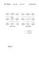
- FIG. 3illustrates a motion class tap structure in accordance with one embodiment of the present invention.
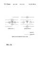
- FIG. 4illustrates an error class tap structure in accordance with one embodiment of the present invention.
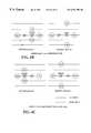
- FIGS. 5 a , 5 b and 5 cshow a basic classified adaptive error recovery with the class tap structure and filter tap structure utilized in one embodiment of the present invention.
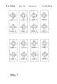
- FIGS. 6 a , 6 b , 6 c and 6 dshow various adaptive spatial class tap structures in accordance with one embodiment of the present invention.
- FIG. 7shows an example of ADRC class reduction.
- FIGS. 8 a , 8 b , 8 c and 8 dillustrate various adaptive filter tap structures in accordance with one embodiment of the present invention.
- FIG. 9shows a system block diagram of an alternate embodiment of a multiple processing system in accordance with one embodiment of the present invention.
- FIG. 10depicts a system block diagram of another embodiment of a multiple processing system in accordance with one embodiment of the present invention.
- FIG. 11illustrates a high level block diagram for a multiple processing system in accordance with one embodiment of the present invention combining error recovery processing, subsample interpolation processing, and noise reduction processing in a parallel structure.
- FIG. 12shows a system block diagram of an alternate embodiment of a multiple processing system in accordance with one embodiment of the present invention.
- FIG. 13shows an output selection truth table of one embodiment in accordance with one embodiment of the present invention.
- FIG. 14illustrates one embodiment of a method for selectively performing error recovery processing, subsample interpolation processing, and noise reduction processing in a multiple, parallel processing system.
- FIG. 15illustrates one embodiment of a generalized method for performing multiple functions on input data in a multiple, parallel processing system.
- the teachings of the present inventionare utilized to implement a multiple processing system that selectively performs different processes such as error recovery, noise reduction, and subsample interpolation.
- the present inventionis not limited to these processes and can be applied to other processes utilized to manipulate correlated data, including sound or image data.
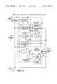
- FIG. 1is a system block diagram of one embodiment of a multiple processing system in accordance with the teachings of the present invention.
- the systemis configured to selectively perform classified adaptive error recovery and noise reduction in a parallel structure.
- Input data 101 and corresponding error flags 105are input to the system.
- the input data 101may be video image, sound, or other correlated data.
- the input data 101is digital image data represented by discrete data points that are commonly known as pixels. Each data point can be represented independently, for example, using 8-bit binary number. Data points can also be represented by other alternative representations, for example, by dividing the raw data into disjoint sets of data points, known as blocks.
- the error flag 105is used to indicate the locations within the input data 101 that contain erroneous samples.
- the error flagmay be used to indicate whether a data point being processed contains errors or is unknown, unreliable or unavailable.
- the input data 101 and error flag 105are input to the pre-processor 109 to generate pre-processed data.
- the datais pre-processed to provide estimates of input data containing errors. Such data is valuable for subsequent processing as described below.
- the pre-processed datais proposed output values of data which have corresponding error flags set (referred to herein as target data).
- the proposed value of erroneous datais generated from associated taps.
- the tapsare either one of the neighboring or peripheral data or a combination of multiple peripheral data.
- the error flagis set for the target data and not set for peripheral data horizontally adjacent to the target data, the target data is replaced with horizontal peripheral data. If the peripheral data located horizontally to the erroneous target data also contains errors, peripheral data located vertically to the target data is used. If the vertical peripheral data also contains errors, previous frame data is used.
- FIG. 2 aAn example of a pre-processing algorithm is illustrated in FIG. 2 a .
- the target pixel X 1 in the current frame 277is being pre-processed and an associated error flag has been set indicating an error with respect to X 1 .
- the peripheral data used to pre-process X 1are pixels X 0 , X 2 , X 3 and X 4 of the current frame 277 and pixel X 5 of the previous frame 279 .
- X 1 ′is the proposed value for the target data X 1 .
- the error flag E(Xi) corresponding to the peripheral data Xiand is set to 1 if the peripheral data Xi contains errors and set to zero if no error has been detected.
- step 245if the error flags corresponding to pixels X 0 and X 2 indicate no errors, then X 1 ′ is set to be the average of X 0 and X 2 , step 259 . Otherwise; at step 247 , if the error flag corresponding to X 0 is set, then X 1 ′ is set to equal X 2 , step 261 . At step 249 , if the error flag for X 2 is set, then X 1 ′ is set to equal X 0 , step 263 .
- X 1 ′is set to be the average of X 3 and X 4 , step 265 .
- X 1 ′is set to equal X 4 , step 269 .
- X 1 ′is set to equal X 3 , step 271 .
- X 1 ′is set to equal a co-located pixel from a prior frame X 5 , step 257 .
- FIG. 2 bAn alternate pre-processing algorithm is illustrated in FIG. 2 b .
- motion informationis used to determine the peripheral data to be used to generate the pre-processed output X 1 ′. For example, if motion is detected, the peripheral data of the current frame to use are identified in frame 272 and the data of the previous frame to use is shown in frame 274 . If no motion is detected, i.e., the data is stationary and has not changed, field information may be used as illustrated by frame 276 . Previous frame data of frame 278 is also used. Frames 272 , 274 , 276 and 278 are just one example of taps to use. Alternate tap structures may also be used.
- the motion valueis determined by the preprocessor 109 (FIG. 1 ).
- the systemmay include a control input indicative of motion coupled to the pre-processor.
- motionis detected by averaging motion information from error free peripheral data and comparing the averaged motion value to a predetermined threshold indicative of motion.
- the peripheral datais evaluated to determine whether the motion threshold has been met.
- the tapsare selected based on whether motion has been detected. Thus, in the present embodiment and as noted above, if motion is detected, the taps illustrated in frames 272 and 274 are used; if motion is not detected, the taps illustrated in frames 276 and 278 are used.
- steps 277 , 279 , 281 , 283 , 285 , 287 , 289 , 291 , 293 , 295 , 297 , 298 and 299are selectively performed to generate the output X 1 ′ based upon the selected taps.
- the input data 101is input to error recovery processing circuitry 110 and noise reduction processing circuitry 112 .
- the circuitries 110 , 112process the data in parallel and forward the processed data to the selector 141 .
- the output 143is selected by selector 141 based upon the value of the error flag 105 and outputs of error recovery processing circuitry 110 and noise reduction processing circuitry 112 .
- Error recovery processing circuitry 110includes a plurality of class generators 115 , 117 , 121 , which generate class identifiers used to select filter taps and coefficients used by filter 127 to process a target data.
- Target datais the particular data whose value is to be determined or estimated.
- a classcan be thought of as a collection of specific values used to describe certain characteristics of the target data.
- a classmay be defined based on one or more characteristics of the target data.
- a classmay also be defined based on one or more characteristics of the group containing the target data.
- the present inventionwill be discussed in terms of a motion class, an error class and a spatial class. Other types of classes can be used.
- a motion classcan be thought of as a collection of specific values used to describe the motion characteristic of the target data.
- the motion classis defined based on the different levels of motion of the block containing the target data, for example, no motion in the block, little motion in the block, or large motion in the block.
- An error classcan be thought of as a collection of specific values used to describe the various distribution patterns of erroneous data in the neighborhood of the target data.
- an error classis defined to indicate whether the data adjacent to the target data are erroneous.
- a spatial classcan be thought of as a collection of specific values used to describe the spatial characteristic of the target data. Spatial classification of the data may be determined using Adaptive Dynamic Range Coding (ADRC), for purposes of the discussion herein, a spatial class determined by ADRC is referred to as an ADRC class, Differential PCM, Vector Quantization, Discrete Cosine Transform, etc.
- ADRCAdaptive Dynamic Range Coding
- Coefficient Memory 119stores coefficients utilized by filter 127 ; the coefficients to be used are determined by the class identifiers (IDs) generated by class generators 115 , 117 , 121 .
- a class IDcan be thought of as a specific value within the class that is used to describe and differentiate the target data from other data with respect to a particular characteristic.
- a class IDmay be represented by a number, a symbol, or a code within a defined range.
- a motion class IDis a specific value within the motion class used to indicate a particular level of motion quantity of the target data. For example, a motion class ID of “0” may be defined to indicate no motion, a motion class ID of “3” may be defined to indicate large motion.
- an error class IDis a specific value within the error class used to describe a particular distribution pattern of erroneous data in the neighborhood of the target data. For example, an error class ID of “0” may be defined to indicate that there is no erroneous data to the left and to the right of the target data; an error class ID of “1” may be defined to indicate that the data to the left of the target data is erroneous, etc.
- a spatial class IDis a specific value within the spatial class used to classify the spatial pattern of the group or block containing the target data.
- An ADRC class IDis an example of a spatial class ID.
- ADRC class generator 115motion class generator 117 and error class generator 121 are used. Other class generators may be used.
- the class generatorsoutput a class ID based upon the pre-processed input data.
- error class generator 121generates an error class ID based upon the value of the error flag 105 .
- Motion class generator 117generates a motion class ID based upon the pre-processed data and the value of the error flag 105 .
- ADRC class generator 115generates an ADRC class ID based upon the pre-processed data, the motion class ID, and the error class ID. A detailed description of the generation of the class ID of different classes mentioned above is provided below.
- the motion class generator 117generates a motion class ID based on the pre-processed data and the value of the error flag 105 .
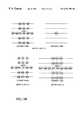
- FIG. 3shows an example of motion class tap structures having 8 taps in the neighborhood of the target data. The accumulated temporal difference of the 8 taps are calculated according to formula 1 below and the motion class ID is generated according to formula 2.
- the motion classis defined to have four different motion class IDs 0 , 1 , 2 , and 3 , based on three pre-defined threshold values th 0 , th 1 , and th 2 .
- fdrepresents an accumulated temporal difference
- x irepresents motion class tap data of the current frame
- x′ irepresents the previous frame tap data corresponding to the current frame
- mcrepresents the motion class ID.
- three thresholds, th 0 , th 1 , th 2are used for motion classification.
- th 0equals 3
- th 1equals 8
- th 2equals 24.
- the error class generator 121performs error classification to generate an error class ID according to the value of the error flag 105 .
- FIG. 4shows an example of an error class with four different error class IDs describing four different distribution patterns of erroneous data in the neighborhood of the target data.
- an error class ID of 0indicates that there is no erroneous data to the left and to the right of the target data (independent error case); an error class ID of 1 means there is erroneous data to the left of the target data (left erroneous case); an error class ID of 2 means there is erroneous data to the right of the target data (right erroneous case); and an error class ID of 3 means there are erroneous data to the left and to the right of the target data (consecutive erroneous case).
- the Adaptive Dynamic Range Coding (ADRC) class generator 115performs ADRC classification to generate an ADRC class ID.
- ADRCAdaptive Dynamic Range Coding
- FIG. 5an example is shown where the number of class taps is four.
- 16 ADRC class IDsare available as given by formula 5.
- An ADRC valueis computed by formula 4, using a local dynamic range (DR) computed by formula 3, as shown below:
- DRrepresents the dynamic range of the four data area
- MAXrepresents the maximum level of the four data
- MINrepresents the minimum level of the four data
- q iis the ADRC encoded data
- Qis the number of quantization bits
- ⁇ . ⁇represents a truncation operation performed on the value within the square brackets
- ccorresponds to an ADRC class ID.
- an adaptive class tap structureis used to determine the ADRC class ID of the target data.
- An adaptive class tap structureis a class tap structure used in the multiple classification scheme.
- An adaptive class tap structureis used to more accurately represent the class tap structure of the area containing the target data since it describes more than one characteristic of the target data.
- spatial class tapsare selected based upon the motion class ID and the error class ID of the target data as well as the preprocessed, data.
- FIGS. 6 a , 6 b , 6 c , and 6 dshow examples of various adaptive spatial class tap structures based on different combinations of the motion class ID and the error class ID.
- a proper ADRC adaptive spatial class tap structureis chosen according to the motion class ID generated by the motion class generator 117 and the error class ID generated by the error class generator 121 .
- An ADRC class ID for the target datais generated based on the chosen adaptive class tap structure using the formulas described above.
- a spatial class reductionis used in the classified adaptive error recovery method.
- the ADRC classis introduced as one type of spatial classification, and is given by [formula 5].
- ccorresponds to the ADRC class ID
- q iis the quantized data
- Qis the number of quantization bits based on [formula 3] and [formula 4].
- [formula 6]corresponds to a one's complement operation of binary data of the ADRC code, which is related to the symmetric characteristics of each signal wave form. Since ADRC classification is a normalization of the target signal wave form, two wave forms that have the relation of 1 ′ complement in each ADRC code can be classified in the same class ID. It has been found that the number of ADRC class IDs may be halved by this reduction process.
- an adaptive filter tap structureis a set of taps defined based on one or more corresponding classes.
- an adaptive filter tap structuremay be defined based on a motion class ID, an error class ID, or both.
- a multiple classcan be thought of as a collection of specific values or sets of values used to describe at least two different characteristics of the target data.
- An exemplary definition of a multiple classis a combination of at least two different classes.
- a particular classification schememay define a multiple class as a combination of an error class, a motion class, and an ADRC class.
- a multiple class IDis a specific value or specific set of values within the classes used to describe the target data with respect to at least two different characteristics of the target data.
- a multiple class IDis represented by a set of different class IDs. For example, if the multiple class is defined as a combination of an error class, a motion class, and an ADRC class, a multiple class ID can be represented by a simple concatenation of these different class IDs.
- the multiple class IDcan be used as, or translated into, the memory address to locate the proper filter coefficients and other information that are used to determine or estimate the value of the target data.
- a simple concatenation of different class IDs for the multiple class IDis used as the memory address.
- the adaptive filter tap structureis defined based on the motion class ID and the error class ID of the target data.
- FIGS. 8 a , 8 b , 8 c , and 8 dshow various adaptive filter tap structures corresponding to different combinations of a motion class ID and an error class ID.
- the adaptive filter tap structure corresponding to the error class ID of 0 and the motion class ID of 3has four coefficient taps that are the same, w 3 .
- some tap coefficientscan be replaced by the same coefficient.
- FIG. 8 dthere are four w 3 coefficients that are located at horizontally and vertically symmetric locations and there are two w 4 coefficients at horizontally symmetric locations.
- one w 3 coefficientcan represent four taps and one w 4 coefficient can represent two taps.
- 14 coefficientscan represent 18 taps.
- This methodcan reduce coefficient memory and filtering hardware such as adders and multipliers. This method is referred to as the filter tap expansion.
- the filter tap expansion definitionis achieved by evaluation of the coefficient distribution and the visual results.
- the proper filter tap structure for a particular target datacan be retrieved from a location in a memory device such as a random access memory (RAM), using the motion class ID and the error class ID as the memory address.
- a memory devicesuch as a random access memory (RAM)
- the proper filter tap structure for a target datacan be generated or computed by other methods in accordance with the present invention.
- the coefficient memory 119provides a set of filter coefficients corresponding to the error class ID, the motion class ID, and the ADRC class ID of the target data. For each combination of an error class ID, a motion class ID, and an ADRC class ID, a corresponding filter is prepared for the adaptive processing.
- the filtercan be represented by a set of filter coefficients.
- the filter coefficientscan be generated by a training process that occurs as a preparation process prior to filtering.
- the filter coefficients corresponding to the different combinations of error, motion, and ADRC class IDsare stored in a memory device such as a random access memory (RAM).
- Output datais generated according to the linear combination operation in formula 7 below:
- x iis input filter tap data
- w icorresponds to each filter coefficient
- yis the output data after error recovery.
- Filter coefficients for each class ID, or each multiple class ID in a multiple classification schemeare generated by a training process that occurs before the error recovery process. For example, training may be achieved according to the following criterion: min W ⁇ ⁇ X ⁇ W - Y ⁇ 2 [formula 8]
- X, W, and Yare the following matrices: X is the input filter tap data matrix defined by [formula 9], W is the coefficient matrix defined by [formula 10], and Y corresponds to the target data matrix defined by [formula 11].
- X( x 11 x 12 ⁇ x 1 ⁇ n x 21 x 22 ⁇ x 2 ⁇ n ⁇ ⁇ ⁇ ⁇ x m1 x m2 ⁇ x mn ) [formula 9]
- W( w 1 w 2 ⁇ w n ) [formula 10]
- Y( y 1 y 2 ⁇ y m ) [formula 11]
- the coefficient w ican be obtained according to [formula 8] to minimize the estimation errors against target data.
- One set of coefficients corresponding to each class ID that estimates the target datamay be determined by the training method described above.
- the filter 127performs error recovery filtering to produce error recovered data based upon the filter tap data and the filter coefficients.
- x iis the filter tap data generated by the filter tap selector 125 , using 14-tap adaptive filter tap structure as described previously, w i corresponds to each filter coefficient of the set of trained coefficients retrieved from the coefficient memory 119 , and y is the output data of the filter 127 after error recovery filtering.
- a process known as an inter-frame processis used to perform noise reduction.
- the pre-processed datais input to the multiplication logic 129 which performs a multiplication operation on the pre-processed data, using (1-K) as the weight, where K is a predetermined constant.
- the data retrieved from the frame memory 135is input to the multiplication logic 133 which performs a multiplication operation on the data retrieved from the frame memory, using K as the weight.
- the data generated by the multiplication logic 129 and the multiplication logic 133are added by the adder 131 to produce noise-reduced data for stationary pre-processed data. This process is also known as cross-fade operation.
- a process known as intra-field processcan be used to perform noise reduction.
- the pre-processed datais input to a median filter 137 which generates noise-reduced data corresponding to the preprocessed data.
- the motion detection logic 139checks the level of motion in the pre-processed data to generate a motion indicator depending on whether the level of motion in the pre-processed data exceeds a predetermined threshold value. For example, if the level of motion exceeds the predetermined threshold value, the motion indicator is set to “1”, otherwise the motion indicator is set to “0”.
- the selector 141selects either error recovered data or noise-reduced data based on the value of error flag 105 and the value of the motion indicator to produce the proper output data 143 of the system.
- the selector 141selects the error recovered data generated by the filter 127 as the output data 143 of the system if the error flag is set, for example, if the value of the error flag is “1”. If the error flag is not set and the motion indicator is set, the selector 141 selects the output of the median filter as the output data 143 of the system. If the error flag is not set and the motion indicator is not set, the selector 141 selects the output of the adder 131 as the output data 143 of the system.
- the multiple processing system illustrated in FIG. 1can selectively perform classified adaptive error recovery processing or noise reduction processing according to the value of the error flag.
- FIG. 9is a simplified block diagram of an alternate embodiment of a multiple processing system which is configured to selectively perform classified adaptive error recovery processing and noise reduction processing m a parallel structure. Since both error recovery processing and noise reduction processing include motion adaptive processing, the motion adaptive processing hardware can be shared between error recovery processing and noise reduction processing, which further reduces the hardware complexity and redundancy in a multiple processing system.
- the motion class generator 917is shared by the error recovery circuit and the noise reduction circuit, thus eliminating the need for a separate motion detection logic that was required in the other configuration shown in FIG. 1 .
- the error recovery processingis achieved in the same way described above.
- Input data 901 and corresponding error flags 905are input to the system.
- the input data 901is pre-processed by the pre-processor 909 to generate pre-processed data according to the input data 901 and the value of the error flag 905 as described above.
- the motion class generator 917generates a motion class ID based on the pre-processed data and the value of the error flag 905 .
- the motion classis defined to have four different motion class IDs: 0 , 1 , 2 , and 3 , based on three pre-defined threshold values of 3 , 8 , and 24 .
- the error class generator 921performs error classification to generate an error class ID according to the value of the error flag, as described above.
- the error classis defined to have four different error class IDs as follows: the error class ID of 0 (independent error case); the error class ID of 1 (left erroneous case); the error class ID of 2 (right erroneous case); and the error class ID of 3 (consecutive erroneous case).
- the Adaptive Dynamic Range Coding (ADRC) class generator 913performs ADRC classification to generate an ADRC class ID according to the pre-processed data, the motion class ID, and the error class ID.
- ADRCAdaptive Dynamic Range Coding
- One embodiment of an ADRC classification process that utilizes an adaptive class tap structure based on the motion class ID and the error class ID and implements a spatial class reduction techniqueis described above. In the present example, the number of ADRC class IDs is 8 .
- the filter tap selector 925selects an appropriate adaptive filter tap structure for the target data based on the motion class ID and the error class ID of the target data.
- a 14-tap filter tap structureis used.
- the proper filter tap structure corresponding to the target datais retrieved from a memory device such as a random access memory (RAM), using the motion class ID and the error class ID as the memory address.
- the proper filter tap structure for a target datacan be generated or computed by other methods in accordance with the teachings of the present invention.
- the coefficient memory 941generates a set of filter coefficients corresponding to the error class ID, the motion class ID, and the ADRC class ID of the target data.
- the different sets of filter coefficients corresponding to different combinations of error, motion, and ADRC class IDsare obtained through a training process prior to the error recovery process and stored in memory device such as a RAM.
- the combination of an error class ID, a motion class ID, and an ADRC class IDare used as the memory address to point to the correct memory location from which the proper filter coefficients corresponding to the target data are retrieved.
- the memory addressis a simple concatenation of an error class ID, a motion class ID, and an ADRC class ID.
- the memory addresscan also be computed as a function of an error class ID, a motion class ID, and an ADRC class ID.
- the filter 943performs error recovery filtering as described above to produce error recovered data based on the filter tap data and the filter coefficients.
- the noise reduction circuit 930 in FIG. 9performs noise reduction processing as described above with respect to FIG. 1, with one modification. Instead of using a separate motion detection logic to detect a level of motion in the pre-processed data and generate a motion indicator, the noise reduction circuit 930 uses the motion class generator 917 to generate a motion class ID that is also input to the selector 961 . In this example, since the motion class generator 917 can generate one of four different motion class IDs, one or more of these motion class IDs can be used to indicate motion data while the other motion class IDs can be used to indicate stationary data for noise-reduced data selection purpose.
- the motion class ID of 0is used to indicate stationary data and other motion class IDs, namely 1 , 2 , and 3 are used to indicate motion data.
- the selector 961selects either error recovered data or noise-reduced data based on the value of the error flag 905 and the motion class ID generated by the motion class generator 917 . For example, if the value of the error flag is 1 , the error recovered data generated by the filter 943 is selected by the selector 961 as the output data 971 of the system. If the value of the error flag is not 1 and the motion class ID is 0 , the selector 961 selects the output of the adder 931 as the output data 971 of the system.
- the selector 961selects the output of the median filter 947 as the output data 971 of the system.
- the multiple processing system shown in FIG. 9can selectively perform classified adaptive error recovery processing or noise reduction processing according to the value of the error flag.
- FIG. 10illustrates a block diagram for another embodiment of a multiple processing system that can selectively perform classified adaptive subsample interpolation processing and motion adaptive noise reduction processing in a parallel structure. Since both classified adaptive subsample interpolation and motion adaptive noise reduction include motion adaptive processing, the motion adaptive hardware can be shared between subsample interpolation processing and noise reduction processing, thus reducing the hardware complexity and hardware redundancy in the overall system.
- the motion class generator 1013is shared by both subsample interpolation processing and noise reduction processing circuits, thus eliminating the need for a separate motion detection device that would normally be required in a noise reduction circuit, as shown in FIG. 1 .
- the classified adaptive subsample interpolation processingis performed as follows.
- Input data 1001 and corresponding subsample flags 1003are input to the system.
- input data 1001may be image, sound, or other correlated data.
- input data 1001is digital image data represented by discrete data points commonly known as pixels that are divided into disjoint sets known as blocks.
- the subsample flag 1003is used to indicate the locations within the input data 1001 that contain samples to be interpolated.
- the subsample flag 1003may be used to indicate whether a particular data point being processed is a point to be interpolated.
- the motion class generator 1013generates a motion class ID based on the input data 1001 .
- the motion classis defined to have four different motion class IDs: 0 , 1 , 2 , and 3 , based on three pre-defined threshold values of 3 , 8 , and 24 .
- the Adaptive Dynamic Range Coding (ADRC) class generator 1005performs ADRC classification to generate an ADRC class ID according to the input data 1001 , the motion class ID, and the value of the subsample flag 1003 .
- ADRCAdaptive Dynamic Range Coding
- One embodiment of an ADRC classification process that utilizes an adaptive class tap structure based on a motion class ID and implements a spatial class reduction techniqueis described above. In this example, the number of ADRC class IDs is 8 .
- the filter tap selector 1009selects an appropriate adaptive filter tap structure for the target data based on the motion class ID and the value of the subsample flag 1003 .
- the filter tap structure corresponding to the target datais retrieved from a memory device such as a random access memory (RAM), using the motion class ID and the value of the subsample flag 1003 as the memory address.
- a memory devicesuch as a random access memory (RAM)
- the filter tap structure to be used for a target datacan be generated or computed by other methods in accordance with the present invention.
- the coefficient memory 1031generates a set of filter coefficients corresponding to the motion class ID and the ADRC class ID of the target data.
- the different sets of filter coefficients corresponding to different combinations of motion and ADRC class IDsare preferably obtained by a training process prior to the subsample interpolation process and stored in a memory device such as a RAM.
- the training process to generate different sets of filter coefficientsis described above.
- the combination of a motion class ID and an ADRC class IDmay be used as the memory address to point to the correct memory location from which the proper filter coefficients corresponding to the target data are retrieved.
- the memory addressis a simple concatenation of a motion class ID and an ADRC class ID.
- the memory addresscan also be computed as a function of a motion class ID and an ADRC class ID.
- the filter 1033performs filtering as described previously to produce subsample interpolated-data based on the filter tap data and the filter coefficients.
- the noise reduction circuit 1030 in FIG. 10performs noise reduction processing as described above with respect to FIGS. 8 a , 8 b , 8 c , and 8 d .
- the motion class generator 1013can generate one of four different motion class IDs, one or more of these motion class IDs can be used to indicate motion data while the other motion class IDs can be used to indicate stationary data for noise-reduced data selection purpose.
- the motion class ID of 0is used to indicate stationary data and other motion class IDs, namely 1 , 2 , and 3 are used to indicate motion data.
- the selector 1061selects either subsample interpolated data or noise-reduced data based on the value of the subsample flag 1003 and the motion class ID generated by the motion class generator 1013 . For example, if the value of the subsample flag is 1 , the subsample interpolated data generated by the filter 1033 is selected by the selector 1061 as the output data 1071 of the system. If the value of the subsample flag is not 1 and the motion class ID is 0 , the selector 1061 selects the output of the adder 1021 as the output data 1071 of the system.
- the selector 1061selects the output of the median filter 1037 as the output data 1071 of the system.
- the multiple processing system shown in FIG. 10can selectively perform classified adaptive subsample interpolation and noise reduction processing according to the value of the subsample flag.
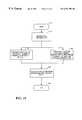
- FIG. 11shows a high level system block diagram for another embodiment of a multiple processing system in accordance with the present invention that selectively performs error recovery processing, subsample interpolation processing, and noise reduction processing in a parallel structure.
- Input data 1101 and corresponding control input 1105are input to the system.
- the input data 1101may be image, sound, or other correlated data.
- the input data 1101is digital image data represented by discrete data points that are divided into disjoint sets known as blocks.
- the control input 1105may contain a plurality of input processing selection signals such as flags.
- the control input 1105includes an error flag and a subsample flag that are input to the selector 1131 .
- the motion evaluation device 1109detects a level of motion in the input data 1101 and generate a motion indicator based on the level of motion detected.
- the motion indicatormay have different values depending on the level of motion detected. For example, a value of 0 may be defined to indicate no motion, a value of 1 may be defined to indicate little motion, etc.
- the motion evaluation device 1109may be configured to work as a motion class generator which generates a motion class ID based on the level of motion detected. As mentioned previously, a motion class generator can generate different class IDs based on the different levels of motion detected.
- the error recovery circuit 1113performs error recovery processing to generate error recovered data based on the input data 1101 and the output of the motion evaluation device 1109 .
- the error recovery circuit 1113may be a conventional error recovery system or a classified adaptive error recovery system described previously.
- the subsample interpolation circuit 1117performs subsample interpolation processing to produce subsample interpolated data based on the input data 1101 and the output of the motion evaluation device 1109 .
- the subsample interpolation circuit 1117may be a conventional interpolation system or a classified adaptive subsample interpolation system which is described in detail above.
- the noise reduction circuit 1119performs noise reduction processing as described above to produce noise-reduced data based on the input data 1101 and the output of the motion evaluation device 1109 .
- the selector 1131selects as output data 1141 of the system either the error recovered data, the subsample interpolated data, or the noise reduced data based on the value of the control input 1105 . For example, if the control input 1105 contains an error flag and a subsample flag, the selector 1131 may perform the selection as follows. If the value of the error flag is “1”, the error recovered data is selected as the output data 1141 .
- the system shown in FIG. 11can selectively perform error recovery, subsample interpolation, and noise reduction, in a parallel structure, based on the value of the control input 1105 .
- FIG. 12illustrates a block diagram for another embodiment of a multiple processing system that selectively performs, in a parallel structure, classified adaptive error recovery processing, classified adaptive subsample interpolation processing, and motion adaptive noise reduction processing. Since classified adaptive error recovery processing and classified adaptive subsample interpolation processing contain similar structures, hardware required for these two processes can be shared including but not limited to the ADRC class generator 1221 , the filter tap selector 1225 , the motion class generator 1227 , the coefficient memory 1241 , and the filter 1243 . In addition, noise reduction processing also shares the motion class generator 1227 .
- a configuration as illustrated in FIG. 12eliminates the need for separate and redundant hardware that would normally be required if the different circuits mentioned above are operated separately or in serial, pipelined structures. As a result, hardware costs and complexity in the overall multiple processing system can be significantly reduced while operational efficiency and processing flexibility can be significantly increased.
- Input data 1201a subsample flag 1203 , and an error flag 1205 are input to the multiple processing system.
- Input data 1201may be image, sound, or other correlated data.
- input data 1201is digital image data represented by discrete data points, commonly known as pixels, that are divided into disjoint sets known as blocks.
- the subsample flag 1203is used to indicate the locations in the input data 1201 that contain the target data to be interpolated.
- the subsample flag 1203may be defined to have a value of “1” if the data being processed is to be interpolated and to have a value of “0” otherwise.
- the error flag 1205is used to indicate the locations in the input data that contain errors.
- the error flag 1205may be defined to have two different values depending on the whether the data being processed contains errors. In this example, the value of the error flag 1205 is “1” if the data being processed contain errors and the value of the error flag 1205 is “0” if the data being processed is error-free.
- the input data 1201is pre-processed by the preprocessor 1211 to generate the pre-processed data according to the input data 1201 and the value of the error flag 1205 .
- the generation of pre-processed datais described previously.
- the motion class generator 1227performs motion classification to generate a motion class ID based on the pre-processed data and the value of the error flag 1205 .
- the motion classis defined to have four different motion class IDs: 0 , 1 , 2 , and 3 , based on three predefined threshold values of 3 , 8 , and 24 .
- the error class generator 1223performs error classification to generate an error class ID according to the value of the error flag 1205 and the value of the subsample flag 1203 .
- the error classis defined to have four different error class IDs as follows: the error class ID of “0” (independent error case); the error class ID of “1” (left erroneous case); the error class ID of “2” (right erroneous case); and the error class ID of “3” (consecutive erroneous case). If the error flag is set, e.g., having a value of 1, the error class generator 1223 performs error classification as described above to generate an error class ID. If the error flag is not set, e.g., having a value of 0, the error class generator generates a predetermined value that will be used in addressing the subsample memory area in the coefficient memory 1241 , which will be discussed in detail subsequently.
- the Adaptive Dynamic Range Coding (ADRC) class generator 1221performs ADRC classification to generate an ADRC class ID according to the pre-processed data, the motion class ID, the error class ID, and the value of the subsample flag 1203 .
- ADRCAdaptive Dynamic Range Coding
- One embodiment of an ADRC classification process using an adaptive class tap structure based on a motion class ID and an error class ID and implementing a spatial class reduction techniqueis described above. If the subsample flag 1203 is set, an adaptive class tap structure corresponding to the target data to be used for subsample interpolation processing is chosen. If the subsample flag 1203 is not set, an adaptive class tap structure corresponding to the target data to be used for error recovery processing is chosen. In this example, the ADRC class is defined to have eight different ADRC class IDs.
- the filter tap selector 1225selects an appropriate adaptive filter tap structure for the target data based on the motion class ID, the error class ID, and the value of the subsample flag 1203 . If the subsample flag 1203 is set, a filter tap structure corresponding to the target data to be used for subsample interpolation processing is selected. If the subsample flag 1203 is not set, a filter tap structure corresponding to the target data to be used for error recovery processing is selected. In one embodiment, a 14-tap filter tap structure is used.
- the filter tap structure corresponding to the target datais retrieved from a memory device such as a random access memory (RAM), using the value of the subsample flag 1203 , the motion class ID, and the error class ID as the memory address.
- a memory devicesuch as a random access memory (RAM)
- the filter tap structure to be used for a particular target datacan be generated or computed by other methods in accordance with the present invention.
- the coefficient memory 1241generates a set of filter coefficients corresponding to the value of the subsample flag 1203 , the error class ID, the motion class ID, and the ADRC class ID of the target data.
- the different sets of filter coefficients corresponding to different combinations of different class IDsare obtained through a training process and stored in memory device such as a RAM.
- the filter coefficients to be used for error recovery processingare stored in one area of the coefficient memory 1241 and the filter coefficients to be used for subsample interpolation processing are stored in a different area of the coefficient memory 1241 .
- the value of the subsample flagis used to point to the correct area in the coefficient memory from which the appropriate filter coefficients for either error recovery or subsample interpolation are to be retrieved.
- the combination of the value of the subsample flag 1203 , an error class ID, a motion class ID, and an ADRC class IDis used as the memory address to point to the correct memory location from which the proper filter coefficients corresponding to the target data are retrieved.
- a simple concatenation of the value of the subsample flag 1203 , the error class ID, the motion class ID, and the ADRC class IDis used as the memory address to retrieve the proper filter coefficients.
- the memory addresscan also be computed as a function of the value of the subsample flag 1203 , the error class ID, the motion class ID, and the ADRC class ID.
- the filter 1243performs filtering as described above using the filter tap data generated by the filter tap selector 1225 and the filter coefficients provided by the coefficient memory 1241 to produce either error recovered data or subsample interpolated data.
- the noise reduction circuit 1230 in FIG. 12performs noise reduction processing as described above with respect to FIGS. 1, 9 , and 10 .
- the motion class generator 1227can generate one of four different motion class IDs, one or more of these motion class IDs can be used to indicate motion data while the other motion class IDs can be used to indicate stationary data for noise-reduced data selection purpose.
- the motion class ID of 0is used to indicate stationary data and other motion class IDs, namely 1 , 2 , and 3 are used to indicate motion data.
- the selector 1261selects as output data 1271 of the system either error recovered data, subsample interpolated data, or noise-reduced data based on the value of the error flag 1205 , value of the subsample flag 1203 and the motion class ID generated by the motion class generator 1227 .
- the selector 1261performs the output selection process according to the output selection truth table shown in FIG. 13 .
- FIG. 13illustrates an output selection truth table for selecting proper data generated by the multiple processing system shown in FIG. 12 above.
- the selection of proper output datais accomplished by examining the value of the error flag 1301 , the value of the subsample flag 1305 , and the motion class ID 1309 .
- the error flag 1301has a value of 1 when it is set and a value of 0 when it is not set.
- the subsample flag 1305is assigned a value of 1 when it is set and a value of 0 when it is not set.
- a motion class ID of 0indicates stationary data while another motion class, for example, motion class of 1 or 2 indicates motion data. Error-recovered data is selected if the error flag 1301 is set.
- Subsample-interpolated datais selected if the error flag 1301 is not set and the subsample flag 1305 is set.
- Noise-reduced stationary datais selected if neither the error flag 1301 nor the subsample flag 1305 is set, and the motion class ID 1309 has a value of 0.
- noise-reduced motion datais selected if neither the error flag 1301 nor the subsample flag 1305 is set, and the motion class ID 1309 is not 0 .
- the multiple processing system shown in FIG. 12can selectively perform classified adaptive error recovery, classified adaptive subsample interpolation, and noise reduction based on the value of the error flag 1205 and the value of the subsample flag 1203 .
- FIG. 14shows a method for selectively performing, in a parallel manner, error recovery processing, subsample interpolation processing, and noise reduction processing in accordance with the teachings of the present invention.
- Input stream of datais received at 1409 .
- Error recovery processingis performed on the input stream of data at 1421 to generate error-recovered data.
- subsample interpolation processingis performed on the input stream of data to generate subsample-interpolated data.
- Noise reduction processingis performed on the input stream of data at 1429 to generate noise-reduced data.
- a selection of either error-recovered data, subsample-interpolated data, or noise-reduced datais performed according to a control input to generate an output of data.
- FIG. 15illustrates a generalized method for selectively performing, in a parallel manner, different functions on an input stream of data in accordance with the teachings of the present invention.
- the input stream of datais received.
- a first functionis performed on the input stream of data at 1521 to generate a first output of data.
- at least one additional different functionis performed on the input stream of data to generate at least one additional output of data.
- a selection of either the first output of data or the additional output of datais performed based upon a control input to generate proper data output.
Landscapes
- Engineering & Computer Science (AREA)
- Multimedia (AREA)
- Signal Processing (AREA)
- Television Systems (AREA)
Abstract
Description


Claims (15)
Priority Applications (3)
| Application Number | Priority Date | Filing Date | Title |
|---|---|---|---|
| US09/249,493US6591398B1 (en) | 1999-02-12 | 1999-02-12 | Multiple processing system |
| PCT/US2000/003738WO2000048406A1 (en) | 1999-02-12 | 2000-02-11 | Multiple processing system |
| AU29932/00AAU2993200A (en) | 1999-02-12 | 2000-02-11 | Multiple processing system |
Applications Claiming Priority (1)
| Application Number | Priority Date | Filing Date | Title |
|---|---|---|---|
| US09/249,493US6591398B1 (en) | 1999-02-12 | 1999-02-12 | Multiple processing system |
Publications (1)
| Publication Number | Publication Date |
|---|---|
| US6591398B1true US6591398B1 (en) | 2003-07-08 |
Family
ID=22943687
Family Applications (1)
| Application Number | Title | Priority Date | Filing Date |
|---|---|---|---|
| US09/249,493Expired - Fee RelatedUS6591398B1 (en) | 1999-02-12 | 1999-02-12 | Multiple processing system |
Country Status (3)
| Country | Link |
|---|---|
| US (1) | US6591398B1 (en) |
| AU (1) | AU2993200A (en) |
| WO (1) | WO2000048406A1 (en) |
Cited By (16)
| Publication number | Priority date | Publication date | Assignee | Title |
|---|---|---|---|---|
| US20030081144A1 (en)* | 2001-10-22 | 2003-05-01 | Nader Mohsenian | Video data de-interlacing using perceptually-tuned interpolation scheme |
| US20030108252A1 (en)* | 2001-12-11 | 2003-06-12 | James J. Carrig | Resolution enhancement for images stored in a database |
| US20030210833A1 (en)* | 2002-05-13 | 2003-11-13 | Straney Gale L. | Locating point of interest in an impaired image |
| US20040070685A1 (en)* | 2002-07-03 | 2004-04-15 | Tetsujiro Kondo | Method and apparatus for processing information, storage medium, and program |
| US20050036061A1 (en)* | 2003-05-01 | 2005-02-17 | Fazzini Paolo Guiseppe | De-interlacing of video data |
| FR2872973A1 (en)* | 2004-07-06 | 2006-01-13 | Thomson Licensing Sa | METHOD OR DEVICE FOR CODING A SEQUENCE OF SOURCE IMAGES |
| WO2006108765A1 (en)* | 2005-04-12 | 2006-10-19 | Siemens Aktiengesellschaft | Adaptive interpolation in image or video encoding |
| US20070017647A1 (en)* | 2003-02-11 | 2007-01-25 | Giesecke & Devrient Gmbh | Security paper and method for the production thereof |
| US20070229709A1 (en)* | 2006-03-30 | 2007-10-04 | Mitsubishi Electric Corporation | Noise reducer, noise reducing method, and video signal display apparatus |
| US20070291178A1 (en)* | 2006-06-14 | 2007-12-20 | Po-Wei Chao | Noise reduction apparatus for image signal and method thereof |
| US7324709B1 (en)* | 2001-07-13 | 2008-01-29 | Pixelworks, Inc. | Method and apparatus for two-dimensional image scaling |
| US20080225953A1 (en)* | 2006-01-10 | 2008-09-18 | Krishna Ratakonda | Bandwidth adaptive stream selection |
| US7629982B1 (en)* | 2005-04-12 | 2009-12-08 | Nvidia Corporation | Optimized alpha blend for anti-aliased render |
| US20120300849A1 (en)* | 2010-01-12 | 2012-11-29 | Yukinobu Yasugi | Encoder apparatus, decoder apparatus, and data structure |
| US8346006B1 (en)* | 2008-09-17 | 2013-01-01 | Adobe Systems Incorporated | Real time auto-tagging system |
| US20220237074A1 (en)* | 2020-11-25 | 2022-07-28 | International Business Machines Corporation | Data quality-based computations for kpis derived from time-series data |
Citations (124)
| Publication number | Priority date | Publication date | Assignee | Title |
|---|---|---|---|---|
| US3311879A (en) | 1963-04-18 | 1967-03-28 | Ibm | Error checking system for variable length data |
| US3805232A (en) | 1972-01-24 | 1974-04-16 | Honeywell Inf Systems | Encoder/decoder for code words of variable length |
| US4361853A (en) | 1977-04-14 | 1982-11-30 | Telediffusion De France | System for reducing the visibility of the noise in television pictures |
| US4381519A (en) | 1980-09-18 | 1983-04-26 | Sony Corporation | Error concealment in digital television signals |
| US4419693A (en) | 1980-04-02 | 1983-12-06 | Sony Corporation | Error concealment in digital television signals |
| US4438438A (en) | 1979-12-24 | 1984-03-20 | Fried. Krupp Gesellschaft Mit Beschrankter Haftung | Method for displaying a battle situation |
| US4532628A (en) | 1983-02-28 | 1985-07-30 | The Perkin-Elmer Corporation | System for periodically reading all memory locations to detect errors |
| US4574393A (en) | 1983-04-14 | 1986-03-04 | Blackwell George F | Gray scale image processor |
| US4703351A (en) | 1984-08-22 | 1987-10-27 | Sony Corporation | Apparatus for an efficient coding of television signals |
| US4703352A (en) | 1984-12-19 | 1987-10-27 | Sony Corporation | High efficiency technique for coding a digital video signal |
| US4710811A (en) | 1984-12-21 | 1987-12-01 | Sony Corporation | Highly efficient coding apparatus for a digital video signal |
| US4722003A (en) | 1985-11-29 | 1988-01-26 | Sony Corporation | High efficiency coding apparatus |
| US4729021A (en) | 1985-11-05 | 1988-03-01 | Sony Corporation | High efficiency technique for coding a digital video signal |
| US4772947A (en) | 1985-12-18 | 1988-09-20 | Sony Corporation | Method and apparatus for transmitting compression video data and decoding the same for reconstructing an image from the received data |
| US4788589A (en) | 1985-11-30 | 1988-11-29 | Sony Corporation | Method and apparatus for transmitting video data |
| US4845557A (en)* | 1988-05-02 | 1989-07-04 | Dubner Computer Systems, Inc. | Field motion suppression in interlaced video displays |
| US4845560A (en) | 1987-05-29 | 1989-07-04 | Sony Corp. | High efficiency coding apparatus |
| US4890161A (en) | 1988-02-05 | 1989-12-26 | Sony Corporation | Decoding apparatus |
| US4924310A (en) | 1987-06-02 | 1990-05-08 | Siemens Aktiengesellschaft | Method for the determination of motion vector fields from digital image sequences |
| US4953023A (en) | 1988-09-29 | 1990-08-28 | Sony Corporation | Coding apparatus for encoding and compressing video data |
| EP0398741A2 (en) | 1989-05-19 | 1990-11-22 | Canon Kabushiki Kaisha | Image information transmitting system |
| US4975915A (en) | 1987-04-19 | 1990-12-04 | Sony Corporation | Data transmission and reception apparatus and method |
| US4979040A (en)* | 1989-01-18 | 1990-12-18 | Sanyo Electric Co., Ltd. | Decoder for subsampled video signal |
| US5023710A (en) | 1988-12-16 | 1991-06-11 | Sony Corporation | Highly efficient coding apparatus |
| US5043810A (en) | 1987-12-22 | 1991-08-27 | U.S. Philips Corporation | Method and apparatus for temporally and spatially processing a video signal |
| US5086489A (en) | 1989-04-20 | 1992-02-04 | Fuji Photo Film Co., Ltd. | Method for compressing image signals |
| US5089889A (en)* | 1989-04-28 | 1992-02-18 | Victor Company Of Japan, Ltd. | Apparatus for inter-frame predictive encoding of video signal |
| US5093722A (en)* | 1990-03-01 | 1992-03-03 | Texas Instruments Incorporated | Definition television digital processing units, systems and methods |
| US5093872A (en) | 1987-11-09 | 1992-03-03 | Interand Corporation | Electronic image compression method and apparatus using interlocking digitate geometric sub-areas to improve the quality of reconstructed images |
| US5101446A (en) | 1990-05-31 | 1992-03-31 | Aware, Inc. | Method and apparatus for coding an image |
| US5122873A (en) | 1987-10-05 | 1992-06-16 | Intel Corporation | Method and apparatus for selectively encoding and decoding a digital motion video signal at multiple resolution levels |
| US5134479A (en) | 1990-02-16 | 1992-07-28 | Sharp Kabushiki Kaisha | NTSC high resolution television converting apparatus for converting television signals of an NTSC system into high resolution television signals |
| US5142537A (en) | 1989-02-08 | 1992-08-25 | Sony Corporation | Video signal processing circuit |
| US5150210A (en)* | 1988-12-26 | 1992-09-22 | Canon Kabushiki Kaisha | Image signal restoring apparatus |
| US5159452A (en) | 1989-10-27 | 1992-10-27 | Hitachi, Ltd. | Video signal transmitting method and equipment of the same |
| US5166987A (en) | 1990-04-04 | 1992-11-24 | Sony Corporation | Encoding apparatus with two stages of data compression |
| US5177797A (en) | 1989-03-20 | 1993-01-05 | Fujitsu Limited | Block transformation coding and decoding system with offset block division |
| US5185746A (en) | 1989-04-14 | 1993-02-09 | Mitsubishi Denki Kabushiki Kaisha | Optical recording system with error correction and data recording distributed across multiple disk drives |
| EP0527611A2 (en) | 1991-08-09 | 1993-02-17 | Sony Corporation | Digital video signal recording apparatus |
| US5196931A (en) | 1990-12-28 | 1993-03-23 | Sony Corporation | Highly efficient coding apparatus producing encoded high resolution signals reproducible by a vtr intended for use with standard resolution signals |
| US5208816A (en) | 1989-08-18 | 1993-05-04 | At&T Bell Laboratories | Generalized viterbi decoding algorithms |
| US5237424A (en) | 1990-07-30 | 1993-08-17 | Matsushita Electric Industrial Co., Ltd. | Digital video signal recording/reproducing apparatus |
| US5241381A (en) | 1990-08-31 | 1993-08-31 | Sony Corporation | Video signal compression using 2-d adrc of successive non-stationary frames and stationary frame dropping |
| EP0558016A2 (en) | 1992-02-25 | 1993-09-01 | Sony Corporation | Method and apparatus for encoding an image signal using a multi-stage quantizing number determiner |
| US5243428A (en) | 1991-01-29 | 1993-09-07 | North American Philips Corporation | Method and apparatus for concealing errors in a digital television |
| EP0566412A2 (en) | 1992-04-16 | 1993-10-20 | Sony Corporation | Noise reduction device |
| US5258835A (en) | 1990-07-13 | 1993-11-02 | Matsushita Electric Industrial Co., Ltd. | Method of quantizing, coding and transmitting a digital video signal |
| EP0571180A2 (en) | 1992-05-22 | 1993-11-24 | Sony Corporation | Digital data conversion equipment |
| US5307175A (en) | 1992-03-27 | 1994-04-26 | Xerox Corporation | Optical image defocus correction |
| US5327502A (en) | 1991-01-17 | 1994-07-05 | Sharp Kabushiki Kaisha | Image coding system using an orthogonal transform and bit allocation method suitable therefor |
| US5337087A (en) | 1991-01-17 | 1994-08-09 | Mitsubishi Denki Kabushiki Kaisha | Video signal encoding apparatus |
| US5373455A (en)* | 1991-05-28 | 1994-12-13 | International Business Machines Corporation | Positive feedback error diffusion signal processing |
| US5379072A (en) | 1991-12-13 | 1995-01-03 | Sony Corporation | Digital video signal resolution converting apparatus using an average of blocks of a training signal |
| US5398078A (en) | 1991-10-31 | 1995-03-14 | Kabushiki Kaisha Toshiba | Method of detecting a motion vector in an image coding apparatus |
| US5406334A (en) | 1993-08-30 | 1995-04-11 | Sony Corporation | Apparatus and method for producing a zoomed image signal |
| US5416651A (en) | 1990-10-31 | 1995-05-16 | Sony Corporation | Apparatus for magnetically recording digital data |
| US5416847A (en) | 1993-02-12 | 1995-05-16 | The Walt Disney Company | Multi-band, digital audio noise filter |
| US5428403A (en) | 1991-09-30 | 1995-06-27 | U.S. Philips Corporation | Motion vector estimation, motion picture encoding and storage |
| US5434716A (en) | 1991-06-07 | 1995-07-18 | Mitsubishi Denki Kabushiki Kaisha | Digital video/audio recording and reproducing apparatus |
| US5438369A (en) | 1992-08-17 | 1995-08-01 | Zenith Electronics Corporation | Digital data interleaving system with improved error correctability for vertically correlated interference |
| US5442409A (en)* | 1993-06-09 | 1995-08-15 | Sony Corporation | Motion vector generation using interleaved subsets of correlation surface values |
| US5446456A (en) | 1993-04-30 | 1995-08-29 | Samsung Electronics Co., Ltd. | Digital signal processing system |
| US5455629A (en)* | 1991-02-27 | 1995-10-03 | Rca Thomson Licensing Corporation | Apparatus for concealing errors in a digital video processing system |
| US5469474A (en) | 1992-06-24 | 1995-11-21 | Nec Corporation | Quantization bit number allocation by first selecting a subband signal having a maximum of signal to mask ratios in an input signal |
| US5469216A (en) | 1993-12-03 | 1995-11-21 | Sony Corporation | Apparatus and method for processing a digital video signal to produce interpolated data |
| US5473479A (en) | 1992-01-17 | 1995-12-05 | Sharp Kabushiki Kaisha | Digital recording and/or reproduction apparatus of video signal rearranging components within a fixed length block |
| US5481554A (en) | 1992-09-02 | 1996-01-02 | Sony Corporation | Data transmission apparatus for transmitting code data |
| US5481627A (en) | 1993-08-31 | 1996-01-02 | Daewoo Electronics Co., Ltd. | Method for rectifying channel errors in a transmitted image signal encoded by classified vector quantization |
| US5495298A (en) | 1993-03-24 | 1996-02-27 | Sony Corporation | Apparatus for concealing detected erroneous data in a digital image signal |
| US5499057A (en)* | 1993-08-27 | 1996-03-12 | Sony Corporation | Apparatus for producing a noise-reducded image signal from an input image signal |
| US5528608A (en) | 1992-04-13 | 1996-06-18 | Sony Corporation | De-interleave circuit for regenerating digital data |
| US5557420A (en) | 1991-11-05 | 1996-09-17 | Sony Corporation | Method and apparatus for recording video signals on a record medium |
| US5557479A (en) | 1993-05-24 | 1996-09-17 | Sony Corporation | Apparatus and method for recording and reproducing digital video signal data by dividing the data and encoding it on multiple coding paths |
| US5568196A (en) | 1994-04-18 | 1996-10-22 | Kokusai Denshin Denwa Kabushiki Kaisha | Motion adaptive noise reduction filter and motion compensated interframe coding system using the same |
| US5571862A (en) | 1994-11-28 | 1996-11-05 | Cytec Technology Corp. | Stabilized polyacrylamide emulsions and methods of making same |
| US5577053A (en) | 1994-09-14 | 1996-11-19 | Ericsson Inc. | Method and apparatus for decoder optimization |
| US5579051A (en) | 1992-12-25 | 1996-11-26 | Mitsubishi Denki Kabushiki Kaisha | Method and apparatus for coding an input signal based on characteristics of the input signal |
| EP0746157A2 (en) | 1995-05-31 | 1996-12-04 | Sony Corporation | Signal converting apparatus and signal converting method |
| US5594807A (en) | 1994-12-22 | 1997-01-14 | Siemens Medical Systems, Inc. | System and method for adaptive filtering of images based on similarity between histograms |
| US5598214A (en) | 1993-09-30 | 1997-01-28 | Sony Corporation | Hierarchical encoding and decoding apparatus for a digital image signal |
| US5617333A (en) | 1993-11-29 | 1997-04-01 | Kokusai Electric Co., Ltd. | Method and apparatus for transmission of image data |
| US5625715A (en) | 1990-09-07 | 1997-04-29 | U.S. Philips Corporation | Method and apparatus for encoding pictures including a moving object |
| US5636316A (en) | 1990-12-05 | 1997-06-03 | Hitachi, Ltd. | Picture signal digital processing unit |
| US5649053A (en) | 1993-10-30 | 1997-07-15 | Samsung Electronics Co., Ltd. | Method for encoding audio signals |
| GB2280812B (en) | 1993-08-05 | 1997-07-30 | Sony Uk Ltd | Image enhancement |
| US5663764A (en) | 1993-09-30 | 1997-09-02 | Sony Corporation | Hierarchical encoding and decoding apparatus for a digital image signal |
| US5673357A (en) | 1994-02-15 | 1997-09-30 | Sony Corporation | Video recording, transmitting and reproducing apparatus with concurrent recording and transmitting or multiple dubbing of copy protected video signals |
| US5677734A (en) | 1994-08-19 | 1997-10-14 | Sony Corporation | Method and apparatus for modifying the quantization step of each macro-block in a video segment |
| US5689302A (en) | 1992-12-10 | 1997-11-18 | British Broadcasting Corp. | Higher definition video signals from lower definition sources |
| US5699475A (en) | 1992-02-04 | 1997-12-16 | Sony Corporation | Method and apparatus for encoding a digital image signal |
| US5715000A (en)* | 1992-09-24 | 1998-02-03 | Texas Instruments Incorporated | Noise reduction circuit for reducing noise contained in video signal |
| US5724369A (en) | 1995-10-26 | 1998-03-03 | Motorola Inc. | Method and device for concealment and containment of errors in a macroblock-based video codec |
| US5724099A (en) | 1995-07-10 | 1998-03-03 | France Telecom | Process for controlling the outflow rate of a coder of digital data representative of sequences of images |
| US5737022A (en)* | 1993-02-26 | 1998-04-07 | Kabushiki Kaisha Toshiba | Motion picture error concealment using simplified motion compensation |
| US5751361A (en)* | 1995-12-23 | 1998-05-12 | Daewoo Electronics Co., Ltd. | Method and apparatus for correcting errors in a transmitted video signal |
| US5756857A (en) | 1992-10-29 | 1998-05-26 | Hisamitsu Pharmaceutical Co., Inc. | Cyclohexanol derivative, cool feeling and cool feeling composition containing the same, process for producing the derivative and intermediate therefor |
| GB2320836A (en) | 1996-12-27 | 1998-07-01 | Daewoo Electronics Co Ltd | Error concealing in video signal decoding system |
| US5778097A (en) | 1996-03-07 | 1998-07-07 | Intel Corporation | Table-driven bi-directional motion estimation using scratch area and offset valves |
| US5786857A (en) | 1993-10-01 | 1998-07-28 | Texas Instruments Incorporated | Image processing system |
| US5790195A (en) | 1993-12-28 | 1998-08-04 | Canon Kabushiki Kaisha | Image processing apparatus |
| US5793432A (en)* | 1991-04-10 | 1998-08-11 | Mitsubishi Denki Kabushiki Kaisha | Encoder and decoder |
| US5805762A (en) | 1993-01-13 | 1998-09-08 | Hitachi America, Ltd. | Video recording device compatible transmitter |
| US5809231A (en) | 1994-11-07 | 1998-09-15 | Kokusai Electric Co., Ltd. | Image transmission system |
| US5812195A (en)* | 1993-09-14 | 1998-09-22 | Envistech, Inc. | Video compression using an iterative correction data coding method and systems |
| US5861922A (en) | 1992-09-16 | 1999-01-19 | Fujitsu Ltd. | Image data coding and restoring method and apparatus for coding and restoring the same |
| EP0605209B1 (en) | 1992-12-28 | 1999-03-17 | Canon Kabushiki Kaisha | Image processing device and method |
| EP0610587B1 (en) | 1992-12-17 | 1999-03-17 | Sony Corporation | Digital signal processing apparatus |
| US5894526A (en) | 1996-04-26 | 1999-04-13 | Fujitsu Limited | Method and device for detecting motion vectors |
| EP0596826B1 (en) | 1992-11-06 | 1999-04-28 | GOLDSTAR CO. Ltd. | Shuffling method for a digital videotape recorder |
| US5903672A (en) | 1995-10-26 | 1999-05-11 | Samsung Electronics Co., Ltd. | Method and apparatus for conversion of access of prediction macroblock data for motion picture |
| US5903481A (en) | 1994-09-09 | 1999-05-11 | Sony Corporation | Integrated circuit for processing digital signal |
| US5917554A (en)* | 1995-01-20 | 1999-06-29 | Sony Corporation | Picture signal processing apparatus |
| US5928318A (en) | 1996-09-09 | 1999-07-27 | Kabushiki Kaisha Toshiba | Clamping divider, processor having clamping divider, and method for clamping in division |
| US5936674A (en) | 1995-12-23 | 1999-08-10 | Daewoo Electronics Co., Ltd. | Method and apparatus for concealing errors in a transmitted video signal |
| US5940539A (en) | 1996-02-05 | 1999-08-17 | Sony Corporation | Motion vector detecting apparatus and method |
| US5946044A (en) | 1995-06-30 | 1999-08-31 | Sony Corporation | Image signal converting method and image signal converting apparatus |
| EP0833517A3 (en) | 1996-09-25 | 1999-11-17 | AT&T Corp. | Fixed or adaptive deinterleaved transform coding for image coding and intra coding of video |
| US5991447A (en) | 1997-03-07 | 1999-11-23 | General Instrument Corporation | Prediction and coding of bi-directionally predicted video object planes for interlaced digital video |
| US5999231A (en)* | 1996-03-07 | 1999-12-07 | Stmicroelectronics S.R.L. | Processing device for video signals |
| EP0651584B1 (en) | 1993-10-29 | 2000-04-26 | Mitsubishi Denki Kabushiki Kaisha | Data receiving apparatus and method |
| EP0592196B1 (en) | 1992-10-08 | 2000-05-10 | Sony Corporation | Noise eliminating circuits |
| US6067636A (en) | 1995-09-12 | 2000-05-23 | Kabushiki Kaisha Toshiba | Real time stream server using disk device data restoration scheme |
| EP0680209B1 (en) | 1994-04-28 | 2000-07-12 | Matsushita Electric Industrial Co., Ltd. | Video image coding and recording apparatus and video image coding, recording and reproducing apparatus |
| US6230123B1 (en)* | 1997-12-05 | 2001-05-08 | Telefonaktiebolaget Lm Ericsson Publ | Noise reduction method and apparatus |
- 1999
- 1999-02-12USUS09/249,493patent/US6591398B1/ennot_activeExpired - Fee Related
- 2000
- 2000-02-11WOPCT/US2000/003738patent/WO2000048406A1/enactiveApplication Filing
- 2000-02-11AUAU29932/00Apatent/AU2993200A/ennot_activeAbandoned
Patent Citations (128)
| Publication number | Priority date | Publication date | Assignee | Title |
|---|---|---|---|---|
| US3311879A (en) | 1963-04-18 | 1967-03-28 | Ibm | Error checking system for variable length data |
| US3805232A (en) | 1972-01-24 | 1974-04-16 | Honeywell Inf Systems | Encoder/decoder for code words of variable length |
| US4361853A (en) | 1977-04-14 | 1982-11-30 | Telediffusion De France | System for reducing the visibility of the noise in television pictures |
| US4438438A (en) | 1979-12-24 | 1984-03-20 | Fried. Krupp Gesellschaft Mit Beschrankter Haftung | Method for displaying a battle situation |
| US4419693A (en) | 1980-04-02 | 1983-12-06 | Sony Corporation | Error concealment in digital television signals |
| US4381519A (en) | 1980-09-18 | 1983-04-26 | Sony Corporation | Error concealment in digital television signals |
| US4532628A (en) | 1983-02-28 | 1985-07-30 | The Perkin-Elmer Corporation | System for periodically reading all memory locations to detect errors |
| US4574393A (en) | 1983-04-14 | 1986-03-04 | Blackwell George F | Gray scale image processor |
| US4703351A (en) | 1984-08-22 | 1987-10-27 | Sony Corporation | Apparatus for an efficient coding of television signals |
| US4703352A (en) | 1984-12-19 | 1987-10-27 | Sony Corporation | High efficiency technique for coding a digital video signal |
| US4710811A (en) | 1984-12-21 | 1987-12-01 | Sony Corporation | Highly efficient coding apparatus for a digital video signal |
| US4729021A (en) | 1985-11-05 | 1988-03-01 | Sony Corporation | High efficiency technique for coding a digital video signal |
| US4722003A (en) | 1985-11-29 | 1988-01-26 | Sony Corporation | High efficiency coding apparatus |
| US4788589A (en) | 1985-11-30 | 1988-11-29 | Sony Corporation | Method and apparatus for transmitting video data |
| US4772947B1 (en) | 1985-12-18 | 1989-05-30 | ||
| US4772947A (en) | 1985-12-18 | 1988-09-20 | Sony Corporation | Method and apparatus for transmitting compression video data and decoding the same for reconstructing an image from the received data |
| US4975915A (en) | 1987-04-19 | 1990-12-04 | Sony Corporation | Data transmission and reception apparatus and method |
| US4845560A (en) | 1987-05-29 | 1989-07-04 | Sony Corp. | High efficiency coding apparatus |
| US4924310A (en) | 1987-06-02 | 1990-05-08 | Siemens Aktiengesellschaft | Method for the determination of motion vector fields from digital image sequences |
| US5122873A (en) | 1987-10-05 | 1992-06-16 | Intel Corporation | Method and apparatus for selectively encoding and decoding a digital motion video signal at multiple resolution levels |
| US5093872A (en) | 1987-11-09 | 1992-03-03 | Interand Corporation | Electronic image compression method and apparatus using interlocking digitate geometric sub-areas to improve the quality of reconstructed images |
| US5043810A (en) | 1987-12-22 | 1991-08-27 | U.S. Philips Corporation | Method and apparatus for temporally and spatially processing a video signal |
| US4890161A (en) | 1988-02-05 | 1989-12-26 | Sony Corporation | Decoding apparatus |
| US4845557A (en)* | 1988-05-02 | 1989-07-04 | Dubner Computer Systems, Inc. | Field motion suppression in interlaced video displays |
| US4953023A (en) | 1988-09-29 | 1990-08-28 | Sony Corporation | Coding apparatus for encoding and compressing video data |
| US5023710A (en) | 1988-12-16 | 1991-06-11 | Sony Corporation | Highly efficient coding apparatus |
| US5150210A (en)* | 1988-12-26 | 1992-09-22 | Canon Kabushiki Kaisha | Image signal restoring apparatus |
| US4979040A (en)* | 1989-01-18 | 1990-12-18 | Sanyo Electric Co., Ltd. | Decoder for subsampled video signal |
| US5142537A (en) | 1989-02-08 | 1992-08-25 | Sony Corporation | Video signal processing circuit |
| US5177797A (en) | 1989-03-20 | 1993-01-05 | Fujitsu Limited | Block transformation coding and decoding system with offset block division |
| US5185746A (en) | 1989-04-14 | 1993-02-09 | Mitsubishi Denki Kabushiki Kaisha | Optical recording system with error correction and data recording distributed across multiple disk drives |
| US5086489A (en) | 1989-04-20 | 1992-02-04 | Fuji Photo Film Co., Ltd. | Method for compressing image signals |
| US5089889A (en)* | 1989-04-28 | 1992-02-18 | Victor Company Of Japan, Ltd. | Apparatus for inter-frame predictive encoding of video signal |
| EP0398741A2 (en) | 1989-05-19 | 1990-11-22 | Canon Kabushiki Kaisha | Image information transmitting system |
| US5208816A (en) | 1989-08-18 | 1993-05-04 | At&T Bell Laboratories | Generalized viterbi decoding algorithms |
| US5159452A (en) | 1989-10-27 | 1992-10-27 | Hitachi, Ltd. | Video signal transmitting method and equipment of the same |
| US5134479A (en) | 1990-02-16 | 1992-07-28 | Sharp Kabushiki Kaisha | NTSC high resolution television converting apparatus for converting television signals of an NTSC system into high resolution television signals |
| US5093722A (en)* | 1990-03-01 | 1992-03-03 | Texas Instruments Incorporated | Definition television digital processing units, systems and methods |
| US5166987A (en) | 1990-04-04 | 1992-11-24 | Sony Corporation | Encoding apparatus with two stages of data compression |
| US5101446A (en) | 1990-05-31 | 1992-03-31 | Aware, Inc. | Method and apparatus for coding an image |
| US5258835A (en) | 1990-07-13 | 1993-11-02 | Matsushita Electric Industrial Co., Ltd. | Method of quantizing, coding and transmitting a digital video signal |
| US5237424A (en) | 1990-07-30 | 1993-08-17 | Matsushita Electric Industrial Co., Ltd. | Digital video signal recording/reproducing apparatus |
| US5241381A (en) | 1990-08-31 | 1993-08-31 | Sony Corporation | Video signal compression using 2-d adrc of successive non-stationary frames and stationary frame dropping |
| US5625715A (en) | 1990-09-07 | 1997-04-29 | U.S. Philips Corporation | Method and apparatus for encoding pictures including a moving object |
| US5416651A (en) | 1990-10-31 | 1995-05-16 | Sony Corporation | Apparatus for magnetically recording digital data |
| US5636316A (en) | 1990-12-05 | 1997-06-03 | Hitachi, Ltd. | Picture signal digital processing unit |
| US5196931A (en) | 1990-12-28 | 1993-03-23 | Sony Corporation | Highly efficient coding apparatus producing encoded high resolution signals reproducible by a vtr intended for use with standard resolution signals |
| US5327502A (en) | 1991-01-17 | 1994-07-05 | Sharp Kabushiki Kaisha | Image coding system using an orthogonal transform and bit allocation method suitable therefor |
| US5337087A (en) | 1991-01-17 | 1994-08-09 | Mitsubishi Denki Kabushiki Kaisha | Video signal encoding apparatus |
| US5243428A (en) | 1991-01-29 | 1993-09-07 | North American Philips Corporation | Method and apparatus for concealing errors in a digital television |
| US5455629A (en)* | 1991-02-27 | 1995-10-03 | Rca Thomson Licensing Corporation | Apparatus for concealing errors in a digital video processing system |
| US5793432A (en)* | 1991-04-10 | 1998-08-11 | Mitsubishi Denki Kabushiki Kaisha | Encoder and decoder |
| US5373455A (en)* | 1991-05-28 | 1994-12-13 | International Business Machines Corporation | Positive feedback error diffusion signal processing |
| US5434716A (en) | 1991-06-07 | 1995-07-18 | Mitsubishi Denki Kabushiki Kaisha | Digital video/audio recording and reproducing apparatus |
| US5878183A (en) | 1991-06-07 | 1999-03-02 | Mitsubishi Denki Kabushiki Kaisha | Digital video/audio recording and reproducing apparatus |
| EP0527611A2 (en) | 1991-08-09 | 1993-02-17 | Sony Corporation | Digital video signal recording apparatus |
| US5428403A (en) | 1991-09-30 | 1995-06-27 | U.S. Philips Corporation | Motion vector estimation, motion picture encoding and storage |
| US5398078A (en) | 1991-10-31 | 1995-03-14 | Kabushiki Kaisha Toshiba | Method of detecting a motion vector in an image coding apparatus |
| US5557420A (en) | 1991-11-05 | 1996-09-17 | Sony Corporation | Method and apparatus for recording video signals on a record medium |
| US5379072A (en) | 1991-12-13 | 1995-01-03 | Sony Corporation | Digital video signal resolution converting apparatus using an average of blocks of a training signal |
| US5473479A (en) | 1992-01-17 | 1995-12-05 | Sharp Kabushiki Kaisha | Digital recording and/or reproduction apparatus of video signal rearranging components within a fixed length block |
| US5699475A (en) | 1992-02-04 | 1997-12-16 | Sony Corporation | Method and apparatus for encoding a digital image signal |
| EP0558016A2 (en) | 1992-02-25 | 1993-09-01 | Sony Corporation | Method and apparatus for encoding an image signal using a multi-stage quantizing number determiner |
| US5307175A (en) | 1992-03-27 | 1994-04-26 | Xerox Corporation | Optical image defocus correction |
| US5528608A (en) | 1992-04-13 | 1996-06-18 | Sony Corporation | De-interleave circuit for regenerating digital data |
| EP0566412A2 (en) | 1992-04-16 | 1993-10-20 | Sony Corporation | Noise reduction device |
| EP0571180A2 (en) | 1992-05-22 | 1993-11-24 | Sony Corporation | Digital data conversion equipment |
| US5469474A (en) | 1992-06-24 | 1995-11-21 | Nec Corporation | Quantization bit number allocation by first selecting a subband signal having a maximum of signal to mask ratios in an input signal |
| US5438369A (en) | 1992-08-17 | 1995-08-01 | Zenith Electronics Corporation | Digital data interleaving system with improved error correctability for vertically correlated interference |
| US5481554A (en) | 1992-09-02 | 1996-01-02 | Sony Corporation | Data transmission apparatus for transmitting code data |
| EP0597576B1 (en) | 1992-09-02 | 2000-03-08 | Sony Corporation | Data transmission apparatus |
| US5861922A (en) | 1992-09-16 | 1999-01-19 | Fujitsu Ltd. | Image data coding and restoring method and apparatus for coding and restoring the same |
| US5715000A (en)* | 1992-09-24 | 1998-02-03 | Texas Instruments Incorporated | Noise reduction circuit for reducing noise contained in video signal |
| EP0592196B1 (en) | 1992-10-08 | 2000-05-10 | Sony Corporation | Noise eliminating circuits |
| US5756857A (en) | 1992-10-29 | 1998-05-26 | Hisamitsu Pharmaceutical Co., Inc. | Cyclohexanol derivative, cool feeling and cool feeling composition containing the same, process for producing the derivative and intermediate therefor |
| EP0596826B1 (en) | 1992-11-06 | 1999-04-28 | GOLDSTAR CO. Ltd. | Shuffling method for a digital videotape recorder |
| US5689302A (en) | 1992-12-10 | 1997-11-18 | British Broadcasting Corp. | Higher definition video signals from lower definition sources |
| EP0610587B1 (en) | 1992-12-17 | 1999-03-17 | Sony Corporation | Digital signal processing apparatus |
| US5579051A (en) | 1992-12-25 | 1996-11-26 | Mitsubishi Denki Kabushiki Kaisha | Method and apparatus for coding an input signal based on characteristics of the input signal |
| EP0605209B1 (en) | 1992-12-28 | 1999-03-17 | Canon Kabushiki Kaisha | Image processing device and method |
| US5805762A (en) | 1993-01-13 | 1998-09-08 | Hitachi America, Ltd. | Video recording device compatible transmitter |
| US5416847A (en) | 1993-02-12 | 1995-05-16 | The Walt Disney Company | Multi-band, digital audio noise filter |
| US5737022A (en)* | 1993-02-26 | 1998-04-07 | Kabushiki Kaisha Toshiba | Motion picture error concealment using simplified motion compensation |
| US5495298A (en) | 1993-03-24 | 1996-02-27 | Sony Corporation | Apparatus for concealing detected erroneous data in a digital image signal |
| US5446456A (en) | 1993-04-30 | 1995-08-29 | Samsung Electronics Co., Ltd. | Digital signal processing system |
| US5557479A (en) | 1993-05-24 | 1996-09-17 | Sony Corporation | Apparatus and method for recording and reproducing digital video signal data by dividing the data and encoding it on multiple coding paths |
| US5442409A (en)* | 1993-06-09 | 1995-08-15 | Sony Corporation | Motion vector generation using interleaved subsets of correlation surface values |
| GB2280812B (en) | 1993-08-05 | 1997-07-30 | Sony Uk Ltd | Image enhancement |
| US5499057A (en)* | 1993-08-27 | 1996-03-12 | Sony Corporation | Apparatus for producing a noise-reducded image signal from an input image signal |
| US5406334A (en) | 1993-08-30 | 1995-04-11 | Sony Corporation | Apparatus and method for producing a zoomed image signal |
| US5481627A (en) | 1993-08-31 | 1996-01-02 | Daewoo Electronics Co., Ltd. | Method for rectifying channel errors in a transmitted image signal encoded by classified vector quantization |
| US5812195A (en)* | 1993-09-14 | 1998-09-22 | Envistech, Inc. | Video compression using an iterative correction data coding method and systems |
| US5598214A (en) | 1993-09-30 | 1997-01-28 | Sony Corporation | Hierarchical encoding and decoding apparatus for a digital image signal |
| US5663764A (en) | 1993-09-30 | 1997-09-02 | Sony Corporation | Hierarchical encoding and decoding apparatus for a digital image signal |
| US5786857A (en) | 1993-10-01 | 1998-07-28 | Texas Instruments Incorporated | Image processing system |
| EP0651584B1 (en) | 1993-10-29 | 2000-04-26 | Mitsubishi Denki Kabushiki Kaisha | Data receiving apparatus and method |
| US5649053A (en) | 1993-10-30 | 1997-07-15 | Samsung Electronics Co., Ltd. | Method for encoding audio signals |
| US5617333A (en) | 1993-11-29 | 1997-04-01 | Kokusai Electric Co., Ltd. | Method and apparatus for transmission of image data |
| US5469216A (en) | 1993-12-03 | 1995-11-21 | Sony Corporation | Apparatus and method for processing a digital video signal to produce interpolated data |
| US5790195A (en) | 1993-12-28 | 1998-08-04 | Canon Kabushiki Kaisha | Image processing apparatus |
| US5673357A (en) | 1994-02-15 | 1997-09-30 | Sony Corporation | Video recording, transmitting and reproducing apparatus with concurrent recording and transmitting or multiple dubbing of copy protected video signals |
| US5568196A (en) | 1994-04-18 | 1996-10-22 | Kokusai Denshin Denwa Kabushiki Kaisha | Motion adaptive noise reduction filter and motion compensated interframe coding system using the same |
| EP0680209B1 (en) | 1994-04-28 | 2000-07-12 | Matsushita Electric Industrial Co., Ltd. | Video image coding and recording apparatus and video image coding, recording and reproducing apparatus |
| US5677734A (en) | 1994-08-19 | 1997-10-14 | Sony Corporation | Method and apparatus for modifying the quantization step of each macro-block in a video segment |
| US5903481A (en) | 1994-09-09 | 1999-05-11 | Sony Corporation | Integrated circuit for processing digital signal |
| US5577053A (en) | 1994-09-14 | 1996-11-19 | Ericsson Inc. | Method and apparatus for decoder optimization |
| US5809231A (en) | 1994-11-07 | 1998-09-15 | Kokusai Electric Co., Ltd. | Image transmission system |
| US5571862A (en) | 1994-11-28 | 1996-11-05 | Cytec Technology Corp. | Stabilized polyacrylamide emulsions and methods of making same |
| US5594807A (en) | 1994-12-22 | 1997-01-14 | Siemens Medical Systems, Inc. | System and method for adaptive filtering of images based on similarity between histograms |
| US5917554A (en)* | 1995-01-20 | 1999-06-29 | Sony Corporation | Picture signal processing apparatus |
| US5852470A (en) | 1995-05-31 | 1998-12-22 | Sony Corporation | Signal converting apparatus and signal converting method |
| EP0746157A2 (en) | 1995-05-31 | 1996-12-04 | Sony Corporation | Signal converting apparatus and signal converting method |
| US5946044A (en) | 1995-06-30 | 1999-08-31 | Sony Corporation | Image signal converting method and image signal converting apparatus |
| US5724099A (en) | 1995-07-10 | 1998-03-03 | France Telecom | Process for controlling the outflow rate of a coder of digital data representative of sequences of images |
| US6067636A (en) | 1995-09-12 | 2000-05-23 | Kabushiki Kaisha Toshiba | Real time stream server using disk device data restoration scheme |
| US5903672A (en) | 1995-10-26 | 1999-05-11 | Samsung Electronics Co., Ltd. | Method and apparatus for conversion of access of prediction macroblock data for motion picture |
| US5724369A (en) | 1995-10-26 | 1998-03-03 | Motorola Inc. | Method and device for concealment and containment of errors in a macroblock-based video codec |
| US5751361A (en)* | 1995-12-23 | 1998-05-12 | Daewoo Electronics Co., Ltd. | Method and apparatus for correcting errors in a transmitted video signal |
| US5936674A (en) | 1995-12-23 | 1999-08-10 | Daewoo Electronics Co., Ltd. | Method and apparatus for concealing errors in a transmitted video signal |
| US5940539A (en) | 1996-02-05 | 1999-08-17 | Sony Corporation | Motion vector detecting apparatus and method |
| US5999231A (en)* | 1996-03-07 | 1999-12-07 | Stmicroelectronics S.R.L. | Processing device for video signals |
| US5778097A (en) | 1996-03-07 | 1998-07-07 | Intel Corporation | Table-driven bi-directional motion estimation using scratch area and offset valves |
| US5894526A (en) | 1996-04-26 | 1999-04-13 | Fujitsu Limited | Method and device for detecting motion vectors |
| US5928318A (en) | 1996-09-09 | 1999-07-27 | Kabushiki Kaisha Toshiba | Clamping divider, processor having clamping divider, and method for clamping in division |
| EP0833517A3 (en) | 1996-09-25 | 1999-11-17 | AT&T Corp. | Fixed or adaptive deinterleaved transform coding for image coding and intra coding of video |
| GB2320836A (en) | 1996-12-27 | 1998-07-01 | Daewoo Electronics Co Ltd | Error concealing in video signal decoding system |
| US5991447A (en) | 1997-03-07 | 1999-11-23 | General Instrument Corporation | Prediction and coding of bi-directionally predicted video object planes for interlaced digital video |
| US6230123B1 (en)* | 1997-12-05 | 2001-05-08 | Telefonaktiebolaget Lm Ericsson Publ | Noise reduction method and apparatus |
Non-Patent Citations (58)
| Title |
|---|
| Chu, et al., Detection and Concealment of Transmission Errors in H.261 Images, XP-000737027, pp. 74-84, IEEE Transactions, Feb. 1998. |
| International Search Report PCT/00/25223, 7 pages, Dec. 7, 2000. |
| International Search Report PCT/US00/23035, 5 pgs., Jan. 22, 2001. |
| Japanese Patent No. 04115628 and translation of Abstract. |
| Japanese Patent No. 04245881 and translation of Abstract. |
| Japanese Patent No. 05244578 and translation of Abstract. |
| Japanese Patent No. 05300485 and translation of Abstract. |
| Japanese Patent No. 05304659 and translation of Abstract. |
| Japanese Patent No. 06006778 and translation of Abstract. |
| Japanese Patent No. 06070298 and translation of Abstract. |
| Japanese Patent No. 06113256 and translation of Abstract. |
| Japanese Patent No. 06113275 and translation of Abstract. |
| Japanese Patent No. 06253280 and translation of Abstract. |
| Japanese Patent No. 06253284 and translation of Abstract. |
| Japanese Patent No. 06253287 and translation of Abstract. |
| Japanese Patent No. 06350981 and translation of Abstract. |
| Japanese Patent No. 06350982 and translation of Abstract. |
| Japanese Patent No. 07023388 and translation of Abstract. |
| Japanese Patent No. 08317394 and translation of Abstract. |
| Jeng, et al., "Concealment of Bit Error and Cell Loss in Inter-Frame Coded Video Transmission", 1991 Ieee, 17.4.1-17.4.5. |
| Kim, et al., "Bit Rate Reduction Algorithm for a Digital VCR", IEEE Transactions on Consumer Electronics, vol. 37, No. 3, Aug. 1, 1992, pp. 267-274. |
| Kondo, et al., "A New Concealment method for Digital VCR's", IEEE Visual Signal Processing and Communication, pp. 20-22, 9/93, Melbourne, Australia. |
| Kondo, et al., "Adaptive Dynamic Range Coding Scheme for Future Consumer Digital VTR", pp. 219-226. |
| Kondo, et al., "Adaptive Dynamic Range Coding Scheme for Future HDTV Digital VTR", Fourth International Workshop on HDTV and Beyond, Sep. 4-6, Turin, Italy. |
| Meguro, et al., "An Adaptive Order Statistics Filter Based On Fuzzy Rules For Image Processing", p. 70-80, (C) 1997 Scripta Technica, Inc. |
| Meguro, et al., "An Adaptive Order Statistics Filter Based On Fuzzy Rules For Image Processing", p. 70-80, © 1997 Scripta Technica, Inc. |
| Meguro, et al., "An Adaptive Order Statistics Filter Based on Fuzzy Rules for Image Processing", pp. 70-80, XP-00755627, 1997 Scripta Technica, Inc. |
| Monet, et al., "Block Adaptive Quantization of Images", IEEE 1993, pp. 303-306. |
| NHK Laboratories Note, "Error Correction, Concealment and Shuffling", No. 424, Mar. 1994, pp. 29-44. |
| Park, et al., "A Simple Concealment for ATM Bursty Cell Loss", IEEE Transactions on Consumer Electronics, No. 3, Aug. 1993, pp. 704-709. |
| Park, et al., "Recovery of Block coded Images from Channel Error", pp. 396-400, pub. date May 23, 1993. |
| PCT Written Opinion PCT/US00/03738, 7 pgs., Jan. 26, 2001. |
| Stammnitz, et al., "Digital HDTV Experimental System", pp. 535-542. |
| Tom, et al., "Packet Video for Cell Loss Protection Using Deinterleaving and Scrambling", ICASSP 91: 1991 International Conference on Acoustics, Speech and Signal Processing, vol. 4, pp. 2857-2860, Apr. 1991. |
| Translation of Abstract of Japanese Patent No. 02194785. |
| Translation of Abstract of Japanese Patent No. 03024885. |
| Translation of Abstract of Japanese Patent No. 04037293. |
| Translation of Abstract of Japanese Patent No. 04316293. |
| Translation of Abstract of Japanese Patent No. 04329088. |
| Translation of Abstract of Japanese Patent No. 05047116. |
| Translation of Abstract of Japanese Patent No. 05244559. |
| Translation of Abstract of Japanese Patent No. 05244579. |
| Translation of Abstract of Japanese Patent No. 05244580. |
| Translation of Abstract of Japanese Patent No. 05304659. |
| Translation of Abstract of Japanese Patent No. 06086259. |
| Translation of Abstract of Japanese Patent No. 06113258. |
| Translation of Abstract of Japanese Patent No. 06125534. |
| Translation of Abstract of Japanese Patent No. 06162693. |
| Translation of Abstract of Japanese Patent No. 07046604. |
| Translation of Abstract of Japanese Patent No. 07085611. |
| Translation of Abstract of Japanese Patent No. 07095581. |
| Translation of Abstract of Japanese Patent No. 07177505. |
| Translation of Abstract of Japanese Patent No. 07177506. |
| Translation of Abstract of Japanese Patent No. 07240903. |
| Translation of Abstract of Japanese Patent No. 61147690. |
| Translation of Abstract of Japanese Patent No. 63256080.. |
| Translation of Abstract of Japanese Patent No. 63257390. |
| Translation of Japanese Patent #7-67028, 30 pgs. |
Cited By (32)
| Publication number | Priority date | Publication date | Assignee | Title |
|---|---|---|---|---|
| US7324709B1 (en)* | 2001-07-13 | 2008-01-29 | Pixelworks, Inc. | Method and apparatus for two-dimensional image scaling |
| US6992725B2 (en)* | 2001-10-22 | 2006-01-31 | Nec Electronics America, Inc. | Video data de-interlacing using perceptually-tuned interpolation scheme |
| US20030081144A1 (en)* | 2001-10-22 | 2003-05-01 | Nader Mohsenian | Video data de-interlacing using perceptually-tuned interpolation scheme |
| US20030108252A1 (en)* | 2001-12-11 | 2003-06-12 | James J. Carrig | Resolution enhancement for images stored in a database |
| US7123780B2 (en)* | 2001-12-11 | 2006-10-17 | Sony Corporation | Resolution enhancement for images stored in a database |
| US20030210833A1 (en)* | 2002-05-13 | 2003-11-13 | Straney Gale L. | Locating point of interest in an impaired image |
| US6944356B2 (en)* | 2002-05-13 | 2005-09-13 | Tektronix, Inc. | Locating point of interest in an impaired image |
| US20040070685A1 (en)* | 2002-07-03 | 2004-04-15 | Tetsujiro Kondo | Method and apparatus for processing information, storage medium, and program |
| US7911533B2 (en)* | 2002-07-03 | 2011-03-22 | Sony Corporation | Method and apparatus for processing information, storage medium, and program |
| US7667770B2 (en)* | 2002-07-03 | 2010-02-23 | Sony Corporation | Method and apparatus for processing information, storage medium, and program |
| US20070024757A1 (en)* | 2002-07-03 | 2007-02-01 | Tetsujiro Kondo | Method and apparatus for processing information, storage medium, and program |
| US20070017647A1 (en)* | 2003-02-11 | 2007-01-25 | Giesecke & Devrient Gmbh | Security paper and method for the production thereof |
| US7336316B2 (en) | 2003-05-01 | 2008-02-26 | Imagination Technologies Limited | De-interlacing of video data |
| US20050036061A1 (en)* | 2003-05-01 | 2005-02-17 | Fazzini Paolo Guiseppe | De-interlacing of video data |
| US20070171302A1 (en)* | 2003-05-01 | 2007-07-26 | Imagination Technologies Limited | De-interlacing of video data |
| US7801218B2 (en)* | 2004-07-06 | 2010-09-21 | Thomson Licensing | Method or device for coding a sequence of source pictures |
| EP1622388A1 (en)* | 2004-07-06 | 2006-02-01 | Thomson Licensing | Method or device for coding a sequence of source pictures |
| US20060013307A1 (en)* | 2004-07-06 | 2006-01-19 | Yannick Olivier | Method or device for coding a sequence of source pictures |
| FR2872973A1 (en)* | 2004-07-06 | 2006-01-13 | Thomson Licensing Sa | METHOD OR DEVICE FOR CODING A SEQUENCE OF SOURCE IMAGES |
| US8270489B2 (en) | 2005-04-12 | 2012-09-18 | Siemens Aktiengesellschaft | Adaptive interpolation in image or video encoding |
| US7629982B1 (en)* | 2005-04-12 | 2009-12-08 | Nvidia Corporation | Optimized alpha blend for anti-aliased render |
| WO2006108765A1 (en)* | 2005-04-12 | 2006-10-19 | Siemens Aktiengesellschaft | Adaptive interpolation in image or video encoding |
| US20080225953A1 (en)* | 2006-01-10 | 2008-09-18 | Krishna Ratakonda | Bandwidth adaptive stream selection |
| US8345766B2 (en)* | 2006-01-10 | 2013-01-01 | International Business Machines Corporation | Bandwidth adaptive stream selection |
| US20070229709A1 (en)* | 2006-03-30 | 2007-10-04 | Mitsubishi Electric Corporation | Noise reducer, noise reducing method, and video signal display apparatus |
| US8218083B2 (en)* | 2006-03-30 | 2012-07-10 | Mitsubishi Electric Corporation | Noise reducer, noise reducing method, and video signal display apparatus that distinguishes between motion and noise |
| US20070291178A1 (en)* | 2006-06-14 | 2007-12-20 | Po-Wei Chao | Noise reduction apparatus for image signal and method thereof |
| US8212935B2 (en) | 2006-06-14 | 2012-07-03 | Realtek Semiconductor Corp. | Noise reduction apparatus for image signal and method thereof |
| US8346006B1 (en)* | 2008-09-17 | 2013-01-01 | Adobe Systems Incorporated | Real time auto-tagging system |
| US20120300849A1 (en)* | 2010-01-12 | 2012-11-29 | Yukinobu Yasugi | Encoder apparatus, decoder apparatus, and data structure |
| US20220237074A1 (en)* | 2020-11-25 | 2022-07-28 | International Business Machines Corporation | Data quality-based computations for kpis derived from time-series data |
| US11860727B2 (en)* | 2020-11-25 | 2024-01-02 | International Business Machines Corporation | Data quality-based computations for KPIs derived from time-series data |
Also Published As
| Publication number | Publication date |
|---|---|
| AU2993200A (en) | 2000-08-29 |
| WO2000048406A1 (en) | 2000-08-17 |
Similar Documents
| Publication | Publication Date | Title |
|---|---|---|
| US6591398B1 (en) | Multiple processing system | |
| US6192161B1 (en) | Method and apparatus for adaptive filter tap selection according to a class | |
| US7800692B2 (en) | System and method for detecting a non-video source in video signals | |
| US6657676B1 (en) | Spatio-temporal filtering method for noise reduction during a pre-processing of picture sequences in video encoders | |
| US6061100A (en) | Noise reduction for video signals | |
| US6535254B1 (en) | Method and device for noise reduction | |
| US7265791B2 (en) | Method and apparatus for de-interlacing video signal | |
| US6351494B1 (en) | Classified adaptive error recovery method and apparatus | |
| EP0540872B1 (en) | Noise reduction in frame transmitted video signals | |
| EP1905243A1 (en) | Processing method and device with video temporal up-conversion | |
| US6522785B1 (en) | Classified adaptive error recovery method and apparatus | |
| US20110013081A1 (en) | System and method for detecting a non-video source in video signals | |
| US6621936B1 (en) | Method and apparatus for spatial class reduction | |
| US6151416A (en) | Method and apparatus for adaptive class tap selection according to multiple classification | |
| EP1287489A2 (en) | Method and apparatus for past and future motion classification | |
| US6307979B1 (en) | Classified adaptive error recovery method and apparatus | |
| US7330218B2 (en) | Adaptive bidirectional filtering for video noise reduction | |
| US6519369B1 (en) | Method and apparatus for filter tap expansion | |
| US6154761A (en) | Classified adaptive multiple processing system | |
| US6418548B1 (en) | Method and apparatus for preprocessing for peripheral erroneous data | |
| JP2002536935A5 (en) | ||
| JP4038881B2 (en) | Image signal conversion apparatus and conversion method, and coefficient data generation apparatus and generation method used therefor | |
| JPH06121287A (en) | Motion detection circuit for muse system decoder |
Legal Events
| Date | Code | Title | Description |
|---|---|---|---|
| AS | Assignment | Owner name:SONY ELECTRONICS, INC., NEW JERSEY Free format text:ASSIGNMENT OF ASSIGNORS INTEREST;ASSIGNOR:GHOSAL, SUGATA;REEL/FRAME:010010/0870 Effective date:19990510 Owner name:SONY ELECTRONICS, INC., NEW JERSEY Free format text:ASSIGNMENT OF ASSIGNORS INTEREST;ASSIGNORS:KONDO, TETSUJIRO;WATANABE, TWUTOMU;REEL/FRAME:010010/0874;SIGNING DATES FROM 19990510 TO 19990511 Owner name:SONY CORPORATION, JAPAN Free format text:ASSIGNMENT OF ASSIGNORS INTEREST;ASSIGNOR:GHOSAL, SUGATA;REEL/FRAME:010010/0870 Effective date:19990510 Owner name:SONY ELECTRONICS, INC., NEW JERSEY Free format text:ASSIGNMENT OF ASSIGNORS INTEREST;ASSIGNORS:FUJIMORI, YASUHIRO;CARRIG, JAMES J.;REEL/FRAME:010010/0841 Effective date:19990423 Owner name:SONY CORPORATION, JAPAN Free format text:ASSIGNMENT OF ASSIGNORS INTEREST;ASSIGNORS:KONDO, TETSUJIRO;WATANABE, TWUTOMU;REEL/FRAME:010010/0874;SIGNING DATES FROM 19990510 TO 19990511 Owner name:SONY CORPORATION, JAPAN Free format text:ASSIGNMENT OF ASSIGNORS INTEREST;ASSIGNORS:FUJIMORI, YASUHIRO;CARRIG, JAMES J.;REEL/FRAME:010010/0841 Effective date:19990423 | |
| AS | Assignment | Owner name:SONY CORPORATION, JAPAN Free format text:ASSIGNMENT OF ASSIGNORS INTEREST;ASSIGNORS:KONDO, TETSUJIRO;WATANABE, TSUTOMU;REEL/FRAME:010682/0866;SIGNING DATES FROM 19990510 TO 19990511 Owner name:SONY ELECTRONICS, INC., NEW JERSEY Free format text:ASSIGNMENT OF ASSIGNORS INTEREST;ASSIGNORS:KONDO, TETSUJIRO;WATANABE, TSUTOMU;REEL/FRAME:010682/0866;SIGNING DATES FROM 19990510 TO 19990511 | |
| FPAY | Fee payment | Year of fee payment:4 | |
| FPAY | Fee payment | Year of fee payment:8 | |
| REMI | Maintenance fee reminder mailed | ||
| LAPS | Lapse for failure to pay maintenance fees | ||
| STCH | Information on status: patent discontinuation | Free format text:PATENT EXPIRED DUE TO NONPAYMENT OF MAINTENANCE FEES UNDER 37 CFR 1.362 | |
| FP | Lapsed due to failure to pay maintenance fee | Effective date:20150708 |