US6591335B1 - Fault tolerant dual cache system - Google Patents
Fault tolerant dual cache systemDownload PDFInfo
- Publication number
- US6591335B1 US6591335B1US09/676,686US67668600AUS6591335B1US 6591335 B1US6591335 B1US 6591335B1US 67668600 AUS67668600 AUS 67668600AUS 6591335 B1US6591335 B1US 6591335B1
- Authority
- US
- United States
- Prior art keywords
- cache
- data
- areas
- memories
- memory
- Prior art date
- Legal status (The legal status is an assumption and is not a legal conclusion. Google has not performed a legal analysis and makes no representation as to the accuracy of the status listed.)
- Expired - Lifetime, expires
Links
Images


Classifications
- G—PHYSICS
- G06—COMPUTING OR CALCULATING; COUNTING
- G06F—ELECTRIC DIGITAL DATA PROCESSING
- G06F12/00—Accessing, addressing or allocating within memory systems or architectures
- G06F12/02—Addressing or allocation; Relocation
- G06F12/08—Addressing or allocation; Relocation in hierarchically structured memory systems, e.g. virtual memory systems
- G06F12/0802—Addressing of a memory level in which the access to the desired data or data block requires associative addressing means, e.g. caches
- G06F12/0866—Addressing of a memory level in which the access to the desired data or data block requires associative addressing means, e.g. caches for peripheral storage systems, e.g. disk cache
- G06F12/0873—Mapping of cache memory to specific storage devices or parts thereof
- G—PHYSICS
- G06—COMPUTING OR CALCULATING; COUNTING
- G06F—ELECTRIC DIGITAL DATA PROCESSING
- G06F11/00—Error detection; Error correction; Monitoring
- G06F11/07—Responding to the occurrence of a fault, e.g. fault tolerance
- G06F11/16—Error detection or correction of the data by redundancy in hardware
- G06F11/1666—Error detection or correction of the data by redundancy in hardware where the redundant component is memory or memory area
- G—PHYSICS
- G06—COMPUTING OR CALCULATING; COUNTING
- G06F—ELECTRIC DIGITAL DATA PROCESSING
- G06F11/00—Error detection; Error correction; Monitoring
- G06F11/07—Responding to the occurrence of a fault, e.g. fault tolerance
- G06F11/16—Error detection or correction of the data by redundancy in hardware
- G06F11/20—Error detection or correction of the data by redundancy in hardware using active fault-masking, e.g. by switching out faulty elements or by switching in spare elements
- G—PHYSICS
- G06—COMPUTING OR CALCULATING; COUNTING
- G06F—ELECTRIC DIGITAL DATA PROCESSING
- G06F2212/00—Indexing scheme relating to accessing, addressing or allocation within memory systems or architectures
- G06F2212/28—Using a specific disk cache architecture
- G06F2212/285—Redundant cache memory
Definitions
- This applicationrelates to the field of computer data storage and more particularly to the field of using a cache memory in a computer data storage device.
- Host processor systemsmay store and retrieve data using a storage device containing a plurality of host interface units, disk drives, and disk interface units.
- Such storage devicesare provided, for example, by EMC Corporation of Hopkington, Mass. and disclosed in U.S. Pat. No. 5,206,939 to Yanai et al., U.S. Pat. No. 5,778,394 to Galtzur et al., U.S. Pat. No. 5,845,147 to Vishlizzky et al., and U.S. Pat. No. 5,857,208 to Ofek.
- the host systemsaccess the storage device through a plurality of channels provided therewith.
- Host systemsprovide data and access control information via the channels of the storage device and the storage device provides data to the host systems also through the channels.
- the host systemsdo not address the disk drives of the storage device directly, but rather, access what appears to the host systems as a plurality of logical disk units.
- the logical disk unitsmay or may not correspond to the actual disk drives.
- Performance of such a storage systemmay be improved by using a cache.
- the cachemay be implemented using a block of semiconductor memory that has a relatively lower data access time than the disk drive. Data that is accessed is advantageously moved from the disk drives to the cache so that the second and subsequent accesses to the data may be made to the cache rather than to the disk drives. Data that has not been accessed recently may be removed from the cache to make room for new data. Often such cache accesses are transparent to the host systems requesting the data.
- the host systemswrite data to the disk
- the datamay then be transferred from the cache back to the disk at a later time, possibly after subsequent read and write operations. Transferring the modified cache data to the disk is referred to as “destaging”.
- the cache memoryfails after one or more write operations but prior to destaging the modified cache data to the disk, then the disk data may not match the data that was written by the host system. Such a situation may be especially troublesome in instances where the use of the cache is transparent to the host, i.e., in systems where the host system writes data and the write operation is acknowledged by the storage device (because the data is successfully written to the cache), but then the data is never appropriately transferred to the disk because of cache failure. Numerous solutions have been proposed to handle cache failures.
- this systemrequires, in effect, a duplicate backup memory for each of the caches and also provides that whenever data is written to one of the caches, the same data needs to be written to the corresponding non-volatile storage in the other cluster.
- each clustersince each cluster includes a cache and a non-volatile storage, thus having two redundant clusters requires four memories (one cache for each of the clusters and one non-volatile storage for each of the clusters).
- managing data in cacheincludes providing data from a disk storage area to a first cache memory, providing data from the disk storage area to a second cache memory, where the first and second cache memories contain at least some data that is not stored in the other one of the cache memories, and writing the same data to both of the cache memories in response to the data being modified while stored in the cache memories.
- Managing data in a cachemay also include subdividing the first cache memory into primary and secondary storage areas, subdividing the second cache memory into primary and secondary storage areas, where primary areas of the first cache correspond to secondary areas of the second cache and where secondary areas of the first cache correspond to primary areas of the second cache, and providing data from the disk storage area to the one of the cache memories having a corresponding primary storage area.
- Managing data in a cache memorymay also include subdividing the disk storage area into a plurality of slots, where each of the slots corresponds to a primary area of one of the cache memories and to a secondary area of the other one of the cache memories.
- Managing data in a cachemay also include in response to data in a primary area of one of the cache memories being modified, copying related data into the corresponding secondary area of the other one of the cache memories.
- Managing data in a cachemay also include providing control data for each of the areas of the cache memories, where the control data indicates whether the corresponding area has been modified since being provided to one of the cache memories from the disk storage area.
- Managing data in a cachemay also include causing the control data for one of the cache memories to be the same as the control data for the other one of the cache memories.
- the control datamay be written to both of the cache memories at the same time.
- the second cache memorymay be used.
- Using the second cache memorymay include using portions of the second cache memory corresponding to data provided to the second cache memory from the disk storage area.
- Managing data in a cachemay also include for data stored in the first cache memory but not in the second cache memory, indicating that the data is not stored in cache after the first cache memory fails.
- managing data in cacheincludes providing first and second physical cache areas, subdividing each of the first and second physical cache areas into first and second logical cache areas, where portions of the first logical cache area are provided on both the first and second physical cache areas and portions of the second logical cache area are provided on both the first and second physical cache areas, assigning portions of data from a disk storage area to one of: the first logical cache area and the second logical cache area, and providing data from the disk storage area to one of the physical cache areas according to assignment of the data to a particular one of the logical cache areas.
- Managing data in a cachemay also include writing data to both of the physical cache areas in response to the data being modified while stored in the cache.
- Managing data in a cachemay also include providing control data for portions of the physical cache areas, where the control data indicates whether the corresponding portion has been modified since being provided from the disk storage area.
- Managing data in a cachemay also include causing control data from one of the physical cache areas to equal control data from the other one of the physical cache areas.
- the control datamay be written to both of the physical cache areas each time the control data is modified.
- Managing data in a cachemay also include, in response to hardware for one of the physical cache areas failing, using the other one of the physical cache areas.
- FIG. 1Ashows a pair of cache memories where each is coupled to a pair of buses in an embodiment of the system described herein.
- FIG. 1Bshows a pair of cache memories coupled to a single bus in an other embodiment of the system discribed herein.
- FIG. 2is a schematic diagram illustrating a host system coupled to a storage system containing a pair of cache memories and a disk storage area according to the system described herein.
- FIG. 3is a table that may be used to determine primary and secondary cache memories for each of the slots of the disk storage area of the system described herein.
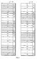
- FIG. 4shows a pair of cache memories having slots and control data associated therewith according to the system described herein.
- FIG. 5is a flow chart illustrating steps performed in connection with failure of the hardware associated with one of the pair of cache memories.
- FIG. 6is a flow chart illustrating steps performed in connection with a host accessing data in the cache memories.
- FIG. 7Ais a flow chart illustrating steps performed in connection with providing data from the disk storage area to the cache memories according to the system described herein.
- FIG. 7Bis a flow chart illustrating steps performed in connection with handling data that is modified after the data has been read into the cache according to the system described herein.
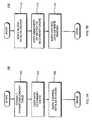
- FIG. 8is a flow chart illustrating steps performed in connection with recovery after failure and replacement of the hardware associated with one of the cache memories.
- a schematic diagram 20shows a first cache memory 22 , and a second cache memory 24 each coupled to a first bus 26 and a second bus 28 .
- the cache memories 22 , 24 and the buses 26 , 28may be part of a larger system, such as a data storage device provided by EMC Corporation of Hopkinton, Mass. Data may be written to and read from the memories 22 , 24 via the busses 26 , 28 .
- the first memory 22may be coupled to the first bus 26 via a first controller 32 and may be coupled to the second bus 28 via a second controller 34 .
- the second memory 24may be coupled to the first bus 26 via a third controller 36 and may be coupled to the second bus via a fourth controller 38 .
- the busses 26 , 28may be deemed “odd” and “even” for reference purposes.
- the memories 22 , 24may be deemed “top” and “bottom”.
- the buses 26 , 28are entirely redundant and each of the buses 26 , 28 is coupled to all of the disk controllers (not shown) and host interface units (not shown) of the corresponding storage device.
- each of the buses 26 , 28may be connected to a different set of host interface units and disk controllers, possibly with some overlap.
- Configuring and managing the redundancy of the buses 26 , 28may be provided according to a variety of functional factors known to one of ordinary skill in the art, and the system described herein is adaptable to any such configuration. Note that it is possible to further subdivide the busses 26 , 28 and the components connected thereto to reduce the likelihood of bringing the whole system down in connection with failure of a bus or of a component thereof.
- a schematic diagram 30shows an alternative embodiment where the first cache memory 22 and the second cache memory 24 are both coupled to a single bus 26 ′.
- the bus 26 ′may be coupled to all of the host interface units and all of the disk controllers of the corresponding storage device.
- the system described hereinmay be configured with either the embodiment of FIG. 1A, the embodiment of FIG. 1B, or other configurations of one or more buses coupled to the cache memories 22 , 24 .
- a schematic diagram 40illustrates a storage system 41 and the flow of data between the cache memories 22 , 24 , a disk storage area 42 , and a host system 44 .
- Dataflows between the first cache memory 22 and the disk storage area 42 and flows between the first cache memory 22 and the host system 44 .
- dataflows between the second cache memory 24 and the disk storage area 42 and between the second cache memory 24 and the host system 44 .
- Specific control of the data between the hosts system 44 , the cache memories 22 , 24 , and the disk storage areais described elsewhere herein.
- a table 52which is part of the data that is used to control operation of the storage device 41 , indicates portions T 1 , T 2 . . . TN of the cache memories 22 , 24 that are to be designated as primary storage areas.
- the cache memories 22 , 24are mapped alternatively so that, for example, a first set of portions may be designated as primary for the cache memory 22 while a second set of portions may be designated as primary for the cache memory 24 , where the first and second sets are interposed.
- the portionsare 1/4 Gigabyte in size, although it will be apparent to one of ordinary skill in the art that the invention may be practiced using other sizes. The purpose of the mapping is discussed in more detail elsewhere herein.
- each of the cache memories 22 , 24is implemented using separate hardware.
- Each of the memories 22 , 24is shown as containing a plurality of slots S 1 , S 2 , . . . SZ which, for embodiments discussed herein, provide storage for a sector of the disk storage area 42 .
- one sectorequals eight blocks and one block equals five hundred and twelve bytes.
- each of the slotsmay be specific control data elements C 1 , C 2 , . . . CZ, so that control data element C 1 is associated with slot S 1 , control data element C 2 is associated with slot S 2 , and so forth.
- control data element C 1is associated with slot S 1
- control data element C 2is associated with slot S 2
- the discussion hereinwill emphasize control data and the write pending state for sectors.
- Each of the slotsrepresents data that is read from the disk storage area 42 and stored in one or both of the cache memories 22 , 24 .
- the control data for each of the slotsindicates the state of the data in the slot.
- the control data element for a slotcan indicate that the data has been read from the disk storage area 42 but not written to by the host 44 (i.e., not modified by the host 44 ).
- the control data element for a slotcould indicate that the data in the slot has been written to by the host 44 since being read from the disk storage area 42 (i.e., write pending).
- data that is read from the disk storage area 42 but not subsequently modifiedmay be eliminated from the cache without any ultimate loss of data since the data in the memories 22 , 24 is the same as the data in the disk storage area 42 .
- data that is write pendingi.e., modified while in the memories 22 , 24 after being read from the disk storage area 42
- the control datacould indicate that the associated slot contains data that is the same in both of the memories 22 , 24 , which could occur, for example, either when the data is write pending or immediately after data that is write pending si written to the disk.
- data that is read from the disk storage area 42is written to one or the other of the memories 22 , 24 .
- the shading of the slots in the memories 22 , 24 in FIG. 4indicates that a slot has been designated as a secondary slot.
- the slots S 1 , S 2 . . . SN of the cache memory 22are designated as secondary slots while the slots SO, SP, . . . SQ of the cache memory 24 are designated as secondary slots.
- the slots SO, SP, . . . SQ of the cache memory 22are designated as primary slots while the slots S 1 , S 2 , . . . SN of the cache memory 24 are designated as primary slots.
- data that is read from the disk storage area 42is written only to the corresponding primary slot and, at least initially, is not written to the secondary slot.
- the datais read from the disk and is initially written only to the cache memory 24 .
- data from the disk designated for slot SPis initially written only to the cache memory 22 .
- the hardwaremay be used, in a conventional manner, to control writing to one of the cache memories 22 , 24 or writing to both of the memories 22 , 24 simultaneously (and/or with a single command). Similarly, the hardware may control which of the memories 22 , 24 is read.
- the modified datais written to both the primary memory and to the secondary memory.
- data that is designated for slot S 1is initially written from the disk storage area 42 only to the cache memory 24 .
- a subsequent operationoccurs that causes the data in slot S 1 to change (i.e., a write by the host 44 to the portion of the disk storage area 42 corresponding to slot S 1 )
- the data in slot S 1is modified according to the write operation which writes data to both of the memories 22 , 24 .
- data that is write pendingexists in both of the cache memories 22 , 24 .
- unmodified but related data in a slotmay be copied from one of the memories 22 , 24 to the other one of the memories 22 , 24 .
- the state of the data in the slotsis indicated by the control data.
- the corresponding control data elementindicates that the data has not been modified while, in the case of data that has been modified, the corresponding control data element indicates that the data is write pending.
- the control data for the slotsis written to both of the cache memories 22 , 24 .
- the entirety of the control datawill exist in the non-failing one of the cache memories 22 , 24 .
- the control data information in one of the cache memories 22 , 24is identical to the control data information in the other one of the cache memories 22 , 24 .
- any data that is write pending in the cacheis provided in both of the cache memories 22 , 24 .
- data that does not need to be written back to the disksi.e., data that has not been modified by the host 44
- Storing the data in only one of the cache memories 22 , 24is an optimization that can increase performance by requiring only one write to one of the cache memories 22 , 24 in certain instances, while providing a mechanism where write pending cache data is written to both of the cache memories 22 , 24 .
- identical datamay be stored in corresponding slots in both of the memories 22 , 24 even though the data is not write pending. This may occur, for example, immediately after write pending data is copied to the disk.
- a flow chart 60illustrates steps performed in the event that the hardware associated with one of the cache memories 22 , 24 fails.
- Implementing each of the cache memories 22 , 24 with separate hardwareincreases the likelihood that failure of the hardware for one of the cache memories 22 , 24 will not occur at the same time as failure of the hardware for an other one of the cache memories 22 , 24 .
- Detection of the failure of one of the cache memories 22 , 24is provided in a straightforward manner, such as described in U.S. Pat. No. 5,742,501 to Dewey et al., which is incorporated by reference herein. Note that detection of a failure may occur during an initial self test.
- Processingbegins at a first step 62 where a pointer is set to point to the first slot of the good cache memory (i.e., the one of the cache memories 22 , 24 that has not failed).
- a test step 64it is determined if the data stored in the slot that is pointed to is duplicated in the memories (i.e., is the same for both of the memories 22 , 24 ). As discussed above, this is indicated by the corresponding control data for the slot. Note that this information is available irrespective of whether the slot of the non-failing one of the cache memories 22 , 24 is a primary or a secondary storage area, since all of the control data is duplicated between the cache memories 22 , 24 , as discussed elsewhere herein.
- the non-failing cache memoryi.e., the one of the cache memories 22 , 24 that is being examined
- step 70where the next slot of the non-failing cache is pointed to in order to be examined on the next iteration.
- a test step 72where it is determined if processing is complete (i.e., no more slots remain to be examined). If it is determined at the test step 72 that there are more slots to examine, then control transfers back to the step 64 to process the next slot.
- step 70is also reached from the step 64 if it is determined that the data is the same in both of the memories 22 , 24 and that the step 70 is also is reached from the test step 66 if it is determined that the data, although not the same in both of the memories 22 , 24 , is stored in the non-failing one of the cache memories 22 , 24 . This is because, in either of these cases, it is not necessary to mark the control data for the slot being examined as indicating that the data is not in cache at the step 68 .
- a flow chart 80illustrates steps performed in connection with a read operation executed by the host where the data being read is in one or both of the cache memories 22 , 24 . Note that, if the hardware for one of the cache memories 22 , 24 fails, then only one of the cache memories 22 , 24 is used for all data read and write operations. However, in the course of normal operation, both of the cache memories 22 , 24 are used to store data.
- Processingbegins at a first step 82 where the control data for the data being accessed is obtained.
- the control datais duplicated between the cache memories 22 , 24 .
- the selection of one of the cache memories 22 , 24 from which to read the control data at the step 82may be random, or may be alternative (i.e., round robin), or may be some other scheme that may or may not provide for balancing accesses and/or performance enhancement between the cache memories 22 , 24 . In some embodiments, it may be desirable to provide load balancing and/or performance enhancement in connection with read operations.
- step 84it is determined if the data is the same in both of the memories 22 , 24 . As discussed above, this information may be provided by the corresponding control data element. If it is determined at the test step 84 that the data is the same in both of the memories 22 , 24 , then the data may be read from either one of the cache memories 22 , 24 . Thus, if it is determined at the step 84 that the data is the same in both of the cache memories 22 , 24 , then control passes from the step 84 to a step 86 , where the data is read from either of the cache memories 22 , 24 .
- the datais read from the one of the cache memories 22 , 24 that is used at the step 82 to obtain the control data. In other embodiments, at the step 86 the data is read from the one of the cache memories 22 , 24 opposite to the one of the cache memories 22 , 24 that is used at the step 82 . Following the step 86 , processing is complete.
- test step 84If it is determined at the test step 84 that the data that is not the same in both of the cache memories 22 , 24 , then control passes from the test step 84 to a test step 88 where the data is read from the primary cache for the data.
- the distinction between primary and secondary cache storageis discussed elsewhere herein. Following the step 88 , processing is complete.
- a flow chart 100illustrates steps performed in connection with providing data from the disk storage area 42 to the cache memories 22 , 24 .
- a first step 102it is determined which of the memories 22 , 24 is the primary storage area for the data.
- a step 104where the data is copied from the disk storage area 42 to the one of the memories 22 , 24 corresponding to the primary storage area.
- a step 106where the corresponding control data element, for both of the cache memories 22 , 24 , is marked to indicate that the corresponding data is in cache, thus indicating that the data has been read in to the cache.
- the control data for each of the slots of the cache memories 22 , 24is duplicated.
- control data element for any slot in one of the cache memories 22 , 24is made to equal the control data for the slot in the other one of the cache memories 22 , 24 by writing the control data to both of the memories 22 , 24 at the step 106 . Following the step 106 , processing is complete.
- a flow chart 110indicates steps performed in connection with the data in the cache that has been modified (e.g., by a write from the host 44 ). Note that the steps of the flow chart 110 may be executed some time after the data has been read from the disk storage area 41 in to the cache or may never be executed at all for some of the cache data.
- a block of data that is being modifiedis written to both of the cache memories 22 , 24 .
- the block of data that is being modifiedis written to both of the cache memories 22 , 24 .
- itis written to both of the caches 22 , 24 .
- the first time data from a slot (sector)is modified while in cache, other steps are also taken, as described below.
- a step 114where the remainder of the sector that includes the modified block is copied from the primary cache to the secondary cache.
- the embodiments disclosed hereinoperate a sector at a time, although is would be apparent to one of ordinary skill in the art how to adapt the system to operate using different size data increments, such as a block.
- the control datais provided on a per block basis, and if the cache holds and manipulates data in units of blocks, then it may be possible to forego the step 114 .
- the control dataindicates that the data for the sector is the same in both of the memories 22 , 24 , then the step 114 may be omitted, since there would be no need to copy data that is already the same.
- step 116the control data for the particular slot, in both of the memories 22 , 24 , is marked to indicate that the slot is write pending, indicating that the data has been modified while stored in the cache.
- the control datais written to both the primary and secondary storage areas.
- step 116processing is complete. Note that when the write pending data is destaged, the control data may indicate that the data is no longer write pending although the control data may also indicate that the sector data in both of the memories 22 , 24 is identical.
- the cache memories 22 , 24may be configured as separate memory boards (separate hardware) and, in some embodiments, may each have their own power supply. Using separate hardware for each of the cache memories 22 , 24 decreases the likelihood that both of the cache memories 22 , 24 will fail simultaneously. Thus, when the hardware for one of the cache memories 22 , 24 fails, the process set forth in FIG. 5, discussed above, may be executed to reconfigure the system to operate using a single cache memory.
- a flow chart 120illustrates steps performed after the hardware for one of the cache memories has failed. Processing begins at a first step 122 which determines if the failed memory hardware has been replaced. The test step 122 represents waiting until new, operational, hardware for the failed memory board is installed. Thus, until the hardware for the failed memory is replaced, the step 122 loops back on itself. Stated differently, the remaining steps of the flowchart 120 are not performed unless and until the failed memory board is successfully replaced.
- step 126Background copying refers to copying data from the non-failing one of the cache memories 22 , 24 to the other one of the cache memories 22 , 24 that corresponds to the new memory hardware. Background copying occurs when the cache is otherwise not being used. Thus, the steps 124 , 126 cause the cache memories 22 , 24 to eventually become duplicates of each other.
- a test step 128determines if background copying is complete. If not, the step 128 loops back on itself to wait for completion. Otherwise, once background copying is complete, the cache memories 22 , 24 are duplicates of each other and control passes from the step 128 to a step 130 , where the system is reconfigured to operate in the usual manner as discussed above in connection with the FIG. 6, FIG. 7A, and FIG. 7 B. Thus, when the hardware for one of the cache memories 22 , 24 fails, the system operates with the single, non-failing cache memory. However, once the recovery process set forth in FIG. 8 is completed, then the system is reconfigured to have a primary and secondary cache and to operate in the usual manner, as discussed above.
Landscapes
- Engineering & Computer Science (AREA)
- Theoretical Computer Science (AREA)
- Physics & Mathematics (AREA)
- General Engineering & Computer Science (AREA)
- General Physics & Mathematics (AREA)
- Quality & Reliability (AREA)
- Memory System Of A Hierarchy Structure (AREA)
Abstract
Description
Claims (35)
Priority Applications (2)
| Application Number | Priority Date | Filing Date | Title |
|---|---|---|---|
| US09/676,686US6591335B1 (en) | 2000-09-29 | 2000-09-29 | Fault tolerant dual cache system |
| US09/824,083US6961818B1 (en) | 2000-09-29 | 2001-04-02 | Method, system and computer program product for managing data in a mirrored cache using an access balancing technique |
Applications Claiming Priority (1)
| Application Number | Priority Date | Filing Date | Title |
|---|---|---|---|
| US09/676,686US6591335B1 (en) | 2000-09-29 | 2000-09-29 | Fault tolerant dual cache system |
Related Child Applications (1)
| Application Number | Title | Priority Date | Filing Date |
|---|---|---|---|
| US09/824,083Continuation-In-PartUS6961818B1 (en) | 2000-09-29 | 2001-04-02 | Method, system and computer program product for managing data in a mirrored cache using an access balancing technique |
Publications (1)
| Publication Number | Publication Date |
|---|---|
| US6591335B1true US6591335B1 (en) | 2003-07-08 |
Family
ID=24715538
Family Applications (2)
| Application Number | Title | Priority Date | Filing Date |
|---|---|---|---|
| US09/676,686Expired - LifetimeUS6591335B1 (en) | 2000-09-29 | 2000-09-29 | Fault tolerant dual cache system |
| US09/824,083Expired - LifetimeUS6961818B1 (en) | 2000-09-29 | 2001-04-02 | Method, system and computer program product for managing data in a mirrored cache using an access balancing technique |
Family Applications After (1)
| Application Number | Title | Priority Date | Filing Date |
|---|---|---|---|
| US09/824,083Expired - LifetimeUS6961818B1 (en) | 2000-09-29 | 2001-04-02 | Method, system and computer program product for managing data in a mirrored cache using an access balancing technique |
Country Status (1)
| Country | Link |
|---|---|
| US (2) | US6591335B1 (en) |
Cited By (23)
| Publication number | Priority date | Publication date | Assignee | Title |
|---|---|---|---|---|
| US20030120862A1 (en)* | 2001-12-20 | 2003-06-26 | Hitachi, Ltd. | Controlling method of storage apparatus, and storage apparatus, disk array device, and disk controller used in the method thereof |
| US20030204671A1 (en)* | 2002-04-26 | 2003-10-30 | Hitachi, Ltd. | Storage system |
| US20050015554A1 (en)* | 2003-07-15 | 2005-01-20 | Ofir Zohar | Self healing memory |
| US6961818B1 (en)* | 2000-09-29 | 2005-11-01 | Emc Corporation | Method, system and computer program product for managing data in a mirrored cache using an access balancing technique |
| EP1691293A1 (en)* | 2005-02-15 | 2006-08-16 | Hitachi, Ltd. | Storage system |
| US20070113006A1 (en)* | 2005-11-16 | 2007-05-17 | Elliott John C | Apparatus and method to configure one or more storage arrays |
| US20080250210A1 (en)* | 2007-04-03 | 2008-10-09 | International Business Machines Corporation | Copying data from a first cluster to a second cluster to reassign storage areas from the first cluster to the second cluster |
| US7941695B2 (en) | 2003-08-14 | 2011-05-10 | Compellent Technolgoies | Virtual disk drive system and method |
| US8468292B2 (en) | 2009-07-13 | 2013-06-18 | Compellent Technologies | Solid state drive data storage system and method |
| US8850114B2 (en) | 2010-09-07 | 2014-09-30 | Daniel L Rosenband | Storage array controller for flash-based storage devices |
| US20150199244A1 (en)* | 2014-01-15 | 2015-07-16 | Lsi Corporation | Intelligent i/o cache rebuild in a storage controller |
| US9146851B2 (en) | 2012-03-26 | 2015-09-29 | Compellent Technologies | Single-level cell and multi-level cell hybrid solid state drive |
| US20160019145A1 (en)* | 2013-10-15 | 2016-01-21 | Hitachi, Ltd. | Storage system and cache control method |
| US9489150B2 (en) | 2003-08-14 | 2016-11-08 | Dell International L.L.C. | System and method for transferring data between different raid data storage types for current data and replay data |
| US9575692B2 (en) | 2014-04-23 | 2017-02-21 | Electronics And Telecommunications Research Institute | Cache control device having fault-tolerant function and method of operating the same |
| US9830218B2 (en) | 2014-10-20 | 2017-11-28 | Electronics And Telecommunications Research Institute | Cache memory with fault tolerance |
| US10013310B2 (en) | 2016-03-02 | 2018-07-03 | Electronics And Telecommunications Research Institute | Cache memory device and operating method thereof |
| US10642782B2 (en) | 2016-12-08 | 2020-05-05 | Electronics And Telecommunications Research Institute | Multi-core processor and operation method thereof |
| US10740167B2 (en) | 2016-12-07 | 2020-08-11 | Electronics And Telecommunications Research Institute | Multi-core processor and cache management method thereof |
| US10983878B2 (en) | 2018-11-27 | 2021-04-20 | Electronics And Telecommunications Research Institute | Processor for detecting and preventing recognition error |
| US11036595B2 (en) | 2017-10-11 | 2021-06-15 | Electronics And Telecommunications Research Institute | Semiconductor system including fault manager |
| US11176395B2 (en) | 2018-11-30 | 2021-11-16 | Electronics And Telecommunications Research Institute | Image recognition processor including functional safety processor core and operation method thereof |
| US11341066B2 (en) | 2019-12-12 | 2022-05-24 | Electronics And Telecommunications Research Institute | Cache for artificial intelligence processor |
Families Citing this family (3)
| Publication number | Priority date | Publication date | Assignee | Title |
|---|---|---|---|---|
| US7769951B2 (en)* | 2007-04-10 | 2010-08-03 | Yahoo! Inc. | Intelligent caching of user data for real time communications |
| US8615678B1 (en)* | 2008-06-30 | 2013-12-24 | Emc Corporation | Auto-adapting multi-tier cache |
| US9063862B2 (en)* | 2011-05-17 | 2015-06-23 | Sandisk Technologies Inc. | Expandable data cache |
Citations (14)
| Publication number | Priority date | Publication date | Assignee | Title |
|---|---|---|---|---|
| US5206939A (en) | 1990-09-24 | 1993-04-27 | Emc Corporation | System and method for disk mapping and data retrieval |
| US5319766A (en) | 1992-04-24 | 1994-06-07 | Digital Equipment Corporation | Duplicate tag store for a processor having primary and backup cache memories in a multiprocessor computer system |
| US5390186A (en) | 1989-11-22 | 1995-02-14 | Hitachi, Ltd. | Method of fault handling for a disk control unit with built-in cache |
| US5404500A (en)* | 1992-12-17 | 1995-04-04 | International Business Machines Corporation | Storage control system with improved system and technique for destaging data from nonvolatile memory |
| US5437022A (en) | 1992-12-17 | 1995-07-25 | International Business Machines Corporation | Storage controller having additional cache memory and a means for recovering from failure and reconfiguring a control unit thereof in response thereto |
| US5640530A (en) | 1992-12-17 | 1997-06-17 | International Business Machines Corporation | Use of configuration registers to control access to multiple caches and nonvolatile stores |
| US5724501A (en) | 1996-03-29 | 1998-03-03 | Emc Corporation | Quick recovery of write cache in a fault tolerant I/O system |
| US5771367A (en) | 1992-12-17 | 1998-06-23 | International Business Machines Corporation | Storage controller and method for improved failure recovery using cross-coupled cache memories and nonvolatile stores |
| US5778394A (en) | 1996-12-23 | 1998-07-07 | Emc Corporation | Space reclamation system and method for use in connection with tape logging system |
| US5845147A (en) | 1996-03-19 | 1998-12-01 | Emc Corporation | Single lock command for an I/O storage system that performs both locking and I/O data operation |
| US5857208A (en) | 1996-05-31 | 1999-01-05 | Emc Corporation | Method and apparatus for performing point in time backup operation in a computer system |
| US6073251A (en) | 1989-12-22 | 2000-06-06 | Compaq Computer Corporation | Fault-tolerant computer system with online recovery and reintegration of redundant components |
| US6073209A (en) | 1997-03-31 | 2000-06-06 | Ark Research Corporation | Data storage controller providing multiple hosts with access to multiple storage subsystems |
| US6078503A (en) | 1997-06-30 | 2000-06-20 | Emc Corporation | Partitionable cabinet |
Family Cites Families (6)
| Publication number | Priority date | Publication date | Assignee | Title |
|---|---|---|---|---|
| JP3239669B2 (en)* | 1995-02-20 | 2001-12-17 | 株式会社日立製作所 | Storage control device and control method thereof |
| US6112257A (en)* | 1997-09-24 | 2000-08-29 | Emc Corporation | Dynamic adjustment of mirror service policy for logical volumes in a disk drive system based on collected statistics |
| JP3809930B2 (en)* | 1998-12-25 | 2006-08-16 | 株式会社日立製作所 | Information processing device |
| US6502165B1 (en)* | 1999-12-03 | 2002-12-31 | International Business Machines Corporation | Balanced access to data volumes with redundant copies stored in data storage libraries |
| US6604171B1 (en)* | 2000-09-29 | 2003-08-05 | Emc Corporation | Managing a cache memory |
| US6591335B1 (en)* | 2000-09-29 | 2003-07-08 | Emc Corporation | Fault tolerant dual cache system |
- 2000
- 2000-09-29USUS09/676,686patent/US6591335B1/ennot_activeExpired - Lifetime
- 2001
- 2001-04-02USUS09/824,083patent/US6961818B1/ennot_activeExpired - Lifetime
Patent Citations (14)
| Publication number | Priority date | Publication date | Assignee | Title |
|---|---|---|---|---|
| US5390186A (en) | 1989-11-22 | 1995-02-14 | Hitachi, Ltd. | Method of fault handling for a disk control unit with built-in cache |
| US6073251A (en) | 1989-12-22 | 2000-06-06 | Compaq Computer Corporation | Fault-tolerant computer system with online recovery and reintegration of redundant components |
| US5206939A (en) | 1990-09-24 | 1993-04-27 | Emc Corporation | System and method for disk mapping and data retrieval |
| US5319766A (en) | 1992-04-24 | 1994-06-07 | Digital Equipment Corporation | Duplicate tag store for a processor having primary and backup cache memories in a multiprocessor computer system |
| US5404500A (en)* | 1992-12-17 | 1995-04-04 | International Business Machines Corporation | Storage control system with improved system and technique for destaging data from nonvolatile memory |
| US5437022A (en) | 1992-12-17 | 1995-07-25 | International Business Machines Corporation | Storage controller having additional cache memory and a means for recovering from failure and reconfiguring a control unit thereof in response thereto |
| US5640530A (en) | 1992-12-17 | 1997-06-17 | International Business Machines Corporation | Use of configuration registers to control access to multiple caches and nonvolatile stores |
| US5771367A (en) | 1992-12-17 | 1998-06-23 | International Business Machines Corporation | Storage controller and method for improved failure recovery using cross-coupled cache memories and nonvolatile stores |
| US5845147A (en) | 1996-03-19 | 1998-12-01 | Emc Corporation | Single lock command for an I/O storage system that performs both locking and I/O data operation |
| US5724501A (en) | 1996-03-29 | 1998-03-03 | Emc Corporation | Quick recovery of write cache in a fault tolerant I/O system |
| US5857208A (en) | 1996-05-31 | 1999-01-05 | Emc Corporation | Method and apparatus for performing point in time backup operation in a computer system |
| US5778394A (en) | 1996-12-23 | 1998-07-07 | Emc Corporation | Space reclamation system and method for use in connection with tape logging system |
| US6073209A (en) | 1997-03-31 | 2000-06-06 | Ark Research Corporation | Data storage controller providing multiple hosts with access to multiple storage subsystems |
| US6078503A (en) | 1997-06-30 | 2000-06-20 | Emc Corporation | Partitionable cabinet |
Non-Patent Citations (1)
| Title |
|---|
| Pierre Raymond and John Nguyen, "Hitachi Freedom Storage 7700E Turbo-charges DB2", 1998, pp. 1-6. |
Cited By (50)
| Publication number | Priority date | Publication date | Assignee | Title |
|---|---|---|---|---|
| US6961818B1 (en)* | 2000-09-29 | 2005-11-01 | Emc Corporation | Method, system and computer program product for managing data in a mirrored cache using an access balancing technique |
| US20030120862A1 (en)* | 2001-12-20 | 2003-06-26 | Hitachi, Ltd. | Controlling method of storage apparatus, and storage apparatus, disk array device, and disk controller used in the method thereof |
| US7231491B2 (en) | 2002-04-26 | 2007-06-12 | Hitachi, Ltd. | Storage system and method using interface control devices of different types |
| US7444468B2 (en) | 2002-04-26 | 2008-10-28 | Hitachi, Ltd. | Storage system and method using interface control devices of different types |
| US20050033915A1 (en)* | 2002-04-26 | 2005-02-10 | Hitachi, Ltd. | Storage system and method using interface control devices of different types |
| US6810462B2 (en)* | 2002-04-26 | 2004-10-26 | Hitachi, Ltd. | Storage system and method using interface control devices of different types |
| US20030204671A1 (en)* | 2002-04-26 | 2003-10-30 | Hitachi, Ltd. | Storage system |
| US20070094447A1 (en)* | 2002-04-26 | 2007-04-26 | Hitachi, Ltd. | Storage system and method using interface control devices of different types |
| US20050015554A1 (en)* | 2003-07-15 | 2005-01-20 | Ofir Zohar | Self healing memory |
| US7827353B2 (en) | 2003-07-15 | 2010-11-02 | International Business Machines Corporation | Self healing memory |
| US10067712B2 (en) | 2003-08-14 | 2018-09-04 | Dell International L.L.C. | Virtual disk drive system and method |
| US9489150B2 (en) | 2003-08-14 | 2016-11-08 | Dell International L.L.C. | System and method for transferring data between different raid data storage types for current data and replay data |
| US9047216B2 (en) | 2003-08-14 | 2015-06-02 | Compellent Technologies | Virtual disk drive system and method |
| US8473776B2 (en) | 2003-08-14 | 2013-06-25 | Compellent Technologies | Virtual disk drive system and method |
| US9021295B2 (en) | 2003-08-14 | 2015-04-28 | Compellent Technologies | Virtual disk drive system and method |
| US8560880B2 (en) | 2003-08-14 | 2013-10-15 | Compellent Technologies | Virtual disk drive system and method |
| US8555108B2 (en) | 2003-08-14 | 2013-10-08 | Compellent Technologies | Virtual disk drive system and method |
| US9436390B2 (en) | 2003-08-14 | 2016-09-06 | Dell International L.L.C. | Virtual disk drive system and method |
| US7941695B2 (en) | 2003-08-14 | 2011-05-10 | Compellent Technolgoies | Virtual disk drive system and method |
| US7945810B2 (en) | 2003-08-14 | 2011-05-17 | Compellent Technologies | Virtual disk drive system and method |
| US7962778B2 (en) | 2003-08-14 | 2011-06-14 | Compellent Technologies | Virtual disk drive system and method |
| US8020036B2 (en)* | 2003-08-14 | 2011-09-13 | Compellent Technologies | Virtual disk drive system and method |
| US8321721B2 (en) | 2003-08-14 | 2012-11-27 | Compellent Technologies | Virtual disk drive system and method |
| US20080244183A1 (en)* | 2005-02-15 | 2008-10-02 | Atushi Ishikawa | Storage system |
| EP1691293A1 (en)* | 2005-02-15 | 2006-08-16 | Hitachi, Ltd. | Storage system |
| US20060184740A1 (en)* | 2005-02-15 | 2006-08-17 | Atushi Ishikawa | Storage system |
| CN100442250C (en)* | 2005-02-15 | 2008-12-10 | 株式会社日立制作所 | Storage system |
| US8612716B2 (en) | 2005-02-15 | 2013-12-17 | Hitachi, Ltd. | Storage system having partition size set in accordance with drive type |
| US7447843B2 (en)* | 2005-02-15 | 2008-11-04 | Hitachi, Ltd. | Storage system with independently adjustable cache memory partitions |
| US8832380B2 (en) | 2005-02-15 | 2014-09-09 | Hitachi, Ltd. | Storage system having cache partition size set based on drive type |
| US20070113006A1 (en)* | 2005-11-16 | 2007-05-17 | Elliott John C | Apparatus and method to configure one or more storage arrays |
| US20080250210A1 (en)* | 2007-04-03 | 2008-10-09 | International Business Machines Corporation | Copying data from a first cluster to a second cluster to reassign storage areas from the first cluster to the second cluster |
| US7761680B2 (en) | 2007-04-03 | 2010-07-20 | International Business Machines Corporation | Copying data from a first cluster to a second cluster to reassign storage areas from the first cluster to the second cluster |
| US8819334B2 (en) | 2009-07-13 | 2014-08-26 | Compellent Technologies | Solid state drive data storage system and method |
| US8468292B2 (en) | 2009-07-13 | 2013-06-18 | Compellent Technologies | Solid state drive data storage system and method |
| US8850114B2 (en) | 2010-09-07 | 2014-09-30 | Daniel L Rosenband | Storage array controller for flash-based storage devices |
| US9146851B2 (en) | 2012-03-26 | 2015-09-29 | Compellent Technologies | Single-level cell and multi-level cell hybrid solid state drive |
| US20160019145A1 (en)* | 2013-10-15 | 2016-01-21 | Hitachi, Ltd. | Storage system and cache control method |
| US9798661B2 (en)* | 2013-10-15 | 2017-10-24 | Hitachi, Ltd. | Storage system and cache control method |
| US9141486B2 (en)* | 2014-01-15 | 2015-09-22 | Avago Technologies General Ip (Singapore) Pte Ltd | Intelligent I/O cache rebuild in a storage controller |
| US20150199244A1 (en)* | 2014-01-15 | 2015-07-16 | Lsi Corporation | Intelligent i/o cache rebuild in a storage controller |
| US9575692B2 (en) | 2014-04-23 | 2017-02-21 | Electronics And Telecommunications Research Institute | Cache control device having fault-tolerant function and method of operating the same |
| US9830218B2 (en) | 2014-10-20 | 2017-11-28 | Electronics And Telecommunications Research Institute | Cache memory with fault tolerance |
| US10013310B2 (en) | 2016-03-02 | 2018-07-03 | Electronics And Telecommunications Research Institute | Cache memory device and operating method thereof |
| US10740167B2 (en) | 2016-12-07 | 2020-08-11 | Electronics And Telecommunications Research Institute | Multi-core processor and cache management method thereof |
| US10642782B2 (en) | 2016-12-08 | 2020-05-05 | Electronics And Telecommunications Research Institute | Multi-core processor and operation method thereof |
| US11036595B2 (en) | 2017-10-11 | 2021-06-15 | Electronics And Telecommunications Research Institute | Semiconductor system including fault manager |
| US10983878B2 (en) | 2018-11-27 | 2021-04-20 | Electronics And Telecommunications Research Institute | Processor for detecting and preventing recognition error |
| US11176395B2 (en) | 2018-11-30 | 2021-11-16 | Electronics And Telecommunications Research Institute | Image recognition processor including functional safety processor core and operation method thereof |
| US11341066B2 (en) | 2019-12-12 | 2022-05-24 | Electronics And Telecommunications Research Institute | Cache for artificial intelligence processor |
Also Published As
| Publication number | Publication date |
|---|---|
| US6961818B1 (en) | 2005-11-01 |
Similar Documents
| Publication | Publication Date | Title |
|---|---|---|
| US6604171B1 (en) | Managing a cache memory | |
| US6591335B1 (en) | Fault tolerant dual cache system | |
| US6049890A (en) | Disk array system and its control method | |
| US7600152B2 (en) | Configuring cache memory from a storage controller | |
| US5586291A (en) | Disk controller with volatile and non-volatile cache memories | |
| US5640530A (en) | Use of configuration registers to control access to multiple caches and nonvolatile stores | |
| US6006342A (en) | Failover and failback system for a direct access storage device | |
| US5051887A (en) | Maintaining duplex-paired storage devices during gap processing using of a dual copy function | |
| US7185222B2 (en) | Apparatus, system, and method for maintaining data in a storage array | |
| JP4821448B2 (en) | RAID controller and RAID device | |
| US20040019821A1 (en) | Method and apparatus for reliable failover involving incomplete raid disk writes in a clustering system | |
| JPH10105467A (en) | Method and device for keeping consistency of cache in raid controller provided with redundant cache | |
| JPH07230362A (en) | Disk array device | |
| US20210278989A1 (en) | Storage system and control method thereof | |
| US7293138B1 (en) | Method and apparatus for raid on memory | |
| JP2000181887A5 (en) | ||
| JP2002049511A (en) | Address allocation change method and external storage subsystem using the same | |
| US6611897B2 (en) | Method and apparatus for implementing redundancy on data stored in a disk array subsystem based on use frequency or importance of the data | |
| EP0303856B1 (en) | Method and apparatus for maintaining duplex-paired devices by means of a dual copy function | |
| JP2004213470A (en) | Disk array device, and data writing method for disk array device | |
| JPH06230903A (en) | Disk array device failure recovery method and disk array device | |
| JP4398596B2 (en) | Disk array device | |
| US7529776B2 (en) | Multiple copy track stage recovery in a data storage system | |
| JP3256329B2 (en) | Disk array device and control method therefor | |
| JP5729043B2 (en) | Storage device and control device |
Legal Events
| Date | Code | Title | Description |
|---|---|---|---|
| AS | Assignment | Owner name:EMC CORPORATION, MASSACHUSETTS Free format text:ASSIGNMENT OF ASSIGNORS INTEREST;ASSIGNORS:SADE, GILAD;SHAGAM, ELI;VISHLITZKY, NATAN;REEL/FRAME:011370/0897 Effective date:20001018 | |
| STCF | Information on status: patent grant | Free format text:PATENTED CASE | |
| FPAY | Fee payment | Year of fee payment:4 | |
| FEPP | Fee payment procedure | Free format text:PAYOR NUMBER ASSIGNED (ORIGINAL EVENT CODE: ASPN); ENTITY STATUS OF PATENT OWNER: LARGE ENTITY | |
| FPAY | Fee payment | Year of fee payment:8 | |
| FPAY | Fee payment | Year of fee payment:12 | |
| AS | Assignment | Owner name:CREDIT SUISSE AG, CAYMAN ISLANDS BRANCH, AS COLLATERAL AGENT, NORTH CAROLINA Free format text:SECURITY AGREEMENT;ASSIGNORS:ASAP SOFTWARE EXPRESS, INC.;AVENTAIL LLC;CREDANT TECHNOLOGIES, INC.;AND OTHERS;REEL/FRAME:040134/0001 Effective date:20160907 Owner name:THE BANK OF NEW YORK MELLON TRUST COMPANY, N.A., AS NOTES COLLATERAL AGENT, TEXAS Free format text:SECURITY AGREEMENT;ASSIGNORS:ASAP SOFTWARE EXPRESS, INC.;AVENTAIL LLC;CREDANT TECHNOLOGIES, INC.;AND OTHERS;REEL/FRAME:040136/0001 Effective date:20160907 Owner name:CREDIT SUISSE AG, CAYMAN ISLANDS BRANCH, AS COLLAT Free format text:SECURITY AGREEMENT;ASSIGNORS:ASAP SOFTWARE EXPRESS, INC.;AVENTAIL LLC;CREDANT TECHNOLOGIES, INC.;AND OTHERS;REEL/FRAME:040134/0001 Effective date:20160907 Owner name:THE BANK OF NEW YORK MELLON TRUST COMPANY, N.A., A Free format text:SECURITY AGREEMENT;ASSIGNORS:ASAP SOFTWARE EXPRESS, INC.;AVENTAIL LLC;CREDANT TECHNOLOGIES, INC.;AND OTHERS;REEL/FRAME:040136/0001 Effective date:20160907 | |
| AS | Assignment | Owner name:EMC IP HOLDING COMPANY LLC, MASSACHUSETTS Free format text:ASSIGNMENT OF ASSIGNORS INTEREST;ASSIGNOR:EMC CORPORATION;REEL/FRAME:040203/0001 Effective date:20160906 | |
| AS | Assignment | Owner name:THE BANK OF NEW YORK MELLON TRUST COMPANY, N.A., T Free format text:SECURITY AGREEMENT;ASSIGNORS:CREDANT TECHNOLOGIES, INC.;DELL INTERNATIONAL L.L.C.;DELL MARKETING L.P.;AND OTHERS;REEL/FRAME:049452/0223 Effective date:20190320 Owner name:THE BANK OF NEW YORK MELLON TRUST COMPANY, N.A., TEXAS Free format text:SECURITY AGREEMENT;ASSIGNORS:CREDANT TECHNOLOGIES, INC.;DELL INTERNATIONAL L.L.C.;DELL MARKETING L.P.;AND OTHERS;REEL/FRAME:049452/0223 Effective date:20190320 | |
| AS | Assignment | Owner name:THE BANK OF NEW YORK MELLON TRUST COMPANY, N.A., TEXAS Free format text:SECURITY AGREEMENT;ASSIGNORS:CREDANT TECHNOLOGIES INC.;DELL INTERNATIONAL L.L.C.;DELL MARKETING L.P.;AND OTHERS;REEL/FRAME:053546/0001 Effective date:20200409 | |
| AS | Assignment | Owner name:WYSE TECHNOLOGY L.L.C., CALIFORNIA Free format text:RELEASE BY SECURED PARTY;ASSIGNOR:CREDIT SUISSE AG, CAYMAN ISLANDS BRANCH;REEL/FRAME:058216/0001 Effective date:20211101 Owner name:SCALEIO LLC, MASSACHUSETTS Free format text:RELEASE BY SECURED PARTY;ASSIGNOR:CREDIT SUISSE AG, CAYMAN ISLANDS BRANCH;REEL/FRAME:058216/0001 Effective date:20211101 Owner name:MOZY, INC., WASHINGTON Free format text:RELEASE BY SECURED PARTY;ASSIGNOR:CREDIT SUISSE AG, CAYMAN ISLANDS BRANCH;REEL/FRAME:058216/0001 Effective date:20211101 Owner name:MAGINATICS LLC, CALIFORNIA Free format text:RELEASE BY SECURED PARTY;ASSIGNOR:CREDIT SUISSE AG, CAYMAN ISLANDS BRANCH;REEL/FRAME:058216/0001 Effective date:20211101 Owner name:FORCE10 NETWORKS, INC., CALIFORNIA Free format text:RELEASE BY SECURED PARTY;ASSIGNOR:CREDIT SUISSE AG, CAYMAN ISLANDS BRANCH;REEL/FRAME:058216/0001 Effective date:20211101 Owner name:EMC IP HOLDING COMPANY LLC, TEXAS Free format text:RELEASE BY SECURED PARTY;ASSIGNOR:CREDIT SUISSE AG, CAYMAN ISLANDS BRANCH;REEL/FRAME:058216/0001 Effective date:20211101 Owner name:EMC CORPORATION, MASSACHUSETTS Free format text:RELEASE BY SECURED PARTY;ASSIGNOR:CREDIT SUISSE AG, CAYMAN ISLANDS BRANCH;REEL/FRAME:058216/0001 Effective date:20211101 Owner name:DELL SYSTEMS CORPORATION, TEXAS Free format text:RELEASE BY SECURED PARTY;ASSIGNOR:CREDIT SUISSE AG, CAYMAN ISLANDS BRANCH;REEL/FRAME:058216/0001 Effective date:20211101 Owner name:DELL SOFTWARE INC., CALIFORNIA Free format text:RELEASE BY SECURED PARTY;ASSIGNOR:CREDIT SUISSE AG, CAYMAN ISLANDS BRANCH;REEL/FRAME:058216/0001 Effective date:20211101 Owner name:DELL PRODUCTS L.P., TEXAS Free format text:RELEASE BY SECURED PARTY;ASSIGNOR:CREDIT SUISSE AG, CAYMAN ISLANDS BRANCH;REEL/FRAME:058216/0001 Effective date:20211101 Owner name:DELL MARKETING L.P., TEXAS Free format text:RELEASE BY SECURED PARTY;ASSIGNOR:CREDIT SUISSE AG, CAYMAN ISLANDS BRANCH;REEL/FRAME:058216/0001 Effective date:20211101 Owner name:DELL INTERNATIONAL, L.L.C., TEXAS Free format text:RELEASE BY SECURED PARTY;ASSIGNOR:CREDIT SUISSE AG, CAYMAN ISLANDS BRANCH;REEL/FRAME:058216/0001 Effective date:20211101 Owner name:DELL USA L.P., TEXAS Free format text:RELEASE BY SECURED PARTY;ASSIGNOR:CREDIT SUISSE AG, CAYMAN ISLANDS BRANCH;REEL/FRAME:058216/0001 Effective date:20211101 Owner name:CREDANT TECHNOLOGIES, INC., TEXAS Free format text:RELEASE BY SECURED PARTY;ASSIGNOR:CREDIT SUISSE AG, CAYMAN ISLANDS BRANCH;REEL/FRAME:058216/0001 Effective date:20211101 Owner name:AVENTAIL LLC, CALIFORNIA Free format text:RELEASE BY SECURED PARTY;ASSIGNOR:CREDIT SUISSE AG, CAYMAN ISLANDS BRANCH;REEL/FRAME:058216/0001 Effective date:20211101 Owner name:ASAP SOFTWARE EXPRESS, INC., ILLINOIS Free format text:RELEASE BY SECURED PARTY;ASSIGNOR:CREDIT SUISSE AG, CAYMAN ISLANDS BRANCH;REEL/FRAME:058216/0001 Effective date:20211101 | |
| AS | Assignment | Owner name:SCALEIO LLC, MASSACHUSETTS Free format text:RELEASE OF SECURITY INTEREST IN PATENTS PREVIOUSLY RECORDED AT REEL/FRAME (040136/0001);ASSIGNOR:THE BANK OF NEW YORK MELLON TRUST COMPANY, N.A., AS NOTES COLLATERAL AGENT;REEL/FRAME:061324/0001 Effective date:20220329 Owner name:EMC IP HOLDING COMPANY LLC (ON BEHALF OF ITSELF AND AS SUCCESSOR-IN-INTEREST TO MOZY, INC.), TEXAS Free format text:RELEASE OF SECURITY INTEREST IN PATENTS PREVIOUSLY RECORDED AT REEL/FRAME (040136/0001);ASSIGNOR:THE BANK OF NEW YORK MELLON TRUST COMPANY, N.A., AS NOTES COLLATERAL AGENT;REEL/FRAME:061324/0001 Effective date:20220329 Owner name:EMC CORPORATION (ON BEHALF OF ITSELF AND AS SUCCESSOR-IN-INTEREST TO MAGINATICS LLC), MASSACHUSETTS Free format text:RELEASE OF SECURITY INTEREST IN PATENTS PREVIOUSLY RECORDED AT REEL/FRAME (040136/0001);ASSIGNOR:THE BANK OF NEW YORK MELLON TRUST COMPANY, N.A., AS NOTES COLLATERAL AGENT;REEL/FRAME:061324/0001 Effective date:20220329 Owner name:DELL MARKETING CORPORATION (SUCCESSOR-IN-INTEREST TO FORCE10 NETWORKS, INC. AND WYSE TECHNOLOGY L.L.C.), TEXAS Free format text:RELEASE OF SECURITY INTEREST IN PATENTS PREVIOUSLY RECORDED AT REEL/FRAME (040136/0001);ASSIGNOR:THE BANK OF NEW YORK MELLON TRUST COMPANY, N.A., AS NOTES COLLATERAL AGENT;REEL/FRAME:061324/0001 Effective date:20220329 Owner name:DELL PRODUCTS L.P., TEXAS Free format text:RELEASE OF SECURITY INTEREST IN PATENTS PREVIOUSLY RECORDED AT REEL/FRAME (040136/0001);ASSIGNOR:THE BANK OF NEW YORK MELLON TRUST COMPANY, N.A., AS NOTES COLLATERAL AGENT;REEL/FRAME:061324/0001 Effective date:20220329 Owner name:DELL INTERNATIONAL L.L.C., TEXAS Free format text:RELEASE OF SECURITY INTEREST IN PATENTS PREVIOUSLY RECORDED AT REEL/FRAME (040136/0001);ASSIGNOR:THE BANK OF NEW YORK MELLON TRUST COMPANY, N.A., AS NOTES COLLATERAL AGENT;REEL/FRAME:061324/0001 Effective date:20220329 Owner name:DELL USA L.P., TEXAS Free format text:RELEASE OF SECURITY INTEREST IN PATENTS PREVIOUSLY RECORDED AT REEL/FRAME (040136/0001);ASSIGNOR:THE BANK OF NEW YORK MELLON TRUST COMPANY, N.A., AS NOTES COLLATERAL AGENT;REEL/FRAME:061324/0001 Effective date:20220329 Owner name:DELL MARKETING L.P. (ON BEHALF OF ITSELF AND AS SUCCESSOR-IN-INTEREST TO CREDANT TECHNOLOGIES, INC.), TEXAS Free format text:RELEASE OF SECURITY INTEREST IN PATENTS PREVIOUSLY RECORDED AT REEL/FRAME (040136/0001);ASSIGNOR:THE BANK OF NEW YORK MELLON TRUST COMPANY, N.A., AS NOTES COLLATERAL AGENT;REEL/FRAME:061324/0001 Effective date:20220329 Owner name:DELL MARKETING CORPORATION (SUCCESSOR-IN-INTEREST TO ASAP SOFTWARE EXPRESS, INC.), TEXAS Free format text:RELEASE OF SECURITY INTEREST IN PATENTS PREVIOUSLY RECORDED AT REEL/FRAME (040136/0001);ASSIGNOR:THE BANK OF NEW YORK MELLON TRUST COMPANY, N.A., AS NOTES COLLATERAL AGENT;REEL/FRAME:061324/0001 Effective date:20220329 | |
| AS | Assignment | Owner name:SCALEIO LLC, MASSACHUSETTS Free format text:RELEASE OF SECURITY INTEREST IN PATENTS PREVIOUSLY RECORDED AT REEL/FRAME (045455/0001);ASSIGNOR:THE BANK OF NEW YORK MELLON TRUST COMPANY, N.A., AS NOTES COLLATERAL AGENT;REEL/FRAME:061753/0001 Effective date:20220329 Owner name:EMC IP HOLDING COMPANY LLC (ON BEHALF OF ITSELF AND AS SUCCESSOR-IN-INTEREST TO MOZY, INC.), TEXAS Free format text:RELEASE OF SECURITY INTEREST IN PATENTS PREVIOUSLY RECORDED AT REEL/FRAME (045455/0001);ASSIGNOR:THE BANK OF NEW YORK MELLON TRUST COMPANY, N.A., AS NOTES COLLATERAL AGENT;REEL/FRAME:061753/0001 Effective date:20220329 Owner name:EMC CORPORATION (ON BEHALF OF ITSELF AND AS SUCCESSOR-IN-INTEREST TO MAGINATICS LLC), MASSACHUSETTS Free format text:RELEASE OF SECURITY INTEREST IN PATENTS PREVIOUSLY RECORDED AT REEL/FRAME (045455/0001);ASSIGNOR:THE BANK OF NEW YORK MELLON TRUST COMPANY, N.A., AS NOTES COLLATERAL AGENT;REEL/FRAME:061753/0001 Effective date:20220329 Owner name:DELL MARKETING CORPORATION (SUCCESSOR-IN-INTEREST TO FORCE10 NETWORKS, INC. AND WYSE TECHNOLOGY L.L.C.), TEXAS Free format text:RELEASE OF SECURITY INTEREST IN PATENTS PREVIOUSLY RECORDED AT REEL/FRAME (045455/0001);ASSIGNOR:THE BANK OF NEW YORK MELLON TRUST COMPANY, N.A., AS NOTES COLLATERAL AGENT;REEL/FRAME:061753/0001 Effective date:20220329 Owner name:DELL PRODUCTS L.P., TEXAS Free format text:RELEASE OF SECURITY INTEREST IN PATENTS PREVIOUSLY RECORDED AT REEL/FRAME (045455/0001);ASSIGNOR:THE BANK OF NEW YORK MELLON TRUST COMPANY, N.A., AS NOTES COLLATERAL AGENT;REEL/FRAME:061753/0001 Effective date:20220329 Owner name:DELL INTERNATIONAL L.L.C., TEXAS Free format text:RELEASE OF SECURITY INTEREST IN PATENTS PREVIOUSLY RECORDED AT REEL/FRAME (045455/0001);ASSIGNOR:THE BANK OF NEW YORK MELLON TRUST COMPANY, N.A., AS NOTES COLLATERAL AGENT;REEL/FRAME:061753/0001 Effective date:20220329 Owner name:DELL USA L.P., TEXAS Free format text:RELEASE OF SECURITY INTEREST IN PATENTS PREVIOUSLY RECORDED AT REEL/FRAME (045455/0001);ASSIGNOR:THE BANK OF NEW YORK MELLON TRUST COMPANY, N.A., AS NOTES COLLATERAL AGENT;REEL/FRAME:061753/0001 Effective date:20220329 Owner name:DELL MARKETING L.P. (ON BEHALF OF ITSELF AND AS SUCCESSOR-IN-INTEREST TO CREDANT TECHNOLOGIES, INC.), TEXAS Free format text:RELEASE OF SECURITY INTEREST IN PATENTS PREVIOUSLY RECORDED AT REEL/FRAME (045455/0001);ASSIGNOR:THE BANK OF NEW YORK MELLON TRUST COMPANY, N.A., AS NOTES COLLATERAL AGENT;REEL/FRAME:061753/0001 Effective date:20220329 Owner name:DELL MARKETING CORPORATION (SUCCESSOR-IN-INTEREST TO ASAP SOFTWARE EXPRESS, INC.), TEXAS Free format text:RELEASE OF SECURITY INTEREST IN PATENTS PREVIOUSLY RECORDED AT REEL/FRAME (045455/0001);ASSIGNOR:THE BANK OF NEW YORK MELLON TRUST COMPANY, N.A., AS NOTES COLLATERAL AGENT;REEL/FRAME:061753/0001 Effective date:20220329 | |
| AS | Assignment | Owner name:DELL MARKETING L.P. (ON BEHALF OF ITSELF AND AS SUCCESSOR-IN-INTEREST TO CREDANT TECHNOLOGIES, INC.), TEXAS Free format text:RELEASE OF SECURITY INTEREST IN PATENTS PREVIOUSLY RECORDED AT REEL/FRAME (053546/0001);ASSIGNOR:THE BANK OF NEW YORK MELLON TRUST COMPANY, N.A., AS NOTES COLLATERAL AGENT;REEL/FRAME:071642/0001 Effective date:20220329 Owner name:DELL INTERNATIONAL L.L.C., TEXAS Free format text:RELEASE OF SECURITY INTEREST IN PATENTS PREVIOUSLY RECORDED AT REEL/FRAME (053546/0001);ASSIGNOR:THE BANK OF NEW YORK MELLON TRUST COMPANY, N.A., AS NOTES COLLATERAL AGENT;REEL/FRAME:071642/0001 Effective date:20220329 Owner name:DELL PRODUCTS L.P., TEXAS Free format text:RELEASE OF SECURITY INTEREST IN PATENTS PREVIOUSLY RECORDED AT REEL/FRAME (053546/0001);ASSIGNOR:THE BANK OF NEW YORK MELLON TRUST COMPANY, N.A., AS NOTES COLLATERAL AGENT;REEL/FRAME:071642/0001 Effective date:20220329 Owner name:DELL USA L.P., TEXAS Free format text:RELEASE OF SECURITY INTEREST IN PATENTS PREVIOUSLY RECORDED AT REEL/FRAME (053546/0001);ASSIGNOR:THE BANK OF NEW YORK MELLON TRUST COMPANY, N.A., AS NOTES COLLATERAL AGENT;REEL/FRAME:071642/0001 Effective date:20220329 Owner name:EMC CORPORATION, MASSACHUSETTS Free format text:RELEASE OF SECURITY INTEREST IN PATENTS PREVIOUSLY RECORDED AT REEL/FRAME (053546/0001);ASSIGNOR:THE BANK OF NEW YORK MELLON TRUST COMPANY, N.A., AS NOTES COLLATERAL AGENT;REEL/FRAME:071642/0001 Effective date:20220329 Owner name:DELL MARKETING CORPORATION (SUCCESSOR-IN-INTEREST TO FORCE10 NETWORKS, INC. AND WYSE TECHNOLOGY L.L.C.), TEXAS Free format text:RELEASE OF SECURITY INTEREST IN PATENTS PREVIOUSLY RECORDED AT REEL/FRAME (053546/0001);ASSIGNOR:THE BANK OF NEW YORK MELLON TRUST COMPANY, N.A., AS NOTES COLLATERAL AGENT;REEL/FRAME:071642/0001 Effective date:20220329 Owner name:EMC IP HOLDING COMPANY LLC, TEXAS Free format text:RELEASE OF SECURITY INTEREST IN PATENTS PREVIOUSLY RECORDED AT REEL/FRAME (053546/0001);ASSIGNOR:THE BANK OF NEW YORK MELLON TRUST COMPANY, N.A., AS NOTES COLLATERAL AGENT;REEL/FRAME:071642/0001 Effective date:20220329 |