US6591106B1 - Transmission system for transmitting digital signals in a radio subscriber terminal network - Google Patents
Transmission system for transmitting digital signals in a radio subscriber terminal networkDownload PDFInfo
- Publication number
- US6591106B1 US6591106B1US09/200,360US20036098AUS6591106B1US 6591106 B1US6591106 B1US 6591106B1US 20036098 AUS20036098 AUS 20036098AUS 6591106 B1US6591106 B1US 6591106B1
- Authority
- US
- United States
- Prior art keywords
- base station
- radio
- transmitting
- transmitting power
- frequency sub
- Prior art date
- Legal status (The legal status is an assumption and is not a legal conclusion. Google has not performed a legal analysis and makes no representation as to the accuracy of the status listed.)
- Expired - Lifetime
Links
Images

Classifications
- H—ELECTRICITY
- H04—ELECTRIC COMMUNICATION TECHNIQUE
- H04W—WIRELESS COMMUNICATION NETWORKS
- H04W52/00—Power management, e.g. Transmission Power Control [TPC] or power classes
- H04W52/04—Transmission power control [TPC]
- H04W52/30—Transmission power control [TPC] using constraints in the total amount of available transmission power
- H04W52/34—TPC management, i.e. sharing limited amount of power among users or channels or data types, e.g. cell loading
- H04W52/346—TPC management, i.e. sharing limited amount of power among users or channels or data types, e.g. cell loading distributing total power among users or channels
- H—ELECTRICITY
- H04—ELECTRIC COMMUNICATION TECHNIQUE
- H04B—TRANSMISSION
- H04B7/00—Radio transmission systems, i.e. using radiation field
- H04B7/02—Diversity systems; Multi-antenna system, i.e. transmission or reception using multiple antennas
- H04B7/12—Frequency diversity
- H—ELECTRICITY
- H04—ELECTRIC COMMUNICATION TECHNIQUE
- H04B—TRANSMISSION
- H04B7/00—Radio transmission systems, i.e. using radiation field
- H04B7/24—Radio transmission systems, i.e. using radiation field for communication between two or more posts
- H04B7/26—Radio transmission systems, i.e. using radiation field for communication between two or more posts at least one of which is mobile
- H04B7/2615—Radio transmission systems, i.e. using radiation field for communication between two or more posts at least one of which is mobile using hybrid frequency-time division multiple access [FDMA-TDMA]
- H—ELECTRICITY
- H04—ELECTRIC COMMUNICATION TECHNIQUE
- H04W—WIRELESS COMMUNICATION NETWORKS
- H04W16/00—Network planning, e.g. coverage or traffic planning tools; Network deployment, e.g. resource partitioning or cells structures
Definitions
- a radio subscriber terminal networkis a system (typically covering an area) of radio cells which respectively contain a stationary base station (usually optimally centrally situated) about which the network terminations (NTs) of the radio subscriber are more or less evenly distributed in a radius of, for example, 1 km.
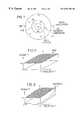
- a radio cellis sketched in FIG. 1, in which the base station is referenced BS and the radio subscribers (or respectively, their network terminations) are referenced NT. Since the radio field attenuation in a radio system increases quadratically with distance, the radio field strength at the cell margin is significantly less than in the cell interior; in FIG. 1 this attenuation is illustrated with concentric circles about the base station. Additional attenuations conditioned by rain, for example, which likewise depend on distance, can additionally sharply reduce the receiving power available in the network terminations at the cell margin.
- the signal transmission from the base station downstream to the radio subscriberscan proceed in time division multiplex (TDM) in a 155 Mbit/s bit stream, and the signal transmission from the radio subscribers upstream to the base station can proceed in a TDMA (Time Division Multiple Access) method.
- TDMtime division multiplex
- TDMATime Division Multiple Access
- All network terminationsprocess the full total bit rate of 155 Mbit/s of the downstream time division multiplex signal, although only a small part of this bit rate is usually assigned to the respective network termination specifically.
- the high bandwidth of the time division multiplex signal thereinleads to a correspondingly poor signal/noise power ratio at the subscriber-specific receiver.
- the transmitting power of the base stationBS in FIG. 1 is limited for reasons of telecommunications law and/or for technical reasons, the greatest possible cell radius therefore emerging from defined parameters such as RF transmitting frequency, total bit rate, directivity, and signal/noise ratio; in those network terminations (NT in FIG. 1) which are situated nearer to the base station, the reception power (and thus also the signal/noise power ratio) is greater than what is necessary for a prescribed bit error rate, so that transmitting power is “given away”.
- the uniform distribution of the total available power over time t and frequency fis illustrated by the “water-filling diagram” for a channel with a bandwith B, a period T and a transmitting power P s (FIG. 2 ).
- Such an even power distribution as that which is illustrated by the hatched flat surface of the diagram in FIG. 2is ideal in a radio system in which all network terminations have the same constant distance from the base station. Taking the period T as constant, so that it need not be depicted in the diagram, and introducing the distance r from the base station as the third variable, the shaded curved surface in FIG.
- FIG. 3is obtained for the transmitting power P needed for a constant bit error rate, this surface emerging in that for each point of the plane the required power P for a prescribed bit error rate (for example, 10 ⁇ 9 ) is plotted.
- Pis barely dependent on the frequency.
- FIG. 3the power distribution according to the “water-filling” algorithm (FIG. 2 ), that is given a power P s which is not dependent on distance r, is illustrated in hatched fashion. The distance between the curved and the straight surfaces is then a measure of the power termed “given away” given a defined distance r.
- the receiving power within a radio cellcan be respectively measured at the individual network terminations NT and used as a measure of the respective radio field attenuation, according to which the transmitting power of the relevant network termination is correspondingly readjusted.
- the individual network terminations NT of a radio cellcan be actuated in succession with adaptive antennas, the higher gain of such antennas compared to omnidirectional antennas permitting the bridging of correspondingly greater distances given the same transmitting power.
- Adaptive antennasare admittedly just at the beginning of development.
- Different modulation methodscan also be utilized for more remote network terminations, on the one hand, and for network terminations in the vicinity of the base station, on the other hand, for example, 16QAM for the inner region and QPSK for the outer region of the radio cell.
- the required signal/noise ratio (S/N)is smaller in QPSK than in 16QAM by 7 dB.
- S/Nsignal/noise ratio
- 16QAMthe linearity requirements are admittedly increased, specifically in the amplifiers.
- Such a methodis suitable primarily for OFDM.
- the inventionnow demonstrates another way to optimize the power distribution within a radio cell.
- the inventionrelates to a system for transmitting digital signals in a radio subscriber terminal network, particularly in a broad-band RLL (Radio in the Local Loop) subscriber terminal network; this transmission system is inventively characterized in that, for the digital signal transmission from the base station of a radio cell to the radio subscribers located in the radio cell, the total transmitting power of the base station is divided into a plurality of frequency sub-bands and/or periods with different transmitting powers, and the digital signals assigned to radio subscribers located a greater or lesser distance from the base station are transmitted in frequency sub-bands and/or periods with correspondingly higher, or respectively, lower transmitting power of the base station.
- RLLRadio in the Local Loop
- a fixed number of frequency sub-bands with respectively strictly prescribed transmitting power of the base stationcan be provided, from which one or more frequency sub-bands of the respectively required transmitting power are allocated to each connection from the base station to a radio subscriber, according to its distance from the base station.
- the transmitting power of the base stationcan also be modulated with one or more integral harmonics of a sinusoidal oscillation of a prescribed frequency, and a period of the required transmitting power can be allocated to each connection from the base station to a radio subscriber, according to its distance from the base station.
- the inventionadvantageously enables an optimal power distribution within the radio cell, it being possible either to reduce the total transmitting power of the base station, accordingly, or even to utilize the gained power to increase the cell radius, given a constant total transmitting power.
- the modulation of the transmitting power with one or more sinusoidal oscillations which are integral harmonics of a sinusoidal oscillation of a prescribed frequencyenables the specific allocation of phases of high, or respectively, low transmitting power to the individual connections between the base station and the more or less remote radio subscribers, according to the distance.
- a modulation of the transmitting poweris associated only with a negligible broadening of the RF spectrum.
- the transmitting powervaries by 24 dB.
- the powers of the frequency sub-bandsaccumulate geometrically; that is the total power is essentially located in the frequency sub-bands with the highest power. The range increase is correspondingly large.
- the signal transmission from the base station downstream to the radio subscriberscan in turn proceed in time division multiplex, potentially in each frequency sub-band separately; QPSK can be uniformly provided as modulation method for the data signals to be transmitted.
- QPSKcan be uniformly provided as modulation method for the data signals to be transmitted.
- the utilization of mutually orthogonal carriers for the individual frequency sub-bandsavoids the filtering losses which are otherwise unavoidable in FDMA (Frequency Division Multiple Access).
- FIG. 1depicts the typical image of a radio cell with attenuations which arise therein;
- FIG. 2depicts the even distribution of the available total transmitting power over the time and the frequency
- FIG. 3illustrates the characteristic of the transmitting power which is required for a constant bit error rate dependent on the distance of the radio subscriber from the transmitting base station;
- FIG. 4schematicaly depicts an exemplifying embodiment of a division of the total transmitting power of the base station (BS in FIG. 1) of a radio cell (FIG. 1) into frequency sub-bands FK 0 , FK 1 , . . . FKk of different transmitting powers, from which one or more of the frequency sub-bands of the respectively required transmitting power(s) are allocated to each connection from the base station to a radio subscriber, according to its distance from the base station, for the digital transmission from the base station to the radio subscribers (NT in FIG.
- the signals emitted by the base station BS (FIG. 1) with the individual frequency-sub-band-specific transmitting powersform an OFDM (Orthogonal Frequency Division Multiplex) signal with few carriers, the actual multiple access proceeding in time division multiplex (TDM).
- OFDMOrthogonal Frequency Division Multiplex
- TDMtime division multiplex
- the outlay for the OFDMremains low.
- the symbol durationis extended so much that a costly equalizer, which is otherwise necessary in TDM/TDMA due to what are known as multipath distortions, can be forgone.
- the crest factoris very unfavorable in itself, which carries disadvantages primarily in highly non-linear amplifiers.
- the powers of the frequency sub-bandsaccumulate geometrically, that is, the total power is essentially determined by the frequency sub-band with the greatest power.
- the crest factoris thus significantly more favorable than in OFDM with constant carrier amplitudes.
- the division of the total available frequency band into frequency sub-bands of varying base station transmitting poweralso permits an improvement of the frequency re-use.
- the common channel interference of frequency sub-bands with low transmitting poweris intrinsically very low.
- the common channel interference of the frequency sub-bands with higher poweris just as great as in the current systems, but it is now limited to a significantly smaller frequency range. Basically, the transmitting system keeps the interference power as low as possible.
- Frequency sub-bands with continuously controllable transmitting power of the base station, and not with respectively strictly prescribed transmitting power,can also be provided.
- Such a development of the transmitting systempermits an adaptive adjustment to the relations respectively prevailing in the radio cell (for example, an increase, conditioned by rain, of the radio field attenuation during the establishment of a connection; the number of active radio subscribers).
- the signals assigned to a network terminationcan also be divided into frequency sub-bands of varying power.
- the received bitsare then more or less reliable according to frequency sub-band, the less reliable bits being effectively corrected with the aid of a corresponding coding method.
- the frequency band FK 0 with the highest powercan also be utilized as emergency channel for all connections from the base station (BS in FIG. 1) to the network terminations of the radio subscriber (NT in FIG. 1 ), via which channel at least telephone traffic is still possible given sharply increased radio field attenuation, conditioned by heavy rain, for example.
- FIG. 5schematically illustrates a division of the total transmitting power of the base station (BS in FIG. 1) of a radio cell (FIG. 1) into periods ZK 0 , ZK 1 , . . . , ZKk of different transmitting powers, from which one or more periods of the respectively required transmitting power(s) is allocated to each connection from the base station to a radio subscriber, according to its distance from the base station, for the digital transmission from the base station to the radio subscribers (NT in FIG.
- the power modulation sketched in FIG. 5results from the superposition of the first and third harmonics of a sinusoidal oscillation (for example, of 10 kHz). In the receivers of the radio subscribers the power modulation can be cancelled out again with the aid of an opposite modulation.
- the signals assigned to a network terminationcan also be divided into periods of varying power.
- the received bitsare then more or less reliable, depending on the period, the less reliable bits being effectively corrected with the aid of a corresponding coding method.
- the period Z 0 with the highest powercan also be utilized as emergency channel for all the connections from the base station (BS in FIG. 1) to the network terminations of the radio subscriber (NT in FIG. 1 ), via which channel at least telephone traffic is still possible given sharply increased radio field attenuation, for example, conditioned by heavy rain.
- a power scaling in the frequency rangecan also be combined with a power scaling in the time range, as explained above with the aid of FIG. 5, without further explanation being necessary.
Landscapes
- Engineering & Computer Science (AREA)
- Computer Networks & Wireless Communication (AREA)
- Signal Processing (AREA)
- Mobile Radio Communication Systems (AREA)
Abstract
Description
Claims (18)
Applications Claiming Priority (2)
| Application Number | Priority Date | Filing Date | Title |
|---|---|---|---|
| DE19752200ADE19752200C1 (en) | 1997-11-25 | 1997-11-25 | Digital signal transmission system in radio subscriber connection network |
| DE19752200 | 1997-11-25 |
Publications (1)
| Publication Number | Publication Date |
|---|---|
| US6591106B1true US6591106B1 (en) | 2003-07-08 |
Family
ID=7849768
Family Applications (1)
| Application Number | Title | Priority Date | Filing Date |
|---|---|---|---|
| US09/200,360Expired - LifetimeUS6591106B1 (en) | 1997-11-25 | 1998-11-25 | Transmission system for transmitting digital signals in a radio subscriber terminal network |
Country Status (3)
| Country | Link |
|---|---|
| US (1) | US6591106B1 (en) |
| EP (1) | EP0920145A3 (en) |
| DE (1) | DE19752200C1 (en) |
Cited By (16)
| Publication number | Priority date | Publication date | Assignee | Title |
|---|---|---|---|---|
| US20040127175A1 (en)* | 2002-08-27 | 2004-07-01 | Nortel Networks Limited. | Method of transmitting radio signals with polarization diversity and radiocommunication station and terminal for implementing the method |
| US20050096061A1 (en)* | 2003-10-30 | 2005-05-05 | Qualcomm Incorporated | Layered reuse for a wireless communication system |
| US20050096062A1 (en)* | 2003-10-30 | 2005-05-05 | Ji Tingfang | Restrictive reuse for a wireless communication system |
| US20050170808A1 (en)* | 2004-01-29 | 2005-08-04 | Hamilton Gordon E. | Radio interoperability system |
| US20050281228A1 (en)* | 2004-06-22 | 2005-12-22 | Samsung Electronics Co., Ltd. | System for soft handover in MIMO OFDMA mobile communication system and method thereof |
| US20060002360A1 (en)* | 2004-06-09 | 2006-01-05 | Ji Tingfang | Dynamic restrictive reuse scheduler |
| US20060030281A1 (en)* | 2002-11-05 | 2006-02-09 | Roman Brunel | Method for transmit power compensation in a mobile communication terminal and communication terminal for implementing said method |
| US20060135169A1 (en)* | 2004-12-22 | 2006-06-22 | Qualcomm Incorporated | Feedback to support restrictive reuse |
| US20060252436A1 (en)* | 2005-05-06 | 2006-11-09 | Nokia Corporation | Interference control method, network element, device, computer program product and computer program distribution medium |
| WO2006120297A1 (en)* | 2005-05-06 | 2006-11-16 | Nokia Corporation | Interference control method, network element, device, computer program product and computer program distribution medium |
| US20070149125A1 (en)* | 2005-12-21 | 2007-06-28 | Duncan Bremner | Communication system and method |
| US20080212460A1 (en)* | 2007-03-02 | 2008-09-04 | Qualcomm Incorporated | Robust transmission scheme for wireless networks |
| US20090175224A1 (en)* | 2006-09-28 | 2009-07-09 | Mitsuhiro Ono | Wireless Base Station Which Operates In Degraded Mode In Mobile Communication System During Disaster, And Mobile Communication System |
| US7680475B2 (en) | 2004-06-09 | 2010-03-16 | Qualcomm Incorporated | Dynamic ASBR scheduler |
| US8032145B2 (en) | 2004-07-23 | 2011-10-04 | Qualcomm Incorporated | Restrictive reuse set management algorithm for equal grade of service on FL transmission |
| US8890744B1 (en) | 1999-04-07 | 2014-11-18 | James L. Geer | Method and apparatus for the detection of objects using electromagnetic wave attenuation patterns |
Families Citing this family (3)
| Publication number | Priority date | Publication date | Assignee | Title |
|---|---|---|---|---|
| DE10223994A1 (en)* | 2002-05-29 | 2003-10-16 | Siemens Ag | Method for controlling transmission output from a transmission station in a radio system allocates carriers with different frequencies to a connection. |
| GB2396522B (en) | 2002-12-18 | 2006-01-04 | Motorola Inc | Method and apparatus for determining a transmit power |
| US8433327B2 (en) | 2010-05-19 | 2013-04-30 | Alcatel Lucent | Methods of determining coverage areas |
Citations (35)
| Publication number | Priority date | Publication date | Assignee | Title |
|---|---|---|---|---|
| US4751728A (en)* | 1987-03-27 | 1988-06-14 | Treat John M | Telephone call monitoring, metering and selection device |
| US4956875A (en)* | 1988-07-05 | 1990-09-11 | Com-Ser Laboratories, Inc. | Emergency radio alerting and message transmitting system directable to selected classes and numbers of receivers |
| US5303297A (en)* | 1991-07-25 | 1994-04-12 | Motorola, Inc. | Dynamic pricing method and apparatus for communication systems |
| US5448751A (en)* | 1992-04-10 | 1995-09-05 | Fujitsu Limited | Method and apparatus for assigning radio channels in mobile communications systems |
| WO1996031014A1 (en) | 1995-03-31 | 1996-10-03 | Qualcomm Incorporated | Method and apparatus for performing power control in a mobile communication system |
| US5577100A (en)* | 1995-01-30 | 1996-11-19 | Telemac Cellular Corporation | Mobile phone with internal accounting |
| US5586338A (en)* | 1994-12-22 | 1996-12-17 | Bell Atlantic Mobile Systems, Inc. | System identification (SID) list for selecting operating frequencies |
| US5590156A (en)* | 1994-04-22 | 1996-12-31 | Carney; Ronald | Multichannel wideband digital receiver making use of multiple wideband tuners having individually selectable gains to extend overall system dynamic range |
| US5604528A (en)* | 1992-06-10 | 1997-02-18 | Scientific-Atlanta, Inc. | Method and apparatus for providing periodic subscription television services |
| US5606602A (en)* | 1995-11-06 | 1997-02-25 | Summit Telecom Systems, Inc. | Bidding for telecommunications traffic |
| US5608446A (en)* | 1994-03-31 | 1997-03-04 | Lucent Technologies Inc. | Apparatus and method for combining high bandwidth and low bandwidth data transfer |
| US5613213A (en)* | 1994-03-31 | 1997-03-18 | Motorola, Inc. | Determining and displaying available services for a communication unit |
| DE19606439A1 (en) | 1995-09-15 | 1997-03-20 | Henry Zimzik | Process for the production of amino acids from proteins and the use of the same products containing amino acids |
| WO1997011571A1 (en) | 1995-09-22 | 1997-03-27 | Airnet Communications Corporation | Frequency reuse planning for code division multiple access communication system |
| US5646984A (en)* | 1994-03-28 | 1997-07-08 | Kokusai Denshin Denwa Co., Ltd. | Payer-variable exchange system |
| US5757766A (en)* | 1995-05-31 | 1998-05-26 | Sony Corporation | Transmitter and receiver for orthogonal frequency division multiplexing signal |
| EP0845916A2 (en) | 1996-12-02 | 1998-06-03 | Telefonaktiebolaget Lm Ericsson | Point to multipoint radio access system |
| US5781620A (en)* | 1995-07-19 | 1998-07-14 | Bell Atlantic Network Services, Inc. | Method and system for toll carrier selection |
| US5802502A (en)* | 1993-05-24 | 1998-09-01 | British Telecommunications Public Limited Company | System for selective communication connection based on transaction pricing signals |
| US5839071A (en)* | 1993-09-21 | 1998-11-17 | Telstra Corporation Limited | Base station for a mobile telecommunications system |
| US5862471A (en)* | 1995-01-31 | 1999-01-19 | Qualcomm Incorporated | Method and apparatus for providing roaming indication with charge information |
| US5915214A (en)* | 1995-02-23 | 1999-06-22 | Reece; Richard W. | Mobile communication service provider selection system |
| US5918172A (en)* | 1996-09-27 | 1999-06-29 | Highwaymaster Communications, Inc. | Multiple number assignment module communication |
| US5974308A (en)* | 1996-11-13 | 1999-10-26 | Telefonaktiebolaget Lm Ericsson | Selective broadcasting of charge rates |
| US5983092A (en)* | 1996-05-17 | 1999-11-09 | Motorola, Inc. | Method and apparatus for system selection |
| US6009154A (en)* | 1996-04-18 | 1999-12-28 | Siemens Aktiengesellschaft | Process for flexible rate charging for existing connections |
| US6031827A (en)* | 1996-10-25 | 2000-02-29 | Nokia Mobile Phones Limited | Method for radio resource control |
| US6058309A (en)* | 1996-08-09 | 2000-05-02 | Nortel Networks Corporation | Network directed system selection for cellular and PCS enhanced roaming |
| US6101379A (en)* | 1997-08-29 | 2000-08-08 | Telefonaktiebolaget Lm Ericsson | Mobile terminal based tariff acquisition system for wireless services |
| US6104792A (en)* | 1995-06-28 | 2000-08-15 | Alcatel N.V. | Method of providing call charge information as well as service control facility, subscriber terminal exchange, terminal, and communication network |
| US6185413B1 (en)* | 1997-06-17 | 2001-02-06 | Siemens Aktiengesellschaft | Mobile station having a cost-efficient call management method and system |
| US6195543B1 (en)* | 1997-06-20 | 2001-02-27 | Telefonaktiebolaget Lm Ericsson (Publ) | Method and apparatus for providing advice of charge parameters for mobile radio telephone calls |
| US6205135B1 (en)* | 1997-03-06 | 2001-03-20 | Lucent Technologies Inc | Access platform for internet-based telephony |
| US6269157B1 (en)* | 1995-11-06 | 2001-07-31 | Summit Telecom Systems, Inc. | Bidding for telecommunications traffic with request for service |
| US6310952B1 (en)* | 1998-07-01 | 2001-10-30 | Lucent Technologies Inc. | Telephone access to overly popular services |
Family Cites Families (1)
| Publication number | Priority date | Publication date | Assignee | Title |
|---|---|---|---|---|
| DE19506439A1 (en)* | 1995-02-24 | 1996-08-29 | Sel Alcatel Ag | Allocation of a carrier frequency in an SDMA radio system |
- 1997
- 1997-11-25DEDE19752200Apatent/DE19752200C1/ennot_activeExpired - Fee Related
- 1998
- 1998-11-18EPEP98121916Apatent/EP0920145A3/ennot_activeWithdrawn
- 1998-11-25USUS09/200,360patent/US6591106B1/ennot_activeExpired - Lifetime
Patent Citations (36)
| Publication number | Priority date | Publication date | Assignee | Title |
|---|---|---|---|---|
| US4751728A (en)* | 1987-03-27 | 1988-06-14 | Treat John M | Telephone call monitoring, metering and selection device |
| US4956875A (en)* | 1988-07-05 | 1990-09-11 | Com-Ser Laboratories, Inc. | Emergency radio alerting and message transmitting system directable to selected classes and numbers of receivers |
| US5303297A (en)* | 1991-07-25 | 1994-04-12 | Motorola, Inc. | Dynamic pricing method and apparatus for communication systems |
| US5448751A (en)* | 1992-04-10 | 1995-09-05 | Fujitsu Limited | Method and apparatus for assigning radio channels in mobile communications systems |
| US5604528A (en)* | 1992-06-10 | 1997-02-18 | Scientific-Atlanta, Inc. | Method and apparatus for providing periodic subscription television services |
| US5802502A (en)* | 1993-05-24 | 1998-09-01 | British Telecommunications Public Limited Company | System for selective communication connection based on transaction pricing signals |
| US5839071A (en)* | 1993-09-21 | 1998-11-17 | Telstra Corporation Limited | Base station for a mobile telecommunications system |
| US5646984A (en)* | 1994-03-28 | 1997-07-08 | Kokusai Denshin Denwa Co., Ltd. | Payer-variable exchange system |
| US5608446A (en)* | 1994-03-31 | 1997-03-04 | Lucent Technologies Inc. | Apparatus and method for combining high bandwidth and low bandwidth data transfer |
| US5613213A (en)* | 1994-03-31 | 1997-03-18 | Motorola, Inc. | Determining and displaying available services for a communication unit |
| US5590156A (en)* | 1994-04-22 | 1996-12-31 | Carney; Ronald | Multichannel wideband digital receiver making use of multiple wideband tuners having individually selectable gains to extend overall system dynamic range |
| US5586338A (en)* | 1994-12-22 | 1996-12-17 | Bell Atlantic Mobile Systems, Inc. | System identification (SID) list for selecting operating frequencies |
| US5577100A (en)* | 1995-01-30 | 1996-11-19 | Telemac Cellular Corporation | Mobile phone with internal accounting |
| US5862471A (en)* | 1995-01-31 | 1999-01-19 | Qualcomm Incorporated | Method and apparatus for providing roaming indication with charge information |
| US5915214A (en)* | 1995-02-23 | 1999-06-22 | Reece; Richard W. | Mobile communication service provider selection system |
| WO1996031014A1 (en) | 1995-03-31 | 1996-10-03 | Qualcomm Incorporated | Method and apparatus for performing power control in a mobile communication system |
| US5757766A (en)* | 1995-05-31 | 1998-05-26 | Sony Corporation | Transmitter and receiver for orthogonal frequency division multiplexing signal |
| US6104792A (en)* | 1995-06-28 | 2000-08-15 | Alcatel N.V. | Method of providing call charge information as well as service control facility, subscriber terminal exchange, terminal, and communication network |
| US5781620A (en)* | 1995-07-19 | 1998-07-14 | Bell Atlantic Network Services, Inc. | Method and system for toll carrier selection |
| DE19606439A1 (en) | 1995-09-15 | 1997-03-20 | Henry Zimzik | Process for the production of amino acids from proteins and the use of the same products containing amino acids |
| WO1997011571A1 (en) | 1995-09-22 | 1997-03-27 | Airnet Communications Corporation | Frequency reuse planning for code division multiple access communication system |
| US5758090A (en)* | 1995-09-22 | 1998-05-26 | Airnet Communications, Inc. | Frequency reuse planning for CDMA cellular communication system by grouping of available carrier frequencies and power control based on the distance from base station |
| US5606602A (en)* | 1995-11-06 | 1997-02-25 | Summit Telecom Systems, Inc. | Bidding for telecommunications traffic |
| US6269157B1 (en)* | 1995-11-06 | 2001-07-31 | Summit Telecom Systems, Inc. | Bidding for telecommunications traffic with request for service |
| US6009154A (en)* | 1996-04-18 | 1999-12-28 | Siemens Aktiengesellschaft | Process for flexible rate charging for existing connections |
| US5983092A (en)* | 1996-05-17 | 1999-11-09 | Motorola, Inc. | Method and apparatus for system selection |
| US6058309A (en)* | 1996-08-09 | 2000-05-02 | Nortel Networks Corporation | Network directed system selection for cellular and PCS enhanced roaming |
| US5918172A (en)* | 1996-09-27 | 1999-06-29 | Highwaymaster Communications, Inc. | Multiple number assignment module communication |
| US6031827A (en)* | 1996-10-25 | 2000-02-29 | Nokia Mobile Phones Limited | Method for radio resource control |
| US5974308A (en)* | 1996-11-13 | 1999-10-26 | Telefonaktiebolaget Lm Ericsson | Selective broadcasting of charge rates |
| EP0845916A2 (en) | 1996-12-02 | 1998-06-03 | Telefonaktiebolaget Lm Ericsson | Point to multipoint radio access system |
| US6205135B1 (en)* | 1997-03-06 | 2001-03-20 | Lucent Technologies Inc | Access platform for internet-based telephony |
| US6185413B1 (en)* | 1997-06-17 | 2001-02-06 | Siemens Aktiengesellschaft | Mobile station having a cost-efficient call management method and system |
| US6195543B1 (en)* | 1997-06-20 | 2001-02-27 | Telefonaktiebolaget Lm Ericsson (Publ) | Method and apparatus for providing advice of charge parameters for mobile radio telephone calls |
| US6101379A (en)* | 1997-08-29 | 2000-08-08 | Telefonaktiebolaget Lm Ericsson | Mobile terminal based tariff acquisition system for wireless services |
| US6310952B1 (en)* | 1998-07-01 | 2001-10-30 | Lucent Technologies Inc. | Telephone access to overly popular services |
Cited By (27)
| Publication number | Priority date | Publication date | Assignee | Title |
|---|---|---|---|---|
| US8890744B1 (en) | 1999-04-07 | 2014-11-18 | James L. Geer | Method and apparatus for the detection of objects using electromagnetic wave attenuation patterns |
| US20040127175A1 (en)* | 2002-08-27 | 2004-07-01 | Nortel Networks Limited. | Method of transmitting radio signals with polarization diversity and radiocommunication station and terminal for implementing the method |
| US7369814B2 (en)* | 2002-08-27 | 2008-05-06 | Nortel Networks Limited | Method of transmitting radio signals with polarization diversity and radiocommunication station and terminal for implementing the method |
| US20060030281A1 (en)* | 2002-11-05 | 2006-02-09 | Roman Brunel | Method for transmit power compensation in a mobile communication terminal and communication terminal for implementing said method |
| US8526963B2 (en) | 2003-10-30 | 2013-09-03 | Qualcomm Incorporated | Restrictive reuse for a wireless communication system |
| US9585023B2 (en)* | 2003-10-30 | 2017-02-28 | Qualcomm Incorporated | Layered reuse for a wireless communication system |
| US8483691B2 (en) | 2003-10-30 | 2013-07-09 | Qualcomm Incorporated | Restrictive reuse for a wireless communication system |
| US20050096062A1 (en)* | 2003-10-30 | 2005-05-05 | Ji Tingfang | Restrictive reuse for a wireless communication system |
| US20050096061A1 (en)* | 2003-10-30 | 2005-05-05 | Qualcomm Incorporated | Layered reuse for a wireless communication system |
| US20050170808A1 (en)* | 2004-01-29 | 2005-08-04 | Hamilton Gordon E. | Radio interoperability system |
| US20060002360A1 (en)* | 2004-06-09 | 2006-01-05 | Ji Tingfang | Dynamic restrictive reuse scheduler |
| US7680475B2 (en) | 2004-06-09 | 2010-03-16 | Qualcomm Incorporated | Dynamic ASBR scheduler |
| US8059589B2 (en) | 2004-06-09 | 2011-11-15 | Qualcomm Incorporated | Dynamic restrictive reuse scheduler |
| US20050281228A1 (en)* | 2004-06-22 | 2005-12-22 | Samsung Electronics Co., Ltd. | System for soft handover in MIMO OFDMA mobile communication system and method thereof |
| US8032145B2 (en) | 2004-07-23 | 2011-10-04 | Qualcomm Incorporated | Restrictive reuse set management algorithm for equal grade of service on FL transmission |
| US20100002597A1 (en)* | 2004-12-22 | 2010-01-07 | Qualcomm Incorporated | Feedback to support restrictive reuse |
| US7548752B2 (en) | 2004-12-22 | 2009-06-16 | Qualcomm Incorporated | Feedback to support restrictive reuse |
| US8675509B2 (en) | 2004-12-22 | 2014-03-18 | Qualcomm Incorporated | Feedback to support restrictive reuse |
| US20060135169A1 (en)* | 2004-12-22 | 2006-06-22 | Qualcomm Incorporated | Feedback to support restrictive reuse |
| WO2006120297A1 (en)* | 2005-05-06 | 2006-11-16 | Nokia Corporation | Interference control method, network element, device, computer program product and computer program distribution medium |
| US20060252436A1 (en)* | 2005-05-06 | 2006-11-09 | Nokia Corporation | Interference control method, network element, device, computer program product and computer program distribution medium |
| US20070149125A1 (en)* | 2005-12-21 | 2007-06-28 | Duncan Bremner | Communication system and method |
| US20090175224A1 (en)* | 2006-09-28 | 2009-07-09 | Mitsuhiro Ono | Wireless Base Station Which Operates In Degraded Mode In Mobile Communication System During Disaster, And Mobile Communication System |
| WO2008108854A1 (en)* | 2007-03-02 | 2008-09-12 | Qualcomm Incorporated | Robust transmission scheme for wireless networks |
| US20080212460A1 (en)* | 2007-03-02 | 2008-09-04 | Qualcomm Incorporated | Robust transmission scheme for wireless networks |
| US8320352B2 (en) | 2007-03-02 | 2012-11-27 | Qualcomm Incorporated | Robust transmission scheme for wireless networks |
| US8320354B2 (en) | 2007-03-02 | 2012-11-27 | Qualcomm Incorporated | Robust transmission scheme for wireless networks |
Also Published As
| Publication number | Publication date |
|---|---|
| DE19752200C1 (en) | 1999-02-04 |
| EP0920145A3 (en) | 2000-11-08 |
| EP0920145A2 (en) | 1999-06-02 |
Similar Documents
| Publication | Publication Date | Title |
|---|---|---|
| US6591106B1 (en) | Transmission system for transmitting digital signals in a radio subscriber terminal network | |
| RU2107994C1 (en) | Power transmission control method for cellular radiophone system | |
| AU2005234350B2 (en) | Apparatus and method for controlling transmission power in communication systems using orthogonal frequency division multiple access scheme | |
| US6748021B1 (en) | Cellular radio communications system | |
| US6216244B1 (en) | Point-to-multipoint variable antenna compensation system | |
| EP0755601B1 (en) | Improved adsl compatible discrete multi-tone apparatus | |
| US8369275B2 (en) | Adaptive allocation for variable bandwidth multicarrier communication | |
| US5953670A (en) | Arrangement for providing cellular communication via a CATV network | |
| JP4077038B2 (en) | Point-multipoint wireless access system | |
| US6167237A (en) | Universal wireless communication system, a transmission protocol, a wireless communication station, and a radio base station | |
| US8098604B2 (en) | WiMAX based point to multipoint system operating in frequencies below 1 GHz | |
| US6396823B1 (en) | Base station transceiver for frequency hopping code division multiple access system | |
| US20090028128A1 (en) | Broadcast superframe with variable reuse and interference levels for a radio communications system | |
| US20040132454A1 (en) | Efficient broadcast channel structure and use for spatial diversity communications | |
| CN1166896A (en) | Method and apparatus for adaptive RF power control of cable access units | |
| US5574989A (en) | Time division multiple access cellular communication system and method employing base station diversity transmission | |
| US8619885B2 (en) | Radio communication system | |
| JP3667960B2 (en) | OFDM transmission method, transmitter, and receiver | |
| US20120140759A1 (en) | Simulcasting mimo communication system | |
| WO2001052441A2 (en) | Broadcast system using a subgroup of subcarriers to transmit personalized data between base stations and subscriber units | |
| US5533030A (en) | Radiotelephone system with the character of a local or auxiliary communications apparatus | |
| CA2285198C (en) | Parallel transmission method | |
| EP1064758B1 (en) | Method and system for wireless telecommunications | |
| EP0908068A1 (en) | A universal wireless communication system, a transmission protocol, a wireless communication station, and a radio base station | |
| WO1998038821A1 (en) | A universal wireless communication system, a transmission protocol, a wireless communication station, and a radio base station |
Legal Events
| Date | Code | Title | Description |
|---|---|---|---|
| AS | Assignment | Owner name:SIEMENS AKTIENGESELLSCHAFT, GERMANY Free format text:ASSIGNMENT OF ASSIGNORS INTEREST;ASSIGNOR:ZIRWAS, WOLFGANG;REEL/FRAME:009727/0462 Effective date:19981130 | |
| STCF | Information on status: patent grant | Free format text:PATENTED CASE | |
| FPAY | Fee payment | Year of fee payment:4 | |
| AS | Assignment | Owner name:NOKIA SIEMENS NETWORKS GMBH & CO. KG, GERMANY Free format text:ASSIGNMENT OF ASSIGNORS INTEREST;ASSIGNOR:SIEMENS AKTIENGESELLSCHAFT;REEL/FRAME:020838/0205 Effective date:20080307 Owner name:NOKIA SIEMENS NETWORKS GMBH & CO. KG,GERMANY Free format text:ASSIGNMENT OF ASSIGNORS INTEREST;ASSIGNOR:SIEMENS AKTIENGESELLSCHAFT;REEL/FRAME:020838/0205 Effective date:20080307 | |
| FPAY | Fee payment | Year of fee payment:8 | |
| AS | Assignment | Owner name:NOKIA SOLUTIONS AND NETWORKS GMBH & CO. KG, GERMANY Free format text:CHANGE OF NAME;ASSIGNOR:NOKIA SIEMENS NETWORKS GMBH & CO. KG;REEL/FRAME:034294/0675 Effective date:20130912 Owner name:NOKIA SOLUTIONS AND NETWORKS GMBH & CO. KG, GERMAN Free format text:CHANGE OF NAME;ASSIGNOR:NOKIA SIEMENS NETWORKS GMBH & CO. KG;REEL/FRAME:034294/0675 Effective date:20130912 | |
| FPAY | Fee payment | Year of fee payment:12 | |
| AS | Assignment | Owner name:PROVENANCE ASSET GROUP LLC, CONNECTICUT Free format text:ASSIGNMENT OF ASSIGNORS INTEREST;ASSIGNORS:NOKIA TECHNOLOGIES OY;NOKIA SOLUTIONS AND NETWORKS BV;ALCATEL LUCENT SAS;REEL/FRAME:043877/0001 Effective date:20170912 Owner name:NOKIA USA INC., CALIFORNIA Free format text:SECURITY INTEREST;ASSIGNORS:PROVENANCE ASSET GROUP HOLDINGS, LLC;PROVENANCE ASSET GROUP LLC;REEL/FRAME:043879/0001 Effective date:20170913 Owner name:CORTLAND CAPITAL MARKET SERVICES, LLC, ILLINOIS Free format text:SECURITY INTEREST;ASSIGNORS:PROVENANCE ASSET GROUP HOLDINGS, LLC;PROVENANCE ASSET GROUP, LLC;REEL/FRAME:043967/0001 Effective date:20170913 | |
| AS | Assignment | Owner name:NOKIA US HOLDINGS INC., NEW JERSEY Free format text:ASSIGNMENT AND ASSUMPTION AGREEMENT;ASSIGNOR:NOKIA USA INC.;REEL/FRAME:048370/0682 Effective date:20181220 | |
| AS | Assignment | Owner name:PROVENANCE ASSET GROUP LLC, CONNECTICUT Free format text:RELEASE BY SECURED PARTY;ASSIGNOR:CORTLAND CAPITAL MARKETS SERVICES LLC;REEL/FRAME:058983/0104 Effective date:20211101 Owner name:PROVENANCE ASSET GROUP HOLDINGS LLC, CONNECTICUT Free format text:RELEASE BY SECURED PARTY;ASSIGNOR:CORTLAND CAPITAL MARKETS SERVICES LLC;REEL/FRAME:058983/0104 Effective date:20211101 Owner name:PROVENANCE ASSET GROUP LLC, CONNECTICUT Free format text:RELEASE BY SECURED PARTY;ASSIGNOR:NOKIA US HOLDINGS INC.;REEL/FRAME:058363/0723 Effective date:20211129 Owner name:PROVENANCE ASSET GROUP HOLDINGS LLC, CONNECTICUT Free format text:RELEASE BY SECURED PARTY;ASSIGNOR:NOKIA US HOLDINGS INC.;REEL/FRAME:058363/0723 Effective date:20211129 | |
| AS | Assignment | Owner name:RPX CORPORATION, CALIFORNIA Free format text:ASSIGNMENT OF ASSIGNORS INTEREST;ASSIGNOR:PROVENANCE ASSET GROUP LLC;REEL/FRAME:059352/0001 Effective date:20211129 |