US6590893B1 - Adaptive transmission system in a network - Google Patents
Adaptive transmission system in a networkDownload PDFInfo
- Publication number
- US6590893B1 US6590893B1US09/286,997US28699799AUS6590893B1US 6590893 B1US6590893 B1US 6590893B1US 28699799 AUS28699799 AUS 28699799AUS 6590893 B1US6590893 B1US 6590893B1
- Authority
- US
- United States
- Prior art keywords
- packet
- portions
- bits
- data
- received
- Prior art date
- Legal status (The legal status is an assumption and is not a legal conclusion. Google has not performed a legal analysis and makes no representation as to the accuracy of the status listed.)
- Expired - Lifetime
Links
- 230000005540biological transmissionEffects0.000titleabstractdescription24
- 230000003044adaptive effectEffects0.000titledescription7
- 238000000034methodMethods0.000claimsabstractdescription23
- 238000004891communicationMethods0.000claimsdescription19
- 238000001228spectrumMethods0.000claimsdescription3
- 238000005516engineering processMethods0.000description8
- 238000010586diagramMethods0.000description6
- 239000000969carrierSubstances0.000description3
- 238000009434installationMethods0.000description3
- 238000011144upstream manufacturingMethods0.000description3
- 238000013459approachMethods0.000description2
- 125000004122cyclic groupChemical group0.000description2
- 230000007423decreaseEffects0.000description2
- 238000011161developmentMethods0.000description2
- 230000000694effectsEffects0.000description2
- 238000012986modificationMethods0.000description2
- 230000004048modificationEffects0.000description2
- 238000012545processingMethods0.000description2
- RYGMFSIKBFXOCR-UHFFFAOYSA-NCopperChemical compound[Cu]RYGMFSIKBFXOCR-UHFFFAOYSA-N0.000description1
- 238000004378air conditioningMethods0.000description1
- 230000003321amplificationEffects0.000description1
- 229910052802copperInorganic materials0.000description1
- 239000010949copperSubstances0.000description1
- 238000001914filtrationMethods0.000description1
- 238000010438heat treatmentMethods0.000description1
- 230000002452interceptive effectEffects0.000description1
- 230000001788irregularEffects0.000description1
- 238000003199nucleic acid amplification methodMethods0.000description1
- 238000011084recoveryMethods0.000description1
- 238000000926separation methodMethods0.000description1
Images


Classifications
- H—ELECTRICITY
- H04—ELECTRIC COMMUNICATION TECHNIQUE
- H04L—TRANSMISSION OF DIGITAL INFORMATION, e.g. TELEGRAPHIC COMMUNICATION
- H04L1/00—Arrangements for detecting or preventing errors in the information received
- H04L1/12—Arrangements for detecting or preventing errors in the information received by using return channel
- H04L1/16—Arrangements for detecting or preventing errors in the information received by using return channel in which the return channel carries supervisory signals, e.g. repetition request signals
- H04L1/18—Automatic repetition systems, e.g. Van Duuren systems
- H04L1/1812—Hybrid protocols; Hybrid automatic repeat request [HARQ]
- H04L1/1819—Hybrid protocols; Hybrid automatic repeat request [HARQ] with retransmission of additional or different redundancy
- H—ELECTRICITY
- H04—ELECTRIC COMMUNICATION TECHNIQUE
- H04L—TRANSMISSION OF DIGITAL INFORMATION, e.g. TELEGRAPHIC COMMUNICATION
- H04L1/00—Arrangements for detecting or preventing errors in the information received
- H04L1/12—Arrangements for detecting or preventing errors in the information received by using return channel
- H04L1/16—Arrangements for detecting or preventing errors in the information received by using return channel in which the return channel carries supervisory signals, e.g. repetition request signals
- H04L1/1607—Details of the supervisory signal
- H04L1/1671—Details of the supervisory signal the supervisory signal being transmitted together with control information
- H04L1/1678—Details of the supervisory signal the supervisory signal being transmitted together with control information where the control information is for timing, e.g. time stamps
- H—ELECTRICITY
- H04—ELECTRIC COMMUNICATION TECHNIQUE
- H04L—TRANSMISSION OF DIGITAL INFORMATION, e.g. TELEGRAPHIC COMMUNICATION
- H04L1/00—Arrangements for detecting or preventing errors in the information received
- H04L1/12—Arrangements for detecting or preventing errors in the information received by using return channel
- H04L1/16—Arrangements for detecting or preventing errors in the information received by using return channel in which the return channel carries supervisory signals, e.g. repetition request signals
- H04L1/18—Automatic repetition systems, e.g. Van Duuren systems
- H04L1/1867—Arrangements specially adapted for the transmitter end
- H04L1/189—Transmission or retransmission of more than one copy of a message
- H—ELECTRICITY
- H04—ELECTRIC COMMUNICATION TECHNIQUE
- H04L—TRANSMISSION OF DIGITAL INFORMATION, e.g. TELEGRAPHIC COMMUNICATION
- H04L5/00—Arrangements affording multiple use of the transmission path
- H04L5/003—Arrangements for allocating sub-channels of the transmission path
- H04L5/0044—Allocation of payload; Allocation of data channels, e.g. PDSCH or PUSCH
Definitions
- the present inventionrelates to network communications and more particularly, to an adaptive transmission system used in a network.
- a typical local area network architectureuses a media access control (MAC) enabling network interface cards at each station to share access to the media.
- MACmedia access control
- Most conventional local area network architecturesuse media access controllers operating according to half-duplex or full-duplex Ethernet (ANSI/IEEE standard 802.3) protocol and a prescribed network medium, such as twisted pair cable.
- a home network environmentprovides the advantage that existing telephone wiring in a home may be used to implement a home network environment without incurring costs for substantial new wiring installation.
- any such networkmust deal with issues relating to the specific nature of in-home telephone wiring, such as operation over a media shared with other services without interference from or interfering with the other services, irregular topology, and noise.
- every device on the telephone linemay be a thermal noise source, and the wiring may act much like an antenna to pick up disruptive radio signal noise.
- Telephone linesare inherently noisy due to spurious noise caused by electrical devices in the home, for example dimmer switches, transformers of home appliances, etc.
- the twisted pair telephone linessuffer from turn-on transients due to on-hook and off-hook and noise pulses from the standard telephones coupled to the lines, and electrical systems such as heating and air conditioning systems, etc.
- An additional problem in telephone wiring networksis that the signal condition (i.e., shape) of a transmitted waveform depends largely on the wiring topology. Numerous branch connections in the twisted pair telephone line medium, as well as the different associated lengths of the branch connections, may cause multiple signal reflections on a transmitted network signal. Telephone wiring topology may cause the network signal from one network station to have a peak-to-peak voltage on the order of 10 to 20 millivolts, whereas network signals from another network station may have a value on the order of one to two volts. Hence, the amplitude and shape of a received pulse may be so distorted that recovery of a transmit clock or transmit data from the received pulse becomes substantially difficult.
- XDSLis used herein as a generic term for a group of higher-rate digital subscriber line communication schemes capable of utilizing twisted pair wiring from an office or other terminal node of a telephone network to the subscriber premises. Examples under various stages of development include ADSL (Asymmetrical Digital Subscriber Line), HDSL (High data rate Digital Subscriber Line) and VDSL (Very high data rate Digital Subscriber Line).
- ADSLAsymmetrical Digital Subscriber Line
- HDSLHigh data rate Digital Subscriber Line
- VDSLVery high data rate Digital Subscriber Line
- ADSLADSL
- the user's telephone network carrierinstalls one ADSL modem unit at the network end of the user's existing twisted-pair copper telephone wiring.
- this modemis installed in the serving central office or in the remote terminal of a digital loop carrier system.
- the userobtains a compatible ADSL modem and connects that modem to the customer premises end of the telephone wiring.
- the user's computerconnects to the modem.
- the central office modemis sometimes referred to as an ADSL Terminal Unit—Central Office or ‘ATU-C’.
- the customer premises modemis sometimes referred to as an ADSL Terminal Unit—Remote or ‘ATU-R’.
- the ADSL user's normal telephone equipmentalso connects to the line through a frequency combiner/splitter, which is incorporated in the ATU-R.
- the normal telephone signalsare split off at both ends of the line and processed in the normal manner.
- the ATU-C and ATU-R modem unitscreate at least two logical channels in the frequency spectrum above that used for the normal telephone traffic.
- One of these channelsis a medium speed duplex channel and the other is a high-speed downstream only channel.
- Two techniquesare under development for dividing the usable bandwidth of the telephone line to provide these channels.
- One approachuses Echo Cancellation.
- the most common approachis to divide the usable bandwidth of a twisted wire pair telephone line by frequency, that is to say by Frequency Division Multiplexing (FDM).
- FDMFrequency Division Multiplexing
- FDMuses one frequency band for upstream data and another frequency band for downstream data.
- the downstream pathis then divided by time division multiplexing into one or more high-speed channels and one or more low speed channels.
- the upstream pathalso may be time-division multiplexed into corresponding low speed channels.
- the FDM data transport for ADSL servicesutilizes discrete multi-tone (DMT) technology.
- DMTdiscrete multi-tone
- a DMT signalis basically the sum of N independently quadrature amplitude modulated (QAM) signals, each carried over a distinct carrier frequency channel.
- the frequency separation between consecutive carriersis 4.3125 KHz with a total number of 256 carriers or tones (ANSI).
- ANSI256 carriers or tones
- An asymmetrical implementation of this 256 tone-carrier DMT coding schememight use tones 32 - 255 to provide a downstream channel of approximately 1 MHz analog bandwidth.
- tones 8 - 31are used as carriers to provide an upstream channel of approximately 100 kHz analog bandwidth.
- Each toneis QAM to carry up to 15 bits of data on each cycle of the tone waveform (symbol).
- FIG. 1An example of a conventional DMT-based system is illustrated in FIG. 1 .
- the existing DSL systemsprovide effective high-speed data communications over twisted pair wiring between customer premises and corresponding network-side units, for example located at a central office of the telephone network.
- the DSL modem unitsovercome many of the problems involved in data communication over twisted pair wiring.
- the existing DSL unitsare not suitable to providing local area network type communications within a customer's premises.
- existing ADSL unitsare designed for point-to-point communication. That is to say, one ATU-R at the residence communicates with one ATU-C unit on the network end of the customer's line. There is no way to use the units for multi-point communications.
- the existing ADSL modemstend to be quite complex, and therefore are too expensive for in-home communications between multiple data devices of one customer.
- multi-point networks using conventional technologyare not suitable for in-home use. Additionally, even conventional multi-point networks requiring specialized wiring and having predetermined topologies often suffer from poor signal quality between two or more nodes in the network.
- the medium connecting two particular nodesmay be of poor quality resulting in drastic signal attenuation and phase distortion.
- the attenuation and distortionoften lead to data errors when transmitting the data over such a medium.
- Prior art systemsoften retransmit the data when errors occur.
- the errorsare caused by the communications medium or the network layout, simply retransmitting the data often results in another erroneous transmission.
- a data transmission device used in a network nodeincludes a transmitter portion and a receiver portion.
- the transmittertransmits a data packet to a receiving node.
- the receiving nodetransmits an acknowledgement signal to the transmitting node and the transmitting node is ready to transmit the next packet.
- the transmitting nodeis able to retransmit a portion of the data, along with at least one redundant copy of the portion. If at least one of the redundant data portions is received without errors, an acknowledgement is sent back to the transmitting node. If errors still occur, the transmitting node is able to continue to reduce the number of bits sent and increase the amount of redundancy data until an error-free transmission occurs.
- a deviceconfigured to transmit and receive data over a communications medium.
- the deviceincludes a transmitter configured to transmit a first packet comprising bits of data.
- the devicealso includes a receiver configured to receive an acknowledgement signal from a destination node indicating that the first packet was received without errors.
- the transmitteris further configured to transmit a second packet comprising a first plurality of portions, when the acknowledgement signal is not received.
- the first plurality of portionseach include the same predetermined bits of the first packet.
- Another aspect of the present inventionprovides a method of transmitting data from a network node.
- the methodincludes transmitting a first packet comprising bits of data.
- the methodalso includes receiving an acknowledgement signal from a destination node when the first packet was received without errors.
- the methodfurther includes transmitting a second packet comprising a first plurality of portions, when the acknowledgement signal is not received within a preset period of time.
- the plurality of portionseach include the same predetermined bits of the first packet.
- FIG. 1is a block diagram of a conventional transmitter and receiver using discrete multi-tone technology.
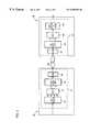
- FIG. 2is a block diagram illustrating a transmitter and receiver utilizing DMT according to an embodiment of the present invention.
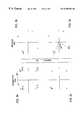
- FIGS. 3 a - 3 dschematically illustrate the constellation points associated with the transmission and reception of data using the transmitter/receiver of FIG. 2, according to an embodiment of the present invention.
- FIG. 4is a block diagram of a pair of nodes used in a network in accordance with an embodiment of the present invention.
- FIG. 5is a flow diagram illustrating the method for transmitting data according to an embodiment of the present invention.
- the present inventionwill be described with the example of a network node in a multi-point network using discrete multi-tone (DMT) technology.
- DMTdiscrete multi-tone
- a descriptionwill first be given of an exemplary DMT-based network, followed by the arrangement for providing an adaptive transmission system. It will become apparent, however, that the present invention is also applicable to other types of networks.
- FIG. 2illustrates an exemplary system in which the present invention may be advantageously employed.
- Network nodes 10 and 20are nodes, e.g., personal computers, in computer network 100 . Each node is capable of transmitting and receiving data over channel 40 . Channel 40 may be a twisted pair telephone line or another medium used to transmit data.
- Channel 40may be a twisted pair telephone line or another medium used to transmit data.
- a detailed transmitter 11is shown in network node 10 and a detailed receiver 21 is shown in network node 20 . It should be recognized, however, that each node 10 and 20 includes both the transmitter and receiver circuitry. Additionally, although not shown, other network nodes may be connected to nodes 10 and 20 in a ring topology, star topology or any other network topology.
- network 100 in FIG. 2utilizes DMT-based technology to transmit data over channel 40 .
- the present inventiondeparts from conventional DMT technology by utilizing a differential coder 12 to encode an input bit stream into a predetermined number of tones.
- differential coder 12uses 256 tones to encode the input bit stream.
- differential coder 12may utilize other numbers of tones to encode the bit stream, based on the particular network requirements.
- each toneis capable of transmitting up to 15 bits of data on the tone waveform.
- each toneis used to transmit two bits of data, which corresponds to four constellation points.
- the present inventionmay transmit other numbers of bits per tone.
- the differential coder 12overcomes the drawbacks associated with a home network environment by utilizing a reference tone encoded with a reference bit pattern, before transmitting the input data stream.
- a sequence of reference tonese.g., up to 256 tones, may be encoded with a reference bit pattern.
- Transmitter 11modulates the reference tone(s) to carry the predetermined bit pattern over channel 40 . For example, assume that bit pattern “00” is the predetermined bit pattern. The reference tone is then quadrature amplitude modulated to carry bit pattern “00”.
- the bit pattern “00”is represented by constellation point A in the complex plane shown in FIG. 3 a.
- the constellation pointrepresents the amplitude and phase of the signal at that particular tone.
- the Inverse Fast Fourier Transform (IFFT) block 14receives the tone information and converts the frequency domain-based tone information into a time domain-based waveform and outputs the time domain waveform to parallel-to-serial converter 16 .
- a guard-band cyclic prefixmay be applied between the IFFT block 14 and the parallel-to-serial converter 16 to transmit a prefix before the actual reference bits.
- the prefix datais discarded at the receiver 21 , thereby eliminating the effects of intersymbol interference (ISI) associated with the start of the transmission.
- Parallel-to-serial converter 16converts the data to a serial format for analog front end (AFE) block 18 .
- AFE block 18then transmits the data over channel 40 to node 20 .
- AFE block 22receives the line signal and performs amplification, filtering and digitizing. The signal is then fed into serial-to-parallel converter 24 . After the data is converted to a parallel format, FFT block 26 computes the amplitude and phase information of the reference tone.
- Differential decoder and slicer 28then decodes the reference signal, represented by constellation point B in FIG. 3 b.
- the transmitter 11transmits the actual input bit stream representing the data from network node 10 destined for network node 20 .
- the current bit stream being transmitted from node 10 to node 20is bit pattern “01”, which is illustrated by constellation point C in FIG. 3 c.
- the receiver 20receives the encoded carrier tone and processes the signal information using AFE block 22 , serial-to-parallel converter 24 , FFT block 26 and differential decoder and slicer block 28 .
- the tone informationis represented by constellation point D in FIG. 3 d.
- the receiver 21includes logic to compare the received point D with the previous received point B to determine the phase relationship between the points. Referring to FIG. 3 d, the phase relationship between points B and D is 90 degrees, with point D leading point B. Using this information, the decoder and slicer block 28 assumes that the transmitted data bits encoded via the second carrier tone is 90 degrees out of phase with the reference data bits.
- the reference data bit patternwas “00”, and a bit pattern leading “00” by 90 degrees maps to bit pattern “01”, as shown in FIG. 3 a. Therefore, the decoder and slicer block 28 in this example determines that the data bits transmitted with the second tone correspond to “01”.
- the transmitting node 10uses a reference tone encoded with a reference bit pattern at the beginning of every data packet.
- the phase distortion between the reference tone and the subsequent toneis then used to determine the value of the data associated with the first tone.
- Each successive toneis processed in a similar manner by comparing the phase relationship between the constellation point associated with the tone with the previous constellation point.
- the present inventionis then able to determine the value of the data transmitted on each tone without knowing the particular channel characteristics.
- the present inventionis able to decode transmitted data without the use of an equalizer to reverse the effect of amplitude attenuation or phase distortion associated with poor quality wiring.
- any receiving nodesince a known reference bit pattern is transmitted before each packet of data as a new reference, any receiving node is able to determine the values of the subsequent received data bits in that packet.
- the system for transmitting/receiving data of the present inventionis usable for different paths employing different channels in network 100 .
- the present inventionmay be advantageously employed in a multi-point network.
- a sending signalis transmitted only when there is data that needs to be transmitted.
- the transmitting nodetransmits a predetermined time mark to identify the beginning of a packet.
- the time markconsists of one cycle of a sinusoidal waveform.
- the receiver nodematches received patterns with the predefined time mark pattern to identify the start of the packet, and thus begin decoding the received packet.
- the time markmay be several cycles of a sinusoidal waveform or any other predetermined waveform.
- a predetermined transmitting node identifiermay also be transmitted after the time mark for identification purposes.
- An exemplary node IDmay consist of pulse amplitude modulated (PAM) sinusoidal waveforms unique to each network node.
- PAMpulse amplitude modulated
- the network nodes in network 100are able to transmit and receive data over channel 40 without knowing the particular channel characteristics.
- the present inventionis also able to adapt the transmission rate based on the particular channel characteristics. For example, if the channel characteristics of channel 40 are poor and the receiving node is unable to receive the transmitted data without errors, the transmitting node is able to adapt the transmission rate to ensure that error-free data is received.
- FIG. 4is a block diagram of network nodes 10 and 20 , in accordance with an embodiment of the present invention.
- Network node 10includes transmitter controller 32 and receiver controller 34 and network node 20 includes transmitter controller 42 and receiver controller 44 .
- transmitter/receiver controllers of nodes 10 and 11enable the present invention to optimize the data transmission rate, based on the particular operating conditions of channel 40 .
- the transmitter and receiver circuitry of FIG. 2are not depicted in nodes 10 and 20 of FIG. 4 in order not to unduly obscure the thrust of the present invention.
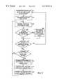
- FIG. 5is a flow diagram illustrating the method for providing an adaptive transmission system in accordance with an embodiment of the present invention.
- transmitter controller 32appends a cyclic redundancy check (CRC) code at the end of a packet of data to be transmitted over channel 40 .
- CRCcyclic redundancy check
- the CRC codeis included with the packet and therefore step 200 is skipped.
- other error check codesmay also be utilized.
- Node 10then encodes the data packet and CRC code at step 202 .
- node 10transmits the predetermined time mark along with the data stream and CRC code over channel 40 .
- the time markis a PAM sinusoidal signal one period in duration, optionally followed by node ID information.
- the time mark informationis transmitted at the start of each packet of data.
- the time marksessentially acts as a signal to alert the receiving node 20 that the data stream follows.
- the receiver controller 44When node 20 receives the data step 206 , the receiver controller 44 , illustrated in FIG. 4, checks the received data and CRC code to determine whether the data was received without errors. If the receiver controller 44 determines that the data was received without errors, the transmitter controller 42 of node 20 transmits the predetermined time mark back to the transmitting node 10 as an acknowledgement signal, at step 208 . Alternatively, any other predefined acknowledgement signal may be used. When the receiving node 20 determines that the data was received with errors at step 206 , the receiving node does not transmit the acknowledgement signal.
- the receiver controller 34 of transmitting node 10waits a predetermined period of time for the acknowledgment time mark from node 20 .
- the processreturns to step 200 for the transmission of a new packet. If the acknowledgment time mark is not received in the predetermined period of time, at step 210 , the transmitting node 10 assumes that the data packet was received with errors or was lost.
- the transmitter controller 32 of node 10determines whether the current packet has been transmitted a predetermined number of times.
- the predetermined numberis three.
- the predeterminedmay be any other number including one. If the current packet has not been transmitted the predetermined number of times, the process returns to step 204 where the current packet along with the time mark is retransmitted.
- the transmitter controller 32 of node 10then reduces the effective data rate by transmitting only a portion of the current data packet, along with at least one redundant copy of the portion. More specifically, at step 214 , the transmitter controller 32 retrieves a first predetermined number of bits at the head of the current data packet. For example, suppose the original data packet was 8 bits in length consisting of 11010001. At step 214 , the transmitter controller retrieves only the predetermined number of bits from the beginning of this packet. Further assume in this example that the predetermined number of bits is four. In this situation, the transmitter controller 32 retrieves bits “1101”, i.e., the first four bits of the current packet.
- the transmitter controller 32appends the appropriate CRC code to the end of the new bit pattern.
- the transmitter controller 32also provides at least one redundant copy of the new bit pattern and CRC code, after the first CRC code.
- the transmitter controller 32would provide the following bit pattern for encoding: 1101(CRCcode)1101(CRCcode).
- the number of redundant copies of the first bit patternwould generally be limited only by the bandwidth of the channel.
- the transmitting node 10encodes the new data packet, at step 218 , and transmitter controller 32 adds the time mark at the beginning of the packet to indicate the start of the packet. The process then returns to step 204 .
- the receiver controller 44determines whether any one of the redundant data patterns in the packet has been received without errors. For example, assume that the receiver controller 44 determines that the second group of bits, 1101 in the example described above, was received without errors, based on the CRC code information. The receiving node 20 at step 208 would then transmits an acknowledgement time mark to transmitting node 10 .
- a single reception of error-free data associated with any one of the redundant patternsenables the present invention to be more robust and to operate in conditions where conventional systems are unable to operate.
- steps 212 - 218continue until the receiver node 20 receives a group of data bits without errors and sends the acknowledgement signal to the transmitting node 10 .
- the transmitter controller 32reduces the number of bits of the current packet being transmitted and increases the number of redundant bit patterns.
- the transmitting node 10may transmit the first 256 bits of the 512 bits.
- the first 128 tonesare QAM to carry the first 256 bits.
- the next 128 adjacent tones in the frequency spectrumare similarly QAM to carry the redundant 256 bits.
- the processcould logically continue until the first tone carried a single bit of information followed by the remaining 255 tones carrying the same redundant bit.
- the present inventionwould decrease the bit rate to a predefined level, based on the particular network requirements, before the process is stopped.
- the transmitter controller 32may transmit control information after the time mark to indicate to the receiving node how the data information is to be interpreted. For example, after the time mark at the start of a packet and the optional node ID information, the transmitter controller 32 may transmit control information indicating the number of times a current packet is transmitted before the transmitter controller reduces the effective bit rate (step 212 in FIG. 5 ).
- the control informationmay also include information regarding how many bits of the current data packet are to be transmitted after the transmitter controller 32 reduces the effective bit rate (steps 214 - 218 in FIG. 5 ). In this manner, the receiver node 20 does not have to prestore control information regarding how to interpret the received data.
- the present inventionis able to adapt the transmission rate based on the particular channel characteristics. In situations where a particular channel experiences no errors at the maximum bit rate, the nodes utilize the maximum bandwidth and transmit data at the maximum rate. However, in situations where a channel is unable to support the maximum transmission rate, the present invention is advantageously able to reduce the transmission rate for that particular channel. In this manner, the present invention is able to optimize the data transmission rates between all nodes in a multi-point network, based on the particular channel characteristics. Additionally, the present invention is also able to be advantageously employed in a network environment, such as an in-home network, where wiring topology is non-standard.
Landscapes
- Engineering & Computer Science (AREA)
- Computer Networks & Wireless Communication (AREA)
- Signal Processing (AREA)
- Detection And Prevention Of Errors In Transmission (AREA)
Abstract
Description
Claims (17)
Priority Applications (1)
| Application Number | Priority Date | Filing Date | Title |
|---|---|---|---|
| US09/286,997US6590893B1 (en) | 1999-04-07 | 1999-04-07 | Adaptive transmission system in a network |
Applications Claiming Priority (1)
| Application Number | Priority Date | Filing Date | Title |
|---|---|---|---|
| US09/286,997US6590893B1 (en) | 1999-04-07 | 1999-04-07 | Adaptive transmission system in a network |
Publications (1)
| Publication Number | Publication Date |
|---|---|
| US6590893B1true US6590893B1 (en) | 2003-07-08 |
Family
ID=23101038
Family Applications (1)
| Application Number | Title | Priority Date | Filing Date |
|---|---|---|---|
| US09/286,997Expired - LifetimeUS6590893B1 (en) | 1999-04-07 | 1999-04-07 | Adaptive transmission system in a network |
Country Status (1)
| Country | Link |
|---|---|
| US (1) | US6590893B1 (en) |
Cited By (22)
| Publication number | Priority date | Publication date | Assignee | Title |
|---|---|---|---|---|
| US20010033612A1 (en)* | 2000-03-07 | 2001-10-25 | Miguel Peeters | Method to determine a channel characteristic, and discrete wavelet transmitter and receiver to perform the method |
| US20020064219A1 (en)* | 2000-10-05 | 2002-05-30 | Korea Electronics Technology Institute | Zipper type VDSL system |
| US20020114347A1 (en)* | 2001-02-17 | 2002-08-22 | Samsung Electronics Co., Ltd. | Initialization method for VDSL including tone space adjustment |
| US20030043777A1 (en)* | 2001-08-31 | 2003-03-06 | Juha Koponen | Method for optimizing performance in wireless networks |
| US6687370B1 (en)* | 1999-11-23 | 2004-02-03 | Telefonaktiebolaget Lm Ericsson (Publ) | Method and an arrangement for securing an ADSL connection |
| US6751263B1 (en)* | 1999-06-30 | 2004-06-15 | Infineon Technologies Ag | Method for the orthogonal frequency division modulation and demodulation |
| US20040120470A1 (en)* | 2002-12-23 | 2004-06-24 | Sbc Properties, L.P. | Equivalent working length determinative system for digital subscriber line circuits |
| US20040228417A1 (en)* | 2003-05-12 | 2004-11-18 | Mcnc Research And Development Institute | Communication system with adaptive channel correction |
| US20060039486A1 (en)* | 2004-08-17 | 2006-02-23 | Adaptive Spectrum And Signal Alignment, Inc. | DSL data collection system |
| US7031380B1 (en)* | 1999-09-28 | 2006-04-18 | Texas Instruments Incorporated | Multi-client ADSL modem |
| US20060120443A1 (en)* | 1999-09-28 | 2006-06-08 | Yaqi Cheng | Multi-client ADSL modem |
| US20060203716A1 (en)* | 2005-02-25 | 2006-09-14 | Gilligan Douglas A | Error detection and recovery of an optical network element |
| US7298693B1 (en) | 1999-10-21 | 2007-11-20 | Tellabs Operations, Inc. | Reverse notification tree for data networks |
| US20070282013A1 (en)* | 2003-07-04 | 2007-12-06 | Lajos Szente | Pharmaceutical Compositions Comprising Peranhydrocyclodextrin |
| US7315510B1 (en) | 1999-10-21 | 2008-01-01 | Tellabs Operations, Inc. | Method and apparatus for detecting MPLS network failures |
| US20080132211A1 (en)* | 2005-09-30 | 2008-06-05 | Abtin Keshavarzian | System, method and apparatus employing tones and/or tone patterns to indicate the message type in wireless sensor networks |
| US20090222884A1 (en)* | 2003-04-09 | 2009-09-03 | Microsoft Corporation | Interfaces and methods for group policy management |
| US7796504B1 (en)* | 1999-10-21 | 2010-09-14 | Tellabs Operations, Inc. | Method for establishing an MPLS data network protection pathway |
| US20100315981A1 (en)* | 2005-09-30 | 2010-12-16 | Abtin Keshavarzian | System, method and apparatus employing tone and/or tone patterns to indicate the message type in wireless sensor networks |
| US20110058472A1 (en)* | 1999-10-25 | 2011-03-10 | Owens Kenneth R | Protection/restoration of mpls networks |
| US9755876B2 (en) | 1999-11-09 | 2017-09-05 | Tq Delta, Llc | System and method for scrambling the phase of the carriers in a multicarrier communications system |
| US9838531B2 (en) | 2000-01-07 | 2017-12-05 | Tq Delta, Llc | Systems and methods for establishing a diagnostic transmission mode and communicating over the same |
Citations (8)
| Publication number | Priority date | Publication date | Assignee | Title |
|---|---|---|---|---|
| US4661657A (en)* | 1982-05-07 | 1987-04-28 | Siemens Aktiengesellschaft | Method and apparatus for transmitting and receiving encoded data |
| US5426643A (en)* | 1993-11-01 | 1995-06-20 | Motorola Inc. | Apparatus and method for transmitting bit synchronous data over an unreliable channel |
| US5477550A (en)* | 1993-03-08 | 1995-12-19 | Crisler; Kenneth J. | Method for communicating data using a modified SR-ARQ protocol |
| US5666383A (en)* | 1996-05-08 | 1997-09-09 | International Business Machines Corporation | Variable rate discrete multiple tone bidirectional transmission |
| US5910970A (en)* | 1996-05-09 | 1999-06-08 | Texas Instruments Incorporated | MDSL host interface requirement specification |
| US6134274A (en)* | 1997-12-23 | 2000-10-17 | At&T Corp | Method and apparatus for allocating data for transmission via discrete multiple tones |
| US6157612A (en)* | 1995-04-03 | 2000-12-05 | Lucent Technologies Inc. | Fast fading packet diversity transmission method and system |
| US6415410B1 (en)* | 1995-05-09 | 2002-07-02 | Nokia Telecommunications Oy | Sliding-window data flow control using an adjustable window size |
- 1999
- 1999-04-07USUS09/286,997patent/US6590893B1/ennot_activeExpired - Lifetime
Patent Citations (8)
| Publication number | Priority date | Publication date | Assignee | Title |
|---|---|---|---|---|
| US4661657A (en)* | 1982-05-07 | 1987-04-28 | Siemens Aktiengesellschaft | Method and apparatus for transmitting and receiving encoded data |
| US5477550A (en)* | 1993-03-08 | 1995-12-19 | Crisler; Kenneth J. | Method for communicating data using a modified SR-ARQ protocol |
| US5426643A (en)* | 1993-11-01 | 1995-06-20 | Motorola Inc. | Apparatus and method for transmitting bit synchronous data over an unreliable channel |
| US6157612A (en)* | 1995-04-03 | 2000-12-05 | Lucent Technologies Inc. | Fast fading packet diversity transmission method and system |
| US6415410B1 (en)* | 1995-05-09 | 2002-07-02 | Nokia Telecommunications Oy | Sliding-window data flow control using an adjustable window size |
| US5666383A (en)* | 1996-05-08 | 1997-09-09 | International Business Machines Corporation | Variable rate discrete multiple tone bidirectional transmission |
| US5910970A (en)* | 1996-05-09 | 1999-06-08 | Texas Instruments Incorporated | MDSL host interface requirement specification |
| US6134274A (en)* | 1997-12-23 | 2000-10-17 | At&T Corp | Method and apparatus for allocating data for transmission via discrete multiple tones |
Cited By (46)
| Publication number | Priority date | Publication date | Assignee | Title |
|---|---|---|---|---|
| US6751263B1 (en)* | 1999-06-30 | 2004-06-15 | Infineon Technologies Ag | Method for the orthogonal frequency division modulation and demodulation |
| US20060120443A1 (en)* | 1999-09-28 | 2006-06-08 | Yaqi Cheng | Multi-client ADSL modem |
| US7031380B1 (en)* | 1999-09-28 | 2006-04-18 | Texas Instruments Incorporated | Multi-client ADSL modem |
| US7315510B1 (en) | 1999-10-21 | 2008-01-01 | Tellabs Operations, Inc. | Method and apparatus for detecting MPLS network failures |
| US20080095045A1 (en)* | 1999-10-21 | 2008-04-24 | Tellabs Operations, Inc. | Method and Apparatus for Detecting MPLS Network Failures |
| US8737203B2 (en) | 1999-10-21 | 2014-05-27 | Tellabs Operations, Inc. | Method for establishing an MPLS data network protection pathway |
| US7796504B1 (en)* | 1999-10-21 | 2010-09-14 | Tellabs Operations, Inc. | Method for establishing an MPLS data network protection pathway |
| US8588058B2 (en) | 1999-10-21 | 2013-11-19 | Tellabs Operations, Inc. | Reverse notification tree for data networks |
| US8130637B2 (en) | 1999-10-21 | 2012-03-06 | Tellabs Operations, Inc. | Method and apparatus for detecting MPLS network failures |
| US7298693B1 (en) | 1999-10-21 | 2007-11-20 | Tellabs Operations, Inc. | Reverse notification tree for data networks |
| US7881184B2 (en) | 1999-10-21 | 2011-02-01 | Tellabs Operations, Inc. | Reverse notification tree for data networks |
| US20100296393A1 (en)* | 1999-10-21 | 2010-11-25 | Owens Kenneth R | Method for establishing an mpls data network protection pathway |
| US20110058472A1 (en)* | 1999-10-25 | 2011-03-10 | Owens Kenneth R | Protection/restoration of mpls networks |
| US8842516B2 (en) | 1999-10-25 | 2014-09-23 | Tellabs Operations, Inc. | Protection/restoration of MPLS networks |
| US10187240B2 (en) | 1999-11-09 | 2019-01-22 | Tq Delta, Llc | System and method for scrambling the phase of the carriers in a multicarrier communications system |
| US9755876B2 (en) | 1999-11-09 | 2017-09-05 | Tq Delta, Llc | System and method for scrambling the phase of the carriers in a multicarrier communications system |
| US6687370B1 (en)* | 1999-11-23 | 2004-02-03 | Telefonaktiebolaget Lm Ericsson (Publ) | Method and an arrangement for securing an ADSL connection |
| US20180249001A1 (en)* | 2000-01-07 | 2018-08-30 | Tq Delta, Llc | Systems and methods for establishing a diagnostic transmission mode and communicating over the same |
| US9973624B2 (en) | 2000-01-07 | 2018-05-15 | Tq Delta, Llc | Systems and methods for establishing a diagnostic transmission mode and communicating over the same |
| US9838531B2 (en) | 2000-01-07 | 2017-12-05 | Tq Delta, Llc | Systems and methods for establishing a diagnostic transmission mode and communicating over the same |
| US10264119B2 (en) | 2000-01-07 | 2019-04-16 | Tq Delta, Llc | Systems and methods for establishing a diagnostic transmission mode and communicating over the same |
| US10623559B2 (en)* | 2000-01-07 | 2020-04-14 | Tq Delta, Llc | Systems and methods for establishing a diagnostic transmission mode and communicating over the same |
| US20010033612A1 (en)* | 2000-03-07 | 2001-10-25 | Miguel Peeters | Method to determine a channel characteristic, and discrete wavelet transmitter and receiver to perform the method |
| US6952441B2 (en)* | 2000-03-07 | 2005-10-04 | Alcatel | Method to determine a channel characteristic, and discrete wavelet transmitter and receiver to perform the method |
| US20020064219A1 (en)* | 2000-10-05 | 2002-05-30 | Korea Electronics Technology Institute | Zipper type VDSL system |
| US6862261B2 (en)* | 2000-10-05 | 2005-03-01 | Korea Electronics Technology Institute | Zipper type VDSL system |
| US20020114347A1 (en)* | 2001-02-17 | 2002-08-22 | Samsung Electronics Co., Ltd. | Initialization method for VDSL including tone space adjustment |
| US7151779B2 (en)* | 2001-02-17 | 2006-12-19 | Samsung Electronics Co., Ltd. | Initialization method for VDSL including tone space adjustment |
| US7177277B2 (en)* | 2001-08-31 | 2007-02-13 | First Hop Oy | Method for optimizing performance in wireless networks |
| US20030043777A1 (en)* | 2001-08-31 | 2003-03-06 | Juha Koponen | Method for optimizing performance in wireless networks |
| US7620154B2 (en) | 2002-12-23 | 2009-11-17 | Cambron G Keith | Equivalent working length determinative system for digital subscriber line circuits |
| US20040120470A1 (en)* | 2002-12-23 | 2004-06-24 | Sbc Properties, L.P. | Equivalent working length determinative system for digital subscriber line circuits |
| US20090222884A1 (en)* | 2003-04-09 | 2009-09-03 | Microsoft Corporation | Interfaces and methods for group policy management |
| US20040228417A1 (en)* | 2003-05-12 | 2004-11-18 | Mcnc Research And Development Institute | Communication system with adaptive channel correction |
| US20070282013A1 (en)* | 2003-07-04 | 2007-12-06 | Lajos Szente | Pharmaceutical Compositions Comprising Peranhydrocyclodextrin |
| US7535966B2 (en) | 2004-08-17 | 2009-05-19 | Adaptive Spectrum And Signal Alignment, Inc. | DSL data collection system |
| US8045629B1 (en) | 2004-08-17 | 2011-10-25 | Adaptive Spectrum And Signal Alignment, Inc. | DSL data collection system |
| US20060039486A1 (en)* | 2004-08-17 | 2006-02-23 | Adaptive Spectrum And Signal Alignment, Inc. | DSL data collection system |
| US20060203716A1 (en)* | 2005-02-25 | 2006-09-14 | Gilligan Douglas A | Error detection and recovery of an optical network element |
| US7734173B2 (en) | 2005-02-25 | 2010-06-08 | Dynamic Method Enterprises Limited | Error detection and recovery of an optical network element |
| WO2006093791A3 (en)* | 2005-02-25 | 2007-11-01 | Intellambda Systems Inc | Error detection and recovery of an optical network element |
| US8010091B2 (en) | 2005-09-30 | 2011-08-30 | Abtin Keshavarzian | System, method and apparatus employing tone and/or tone patterns to indicate the message type in wireless sensor networks |
| US20100315981A1 (en)* | 2005-09-30 | 2010-12-16 | Abtin Keshavarzian | System, method and apparatus employing tone and/or tone patterns to indicate the message type in wireless sensor networks |
| US7720465B2 (en) | 2005-09-30 | 2010-05-18 | Robert Bosch Gmbh | System, method and apparatus employing tones and/or tone patterns to indicate the message type in wireless sensor networks |
| US20080132211A1 (en)* | 2005-09-30 | 2008-06-05 | Abtin Keshavarzian | System, method and apparatus employing tones and/or tone patterns to indicate the message type in wireless sensor networks |
| WO2008066692A3 (en)* | 2006-11-30 | 2009-04-09 | Bosch Gmbh Robert | System employing tone or tone patterns to indicate message type in wireless sensor networks |
Similar Documents
| Publication | Publication Date | Title |
|---|---|---|
| US6590893B1 (en) | Adaptive transmission system in a network | |
| US10148591B2 (en) | Method and multi-carrier transceiver with stored application profiles for supporting multiple applications | |
| US6549512B2 (en) | MDSL DMT architecture | |
| EP1848138B1 (en) | Protection of communication systems against repetitive electrical impulse noise | |
| EP2467987A2 (en) | Concatenated repetition code with convolutional code | |
| EP1990965B1 (en) | Multicarrier system with stored application profiles for supporting multiple applications | |
| US6434188B1 (en) | Differential encoding arrangement for a discrete multi-tone transmission system | |
| US6442173B1 (en) | Timing recovery scheme for a discrete multitone transmission system | |
| US6075795A (en) | Collision detection system for multiple stations in discrete multi-tone data communications network | |
| US6535550B1 (en) | Transceiver with variable width cyclic prefix | |
| US6456602B1 (en) | Method and apparatus for achieving frequency diversity by use of multiple images | |
| US6690666B1 (en) | Packet modulation for DSL | |
| US6339599B1 (en) | Collision handling scheme for discrete multi-tone data communications network | |
| US6577598B1 (en) | Methods and apparatus for channel adaptation in a DMT based system | |
| US6175316B1 (en) | Bin-to-bin differential encoding apparatus and method for a discrete multi-tone transmission system | |
| US6714589B1 (en) | Communication device with primitive synchronization signal | |
| US6449262B1 (en) | Method and apparatus for frequency shifting with a clock signal | |
| KR100591644B1 (en) | Method and system for synchronizing time-division-duplexed transceivers | |
| CA2793007C (en) | Multicarrier system with stored application profiles for supporting multiple applications | |
| KR20020035956A (en) | Method for initialization protocol of discrete multi-tone system for time division duplexing/time division multiple access type using power line communication | |
| KR20020041034A (en) | Adaptive Alternate Mark Duty Inversion Method for ISI Subtraction | |
| CA2353739A1 (en) | An improved scheme for the initialization of adsl modems |
Legal Events
| Date | Code | Title | Description |
|---|---|---|---|
| AS | Assignment | Owner name:ADVANCED MICRO DEVICES, INC., CALIFORNIA Free format text:ASSIGNMENT OF ASSIGNORS INTEREST;ASSIGNORS:HWANG, CHIEN-MEEN;GERSHON, EUGEN;BARSOUM, MAGED F.;AND OTHERS;REEL/FRAME:009887/0172 Effective date:19990406 | |
| AS | Assignment | Owner name:MORGAN STANLEY & CO. INCORPORATED, NEW YORK Free format text:SECURITY INTEREST;ASSIGNOR:LEGERITY, INC.;REEL/FRAME:011601/0539 Effective date:20000804 | |
| AS | Assignment | Owner name:LEGERITY, INC., TEXAS Free format text:ASSIGNMENT OF ASSIGNORS INTEREST;ASSIGNOR:ADVANCED MICRO DEVICES, INC.;REEL/FRAME:011700/0686 Effective date:20000731 | |
| AS | Assignment | Owner name:MORGAN STANLEY & CO. INCORPORATED, AS FACILITY COL Free format text:SECURITY AGREEMENT;ASSIGNORS:LEGERITY, INC.;LEGERITY HOLDINGS, INC.;LEGERITY INTERNATIONAL, INC.;REEL/FRAME:013372/0063 Effective date:20020930 | |
| STCF | Information on status: patent grant | Free format text:PATENTED CASE | |
| AS | Assignment | Owner name:ADVANCED MICRO DEVICES, INC., CALIFORNIA Free format text:ASSIGNMENT OF ASSIGNORS INTEREST;ASSIGNOR:LEGERITY, INC.;REEL/FRAME:017921/0471 Effective date:20051115 | |
| FPAY | Fee payment | Year of fee payment:4 | |
| AS | Assignment | Owner name:GLOBALFOUNDRIES INC., CAYMAN ISLANDS Free format text:AFFIRMATION OF PATENT ASSIGNMENT;ASSIGNOR:ADVANCED MICRO DEVICES, INC.;REEL/FRAME:023119/0083 Effective date:20090630 | |
| FPAY | Fee payment | Year of fee payment:8 | |
| FPAY | Fee payment | Year of fee payment:12 | |
| AS | Assignment | Owner name:WILMINGTON TRUST, NATIONAL ASSOCIATION, DELAWARE Free format text:SECURITY AGREEMENT;ASSIGNOR:GLOBALFOUNDRIES INC.;REEL/FRAME:049490/0001 Effective date:20181127 | |
| AS | Assignment | Owner name:GLOBALFOUNDRIES INC., CAYMAN ISLANDS Free format text:RELEASE BY SECURED PARTY;ASSIGNOR:WILMINGTON TRUST, NATIONAL ASSOCIATION;REEL/FRAME:054636/0001 Effective date:20201117 | |
| AS | Assignment | Owner name:GLOBALFOUNDRIES U.S. INC., NEW YORK Free format text:RELEASE BY SECURED PARTY;ASSIGNOR:WILMINGTON TRUST, NATIONAL ASSOCIATION;REEL/FRAME:056987/0001 Effective date:20201117 |