US6589778B1 - Method and apparatus for performing biological reactions on a substrate surface - Google Patents
Method and apparatus for performing biological reactions on a substrate surfaceDownload PDFInfo
- Publication number
- US6589778B1 US6589778B1US09/464,490US46449099AUS6589778B1US 6589778 B1US6589778 B1US 6589778B1US 46449099 AUS46449099 AUS 46449099AUS 6589778 B1US6589778 B1US 6589778B1
- Authority
- US
- United States
- Prior art keywords
- layer
- port
- array
- slide
- substrate
- Prior art date
- Legal status (The legal status is an assumption and is not a legal conclusion. Google has not performed a legal analysis and makes no representation as to the accuracy of the status listed.)
- Expired - Fee Related
Links
Images


Classifications
- B—PERFORMING OPERATIONS; TRANSPORTING
- B01—PHYSICAL OR CHEMICAL PROCESSES OR APPARATUS IN GENERAL
- B01L—CHEMICAL OR PHYSICAL LABORATORY APPARATUS FOR GENERAL USE
- B01L3/00—Containers or dishes for laboratory use, e.g. laboratory glassware; Droppers
- B01L3/50—Containers for the purpose of retaining a material to be analysed, e.g. test tubes
- B01L3/502—Containers for the purpose of retaining a material to be analysed, e.g. test tubes with fluid transport, e.g. in multi-compartment structures
- B01L3/5027—Containers for the purpose of retaining a material to be analysed, e.g. test tubes with fluid transport, e.g. in multi-compartment structures by integrated microfluidic structures, i.e. dimensions of channels and chambers are such that surface tension forces are important, e.g. lab-on-a-chip
- B—PERFORMING OPERATIONS; TRANSPORTING
- B01—PHYSICAL OR CHEMICAL PROCESSES OR APPARATUS IN GENERAL
- B01L—CHEMICAL OR PHYSICAL LABORATORY APPARATUS FOR GENERAL USE
- B01L3/00—Containers or dishes for laboratory use, e.g. laboratory glassware; Droppers
- B01L3/50—Containers for the purpose of retaining a material to be analysed, e.g. test tubes
- B01L3/508—Containers for the purpose of retaining a material to be analysed, e.g. test tubes rigid containers not provided for above
- B01L3/5085—Containers for the purpose of retaining a material to be analysed, e.g. test tubes rigid containers not provided for above for multiple samples, e.g. microtitration plates
- B01L3/50853—Containers for the purpose of retaining a material to be analysed, e.g. test tubes rigid containers not provided for above for multiple samples, e.g. microtitration plates with covers or lids
- B—PERFORMING OPERATIONS; TRANSPORTING
- B01—PHYSICAL OR CHEMICAL PROCESSES OR APPARATUS IN GENERAL
- B01J—CHEMICAL OR PHYSICAL PROCESSES, e.g. CATALYSIS OR COLLOID CHEMISTRY; THEIR RELEVANT APPARATUS
- B01J2219/00—Chemical, physical or physico-chemical processes in general; Their relevant apparatus
- B01J2219/00274—Sequential or parallel reactions; Apparatus and devices for combinatorial chemistry or for making arrays; Chemical library technology
- B01J2219/00583—Features relative to the processes being carried out
- B01J2219/00596—Solid-phase processes
- B—PERFORMING OPERATIONS; TRANSPORTING
- B01—PHYSICAL OR CHEMICAL PROCESSES OR APPARATUS IN GENERAL
- B01J—CHEMICAL OR PHYSICAL PROCESSES, e.g. CATALYSIS OR COLLOID CHEMISTRY; THEIR RELEVANT APPARATUS
- B01J2219/00—Chemical, physical or physico-chemical processes in general; Their relevant apparatus
- B01J2219/00274—Sequential or parallel reactions; Apparatus and devices for combinatorial chemistry or for making arrays; Chemical library technology
- B01J2219/00583—Features relative to the processes being carried out
- B01J2219/00603—Making arrays on substantially continuous surfaces
- B01J2219/00659—Two-dimensional arrays
- B—PERFORMING OPERATIONS; TRANSPORTING
- B01—PHYSICAL OR CHEMICAL PROCESSES OR APPARATUS IN GENERAL
- B01J—CHEMICAL OR PHYSICAL PROCESSES, e.g. CATALYSIS OR COLLOID CHEMISTRY; THEIR RELEVANT APPARATUS
- B01J2219/00—Chemical, physical or physico-chemical processes in general; Their relevant apparatus
- B01J2219/00274—Sequential or parallel reactions; Apparatus and devices for combinatorial chemistry or for making arrays; Chemical library technology
- B01J2219/0068—Means for controlling the apparatus of the process
- B01J2219/00702—Processes involving means for analysing and characterising the products
- B—PERFORMING OPERATIONS; TRANSPORTING
- B01—PHYSICAL OR CHEMICAL PROCESSES OR APPARATUS IN GENERAL
- B01J—CHEMICAL OR PHYSICAL PROCESSES, e.g. CATALYSIS OR COLLOID CHEMISTRY; THEIR RELEVANT APPARATUS
- B01J2219/00—Chemical, physical or physico-chemical processes in general; Their relevant apparatus
- B01J2219/00274—Sequential or parallel reactions; Apparatus and devices for combinatorial chemistry or for making arrays; Chemical library technology
- B01J2219/00718—Type of compounds synthesised
- B01J2219/0072—Organic compounds
- B01J2219/00722—Nucleotides
- B—PERFORMING OPERATIONS; TRANSPORTING
- B01—PHYSICAL OR CHEMICAL PROCESSES OR APPARATUS IN GENERAL
- B01L—CHEMICAL OR PHYSICAL LABORATORY APPARATUS FOR GENERAL USE
- B01L2200/00—Solutions for specific problems relating to chemical or physical laboratory apparatus
- B01L2200/02—Adapting objects or devices to another
- B01L2200/026—Fluid interfacing between devices or objects, e.g. connectors, inlet details
- B01L2200/027—Fluid interfacing between devices or objects, e.g. connectors, inlet details for microfluidic devices
- B—PERFORMING OPERATIONS; TRANSPORTING
- B01—PHYSICAL OR CHEMICAL PROCESSES OR APPARATUS IN GENERAL
- B01L—CHEMICAL OR PHYSICAL LABORATORY APPARATUS FOR GENERAL USE
- B01L2200/00—Solutions for specific problems relating to chemical or physical laboratory apparatus
- B01L2200/06—Fluid handling related problems
- B01L2200/0684—Venting, avoiding backpressure, avoid gas bubbles
- B—PERFORMING OPERATIONS; TRANSPORTING
- B01—PHYSICAL OR CHEMICAL PROCESSES OR APPARATUS IN GENERAL
- B01L—CHEMICAL OR PHYSICAL LABORATORY APPARATUS FOR GENERAL USE
- B01L2200/00—Solutions for specific problems relating to chemical or physical laboratory apparatus
- B01L2200/10—Integrating sample preparation and analysis in single entity, e.g. lab-on-a-chip concept
- B—PERFORMING OPERATIONS; TRANSPORTING
- B01—PHYSICAL OR CHEMICAL PROCESSES OR APPARATUS IN GENERAL
- B01L—CHEMICAL OR PHYSICAL LABORATORY APPARATUS FOR GENERAL USE
- B01L2300/00—Additional constructional details
- B01L2300/06—Auxiliary integrated devices, integrated components
- B01L2300/0627—Sensor or part of a sensor is integrated
- B01L2300/0636—Integrated biosensor, microarrays
- B—PERFORMING OPERATIONS; TRANSPORTING
- B01—PHYSICAL OR CHEMICAL PROCESSES OR APPARATUS IN GENERAL
- B01L—CHEMICAL OR PHYSICAL LABORATORY APPARATUS FOR GENERAL USE
- B01L2300/00—Additional constructional details
- B01L2300/06—Auxiliary integrated devices, integrated components
- B01L2300/0627—Sensor or part of a sensor is integrated
- B01L2300/0654—Lenses; Optical fibres
- B—PERFORMING OPERATIONS; TRANSPORTING
- B01—PHYSICAL OR CHEMICAL PROCESSES OR APPARATUS IN GENERAL
- B01L—CHEMICAL OR PHYSICAL LABORATORY APPARATUS FOR GENERAL USE
- B01L2300/00—Additional constructional details
- B01L2300/08—Geometry, shape and general structure
- B01L2300/0809—Geometry, shape and general structure rectangular shaped
- B01L2300/0822—Slides
- B—PERFORMING OPERATIONS; TRANSPORTING
- B01—PHYSICAL OR CHEMICAL PROCESSES OR APPARATUS IN GENERAL
- B01L—CHEMICAL OR PHYSICAL LABORATORY APPARATUS FOR GENERAL USE
- B01L2300/00—Additional constructional details
- B01L2300/08—Geometry, shape and general structure
- B01L2300/0861—Configuration of multiple channels and/or chambers in a single devices
- B01L2300/0877—Flow chambers
- B—PERFORMING OPERATIONS; TRANSPORTING
- B01—PHYSICAL OR CHEMICAL PROCESSES OR APPARATUS IN GENERAL
- B01L—CHEMICAL OR PHYSICAL LABORATORY APPARATUS FOR GENERAL USE
- B01L2300/00—Additional constructional details
- B01L2300/12—Specific details about materials
- B01L2300/123—Flexible; Elastomeric
- B—PERFORMING OPERATIONS; TRANSPORTING
- B01—PHYSICAL OR CHEMICAL PROCESSES OR APPARATUS IN GENERAL
- B01L—CHEMICAL OR PHYSICAL LABORATORY APPARATUS FOR GENERAL USE
- B01L2300/00—Additional constructional details
- B01L2300/18—Means for temperature control
- B01L2300/1805—Conductive heating, heat from thermostatted solids is conducted to receptacles, e.g. heating plates, blocks
- B01L2300/1822—Conductive heating, heat from thermostatted solids is conducted to receptacles, e.g. heating plates, blocks using Peltier elements
- B—PERFORMING OPERATIONS; TRANSPORTING
- B01—PHYSICAL OR CHEMICAL PROCESSES OR APPARATUS IN GENERAL
- B01L—CHEMICAL OR PHYSICAL LABORATORY APPARATUS FOR GENERAL USE
- B01L2300/00—Additional constructional details
- B01L2300/18—Means for temperature control
- B01L2300/1805—Conductive heating, heat from thermostatted solids is conducted to receptacles, e.g. heating plates, blocks
- B01L2300/1827—Conductive heating, heat from thermostatted solids is conducted to receptacles, e.g. heating plates, blocks using resistive heater
- B—PERFORMING OPERATIONS; TRANSPORTING
- B01—PHYSICAL OR CHEMICAL PROCESSES OR APPARATUS IN GENERAL
- B01L—CHEMICAL OR PHYSICAL LABORATORY APPARATUS FOR GENERAL USE
- B01L2300/00—Additional constructional details
- B01L2300/18—Means for temperature control
- B01L2300/1861—Means for temperature control using radiation
- B01L2300/1866—Microwaves
- B—PERFORMING OPERATIONS; TRANSPORTING
- B01—PHYSICAL OR CHEMICAL PROCESSES OR APPARATUS IN GENERAL
- B01L—CHEMICAL OR PHYSICAL LABORATORY APPARATUS FOR GENERAL USE
- B01L2400/00—Moving or stopping fluids
- B01L2400/04—Moving fluids with specific forces or mechanical means
- B01L2400/0475—Moving fluids with specific forces or mechanical means specific mechanical means and fluid pressure
- B01L2400/0481—Moving fluids with specific forces or mechanical means specific mechanical means and fluid pressure squeezing of channels or chambers
- B—PERFORMING OPERATIONS; TRANSPORTING
- B01—PHYSICAL OR CHEMICAL PROCESSES OR APPARATUS IN GENERAL
- B01L—CHEMICAL OR PHYSICAL LABORATORY APPARATUS FOR GENERAL USE
- B01L2400/00—Moving or stopping fluids
- B01L2400/04—Moving fluids with specific forces or mechanical means
- B01L2400/0475—Moving fluids with specific forces or mechanical means specific mechanical means and fluid pressure
- B01L2400/0487—Moving fluids with specific forces or mechanical means specific mechanical means and fluid pressure fluid pressure, pneumatics
- B—PERFORMING OPERATIONS; TRANSPORTING
- B01—PHYSICAL OR CHEMICAL PROCESSES OR APPARATUS IN GENERAL
- B01L—CHEMICAL OR PHYSICAL LABORATORY APPARATUS FOR GENERAL USE
- B01L2400/00—Moving or stopping fluids
- B01L2400/06—Valves, specific forms thereof
- B01L2400/0677—Valves, specific forms thereof phase change valves; Meltable, freezing, dissolvable plugs; Destructible barriers
- B—PERFORMING OPERATIONS; TRANSPORTING
- B01—PHYSICAL OR CHEMICAL PROCESSES OR APPARATUS IN GENERAL
- B01L—CHEMICAL OR PHYSICAL LABORATORY APPARATUS FOR GENERAL USE
- B01L9/00—Supporting devices; Holding devices
- B01L9/52—Supports specially adapted for flat sample carriers, e.g. for plates, slides, chips
- B01L9/527—Supports specially adapted for flat sample carriers, e.g. for plates, slides, chips for microfluidic devices, e.g. used for lab-on-a-chip
- C—CHEMISTRY; METALLURGY
- C07—ORGANIC CHEMISTRY
- C07B—GENERAL METHODS OF ORGANIC CHEMISTRY; APPARATUS THEREFOR
- C07B2200/00—Indexing scheme relating to specific properties of organic compounds
- C07B2200/11—Compounds covalently bound to a solid support
- C—CHEMISTRY; METALLURGY
- C40—COMBINATORIAL TECHNOLOGY
- C40B—COMBINATORIAL CHEMISTRY; LIBRARIES, e.g. CHEMICAL LIBRARIES
- C40B40/00—Libraries per se, e.g. arrays, mixtures
- C40B40/04—Libraries containing only organic compounds
- C40B40/06—Libraries containing nucleotides or polynucleotides, or derivatives thereof
Definitions
- the present inventionrelates to an apparatus for performing biological reactions. Specifically, the invention relates to an apparatus for performing nucleic acid hybridization reactions on a substrate layer having a multiplicity of oligonucleotide binding sites disposed thereon.
- Nucleic acid hybridization assaysare advantageously performed using probe array technology, which utilizes binding of target single-stranded DNA onto immobilized DNA (usually, oligonucleotide) probes.
- the detection limit of a nucleic acid hybridization assayis determined by the sensitivity of the detection device, and also by the amount of target nucleic acid available to be bound to probes, typically oligonucleotide probes, during hybridization.
- U.S. Pat. No. 5,545,531 to Rava et al.discloses a hybridization plate comprising a multiplicity of oligonucleotide arrays.
- U.S. Pat. No. 5,922,591 to Anderson et al.discloses a miniaturized hybridization chamber for use with oligonucleotide arrays.
- U.S. Pat. No. 5,945,334 to Besemerdiscloses oligonucleotide array packaging.
- oligonucleotide array technologydoes not provide maximum hybridization efficiency.
- Existing nucleic acid hybridization assay equipmentincludes numerous components, each of which is a source of inefficiency and inaccuracy.
- Hybridization using oligonucleotide arraysmust be performed in a volume in which a small amount of target DNA or other nucleic acid can be efficiently annealed to the immobilized probes.
- target DNA moleculesare often obtained in minute ( ⁇ picomol) quantities. In practice, it can take several (tens of) hours for hybridization to be substantially complete at the low target nucleic acid levels available for biological samples.
- array hybridizationis conventionally performed in a stationary hybridization chamber where active mixing is absent.
- the probability that a particular target molecule will hybridize to a complementary oligonucleotide probe immobilized on a surfaceis determined by the concentration of the target, the diffusion rate of the target molecule and the statistics of interaction between the target and the complementary oligonucleotide.
- oligonucleotide array hybridizationrequires a great deal of operator attentiveness and manipulation, and the degree of skill required to perform the analysis is high.
- hybridizationis typically performed in an assay chamber, and then data collection and analysis are performed in a separate apparatus (such as a laser scanner or fluorescence microscope). This arrangement requires a substantial amount of handling by the user, and makes the assays both time-consuming and subject to user error.
- the inventionprovides an apparatus in which biological reactions such as nucleic acid hybridization can be performed.
- the apparatus of the inventionis a hybridization chamber comprising a flexible layer attached to a biochip by an adhesive layer.
- the biochipcomprises a substrate having a first surface and a second surface, wherein the first surface contains an array of biologically reactive sites, preferably an oligonucleotide array.
- the arrayis provided in an area bounded by the adhesive layer set down on the first substrate surface.
- the flexible layermost preferably is both deformable and translucent.
- the chamberalso includes a first port, and certain embodiments further include a second port, that transverses the substrate and comprises a first opening on the first substrate surface and a second opening on the second substrate surface.
- the openings of these ports on the second substrate surfaceare covered by a removable cover, most preferably a foil tape.
- the openings of these ports on the first substrate surfaceare provided within the area bounded by the adhesive layer.
- the adhesive layer, the flexible layer and the substratealso define a volume that is filled with a water-soluble compound.
- the water-soluble compoundis preferably a solid at certain temperatures, most preferably at or below room temperature, and a liquid at elevated temperatures, most preferably below about 100° C.
- the substratecomprises a multiplicity of oligonucleotide arrays, which are contained in one or a plurality of areas bounded by the adhesive layer and covered by the flexible layer.
- each area bounded by the adhesive layeralso comprises a first port and can also comprise a second port.
- the hybridization chamberis optionally supplied with a heater, most preferably a resistive heater, in thermal contact with the flexible layer.
- the chamberis also optionally supplied with a roller, most preferably a patterned roller, positioned in contact with the flexible layer and movable longitudinally across the surface of the chamber for mixing hybridization fluid and wash solutions as required.
- the chamberis further optionally supplied with a scanner positioned in contact with the flexible layer and movable longitudinally across the surface of the chamber for detecting hybridization signals, most preferably produced by fluorescently-labeled target nucleic acid.
- the inventionprovides a handheld device comprising a lid, a base, a carriage embodying a roller, a scanner, a heating element and a thermocouple, wherein the hybridization chamber of the invention is positioned above and in removable contact with the carriage.
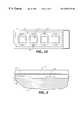
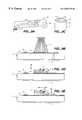
- FIGS. 1A-1Dare views of a preferred embodiment of the present invention illustrating the preparation of a chamber for reaction.
- FIG. 1Ais a cross-sectional view of the apparatus illustrating a hybridization chamber prefilled with a water-soluble compound in thermal contact with a heating element.
- FIG. 1Bis a cross sectional view of the apparatus illustrating the mixing of the water-soluble compound and the biological sample fluid.
- FIG. 1Cis a cross sectional view of the apparatus illustrating a chamber filled with the sample fluid/water-soluble compound mixture, wherein the first and second ports are covered with a seal.
- FIG. 1Dis a top plan view of the apparatus illustrating the pattern of adhesive defining the individual areas containing the arrays of oligonucleotide probes.
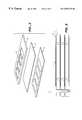
- FIG. 2is an exploded cross-sectional view of a chamber showing the array of gel pads of a preferred embodiment of the invention.
- FIG. 3is an exploded perspective view of the array of biomolecular probes showing the positioning of the gel pads on the substrate of a preferred embodiment of the invention.
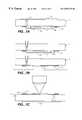
- FIG. 4is an exploded cross-sectional view of a port illustrating the conical shape of the port of a preferred embodiment of the invention.
- FIG. 5is a perspective view of the label layer, the flexible layer and the adhesive layer of a preferred embodiment of the invention.
- FIG. 6is a cross-sectional view of a stack of chambers according to a preferred embodiment.
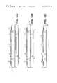
- FIGS. 7A-7Care cross-sectional views of a preferred embodiment of the present invention illustrating the process of analyzing the array after completion of the reaction.
- FIG. 2Ashows the apparatus upon completion of the reaction.
- FIG. 2Billustrates removal of the sample fluid from the chamber such that the flexible layer contacts the array.
- FIG. 2Cillustrates use of a laser scanner to analyze the array.
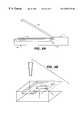
- FIGS. 8A-8Cillustrate a handheld embodiment of the present invention.
- FIG. 8Ais a side view of the hand held scanning system.
- FIG. 8Bis a perspective view of a preferred embodiment comprising a hand-held scanning device illustrating the contact of the flexible layer with the carriage.
- FIG. 8Cis a view of the handheld system illustrating the lid containing the display unit.
- FIGS. 9A-9Eare cross-sectional views of the direct contact fiber optic scanner as shown in FIG. 8 .
- FIGS. 10A-10Care alternate embodiments illustrating the apparatus coupled to a sample preparation chip.
- FIG. 10Aillustrates an embodiment wherein the sample preparation chip is removably positioned against the second surface of the substrate.
- FIG. 10Billustrates an embodiment wherein the sample preparation chip is affixed to the second surface of the substrate.
- FIG. 10Cillustrates an embodiment wherein the sample preparation chip is incorporated into the substrate.
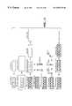
- FIG. 11illustrates the assembly and use of a preferred embodiment of the present invention.
- the present inventionprovides an apparatus for performing high-capacity biological reactions on a biochip comprising a substrate having an array of biological binding sites.
- the inventionprovides a hybridization chamber having one or more arrays, preferably comprising arrays consisting of gel pads and most preferably comprising arrays consisting of 3-dimensional polyacrylamide gel pads, wherein nucleic acid hybridization is performed by reacting a biological sample containing a target molecule of interest with a complementary oligonucleotide probe immobilized on the biochip.
- the arrayis an oligonucleotide array comprising at least about 400, more preferably at least about 1000 and most preferably at least about 10,000 oligonucleotide probes.
- the apparatusis most preferably used for nucleic acid hybridization of target nucleic acids in a biological sample, wherein the biological samples include, but are not limited to, nucleic acids, including DNA, genomic DNA, cDNA, and RNA.
- arrayrefers to an ordered spatial arrangement, particularly an arrangement of immobilized biomolecules or polymeric anchoring structures.
- addressable arrayrefers to an array wherein the individual elements have precisely defined x and y coordinates, so that a given element can be pinpointed.
- biomolecular proberefers to a biomolecule used to detect a complementary biomolecule. Examples include antigens which detect antibodies, oligonucleotides which detect complimentary oligonucleotides, and ligands which detect receptors. Such probes are preferably immobilized on a substrate.
- oligonucleotide proberefer to a nucleic acid sequence used to detect the presence of a complementary target sequence by hybridization with the target sequence.
- biochiprefers to an array of biomolecular probes, preferably oligonucleotide probes, immobilized on a substrate.
- Biochipsencompass substrates containing arrays or microarrays, preferably ordered arrays and most preferably ordered, addressable arrays, of biological molecules that comprise one member of a biological binding pair.
- arraysare oligonucleotide arrays comprising a nucleotide sequence that is complementary to at least one sequence expected to be present in a biological sample.
- peptides or other small moleculescan be arrayed in such biochips for performing immunological analysis (wherein the arrayed molecules are antigens) or assaying biological receptors (wherein the arrayed molecules are ligands, agonists or antagonists of said receptors).
- biochipsOne key feature of biochips is the manner in which the arrayed biomolecules are attached to the surface of the biochip. Conventionally such procedures involve multiple reaction steps, often requiring chemical modification of the solid support itself. Even in embodiments comprising absorption matrices, such as hydrogels, present on a solid support, chemical modification of the gel polymer is necessary to provide a chemical functionality capable forming a covalent bond with the biomolecule. The efficiency of the attachment chemistry and strength of the chemical bonds formed are critical to the fabrication and ultimate performance of the micro array.
- Polyacrylamide hydrogels and gel padsare used as binding layers to adhere to surfaces biological molecules including, but not limited to, proteins, peptides, oligonucleotides, polynucleotides, and larger nucleic acid fragments.
- the gel pads comprising biochips for use with the apparatus of the present inventionare conveniently produced as thin sheets or slabs, typically by depositing a solution of acrylamide monomer, a crosslinker such methylene bisacrylamide, and a catalyst such as N,N,N′,N′-tetramethylethylendiamine (TEMED) and an initiator such as ammonium persulfate for chemical polymerization, or 2,2-dimethoxy-2-phenyl-acetophone (DMPAP) for photopolymerization, in between two glass surfaces (e.g., glass plates or microscope slides) using a spacer to obtain the desired thickness of polyacrylamide gel.
- TEMEDN,N,N′,N′-tetramethylethylendiamine
- the acrylamide monomer and crosslinkerare prepared in one solution of about 4-5% acrylamide (having an acrylamide/bisacrylamide ratio of 19/1) in water/glycerol, with a nominal amount of initiator added.
- the solutionis polymerized and crosslinked either by ultraviolet (UV) radiation (e.g., 254 nm for at least about 15 minutes, or other appropriate UV conditions, collectively termed “photopolymerization”), or by thermal initiation at elevated temperature (e.g., typically at about 40° C.).
- UV radiationultraviolet
- photopolymerizationthermal initiation at elevated temperature
- the top glass slideis removed from the surface to uncover the gel.
- the pore size (and hence the “sieving properties”) of the gelis controlled by changing the amount of crosslinker and the percent solids in the monomer solution.
- the pore sizealso can be controlled by changing the polymerization temperature.
- the acrylamide solutiontypically is imaged through a mask during the UV polymerization/crosslinking step.
- the top glass slideis removed after polymerization, and the unpolymerized monomer is washed away (developed) with water, leaving a fine feature pattern of polyacrylamide hydrogel, which is used to produce the crosslinked polyacrylamide hydrogel pads.
- lightcan be applied to discrete locations on the surface of a polyacrylamide hydrogel to activate these specified regions for the attachment of an oligonucleotide, an antibody, an antigen, a hormone, hormone receptor, a ligand or a polysaccharide on the surface (e.g., a polyacrylamide hydrogel surface) of a solid support (see, for example, International Application, Publication No. WO 91/07087, incorporated by reference).
- biomoleculessuch as oligonucleotides
- oligonucleotidesare covalently attached by forming an amide, ester or disulfide bond between the biomolecule and a derivatized polymer comprising the cognate chemical group.
- Covalent attachment of the biomolecule to the polymeris usually performed after polymerization and chemical cross-linking of the polymer is completed Alternatively, oligonucleotides bearing 5′-terminal acrylamide modifications can be used that efficiently copolymerize with acrylamide monomers to form DNA-containing polyacrylamide copolymers (Rehman et al., 1999, Nucleic Acids Research 27: 649-655).
- the inventionprovides a hybridization chamber 10 comprising a biochip, which comprises a substrate 11 having a first surface 12 and a second surface 13 opposite thereto, and a flexible layer 16 affixed to the first substrate surface 12 by an adhesive layer 15 .
- a biochipwhich comprises a substrate 11 having a first surface 12 and a second surface 13 opposite thereto, and a flexible layer 16 affixed to the first substrate surface 12 by an adhesive layer 15 .
- On the first surface 12is an area 14 bounded by adhesive layer 15 an completely covered by flexible layer 16 .
- Flexible layer 16 , adhesive layer 15 , and first substrate surface 12further define a volume 25 .
- the ratio of volume 25 to area 14is preferably from about 0.025 ⁇ L/mm 2 to about 0.25 ⁇ L/mm 2 , more preferably from about 0.1 ⁇ L/mm 2 to about 0.25 ⁇ L/mm 2 , and most preferably from about 0.1 ⁇ L/mm 2 to about 0.2 ⁇ L/mm 2 .
- an array 17 of biomoleculeswhich is preferably affixed to first substrate surface 12 .
- Array 17most preferably further comprises gel pads 22 .
- FIG. 2provides an exploded cross-sectional view of a portion of array 17 illustrating the gel pads 22 .
- Each gel structure 22is preferably cylindrical, most preferably having about a 113 micron diameter and about a 25 micron thickness. The distance between each site within each array 17 is most preferably about 300 microns.
- a layer of a water-soluble compound 28 having a melting point of about 30 to about 60° C., more preferably of about 35 to about 50° C., and most preferably of about 35 to about 45° C.is deposited in volume 25 bounded by first substrate surface 12 , flexible layer 16 , and adhesive layer 15 .
- the water-soluble compoundis biocompatible, does not stick to flexible layer 16 , and serves to prevent mechanical damage to gel pads 22 .
- the compoundis polyethylene glycol, most preferably polyethylene glycol 600.
- the compound 28is deposited so that the entire volume 25 , with the exception of that portion of volume 25 occupied by array 17 , comprises compound 28 .
- Array 17can be positioned on surface 12 by providing markings, most preferably holes or pits in surface 12 , that act as fiducials or reference points on surface 12 for accurate placement of array 17 .
- the presence of said fiducialsis particularly advantageous in embodiments comprising a multiplicity of arrays 17 in one or a multiplicity of areas 14 on surface 12 , wherein accurate placement of said arrays is required for proper spacing and orientation of the arrays on the hybridization chamber.
- Substrate 11further comprises a first port 19 that transverses the substrate from the first surface 12 to the second surface 13 and forms first and second openings 29 and 30 on said first and second surfaces, respectively.
- the first port 19serves as an input port and is positioned in substrate 11 so that the first opening 29 is provided within the area 14 bounded by adhesive layer 15 on first surface 12 .
- substrate 11further comprises a second port 20 that transverses the substrate from first surface 12 to second surface 13 and forms first and second openings 31 and 32 on said first and second surfaces, respectively.
- Second port 20serves as an outlet port and is positioned in substrate 11 so that the first opening 31 opens within area 14 bounded by the adhesive layer 15 on the first surface 12 .
- the second openings of ports 19 and 20are covered with a removable and replaceable cover 21 .
- replaceable cover 21is a stopper, a gasket, or tape, most preferably foil tape.
- Input and output ports 19 and 20are preferably shaped to accept a plastic pipette tip, most preferably a 10 ⁇ L pipette tip or a 200 ⁇ L pipette tip.
- input and output ports 19 and 20are generally in the shape of a truncated cone, as shown in FIG. 4, wherein the end of the cone having the smallest diameter forms the first opening of each port, 29 and 31 respectively, and the end of the cone having the largest diameter forms the second opening of each port, 30 and 32 respectively. This shape creates a seal between the pipette tip and the port, enhances visibility of the port for operator accuracy and prevents protrusion of the pipette tip into volume 25 .
- each portpreferably has a diameter on the second surface of from about 1.0 mm to about 2.0 mm, and a diameter on the first surface of from about 0.3 mm to about 0.6 mm.
- the conical walls of ports 19 and 20form an angle 54 with the second substrate surface 13 , which is preferably less than 90°.
- angle 54is less than or equal to the contact angle 55 of the solutions used for hybridization.
- angle 54is equal to contact angle 55 such that the surface of the fluid in the port is flat. For aqueous solutions, this angle is about 60°.
- This geometric arrangementprovides a port that tends not to leak and wicks fluid into volume 25 so that the second substrate surface 13 is dry when replaceable cover 21 is applied.
- Substrate 11is fabricated from any solid supporting substance, including but not limited to plastics, metals, ceramics, and glasses. Most preferably, substrate 11 is made from silicon or glass (for accuracy and stiffness), molded plastics (which reduce cost of manufacture and thermal inertia), or ceramics (for the incorporation of microfluidic elements including integrated heating elements). Most preferably, the substrate is glass.
- Adhesive layer 15is prepared using an adhesive suitable for forming a water-tight bond between substrate 11 and flexible layer 16 , including, but not limited to, high temperature acrylics, rubber-based adhesives, and silicone-based adhesives.
- the shape of adhesive layer 15is configured to contain array 17 .
- Adhesive layer 15can be deposited on first substrate surface 12 in a pattern to produce area 14 in any desired shape, and is most preferably deposited to define an ellipsoid area 14 .
- Adhesive layer 15can be deposited using inkjet printing or offset printing methods, or by die cutting the desired shapes from a sheet of adhesive material.
- first surface 12can be covered with adhesive and portions of the substrate which are not desired to retain adhesive properties can be hardened preferentially, for example, by ultraviolet curing.
- portions retaining adhesive propertiescan be defined using a mask and thereby retain adhesive properties necessary to affix flexible layer 16 to surface 12 .
- the adhesive materialis preferably a double sided adhesive tape, and more preferably a double sided adhesive tape having no carrier.
- Adhesive layer 15is most preferably set down in a layer between 1 and 100 ⁇ m thick, more preferably between 25 and 50 ⁇ m thick, and most preferably about 50 ⁇ m thick.
- Flexible layer 16is made of any flexible solid substance, including but not limited to plastics, including polypropylene, polyethylene, and polyvinylidene chloride (sold commercially as Saran® wrap) plastics, rubbers, including silicone rubbers, high temperature polyesters, and porous Teflon®.
- Flexible layer 16is preferably biocompatible and preferably has low permeability in order to prevent evaporation of water from the volume contained between the flexible layer and the substrate.
- Flexible layer 16also preferably is optically clear and should be able to withstand temperatures of between 50 and 95° C. for a period of between 8 and 12 hours without shrinkage.
- the flexible layeris a gas permeable membrane.
- Flexible layer 16preferably covers an area of from about 5 mm 2 to about 1400 mm 2 , more preferably from about 5 mm 2 to about 600 mm 2 , and most preferably from about 100 mm 2 to about 600 mm 2 .
- the inventionfurther comprises a label layer 57 which is die cut in the same manner as the adhesive to form windows 58 that correspond in location to areas 14 on first substrate surface 12 .
- the label layeris preferably a thick film having a layer of adhesive, and most preferably is an Avery laser label.
- the label layeris applied to the outer surface of the flexible layer, preferably by vacuum lamination.
- Array 17 contained in area 14 on first substrate surface 12is covered with a water-soluble compound 28 , which protects and seals the biochip prior to use and prevents degradation or other damage to the array.
- Any water-soluble compound 28 having a melting point of about 30 to about 60° C., more preferably of about 35 to about 50° C., and most preferably of about 35 to about 45° C.is advantageously used in filling volume 25 between array 17 and flexible layer 16 .
- the compoundis polyethylene glycol, most preferably polyethylene glycol 600. It is a particularly preferred feature of hybridization chamber 10 of the invention that water-soluble compound 28 fills the entirety of the volume 25 and more preferably also fills at least a portion of input port 19 .
- Ports and holescan be produced in substrate 11 by diamond drilling in glass embodiments of substrate 11 or by stamping or molding in plastic embodiments thereof. This facilitates standardization of the hybridization chamber dimensions, for example, by producing substrates where the first and second ports 19 and 20 are produced in a single operation. Both the substrate 11 and the removable cover 21 can be set down as strips or large sheets, and can be rolled to avoid trapping air bubbles. Flexible layer 16 can be applied by vacuum lamination to avoid trapping air, or can be deposited by spinning or flowing liquid plastic over substrate 11 after treatment with adhesive 15 and water-soluble compound 28 , followed by curing the flexible layer in place. Individual hybridization chambers 10 can be produced in stacks using, for example, a diamond saw as shown in FIG. 6 .
- FIG. 6illustrates a preferred arrangement for manufacturing hybridization chamber 10 , wherein alternating layers of flexible layer 16 , adhesive layer 15 , uncut substrate 11 , and removable cover 21 are laid down, and hybridization chambers are produced by cutting the stacked layers, for example, with a diamond saw or any appropriate manufacturing tool.
- the sealed volumes 25protect the arrays 17 from debris produced during the cutting process.
- hybridization chamber 10 of the inventionencompass a multiplicity of arrays 17 confined in a multiplicity of areas 14 underneath flexible layer 16 , each area comprising an array 17 and being supplied with first port 19 and, optionally, second port 20 .
- adhesive layer 15is deposited on first substrate surface 12 in a pattern that defines each of areas 14 , and flexible layer 16 is applied to adhesive layer 15 to encompass areas 14 on said surface.
- hybridization chamber 10is produced containing array 17 or a multiplicity of arrays 17 as disclosed herein, wherein the chamber is provided ready-to-use by the addition of hybridization fluid 26 comprising one or a multiplicity of target molecules.
- hybridization chamber 10is provided without array 17 , and allows for insertion thereof by a user. In these embodiments, at least one edge of flexible layer 16 is not adhered to first substrate surface 12 .
- an amount of a hybridization fluid 26is added to the hybridization chamber through first port 19 .
- volume 25is most preferably heated to a temperature greater than or equal to the melting temperature of water-soluble compound 28 .
- hybridization fluid 26can be added to the chamber and mixed with the water-soluble compound, as shown in FIG. 1 B.
- water-soluble compound 28does not affect hybridization in the chamber. More preferably, the amount of compound 28 is chosen such that hybridization efficiency is improved when compound 28 is mixed with sample fluid 26 .
- the hybridization fluidis preferably introduced into the chamber after compound 28 is melted, and then the fluid is cycled into and out of the chamber using, most preferably, a pipette, until fluid 26 and compound 28 are fully mixed, and the hybridization fluid evenly distributed over the surface of array 17 , or mixed into gel pads 22 comprising certain embodiments of said arrays.
- hybridization fluid 26is evenly distributed over the surface of array 17 , or mixed into gel pads 22 by physically manipulating flexible layer 16 , as more fully described below.
- hybridization fluid 26is removed after hybridization is completed, as shown in FIG. 7, and array 17 is washed by the cycling a sufficient volume of a wash solution 27 into and out of the chamber, most preferably using a pipette.
- the hybridization fluidis preferably introduced into the chamber after compound 28 is melted, and then the fluid is cycled into and out of the chamber using, most preferably, at least one pipette, until fluid 26 and compound 28 are fully mixed, and the hybridization fluid evenly distributed over the surface of array 17 , or mixed into gel pads 22 comprising certain embodiments of said biochips. Hybridization is then performed by incubating the chamber for a time and at a temperature sufficient for hybridization to be accomplished.
- Hybridization fluid 26is removed after hybridization has been completed using outlet port 20 , and the biochip washed by the addition and cycling of a sufficient volume of a wash solution 27 into and out of the chamber, most preferably using a pipette.
- the wash solutioncan also be continuously provided by addition through the input port and removal through the output port.
- the biochip containing the hybridized arrayis removed from the chamber for development or further manipulations as required.
- the biochip containing the hybridized arrayis analyzed in situ as described below.
- FIG. 1Billustrates an advantageous embodiment of hybridization chamber 10 of the invention, further comprising a heating element 33 .
- heating element 33has a heating surface 34 adapted to the shape of hybridization chamber 10 to substantially cover the area 14 under flexible layer 16 .
- Heating element 33is any suitable heating means, including but not limited to resistance heaters, thermoelectric heaters, or microwave absorbing heaters.
- the hybridization chamber 10 of the inventionalso advantageously comprises a thermocouple 35 or other temperature-sensing or measuring element to measure the temperature of hybridization fluid 26 or chamber 10 .
- These temperature-sensing elementsadvantageously are coupled with heating element 33 to control hybridization fluid 26 and wash solution 27 temperature, and can be used to calibrate other elements, such as scanning devices 36 as described below that may be sensitive to temperature.
- positive hybridizationis detected visually, i.e., by the production of a dye or other material that reflects visible light at sites on biochip 18 where hybridization has occurred.
- the dye or other materialis most preferably produced enzymatically, for example, using a hybridization-specific immunological reagent such as an antibody linked to an enzyme that catalyzes the production of the dye.
- Visual inspectioncan be used to detect sites of positive, hybridization. More preferably, the biochip containing the hybridized array is scanned using scanner 36 as disclosed more fully below.
- Positive hybridization on biochip 18most preferably is detected by fluorescence using labeled target molecules in a biological sample, or by including intercalating dyes in the hybridization fluid 26 that fluoresce when bound by a hybridized DNA duplex and illuminated by light at a particular wavelength.
- Suitable intercalating dyesinclude, but are not limited to, ethidium bromide, Hoechst DAPI, and Alexa Fluor dyes.
- Suitable fluorescence labelsinclude, but are not limited to, fluorescein, rhodamine, propidium iodide, and Cy3 and Cy5 (Amersham), that can be incorporated into target molecules, for example, in vitro amplified fragments using labeled oligonucleotide primers.
- FIGS. 8A-8Cillustrate an embodiment of the invention comprising a scanner 36 , which is advantageously positioned over (or beneath) flexible layer 16 and moves from one end of area 14 to the opposite end, sequentially illuminating area 14 and array 17 positioned thereupon.
- a scanner 36Prior to analysis of the hybridized array, all fluid is removed from volume 25 such that flexible layer 16 is in contact with array 17 .
- Scanner 36then excites the fluorescent dye, preferably with short wavelength light, most preferably light with a wavelength between 250 nm and 600 nm. Scanner 36 then collects the emitted light from a specific area. The amount of light emitted is then used to determine the amount of fluorescent dye present in the area, and hence the amount of labeled target.
- FIGS. 9A through 9EParticular embodiments of scanners and scanning devices 36 are shown in FIGS. 9A through 9E. It is a particularly advantageous feature of hybridization chamber 10 that flexible layer 16 is translucent to suitable wavelengths of light, including light in the ultraviolet and visible portion of the spectrum. An additional advantageous feature of hybridization chamber 10 is that flexible layer 16 , which is very thin, is immediately adjacent to and in contact with biochip 18 after hybridization fluid 26 or wash fluid 27 is removed from the chamber. This combination of features reduces or eliminates free surface reflections, internal reflection of illumination from the scanner, and dispersion or scattering of illuminating light, thereby optimizing the amount of incident light that illuminates array 17 . This arrangement is also more economical than in existing apparatus as it minimizes the need for highly polished, low scattering surfaces or complex or expensive lenses, and eliminates problems associated with focus and depth-of-field in more complex optical detectors.
- a light pipe 37contacts the surface of flexible layer 16 which is immediately adjacent to and in contact with the surface of array 17 , as shown in FIG. 9 B.
- both illuminating and emitted lightare conveyed and collected by light pipe 37 .
- the pipeis designed to be slightly flexible so as to adapt to the contoured surface of flexible layer 16 .
- Light pipe 37contacts flexible layer 16 which contacts array 17 , thereby permitting contacts free of surface reflections even under circumstances where array 17 or light pipe 37 has localized variations in height.
- light pipe 37has a larger surface area than array 17 , so that the maximum amount of illuminating light is delivered to array 17 , and the maximum amount of emitted light from array 17 is collected by light pipe 37 .
- a further advantage of light pipe 37is that it enables detection of bubbles formed in hybridization fluid 26 or wash buffer 27 , which detection can be used as a signal for roller 40 to address flexible layer 16 to remove such bubbles. Removing bubbles in hybridization fluid 26 or wash buffer 27 reduces the frequency of non-specific binding and artifactual signals detected by scanner 36 .
- the area 14 defined by adhesive layer 15further comprises a reflective layer 38 that substantially covers the entirety of the area 14 and is positioned between array 17 and the first substrate surface 12 .
- reflective layer 38comprises aluminum, gold, silver, or platinum.
- the amount of the light signal reflected or transmitted to the light-detecting portion of scanner 36is increased up to four-fold.
- reflective layer 38is a metal film resistor or an RF induction heater. In these embodiments, reflective 38 layer can heat the slide without requiring additional heating elements 33 . This is a particularly desirable feature in hand-held embodiments of the hybridization chamber 10 of the invention.
- passivation layer 39is a layer of parylene a few microns thick that is applied by evaporation.
- the amount of illumination required, and hence the amount of power needed to operate scanner 36is reduced in these embodiments, which are particularly suited to battery-operated embodiments such as hand-held devices to improve useful battery life.
- passivation layer 39reduces artifactual signals in the light emission data by obscuring objects that it covers.
- Hybridization chamber 10is preferably supplied with a roller 40 in removable contact with flexible layer 16 and that can be moved longitudinally across areas 14 on first substrate surface 12 .
- the surface of roller 40comprises a textured pattern 41 , most preferably a spiral pattern, that permits the roller to efficiently mix hybridization fluid and wash solution across area 14 and array 17 .
- FIG. 9 EOne advantageous arrangement of roller 40 and hybridization chamber 10 is shown in FIG. 9 E.
- roller 40can be advantageously connected to a movable arm 42 that can be positioned to place roller 40 in contact with flexible layer 16 when in a first position, and can be moved to a second position in which roller 40 is not in contact with flexible layer 16 .
- movable arm 42has a pivot point 44 and movement about said pivot point is preferably controlled by a solenoid.
- either roller 40 or hybridization chamber 10 , or bothare movable in a longitudinal direction to enable roller 40 to mix hybridization fluid 26 or wash solution 27 inside volume 25 bounded by flexible layer 16 , adhesive layer 15 , and first substrate surface 12 in area 14 containing array 17 .
- roller 40is positioned to move longitudinally across each of the multiplicity of areas 14 to mix hybridization fluid 26 or wash solution 27 in each of the volumes 25 containing arrays 17 .
- a sample preparation chip 45comprising a port 46 , as shown in FIGS. 10A through 10C, can be attached to hybridization chamber 10 .
- port 46 in sample preparation chip 45is aligned with first port 19 in hybridization chamber 10 to permit efficient transfer of sample to volume 25 .
- Additional fiducial referencescan be used to accurately align hybridization chamber 10 and sample preparation chip 45 . Since access to first port 19 is through second substrate surface 13 , the array can be scanned without interference from the attached sample preparation chip.
- sample preparation chip 45may be bound to second substrate surface 13 (FIG. 10B) or formed as an integral part of substrate 11 (FIG. 10 C).
- hybridization chamber 10 of the inventionis a hand-held embodiment as shown in FIGS. 8A-8C, further comprising a scanner 36 .
- hand-held device 47comprises a base 48 , a lid 49 and a carriage 50 embodying roller 40 , scanner 36 , heating element 33 and thermocouple 35 .
- Carriage 50is illustrated in FIG. 9 A.
- Device 47comprises a compartment 51 for positioning hybridization chamber 10 in proximity to carriage 50 .
- Carriage 50is provided with moving means for moving roller 40 , scanner 36 and heating element 33 relative to hybridization chamber 10 as required for operation as described above.
- Carriage 50 and lid 49are arranged to permit a user to introduce and remove hybridization fluid 26 and wash solution 27 into the chamber through first port 19 and second port 20 as required.
- device 47further comprises fluidic connections 52 to each of the first and second ports to provide for sample introduction and array washing after hybridization of the sample thereto.
- Device 47is most preferably operated by battery, although AC adapters are also advantageously encompassed by the description of the device herein.
- lid 49further comprises a display 56 for displaying the results of the analysis.
- FIG. 11The process of assembling a chamber according to the present invention is illustrated in FIG. 11 .
- a die cutterwas used to cut four ellipsoidal holes in a layer of 502FL ultra-clean laminating adhesive film (3M).
- a similar patternwas punched into an Avery laser label 5663 for use as a frame and label layer.
- a sheet of polyvinylidene chloride filmwas stretched over a stainless steel frame and annealed for 30 minutes at 100° C.
- the Avery labelwas applied to one side of the polyvinylidine chloride film by vacuum laminating the label in a vacuum lamination press.
- a vacuum of 15 psiwas applied for 30 seconds, and mechanical pressure of 15 psi was maintained for 1 minute after release of the vacuum.
- the adhesivewas then applied to the opposite side of the polyvinylidene chloride film using the same process as for the label.
- the adhesive coated filmwas then applied to a glass slide which had previously been prepared.
- the arrays of oligonucleotide probes and gel padswere positioned on the glass slide using standard methods. Ports were drilled into the slide using a diamond drill.
- a vacuum lamination presswas used to affix the polyvinylidene chloride film to the slide. A vacuum of 15 psi was maintained for 1 minute, and then mechanical pressure of 15 psi was maintained for an additional minute.
- the individual chamberswere then filled with polyethylene glycol 600 using a 10 ⁇ l pipette tip.
- a layer of 3M 7350 polyester tapewas then applied to the slide to seal off the ports.
Landscapes
- Chemical & Material Sciences (AREA)
- Health & Medical Sciences (AREA)
- Analytical Chemistry (AREA)
- General Health & Medical Sciences (AREA)
- Hematology (AREA)
- Clinical Laboratory Science (AREA)
- Chemical Kinetics & Catalysis (AREA)
- Dispersion Chemistry (AREA)
- Apparatus Associated With Microorganisms And Enzymes (AREA)
- Measuring Or Testing Involving Enzymes Or Micro-Organisms (AREA)
Abstract
Description
Claims (23)
Priority Applications (10)
| Application Number | Priority Date | Filing Date | Title |
|---|---|---|---|
| US09/464,490US6589778B1 (en) | 1999-12-15 | 1999-12-15 | Method and apparatus for performing biological reactions on a substrate surface |
| US09/492,013US6569674B1 (en) | 1999-12-15 | 2000-01-26 | Method and apparatus for performing biological reactions on a substrate surface |
| EP00991410AEP1242819A2 (en) | 1999-12-15 | 2000-12-15 | Apparatus for performing biological reactions |
| JP2001545592AJP2003517156A (en) | 1999-12-15 | 2000-12-15 | Compositions and methods for performing biological reactions |
| PCT/US2000/034145WO2001044515A2 (en) | 1999-12-15 | 2000-12-15 | Apparatus for performing biological reactions |
| CA002394275ACA2394275A1 (en) | 1999-12-15 | 2000-12-15 | Apparatus for performing biological reactions |
| AU32641/01AAU778696B2 (en) | 1999-12-15 | 2000-12-15 | Compositions and methods for performing biological reactions |
| US09/861,171US6875619B2 (en) | 1999-11-12 | 2001-05-17 | Microfluidic devices comprising biochannels |
| US10/394,484US20030190744A1 (en) | 1999-12-15 | 2003-03-20 | Method and apparatus for performing biological reactions on a substrate surface |
| US10/430,808US20040018523A1 (en) | 1999-12-15 | 2003-05-05 | Method and apparatus for performing biological reactions on a substrate surface |
Applications Claiming Priority (1)
| Application Number | Priority Date | Filing Date | Title |
|---|---|---|---|
| US09/464,490US6589778B1 (en) | 1999-12-15 | 1999-12-15 | Method and apparatus for performing biological reactions on a substrate surface |
Related Child Applications (3)
| Application Number | Title | Priority Date | Filing Date |
|---|---|---|---|
| US09/492,013Continuation-In-PartUS6569674B1 (en) | 1999-11-12 | 2000-01-26 | Method and apparatus for performing biological reactions on a substrate surface |
| US09/861,171Continuation-In-PartUS6875619B2 (en) | 1999-11-12 | 2001-05-17 | Microfluidic devices comprising biochannels |
| US10/430,808ContinuationUS20040018523A1 (en) | 1999-12-15 | 2003-05-05 | Method and apparatus for performing biological reactions on a substrate surface |
Publications (1)
| Publication Number | Publication Date |
|---|---|
| US6589778B1true US6589778B1 (en) | 2003-07-08 |
Family
ID=23844150
Family Applications (2)
| Application Number | Title | Priority Date | Filing Date |
|---|---|---|---|
| US09/464,490Expired - Fee RelatedUS6589778B1 (en) | 1999-11-12 | 1999-12-15 | Method and apparatus for performing biological reactions on a substrate surface |
| US10/430,808AbandonedUS20040018523A1 (en) | 1999-12-15 | 2003-05-05 | Method and apparatus for performing biological reactions on a substrate surface |
Family Applications After (1)
| Application Number | Title | Priority Date | Filing Date |
|---|---|---|---|
| US10/430,808AbandonedUS20040018523A1 (en) | 1999-12-15 | 2003-05-05 | Method and apparatus for performing biological reactions on a substrate surface |
Country Status (1)
| Country | Link |
|---|---|
| US (2) | US6589778B1 (en) |
Cited By (15)
| Publication number | Priority date | Publication date | Assignee | Title |
|---|---|---|---|---|
| US20030064507A1 (en)* | 2001-07-26 | 2003-04-03 | Sean Gallagher | System and methods for mixing within a microfluidic device |
| US20030068253A1 (en)* | 2001-01-31 | 2003-04-10 | Bass Jay K. | Automation-optimized microarray package |
| US20030134410A1 (en)* | 2002-11-14 | 2003-07-17 | Silva Robin M. | Compositions and methods for performing biological reactions |
| US20030152957A1 (en)* | 2002-02-12 | 2003-08-14 | Olympus Optical Co., Ltd. | Probe-immobilized reaction arrays |
| US20030157503A1 (en)* | 2003-04-04 | 2003-08-21 | Mcgarry Mark W | Compositions and methods for performing biological reactions |
| US20040018523A1 (en)* | 1999-12-15 | 2004-01-29 | Amersham Biosciences Ab | Method and apparatus for performing biological reactions on a substrate surface |
| US20050170401A1 (en)* | 2004-01-29 | 2005-08-04 | Canon Kabushiki Kaisha | Hybridization apparatus and method |
| US20060176492A1 (en)* | 2005-02-10 | 2006-08-10 | Tsung-Kai Chuang | Positioning method for biochip |
| US20070009914A1 (en)* | 2005-07-07 | 2007-01-11 | Wallace Robert B | Labeled complimentary oligonucleotides to detect oligonucleotide-linked ligands |
| US7297553B2 (en) | 2002-05-28 | 2007-11-20 | Nanosphere, Inc. | Method for attachment of silylated molecules to glass surfaces |
| US7687437B2 (en) | 2001-07-13 | 2010-03-30 | Nanosphere, Inc. | Method for immobilizing molecules onto surfaces |
| US20120111535A1 (en)* | 2010-10-28 | 2012-05-10 | Alstom Technology Ltd. | Orifice plate for controlling solids flow, methods of use thereof and articles comprising the same |
| US9617087B2 (en) | 2010-10-28 | 2017-04-11 | General Electric Technology Gmbh | Control valve and control valve system for controlling solids flow, methods of manufacture thereof and articles comprising the same |
| NL2019044B1 (en)* | 2017-05-11 | 2018-11-15 | Illumina Inc | Protective surface coatings for flow cells |
| CN113070113A (en)* | 2021-06-03 | 2021-07-06 | 成都齐碳科技有限公司 | Chip structure, film forming method, nanopore sequencing device and application |
Families Citing this family (21)
| Publication number | Priority date | Publication date | Assignee | Title |
|---|---|---|---|---|
| DE102004022263A1 (en)* | 2004-05-06 | 2005-12-15 | Clondiag Chip Technologies Gmbh | Apparatus and method for detecting molecular interactions |
| DE102005052713A1 (en) | 2005-11-04 | 2007-05-16 | Clondiag Chip Tech Gmbh | Apparatus and method for detecting molecular interactions |
| US8916348B2 (en)* | 2004-05-06 | 2014-12-23 | Clondiag Gmbh | Method and device for the detection of molecular interactions |
| EP1824601B1 (en)* | 2004-10-18 | 2016-12-28 | Life Technologies Corporation | A device including a dissolvable structure for flow control |
| US10753927B2 (en) | 2006-09-22 | 2020-08-25 | ALERE TECHNOLOGIES GmbH | Methods for detecting an analyte |
| EP2078189B1 (en)* | 2006-10-20 | 2012-10-10 | Clondiag GmbH | Assay devices and methods for the detection of analytes |
| US9097671B2 (en) | 2006-11-22 | 2015-08-04 | Clondiag Gmbh | Assays |
| AU2007324494B2 (en)* | 2006-11-22 | 2013-08-22 | Clondiag Gmbh | Methods for optically detecting multiple analytes in a liquid sample with a compressible microfluidic device |
| US7778512B2 (en)* | 2007-08-28 | 2010-08-17 | Scenterra, Inc. | Light-pipe array system |
| US9321051B2 (en) | 2009-12-22 | 2016-04-26 | Samsung Electronics Co., Ltd. | Microfluidic device and method of manufacturing the same |
| KR20110072275A (en)* | 2009-12-22 | 2011-06-29 | 삼성전자주식회사 | Microfluidic device and its manufacturing method |
| DE102010035104A1 (en)* | 2010-08-23 | 2012-04-05 | Euroimmun Medizinische Labordiagnostika Ag | Automatic focusing apparatus and method for low luminance microscopy microscopy |
| US10114020B2 (en)* | 2010-10-11 | 2018-10-30 | Mbio Diagnostics, Inc. | System and device for analyzing a fluidic sample |
| WO2014070235A1 (en) | 2012-10-29 | 2014-05-08 | Mbio Diagnostics, Inc. | Biological particle identification system, cartridge and associated methods |
| CN103149662B (en)* | 2013-02-28 | 2015-01-21 | 海信集团有限公司 | Reflecting-mirror bonding method and reflecting-mirror bonding device |
| GB2554377A (en)* | 2016-09-23 | 2018-04-04 | Dnanudge Ltd | Method and apparatus for analysing a biological sample |
| US10467679B1 (en) | 2019-04-15 | 2019-11-05 | Dnanudge Limited | Product recommendation device and method |
| US10811140B2 (en) | 2019-03-19 | 2020-10-20 | Dnanudge Limited | Secure set-up of genetic related user account |
| US10699806B1 (en) | 2019-04-15 | 2020-06-30 | Dnanudge Limited | Monitoring system, wearable monitoring device and method |
| JP2022049382A (en)* | 2020-09-16 | 2022-03-29 | 株式会社エンプラス | Fluid handling device and manufacturing method of fluid handling device |
| WO2022119744A1 (en) | 2020-12-01 | 2022-06-09 | Illumina, Inc. | Well assemblies and related methods |
Citations (38)
| Publication number | Priority date | Publication date | Assignee | Title |
|---|---|---|---|---|
| US4908319A (en) | 1988-03-16 | 1990-03-13 | Smyczek Peter J | Laboratory apparatus |
| WO1991007087A1 (en) | 1989-11-13 | 1991-05-30 | Affymax Technologies N.V. | Spatially-addressable immobilization of anti-ligands on surfaces |
| US5038852A (en) | 1986-02-25 | 1991-08-13 | Cetus Corporation | Apparatus and method for performing automated amplification of nucleic acid sequences and assays using heating and cooling steps |
| US5100775A (en) | 1988-03-16 | 1992-03-31 | Smyczek Peter J | Method for conducting nucleic acid hybridization in chamber with precise fluid delivery |
| US5143854A (en) | 1989-06-07 | 1992-09-01 | Affymax Technologies N.V. | Large scale photolithographic solid phase synthesis of polypeptides and receptor binding screening thereof |
| US5169697A (en)* | 1990-05-25 | 1992-12-08 | Kappler Safety Group | Seaming tape for composite chemical barrier fabrics and method of forming bonded seams |
| US5360741A (en) | 1992-09-29 | 1994-11-01 | Triangle Biomedical Sciences, Inc. | DNA hybridization incubator |
| US5474796A (en) | 1991-09-04 | 1995-12-12 | Protogene Laboratories, Inc. | Method and apparatus for conducting an array of chemical reactions on a support surface |
| US5492806A (en) | 1987-04-01 | 1996-02-20 | Hyseq, Inc. | Method of determining an ordered sequence of subfragments of a nucleic acid fragment by hybridization of oligonucleotide probes |
| US5525464A (en) | 1987-04-01 | 1996-06-11 | Hyseq, Inc. | Method of sequencing by hybridization of oligonucleotide probes |
| US5541061A (en) | 1992-04-29 | 1996-07-30 | Affymax Technologies N.V. | Methods for screening factorial chemical libraries |
| US5545531A (en) | 1995-06-07 | 1996-08-13 | Affymax Technologies N.V. | Methods for making a device for concurrently processing multiple biological chip assays |
| US5571639A (en) | 1994-05-24 | 1996-11-05 | Affymax Technologies N.V. | Computer-aided engineering system for design of sequence arrays and lithographic masks |
| US5578832A (en) | 1994-09-02 | 1996-11-26 | Affymetrix, Inc. | Method and apparatus for imaging a sample on a device |
| US5580717A (en) | 1990-05-01 | 1996-12-03 | Affymax Technologies N.V. | Recombinant library screening methods |
| US5599695A (en) | 1995-02-27 | 1997-02-04 | Affymetrix, Inc. | Printing molecular library arrays using deprotection agents solely in the vapor phase |
| WO1997010056A2 (en) | 1995-09-12 | 1997-03-20 | Becton Dickinson And Company | Device and method for dna amplification and assay |
| US5631734A (en) | 1994-02-10 | 1997-05-20 | Affymetrix, Inc. | Method and apparatus for detection of fluorescently labeled materials |
| US5733729A (en) | 1995-09-14 | 1998-03-31 | Affymetrix, Inc. | Computer-aided probability base calling for arrays of nucleic acid probes on chips |
| US5744305A (en) | 1989-06-07 | 1998-04-28 | Affymetrix, Inc. | Arrays of materials attached to a substrate |
| US5770456A (en) | 1989-06-07 | 1998-06-23 | Affymetrix, Inc. | Cyclic nucleic acid and polypeptide arrays |
| US5786439A (en)* | 1996-10-24 | 1998-07-28 | Minimed Inc. | Hydrophilic, swellable coatings for biosensors |
| US5837832A (en) | 1993-06-25 | 1998-11-17 | Affymetrix, Inc. | Arrays of nucleic acid probes on biological chips |
| US5843655A (en) | 1995-09-18 | 1998-12-01 | Affymetrix, Inc. | Methods for testing oligonucleotide arrays |
| US5847105A (en) | 1994-03-16 | 1998-12-08 | California Institute Of Technology | Methods for performing multiple sequential reactions on a matrix |
| US5856174A (en) | 1995-06-29 | 1999-01-05 | Affymetrix, Inc. | Integrated nucleic acid diagnostic device |
| US5861242A (en) | 1993-06-25 | 1999-01-19 | Affymetrix, Inc. | Array of nucleic acid probes on biological chips for diagnosis of HIV and methods of using the same |
| US5882930A (en) | 1997-11-10 | 1999-03-16 | Hyseq, Inc. | Reagent transfer device |
| WO1999019717A1 (en) | 1997-10-15 | 1999-04-22 | Aclara Biosciences, Inc. | Laminate microstructure device and method for making same |
| US5905024A (en)* | 1996-12-17 | 1999-05-18 | University Of Chicago | Method for performing site-specific affinity fractionation for use in DNA sequencing |
| WO1999042558A1 (en) | 1998-02-20 | 1999-08-26 | Nanogen, Inc. | Advanced active devices and methods for molecular biological analysis and diagnostics |
| US5945334A (en) | 1994-06-08 | 1999-08-31 | Affymetrix, Inc. | Apparatus for packaging a chip |
| US5955283A (en) | 1996-10-03 | 1999-09-21 | Incyte Pharmaceuticals, Inc. | Hybridization method to detect a cDNA encoding a human phospholemman-like protein (HPLP) |
| US5955284A (en) | 1995-06-07 | 1999-09-21 | Incyte Pharmaceuticals, Inc. | Assay method to detect serpin derived from human hypothalamus |
| US5960014A (en)* | 1996-01-22 | 1999-09-28 | Northern Telecom Limited | Thin film resistor for optoelectronic integrated circuits |
| US6109113A (en)* | 1998-06-11 | 2000-08-29 | Delco Electronics Corp. | Silicon micromachined capacitive pressure sensor and method of manufacture |
| US6171793B1 (en)* | 1999-04-19 | 2001-01-09 | Affymetrix, Inc. | Method for scanning gene probe array to produce data having dynamic range that exceeds that of scanner |
| US6372813B1 (en)* | 1999-06-25 | 2002-04-16 | Motorola | Methods and compositions for attachment of biomolecules to solid supports, hydrogels, and hydrogel arrays |
Family Cites Families (2)
| Publication number | Priority date | Publication date | Assignee | Title |
|---|---|---|---|---|
| US6589778B1 (en)* | 1999-12-15 | 2003-07-08 | Amersham Biosciences Ab | Method and apparatus for performing biological reactions on a substrate surface |
| US6642046B1 (en)* | 1999-12-09 | 2003-11-04 | Motorola, Inc. | Method and apparatus for performing biological reactions on a substrate surface |
- 1999
- 1999-12-15USUS09/464,490patent/US6589778B1/ennot_activeExpired - Fee Related
- 2003
- 2003-05-05USUS10/430,808patent/US20040018523A1/ennot_activeAbandoned
Patent Citations (44)
| Publication number | Priority date | Publication date | Assignee | Title |
|---|---|---|---|---|
| US5038852A (en) | 1986-02-25 | 1991-08-13 | Cetus Corporation | Apparatus and method for performing automated amplification of nucleic acid sequences and assays using heating and cooling steps |
| US5492806A (en) | 1987-04-01 | 1996-02-20 | Hyseq, Inc. | Method of determining an ordered sequence of subfragments of a nucleic acid fragment by hybridization of oligonucleotide probes |
| US5695940A (en) | 1987-04-01 | 1997-12-09 | Hyseq, Inc. | Method of sequencing by hybridization of oligonucleotide probes |
| US5525464A (en) | 1987-04-01 | 1996-06-11 | Hyseq, Inc. | Method of sequencing by hybridization of oligonucleotide probes |
| US4908319A (en) | 1988-03-16 | 1990-03-13 | Smyczek Peter J | Laboratory apparatus |
| US5100775A (en) | 1988-03-16 | 1992-03-31 | Smyczek Peter J | Method for conducting nucleic acid hybridization in chamber with precise fluid delivery |
| US5143854A (en) | 1989-06-07 | 1992-09-01 | Affymax Technologies N.V. | Large scale photolithographic solid phase synthesis of polypeptides and receptor binding screening thereof |
| US5770456A (en) | 1989-06-07 | 1998-06-23 | Affymetrix, Inc. | Cyclic nucleic acid and polypeptide arrays |
| US5744305A (en) | 1989-06-07 | 1998-04-28 | Affymetrix, Inc. | Arrays of materials attached to a substrate |
| WO1991007087A1 (en) | 1989-11-13 | 1991-05-30 | Affymax Technologies N.V. | Spatially-addressable immobilization of anti-ligands on surfaces |
| US5580717A (en) | 1990-05-01 | 1996-12-03 | Affymax Technologies N.V. | Recombinant library screening methods |
| US5169697A (en)* | 1990-05-25 | 1992-12-08 | Kappler Safety Group | Seaming tape for composite chemical barrier fabrics and method of forming bonded seams |
| US5474796A (en) | 1991-09-04 | 1995-12-12 | Protogene Laboratories, Inc. | Method and apparatus for conducting an array of chemical reactions on a support surface |
| US5541061A (en) | 1992-04-29 | 1996-07-30 | Affymax Technologies N.V. | Methods for screening factorial chemical libraries |
| US5360741A (en) | 1992-09-29 | 1994-11-01 | Triangle Biomedical Sciences, Inc. | DNA hybridization incubator |
| US5837832A (en) | 1993-06-25 | 1998-11-17 | Affymetrix, Inc. | Arrays of nucleic acid probes on biological chips |
| US5861242A (en) | 1993-06-25 | 1999-01-19 | Affymetrix, Inc. | Array of nucleic acid probes on biological chips for diagnosis of HIV and methods of using the same |
| US5631734A (en) | 1994-02-10 | 1997-05-20 | Affymetrix, Inc. | Method and apparatus for detection of fluorescently labeled materials |
| US5847105A (en) | 1994-03-16 | 1998-12-08 | California Institute Of Technology | Methods for performing multiple sequential reactions on a matrix |
| US5593839A (en) | 1994-05-24 | 1997-01-14 | Affymetrix, Inc. | Computer-aided engineering system for design of sequence arrays and lithographic masks |
| US5856101A (en) | 1994-05-24 | 1999-01-05 | Affymetrix, Inc. | Computer-aided engineering system for design of sequence arrays and lithographic masks |
| US5571639A (en) | 1994-05-24 | 1996-11-05 | Affymax Technologies N.V. | Computer-aided engineering system for design of sequence arrays and lithographic masks |
| US5945334A (en) | 1994-06-08 | 1999-08-31 | Affymetrix, Inc. | Apparatus for packaging a chip |
| US5578832A (en) | 1994-09-02 | 1996-11-26 | Affymetrix, Inc. | Method and apparatus for imaging a sample on a device |
| US5834758A (en) | 1994-09-02 | 1998-11-10 | Affymetrix, Inc. | Method and apparatus for imaging a sample on a device |
| US5599695A (en) | 1995-02-27 | 1997-02-04 | Affymetrix, Inc. | Printing molecular library arrays using deprotection agents solely in the vapor phase |
| US5545531A (en) | 1995-06-07 | 1996-08-13 | Affymax Technologies N.V. | Methods for making a device for concurrently processing multiple biological chip assays |
| US5955284A (en) | 1995-06-07 | 1999-09-21 | Incyte Pharmaceuticals, Inc. | Assay method to detect serpin derived from human hypothalamus |
| US5874219A (en) | 1995-06-07 | 1999-02-23 | Affymetrix, Inc. | Methods for concurrently processing multiple biological chip assays |
| US5922591A (en) | 1995-06-29 | 1999-07-13 | Affymetrix, Inc. | Integrated nucleic acid diagnostic device |
| US5856174A (en) | 1995-06-29 | 1999-01-05 | Affymetrix, Inc. | Integrated nucleic acid diagnostic device |
| WO1997010056A2 (en) | 1995-09-12 | 1997-03-20 | Becton Dickinson And Company | Device and method for dna amplification and assay |
| US5733729A (en) | 1995-09-14 | 1998-03-31 | Affymetrix, Inc. | Computer-aided probability base calling for arrays of nucleic acid probes on chips |
| US5843655A (en) | 1995-09-18 | 1998-12-01 | Affymetrix, Inc. | Methods for testing oligonucleotide arrays |
| US5960014A (en)* | 1996-01-22 | 1999-09-28 | Northern Telecom Limited | Thin film resistor for optoelectronic integrated circuits |
| US5955283A (en) | 1996-10-03 | 1999-09-21 | Incyte Pharmaceuticals, Inc. | Hybridization method to detect a cDNA encoding a human phospholemman-like protein (HPLP) |
| US5786439A (en)* | 1996-10-24 | 1998-07-28 | Minimed Inc. | Hydrophilic, swellable coatings for biosensors |
| US5905024A (en)* | 1996-12-17 | 1999-05-18 | University Of Chicago | Method for performing site-specific affinity fractionation for use in DNA sequencing |
| WO1999019717A1 (en) | 1997-10-15 | 1999-04-22 | Aclara Biosciences, Inc. | Laminate microstructure device and method for making same |
| US5882930A (en) | 1997-11-10 | 1999-03-16 | Hyseq, Inc. | Reagent transfer device |
| WO1999042558A1 (en) | 1998-02-20 | 1999-08-26 | Nanogen, Inc. | Advanced active devices and methods for molecular biological analysis and diagnostics |
| US6109113A (en)* | 1998-06-11 | 2000-08-29 | Delco Electronics Corp. | Silicon micromachined capacitive pressure sensor and method of manufacture |
| US6171793B1 (en)* | 1999-04-19 | 2001-01-09 | Affymetrix, Inc. | Method for scanning gene probe array to produce data having dynamic range that exceeds that of scanner |
| US6372813B1 (en)* | 1999-06-25 | 2002-04-16 | Motorola | Methods and compositions for attachment of biomolecules to solid supports, hydrogels, and hydrogel arrays |
Non-Patent Citations (1)
| Title |
|---|
| Rehman et al., "Immobilization of acrylamide-modified oligonucleotides by co-polumerization," Nucleic Acids Research, 27(2): 649-655 (1999). |
Cited By (25)
| Publication number | Priority date | Publication date | Assignee | Title |
|---|---|---|---|---|
| US20040018523A1 (en)* | 1999-12-15 | 2004-01-29 | Amersham Biosciences Ab | Method and apparatus for performing biological reactions on a substrate surface |
| US20030068253A1 (en)* | 2001-01-31 | 2003-04-10 | Bass Jay K. | Automation-optimized microarray package |
| US7166258B2 (en)* | 2001-01-31 | 2007-01-23 | Agilent Technologies, Inc. | Automation-optimized microarray package |
| US7687437B2 (en) | 2001-07-13 | 2010-03-30 | Nanosphere, Inc. | Method for immobilizing molecules onto surfaces |
| US20030064507A1 (en)* | 2001-07-26 | 2003-04-03 | Sean Gallagher | System and methods for mixing within a microfluidic device |
| US20030152957A1 (en)* | 2002-02-12 | 2003-08-14 | Olympus Optical Co., Ltd. | Probe-immobilized reaction arrays |
| US7482173B2 (en) | 2002-05-28 | 2009-01-27 | Nanosphere, Inc. | Method for attachment of silylated molecules to glass surfaces |
| US7485469B2 (en) | 2002-05-28 | 2009-02-03 | Nanosphere. Inc. | Method for attachment of silylated molecules to glass surfaces |
| US7485470B2 (en) | 2002-05-28 | 2009-02-03 | Nanosphere, Inc. | Method for attachment of silylated molecules to glass surfaces |
| US7297553B2 (en) | 2002-05-28 | 2007-11-20 | Nanosphere, Inc. | Method for attachment of silylated molecules to glass surfaces |
| US7476550B2 (en) | 2002-05-28 | 2009-01-13 | Nanosphere, Inc. | Method for attachment of silylated molecules to glass surfaces |
| US20030134410A1 (en)* | 2002-11-14 | 2003-07-17 | Silva Robin M. | Compositions and methods for performing biological reactions |
| US20030157503A1 (en)* | 2003-04-04 | 2003-08-21 | Mcgarry Mark W | Compositions and methods for performing biological reactions |
| US20050170401A1 (en)* | 2004-01-29 | 2005-08-04 | Canon Kabushiki Kaisha | Hybridization apparatus and method |
| US7224474B2 (en)* | 2005-02-10 | 2007-05-29 | Kaiwood Technology Co., Ltd. | Positioning method for biochip |
| US20060176492A1 (en)* | 2005-02-10 | 2006-08-10 | Tsung-Kai Chuang | Positioning method for biochip |
| US20070009914A1 (en)* | 2005-07-07 | 2007-01-11 | Wallace Robert B | Labeled complimentary oligonucleotides to detect oligonucleotide-linked ligands |
| US7494776B2 (en) | 2005-07-07 | 2009-02-24 | Beckman Coulter, Inc. | Labeled complementary oligonucleotides to detect oligonucleotide-linked ligands |
| US20120111535A1 (en)* | 2010-10-28 | 2012-05-10 | Alstom Technology Ltd. | Orifice plate for controlling solids flow, methods of use thereof and articles comprising the same |
| US9557115B2 (en)* | 2010-10-28 | 2017-01-31 | General Electric Technology Gmbh | Orifice plate for controlling solids flow, methods of use thereof and articles comprising the same |
| US9617087B2 (en) | 2010-10-28 | 2017-04-11 | General Electric Technology Gmbh | Control valve and control valve system for controlling solids flow, methods of manufacture thereof and articles comprising the same |
| NL2019044B1 (en)* | 2017-05-11 | 2018-11-15 | Illumina Inc | Protective surface coatings for flow cells |
| US11667969B2 (en) | 2017-05-11 | 2023-06-06 | Illumina, Inc. | Protective surface coatings for flow cells |
| CN113070113A (en)* | 2021-06-03 | 2021-07-06 | 成都齐碳科技有限公司 | Chip structure, film forming method, nanopore sequencing device and application |
| CN113070113B (en)* | 2021-06-03 | 2021-08-20 | 成都齐碳科技有限公司 | Chip structure, film forming method, nanopore sequencing device and application |
Also Published As
| Publication number | Publication date |
|---|---|
| US20040018523A1 (en) | 2004-01-29 |
Similar Documents
| Publication | Publication Date | Title |
|---|---|---|
| US6589778B1 (en) | Method and apparatus for performing biological reactions on a substrate surface | |
| US6569674B1 (en) | Method and apparatus for performing biological reactions on a substrate surface | |
| EP1246698B1 (en) | Ultra high throughput sampling and analysis systems and methods | |
| US20030157503A1 (en) | Compositions and methods for performing biological reactions | |
| EP1204859B1 (en) | Method and apparatus for the delivery of samples to a chemical sensor array | |
| US20030138969A1 (en) | Closed substrate platforms suitable for analysis of biomolecules | |
| AU2001234593A1 (en) | Compositions and methods for performing biological reactions | |
| EP2135626A1 (en) | Strip for multiparametrics assays | |
| AU778696B2 (en) | Compositions and methods for performing biological reactions | |
| EP1608952A2 (en) | Assay apparatus and method using microfluidic arrays | |
| JP2010506583A (en) | Nucleic acid amplification and detection device | |
| WO2007145206A1 (en) | Carrier-enclosing transformable container, apparatus for processing thereof and method of processing carrier-enclosing transformable container | |
| EP1431749A1 (en) | Luminescence detecting device and luminescence detecting microarray plate | |
| US20060286555A1 (en) | Microarray support for bioprobe synthesis | |
| EP1718411B1 (en) | A device for analysing an interaction between target and probe molecules | |
| US20030134410A1 (en) | Compositions and methods for performing biological reactions | |
| WO2003036298A2 (en) | Closed substrate platforms suitable for analysis of biomolecules | |
| US20050084867A1 (en) | Hybridization and scanning apparatus | |
| CN100406887C (en) | Tubular biochip | |
| JP2003247990A (en) | Inspection substrate for biochemical inspection and micro substrate used for it | |
| US20050112588A1 (en) | Methods and apparatus for analyzing arrays |
Legal Events
| Date | Code | Title | Description |
|---|---|---|---|
| AS | Assignment | Owner name:MOTOROLA, INC., ILLINOIS Free format text:ASSIGNMENT OF ASSIGNORS INTEREST;ASSIGNOR:HAWKINS, GEORGE W.;REEL/FRAME:010830/0394 Effective date:19991215 | |
| AS | Assignment | Owner name:AMERSHAM BIOSCIENCES AB, SWEDEN Free format text:ASSIGNMENT OF ASSIGNORS INTEREST;ASSIGNOR:MOTOROLA, INC.;REEL/FRAME:013323/0940 Effective date:20020718 | |
| AS | Assignment | Owner name:AMERSHAM BIOSCIENCES AB, SWEDEN Free format text:ASSIGNMENT OF ASSIGNORS INTEREST;ASSIGNOR:MOTOROLA, INC.;REEL/FRAME:013738/0811 Effective date:20030121 | |
| AS | Assignment | Owner name:GE HEALTHCARE BIO-SCIENCES AB,SWEDEN Free format text:CHANGE OF NAME;ASSIGNORS:PHARMACIA FINE CHEMICALS AB;PHARMACIA LKB BIOTECHNOLOGY AB;PHARMACIA BIOTECH AB;AND OTHERS;SIGNING DATES FROM 19670125 TO 20011017;REEL/FRAME:017186/0644 Owner name:GE HEALTHCARE BIO-SCIENCES AB, SWEDEN Free format text:CHANGE OF NAME;ASSIGNORS:PHARMACIA FINE CHEMICALS AB;PHARMACIA LKB BIOTECHNOLOGY AB;PHARMACIA BIOTECH AB;AND OTHERS;SIGNING DATES FROM 19670125 TO 20011017;REEL/FRAME:017186/0644 Owner name:GE HEALTHCARE BIO-SCIENCES AB, SWEDEN Free format text:CHANGE OF NAME;ASSIGNORS:PHARMACIA FINE CHEMICALS AB;PHARMACIA LKB BIOTECHNOLOGY AB;PHARMACIA BIOTECH AB;AND OTHERS;REEL/FRAME:017186/0644;SIGNING DATES FROM 19670125 TO 20011017 | |
| FEPP | Fee payment procedure | Free format text:PAYOR NUMBER ASSIGNED (ORIGINAL EVENT CODE: ASPN); ENTITY STATUS OF PATENT OWNER: LARGE ENTITY | |
| FPAY | Fee payment | Year of fee payment:4 | |
| FPAY | Fee payment | Year of fee payment:8 | |
| REMI | Maintenance fee reminder mailed | ||
| LAPS | Lapse for failure to pay maintenance fees | ||
| STCH | Information on status: patent discontinuation | Free format text:PATENT EXPIRED DUE TO NONPAYMENT OF MAINTENANCE FEES UNDER 37 CFR 1.362 | |
| FP | Lapsed due to failure to pay maintenance fee | Effective date:20150708 |