US6589619B1 - Recycling method - Google Patents
Recycling methodDownload PDFInfo
- Publication number
- US6589619B1 US6589619B1US08/776,702US77670297AUS6589619B1US 6589619 B1US6589619 B1US 6589619B1US 77670297 AUS77670297 AUS 77670297AUS 6589619 B1US6589619 B1US 6589619B1
- Authority
- US
- United States
- Prior art keywords
- container
- resin
- carbon film
- diamond
- external electrode
- Prior art date
- Legal status (The legal status is an assumption and is not a legal conclusion. Google has not performed a legal analysis and makes no representation as to the accuracy of the status listed.)
- Expired - Fee Related
Links
Images


Classifications
- C—CHEMISTRY; METALLURGY
- C23—COATING METALLIC MATERIAL; COATING MATERIAL WITH METALLIC MATERIAL; CHEMICAL SURFACE TREATMENT; DIFFUSION TREATMENT OF METALLIC MATERIAL; COATING BY VACUUM EVAPORATION, BY SPUTTERING, BY ION IMPLANTATION OR BY CHEMICAL VAPOUR DEPOSITION, IN GENERAL; INHIBITING CORROSION OF METALLIC MATERIAL OR INCRUSTATION IN GENERAL
- C23C—COATING METALLIC MATERIAL; COATING MATERIAL WITH METALLIC MATERIAL; SURFACE TREATMENT OF METALLIC MATERIAL BY DIFFUSION INTO THE SURFACE, BY CHEMICAL CONVERSION OR SUBSTITUTION; COATING BY VACUUM EVAPORATION, BY SPUTTERING, BY ION IMPLANTATION OR BY CHEMICAL VAPOUR DEPOSITION, IN GENERAL
- C23C16/00—Chemical coating by decomposition of gaseous compounds, without leaving reaction products of surface material in the coating, i.e. chemical vapour deposition [CVD] processes
- B—PERFORMING OPERATIONS; TRANSPORTING
- B65—CONVEYING; PACKING; STORING; HANDLING THIN OR FILAMENTARY MATERIAL
- B65D—CONTAINERS FOR STORAGE OR TRANSPORT OF ARTICLES OR MATERIALS, e.g. BAGS, BARRELS, BOTTLES, BOXES, CANS, CARTONS, CRATES, DRUMS, JARS, TANKS, HOPPERS, FORWARDING CONTAINERS; ACCESSORIES, CLOSURES, OR FITTINGS THEREFOR; PACKAGING ELEMENTS; PACKAGES
- B65D1/00—Rigid or semi-rigid containers having bodies formed in one piece, e.g. by casting metallic material, by moulding plastics, by blowing vitreous material, by throwing ceramic material, by moulding pulped fibrous material or by deep-drawing operations performed on sheet material
- B65D1/02—Bottles or similar containers with necks or like restricted apertures, designed for pouring contents
- B65D1/0207—Bottles or similar containers with necks or like restricted apertures, designed for pouring contents characterised by material, e.g. composition, physical features
- B65D1/0215—Bottles or similar containers with necks or like restricted apertures, designed for pouring contents characterised by material, e.g. composition, physical features multilayered
- B—PERFORMING OPERATIONS; TRANSPORTING
- B65—CONVEYING; PACKING; STORING; HANDLING THIN OR FILAMENTARY MATERIAL
- B65D—CONTAINERS FOR STORAGE OR TRANSPORT OF ARTICLES OR MATERIALS, e.g. BAGS, BARRELS, BOTTLES, BOXES, CANS, CARTONS, CRATES, DRUMS, JARS, TANKS, HOPPERS, FORWARDING CONTAINERS; ACCESSORIES, CLOSURES, OR FITTINGS THEREFOR; PACKAGING ELEMENTS; PACKAGES
- B65D23/00—Details of bottles or jars not otherwise provided for
- B65D23/02—Linings or internal coatings
- C—CHEMISTRY; METALLURGY
- C23—COATING METALLIC MATERIAL; COATING MATERIAL WITH METALLIC MATERIAL; CHEMICAL SURFACE TREATMENT; DIFFUSION TREATMENT OF METALLIC MATERIAL; COATING BY VACUUM EVAPORATION, BY SPUTTERING, BY ION IMPLANTATION OR BY CHEMICAL VAPOUR DEPOSITION, IN GENERAL; INHIBITING CORROSION OF METALLIC MATERIAL OR INCRUSTATION IN GENERAL
- C23C—COATING METALLIC MATERIAL; COATING MATERIAL WITH METALLIC MATERIAL; SURFACE TREATMENT OF METALLIC MATERIAL BY DIFFUSION INTO THE SURFACE, BY CHEMICAL CONVERSION OR SUBSTITUTION; COATING BY VACUUM EVAPORATION, BY SPUTTERING, BY ION IMPLANTATION OR BY CHEMICAL VAPOUR DEPOSITION, IN GENERAL
- C23C16/00—Chemical coating by decomposition of gaseous compounds, without leaving reaction products of surface material in the coating, i.e. chemical vapour deposition [CVD] processes
- C23C16/04—Coating on selected surface areas, e.g. using masks
- C23C16/045—Coating cavities or hollow spaces, e.g. interior of tubes; Infiltration of porous substrates
- C—CHEMISTRY; METALLURGY
- C23—COATING METALLIC MATERIAL; COATING MATERIAL WITH METALLIC MATERIAL; CHEMICAL SURFACE TREATMENT; DIFFUSION TREATMENT OF METALLIC MATERIAL; COATING BY VACUUM EVAPORATION, BY SPUTTERING, BY ION IMPLANTATION OR BY CHEMICAL VAPOUR DEPOSITION, IN GENERAL; INHIBITING CORROSION OF METALLIC MATERIAL OR INCRUSTATION IN GENERAL
- C23C—COATING METALLIC MATERIAL; COATING MATERIAL WITH METALLIC MATERIAL; SURFACE TREATMENT OF METALLIC MATERIAL BY DIFFUSION INTO THE SURFACE, BY CHEMICAL CONVERSION OR SUBSTITUTION; COATING BY VACUUM EVAPORATION, BY SPUTTERING, BY ION IMPLANTATION OR BY CHEMICAL VAPOUR DEPOSITION, IN GENERAL
- C23C16/00—Chemical coating by decomposition of gaseous compounds, without leaving reaction products of surface material in the coating, i.e. chemical vapour deposition [CVD] processes
- C23C16/22—Chemical coating by decomposition of gaseous compounds, without leaving reaction products of surface material in the coating, i.e. chemical vapour deposition [CVD] processes characterised by the deposition of inorganic material, other than metallic material
- C23C16/26—Deposition of carbon only
- C—CHEMISTRY; METALLURGY
- C23—COATING METALLIC MATERIAL; COATING MATERIAL WITH METALLIC MATERIAL; CHEMICAL SURFACE TREATMENT; DIFFUSION TREATMENT OF METALLIC MATERIAL; COATING BY VACUUM EVAPORATION, BY SPUTTERING, BY ION IMPLANTATION OR BY CHEMICAL VAPOUR DEPOSITION, IN GENERAL; INHIBITING CORROSION OF METALLIC MATERIAL OR INCRUSTATION IN GENERAL
- C23C—COATING METALLIC MATERIAL; COATING MATERIAL WITH METALLIC MATERIAL; SURFACE TREATMENT OF METALLIC MATERIAL BY DIFFUSION INTO THE SURFACE, BY CHEMICAL CONVERSION OR SUBSTITUTION; COATING BY VACUUM EVAPORATION, BY SPUTTERING, BY ION IMPLANTATION OR BY CHEMICAL VAPOUR DEPOSITION, IN GENERAL
- C23C16/00—Chemical coating by decomposition of gaseous compounds, without leaving reaction products of surface material in the coating, i.e. chemical vapour deposition [CVD] processes
- C23C16/44—Chemical coating by decomposition of gaseous compounds, without leaving reaction products of surface material in the coating, i.e. chemical vapour deposition [CVD] processes characterised by the method of coating
- C23C16/455—Chemical coating by decomposition of gaseous compounds, without leaving reaction products of surface material in the coating, i.e. chemical vapour deposition [CVD] processes characterised by the method of coating characterised by the method used for introducing gases into reaction chamber or for modifying gas flows in reaction chamber
- C23C16/45563—Gas nozzles
- C23C16/45578—Elongated nozzles, tubes with holes
- Y—GENERAL TAGGING OF NEW TECHNOLOGICAL DEVELOPMENTS; GENERAL TAGGING OF CROSS-SECTIONAL TECHNOLOGIES SPANNING OVER SEVERAL SECTIONS OF THE IPC; TECHNICAL SUBJECTS COVERED BY FORMER USPC CROSS-REFERENCE ART COLLECTIONS [XRACs] AND DIGESTS
- Y10—TECHNICAL SUBJECTS COVERED BY FORMER USPC
- Y10T—TECHNICAL SUBJECTS COVERED BY FORMER US CLASSIFICATION
- Y10T428/00—Stock material or miscellaneous articles
- Y10T428/13—Hollow or container type article [e.g., tube, vase, etc.]
- Y10T428/1352—Polymer or resin containing [i.e., natural or synthetic]
- Y10T428/1379—Contains vapor or gas barrier, polymer derived from vinyl chloride or vinylidene chloride, or polymer containing a vinyl alcohol unit
- Y—GENERAL TAGGING OF NEW TECHNOLOGICAL DEVELOPMENTS; GENERAL TAGGING OF CROSS-SECTIONAL TECHNOLOGIES SPANNING OVER SEVERAL SECTIONS OF THE IPC; TECHNICAL SUBJECTS COVERED BY FORMER USPC CROSS-REFERENCE ART COLLECTIONS [XRACs] AND DIGESTS
- Y10—TECHNICAL SUBJECTS COVERED BY FORMER USPC
- Y10T—TECHNICAL SUBJECTS COVERED BY FORMER US CLASSIFICATION
- Y10T428/00—Stock material or miscellaneous articles
- Y10T428/24—Structurally defined web or sheet [e.g., overall dimension, etc.]
- Y10T428/24942—Structurally defined web or sheet [e.g., overall dimension, etc.] including components having same physical characteristic in differing degree
- Y10T428/2495—Thickness [relative or absolute]
- Y10T428/24967—Absolute thicknesses specified
- Y10T428/24975—No layer or component greater than 5 mils thick
- Y—GENERAL TAGGING OF NEW TECHNOLOGICAL DEVELOPMENTS; GENERAL TAGGING OF CROSS-SECTIONAL TECHNOLOGIES SPANNING OVER SEVERAL SECTIONS OF THE IPC; TECHNICAL SUBJECTS COVERED BY FORMER USPC CROSS-REFERENCE ART COLLECTIONS [XRACs] AND DIGESTS
- Y10—TECHNICAL SUBJECTS COVERED BY FORMER USPC
- Y10T—TECHNICAL SUBJECTS COVERED BY FORMER US CLASSIFICATION
- Y10T428/00—Stock material or miscellaneous articles
- Y10T428/24—Structurally defined web or sheet [e.g., overall dimension, etc.]
- Y10T428/24942—Structurally defined web or sheet [e.g., overall dimension, etc.] including components having same physical characteristic in differing degree
- Y10T428/24992—Density or compression of components
- Y—GENERAL TAGGING OF NEW TECHNOLOGICAL DEVELOPMENTS; GENERAL TAGGING OF CROSS-SECTIONAL TECHNOLOGIES SPANNING OVER SEVERAL SECTIONS OF THE IPC; TECHNICAL SUBJECTS COVERED BY FORMER USPC CROSS-REFERENCE ART COLLECTIONS [XRACs] AND DIGESTS
- Y10—TECHNICAL SUBJECTS COVERED BY FORMER USPC
- Y10T—TECHNICAL SUBJECTS COVERED BY FORMER US CLASSIFICATION
- Y10T428/00—Stock material or miscellaneous articles
- Y10T428/26—Web or sheet containing structurally defined element or component, the element or component having a specified physical dimension
- Y10T428/263—Coating layer not in excess of 5 mils thick or equivalent
- Y10T428/264—Up to 3 mils
- Y10T428/265—1 mil or less
- Y—GENERAL TAGGING OF NEW TECHNOLOGICAL DEVELOPMENTS; GENERAL TAGGING OF CROSS-SECTIONAL TECHNOLOGIES SPANNING OVER SEVERAL SECTIONS OF THE IPC; TECHNICAL SUBJECTS COVERED BY FORMER USPC CROSS-REFERENCE ART COLLECTIONS [XRACs] AND DIGESTS
- Y10—TECHNICAL SUBJECTS COVERED BY FORMER USPC
- Y10T—TECHNICAL SUBJECTS COVERED BY FORMER US CLASSIFICATION
- Y10T428/00—Stock material or miscellaneous articles
- Y10T428/30—Self-sustaining carbon mass or layer with impregnant or other layer
- Y—GENERAL TAGGING OF NEW TECHNOLOGICAL DEVELOPMENTS; GENERAL TAGGING OF CROSS-SECTIONAL TECHNOLOGIES SPANNING OVER SEVERAL SECTIONS OF THE IPC; TECHNICAL SUBJECTS COVERED BY FORMER USPC CROSS-REFERENCE ART COLLECTIONS [XRACs] AND DIGESTS
- Y10—TECHNICAL SUBJECTS COVERED BY FORMER USPC
- Y10T—TECHNICAL SUBJECTS COVERED BY FORMER US CLASSIFICATION
- Y10T428/00—Stock material or miscellaneous articles
- Y10T428/31504—Composite [nonstructural laminate]
- Y10T428/3154—Of fluorinated addition polymer from unsaturated monomers
- Y—GENERAL TAGGING OF NEW TECHNOLOGICAL DEVELOPMENTS; GENERAL TAGGING OF CROSS-SECTIONAL TECHNOLOGIES SPANNING OVER SEVERAL SECTIONS OF THE IPC; TECHNICAL SUBJECTS COVERED BY FORMER USPC CROSS-REFERENCE ART COLLECTIONS [XRACs] AND DIGESTS
- Y10—TECHNICAL SUBJECTS COVERED BY FORMER USPC
- Y10T—TECHNICAL SUBJECTS COVERED BY FORMER US CLASSIFICATION
- Y10T428/00—Stock material or miscellaneous articles
- Y10T428/31504—Composite [nonstructural laminate]
- Y10T428/31678—Of metal
- Y10T428/31681—Next to polyester, polyamide or polyimide [e.g., alkyd, glue, or nylon, etc.]
- Y—GENERAL TAGGING OF NEW TECHNOLOGICAL DEVELOPMENTS; GENERAL TAGGING OF CROSS-SECTIONAL TECHNOLOGIES SPANNING OVER SEVERAL SECTIONS OF THE IPC; TECHNICAL SUBJECTS COVERED BY FORMER USPC CROSS-REFERENCE ART COLLECTIONS [XRACs] AND DIGESTS
- Y10—TECHNICAL SUBJECTS COVERED BY FORMER USPC
- Y10T—TECHNICAL SUBJECTS COVERED BY FORMER US CLASSIFICATION
- Y10T428/00—Stock material or miscellaneous articles
- Y10T428/31504—Composite [nonstructural laminate]
- Y10T428/31725—Of polyamide
- Y—GENERAL TAGGING OF NEW TECHNOLOGICAL DEVELOPMENTS; GENERAL TAGGING OF CROSS-SECTIONAL TECHNOLOGIES SPANNING OVER SEVERAL SECTIONS OF THE IPC; TECHNICAL SUBJECTS COVERED BY FORMER USPC CROSS-REFERENCE ART COLLECTIONS [XRACs] AND DIGESTS
- Y10—TECHNICAL SUBJECTS COVERED BY FORMER USPC
- Y10T—TECHNICAL SUBJECTS COVERED BY FORMER US CLASSIFICATION
- Y10T428/00—Stock material or miscellaneous articles
- Y10T428/31504—Composite [nonstructural laminate]
- Y10T428/31786—Of polyester [e.g., alkyd, etc.]
- Y—GENERAL TAGGING OF NEW TECHNOLOGICAL DEVELOPMENTS; GENERAL TAGGING OF CROSS-SECTIONAL TECHNOLOGIES SPANNING OVER SEVERAL SECTIONS OF THE IPC; TECHNICAL SUBJECTS COVERED BY FORMER USPC CROSS-REFERENCE ART COLLECTIONS [XRACs] AND DIGESTS
- Y10—TECHNICAL SUBJECTS COVERED BY FORMER USPC
- Y10T—TECHNICAL SUBJECTS COVERED BY FORMER US CLASSIFICATION
- Y10T428/00—Stock material or miscellaneous articles
- Y10T428/31504—Composite [nonstructural laminate]
- Y10T428/31855—Of addition polymer from unsaturated monomers
- Y—GENERAL TAGGING OF NEW TECHNOLOGICAL DEVELOPMENTS; GENERAL TAGGING OF CROSS-SECTIONAL TECHNOLOGIES SPANNING OVER SEVERAL SECTIONS OF THE IPC; TECHNICAL SUBJECTS COVERED BY FORMER USPC CROSS-REFERENCE ART COLLECTIONS [XRACs] AND DIGESTS
- Y10—TECHNICAL SUBJECTS COVERED BY FORMER USPC
- Y10T—TECHNICAL SUBJECTS COVERED BY FORMER US CLASSIFICATION
- Y10T428/00—Stock material or miscellaneous articles
- Y10T428/31504—Composite [nonstructural laminate]
- Y10T428/31942—Of aldehyde or ketone condensation product
Definitions
- This inventionrelates to a plastic container, the inner surface of which is coated with a hard carbon film.
- plastic containersare widely used as packaging materials in various kinds of fields such as a food field and a medicine field because plastic containers have various benefits which are easy to mold, light in weight and low in cost.
- plasticpermits low molecular gas, such as oxygen and carbon dioxide, to permeate therethrough, and furthermore, plastic sorbs (i.e., both of absorption and adsorption occur simultaneously) inside therein low molecular organic compound, namely, low molecular organic compound infiltrates into the plastic composition and diffuses therein in such a manner that the low molecular organic compound is absorbed inside the plastic. Therefore, plastic containers are restricted in many aspects to specific objects and forms in use in comparison with other containers such as a glass container.
- aroma componentsuch as orange juice
- aroma componentsuch as limonene in the case of the orange juice
- chemical composition of the aroma components in the beveragesmay lose its balance to deteriorate the beverages in quality.
- a plastic containermay have a problem that low molecular compound contained in the plastic container dissolves in a liquid content contained in the container. More specifically, in case that content (especially, liquid) requiring a high purity is filled into the container, plasticizer, residual monomer or other additives dissolves out of the container into the liquid content, thus deteriorating purity of the content.
- the DLC filmcomprises amorphous carbon including mainly SP 3 bond between carbons.
- the DLC filmis a hard carbon film which is very hard, and has a good insulation, a high index of refraction and a smooth morphology.
- Japanese Patent Provisional Publication No. 2-70059discloses an example in which the DLC film forming technology is applied to laboratory tools for coating thereof.
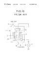
- An apparatus for forming the DLC film disclosed in the above publicationcomprises the followings. As shown in FIG. 16, a cathode 2 is disposed in a reaction chamber 1 having an inlet 1 A for carbon resource gas which generates carbon or is converted to carbon and an outlet 1 B, and a laboratory tool 3 such as a beaker is accommodated in a space 2 A formed in the cathode 2 .
- the reaction chamber 1is decompressed by discharging air from the outlet 1 B after an earthed anode 4 is inserted into an inner space of the laboratory tool 3 .
- the reaction chamber 1accommodates the cathode 2 and the anode 4 , so that the volume of the reaction chamber 1 is remarkably large in comparison with that of the laboratory tool 3 to be coated. Therefore, it causes wastes of time and energy for a vacuum operation of the reaction chamber. Furthermore, since the film forming speed (rate) in the above DLC film forming apparatus is 10 to 1000 ⁇ per minute, which speed is slow, there is a problem in which it is difficult to continuously form the film at a low cost.
- the conventional DLC film forming apparatus described aboveis applied to laboratory tools such as beakers and flasks so as to mainly further increase their qualities, so that the manufacturing cost and time thereof is not much considered.
- containers used for beveragessuch as beer and orange juice must be manufactured in large quantities at low cost. Accordingly, the DLC film forming apparatus cannot be applied to the containers used for beverages.
- Containers for beveragesoften collide with each other during the manufacturing process in a factory or during the selling process in a store, unlike a laboratory tool such as a beaker or a flask.
- a laboratory toolsuch as a beaker or a flask.
- a plastic container of this inventioncomprises a bottle for beverages made of a plastic material with a hard carbon film formed only on an inner surface thereof.
- the hard carbon filmcomprises a diamond like carbon film.
- permeability of the container against low molecular inorganic gas such as oxygen and carbon dioxidecan be remarkably lowered, and furthermore, the sorption in the plastic of various low molecular organic compounds having a smell can be completely suppressed.
- the formation of the hard carbon filmdoes not deteriorate the transparency of the plastic container.
- the hard carbon filmpreferably comprises a diamond like carbon film.
- the diamond like carbon filmis a kind of hard carbon film which is called i-carbon film or hydrogenated amorphous carbon film, and is amorphous carbon film mainly including SP 3 bond.
- the thickness of the diamond like carbon filmis preferably within a range of 0.05-5 ⁇ m.
- the thickness of the diamond like carbon filmlimited to the above range, adhesive property of the film to plastic material, the durability and transparency and the like of the container can be obtained, and in addition, the sorption in the plastic of low molecular organic compound can be effectively suppressed and gas barrier property of the container can be improved.
- the following resinsare used as plastic material for containers.
- the plastic container with a hard carbon film formed on an inner surface thereofWhen the plastic container with a hard carbon film formed on an inner surface thereof is applied to a bottle for beverages, the plastic container can be returnably used in place of a conventional glass container.
- the plastic container coated with a hard carbon film of the inventionhas an excellent gas barrier property and can completely suppress the sorption in the plastic of low molecular organic compound such as odor component, thus making it possible that the container is extensively used as a packaging container in various many fields and as a returnable container capable of refilling therein. Furthermore, since the hard carbon film is formed only on the inner surface of the container in the invention, there is no concern over the damage of the formed hard carbon film during handling of the container.
- the hard carbon film formed on the inner surface of the containercomprises a diamond like carbon film, the above-mentioned effects become more remarkable.
- FIG. 1is a longitudinally sectional view showing an embodiment of a manufacturing apparatus for manufacturing a plastic container coated with carbon film according to this invention
- FIG. 2is a partially enlarged sectional view of the above embodiment
- FIG. 3is a plan view of an insulating plate of the above embodiment
- FIG. 4is a longitudinally sectional view showing an embodiment of a plastic container coated with carbon film according to this invention.
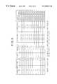
- FIG. 5is a table showing conditions for forming hard carbon film
- FIG. 6is a table showing results evaluating thickness of film and the like of hard carbon film formed under the conditions shown in FIG. 5;
- FIG. 7is a table showing results evaluating oxygen permeability and the like of the hard carbon film formed under the conditions shown in FIG. 5;
- FIG. 8is a graph showing transmitted light spectrum in the ultraviolet and visible region of the plastic container with the hard carbon film formed thereon under the conditions shown in FIG. 5;
- FIG. 9is a graph showing Raman spectrum of the hard carbon film formed under the conditions shown in FIG. 5;
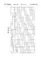
- FIG. 10is a table showing other conditions for forming the hard carbon film
- FIG. 11is a table showing results evaluating thickness and the like of hard carbon film formed under the conditions shown in FIG. 10;
- FIG. 12is a table showing results evaluating oxygen permeability and the like of the hard carbon film under the conditions shown in FIG. 10;
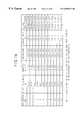
- FIG. 13is a table showing further other conditions for forming the hard carbon film
- FIG. 14is a table showing results evaluating thickness and the like of the hard carbon film formed under the conditions shown in FIG. 13;
- FIG. 15is a table showing results evaluating permeability and the like of the hard carbon film formed under the conditions shown in FIG. 13;
- FIG. 16is a longitudinally sectional view showing a prior art.
- FIG. 1shows a manufacturing apparatus for manufacturing a plastic container coated with carbon film according to the invention.
- the manufacturing apparatushas a ceramic insulating plate 11 fixed on a base 10 , on which insulating plate an external electrode 12 is mounted.
- the external electrode 12itself serves at the same time as a vacuum chamber for forming a DLC film, inside of which external electrode a space is formed for accommodating a container 20 to be coated.
- the space formed in the external electrode 12is slightly larger than the container 20 accommodated therein.
- the container 20is a bottle for beverage, however, the container may be used for other objects.
- the external electrode 12comprises a main body 12 A and a cover 12 B provided detachably on the main body 12 A so as to tightly close the interior of the main body 12 A.
- a high frequency power source 14is connected to the lower portion of the external electrode 12 through a matching device 13 and connecting members 30 , 30 provided on the base 10 .
- a discharging pipe 15is communicated as shown in FIG. 1 with the space formed in the external electrode 12 so as to discharge air in the space by a vacuum pump not shown.
- An internal electrode 16is inserted into the space of the external electrode 12 so as to be disposed at the center portion of the space.
- the discharging pipe 15terminates at the upper surface of the base 10 so as to be opened to a circular space 11 B formed at the center portion of the insulating plate 11 .
- the internal electrode 16is so formed that the electrode 16 can be inserted into the container 20 through the mouth 20 A of the container 20 , and the external shape of the internal electrode 16 is approximately similar figures to the internal shape of the container 20 . It is preferable that the distance between the external electrode 12 and the internal electrode 16 is kept approximately even at every position of the container 20 within the range of 10-150 mm.
- a feed pipe 17 for feeding raw gasis connected with the internal electrode 16 .
- a raw gasis fed through a gas flow rate controller (not shown) from the feed pipe 17 for feeding raw gas into the internal electrode 16 .
- the raw gasthus fed into the internal electrode 16 blows off from a plurality of blowing openings 16 A formed on the internal electrode 16 .
- a plurality of blowing openingsare preferably formed on the side portion of the internal electrode 16 as shown in FIG. 1 in order to evenly diffuse the blown raw gas. However, in case that the raw gas is evenly diffused immediately after being blown off from the internal electrode 16 , one blowing opening may be formed on the top of the internal electrode 16 .
- the internal electrode 16is earthed through the feed pipe 17 for the raw gas.
- the insulating plate 11comprises a short cylindrical body having an outer circumferential surface and an inner circumferential surface, and has a plurality of grooves 11 A (four grooves in this embodiment) as enlargedly shown in FIGS. 2 and 3.
- Each of the grooves 11 Ais disposed at an angular interval of 90° and the bottom surface of each groove 11 A is slanted downwardly from an abutting point P (FIG. 2) to the inner circumferential surface of the insulating plate 11 , at which abutting point an inner circumferential surface of the external electrode 12 is abutted on the insulating plate 11 .
- FIG. 2As shown in FIG.
- an external space 21 A formed between the inner surface of the external electrode 12 and the outer surface of the container 20is communicated with the discharging pipe 15 through the grooves 11 A in a state wherein the container 20 is accommodated in the external electrode 12 with the mouth 20 A of the container 20 abutted against the insulating plate 11 .
- the plastic container 20is inserted from the upper opening of the main body 12 A into the external electrode 12 with the cover 12 B detached from the main body 12 A.
- the internal electrode 16is inserted into the container 20 through the mouth 20 A of the container 20 .
- the mouth 20 Ais abutted against the insulating plate 11 in such manner that the plastic container 20 is placed in an appropriate position in the external electrode 12 , and the cover 12 B then closes the upper opening of the main body 12 A so that the external electrode 12 is tightly sealed.
- the distance between the inner surface of the external electrode 12 and the outer surface of the container 20is maintained approximately even while the distance between the inner surface of the container 20 and the outer surface of the internal electrode 16 is maintained approximately even.
- air in the external electrode 12is discharged through the discharging pipe 15 by a vacuum pump so that the inside of the external electrode 12 becomes vacuum. More specifically, the internal space 21 B as well as the external space 21 A between the outer surface of the container 20 and the inner surface of the external electrode 12 becomes vacuum by means of the grooves 11 A formed in the insulating plate 11 . This is because unless the external space 21 A is vacuum, the temperature in the external space 21 A becomes remarkably high upon generating plasma, thus affecting the plastic material of the container 20 .
- the degree of vacuumis preferably within a range from 10 ⁇ 2 to 10 ⁇ 5 torr. With a lower degree of vacuum of over 10 ⁇ 2 torr, impurities in the container are much increased, on the other hand, with a higher degree of vacuum under 10 ⁇ 5 torr, a long time and a large energy are needed to discharge the air in the container 20 .
- the raw gas as carbon resourceis supplied to the feed pipe 17 through the gas flow rate controller not shown in the drawing, and then thus supplied raw gas is blown off through the blow openings 16 A into the internal space 21 B in the state of vacuum between the outer surface of the internal electrode 16 and the inner surface of the container 20 .
- the flow rate of the raw gasis preferably within a range from 1 to 100 ml/min, by which flow rate of the raw gas the pressure in the internal space 21 B is adjusted within the range from 0.5 to 0.001 torr.
- the pressure in the external space 21 Abecomes lower slightly later than the pressure in the internal space 21 B becomes lower. Therefore, when the discharge of the air is just started, the pressure in the external space 21 A is slightly higher than the pressure in the internal space 21 B. Accordingly, in the case that the supply of the raw gas get started immediately after the discharge of the air in the container is over, the raw gas blown into the internal space 21 B does not get into the external space 21 A.
- Aliphatic hydrocarbons, aromatic hydrocarbons, oxygen containing hydrocarbons, nitrogen containing hydrocarbons, etc., in gaseous or liquid state at a room temperatureare used as the raw gas.
- benzene, toluene, o-xylene, m-xylene, p-xylene and cyclohexane each having six or more than six carbonsare preferable.
- These raw gasesmay be used per se, however, mixture of two or more than two kinds of raw gases may be used. Furthermore, these gases may be used in the state of dilution with inert gas such as argon and helium.
- the formation of the DLC film on the inner surface of the container 20is performed by means of an improved plasma CVD method.
- a low temperature plasmais used in the plasma CVD method, the temperature upon forming the DLC film can be set relatively low. Therefore, the low temperature plasma is suitable in case that an article having a low thermal resistance such as plastic is used as a substrate, and furthermore, the low temperature plasma enables the DLC film to be formed on a wide area at a relatively low cost.
- the low temperature plasmais a plasma in the non-equilibrium state in which electron temperature is high in the plasma and temperatures of ion and neutral molecule are remarkably low in comparison with the temperature of the electron in case that the interior of the reaction chamber is maintained at a low pressure.
- the hard carbon film of the DLC filmis also called as i-carbon film or hydrogenated amorphous carbon film (a-C:H) and is an amorphous carbon film including mainly SP 3 bond.
- the thickness of DLC filmis varied by an output of high frequency, a pressure of the raw gas in the container 20 , a gas flow rate for feeding, period of time during which plasma is generated, self-bias and kind of raw material and the like.
- the thickness of DLC filmis preferably within a range from 0.05 to 5 ⁇ m to obtain the effective suppression of the sorption of the low molecular organic compound and the improved gas barrier property, in addition to an excellent adhesion to plastic, a good durability and a good transparency.
- Quality of the DLC filmis varied by output of the high frequency, the pressure of the raw gas in the container 20 , the gas flow rate, the period of time during which plasma is generated, the self-bias and the kind of raw material in the same manner.
- the output of high frequencyis set within a range from 50 to 1,000 W
- the pressure of raw gas in the container 20is set within a range from 0.2 to 0.01 torr
- the flow rate of supplied gasis set within a range from 10 to 50 ml/min
- the self-biasis set within a range from ⁇ 200 to ⁇ 1,000V
- the carbon numberis set within a range from 1 to 8.
- the inner surface of the container 20may be activated by plasma treatment with inorganic gas such as argon and oxygen before DLC film is formed.
- FIG. 4shows a longitudinal section of plastic container on which the DLC film is formed in the above manner.
- numeral numbers 20 a and 20 bshow a plastic material and a DLC film formed on the inner surface of the plastic material 20 a , respectively.
- the plastic container whose inner surface is coated with the DLC film 20 bcan remarkably decrease permeability of low molecular inorganic gas such as oxygen and carbon dioxide, and simultaneously can completely suppress the sorption of various low molecular organic compounds having odor. Formation of the DLC film does not deteriorate transparency of the plastic container.
- the following resinsare used as plastic materials for containers 20 : polyethylene resin, polypropylene resin, polystyrene resin, cycloolefine copolymer resin, polyethylene terephthalate resin, polyethylene naphthalate resin, ethylene-(vinyl alcohol) copolymer resin, poly-4-methylpentene-1 resin, poly (methyl methacrylate) resin, acrylonitrile resin, polyvinyl chloride resin, polyvinylidene chloride resin, styrene-acrylonitrile resin, acrylonitrile-butadien-styrene resin, polyamide resin, polyamideimide resin, polyacetal resin, polycarbonate resin, polybutylene terephthalate resin, ionomer resin, polysulfone resin, polytetra fluoroethylene resin and the like.
- Maskingwas previously made by Magic Marker (trade mark) on the inner surface of the container, and the DLC film was then formed. Thereafter, the masking was removed by diethyl ether, and thickness of the DLC film was measured by a surface shape measuring device (DECTACK 3) made by Vecco Company.
- DECTACK 3surface shape measuring device
- Adhesion of the DLC film formed on the side surface of the containerwas measured in accordance with cross-cut tape test (JIS K 5400) under the following conditions.
- Adhesion of the DLC film formed on the side surface of the containerwas measured by a continuously weighting type scratch tester (HEIDON 22) made by SHINTO KAGAKU company under the following conditions. Degree of adhesion was indicated by normal load exerted on a scratching needle when the film was started to be peeled off.
- Rate of loading100 g/min
- Alkali solution including sodium hydroxide of 10 wt %was filled into the container which was then immersed in a water bath at a temperature of 75° C. for 24 hours. Then, change of shape of the DLC film and existence of peeling of the DLC film were investigated. “Excellence” in the table shows that shape of DLC film was not changed and peeling thereof did not occur after the immersion for over 24 hours.
- volume of carbon dioxide permeating the DLC filmwas measured by a PERMA TRANC-4 type machine made by MODERN CONTROL Company at a temperature of 25° C.
- volume of oxygen permeating the DLC filmwas measured by an OXTRANTWIN machine made by MODERN CONTROL Company at a temperature of 40° C.
- Low molecular organic compound (aroma component) having odorwas used as a kind of environmental material to test the sorption with reference to a method by MATSUI et al. (J. Agri. Food. Chem., 1992, 40, 1902-1905) in the following manner.
- Model-flavor solutionwas prepared in such a manner that each aroma component (n-octane, n-octanal, n-octanol, ethyl hexanoate, and d-limonene) of 100 ppm was added to sugar ester solution to obtain 0.3% sugar ester solution.
- each aroma componentn-octane, n-octanal, n-octanol, ethyl hexanoate, and d-limonene
- the model flavor solution of 700 mlwas poured into the container, the container was left at a temperature of 20° C. for one month after the mouth of the container was closed with the cover.
- model flavor solutionwas removed from the container to dry the interior of the container after the interior thereof was washed with distilled water of 60° C.
- the diethyl etherwas taken out of the container to dehydrate the diethyl ether by adding sodium sulfuric anhydride thereto.
- a plastic container having a volume of 700 ml and made of polyethylene terephthalate resin (PET resin, Type L125 made by MITSUI PET RESIN COMPANY LIMITED)was accommodated in the external electrode 12 as shown in FIG. 1 to be fixed thereto.
- PET resinpolyethylene terephthalate resin
- the vacuum pumpwas operated to make the inside of the external electrode 12 vacuum (back pressure) of lower than 10 ⁇ 4 torr, and, thereafter, for preliminary treatment, argon was supplied into the plastic container at a flow rate of 30 ml/min to obtain a pressure of 0.04 torr in the container, and Rf power of 300W was supplied to perform plasma treatment on the inner surface of the container. Thereafter, raw gas such as toluene, cyclohexane, benzene or p-xylene was supplied into the interior of the container with using argon as auxiliary gas to uniformly form the DLC film on the inner surface of the container under the conditions shown in FIG. 5 .
- FIG. 6shows the results of the evaluation with respect to thickness of film, film forming velocity, density of film, adhesion 1 of film, adhesion 2 of film and alkali resistance of film.
- the density of each filmexceeded 2.00 g/cm 3 , and the formed film was remarkably dense.
- the adhesion to polyethylene terephthalate resinwas good, and it was verified that the container was sufficient to be of practical use. Furthermore, it was found that alkali resistance was good, and the DLC film was stable enough to completely protect the polyethylene terephthalate resin.
- FIG. 8shows the transmitted light spectrum in ultraviolet and visible region at the barrel portion of the plastic container, the inner surface of which was coated with the DLC film.
- Light transmittance ratewas abruptly decreased in a region from approximately 500 nm of wave length to the ultraviolet region. This suggests that the coating with the use of the DLC film is effective enough to suppress the deterioration of contents by ultraviolet.
- FIG. 9shows Raman spectrum of the thin film formed on the barrel portion of the plastic container under the conditions of Test 1.
- the DLC filmwas formed on the inner surface of the container in the same manner as Test 1 except that a plastic container, having a volume of 700 ml made of styrene-aecrylonitrile copolymer resin (made by Mitsubishi Monsant Kasei Company: PAN resin, type L700) was used.
- the conditions for forming the DLC filmare shown in FIG. 10 .
- testswere performed in connection with the DLC film, namely, thickness, density, adhesion 1 , adhesion 2 , alkali resistance, carbon dioxide barrier property, oxygen gas barrier property and sorption of low molecular organic compound.
- the results of the test in connection with the DLC filmnamely, thickness of film, film forming velocity, density of film, adhesion 1 of film, adhesion 2 of film and alkali resistance of film were shown in FIG. 11 .
- the thickness of the film and the density thereofwere good in the same way as Test 1. It was found that the adhesions 1 and 2 were good in the same way as Test 1 and the adhesion between the DLC film and the styrene-acrylonitrile copolymer was of practical use in the same way as that between DLC film and polyethylene terephthalate resin.
- FIG. 12shows oxygen permeability, carbon dioxide permeability and degree of sorption of each aroma component. More specifically, it was found that styrene-acrylonitrile copolymer resin was inherently excellent in gas barrier property, and further, the permeating amount of each of oxygen and carbon dioxide with respect to styrene-acrylonitrile copolymer resin was remarkably decreased to an extremely lower level by the formation of the DLC film. Amount of the sorption of each aroma component was smaller than the detectable limit, and there was no problem in sensory test in the same way as Test 1.
- the DLC filmwas formed on the inner surface of the container in the same manner as Test 1 except that a plastic container having a volume of 700 ml made of cycloolefine copolymer resin (made by MITSUI PETROCHEMICAL COMPANY LIMITED: COC resin, type APL 6015) was used.
- the conditions for forming the DLC filmare shown in FIG. 13 .
- testswere performed in connection with the DLC film, namely, thickness of film, density of film, adhesion 1 of film, adhesion 2 of film, alkali resistance of film, carbon dioxide barrier property of film, oxygen gas barrier property of film and sorption of film to low molecular organic compound.
- FIG. 15shows results of the oxygen permeability of the DLC film, the carbon dioxide permeability thereof and the sorption of each aroma component.
- Cycloolefine copolymer resinhas comparatively large oxygen permeability carbon dioxide permeability and sorption of aroma components because it is olefine type resin.
- the formation of the DLC film on the containercould considerably suppress the oxygen permeability, the carbon dioxide permeability and the sorption of aroma components.
- the plastic container coated with carbon film of the inventioncan be used as a returnable container such as a bottle for beer, sake as well as beverage.
Landscapes
- Chemical & Material Sciences (AREA)
- Engineering & Computer Science (AREA)
- Mechanical Engineering (AREA)
- General Chemical & Material Sciences (AREA)
- Chemical Kinetics & Catalysis (AREA)
- Materials Engineering (AREA)
- Metallurgy (AREA)
- Organic Chemistry (AREA)
- Ceramic Engineering (AREA)
- Inorganic Chemistry (AREA)
- Details Of Rigid Or Semi-Rigid Containers (AREA)
- Chemical Vapour Deposition (AREA)
- Containers Having Bodies Formed In One Piece (AREA)
- Wrappers (AREA)
- Coating Of Shaped Articles Made Of Macromolecular Substances (AREA)
- Carbon And Carbon Compounds (AREA)
Abstract
Description
Claims (12)
Priority Applications (2)
| Application Number | Priority Date | Filing Date | Title |
|---|---|---|---|
| US10/452,213US6805931B2 (en) | 1994-08-11 | 2003-06-03 | Plastic container coated with carbon film |
| US10/452,208US20030207115A1 (en) | 1994-08-11 | 2003-06-03 | Plastic container coated with carbon film |
Applications Claiming Priority (3)
| Application Number | Priority Date | Filing Date | Title |
|---|---|---|---|
| JP6-189223 | 1994-08-11 | ||
| JP6189223AJPH0853116A (en) | 1994-08-11 | 1994-08-11 | Carbon film coated plastic container |
| PCT/JP1995/001582WO1996005111A1 (en) | 1994-08-11 | 1995-08-09 | Carbon film-coated plastic container |
Related Parent Applications (1)
| Application Number | Title | Priority Date | Filing Date |
|---|---|---|---|
| PCT/JP1995/001582A-371-Of-InternationalWO1996005111A1 (en) | 1994-08-11 | 1995-08-09 | Carbon film-coated plastic container |
Related Child Applications (2)
| Application Number | Title | Priority Date | Filing Date |
|---|---|---|---|
| US10/452,213DivisionUS6805931B2 (en) | 1994-08-11 | 2003-06-03 | Plastic container coated with carbon film |
| US10/452,208DivisionUS20030207115A1 (en) | 1994-08-11 | 2003-06-03 | Plastic container coated with carbon film |
Publications (1)
| Publication Number | Publication Date |
|---|---|
| US6589619B1true US6589619B1 (en) | 2003-07-08 |
Family
ID=16237641
Family Applications (3)
| Application Number | Title | Priority Date | Filing Date |
|---|---|---|---|
| US08/776,702Expired - Fee RelatedUS6589619B1 (en) | 1994-08-11 | 1995-08-09 | Recycling method |
| US10/452,213Expired - Fee RelatedUS6805931B2 (en) | 1994-08-11 | 2003-06-03 | Plastic container coated with carbon film |
| US10/452,208AbandonedUS20030207115A1 (en) | 1994-08-11 | 2003-06-03 | Plastic container coated with carbon film |
Family Applications After (2)
| Application Number | Title | Priority Date | Filing Date |
|---|---|---|---|
| US10/452,213Expired - Fee RelatedUS6805931B2 (en) | 1994-08-11 | 2003-06-03 | Plastic container coated with carbon film |
| US10/452,208AbandonedUS20030207115A1 (en) | 1994-08-11 | 2003-06-03 | Plastic container coated with carbon film |
Country Status (11)
| Country | Link |
|---|---|
| US (3) | US6589619B1 (en) |
| EP (2) | EP1254845A3 (en) |
| JP (2) | JPH0853116A (en) |
| KR (1) | KR100398742B1 (en) |
| AT (1) | ATE228462T1 (en) |
| CA (1) | CA2196888C (en) |
| DE (1) | DE69528982T2 (en) |
| DK (1) | DK0773166T3 (en) |
| MY (1) | MY155224A (en) |
| TW (1) | TW316929B (en) |
| WO (1) | WO1996005111A1 (en) |
Cited By (14)
| Publication number | Priority date | Publication date | Assignee | Title |
|---|---|---|---|---|
| US20030027369A1 (en)* | 2001-07-03 | 2003-02-06 | Semiconductor Energy Laboratory Co., Ltd. | Light-emitting device, method of manufacturing a light-emitting device, and electronic equipment |
| US20030110822A1 (en)* | 2001-04-19 | 2003-06-19 | Kiyonori Shimada | Gas-barrier synthetic resin vessel, device for producing the same, and article-received gas-barrier synthetic resin vessel |
| US20030124229A1 (en)* | 2000-02-24 | 2003-07-03 | Kenichi Hama | Plastic container for dry solid food |
| US20030150858A1 (en)* | 2000-08-01 | 2003-08-14 | Jean-Tristan Outreman | Plasma coating method |
| US20030207115A1 (en)* | 1994-08-11 | 2003-11-06 | Kirin Beer Kabushiki Kaisha | Plastic container coated with carbon film |
| US20050266191A1 (en)* | 1999-12-27 | 2005-12-01 | Kenichi Hama | PET container for foods and drinks containing recycled resin and having DLC coating film formed on surface thereof |
| US20060051539A1 (en)* | 2002-05-28 | 2006-03-09 | Kirin Brewery Company, Limited | Dlc film coated plastic container, and device and method for manufacturing the plastic container |
| US7166336B1 (en)* | 1999-05-19 | 2007-01-23 | Mitsubishi Shoji Plastics Corporation | DLC film, DLC-coated plastic container, and method and apparatus for manufacturing DLC-coated plastic container |
| US7352584B1 (en) | 2005-05-10 | 2008-04-01 | Chien-Min Sung | Diamond-like carbon coated devices |
| US20100200587A1 (en)* | 2007-08-14 | 2010-08-12 | Toyo Seikan Kaisha, Ltd. | Biodegradable resin container with a vacuum-evaporated film and method of forming a vacuum-evaporated film |
| US9404334B2 (en) | 2012-08-31 | 2016-08-02 | Baker Hughes Incorporated | Downhole elastomeric components including barrier coatings |
| US9410245B2 (en) | 2010-12-28 | 2016-08-09 | Kirin Beer Kabushiki Kaisha | Gas-barrier plastic molded product and manufacturing process therefor |
| US20160369396A1 (en)* | 2014-03-03 | 2016-12-22 | Picosun Oy | Protecting an interior of a gas container with an ald coating |
| JP2018016340A (en)* | 2016-07-26 | 2018-02-01 | 三菱ケミカル株式会社 | Polyethylene terephthalate container having gas barrier film |
Families Citing this family (55)
| Publication number | Priority date | Publication date | Assignee | Title |
|---|---|---|---|---|
| JP3256459B2 (en)* | 1996-05-20 | 2002-02-12 | 株式会社大協精工 | Sanitary goods container and method for producing the same |
| JP3637687B2 (en)* | 1996-07-13 | 2005-04-13 | 日新電機株式会社 | Manufacturing method of diaphragm for automobile |
| US6893720B1 (en) | 1997-06-27 | 2005-05-17 | Nissin Electric Co., Ltd. | Object coated with carbon film and method of manufacturing the same |
| FR2776540B1 (en) | 1998-03-27 | 2000-06-02 | Sidel Sa | BARRIER-EFFECT CONTAINER AND METHOD AND APPARATUS FOR ITS MANUFACTURING |
| JP3024751B2 (en) | 1998-04-22 | 2000-03-21 | 日本電気株式会社 | Frame offset setting system, setting method, and setting program recording medium |
| CZ305416B6 (en) | 1999-08-06 | 2015-09-09 | Plastipak Packaging, Inc. | Blow molded multilayer container with carbon coating on inner surface |
| US6475579B1 (en) | 1999-08-06 | 2002-11-05 | Plastipak Packaging, Inc. | Multi-layer plastic container having a carbon-treated internal surface and method for making the same |
| JP2001139075A (en)* | 1999-11-15 | 2001-05-22 | Hokkai Can Co Ltd | Aerosol container |
| JP4492985B2 (en)* | 2000-02-24 | 2010-06-30 | 三菱商事プラスチック株式会社 | Liquid medicine plastic container and liquid medicine storage and recovery method |
| JP2001240034A (en)* | 2000-02-24 | 2001-09-04 | Mitsubishi Shoji Plast Kk | Plastic container for liquid containing volatile organic substance |
| JP3952695B2 (en)* | 2000-05-26 | 2007-08-01 | 学校法人金沢工業大学 | Method and apparatus for surface modification of polymer compound container |
| JP2002002649A (en)* | 2000-06-27 | 2002-01-09 | Hokkai Can Co Ltd | Polyethylene terephthalate resin container |
| JP3993971B2 (en)* | 2000-08-09 | 2007-10-17 | 北海製罐株式会社 | Plastic container having gas barrier coating layer and method for producing the same |
| US6461699B1 (en) | 2000-10-06 | 2002-10-08 | Plastipak Packaging, Inc. | Plastic container having a carbon-treated internal surface for non-carbonated food products |
| JP4595276B2 (en)* | 2000-12-25 | 2010-12-08 | 東洋製罐株式会社 | Microwave plasma processing method and apparatus |
| EP1229068B1 (en)* | 2001-02-06 | 2005-09-14 | Shibuya Kogyo Co., Ltd. | Method and apparatus for modifying the inner surface of containers made of polymeric compound |
| US6822391B2 (en) | 2001-02-21 | 2004-11-23 | Semiconductor Energy Laboratory Co., Ltd. | Light emitting device, electronic equipment, and method of manufacturing thereof |
| DE10129951A1 (en)* | 2001-06-21 | 2003-01-09 | Fleming Claudia | Manufacture of diffusion-resistant plastic hose, especially for air conditioning systems on vehicles, involves filling it with ignitable gas and igniting it with a corona discharge |
| JP2003104386A (en)* | 2001-09-28 | 2003-04-09 | Toppan Printing Co Ltd | Ceramic coated plastic container |
| JP4166455B2 (en) | 2001-10-01 | 2008-10-15 | 株式会社半導体エネルギー研究所 | Polarizing film and light emitting device |
| JP4024510B2 (en) | 2001-10-10 | 2007-12-19 | 株式会社半導体エネルギー研究所 | Recording medium and substrate |
| DE10152055A1 (en)* | 2001-10-25 | 2003-05-08 | Nttf Gmbh | Mechanically and thermodynamically stable amorphous carbon layers for temperature-sensitive surfaces |
| AU2002249596A1 (en)* | 2002-04-15 | 2003-10-27 | Mitsubishi Shoji Plastics Corporation | System and method for forming dlc film on inner surface of plastic container |
| CN100335376C (en)* | 2002-04-26 | 2007-09-05 | 北海制罐株式会社 | Plastic container with inner surface coated and method for producing the same |
| US6995377B2 (en) | 2002-08-02 | 2006-02-07 | Plastipak Packaging, Inc. | Process and apparatus for testing bottles |
| US20060169026A1 (en)* | 2003-02-28 | 2006-08-03 | Tsuyoshi Kage | Method of measuring gas barrier property of plastic molding |
| JP4437647B2 (en)* | 2003-07-17 | 2010-03-24 | 三菱商事プラスチック株式会社 | Method for producing gas container coated plastic container |
| JP3826933B2 (en) | 2003-10-24 | 2006-09-27 | 東洋インキ製造株式会社 | Colorant for thermoplastic resin and use thereof |
| AT414338B1 (en)* | 2004-05-28 | 2010-03-15 | Gruber Karl Dr | ELECTROLYTE CLEANING METHOD WITH BIPOLAR PLASTIC DIAMOND ELECTRODES |
| AT413109B (en)* | 2004-05-28 | 2005-11-15 | Gruber Karl Dipl Ing Dr | DIAMOND ELECTRODE ON PLASTIC BASE |
| FR2872148B1 (en)* | 2004-06-24 | 2006-09-22 | Sidel Sas | BOTTLE PROCESSING MACHINE EQUIPPED WITH AN INTERCHANGEABLE CONNECTION CARTRIDGE |
| JP2006064416A (en)* | 2004-08-24 | 2006-03-09 | Takeshi Kage | Method and apparatus for measuring gas barrier property of plastic molded body |
| JP2006089073A (en)* | 2004-09-22 | 2006-04-06 | Hokkai Can Co Ltd | Inner surface coated plastic container and method of manufacturing |
| JP4171452B2 (en) | 2004-10-18 | 2008-10-22 | 三菱重工食品包装機械株式会社 | Barrier film forming internal electrode and film forming apparatus |
| JP4725093B2 (en)* | 2004-12-10 | 2011-07-13 | 東洋製罐株式会社 | Microwave processing equipment |
| WO2007035741A2 (en)* | 2005-09-20 | 2007-03-29 | Dow Global Technologies Inc. | Process for plasma assisted coating a nanocomposite object |
| US20090324892A1 (en)* | 2006-03-17 | 2009-12-31 | Masataka Hasegawa | Laminate and Method for Depositing Carbon Film |
| US20100211180A1 (en)* | 2006-03-21 | 2010-08-19 | Jet Engineering, Inc. | Tetrahedral Amorphous Carbon Coated Medical Devices |
| JP5324460B2 (en)* | 2006-11-22 | 2013-10-23 | インテグリス・インコーポレーテッド | Diamond-like carbon coating on substrate housing |
| WO2008077468A1 (en)* | 2006-12-21 | 2008-07-03 | Alpla Werke Alwin Lehner Gmbh & Co. Kg | Formulation, preform produced thereof, and method for the production of stretch blow-molded opaque plastic containers |
| US20080202414A1 (en)* | 2007-02-23 | 2008-08-28 | General Electric Company | Methods and devices for coating an interior surface of a plastic container |
| JP5355860B2 (en) | 2007-03-16 | 2013-11-27 | 三菱重工食品包装機械株式会社 | Barrier film forming apparatus, barrier film forming method, and barrier film coating container |
| US8470421B2 (en)* | 2007-06-06 | 2013-06-25 | Toyo Seikan Kaisha, Ltd. | Biodegradable resin bottle and method of producing the same |
| JP2009127059A (en)* | 2007-11-20 | 2009-06-11 | Tokyo Denki Univ | Method for forming diamond-like carbon film |
| WO2009096019A1 (en)* | 2008-01-31 | 2009-08-06 | Nihon Yamamura Glass Co., Ltd. | Cap and container with cap |
| CN102700111B (en)* | 2008-03-27 | 2015-06-24 | 东洋制罐株式会社 | Stretched and foamed plastic container and method of producing the same |
| JP5122386B2 (en)* | 2008-07-09 | 2013-01-16 | 株式会社ダン・タクマ | Case for semiconductor |
| WO2010095011A1 (en) | 2009-02-18 | 2010-08-26 | Council Of Scientific & Industrial Research | Process to deposit diamond like carbon as protective coating on inner surface of a shaped object. |
| US20110001103A1 (en)* | 2009-07-01 | 2011-01-06 | Chi-Kuang Chen | Elevating mechanism for measuring concentrations of medicines |
| JP5610536B2 (en)* | 2011-03-17 | 2014-10-22 | 麒麟麦酒株式会社 | Coated plastic molded body and method for producing the same |
| JP6394050B2 (en)* | 2014-05-07 | 2018-09-26 | 凸版印刷株式会社 | Packaging container with function to prevent odor residue |
| US10894625B1 (en) | 2020-07-29 | 2021-01-19 | Verre Vert, Inc. | Lightweight polymer bottle for wine and spirits |
| JP7686354B2 (en)* | 2022-01-31 | 2025-06-02 | 株式会社吉野工業所 | Plastic bottles |
| CN115384033A (en)* | 2022-09-20 | 2022-11-25 | 湖南千山制药机械股份有限公司 | Plastic container internal plating module, injection blow-plating all-in-one machine and injection blow-plating encapsulation all-in-one machine |
| US12012253B1 (en) | 2023-03-02 | 2024-06-18 | Verre Vert, Inc. | Lightweight polymer wine bottle suitable for use with natural cork or synthetic stoppers |
Citations (22)
| Publication number | Priority date | Publication date | Assignee | Title |
|---|---|---|---|---|
| US4746538A (en)* | 1986-01-14 | 1988-05-24 | Centre National De La Recherche Scientifique (Cnrs) | Process for depositing a thin layer of a material on the wall of a hollow body |
| US4756964A (en)* | 1986-09-29 | 1988-07-12 | The Dow Chemical Company | Barrier films having an amorphous carbon coating and methods of making |
| US4809876A (en)* | 1987-08-27 | 1989-03-07 | Aluminum Company Of America | Container body having improved gas barrier properties |
| JPH01201477A (en)* | 1988-02-05 | 1989-08-14 | Semiconductor Energy Lab Co Ltd | Formation of carbon film |
| JPH0270059A (en) | 1987-12-02 | 1990-03-08 | Idemitsu Petrochem Co Ltd | Appliance and its production |
| JPH02138469A (en)* | 1988-11-16 | 1990-05-28 | Hitachi Ltd | Vacuum material having a diamond surface, surface treatment method for this vacuum material, method for producing a diamond film surface, vacuum container using vacuum material and its parts, vacuum drive mechanism, electron emission source, vacuum heater and evaporation source container |
| JPH02144574A (en) | 1988-11-25 | 1990-06-04 | Toshiba Corp | Electrophotographic system printer device |
| JPH02144574U (en) | 1989-05-08 | 1990-12-07 | ||
| JPH03130363A (en)* | 1989-10-16 | 1991-06-04 | Nikon Corp | Plastic articles coated with diamond-like carbon film |
| JPH04304373A (en)* | 1991-03-29 | 1992-10-27 | Shimadzu Corp | Hard carbon film forming method |
| US5318806A (en)* | 1992-10-02 | 1994-06-07 | Becton, Dickinson And Company | Tube having regions of different surface chemistry and method therefor |
| US5521351A (en)* | 1994-08-30 | 1996-05-28 | Wisconsin Alumni Research Foundation | Method and apparatus for plasma surface treatment of the interior of hollow forms |
| US5529815A (en)* | 1994-11-03 | 1996-06-25 | Lemelson; Jerome H. | Apparatus and method for forming diamond coating |
| US5693376A (en)* | 1995-06-23 | 1997-12-02 | Wisconsin Alumni Research Foundation | Method for plasma source ion implantation and deposition for cylindrical surfaces |
| US5702770A (en)* | 1996-01-30 | 1997-12-30 | Becton, Dickinson And Company | Method for plasma processing |
| US5707691A (en)* | 1996-08-27 | 1998-01-13 | The Coca-Cola Company | Coating hollow containers by in-situ polymerization of monomers in bi-axially orientated form |
| US5798139A (en)* | 1994-08-11 | 1998-08-25 | Kirin Beer Kabushiki Kaisha | Apparatus for and method of manufacturing plastic container coated with carbon film |
| US5976653A (en)* | 1992-07-07 | 1999-11-02 | Continental Pet Technologies, Inc. | Multilayer preform and container with polyethylene naphthalate (PEN), and method of forming same |
| JP2000015770A (en)* | 1998-06-30 | 2000-01-18 | Think Laboratory Co Ltd | Method for reusing printing plate |
| US6045916A (en)* | 1996-02-09 | 2000-04-04 | Kirin Beer Kabushiki Kaisha | Coating film and preparation method thereof |
| JP3130363B2 (en) | 1992-04-21 | 2001-01-31 | 株式会社フジクラ | Manufacturing method of optical fiber coupler |
| US6294226B1 (en)* | 1997-02-19 | 2001-09-25 | Kirin Beer Kabushiki Kaisha | Method and apparatus for producing plastic container having carbon film coating |
Family Cites Families (20)
| Publication number | Priority date | Publication date | Assignee | Title |
|---|---|---|---|---|
| JPS5878732A (en)* | 1981-11-05 | 1983-05-12 | Toyo Seikan Kaisha Ltd | Method for manufacturing coated oriented plastic bottles |
| WO1984001352A1 (en)* | 1982-09-29 | 1984-04-12 | Nat Can Corp | Multiwalled container and method of making same |
| JPS5981126A (en) | 1983-08-24 | 1984-05-10 | Hitachi Ltd | Manufacture of resin mold product |
| JPS60228250A (en)* | 1984-04-24 | 1985-11-13 | テルモ株式会社 | Vessel made of synthetic resin and manufacture thereof |
| US4725464A (en)* | 1986-05-30 | 1988-02-16 | Continental Pet Technologies, Inc. | Refillable polyester beverage bottle and preform for forming same |
| JPH0676666B2 (en)* | 1987-02-10 | 1994-09-28 | 株式会社半導体エネルギ−研究所 | Carbon film production method |
| JPH01100277A (en)* | 1987-10-12 | 1989-04-18 | Idemitsu Petrochem Co Ltd | Curved plate stuck with rigid carbonaceous film, manufacture and manufacturing device thereof |
| JPH04331917A (en)* | 1991-05-07 | 1992-11-19 | Ricoh Co Ltd | Liquid crystal display device |
| JPH0535660A (en) | 1991-07-31 | 1993-02-12 | Toshiba Corp | Signal processor |
| JP2579128Y2 (en)* | 1991-10-17 | 1998-08-20 | 共同印刷株式会社 | Small plastic containers |
| US5255783A (en)* | 1991-12-20 | 1993-10-26 | Fluoroware, Inc. | Evacuated wafer container |
| JP3017602B2 (en)* | 1992-05-27 | 2000-03-13 | 日精エー・エス・ビー機械株式会社 | Refillable plastic container |
| MX9303141A (en)* | 1992-05-28 | 1994-04-29 | Polar Materials Inc | METHODS AND DEVICES FOR DEPOSITING BARRIER COATINGS. |
| US5308649A (en)* | 1992-06-26 | 1994-05-03 | Polar Materials, Inc. | Methods for externally treating a container with application of internal bias gas |
| CA2100275A1 (en)* | 1992-07-22 | 1994-01-23 | Mitchell K. Antoon, Jr. | Blood collection assembly |
| JPH0644558A (en)* | 1992-07-24 | 1994-02-18 | Matsushita Electric Ind Co Ltd | Magnetic recording medium |
| US5346600A (en)* | 1992-08-14 | 1994-09-13 | Hughes Aircraft Company | Plasma-enhanced magnetron-sputtered deposition of materials |
| WO1994011544A1 (en)* | 1992-11-13 | 1994-05-26 | Energy Conversion Devices, Inc. | Microwave apparatus for depositing thin films |
| JPH0853116A (en)* | 1994-08-11 | 1996-02-27 | Kirin Brewery Co Ltd | Carbon film coated plastic container |
| BR0204833B1 (en)* | 2001-04-19 | 2012-05-02 | machine making a gas barrier synthetic resin container, and gas barrier synthetic resin container. |
- 1994
- 1994-08-11JPJP6189223Apatent/JPH0853116A/enactivePending
- 1995
- 1995-07-11KRKR1019950020268Apatent/KR100398742B1/ennot_activeExpired - Lifetime
- 1995-07-15TWTW084107388Apatent/TW316929B/zhnot_activeIP Right Cessation
- 1995-08-09WOPCT/JP1995/001582patent/WO1996005111A1/enactiveIP Right Grant
- 1995-08-09USUS08/776,702patent/US6589619B1/ennot_activeExpired - Fee Related
- 1995-08-09ATAT95927996Tpatent/ATE228462T1/enactive
- 1995-08-09DEDE69528982Tpatent/DE69528982T2/ennot_activeExpired - Lifetime
- 1995-08-09DKDK95927996Tpatent/DK0773166T3/enactive
- 1995-08-09CACA002196888Apatent/CA2196888C/ennot_activeExpired - Fee Related
- 1995-08-09EPEP02012807Apatent/EP1254845A3/ennot_activeWithdrawn
- 1995-08-09EPEP95927996Apatent/EP0773166B1/ennot_activeExpired - Lifetime
- 1995-08-11MYMYPI95002346Apatent/MY155224A/enunknown
- 2000
- 2000-03-13JPJP2000073951Apatent/JP3545305B2/ennot_activeExpired - Lifetime
- 2003
- 2003-06-03USUS10/452,213patent/US6805931B2/ennot_activeExpired - Fee Related
- 2003-06-03USUS10/452,208patent/US20030207115A1/ennot_activeAbandoned
Patent Citations (22)
| Publication number | Priority date | Publication date | Assignee | Title |
|---|---|---|---|---|
| US4746538A (en)* | 1986-01-14 | 1988-05-24 | Centre National De La Recherche Scientifique (Cnrs) | Process for depositing a thin layer of a material on the wall of a hollow body |
| US4756964A (en)* | 1986-09-29 | 1988-07-12 | The Dow Chemical Company | Barrier films having an amorphous carbon coating and methods of making |
| US4809876A (en)* | 1987-08-27 | 1989-03-07 | Aluminum Company Of America | Container body having improved gas barrier properties |
| JPH0270059A (en) | 1987-12-02 | 1990-03-08 | Idemitsu Petrochem Co Ltd | Appliance and its production |
| JPH01201477A (en)* | 1988-02-05 | 1989-08-14 | Semiconductor Energy Lab Co Ltd | Formation of carbon film |
| JPH02138469A (en)* | 1988-11-16 | 1990-05-28 | Hitachi Ltd | Vacuum material having a diamond surface, surface treatment method for this vacuum material, method for producing a diamond film surface, vacuum container using vacuum material and its parts, vacuum drive mechanism, electron emission source, vacuum heater and evaporation source container |
| JPH02144574A (en) | 1988-11-25 | 1990-06-04 | Toshiba Corp | Electrophotographic system printer device |
| JPH02144574U (en) | 1989-05-08 | 1990-12-07 | ||
| JPH03130363A (en)* | 1989-10-16 | 1991-06-04 | Nikon Corp | Plastic articles coated with diamond-like carbon film |
| JPH04304373A (en)* | 1991-03-29 | 1992-10-27 | Shimadzu Corp | Hard carbon film forming method |
| JP3130363B2 (en) | 1992-04-21 | 2001-01-31 | 株式会社フジクラ | Manufacturing method of optical fiber coupler |
| US5976653A (en)* | 1992-07-07 | 1999-11-02 | Continental Pet Technologies, Inc. | Multilayer preform and container with polyethylene naphthalate (PEN), and method of forming same |
| US5318806A (en)* | 1992-10-02 | 1994-06-07 | Becton, Dickinson And Company | Tube having regions of different surface chemistry and method therefor |
| US5798139A (en)* | 1994-08-11 | 1998-08-25 | Kirin Beer Kabushiki Kaisha | Apparatus for and method of manufacturing plastic container coated with carbon film |
| US5521351A (en)* | 1994-08-30 | 1996-05-28 | Wisconsin Alumni Research Foundation | Method and apparatus for plasma surface treatment of the interior of hollow forms |
| US5529815A (en)* | 1994-11-03 | 1996-06-25 | Lemelson; Jerome H. | Apparatus and method for forming diamond coating |
| US5693376A (en)* | 1995-06-23 | 1997-12-02 | Wisconsin Alumni Research Foundation | Method for plasma source ion implantation and deposition for cylindrical surfaces |
| US5702770A (en)* | 1996-01-30 | 1997-12-30 | Becton, Dickinson And Company | Method for plasma processing |
| US6045916A (en)* | 1996-02-09 | 2000-04-04 | Kirin Beer Kabushiki Kaisha | Coating film and preparation method thereof |
| US5707691A (en)* | 1996-08-27 | 1998-01-13 | The Coca-Cola Company | Coating hollow containers by in-situ polymerization of monomers in bi-axially orientated form |
| US6294226B1 (en)* | 1997-02-19 | 2001-09-25 | Kirin Beer Kabushiki Kaisha | Method and apparatus for producing plastic container having carbon film coating |
| JP2000015770A (en)* | 1998-06-30 | 2000-01-18 | Think Laboratory Co Ltd | Method for reusing printing plate |
Cited By (25)
| Publication number | Priority date | Publication date | Assignee | Title |
|---|---|---|---|---|
| US20030207115A1 (en)* | 1994-08-11 | 2003-11-06 | Kirin Beer Kabushiki Kaisha | Plastic container coated with carbon film |
| US7166336B1 (en)* | 1999-05-19 | 2007-01-23 | Mitsubishi Shoji Plastics Corporation | DLC film, DLC-coated plastic container, and method and apparatus for manufacturing DLC-coated plastic container |
| US20050266191A1 (en)* | 1999-12-27 | 2005-12-01 | Kenichi Hama | PET container for foods and drinks containing recycled resin and having DLC coating film formed on surface thereof |
| US20030124229A1 (en)* | 2000-02-24 | 2003-07-03 | Kenichi Hama | Plastic container for dry solid food |
| US20030150858A1 (en)* | 2000-08-01 | 2003-08-14 | Jean-Tristan Outreman | Plasma coating method |
| US20050019577A1 (en)* | 2000-08-01 | 2005-01-27 | Sidel | Method of depositing coating by plasma; device for implementing the method and coating obtained by said method |
| US20030110822A1 (en)* | 2001-04-19 | 2003-06-19 | Kiyonori Shimada | Gas-barrier synthetic resin vessel, device for producing the same, and article-received gas-barrier synthetic resin vessel |
| US6854309B2 (en)* | 2001-04-19 | 2005-02-15 | Nissei Asb Machine Co., Ltd. | Gas-barrier synthetic resin vessel, device for producing the same, and article-received gas-barrier synthetic resin vessel |
| US7129102B2 (en) | 2001-07-03 | 2006-10-31 | Semiconductor Energy Laboratory Co., Ltd. | Light-emitting device, method of manufacturing a light-emitting device, and electronic equipment |
| US7067976B2 (en) | 2001-07-03 | 2006-06-27 | Semiconductor Energy Laboratory Co., Ltd. | Light-emitting device, method of manufacturing a light-emitting device, and electronic equipment |
| US20060220551A1 (en)* | 2001-07-03 | 2006-10-05 | Semiconductor Energy Laboratory Co., Ltd. | Light-emitting device, method of manufacturing a light-emitting device, and electrocic equipment |
| US20030027369A1 (en)* | 2001-07-03 | 2003-02-06 | Semiconductor Energy Laboratory Co., Ltd. | Light-emitting device, method of manufacturing a light-emitting device, and electronic equipment |
| US20050088088A1 (en)* | 2001-07-03 | 2005-04-28 | Semiconductor Energy Laboratory Co., Ltd. | Light-emitting device, method of manufacturing a light-emitting device, and electronic equipment |
| US7372200B2 (en) | 2001-07-03 | 2008-05-13 | Semiconductor Energy Laboratory Co., Ltd. | Light-emitting device, method of manufacturing a light-emitting device, and electronic equipment |
| US20100275847A1 (en)* | 2002-05-28 | 2010-11-04 | Kirin Beer Kabushiki Kaisha | Dlc film coated plastic container, and device and method for manufacturing the plastic container |
| US7754302B2 (en)* | 2002-05-28 | 2010-07-13 | Kirin Brewery Company, Limted | DLC film coated plastic container, and device and method for manufacturing the plastic container |
| US20060051539A1 (en)* | 2002-05-28 | 2006-03-09 | Kirin Brewery Company, Limited | Dlc film coated plastic container, and device and method for manufacturing the plastic container |
| US7352584B1 (en) | 2005-05-10 | 2008-04-01 | Chien-Min Sung | Diamond-like carbon coated devices |
| US20100200587A1 (en)* | 2007-08-14 | 2010-08-12 | Toyo Seikan Kaisha, Ltd. | Biodegradable resin container with a vacuum-evaporated film and method of forming a vacuum-evaporated film |
| US8950614B2 (en)* | 2007-08-14 | 2015-02-10 | Toyo Seikan Kaisha, Ltd. | Biodegradable resin container with a vacuum-evaporated film and method of forming a vacuum-evaporated film |
| US9410245B2 (en) | 2010-12-28 | 2016-08-09 | Kirin Beer Kabushiki Kaisha | Gas-barrier plastic molded product and manufacturing process therefor |
| US9404334B2 (en) | 2012-08-31 | 2016-08-02 | Baker Hughes Incorporated | Downhole elastomeric components including barrier coatings |
| US20160369396A1 (en)* | 2014-03-03 | 2016-12-22 | Picosun Oy | Protecting an interior of a gas container with an ald coating |
| US11326254B2 (en)* | 2014-03-03 | 2022-05-10 | Picosun Oy | Protecting an interior of a gas container with an ALD coating |
| JP2018016340A (en)* | 2016-07-26 | 2018-02-01 | 三菱ケミカル株式会社 | Polyethylene terephthalate container having gas barrier film |
Also Published As
| Publication number | Publication date |
|---|---|
| TW316929B (en) | 1997-10-01 |
| EP0773166A4 (en) | 1999-08-25 |
| WO1996005111A1 (en) | 1996-02-22 |
| MY155224A (en) | 2015-09-30 |
| JP3545305B2 (en) | 2004-07-21 |
| DE69528982D1 (en) | 2003-01-09 |
| KR960007662A (en) | 1996-03-22 |
| DE69528982T2 (en) | 2003-08-28 |
| CA2196888C (en) | 2005-06-07 |
| US20030207115A1 (en) | 2003-11-06 |
| JPH0853116A (en) | 1996-02-27 |
| JP2000309324A (en) | 2000-11-07 |
| DK0773166T3 (en) | 2003-03-17 |
| CA2196888A1 (en) | 1996-02-22 |
| EP0773166B1 (en) | 2002-11-27 |
| KR100398742B1 (en) | 2003-12-11 |
| EP0773166A1 (en) | 1997-05-14 |
| EP1254845A2 (en) | 2002-11-06 |
| US20030203143A1 (en) | 2003-10-30 |
| US6805931B2 (en) | 2004-10-19 |
| EP1254845A3 (en) | 2006-02-15 |
| ATE228462T1 (en) | 2002-12-15 |
Similar Documents
| Publication | Publication Date | Title |
|---|---|---|
| US6589619B1 (en) | Recycling method | |
| US5798139A (en) | Apparatus for and method of manufacturing plastic container coated with carbon film | |
| US5919328A (en) | Blood collection tube assembly | |
| RU2189401C2 (en) | Container coated by material with barrier effect, method and device for manufacture thereof | |
| US7166336B1 (en) | DLC film, DLC-coated plastic container, and method and apparatus for manufacturing DLC-coated plastic container | |
| US20030215652A1 (en) | Transmission barrier layer for polymers and containers | |
| JP2004504938A (en) | Plasma-deposited barrier coating with a boundary layer, method for obtaining such a coating, and a container thus obtained | |
| GB2151262A (en) | Methods for improving the gas barrier properties of polymeric containers | |
| JPH11348171A (en) | Transparent barrier film and laminate using the same | |
| JP4050649B2 (en) | How to use bottles for carbon film coating beverages | |
| JP4050648B2 (en) | Carbon film coated beverage bottle | |
| JP2001158415A (en) | Plastic bottle for atmospheric low temperature plasma treatment and its manufacturing method | |
| JP2003327248A (en) | Method for producing carbon film coated beverage bottle | |
| JP2004168325A (en) | Barrier plastic container | |
| JP3864126B2 (en) | Inner coated polyester resin container | |
| JP2018158753A (en) | Plastic bottle | |
| JP2002361778A (en) | Gas barrier film, its laminate and their manufacturing methods | |
| KR20190024259A (en) | Plastic container having excellent gas barrier property and manufacturing method thereof | |
| JP2001146529A (en) | Method of forming thin film on plastic container |
Legal Events
| Date | Code | Title | Description |
|---|---|---|---|
| AS | Assignment | Owner name:KIRIN BEER KABUSHIKI KAISHA, JAPAN Free format text:ASSIGNMENT OF ASSIGNORS INTEREST;ASSIGNOR:NAGASHIMA, KAZUFUMI;REEL/FRAME:008608/0185 Effective date:19970131 | |
| FEPP | Fee payment procedure | Free format text:PAYER NUMBER DE-ASSIGNED (ORIGINAL EVENT CODE: RMPN); ENTITY STATUS OF PATENT OWNER: LARGE ENTITY | |
| FPAY | Fee payment | Year of fee payment:4 | |
| AS | Assignment | Owner name:KIRIN HOLDINGS KABUSHIKI KAISHA, JAPAN Free format text:CHANGE OF NAME;ASSIGNOR:KIRIN BEER KABUSHIKI KAISHA;REEL/FRAME:021147/0855 Effective date:20071120 Owner name:KIRIN BEER KABUSHIKI KAISHA, JAPAN Free format text:ASSIGNMENT OF ASSIGNORS INTEREST;ASSIGNOR:KIRIN HOLDINGS KABUSHIKI KAISHA;REEL/FRAME:021158/0106 Effective date:20080208 Owner name:KIRIN HOLDINGS KABUSHIKI KAISHA,JAPAN Free format text:CHANGE OF NAME;ASSIGNOR:KIRIN BEER KABUSHIKI KAISHA;REEL/FRAME:021147/0855 Effective date:20071120 Owner name:KIRIN BEER KABUSHIKI KAISHA,JAPAN Free format text:ASSIGNMENT OF ASSIGNORS INTEREST;ASSIGNOR:KIRIN HOLDINGS KABUSHIKI KAISHA;REEL/FRAME:021158/0106 Effective date:20080208 | |
| FPAY | Fee payment | Year of fee payment:8 | |
| REMI | Maintenance fee reminder mailed | ||
| LAPS | Lapse for failure to pay maintenance fees | ||
| STCH | Information on status: patent discontinuation | Free format text:PATENT EXPIRED DUE TO NONPAYMENT OF MAINTENANCE FEES UNDER 37 CFR 1.362 | |
| FP | Lapsed due to failure to pay maintenance fee | Effective date:20150708 |