US6589244B1 - Bone fastener and instrument for insertion thereof - Google Patents
Bone fastener and instrument for insertion thereofDownload PDFInfo
- Publication number
- US6589244B1 US6589244B1US09/840,198US84019801AUS6589244B1US 6589244 B1US6589244 B1US 6589244B1US 84019801 AUS84019801 AUS 84019801AUS 6589244 B1US6589244 B1US 6589244B1
- Authority
- US
- United States
- Prior art keywords
- fastening member
- bone
- internal
- fastener
- base
- Prior art date
- Legal status (The legal status is an assumption and is not a legal conclusion. Google has not performed a legal analysis and makes no representation as to the accuracy of the status listed.)
- Expired - Fee Related, expires
Links
- 210000000988bone and boneAnatomy0.000titleclaimsabstractdescription182
- 238000003780insertionMethods0.000titleabstractdescription3
- 230000037431insertionEffects0.000titleabstractdescription3
- 238000000034methodMethods0.000claimsabstractdescription37
- 229910001220stainless steelInorganic materials0.000claimsdescription6
- RTAQQCXQSZGOHL-UHFFFAOYSA-NTitaniumChemical compound[Ti]RTAQQCXQSZGOHL-UHFFFAOYSA-N0.000claimsdescription5
- 239000010935stainless steelSubstances0.000claimsdescription5
- 239000010936titaniumSubstances0.000claimsdescription5
- 239000004677NylonSubstances0.000claimsdescription4
- 239000004809TeflonSubstances0.000claimsdescription4
- 229920006362Teflon®Polymers0.000claimsdescription4
- 229910001069Ti alloyInorganic materials0.000claimsdescription4
- 239000000560biocompatible materialSubstances0.000claimsdescription4
- 229920001778nylonPolymers0.000claimsdescription4
- 229920002379silicone rubberPolymers0.000claimsdescription4
- 229910052719titaniumInorganic materials0.000claimsdescription4
- 239000002253acidSubstances0.000claims3
- 230000008878couplingEffects0.000claims2
- 238000010168coupling processMethods0.000claims2
- 238000005859coupling reactionMethods0.000claims2
- 238000007428craniotomyMethods0.000abstractdescription31
- 210000003625skullAnatomy0.000abstractdescription24
- 210000004556brainAnatomy0.000abstractdescription7
- 230000000295complement effectEffects0.000description10
- 238000000926separation methodMethods0.000description7
- 239000007787solidSubstances0.000description7
- 230000007547defectEffects0.000description6
- 239000000463materialSubstances0.000description6
- 210000001951dura materAnatomy0.000description4
- 230000000717retained effectEffects0.000description4
- 238000001356surgical procedureMethods0.000description4
- 238000007373indentationMethods0.000description3
- 208000015181infectious diseaseDiseases0.000description3
- 210000003205muscleAnatomy0.000description3
- 239000004033plasticSubstances0.000description3
- 229920003023plasticPolymers0.000description3
- 208000002847Surgical WoundDiseases0.000description2
- 230000004888barrier functionEffects0.000description2
- 239000012620biological materialSubstances0.000description2
- 230000036770blood supplyEffects0.000description2
- 230000006835compressionEffects0.000description2
- 238000007906compressionMethods0.000description2
- 238000005553drillingMethods0.000description2
- 210000003128headAnatomy0.000description2
- 229920001903high density polyethylenePolymers0.000description2
- 239000004700high-density polyethyleneSubstances0.000description2
- 238000007917intracranial administrationMethods0.000description2
- 230000000926neurological effectEffects0.000description2
- 210000004761scalpAnatomy0.000description2
- 210000001519tissueAnatomy0.000description2
- 210000000689upper legAnatomy0.000description2
- 208000009078Depressed Skull FractureDiseases0.000description1
- 229910001200FerrotitaniumInorganic materials0.000description1
- 239000004698PolyethyleneSubstances0.000description1
- 229920000954PolyglycolidePolymers0.000description1
- 241000826860TrapeziumSpecies0.000description1
- 230000000845anti-microbial effectEffects0.000description1
- 239000004599antimicrobialSubstances0.000description1
- 239000008280bloodSubstances0.000description1
- 210000004369bloodAnatomy0.000description1
- 210000001124body fluidAnatomy0.000description1
- 239000010839body fluidSubstances0.000description1
- 239000000084colloidal systemSubstances0.000description1
- 238000003851corona treatmentMethods0.000description1
- 239000002537cosmeticSubstances0.000description1
- 239000000645desinfectantSubstances0.000description1
- 230000003467diminishing effectEffects0.000description1
- 239000012634fragmentSubstances0.000description1
- 210000002454frontal boneAnatomy0.000description1
- 238000007306functionalization reactionMethods0.000description1
- 208000014674injuryDiseases0.000description1
- 238000002955isolationMethods0.000description1
- 210000004373mandibleAnatomy0.000description1
- 210000002050maxillaAnatomy0.000description1
- 239000007769metal materialSubstances0.000description1
- 230000003278mimic effectEffects0.000description1
- 230000000399orthopedic effectEffects0.000description1
- 210000003455parietal boneAnatomy0.000description1
- 230000001936parietal effectEffects0.000description1
- 230000001575pathological effectEffects0.000description1
- -1polyethylenePolymers0.000description1
- 229920000573polyethylenePolymers0.000description1
- 239000004633polyglycolic acidSubstances0.000description1
- 230000002035prolonged effectEffects0.000description1
- 230000005855radiationEffects0.000description1
- 230000000284resting effectEffects0.000description1
- 239000004945silicone rubberSubstances0.000description1
- 230000001954sterilising effectEffects0.000description1
- 238000004659sterilization and disinfectionMethods0.000description1
- 239000000126substanceSubstances0.000description1
- 210000003582temporal boneAnatomy0.000description1
- 230000008733traumaEffects0.000description1
- 239000002023woodSubstances0.000description1
Images


Classifications
- A—HUMAN NECESSITIES
- A61—MEDICAL OR VETERINARY SCIENCE; HYGIENE
- A61B—DIAGNOSIS; SURGERY; IDENTIFICATION
- A61B17/00—Surgical instruments, devices or methods
- A61B17/56—Surgical instruments or methods for treatment of bones or joints; Devices specially adapted therefor
- A61B17/58—Surgical instruments or methods for treatment of bones or joints; Devices specially adapted therefor for osteosynthesis, e.g. bone plates, screws or setting implements
- A61B17/68—Internal fixation devices, including fasteners and spinal fixators, even if a part thereof projects from the skin
- A61B17/688—Internal fixation devices, including fasteners and spinal fixators, even if a part thereof projects from the skin for reattaching pieces of the skull
- A—HUMAN NECESSITIES
- A61—MEDICAL OR VETERINARY SCIENCE; HYGIENE
- A61B—DIAGNOSIS; SURGERY; IDENTIFICATION
- A61B17/00—Surgical instruments, devices or methods
- A61B17/56—Surgical instruments or methods for treatment of bones or joints; Devices specially adapted therefor
- A61B17/58—Surgical instruments or methods for treatment of bones or joints; Devices specially adapted therefor for osteosynthesis, e.g. bone plates, screws or setting implements
- A61B17/88—Osteosynthesis instruments; Methods or means for implanting or extracting internal or external fixation devices
- A61B17/8875—Screwdrivers, spanners or wrenches
- A61B17/8886—Screwdrivers, spanners or wrenches holding the screw head
- A61B17/8888—Screwdrivers, spanners or wrenches holding the screw head at its central region
- A—HUMAN NECESSITIES
- A61—MEDICAL OR VETERINARY SCIENCE; HYGIENE
- A61F—FILTERS IMPLANTABLE INTO BLOOD VESSELS; PROSTHESES; DEVICES PROVIDING PATENCY TO, OR PREVENTING COLLAPSING OF, TUBULAR STRUCTURES OF THE BODY, e.g. STENTS; ORTHOPAEDIC, NURSING OR CONTRACEPTIVE DEVICES; FOMENTATION; TREATMENT OR PROTECTION OF EYES OR EARS; BANDAGES, DRESSINGS OR ABSORBENT PADS; FIRST-AID KITS
- A61F2/00—Filters implantable into blood vessels; Prostheses, i.e. artificial substitutes or replacements for parts of the body; Appliances for connecting them with the body; Devices providing patency to, or preventing collapsing of, tubular structures of the body, e.g. stents
- A61F2/02—Prostheses implantable into the body
- A61F2/28—Bones
- A61F2/2875—Skull or cranium
- Y—GENERAL TAGGING OF NEW TECHNOLOGICAL DEVELOPMENTS; GENERAL TAGGING OF CROSS-SECTIONAL TECHNOLOGIES SPANNING OVER SEVERAL SECTIONS OF THE IPC; TECHNICAL SUBJECTS COVERED BY FORMER USPC CROSS-REFERENCE ART COLLECTIONS [XRACs] AND DIGESTS
- Y10—TECHNICAL SUBJECTS COVERED BY FORMER USPC
- Y10S—TECHNICAL SUBJECTS COVERED BY FORMER USPC CROSS-REFERENCE ART COLLECTIONS [XRACs] AND DIGESTS
- Y10S606/00—Surgery
- Y10S606/907—Composed of particular material or coated
- Y10S606/908—Bioabsorbable material
Definitions
- This inventionrelates to a fastener for securing a bone plate to surrounding bone, for example when replacing a portion of the cranial vault removed during a craniotomy for a neurosurgical procedure.
- the inventionalso relates to an instrument for securing two threaded members to each other.
- the instrumentmay be used during neurosurgical procedures, or as a mechanical tool in many other contexts.
- a craniotomyis a surgical procedure in which a portion of the cranial vault is removed or folded back in a flap to permit surgical access to the cranial contents (such as the brain).
- several burr holesare drilled through the skull. The number and position of these holes varies depending on the shape of bone to be removed. For example, three burr holes are drilled at corner points if a triangular bone flap is desired.
- the burr holesare then connected by osteotomy cuts, for example using a Gigli flexible saw which is passed internally between the burr holes. The saw is then oscillated back and forth to cut the skull along a line of separation (defined by the connecting osteotomies) connecting adjoining burr holes.
- the bone coveris subsequently lifted off the underlying dura mater to expose the brain. The bone cover may either be completely removed from the surgical site, or folded back in a flap along an uncut edge of the flap.
- the bone coverAfter completion of the operation, the bone cover must again be fixed in its original position to protect the underlying brain.
- Conventional craniotomy closurerequires that holes be drilled in the bone plate and surrounding cranium along the osteotomy lines, and stainless steel wire or silk sutures are then passed through the holes to retain the plate in place.
- drilling the holesis time consuming and potentially dangerous, because of the risk of introducing infection.
- the suturesare also unstable and prone to breakage. Suture instability or breakage can lead to dangerous movements of the cranial plate against the brain, with pathologic sequelae similar to a depressed skull fracture.
- the sutures closing the osteotomy linesare not aesthetically pleasing, because they can leave irregularities in the overlying surface of the face or scalp. This irregularity is particularly unsightly if the surface of the bone plate is not held substantially co-planar with the surrounding bone.
- U.S. Pat. No. 5,201,737discloses a flexible plate having a plurality of vanes with holes for receiving bone screws. The plate is placed over a cranial burr hole and adjoining osteotomy lines to provide external fixation of the bone cover to the surrounding cranium.
- fixation devicesare also known for fusing fractured bones.
- An example of such a deviceis U.S. Pat. No. 2,511,051, in which an externally threaded stud screws into an internally threaded shank. Movement of the stud into the shank is guided by an hexagonal wrench that is inserted through the shank into a countersunk receptacle on the tip of the threaded stud.
- U.S. Pat. No. 3,875,936shows an attachment for replacing a trochanteric head to the femur by providing a barbed shear washer between the femur and trochanteric head.
- U.S. Pat. No. 5,098,433uses a winged compression bolt for fusing fractured bones.
- U.S. Pat. No. 5,196,016 and U.S. Pat. No. 5,433,719discloses fixation pins or screws for retaining bone fragments against one another.
- Yet another objectis to provide such a fastener that can be quickly and efficiently installed, and which is capable of easy removal in the event that subsequent intracranial access is required for another neurosurgical procedure.
- Yet another object of the inventionis to provide such a fastener that avoids the aesthetic drawbacks of prior fasteners, such as large indentations in skin overlying the craniotomy.
- the bone cover fastener of the present inventionwhich has internal and external fastening members. At least one of the fastening members has a conforming surface that conforms to a curved surface, such as the inside surface of the cranial vault. In other embodiments, both the internal and external fastening members have conforming surfaces, such that a surface of the internal fastener conforms to the internal surface of the cranium, while the external fastener also has a surface that conforms to the external surface of the cranium.
- the conforming surfacemay be a curved surface of the internal fastening member that seats against the inner face of the cranium.
- the internal and external fastening membersare curved plates that respectively conform to the internal and external curvature of the skull.
- the conforming surfacemay be provided by flexible struts that deform into a curved configuration as the fastener is tightened.
- a tabis provided on one of the fastening members to prevent relative rotation between the fastening member and the cranium.
- the tabis a relatively flat member that extends away from the internal fastening member a sufficient distance to be retained between the bone plate and the remaining cranium.
- the tabis sufficiently thin that it fits within the gap between the bone plate and surrounding cranium.
- One of the connectorsmay be an elongated, externally threaded stud that projects from the first fastening member, while the second connector may be an elongated internally threaded collar that projects from the second fastening member.
- the studis rotationally threaded into the collar, with the collar extending between the fastening members.
- the collarfits through the burr hole of a craniotomy incision, and each fastening member is wider than the collar and the burr hole to provide clamping surfaces above and below the burr hole that engage the internal and external surfaces of the bone cover and surrounding cranium.
- Screwing the threaded stud into the internally threaded collarbrings the opposing fastening members closer together, and tightens them against the internal and external surfaces of the bone cover and surrounding cranium.
- the fastening membersoverlap margins of the burr hole and adjoining osteotomy lines to securely fix the bone cover to the surrounding bone.
- one of the fastening membersis a base which includes a disc having a flat inner face and a flat outer face. A plurality of raised barbs extend from the inner face of the base to provide frictional engagement between the disc and bone.
- the other fastening memberis a cap with an outer face that may be flat or convex, and a recess is provided in the outer face for engaging a drive member that rotates the cap.
- An externally threaded studprojects from an inner face of the base and an internally threaded collar projects from an inner face of the cap.
- the studis approximately as long as the collar.
- the studmay be screwed partially or entirely into the collar, depending on the thickness of the bone cover.
- the fastenerhas the versatility to be used in different locations of the skull, where bone thickness varies.
- the fasteneris used in a method for fixing a bone plate, such as a cranial cover, in a bone defect, such as a craniotomy opening.
- the bone platehas opposing internal and external surfaces that are to be held in position substantially co-planar with internal and external surfaces of surrounding bone.
- the methodprovides the steps of placing the base and cap of the fastening member on opposing internal and external surfaces of the bone plate, with the collar projecting into the hole, and a portion of the base and a portion of the cap overlapping the border of the junction between the bone plate and surrounding bone.
- the base and capare then rotated into threaded engagement with one another, until the cap and base tightly engage opposing surfaces of the bone plate and surrounding bone to clamp the bone plate in place.
- the fasteneris placed through a craniotomy burr hole, with the cap and base covering and closing the burr hole.
- a fastening instrumentto secure first and second members to each other.
- the instrumentincludes a sleeve, a shaft or rod that slides within the sleeve, an attachment mechanism on the sleeve for engaging the first member to the instrument, and an engagement structure on the shaft that engages the second member and pulls it into engagement with the first member.
- the sleeveincludes a handle extending out from the sleeve
- the rodincludes a handle that allows the rod to be rotated and reciprocated relative to the sleeve.
- There is a threaded tip on the rodthat engages an internally threaded collar of the first member to screw the first and second member to be moved into engagement with each other.
- the instrumentincludes a sleeve that has a handle (such as a rod or disc) extending from the sleeve.
- a handlesuch as a rod or disc
- a rodslides within the sleeve, and has a threaded tip at a distal end of the rod, and a handle (such as a disc or curved hand grip) near a proximal end of the rod.
- the handleextends perpendicularly to the rod, and allows an operator to both rotate the rod and move the rod axially within the sleeve.
- a distal tip of the sleeve that surrounds the threaded rodhas a plurality of locking members or prongs that extend from the tip of the sleeve and fit into complementary receptacles on one of the fasteners to lock the fastener to the tip of the sleeve, for example by frictional engagement of the prongs to one of the fasteners.
- the instrumentis designed to engage two threaded fasteners to each other.
- the fastenerincludes a cap and a base, and a receptacle in the cap that engages the prongs on the sleeve to lock the cap to the sleeve.
- the capalso includes an opening through which the rod can slide.
- the base of the fastenerincludes a post having both internal and external threads, and the threaded tip of the rod has threads that are complementary to the internal threads of the post.
- the caphas a collar with internal threads that are complementary to the external threads on the post.
- the fastenersare attached to each other by first engaging the fastener cap to the sleeve of the base by introducing the prongs into the receptacles on the cap.
- the rodis then extended through the cap, and the base secured to the rod by threading the threaded tip of the rod into the internally threaded post of the base.
- the sleeveis then axially advanced over the rod until the external threads of the base post abut the internal threads of the cap collar.
- the rod and sleeveare then rotated relative to each other (for example by rotating the shaft) to screw the externally threaded tip of the post on the base into the internally threaded collar of the cap.
- the threaded rod tipis then unscrewed from the internally threaded post of the base.
- the connected fastenersmay then be disengaged from the instrument, for example by pulling the instrument away from the fasteners to disengage the locking member from the fasteners.
- axial movement of the rod towards the fastenersbrings the threaded rod tip into abutment against the internal threads of the post, and pushes the fasteners off the locking members to disengage the fasteners from the instrument.
- the instrument of the present inventioncan be used with many different types of fasteners, in many situations where two fasteners must be secured to each other in a difficult to reach location.
- the instrumentis particularly useful when the fasteners are to be secured to opposite faces of a barrier that inhibits access to both faces of the barrier.
- One particular fastener with which the instrument can be usedis the bone cover fastener of the present invention.
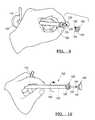
- FIG. 1is a schematic view of a portion of the human skull in which a craniotomy has been performed, and fasteners of the present invention have been placed to secure the cranial cover to surrounding cranium.
- FIG. 2is an enlarged, perspective view of one of the fasteners of the present invention, wherein the cap and base are disengaged.
- FIG. 3is a top view of the cap of the fastener of FIG. 2 .
- FIG. 4is a top view of the base of the fastener of FIG. 2 .
- FIG. 5is a cross-sectional view taken along section line 5 — 5 of FIG. 1 .
- FIG. 6is a cross-sectional view of the fastener shown in FIG. 2 .
- FIG. 7is a cross-sectional view of a fastening instrument suitable for engaging another embodiment of the fasteners to one another.
- FIG. 8is an end elevational view of the fastening instrument of FIG. 7 .
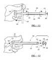
- FIG. 9is a view of a fastener instrument, showing the fastener cap secured to the instrument.
- FIG. 10is a view similar to FIG. 9, but showing both the fastener cap and base secured to the instrument.
- FIG. 11is a view showing how the instrument is manipulated to rotate the fastener base relative to the fastener cap to secure the base and cap to each other.
- FIG. 12is a view showing the instrument disengaged from the assembled fastener.
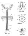
- FIG. 13is a side elevational view showing another embodiment of the fastening instrument, in which the sleeve handle is a disc and the rod handle is a curved handgrip.
- FIG. 13Ais an enlarged view of the tip of the instrument shown in FIG. 13 .
- FIG. 14is a top plan view of another embodiment of the base, showing distribution of the barbs around the inner face of the base.
- FIG. 15is a side elevational view of the base shown in FIG. 14, illustrating the profile of the barbs.
- FIG. 16is a perspective view of the base of another embodiment of the fastener, in which an inner face of the base is convex and an outer face (not shown) of the base is concave.
- FIG. 17is a cross-sectional view of the assembled fastener extending through a craniotomy burr hole and retaining a bone plate in place within a cranial defect.
- FIG. 18is a perspective view of yet another embodiment of the base having flexible struts.
- FIG. 19is a view of the base shown in FIG. 18, but wherein the struts have flexed to conform to an interior curve of an internal face of a bone plate.
- FIG. 20is a top view of the base shown in FIG. 18 .
- FIG. 21is a view of another embodiment of the base which includes multiple struts.
- FIG. 22is a top view of the base shown in FIG. 21 .
- FIG. 23is a cross-sectional view of the fastener shown in FIGS. 21 and 22, illustrating the fastening instrument that is used to assemble the fastener in the bone plate.
- the present inventionincludes fasteners for securing two table-like or curved plate structures to each other.
- the inventionalso includes a positioning instrument that is particularly useful for positioning the fasteners in a surgical wound, and a fastening instrument for securing the fasteners to each other.
- a positioning instrumentthat is particularly useful for positioning the fasteners in a surgical wound
- a fastening instrumentfor securing the fasteners to each other.
- This detailed descriptionwill describe several embodiments of the fasteners, as well as an instrument that can engage the fasteners to each other.
- the instrumentcan be used to secure many different types of fasteners to each other, but is shown in connection with the neurosurgical fasteners for purposes of illustration.
- a clamp 10is shown in the drawings for closing a craniotomy (FIG. 1 ), which is a particular type of table-like structure.
- a craniotomyis performed by incising pericranium and muscle with cutting diathermy in the line of an intended bone flap. An incision is not made interiorly where a pedicle of pericranium or temporalis muscle is often left uncut to allow some blood supply to the bone and overlying tissue to remain intact. Alternatively, the pericranium and muscle may be detached completely from the intended bone flap.
- the craniotomyis performed by making a series of burr holes 12 through the cranium about six or seven centimeters apart with a conventional trephine.
- the underlying dura materis separated from the bone covering the osteotomy site (“the bone cover”) using a periosteal elevator.
- Osteotomies 14 between the burr holes 12are then made using a Gigli flexible saw that is passed between adjacent burr holes and moved back and forth to make the osteotomies from the internal to the external surfaces of the cranium.
- the base of the flapas illustrated in FIG. 1, is not made with a saw.
- a bone forceps(such as a de Vilbis forceps) is used to cut between burr holes until the bridge breaks at base 16 when the flap is elevated.
- a bone plate 18is separated from the surrounding cranium along a line of separation formed by osteotomies 14 .
- Each burr hole 12has a plate portion 12 a and a complementary cranial portion 12 b which together form the completed hole 12 .
- Trephinescome in graduated sizes, for example between 0.5 and 2 inches (13-51 mm) diameter, for drilling burr holes of sizes varying across this usual range.
- the bone plate 18may be completely removed if osteotomies connect all of the burr holes 12 . However, it is often preferred to leave an intact edge of the craniotomy (such as 16 ) to preserve the blood supply to the bone (as shown in FIG. 1 ). In either case, the bone plate or flap is referred to as the cranial cover.
- the bone defectmust be repaired by placing the cranial cover 18 back in the defect with opposing internal surface 20 and external surface 22 (FIG. 5) substantially co-planar or aligned with the internal surface 24 and external surface 26 of surrounding cranium 28 (FIG. 5 ).
- a transverse face 30 of bone cover 18must also be fixed in apposition with a transverse face 32 of cranium 28 , along a border of junction defined by the osteotomy 14 between bone cover 18 and surrounding cranial bone 28 .
- the fastener 10is a one-piece member that includes a base 38 (FIGS. 2, 4 - 6 ) formed by a solid disc 40 having a flat inner face 42 and a flat outer face 44 .
- Inner face 42circumscribes an elongated, cylindrical collar 46 projecting outwardly from the center of inner face 42 .
- An internally threaded bore 48extends longitudinally through collar 46 , but does not extend through disc 40 .
- bore 48 in this embodimentcommunicates only with a round opening 50 at the top of collar 46 , and does not extend through disc 40 , which has a flat, solid, lower face 44 .
- bore 48may extend through the base.
- a plurality of raised, conical or pyramidal barbs 52are integral with and extend upwardly from inner face 42 of disc 40 . As best shown in FIG. 4, four barbs 52 are located on face 42 , equally spaced around disc 40 , and inwardly spaced from the perimeter of the disc. Barbs 52 taper to sharp tips 54 for engaging bone against which the barbs are placed, and into which the barbs may be embedded by pushing the barbs against the bone.
- the cancellous nature of the skull bonemakes it particularly suitable for embedment of the barbs therein.
- Cap 60fastens to base 38 to form a fastener that secures bone cover 18 in place, and occludes the burr holes.
- Cap 60is a solid disc 61 (FIGS. 5-6) with a convex outer face 62 that is smooth except for a recess 64 for engaging a complementary drive member (not shown) that rotates cap 60 .
- the illustrated recess 64is hexagonal, and designed to receive the tip of a surgical instrument resembling an Allen wrench. However, an elongated kerf could alternatively be scored in the surface 62 for receiving the tip of an instrument resembling a screw driver.
- Cap 60has a flat, annular inner face 66 from which an externally threaded stud 68 projects for inter-engagement with internally threaded bore 48 of collar 46 .
- Stud 68projects from the center of face 66 , and the external threads are helical and machined to complement and screw into the internal helical threads of collar 46 .
- the collarresembles a nut into which the cap threads like a bolt.
- Stud 68preferably has a length (extending perpendicularly away from face 66 along a longitudinal axis of fastener 10 ) that is approximately as long as threaded bore 48 of collar 46 .
- cap 60 and base 38are each wider than the outer diameter of cylindrical collar 46 .
- the outer diameter of cylindrical collar 46is less than the diameter of burr holes 12 , but the diameters of discs 40 and 61 are greater than the diameter of burr holes 12 .
- Cap 60 and base 38each have a longitudinal axis of symmetry, such that the fastener when assembled is symmetric.
- the fastener 10is used in a method of replacing a bone plate, such as cranial cover 18 , following a craniotomy.
- the craniotomyis performed by providing a plurality of craniotomy holes, such as burr holes 12 , through the skull.
- the burr holesare subsequently connected by osteotomies 14 to create a separation border for the cranial bone cover (which may be a plate that is removed or a flap that is folded back along one edge).
- the craniotomy openingtherefore includes a portion 12 a of burr hole 12 formed in cranial cover 18 , and a complementary portion 12 b of the hole formed in surrounding cranial bone 28 .
- Bone cover 18has internal face 20 and external face 22 that are respectively placed in substantially co-planar relationship with internal face 24 and external face 26 of the surrounding cranial bone 28 when a craniotomy is closed. Opposing transverse faces 30 , 32 of the bone cover and surrounding bone appose along the separation border when the bone cover is in place. Faces 30 , 32 are substantially parallel to each other when in apposition.
- the bone cover 18is folded back along a base 16 , or completely removed as a plate, to expose the underlying dura mater and brain.
- base 38is placed below each burr hole 12 with the inner face 42 of base 38 against the internal surface 24 of cranium 28 , such that one or more of barbs 52 engage the internal face 24 .
- Base 38overlaps the margins of hole 12 and the separation border between the cranial cover and surrounding bone (as shown in FIG. 1 ).
- Collar 46projects upwardly into or through the portion 12 b of the hole, but preferably does not extend out of the external surface.
- Cranial cover 18is then replaced into the craniotomy opening, for example, by folding the bone flap along base 16 back down into the craniotomy opening.
- cap 60diminishes the distance between base 38 and cap 60 , to tighten inner faces 42 , 66 of the base and cap against the internal and external surfaces of the cranium and cranial cover.
- the cap and baseare thereby brought together in frictional engagement against opposing faces of the cranial cover 18 and surrounding bone 28 , thereby clamping the cranial cover and surrounding bone to each other.
- Barbs 52 of base 38anchor the base to both the cranial cover and surrounding bone, preventing rotation of the base while the cap is screwed into the collar.
- the baseis attached to the bone as barbs 52 become progressively advanced into the bone by tightening of the fastener.
- the fasteneris used to clamp the cranial cover to the surrounding bone at one or more of the burr holes, and preferably all of the burr holes as shown in FIG. 1.
- a base 38is therefore positioned below each burr hole 12 with collar 46 projecting up into the hole prior to replacement of cranial cover 18 .
- a cap 60is then screwed into each internally threaded collar until the cap and base clamp the bone cover 18 and surrounding cranium securely to each other.
- the cap and baseare in a fixed relationship determined by the degree of advancement of the externally threaded stud 68 into the internally threaded collar 46 , so that movement of the bone plate is substantially prevented.
- the bone plate and surrounding boneare held firmly in place with respect to each other, which avoids inadvertent depression of the cranial cover (with attendant catastrophic neurological consequences).
- the smooth, convex top outer face 62 of cap 60diminishes the aesthetic problem of visible indentations on the skull or face overlying the craniotomy burr holes.
- the closed base 44tightly engages the internal surfaces of the cranial cover and surrounding cranium, providing ideal occlusion of the hole, to help avoid infection or trauma.
- the fasteneralso clamps the cranial cover in place quickly, thereby diminishing the period of time the brain must be exposed, and also reduces medical expenses associated with prolonged time in the operating room.
- the fasteneris also easily removed, for example, by inserting an instrument into recess 64 of cap 60 and rotating the cap off of the fastener, to allow the bone flap to be subsequently removed if a follow-up neurosurgical procedure is required.
- the fastener 10is made of any biocompatible material, including stainless steel, titanium alloy, polyglycolic acid, silicone rubber, Teflon or nylon. Titanium is a particularly preferred material. The biocompatibility of these and other materials can be enhanced by functionalization of the surface of the fasteners. Plasma gas discharge and corona treatment with reactive groups introduced on polymeric surfaces have been described as ways to modify biomaterial surfaces. See Lee et al., Biomaterials 12:443, 1991 and Lee et al., J. Colloid Interface Sci. 151:563, 1992.
- the fastener 10may be made in many different sizes.
- the diameter of the stud 68can be 7 mm (the same diameter as cylindrical bore 48 ); the external diameter of collar 46 may be 8 mm; the diameter of disc 61 can be 20 mm; the diameter of disc 40 may be 20 mm.
- stud 68is 6 mm long, which is the same length as collar 46 and its internal bore 48 .
- the fastener of the present inventionis adjustable for use in repairing craniotomies through bone of varying thickness.
- the pterionin the temporoparietal region
- the pterionis quite thin and may require a fastener with a 3 mm stud and collar, with advancement of the cap and base toward each other until the stud 68 has been completely advanced into collar 46 and face 66 of disc 61 abuts against collar 46 .
- the 3 mm stud and collarwould also allow the fastener to clamp bones up to 6 mm thick (if the stud is only initially advanced into the collar).
- the parietal or frontal bonemay be 10-20 mm thick.
- a fastener with a 6 mm long stud 68can clamp bones together varying in thickness from 6 mm to 12 mm.
- a longer stud and collar(for example the stud and collar each 12 mm long) could clamp together bones from about 12 mm thick (when the fastener is fully tightened) to 24 mm thick (when the cap and base are initially engaged but before more rotation of the cap into the base occurs).
- the internally helically threaded collarmay depend from the cap while the externally helically threaded stud may project from the base.
- the cap and basemay assume many shapes other than circular, and may for example be square or triangular.
- Bone plates other than in the skullmay be secured to surrounding bone, for example a relatively flat top bone such as the trapezium, mandible, maxilla, or bones of the orbit.
- the convex face of cap 60may also be flat, particularly in areas of the skull (such as the temporal bone) with relatively flat external surfaces.
- the fastenermay also be used to fix adjacent members together, even where the members are curved.
- the embodiment of the fastener shown in FIGS. 16-23is preferred for curved surfaces, and will be subsequently described.
- FIGS. 7-12An instrument 100 for securing fastener members to each other is shown in FIGS. 7-12 to include an elongated tubular sleeve 102 (see especially FIG. 7) having a proximal end 104 (nearer the surgeon or other user) and a distal end 106 (farther away from the surgeon or other user).
- Two tubular handle members 108 , 110extend diametrically away from each other, perpendicular to the axis of sleeve 102 .
- Distal end 106has two small posts 112 , 114 (FIGS. 7 and 8) projecting 1-3 mm (for example 2-3 mm) away from the flat surface 116 of distal end 106 .
- Posts 112 , 114are spaced approximately 180° from each other, and serve as prongs that fasten the fastener to the instrument.
- An elongated rod 120slides within sleeve 102 .
- a tubular guide member 107may be placed in the sleeve 102 to fill empty space and inhibit relative transverse movement between the sleeve 102 and rod 120 that freely slides axially in the sleeve.
- Rod 120includes a proximal end 122 and a distal end 124 .
- a disc 126is fixed to the proximal end 122 of rod 120 by hex nut 127 , and extends perpendicularly to the longitudinal axis of rod 120 .
- Disc 126provides a handle on the instrument that can be grasped by a user to reciprocate or rotate rod 120 within sleeve 102 .
- the distal end 124 of rod 120has an externally threaded, cylindrical, reduced diameter externally threaded tip 128 .
- sleeve 102is approximately 14 cm long, with the span of arms 108 , 110 being approximately 9 cm.
- Rod 120is longer than sleeve 102 , with a total length of approximately 16 mm from tip 128 to disc 126 .
- the disc 126is a solid, cylindrical disc having a diameter of approximately 31 ⁇ 2 cm. Dimensions of the instrument may vary.
- Instrument 100is used to engage a first and second fastener to each other.
- the first fasteneris a cap 130 , which is in the shape of a disc.
- Two openings 132 , 134 through the diskare complementary to the size and location of posts 112 , 114 on sleeve 102 .
- openings 132 , 134provide receptacles into which posts 112 , 114 can be inserted and snugly received to secure or lock cap 130 to instrument 100 , for example by frictional engagement between the posts 112 , 114 and the receptacles in the cap 130 .
- a central opening 136is provided through the center of the cap, along the axis of rotation of cap 130 .
- Central opening 136has a diameter only slightly greater than the diameter of rod 120 , such that the rod can slide through and be guided by the walls of central opening 136 .
- An internally threaded collar 138projects downwardly from cap 130 around central opening 136 , and the central opening 136 communicates with and can extend through the collar 138 .
- the second fastener memberis a base 140 which has the shape of a plate or disc with a central stud 142 projecting upwardly therefrom. Stud 142 is provided with external helical threads 144 that are complementary with the helical internal threads of collar 138 , such that collar 138 can be rotated to thread cap 130 onto base 140 .
- Three sharp projections 150 , 152 , 154extend upwardly from the disc of base 140 to help lock the base against a bearing surface. These projections 150 - 154 are located at the periphery of base 140 , and are equally spaced about 60° from one another (such that all of the projections are on one-half of the base, preferably all within 120° of each other).
- the projectionsare substantially triangular, and each has a sharp apex that is suitable for embedment in a bearing surface (such as the internal surface of the skull).
- FIG. 9shows the first step, in which rod 120 is inserted through opening 136 of cap 130 until locking posts 112 , 114 are inserted into openings 132 , 134 and cap 130 is secured in place on end 106 of sleeve 102 .
- the frictional engagement between locking posts 112 , 114 and the receptacles formed by openings 132 , 134holds cap 130 on end 106 .
- base 140is then attached to rod 120 by inserting threaded tip 128 (FIG. 9) into internally threaded stud 142 of base 140 (while the base is secured in place against an inner face of the bone plate).
- Rod 120is then rotated in the direction of arrow 146 (FIGS. 8 and 10) to screw threaded tip 128 into internally threaded stud 142 of the base.
- Rod 120is rotated by turning disc 126 until base 140 is tightly secured on the tip.
- the step of threading base 140 onto tip 128is preferably performed with rod 120 fully extended (as shown in FIG. 10) by exerting axial pressure against disc 126 .
- Rod 120is then axially retracted relative to sleeve 102 (or sleeve 102 is advanced relative to rod 120 ) (FIG. 11) to introduce external helical threads 144 on the stud 142 into the internal helical threads in 138 of cap 130 .
- sleeve 102is rotated by turning handle 110 in the rotational direction shown by arrow 146 (FIG. 11 ).
- Base 140will remain stationary, because barbed projections 150 - 154 on the base engage bone, and inhibit rotation of the base.
- rotation of sleeve 102 in the direction shown by arrow 146screws internally threaded collar 138 on to externally threaded stud 142 .
- disc handle 126is then rotated in the direction of arrow 147 (the opposite direction of arrow 146 ) to unscrew threaded tip 128 of the shaft 120 from the internal threads of stud 142 .
- tip 128is fully unscrewed from stud 142 and collar 138
- the tipis axially retracted from opening 136 to fully disengage the instrument 100 from the fastener.
- the instrumentmay then be withdrawn from the surgical wound, leaving the fastener firmly in place engaging the opposing faces of the bone plate and surrounding bone.
- the fastening instrument 100can also be used in non-surgical applications, for example securing a fastener to opposing faces of a work piece such as a wall or adjacent pieces of wood. Variations of the method of using the instrument can also be used, in both surgical and non-surgical applications.
- the base 140can be rotated to screw it on to threaded tip 128 instead of rotating threaded tip 128 to screw it into the base. Only relative rotation between the base and sleeve is needed.
- the base collarcan be screwed into the cap collar by providing relative rotation between the cap and base, without necessarily rotating the cap by turning the sleeve 102 .
- the rodcan instead be rotated (in a direction 147 ) to screw the base into the cap by relative rotation between the base and cap.
- Base disc 140has a lesser diameter than cap 130 .
- base disc 140has a diameter of about 11 mm, while cap 130 has a diameter of about 13 mm.
- Stud 142has a height of about 9 mm, while the height of collar 138 is about 4 mm.
- the smaller diameter of base disc 140helps the base fit better against the interior face of the cranial vault, which has a steeper curvature than the curvature of the outer cranial cover.
- the barbs 150 , 152 and 154are all within a 120° sector of base disc 140 . This allows the barbs to be placed on the intact portion of the skull bone, without being embedded into the removable portion of the cranial cover. Hence the cranial cover can be removed when desired by disengaging the cap and base, without disengaging the barbs from the bone of the plate that is to be removed.
- FIGS. 13-13AAnother embodiment of the fastener instrument is shown in FIGS. 13-13A, and is designated instrument 200 .
- This instrumentis similar to instrument 100 shown in FIGS. 7-12, hence like parts have been given like reference numerals plus 100 to denote the similar parts, beginning with instrument 200 .
- This embodimentdiffers, however, in that the rod handle 226 is not a disc, but is instead a handle grip with an arcuate frusto-hemispherical outer face.
- the handle 226may be hemispherical or spherical in shape. The advantage of this shape is that it presents an arcuate side surface that can be easily grasped by the hand, with the fingers directed somewhat inwardly (toward the longitudinal axis of the instrument 200 ).
- Handle 226provides a secure handgrip that is also easily rotated during use of the instrument.
- the sleeve handle 210also differs from the perpendicular rods 108 , 110 that served as the sleeve handle in instrument 100 .
- the sleeve handleis instead a disc that circumscribes the sleeve 202 and extends perpendicularly outwardly therefrom.
- the circumferential face 211 of disc 210is serrated or otherwise roughened to increase frictional engagement between face 211 and the hand of a surgeon or other user of the instrument. Improved frictional engagement between the handle and hand is particularly helpful, for example, in surgical procedures during which blood or other body fluids may moisten the handle and make it slippery.
- FIG. 13Aalso shows an alternative embodiment of the posts or prongs in which a circular coil spring or O-ring 215 (shown in place on post 212 ) is seated in an annular indentation (shown as 217 ) on each post.
- the coil springis somewhat resilient, such that the spring is slightly compressed as posts 212 , 214 are introduced into the receptacles of the cap.
- FIGS. 14 and 15Another embodiment of the fastener base is shown in FIGS. 14 and 15.
- the base 340is shown with six barbs 350 , 352 , 354 , 356 , 358 and 360 distributed equally around the periphery of and extending from the inner face 341 of base 340 .
- the barbshave a sharp profile, for example the apex of the barb forms and angle ⁇ that is about 30 degrees or less (FIG. 15 ).
- Each barbextends 2-3 mm in height above the surface of inner face 341 . This height has been found to allow the barbs to enter bone (such as a bone plate) to a depth that provides particularly superior engagement between the fastener base and bone plate.
- Distribution of the barbs around the base(instead of placing the barbs in only a sector of the base, for example a 60° or 120° sector) allows the barbs to engage the bone plate even if the base rotates slightly from its original position of placement.
- FIGS. 16-23Other embodiments of the fastener are contemplated as part of the present invention, and shown in FIGS. 16-23.
- a specific embodiment of the fastener 410is shown in FIGS. 16 and 17. That embodiment is similar to the fastener embodiment of FIGS. 5 and 6, except that the cap and base are curved to conform to the shape of the external and internal surface of the cranial vault.
- the range of curvatures of the human skullmay range, for example, from a radius of curvature of 65-105 mm, and the radius of curvature of the cap and base can extend across this same range.
- Fastener 410includes a base 438 and a cap 460 made of polyethylene, and each having a surface with a radius of curvature of 84 mm that fits against the skull.
- the base(which is illustrated in isolation in FIG. 16) has a member 438 which is capable of conforming to the shape of a curved surface against which the member seats.
- member 438has a curved upper surface 440 which has a shape defined by a portion of a sphere.
- the curvature of surface 440is substantially the same as a curvature of the internal surface of the bone plate 18 and surrounding bone 28 that form the internal face of the cranial vault.
- Bottom surface 444 of member 438is also curved (and preferably parallel to curved surface 440 ) so that both the top and bottom surface of the base member 440 mimic the curve of the surrounding cranium. This curvature of the base helps member 438 fit against the internal face of the cranial vault, and avoids damage to surrounding dura mater that can occur when a flat plate fastener base does not conform well to the curvature of the skull.
- top member 461 of cap 460is also curved to conform to the external curvature of the skull, such that cap 460 fits unobtrusively against the external surface of the skull.
- the curved capis less obtrusive than a flate plate, and creates less of a post-surgical cosmetic defect in the overlying scalp.
- the curved platecreates less of a pucker in the overlying tissue.
- base 438includes an upwardly extending tab 453 that extends into the osteotomy incision 14 between burr holes to oppose rotation of base 438 as cap 460 is screwed into it.
- Tab 453is a projection that extends a sufficient distance from base 438 to be retained within the osteotomy incision.
- the tabextends about at least one half the height of collar 446 , or to a height the same height as the collar, or even slightly higher than the collar (as shown in FIG. 17 ).
- the range of tab heightsfor example, may be 0.5 to 11.5 mm.
- Tab 453is preferably a thin plate-like member that is substantially flat (with a thickness no greater than the osteotomy incision), for example, about 1-2 mm thick, or 1 mm thick, and extends radially from collar 446 substantially the entire radial width of base 438 , and has a top that is not sufficiently sharp to penetrate bone.
- the illustrated tab 453has a curved, blunt top 455 .
- FIG. 17Assembly of fastener 410 is illustrated in FIG. 17, which is similar to FIG. 5, and wherein like parts have been given like reference numerals plus 400 , and the fastener 410 is positioned in a burr hole within an osteotomy separation.
- Base 438can be positioned against the internal surface of bones 18 , 28 such that the curved member 438 conforms to the shape of the skull, and tab 453 projects up into the osteotomy separation between bone plate 18 and surrounding bone 28 .
- Base 438can be placed in this position, for example, using the instrument shown in FIGS. 7-10 or FIGS. 13-13A.
- cap 460is then placed above the base, and externally threaded stud 468 is threaded into internally threaded collar 446 by rotating cap 460 .
- Rotation of base 438does not occur as cap 460 is rotated, because tab 453 is retained within the osteotomy incision and abuts against either the bone plate 18 or surrounding bone 28 .
- Stud 468is rotated into collar 446 until cap 460 and base 438 are appropriately tightened against the bone.
- the tab 453can extend from collar 446 instead of surface 440 .
- the baseincludes both surface 440 and collar 446 .
- FIGS. 18-20show a strut embodiment of the base.
- the base 538is made of four flexible strut members 541 , 543 , 545 and 547 that cooperatively form an “X” shaped base.
- Each strutis a thin, rectangular extension that is made of plastic (such as high density polyethylene) or other flexible material, and which can be flexed within about 2-15°, preferably at least 2°, of its resting position (as shown by ⁇ in FIG. 19) without breaking, and in the disclosed example flexes about 5°.
- Internally threaded collar 546(having threaded bore 550 shown in FIG.
- FIGS. 21 and 22Yet another embodiment of the strut base 638 is shown in FIGS. 21 and 22, wherein there are multiple thin flexible struts 641 extending from a central solid portion 639 .
- Collar 646projects upwardly from base 638 .
- Collar 646is externally threaded to accept an internally threaded cap, and is also internally threaded to accept the externally threaded tip of the insertion instrument.
- the thin struts 641are approximately 1 mm thick, and may, for example, be 5-10 mm long.
- FIG. 23shows the base of FIGS. 21 and 22 wherein the flexible struts 641 of the base are bowed to conform to the curvature of the internal skull as the curved cap 630 is tightened by screwing internally threaded cap 630 on to externally threaded collar 646 .
- the fastening instrument 102is also shown attached to the fastener, with threaded tip 128 screwed into the internal threads of collar 646 to hold base 638 against the internal surface of the cranium while curved cap 630 is rotated to screw internally threaded cap 630 on to externally threaded collar 646 .
- the flexible struts of the baseprovide more flexibility than a solid member.
- the strutsare preferably made of a high density polyethylene.
- each strutdoes not occupy more than about a 20-30° sector of the base.
- the disclosed strutsare rectangular in shape, but they can alternatively taper, flare, or assume other shapes that sufficiently reduce the solid areas of the base to increase the flexibility of the base such that it conforms to the curvature of the skull when the fastener is tightened to such an extent that the bone in the skull is not fractured or damaged.
- the modulus of flexibility of the base (or each individual strut)is 300,000 to 700,000 psi.
- the fastener instrument of the present inventionis preferably made of a metallic material that is suitable for sterile use in surgical procedures. Titanium or stainless steel are examples of-such materials, particularly for the embodiments that do not flex.
- the fastener or instrumentmay also be made of a durable plastic material. Plastic is a particularly preferred material for embodiments of the invention that use flexible struts (such as the embodiments of FIGS. 18 - 23 ).
- the inventionalso includes a fastener, positioning instrument, and fastening instrument that has been sterilized, for example in an autoclave, or by irradiation (e.g. irradiation with ultraviolet radiation), or by chemical sterilization (e.g. with disinfectants or anti-microbials).
- the term “conforms to a curved member”does not require identical curvature of the conforming member and the surface to which it conforms. Substantial conformity of the members is all that is required, and that includes surfaces between flat planes and curves that precisely conforms to the curved member against which the conforming number slats.
Landscapes
- Health & Medical Sciences (AREA)
- Orthopedic Medicine & Surgery (AREA)
- Surgery (AREA)
- Life Sciences & Earth Sciences (AREA)
- Biomedical Technology (AREA)
- Nuclear Medicine, Radiotherapy & Molecular Imaging (AREA)
- Engineering & Computer Science (AREA)
- Heart & Thoracic Surgery (AREA)
- Medical Informatics (AREA)
- Molecular Biology (AREA)
- Animal Behavior & Ethology (AREA)
- General Health & Medical Sciences (AREA)
- Public Health (AREA)
- Veterinary Medicine (AREA)
- Neurology (AREA)
- Neurosurgery (AREA)
- Surgical Instruments (AREA)
Abstract
Description
Claims (36)
Priority Applications (1)
| Application Number | Priority Date | Filing Date | Title |
|---|---|---|---|
| US09/840,198US6589244B1 (en) | 1996-02-14 | 2001-04-23 | Bone fastener and instrument for insertion thereof |
Applications Claiming Priority (5)
| Application Number | Priority Date | Filing Date | Title |
|---|---|---|---|
| US1164796P | 1996-02-14 | 1996-02-14 | |
| US1404896P | 1996-03-25 | 1996-03-25 | |
| US08/635,410US5707373A (en) | 1996-04-26 | 1996-04-26 | Bone fastener and instrument for insertion thereof |
| US08/866,201US6258091B1 (en) | 1996-02-14 | 1997-05-30 | Bone fastener and instrument for insertion thereof |
| US09/840,198US6589244B1 (en) | 1996-02-14 | 2001-04-23 | Bone fastener and instrument for insertion thereof |
Related Parent Applications (1)
| Application Number | Title | Priority Date | Filing Date |
|---|---|---|---|
| US08/866,201ContinuationUS6258091B1 (en) | 1996-02-14 | 1997-05-30 | Bone fastener and instrument for insertion thereof |
Publications (1)
| Publication Number | Publication Date |
|---|---|
| US6589244B1true US6589244B1 (en) | 2003-07-08 |
Family
ID=27359466
Family Applications (3)
| Application Number | Title | Priority Date | Filing Date |
|---|---|---|---|
| US08/866,201Expired - LifetimeUS6258091B1 (en) | 1996-02-14 | 1997-05-30 | Bone fastener and instrument for insertion thereof |
| US09/817,766AbandonedUS20020004661A1 (en) | 1996-02-14 | 2001-03-26 | Bone fastener and instrument for insertion thereof |
| US09/840,198Expired - Fee RelatedUS6589244B1 (en) | 1996-02-14 | 2001-04-23 | Bone fastener and instrument for insertion thereof |
Family Applications Before (2)
| Application Number | Title | Priority Date | Filing Date |
|---|---|---|---|
| US08/866,201Expired - LifetimeUS6258091B1 (en) | 1996-02-14 | 1997-05-30 | Bone fastener and instrument for insertion thereof |
| US09/817,766AbandonedUS20020004661A1 (en) | 1996-02-14 | 2001-03-26 | Bone fastener and instrument for insertion thereof |
Country Status (5)
| Country | Link |
|---|---|
| US (3) | US6258091B1 (en) |
| EP (1) | EP0929266A4 (en) |
| JP (1) | JP2000505323A (en) |
| DE (1) | DE29724567U1 (en) |
| WO (1) | WO1997029708A1 (en) |
Cited By (74)
| Publication number | Priority date | Publication date | Assignee | Title |
|---|---|---|---|---|
| US20040030340A1 (en)* | 2001-09-25 | 2004-02-12 | Perumala Corporation | Medical appliance for bridging and stabilizing spaced apart bone segments having a bone screw locking system |
| US20040127908A1 (en)* | 2001-09-25 | 2004-07-01 | Roman Shawn David | Cranial clamp with torque-limiting feature |
| US20040206946A1 (en)* | 2003-01-22 | 2004-10-21 | Lappen Alan Rick | Gate post threaded insert |
| US20040210223A1 (en)* | 2003-04-21 | 2004-10-21 | Madhavan Pisharodi | Fastener for securing two separate workpieces |
| US20050043742A1 (en)* | 2003-08-21 | 2005-02-24 | Aurelian Bruneau | Systems and methods for positioning implants relative to bone anchors in surgical approaches to the spine |
| US20050049599A1 (en)* | 2001-06-15 | 2005-03-03 | Aesculap Ag & Co. Kg | Implant for fixing bone plates |
| US20050125032A1 (en)* | 2003-10-10 | 2005-06-09 | Whisenant Brian K. | Patent foramen ovale (PFO) closure devices, delivery apparatus and related methods and systems |
| US20050159746A1 (en)* | 2004-01-21 | 2005-07-21 | Dieter Grob | Cervical facet resurfacing implant |
| US20050192627A1 (en)* | 2003-10-10 | 2005-09-01 | Whisenant Brian K. | Patent foramen ovale closure devices, delivery apparatus and related methods and systems |
| US20060015106A1 (en)* | 1999-10-30 | 2006-01-19 | Karl-Dieter Lerch | Surgical connecting element for fixing adjacently arranged bone plates |
| US20060087014A1 (en)* | 2004-10-25 | 2006-04-27 | Rubenstein Brandon A | Bolster plate assembly for processor module assembly |
| US20070106283A1 (en)* | 2005-11-07 | 2007-05-10 | Garcia Saddy R | Driver assembly and fastener apparatus |
| US20070173844A1 (en)* | 2006-01-17 | 2007-07-26 | Ralph James D | Craniotomy closures and plugs |
| US20070250059A1 (en)* | 2004-08-04 | 2007-10-25 | Dieter Weisshaupt | Implant for securing neighbouring bone plates |
| US20090076617A1 (en)* | 2006-01-17 | 2009-03-19 | Ralph James D | Craniotomy Closures |
| WO2007008348A3 (en)* | 2005-07-06 | 2009-04-16 | Howard A Stone | Surgical system for joints |
| US20090112208A1 (en)* | 2007-10-25 | 2009-04-30 | Borgia Anthony V | External bone screw system and method of use for fractures, fusions or osteotomies |
| US20090204152A1 (en)* | 2004-02-06 | 2009-08-13 | Spinal Elements, Inc. | Vertebral facet joint prosthesis and method of fixation |
| US20090245557A1 (en)* | 2008-03-31 | 2009-10-01 | Cochlear Limited | Piercing conducted bone conduction device |
| US20100036413A1 (en)* | 2008-08-06 | 2010-02-11 | Peter Nakaji | Kerf cranial closure methods and device |
| US7736380B2 (en) | 2004-12-21 | 2010-06-15 | Rhausler, Inc. | Cervical plate system |
| US20100331919A1 (en)* | 2009-06-30 | 2010-12-30 | Boston Scientific Neuromodulation Corporation | Moldable charger having hinged sections for charging an implantable pulse generator |
| US20100331920A1 (en)* | 2009-06-30 | 2010-12-30 | Boston Scientific Neuromodulation Corporation | Moldable charger with shape-sensing means for an implantable pulse generator |
| US20100331918A1 (en)* | 2009-06-30 | 2010-12-30 | Boston Scientific Neuromodulation Corporation | Moldable charger with curable material for charging an implantable pulse generator |
| US20100331917A1 (en)* | 2009-06-30 | 2010-12-30 | Boston Scientific Neuromodulation Corporation | Moldable charger with support members for charging an implantable pulse generator |
| US20110028973A1 (en)* | 2009-07-31 | 2011-02-03 | Rohit Khanna | Cranial fixation device |
| US20110034959A1 (en)* | 2007-12-19 | 2011-02-10 | Sevrain Lionel C | Spring-assisted cranial clamp |
| US7887587B2 (en) | 2004-06-04 | 2011-02-15 | Synthes Usa, Llc | Soft tissue spacer |
| US20110046682A1 (en)* | 2009-07-06 | 2011-02-24 | Synthes Gmbh Or Synthes Usa, Llc | Expandable fixation assemblies |
| US7988712B2 (en) | 2003-08-29 | 2011-08-02 | Gerraspine A.G. | Method for resurfacing a lumbar articular facet |
| US8241336B2 (en) | 2008-10-10 | 2012-08-14 | Z&R Medical, L.L.C. | Craniotomy closure systems |
| US20120246893A1 (en)* | 2011-03-28 | 2012-10-04 | Martellotti James R | Fastener |
| US8506593B2 (en) | 2010-04-11 | 2013-08-13 | Lap IP, Inc | Implantable biodegradable wound closure device and method |
| US8652137B2 (en) | 2007-02-22 | 2014-02-18 | Spinal Elements, Inc. | Vertebral facet joint drill and method of use |
| US8740949B2 (en) | 2011-02-24 | 2014-06-03 | Spinal Elements, Inc. | Methods and apparatus for stabilizing bone |
| USD710011S1 (en) | 2009-08-06 | 2014-07-29 | Allosource | Cranial closure device |
| USD710010S1 (en) | 2009-08-06 | 2014-07-29 | Allosource | Cranial closure device |
| USD724733S1 (en) | 2011-02-24 | 2015-03-17 | Spinal Elements, Inc. | Interbody bone implant |
| US8992533B2 (en) | 2007-02-22 | 2015-03-31 | Spinal Elements, Inc. | Vertebral facet joint drill and method of use |
| US9140280B2 (en) | 2011-03-28 | 2015-09-22 | Interplex Nascal, Inc. | Latch to the core fastener |
| US9271765B2 (en) | 2011-02-24 | 2016-03-01 | Spinal Elements, Inc. | Vertebral facet joint fusion implant and method for fusion |
| US9421044B2 (en) | 2013-03-14 | 2016-08-23 | Spinal Elements, Inc. | Apparatus for bone stabilization and distraction and methods of use |
| USD765853S1 (en) | 2013-03-14 | 2016-09-06 | Spinal Elements, Inc. | Flexible elongate member with a portion configured to receive a bone anchor |
| US9456855B2 (en) | 2013-09-27 | 2016-10-04 | Spinal Elements, Inc. | Method of placing an implant between bone portions |
| USD790062S1 (en) | 2011-10-26 | 2017-06-20 | Spinal Elements, Inc. | Interbody bone implant |
| US9750539B2 (en) | 2013-09-16 | 2017-09-05 | Aesculap Ag | Medical instrument |
| US9757113B2 (en) | 2013-07-31 | 2017-09-12 | Medos International Sàrl | Adjustable graft fixation device |
| RU2631558C1 (en)* | 2016-10-19 | 2017-09-25 | федеральное государственное бюджетное учреждение "Национальный медицинский исследовательский центр имени В.А. Алмазова" Министерства здравоохранения Российской Федерации (ФГБУ "НМИЦ им. В.А. Алмазова" Минздрава России) | Method of access to anteriolateral department of skull base |
| US9820784B2 (en) | 2013-03-14 | 2017-11-21 | Spinal Elements, Inc. | Apparatus for spinal fixation and methods of use |
| US9839450B2 (en) | 2013-09-27 | 2017-12-12 | Spinal Elements, Inc. | Device and method for reinforcement of a facet |
| US9931142B2 (en) | 2004-06-10 | 2018-04-03 | Spinal Elements, Inc. | Implant and method for facet immobilization |
| US9974643B2 (en) | 2013-03-11 | 2018-05-22 | Medos International Sàrl | Implant having adjustable filament coils |
| US9998837B2 (en) | 2014-04-29 | 2018-06-12 | Cochlear Limited | Percutaneous vibration conductor |
| US10052094B2 (en) | 2013-03-11 | 2018-08-21 | Medos International Sàrl | Implant having adjustable filament coils |
| US10246937B2 (en)* | 2016-12-15 | 2019-04-02 | Glide Rite Corporation | Barrel bolt fastener assembly |
| US10307245B2 (en) | 2016-08-26 | 2019-06-04 | Paragon 28, Inc. | Tendon retention device |
| US10357260B2 (en) | 2015-11-02 | 2019-07-23 | First Ray, LLC | Orthopedic fastener, retainer, and guide methods |
| US10376367B2 (en) | 2015-07-02 | 2019-08-13 | First Ray, LLC | Orthopedic fasteners, instruments and methods |
| US10405968B2 (en) | 2013-12-11 | 2019-09-10 | Medos International Sarl | Implant having filament limbs of an adjustable loop disposed in a shuttle suture |
| US10433977B2 (en) | 2008-01-17 | 2019-10-08 | DePuy Synthes Products, Inc. | Expandable intervertebral implant and associated method of manufacturing the same |
| US10548637B2 (en) | 2011-10-03 | 2020-02-04 | Blockhead Of Chicago, Llc | Implantable bone support systems |
| US10758361B2 (en) | 2015-01-27 | 2020-09-01 | Spinal Elements, Inc. | Facet joint implant |
| US10888433B2 (en) | 2016-12-14 | 2021-01-12 | DePuy Synthes Products, Inc. | Intervertebral implant inserter and related methods |
| US10940016B2 (en) | 2017-07-05 | 2021-03-09 | Medos International Sarl | Expandable intervertebral fusion cage |
| US11028969B2 (en)* | 2019-06-03 | 2021-06-08 | The Boeing Company | Structural interface hardware for cryogenic tanks |
| US11045305B2 (en) | 2016-08-26 | 2021-06-29 | Paragon 28, Inc. | Soft tissue retention devices, instrumentation and related methods |
| US11304733B2 (en) | 2020-02-14 | 2022-04-19 | Spinal Elements, Inc. | Bone tie methods |
| US11457959B2 (en) | 2019-05-22 | 2022-10-04 | Spinal Elements, Inc. | Bone tie and bone tie inserter |
| US11464552B2 (en) | 2019-05-22 | 2022-10-11 | Spinal Elements, Inc. | Bone tie and bone tie inserter |
| US11478275B2 (en) | 2014-09-17 | 2022-10-25 | Spinal Elements, Inc. | Flexible fastening band connector |
| US11612491B2 (en) | 2009-03-30 | 2023-03-28 | DePuy Synthes Products, Inc. | Zero profile spinal fusion cage |
| US12232715B2 (en) | 2018-05-04 | 2025-02-25 | Paragon 28, Inc. | Soft tissue retention device, instrumentation and related methods |
| US12369952B2 (en) | 2021-12-10 | 2025-07-29 | Spinal Elements, Inc. | Bone tie and portal |
| US12440242B2 (en) | 2024-04-29 | 2025-10-14 | Spinal Elements, Inc. | Flexible fastening band connector |
Families Citing this family (161)
| Publication number | Priority date | Publication date | Assignee | Title |
|---|---|---|---|---|
| DE19603887C2 (en) | 1996-02-03 | 1998-07-02 | Lerch Karl Dieter | Arrangement for fixing a piece of bone that has been removed from the skull capsule for the purpose of the surgical intervention to the remaining skull leg |
| DE29724567U1 (en) | 1996-02-14 | 2003-01-16 | Walter Lorenz Surgical, Inc., Jacksonville, Fla. | Bone fixation device and instrument for inserting the bone fixation device |
| US5718717A (en) | 1996-08-19 | 1998-02-17 | Bonutti; Peter M. | Suture anchor |
| US6045551A (en) | 1998-02-06 | 2000-04-04 | Bonutti; Peter M. | Bone suture |
| FR2786687A1 (en)* | 1998-12-04 | 2000-06-09 | Somepic Technologie | Closure implant for craniotomy has implant with inner plate and external flange engaging surfaces of cranium |
| DE19907354C2 (en)* | 1999-02-20 | 2002-11-28 | Aesculap Ag & Co Kg | Implant to fix a bone plate |
| US6447516B1 (en) | 1999-08-09 | 2002-09-10 | Peter M. Bonutti | Method of securing tissue |
| US6368343B1 (en) | 2000-03-13 | 2002-04-09 | Peter M. Bonutti | Method of using ultrasonic vibration to secure body tissue |
| US6379363B1 (en) | 1999-09-24 | 2002-04-30 | Walter Lorenz Surgical, Inc. | Method and apparatus for reattachment of a cranial flap using a cranial clamp |
| TW409569U (en)* | 1999-12-08 | 2000-10-21 | Li Ming Gang | Skull fixing device |
| US6635073B2 (en) | 2000-05-03 | 2003-10-21 | Peter M. Bonutti | Method of securing body tissue |
| US9138222B2 (en) | 2000-03-13 | 2015-09-22 | P Tech, Llc | Method and device for securing body tissue |
| US7094251B2 (en) | 2002-08-27 | 2006-08-22 | Marctec, Llc. | Apparatus and method for securing a suture |
| FR2806613A1 (en)* | 2000-03-24 | 2001-09-28 | Guillaume Lot | System for fixing a bone part onto the bone it was originally cut from includes two clips in opposite side linking a point of the bone part to a point of the periphery of the cut |
| US7993349B2 (en)* | 2000-07-27 | 2011-08-09 | Synthes Usa, Llc | Cranial flap clamp instrument |
| BR0117289B1 (en)* | 2000-07-27 | 2011-11-16 | crank flap retainer. | |
| AU2001296265A1 (en)* | 2000-09-15 | 2002-03-26 | Macropore, Inc. | Cranial flap fixation device |
| US7004948B1 (en)* | 2001-01-31 | 2006-02-28 | Advanced Bionics Corporation | Cranial sealing plug |
| US6485493B1 (en)* | 2001-05-24 | 2002-11-26 | Paul W. Bremer | Skull closure |
| US7578835B2 (en)* | 2001-11-09 | 2009-08-25 | Board Of Regents Of The Nevada System Of Higher Education | Apparatus and methods for bone fracture reduction and fixation |
| US20060235408A1 (en)* | 2001-11-09 | 2006-10-19 | Wang Robert C | Apparatus and methods for bone fracture fixation |
| US6679885B2 (en)* | 2001-11-29 | 2004-01-20 | Bioplate, Inc. | Bone alignment and fixation device and installation method, using multiple clip section attachment structure |
| US6582435B2 (en)* | 2001-11-29 | 2003-06-24 | Bioplate, Inc. | Bone alignment and fixation device and installation method, using guide tab |
| US6719765B2 (en) | 2001-12-03 | 2004-04-13 | Bonutti 2003 Trust-A | Magnetic suturing system and method |
| US7833255B2 (en)* | 2001-12-27 | 2010-11-16 | Osteotech, Inc. | Bone fasteners and method for stabilizing vertebral bone facets using the bone fasteners |
| US9155544B2 (en) | 2002-03-20 | 2015-10-13 | P Tech, Llc | Robotic systems and methods |
| US7048737B2 (en)* | 2002-06-11 | 2006-05-23 | Bioplate, Inc. | Cranial bone flap fixation system and method |
| ATE428351T1 (en)* | 2002-07-31 | 2009-05-15 | Abbott Lab Vascular Entpr Ltd | DEVICE FOR COMPLETING SURGICAL PUNCTURES |
| US8002812B2 (en)* | 2002-10-10 | 2011-08-23 | Us Spine, Inc. | Bone fixation implant system and method |
| US7302298B2 (en) | 2002-11-27 | 2007-11-27 | Northstar Neuroscience, Inc | Methods and systems employing intracranial electrodes for neurostimulation and/or electroencephalography |
| DE10310004B3 (en)* | 2003-02-27 | 2004-10-21 | Aesculap Ag & Co. Kg | Surgical instrument |
| US7387633B2 (en)* | 2003-04-04 | 2008-06-17 | Osteomed L.P. | Cranial flap fixation system and method |
| US7497864B2 (en) | 2003-04-30 | 2009-03-03 | Marctec, Llc. | Tissue fastener and methods for using same |
| EP2481356B1 (en) | 2003-07-14 | 2013-09-11 | W.L. Gore & Associates, Inc. | Tubular patent foramen ovale (PFO) closure device with catch system |
| US8480706B2 (en) | 2003-07-14 | 2013-07-09 | W.L. Gore & Associates, Inc. | Tubular patent foramen ovale (PFO) closure device with catch system |
| US9861346B2 (en) | 2003-07-14 | 2018-01-09 | W. L. Gore & Associates, Inc. | Patent foramen ovale (PFO) closure device with linearly elongating petals |
| US7731721B2 (en)* | 2003-07-16 | 2010-06-08 | Synthes Usa, Llc | Plating system with multiple function drill guide |
| KR20060123057A (en)* | 2003-08-01 | 2006-12-01 | 신세스 게엠바하 | Drill guide assembly for bone fixation |
| US7357804B2 (en) | 2003-08-13 | 2008-04-15 | Synthes (U.S.A.) | Quick-release drill-guide assembly for bone-plate |
| US7662157B2 (en)* | 2003-08-21 | 2010-02-16 | Osteomed L.P. | Bone anchor system |
| US20050049595A1 (en) | 2003-09-03 | 2005-03-03 | Suh Sean S. | Track-plate carriage system |
| US7909860B2 (en) | 2003-09-03 | 2011-03-22 | Synthes Usa, Llc | Bone plate with captive clips |
| US7608092B1 (en) | 2004-02-20 | 2009-10-27 | Biomet Sports Medicince, LLC | Method and apparatus for performing meniscus repair |
| US20080039873A1 (en) | 2004-03-09 | 2008-02-14 | Marctec, Llc. | Method and device for securing body tissue |
| US20050216027A1 (en)* | 2004-03-24 | 2005-09-29 | Suh Sean S | Extraction screwdriver |
| EP1748732A1 (en) | 2004-05-07 | 2007-02-07 | NMT Medical, Inc. | Catching mechanisms for tubular septal occluder |
| ES2253083B1 (en)* | 2004-07-05 | 2007-08-16 | Neos Surgery, S.L. | POST-CRANIOTOMY BEAR FLAG FIXING DEVICE. |
| US20060089646A1 (en) | 2004-10-26 | 2006-04-27 | Bonutti Peter M | Devices and methods for stabilizing tissue and implants |
| US9173647B2 (en) | 2004-10-26 | 2015-11-03 | P Tech, Llc | Tissue fixation system |
| US9271766B2 (en) | 2004-10-26 | 2016-03-01 | P Tech, Llc | Devices and methods for stabilizing tissue and implants |
| US9463012B2 (en) | 2004-10-26 | 2016-10-11 | P Tech, Llc | Apparatus for guiding and positioning an implant |
| US7658751B2 (en) | 2006-09-29 | 2010-02-09 | Biomet Sports Medicine, Llc | Method for implanting soft tissue |
| US7905903B2 (en) | 2006-02-03 | 2011-03-15 | Biomet Sports Medicine, Llc | Method for tissue fixation |
| US7857830B2 (en) | 2006-02-03 | 2010-12-28 | Biomet Sports Medicine, Llc | Soft tissue repair and conduit device |
| US9801708B2 (en) | 2004-11-05 | 2017-10-31 | Biomet Sports Medicine, Llc | Method and apparatus for coupling soft tissue to a bone |
| US8088130B2 (en) | 2006-02-03 | 2012-01-03 | Biomet Sports Medicine, Llc | Method and apparatus for coupling soft tissue to a bone |
| US7905904B2 (en) | 2006-02-03 | 2011-03-15 | Biomet Sports Medicine, Llc | Soft tissue repair device and associated methods |
| US8361113B2 (en) | 2006-02-03 | 2013-01-29 | Biomet Sports Medicine, Llc | Method and apparatus for coupling soft tissue to a bone |
| US7909851B2 (en) | 2006-02-03 | 2011-03-22 | Biomet Sports Medicine, Llc | Soft tissue repair device and associated methods |
| US8128658B2 (en) | 2004-11-05 | 2012-03-06 | Biomet Sports Medicine, Llc | Method and apparatus for coupling soft tissue to bone |
| US9017381B2 (en) | 2007-04-10 | 2015-04-28 | Biomet Sports Medicine, Llc | Adjustable knotless loops |
| US20060189993A1 (en) | 2004-11-09 | 2006-08-24 | Arthrotek, Inc. | Soft tissue conduit device |
| US8118836B2 (en) | 2004-11-05 | 2012-02-21 | Biomet Sports Medicine, Llc | Method and apparatus for coupling soft tissue to a bone |
| US8298262B2 (en) | 2006-02-03 | 2012-10-30 | Biomet Sports Medicine, Llc | Method for tissue fixation |
| US7749250B2 (en) | 2006-02-03 | 2010-07-06 | Biomet Sports Medicine, Llc | Soft tissue repair assembly and associated method |
| US8137382B2 (en) | 2004-11-05 | 2012-03-20 | Biomet Sports Medicine, Llc | Method and apparatus for coupling anatomical features |
| US8303604B2 (en) | 2004-11-05 | 2012-11-06 | Biomet Sports Medicine, Llc | Soft tissue repair device and method |
| US8840645B2 (en) | 2004-11-05 | 2014-09-23 | Biomet Sports Medicine, Llc | Method and apparatus for coupling soft tissue to a bone |
| US7608098B1 (en) | 2004-11-09 | 2009-10-27 | Biomet Sports Medicine, Llc | Bone fixation device |
| US8034090B2 (en) | 2004-11-09 | 2011-10-11 | Biomet Sports Medicine, Llc | Tissue fixation device |
| US7914539B2 (en) | 2004-11-09 | 2011-03-29 | Biomet Sports Medicine, Llc | Tissue fixation device |
| US8998949B2 (en) | 2004-11-09 | 2015-04-07 | Biomet Sports Medicine, Llc | Soft tissue conduit device |
| US20060155284A1 (en)* | 2005-01-07 | 2006-07-13 | Depuy Spine Sarl | Occipital plate and guide systems |
| US9089323B2 (en) | 2005-02-22 | 2015-07-28 | P Tech, Llc | Device and method for securing body tissue |
| US20060271055A1 (en)* | 2005-05-12 | 2006-11-30 | Jeffery Thramann | Spinal stabilization |
| US8177823B2 (en) | 2005-06-30 | 2012-05-15 | Depuy Spine Sarl | Orthopedic clamping hook assembly |
| US20070123934A1 (en)* | 2005-09-26 | 2007-05-31 | Whisenant Brian K | Delivery system for patent foramen ovale closure device |
| US7959650B2 (en) | 2006-09-29 | 2011-06-14 | Biomet Sports Medicine, Llc | Adjustable knotless loops |
| US8597327B2 (en) | 2006-02-03 | 2013-12-03 | Biomet Manufacturing, Llc | Method and apparatus for sternal closure |
| US11259792B2 (en) | 2006-02-03 | 2022-03-01 | Biomet Sports Medicine, Llc | Method and apparatus for coupling anatomical features |
| US8652172B2 (en) | 2006-02-03 | 2014-02-18 | Biomet Sports Medicine, Llc | Flexible anchors for tissue fixation |
| US9149267B2 (en) | 2006-02-03 | 2015-10-06 | Biomet Sports Medicine, Llc | Method and apparatus for coupling soft tissue to a bone |
| US11311287B2 (en) | 2006-02-03 | 2022-04-26 | Biomet Sports Medicine, Llc | Method for tissue fixation |
| US8801783B2 (en) | 2006-09-29 | 2014-08-12 | Biomet Sports Medicine, Llc | Prosthetic ligament system for knee joint |
| US8771352B2 (en) | 2011-05-17 | 2014-07-08 | Biomet Sports Medicine, Llc | Method and apparatus for tibial fixation of an ACL graft |
| US8562647B2 (en) | 2006-09-29 | 2013-10-22 | Biomet Sports Medicine, Llc | Method and apparatus for securing soft tissue to bone |
| US8251998B2 (en) | 2006-08-16 | 2012-08-28 | Biomet Sports Medicine, Llc | Chondral defect repair |
| US9271713B2 (en) | 2006-02-03 | 2016-03-01 | Biomet Sports Medicine, Llc | Method and apparatus for tensioning a suture |
| US8968364B2 (en) | 2006-02-03 | 2015-03-03 | Biomet Sports Medicine, Llc | Method and apparatus for fixation of an ACL graft |
| US8652171B2 (en) | 2006-02-03 | 2014-02-18 | Biomet Sports Medicine, Llc | Method and apparatus for soft tissue fixation |
| US8562645B2 (en) | 2006-09-29 | 2013-10-22 | Biomet Sports Medicine, Llc | Method and apparatus for forming a self-locking adjustable loop |
| US8574235B2 (en) | 2006-02-03 | 2013-11-05 | Biomet Sports Medicine, Llc | Method for trochanteric reattachment |
| US8506597B2 (en) | 2011-10-25 | 2013-08-13 | Biomet Sports Medicine, Llc | Method and apparatus for interosseous membrane reconstruction |
| US9078644B2 (en) | 2006-09-29 | 2015-07-14 | Biomet Sports Medicine, Llc | Fracture fixation device |
| US9538998B2 (en) | 2006-02-03 | 2017-01-10 | Biomet Sports Medicine, Llc | Method and apparatus for fracture fixation |
| US10517587B2 (en) | 2006-02-03 | 2019-12-31 | Biomet Sports Medicine, Llc | Method and apparatus for forming a self-locking adjustable loop |
| US9468433B2 (en) | 2006-02-03 | 2016-10-18 | Biomet Sports Medicine, Llc | Method and apparatus for forming a self-locking adjustable loop |
| US9439642B2 (en) | 2006-02-07 | 2016-09-13 | P Tech, Llc | Methods and devices for utilizing bondable materials |
| US11253296B2 (en) | 2006-02-07 | 2022-02-22 | P Tech, Llc | Methods and devices for intracorporeal bonding of implants with thermal energy |
| US8496657B2 (en) | 2006-02-07 | 2013-07-30 | P Tech, Llc. | Methods for utilizing vibratory energy to weld, stake and/or remove implants |
| US7967820B2 (en) | 2006-02-07 | 2011-06-28 | P Tech, Llc. | Methods and devices for trauma welding |
| US11278331B2 (en) | 2006-02-07 | 2022-03-22 | P Tech Llc | Method and devices for intracorporeal bonding of implants with thermal energy |
| US11246638B2 (en) | 2006-05-03 | 2022-02-15 | P Tech, Llc | Methods and devices for utilizing bondable materials |
| US8226694B2 (en)* | 2006-06-27 | 2012-07-24 | University Of Virginia Patent Foundation | Closure device for skull plates and related method thereof |
| US8672969B2 (en) | 2006-09-29 | 2014-03-18 | Biomet Sports Medicine, Llc | Fracture fixation device |
| US9918826B2 (en) | 2006-09-29 | 2018-03-20 | Biomet Sports Medicine, Llc | Scaffold for spring ligament repair |
| US11259794B2 (en) | 2006-09-29 | 2022-03-01 | Biomet Sports Medicine, Llc | Method for implanting soft tissue |
| US8500818B2 (en) | 2006-09-29 | 2013-08-06 | Biomet Manufacturing, Llc | Knee prosthesis assembly with ligament link |
| US8617185B2 (en) | 2007-02-13 | 2013-12-31 | P Tech, Llc. | Fixation device |
| US9005242B2 (en) | 2007-04-05 | 2015-04-14 | W.L. Gore & Associates, Inc. | Septal closure device with centering mechanism |
| US8500739B2 (en)* | 2007-04-06 | 2013-08-06 | DePuy Synthes Products, LLC | Securing device to secure fixation devices to bone portions |
| US7806617B2 (en)* | 2007-04-10 | 2010-10-05 | James Ballidis | Document binding system |
| DE102007051783A1 (en)* | 2007-10-30 | 2009-05-07 | Aesculap Ag | Facet joint implant |
| USD592097S1 (en)* | 2007-12-19 | 2009-05-12 | Androuais James W | Charm belt with removable decorative buttons |
| US20130165967A1 (en) | 2008-03-07 | 2013-06-27 | W.L. Gore & Associates, Inc. | Heart occlusion devices |
| US12419632B2 (en) | 2008-08-22 | 2025-09-23 | Biomet Sports Medicine, Llc | Method and apparatus for coupling anatomical features |
| US12245759B2 (en) | 2008-08-22 | 2025-03-11 | Biomet Sports Medicine, Llc | Method and apparatus for coupling soft tissue to bone |
| RU2410056C2 (en)* | 2009-01-12 | 2011-01-27 | Общество с ограниченной ответственностью "ИНТЕРА-МЕД" | Bone flap retainer |
| RU2410057C2 (en)* | 2009-03-04 | 2011-01-27 | Общество с ограниченной ответственностью "ИНТЕРА-МЕД" | Device for fixation of bone flap |
| US8343227B2 (en) | 2009-05-28 | 2013-01-01 | Biomet Manufacturing Corp. | Knee prosthesis assembly with ligament link |
| US12096928B2 (en) | 2009-05-29 | 2024-09-24 | Biomet Sports Medicine, Llc | Method and apparatus for coupling soft tissue to a bone |
| US9636094B2 (en) | 2009-06-22 | 2017-05-02 | W. L. Gore & Associates, Inc. | Sealing device and delivery system |
| US20120029556A1 (en) | 2009-06-22 | 2012-02-02 | Masters Steven J | Sealing device and delivery system |
| US8845228B2 (en)* | 2010-03-31 | 2014-09-30 | Ts Tech Co., Ltd. | Fixing structure for two members |
| US9456819B2 (en)* | 2010-04-11 | 2016-10-04 | Lap Iq, Inc | Biodegradable apparatus and method for closure of trocar defects |
| US10166015B2 (en)* | 2010-04-11 | 2019-01-01 | Lapiq, Inc | Implantable scaffold and method |
| US12329373B2 (en) | 2011-05-02 | 2025-06-17 | Biomet Sports Medicine, Llc | Method and apparatus for soft tissue fixation |
| WO2012155003A1 (en)* | 2011-05-10 | 2012-11-15 | Peter Nakaji | Cranial plating and bur hole cover system |
| US9770232B2 (en) | 2011-08-12 | 2017-09-26 | W. L. Gore & Associates, Inc. | Heart occlusion devices |
| US9357991B2 (en) | 2011-11-03 | 2016-06-07 | Biomet Sports Medicine, Llc | Method and apparatus for stitching tendons |
| US9381013B2 (en) | 2011-11-10 | 2016-07-05 | Biomet Sports Medicine, Llc | Method for coupling soft tissue to a bone |
| US9370350B2 (en) | 2011-11-10 | 2016-06-21 | Biomet Sports Medicine, Llc | Apparatus for coupling soft tissue to a bone |
| US9314241B2 (en) | 2011-11-10 | 2016-04-19 | Biomet Sports Medicine, Llc | Apparatus for coupling soft tissue to a bone |
| US9259217B2 (en) | 2012-01-03 | 2016-02-16 | Biomet Manufacturing, Llc | Suture Button |
| EP3061403B1 (en)* | 2012-01-24 | 2018-04-18 | Synthes GmbH | Compression screw system |
| US9433438B2 (en) | 2012-11-15 | 2016-09-06 | DePuy Synthes Products, Inc. | Locking member for a bone fixation device |
| US10076377B2 (en) | 2013-01-05 | 2018-09-18 | P Tech, Llc | Fixation systems and methods |
| US10828019B2 (en) | 2013-01-18 | 2020-11-10 | W.L. Gore & Associates, Inc. | Sealing device and delivery system |
| US9757119B2 (en) | 2013-03-08 | 2017-09-12 | Biomet Sports Medicine, Llc | Visual aid for identifying suture limbs arthroscopically |
| US9918827B2 (en) | 2013-03-14 | 2018-03-20 | Biomet Sports Medicine, Llc | Scaffold for spring ligament repair |
| BR112015026863A2 (en)* | 2013-04-24 | 2017-07-25 | Ntplast S R L | device for attaching a cranial member to a cranial crown |
| US10136886B2 (en) | 2013-12-20 | 2018-11-27 | Biomet Sports Medicine, Llc | Knotless soft tissue devices and techniques |
| WO2015167920A1 (en) | 2014-04-30 | 2015-11-05 | DePuy Synthes Products, Inc. | Tensioning instrument and related bone fixation systems |
| US9615822B2 (en) | 2014-05-30 | 2017-04-11 | Biomet Sports Medicine, Llc | Insertion tools and method for soft anchor |
| US9700291B2 (en) | 2014-06-03 | 2017-07-11 | Biomet Sports Medicine, Llc | Capsule retractor |
| US9808230B2 (en) | 2014-06-06 | 2017-11-07 | W. L. Gore & Associates, Inc. | Sealing device and delivery system |
| US10039543B2 (en) | 2014-08-22 | 2018-08-07 | Biomet Sports Medicine, Llc | Non-sliding soft anchor |
| US9955980B2 (en) | 2015-02-24 | 2018-05-01 | Biomet Sports Medicine, Llc | Anatomic soft tissue repair |
| US9974534B2 (en) | 2015-03-31 | 2018-05-22 | Biomet Sports Medicine, Llc | Suture anchor with soft anchor of electrospun fibers |
| US10058393B2 (en) | 2015-10-21 | 2018-08-28 | P Tech, Llc | Systems and methods for navigation and visualization |
| US12207812B2 (en)* | 2016-05-18 | 2025-01-28 | Orthonoble Inc. | Disposable instrument nosepieces for repairing soft tissue to bone coupling |
| TWI609670B (en)* | 2017-03-31 | 2018-01-01 | Cranial fixation device and surgical tool | |
| CN108720917B (en)* | 2017-04-18 | 2021-05-14 | 合硕生技股份有限公司 | Skull fixing device and surgical tool thereof |
| RU2668199C1 (en)* | 2017-11-10 | 2018-09-26 | Общество С Ограниченной Ответственностью "Инновационные Технологии, Радиоэлектроника-Медицина" (Ооо "Интера-Мед") | Implantable bone graft retainer |
| WO2019191749A1 (en)* | 2018-03-31 | 2019-10-03 | The Research Foundation For The State University Of New York | Pressure-regulating implant and methods of use thereof |
| AU2020276319B2 (en)* | 2019-05-14 | 2023-08-17 | Topaz Trading Pty Ltd | Threaded fastener pair, post anchor system and method of securing a post to a post anchor |
| RU194742U1 (en)* | 2019-06-21 | 2019-12-23 | федеральное государственное бюджетное образовательное учреждение высшего образования "Северо-Западный государственный медицинский университет им. И.И. Мечникова" Министерства здравоохранения РФ | BONE RAG FIXING CLAMP |
| CA3145831A1 (en) | 2019-07-05 | 2021-01-14 | Topaz Trading Pty Ltd | Post support and related methods |
| TWI696443B (en)* | 2019-08-07 | 2020-06-21 | 合碩生技股份有限公司 | Fixing device for bone drilling cover |
| CN111939434B (en)* | 2020-08-18 | 2022-03-11 | 山东省千佛山医院 | A skull drainage tube fixing device and drainage system |
| US20240122626A1 (en)* | 2022-10-18 | 2024-04-18 | Rensselaer Polytechnic Institute | Cranial fixation devices |
Citations (88)
| Publication number | Priority date | Publication date | Assignee | Title |
|---|---|---|---|---|
| US276135A (en) | 1883-04-17 | Teeeitoey | ||
| US741747A (en) | 1903-01-13 | 1903-10-20 | John A Deindoerfer | Nut-lock. |
| US1105105A (en) | 1912-02-10 | 1914-07-28 | William O'n Sherman | Surgical appliance. |
| US1390485A (en) | 1920-01-28 | 1921-09-13 | William L Bell | Bolt |
| US1510416A (en) | 1922-04-15 | 1924-09-30 | Pietz Frederick | Forceps |
| US1616232A (en) | 1925-11-27 | 1927-02-01 | Roberts Glen | Screw clamp |
| US2077804A (en) | 1936-05-19 | 1937-04-20 | Morrison Gordon Monroe | Device for treating fractures of the neck of the femur |
| US2238238A (en) | 1935-11-02 | 1941-04-15 | Jacobs Co F L | Molding fastener |
| US2329471A (en) | 1942-08-07 | 1943-09-14 | Bell Telephone Labor Inc | Electrical terminal |
| US2489870A (en) | 1946-03-02 | 1949-11-29 | Dzus William | Bone fastening device |
| US2494229A (en) | 1946-07-08 | 1950-01-10 | John G Collison | Bone surgery |
| US2511051A (en) | 1946-06-19 | 1950-06-13 | Dzus William | Fastening device |
| US2576649A (en) | 1949-03-12 | 1951-11-27 | Milo W Slind | Skull clamp |
| US2791868A (en) | 1955-05-02 | 1957-05-14 | Viken Reidar | Constructional toy |
| US2846744A (en) | 1953-12-21 | 1958-08-12 | United Carr Fastener Corp | Fastening device |
| DE1089116B (en) | 1958-04-11 | 1960-09-15 | Dr Med Siegfried R Weller | Bone screw used to connect the ends of two bones, such as the tibia and fibula |
| US3019887A (en) | 1959-11-06 | 1962-02-06 | Lowden George | Securing bolt |
| US3281171A (en) | 1963-12-03 | 1966-10-25 | United Carr Inc | Self-piercing pronged t nut |
| US3547114A (en) | 1967-07-07 | 1970-12-15 | Edward J Haboush | Compensating plate means for bone fractures |
| DE2125556B1 (en) | 1971-05-22 | 1972-07-06 | Fischer, Artur, 7241 Tumlingen | Connector for kneecap fractures |
| US3712357A (en) | 1971-03-08 | 1973-01-23 | Belts Bolts Cups Corp | Bolt for attaching elevator buckets to belts, and method of making same |
| US3741205A (en) | 1971-06-14 | 1973-06-26 | K Markolf | Bone fixation plate |
| US3779240A (en) | 1972-03-31 | 1973-12-18 | S Kondo | Compression plate for osteosynthesis |
| US3790507A (en) | 1969-03-10 | 1974-02-05 | Research Corp | Plastic bone composition |
| US3875936A (en) | 1972-12-18 | 1975-04-08 | Robert G Volz | Trochantaric attachment assembly and method of using same |
| US4033243A (en) | 1976-01-30 | 1977-07-05 | Textron, Inc. | Container fastener system |
| US4116200A (en) | 1975-10-01 | 1978-09-26 | Aesculap-Werke Aktiengesellschaft Vormals Jetter & Scheerer | Milling tool for surgical purposes |
| FR2386301A1 (en) | 1977-04-06 | 1978-11-03 | English Biomech Ta | IMPLANTS IMPROVEMENTS |
| DE2806609B1 (en) | 1978-02-16 | 1979-07-05 | Haerle Anton | Osteosynthesis aids |
| US4219015A (en) | 1977-04-22 | 1980-08-26 | Institut Straumann Ag | Plates for osteosynthesis |
| US4245545A (en) | 1979-01-26 | 1981-01-20 | Freeman James D | Blind-end connector for fastening sheet metal to fiber-board ducts |
| US4275490A (en) | 1978-11-27 | 1981-06-30 | Bivins Charles F | Method and apparatus for securing calvarium skull section to basal skull section |
| US4360025A (en) | 1980-04-01 | 1982-11-23 | Kingsdown Medical Consultants, Ltd. | Catheter retainer |
| US4503848A (en) | 1981-04-08 | 1985-03-12 | Aesculap-Werke Aktiengesellschaft | Osteosynthesis plate |
| US4643610A (en) | 1986-06-30 | 1987-02-17 | Chrysler Motors Corporation | Fastener mounting assembly |
| US4651724A (en) | 1984-05-18 | 1987-03-24 | Technomed Gmk | Bone joining plate |
| US4669473A (en) | 1985-09-06 | 1987-06-02 | Acufex Microsurgical, Inc. | Surgical fastener |
| US4683878A (en) | 1985-04-29 | 1987-08-04 | Kirschner Medical Corporation | Osteosynthetic fixation plate |
| US4688561A (en) | 1985-09-17 | 1987-08-25 | Reese H William | Bone handling apparatus and method |
| EP0290138A2 (en) | 1987-04-07 | 1988-11-09 | POLLOCK, Richard Allison | Method of manufacturing of anatomical precontoured plates |
| EP0291632A1 (en) | 1987-05-14 | 1988-11-23 | Howmedica GmbH | Small bone plate, in particular for the treatment of skull and facial bone fractures |
| US4793335A (en) | 1986-01-28 | 1988-12-27 | Sulzer Brothers Limited | Bone implant for fixing artificial tendons or ligaments with application and extraction means |
| US4802477A (en) | 1987-05-07 | 1989-02-07 | Shlomo Gabbay | Sternum closure device |
| SU1512584A1 (en) | 1986-10-17 | 1989-10-07 | Запорожский Областной Отдел Здравоохранения | Arrangement for fixing fragments of skull flat bones |
| US4875815A (en) | 1988-03-17 | 1989-10-24 | The B. F. Goodrich Company | Blind fastener |
| FR2631539A1 (en) | 1988-05-20 | 1989-11-24 | Patrick Henry | Modellable cotyle (acetabulum) base plate |
| US4903691A (en) | 1986-01-22 | 1990-02-27 | Thomas Heinl | Set of surgical instruments for joining bone fragments |
| US4905679A (en) | 1988-02-22 | 1990-03-06 | M P Operation, Inc. | Bone fracture reduction device and method of internal fixation of bone fractures |
| US4905680A (en) | 1986-10-27 | 1990-03-06 | Johnson & Johnson Orthopaedics, Inc. | Absorbable bone plate |
| US4923471A (en) | 1989-10-17 | 1990-05-08 | Timesh, Inc. | Bone fracture reduction and fixation devices with identity tags |
| SU1600713A1 (en) | 1987-12-21 | 1990-10-23 | Донецкий медицинский институт им.М.Горького | Method of plasty of hernial hilus |
| US4988351A (en) | 1989-01-06 | 1991-01-29 | Concept, Inc. | Washer for use with cancellous screw for attaching soft tissue to bone |
| US5013316A (en) | 1990-03-26 | 1991-05-07 | Marlowe Goble E | Soft tissue anchor system |
| SU1655477A1 (en) | 1985-07-15 | 1991-06-15 | Сибирский Физико-Технический Институт Им.В.Л.Кузнецова При Томском Государственном Университете Им.В.В.Куйбышева | Device for executing cranioplasty |
| EP0433852A1 (en) | 1989-12-22 | 1991-06-26 | Leibinger GmbH | Grid for osteosynthesis or for attaching of artificial members of the body |
| US5087202A (en) | 1989-12-27 | 1992-02-11 | Christian Krenkel | Device to fix or control the mutual position of teeth |
| US5098433A (en) | 1989-04-12 | 1992-03-24 | Yosef Freedland | Winged compression bolt orthopedic fastener |
| US5139497A (en) | 1991-11-25 | 1992-08-18 | Timesh, Inc. | Orbital repair implant |
| EP0510390A1 (en) | 1991-04-11 | 1992-10-28 | Leibinger GmbH | Plate for covering a hole bored in the top of the skull in context with re-attaching a cover of bone to the skull |
| US5167665A (en) | 1991-12-31 | 1992-12-01 | Mckinney William W | Method of attaching objects to bone |
| JPH0521954A (en) | 1991-07-12 | 1993-01-29 | Fujitsu Ltd | Method for manufacturing printed wiring board |
| US5196016A (en) | 1991-03-11 | 1993-03-23 | Institut Straumann Ag | Auxiliary means and method for fastening a capping on bone tissue or the like |
| JPH05220714A (en) | 1992-02-14 | 1993-08-31 | Misawa Homes Co Ltd | Pasting device for surfacing material for wooden panel |
| US5250049A (en) | 1992-01-10 | 1993-10-05 | Michael Roger H | Bone and tissue connectors |
| US5268001A (en) | 1990-09-25 | 1993-12-07 | Innovasive Devices, Inc. | Bone fastener |
| US5269784A (en) | 1991-12-10 | 1993-12-14 | Synthes (U.S.A.) | Screw nut for plate osteosynthesis |
| US5342393A (en) | 1992-08-27 | 1994-08-30 | Duke University | Method and device for vascular repair |
| US5346492A (en) | 1992-03-30 | 1994-09-13 | Timesh, Inc. | Perforated metallic panels and strips for internal fixation of bone fractures and for reconstructive surgery |
| US5350399A (en) | 1991-09-23 | 1994-09-27 | Jay Erlebacher | Percutaneous arterial puncture seal device and insertion tool therefore |
| US5352229A (en) | 1993-05-12 | 1994-10-04 | Marlowe Goble E | Arbor press staple and washer and method for its use |
| US5433719A (en) | 1993-03-25 | 1995-07-18 | Pennig; Dietmar | Fixation pin for small-bone fragments |
| US5433053A (en) | 1993-05-20 | 1995-07-18 | Bechtel Corporation | Barbed tee fastener |
| US5468242A (en) | 1993-11-19 | 1995-11-21 | Leibinger Gmbh | Form-fitting mesh implant |
| US5501685A (en) | 1994-04-26 | 1996-03-26 | Spetzler; Robert F. | Method for securing a cranial piece in position |
| US5549620A (en) | 1994-12-06 | 1996-08-27 | Bremer; Paul | Brain surgery with craniotomy pin |
| DE29614921U1 (en) | 1996-08-28 | 1996-10-17 | Aesculap Ag, 78532 Tuttlingen | Surgical connecting element for fixing a segment of the calotte |
| DE29614920U1 (en) | 1996-08-28 | 1996-10-17 | Aesculap Ag, 78532 Tuttlingen | Surgical device for aligning and temporarily fixing a segment of a calotte |
| DE29614923U1 (en) | 1996-08-28 | 1996-10-17 | Aesculap Ag, 78532 Tuttlingen | Surgical device for fixing a segment of a calotte |
| DE29614922U1 (en) | 1996-08-28 | 1996-10-24 | Aesculap Ag, 78532 Tuttlingen | Surgical closure |
| US5578036A (en) | 1993-12-06 | 1996-11-26 | Stone; Kevin T. | Method and apparatus for fixation of bone during surgical procedures |
| US5601558A (en) | 1993-02-17 | 1997-02-11 | Smith & Nephew Endoscopy, Inc. | Soft tissue anchors and systems for implantation |
| DE19603887A1 (en) | 1996-02-03 | 1997-08-14 | Lerch Karl Dieter | Means for fixing a piece of bone removed from the skull capsule for the purpose of the surgical intervention after the operation relative to the remaining skull bone |
| WO1997029708A1 (en) | 1996-02-14 | 1997-08-21 | Walter Lorenz Surgical, Inc. | Bone fastener and instrument for insertion thereof |
| US5707373A (en) | 1996-04-26 | 1998-01-13 | Ikonos Corporation | Bone fastener and instrument for insertion thereof |
| US5722976A (en) | 1993-08-27 | 1998-03-03 | Brown; Robin Peter | Apparatus and method for surgically securing bone parts |
| US5741282A (en) | 1996-01-22 | 1998-04-21 | The Anspach Effort, Inc. | Soft tissue fastener device |
| US5916200A (en) | 1997-10-01 | 1999-06-29 | Walter Lorenz Surgical, Inc. | Apparatus and method for stabilization of a cranial shunt |
| US5928244A (en) | 1996-10-04 | 1999-07-27 | United States Surgical Corporation | Tissue fastener implantation apparatus and method |
Family Cites Families (1)
| Publication number | Priority date | Publication date | Assignee | Title |
|---|---|---|---|---|
| US5324195A (en) | 1993-06-03 | 1994-06-28 | Robertshaw Controls Company | Jet burner construction, heating apparatus utilizing the jet burner construction and methods of making the same |
- 1997
- 1997-02-07DEDE29724567Upatent/DE29724567U1/ennot_activeExpired - Lifetime
- 1997-02-07EPEP97905654Apatent/EP0929266A4/ennot_activeWithdrawn
- 1997-02-07JPJP9529353Apatent/JP2000505323A/enactivePending
- 1997-02-07WOPCT/US1997/001398patent/WO1997029708A1/ennot_activeApplication Discontinuation
- 1997-05-30USUS08/866,201patent/US6258091B1/ennot_activeExpired - Lifetime
- 2001
- 2001-03-26USUS09/817,766patent/US20020004661A1/ennot_activeAbandoned
- 2001-04-23USUS09/840,198patent/US6589244B1/ennot_activeExpired - Fee Related
Patent Citations (93)
| Publication number | Priority date | Publication date | Assignee | Title |
|---|---|---|---|---|
| US276135A (en) | 1883-04-17 | Teeeitoey | ||
| US741747A (en) | 1903-01-13 | 1903-10-20 | John A Deindoerfer | Nut-lock. |
| US1105105A (en) | 1912-02-10 | 1914-07-28 | William O'n Sherman | Surgical appliance. |
| US1390485A (en) | 1920-01-28 | 1921-09-13 | William L Bell | Bolt |
| US1510416A (en) | 1922-04-15 | 1924-09-30 | Pietz Frederick | Forceps |
| US1616232A (en) | 1925-11-27 | 1927-02-01 | Roberts Glen | Screw clamp |
| US2238238A (en) | 1935-11-02 | 1941-04-15 | Jacobs Co F L | Molding fastener |
| US2077804A (en) | 1936-05-19 | 1937-04-20 | Morrison Gordon Monroe | Device for treating fractures of the neck of the femur |
| US2329471A (en) | 1942-08-07 | 1943-09-14 | Bell Telephone Labor Inc | Electrical terminal |
| US2489870A (en) | 1946-03-02 | 1949-11-29 | Dzus William | Bone fastening device |
| US2511051A (en) | 1946-06-19 | 1950-06-13 | Dzus William | Fastening device |
| US2494229A (en) | 1946-07-08 | 1950-01-10 | John G Collison | Bone surgery |
| US2576649A (en) | 1949-03-12 | 1951-11-27 | Milo W Slind | Skull clamp |
| US2846744A (en) | 1953-12-21 | 1958-08-12 | United Carr Fastener Corp | Fastening device |
| US2791868A (en) | 1955-05-02 | 1957-05-14 | Viken Reidar | Constructional toy |
| DE1089116B (en) | 1958-04-11 | 1960-09-15 | Dr Med Siegfried R Weller | Bone screw used to connect the ends of two bones, such as the tibia and fibula |
| US3019887A (en) | 1959-11-06 | 1962-02-06 | Lowden George | Securing bolt |
| US3281171A (en) | 1963-12-03 | 1966-10-25 | United Carr Inc | Self-piercing pronged t nut |
| US3547114A (en) | 1967-07-07 | 1970-12-15 | Edward J Haboush | Compensating plate means for bone fractures |
| US3790507A (en) | 1969-03-10 | 1974-02-05 | Research Corp | Plastic bone composition |
| US3712357A (en) | 1971-03-08 | 1973-01-23 | Belts Bolts Cups Corp | Bolt for attaching elevator buckets to belts, and method of making same |
| DE2125556B1 (en) | 1971-05-22 | 1972-07-06 | Fischer, Artur, 7241 Tumlingen | Connector for kneecap fractures |
| US3741205A (en) | 1971-06-14 | 1973-06-26 | K Markolf | Bone fixation plate |
| US3779240A (en) | 1972-03-31 | 1973-12-18 | S Kondo | Compression plate for osteosynthesis |
| US3875936A (en) | 1972-12-18 | 1975-04-08 | Robert G Volz | Trochantaric attachment assembly and method of using same |
| US4116200A (en) | 1975-10-01 | 1978-09-26 | Aesculap-Werke Aktiengesellschaft Vormals Jetter & Scheerer | Milling tool for surgical purposes |
| US4033243A (en) | 1976-01-30 | 1977-07-05 | Textron, Inc. | Container fastener system |
| FR2386301A1 (en) | 1977-04-06 | 1978-11-03 | English Biomech Ta | IMPLANTS IMPROVEMENTS |
| US4219015A (en) | 1977-04-22 | 1980-08-26 | Institut Straumann Ag | Plates for osteosynthesis |
| DE2806609B1 (en) | 1978-02-16 | 1979-07-05 | Haerle Anton | Osteosynthesis aids |
| US4275490A (en) | 1978-11-27 | 1981-06-30 | Bivins Charles F | Method and apparatus for securing calvarium skull section to basal skull section |
| US4245545A (en) | 1979-01-26 | 1981-01-20 | Freeman James D | Blind-end connector for fastening sheet metal to fiber-board ducts |
| US4360025A (en) | 1980-04-01 | 1982-11-23 | Kingsdown Medical Consultants, Ltd. | Catheter retainer |
| US4503848A (en) | 1981-04-08 | 1985-03-12 | Aesculap-Werke Aktiengesellschaft | Osteosynthesis plate |
| US4651724A (en) | 1984-05-18 | 1987-03-24 | Technomed Gmk | Bone joining plate |
| US4683878A (en) | 1985-04-29 | 1987-08-04 | Kirschner Medical Corporation | Osteosynthetic fixation plate |
| SU1655477A1 (en) | 1985-07-15 | 1991-06-15 | Сибирский Физико-Технический Институт Им.В.Л.Кузнецова При Томском Государственном Университете Им.В.В.Куйбышева | Device for executing cranioplasty |
| US4669473A (en) | 1985-09-06 | 1987-06-02 | Acufex Microsurgical, Inc. | Surgical fastener |
| US4688561A (en) | 1985-09-17 | 1987-08-25 | Reese H William | Bone handling apparatus and method |
| US4903691A (en) | 1986-01-22 | 1990-02-27 | Thomas Heinl | Set of surgical instruments for joining bone fragments |
| US4793335A (en) | 1986-01-28 | 1988-12-27 | Sulzer Brothers Limited | Bone implant for fixing artificial tendons or ligaments with application and extraction means |
| US4643610A (en) | 1986-06-30 | 1987-02-17 | Chrysler Motors Corporation | Fastener mounting assembly |
| SU1512584A1 (en) | 1986-10-17 | 1989-10-07 | Запорожский Областной Отдел Здравоохранения | Arrangement for fixing fragments of skull flat bones |
| US4905680A (en) | 1986-10-27 | 1990-03-06 | Johnson & Johnson Orthopaedics, Inc. | Absorbable bone plate |
| EP0290138A2 (en) | 1987-04-07 | 1988-11-09 | POLLOCK, Richard Allison | Method of manufacturing of anatomical precontoured plates |
| US4802477A (en) | 1987-05-07 | 1989-02-07 | Shlomo Gabbay | Sternum closure device |
| US5372598A (en) | 1987-05-14 | 1994-12-13 | Howmedica Gmbh | Small bone plate for cranial or facial fractures or the like |
| EP0291632A1 (en) | 1987-05-14 | 1988-11-23 | Howmedica GmbH | Small bone plate, in particular for the treatment of skull and facial bone fractures |
| SU1600713A1 (en) | 1987-12-21 | 1990-10-23 | Донецкий медицинский институт им.М.Горького | Method of plasty of hernial hilus |
| US4905679A (en) | 1988-02-22 | 1990-03-06 | M P Operation, Inc. | Bone fracture reduction device and method of internal fixation of bone fractures |
| US4875815A (en) | 1988-03-17 | 1989-10-24 | The B. F. Goodrich Company | Blind fastener |
| FR2631539A1 (en) | 1988-05-20 | 1989-11-24 | Patrick Henry | Modellable cotyle (acetabulum) base plate |
| US4988351A (en) | 1989-01-06 | 1991-01-29 | Concept, Inc. | Washer for use with cancellous screw for attaching soft tissue to bone |
| US5098433A (en) | 1989-04-12 | 1992-03-24 | Yosef Freedland | Winged compression bolt orthopedic fastener |
| US4923471A (en) | 1989-10-17 | 1990-05-08 | Timesh, Inc. | Bone fracture reduction and fixation devices with identity tags |
| EP0433852A1 (en) | 1989-12-22 | 1991-06-26 | Leibinger GmbH | Grid for osteosynthesis or for attaching of artificial members of the body |
| US5087202A (en) | 1989-12-27 | 1992-02-11 | Christian Krenkel | Device to fix or control the mutual position of teeth |
| US5013316A (en) | 1990-03-26 | 1991-05-07 | Marlowe Goble E | Soft tissue anchor system |
| US5268001A (en) | 1990-09-25 | 1993-12-07 | Innovasive Devices, Inc. | Bone fastener |
| US5196016A (en) | 1991-03-11 | 1993-03-23 | Institut Straumann Ag | Auxiliary means and method for fastening a capping on bone tissue or the like |
| US5201737A (en) | 1991-04-11 | 1993-04-13 | Oswald Leibinger Gmbh | Plate for covering a drill hole in a skull cap and for fixing a cranial bone cover |
| EP0510390A1 (en) | 1991-04-11 | 1992-10-28 | Leibinger GmbH | Plate for covering a hole bored in the top of the skull in context with re-attaching a cover of bone to the skull |
| JPH0521954A (en) | 1991-07-12 | 1993-01-29 | Fujitsu Ltd | Method for manufacturing printed wiring board |
| US5350399A (en) | 1991-09-23 | 1994-09-27 | Jay Erlebacher | Percutaneous arterial puncture seal device and insertion tool therefore |
| US5139497A (en) | 1991-11-25 | 1992-08-18 | Timesh, Inc. | Orbital repair implant |
| US5269784A (en) | 1991-12-10 | 1993-12-14 | Synthes (U.S.A.) | Screw nut for plate osteosynthesis |
| US5167665A (en) | 1991-12-31 | 1992-12-01 | Mckinney William W | Method of attaching objects to bone |
| US5250049A (en) | 1992-01-10 | 1993-10-05 | Michael Roger H | Bone and tissue connectors |
| JPH05220714A (en) | 1992-02-14 | 1993-08-31 | Misawa Homes Co Ltd | Pasting device for surfacing material for wooden panel |
| US5346492A (en) | 1992-03-30 | 1994-09-13 | Timesh, Inc. | Perforated metallic panels and strips for internal fixation of bone fractures and for reconstructive surgery |
| US5342393A (en) | 1992-08-27 | 1994-08-30 | Duke University | Method and device for vascular repair |
| US5601558A (en) | 1993-02-17 | 1997-02-11 | Smith & Nephew Endoscopy, Inc. | Soft tissue anchors and systems for implantation |
| US5433719A (en) | 1993-03-25 | 1995-07-18 | Pennig; Dietmar | Fixation pin for small-bone fragments |
| US5352229A (en) | 1993-05-12 | 1994-10-04 | Marlowe Goble E | Arbor press staple and washer and method for its use |
| US5433053A (en) | 1993-05-20 | 1995-07-18 | Bechtel Corporation | Barbed tee fastener |
| US5722976A (en) | 1993-08-27 | 1998-03-03 | Brown; Robin Peter | Apparatus and method for surgically securing bone parts |
| US5468242A (en) | 1993-11-19 | 1995-11-21 | Leibinger Gmbh | Form-fitting mesh implant |
| US5578036A (en) | 1993-12-06 | 1996-11-26 | Stone; Kevin T. | Method and apparatus for fixation of bone during surgical procedures |
| US5501685A (en) | 1994-04-26 | 1996-03-26 | Spetzler; Robert F. | Method for securing a cranial piece in position |
| US5669912A (en) | 1994-04-26 | 1997-09-23 | Spetzler; Robert F. | Apparatus for securing a cranial piece in position |
| US5549620A (en) | 1994-12-06 | 1996-08-27 | Bremer; Paul | Brain surgery with craniotomy pin |
| US5741282A (en) | 1996-01-22 | 1998-04-21 | The Anspach Effort, Inc. | Soft tissue fastener device |
| US6068631A (en) | 1996-02-03 | 2000-05-30 | Lerch; Karl-Dieter | Device for postoperative fixation back into the cranium of a plug of bone removed therefrom during a surgical operation |
| US5800436A (en) | 1996-02-03 | 1998-09-01 | Lerch; Karl-Dieter | Device for postoperative fixation back into the cranium of a plug of bone removed therefrom during a surgical operation |
| DE19603887A1 (en) | 1996-02-03 | 1997-08-14 | Lerch Karl Dieter | Means for fixing a piece of bone removed from the skull capsule for the purpose of the surgical intervention after the operation relative to the remaining skull bone |
| WO1997029708A1 (en) | 1996-02-14 | 1997-08-21 | Walter Lorenz Surgical, Inc. | Bone fastener and instrument for insertion thereof |
| US5707373A (en) | 1996-04-26 | 1998-01-13 | Ikonos Corporation | Bone fastener and instrument for insertion thereof |
| DE29614922U1 (en) | 1996-08-28 | 1996-10-24 | Aesculap Ag, 78532 Tuttlingen | Surgical closure |
| DE29614923U1 (en) | 1996-08-28 | 1996-10-17 | Aesculap Ag, 78532 Tuttlingen | Surgical device for fixing a segment of a calotte |
| DE29614920U1 (en) | 1996-08-28 | 1996-10-17 | Aesculap Ag, 78532 Tuttlingen | Surgical device for aligning and temporarily fixing a segment of a calotte |
| DE29614921U1 (en) | 1996-08-28 | 1996-10-17 | Aesculap Ag, 78532 Tuttlingen | Surgical connecting element for fixing a segment of the calotte |
| US5928244A (en) | 1996-10-04 | 1999-07-27 | United States Surgical Corporation | Tissue fastener implantation apparatus and method |
| US5916200A (en) | 1997-10-01 | 1999-06-29 | Walter Lorenz Surgical, Inc. | Apparatus and method for stabilization of a cranial shunt |
Non-Patent Citations (13)
| Title |
|---|
| "Internal Fixation of Small Fractures," Technique Recommended by the AAO-ASIF Group, U. Heim & K.M. Pfeiffer, copyright Springer-Verlag, Berlin-Heidelberg, 1974, 1982 & 1988. |
| "Manual of Internal Fixation Technique," Recommended by the AO-Group, M.E. Mueller, M. Allgower & H. Willenegger, copyright Springer-Verlag, Berlin-Heidelberg, 1970. |
| Aesculap CranioFIX brochure, dated Mar. 1998, (9 sheets), along with sixteen (16) sheets of color photographs of the corresponding instruments, set forth in the brochure. |
| Aesculap CranioFIX Titanium Clamp Instruction Manual (28 sheets) in various languages, dated Jan. 1999, along with one (1) color photograph of an Aesculap CranioFIX Titanium Clamp. |
| Codman & Shurtleff, Inc., Neurosurgical Quality Instruments, Copyright, 1965, pp. 10-13. |
| For The Few Who Know The Difference, TiMesh, Inc. (1 sheet). |
| Four pages from catalog of products offered by Codman & Shurtleff, undated disclosing Burr Hole Buttons. |
| Hans G. Luhr, M.D., D.M.D., "Indications of use of a Microsystem for Internal Fixation in Craniofacial Surgery," J. of Craniofacial Surgery, vol. 1, No. 1, Jan., 1990, pp. 35-52. |
| Howmedica International, Inc., "Vitallium-Verschiedene Implantate," p. 54. |
| Leibinger LP, "Leibinger," copyright 1995 (1 sheet). |
| Translation of G 85 23 003.8 (Germany), Bone Plate, Feb. 1986, Oswald Leibinger Gmbh (Owner). |
| Walter Lorenz Surgical, Inc., "Surgical Instrument Catalog 5th Edition," copyright 1993, pp. 10-11. |
| Walter Lorenz Surgical, Inc., 1.5/2.0mm Combination Titanium Osteosynthesis System, copyright 1994. |
Cited By (155)
| Publication number | Priority date | Publication date | Assignee | Title |
|---|---|---|---|---|
| US20080172097A1 (en)* | 1999-10-30 | 2008-07-17 | Karl-Dieter Lerch | Surgical connecting element for fixing adjacently arranged bone plates |
| US20060015106A1 (en)* | 1999-10-30 | 2006-01-19 | Karl-Dieter Lerch | Surgical connecting element for fixing adjacently arranged bone plates |
| US8535314B2 (en)* | 1999-10-30 | 2013-09-17 | Aesculap Ag | Surgical connecting element for fixing adjacently arranged bone plates |
| US8048130B2 (en) | 2001-06-15 | 2011-11-01 | Aesculap Ag | Implant for fixing bone plates |
| US7670361B2 (en) | 2001-06-15 | 2010-03-02 | Aesculap Ag | Implant for fixing bone plates |
| US20050049599A1 (en)* | 2001-06-15 | 2005-03-03 | Aesculap Ag & Co. Kg | Implant for fixing bone plates |
| US20090292319A1 (en)* | 2001-06-15 | 2009-11-26 | Aesculap Ag | Implant for fixing bone plates |
| US6989013B2 (en)* | 2001-09-25 | 2006-01-24 | Perumala Corporation | Medical appliance for bridging and stabilizing spaced apart bone segments having a bone screw locking system |
| US20040030340A1 (en)* | 2001-09-25 | 2004-02-12 | Perumala Corporation | Medical appliance for bridging and stabilizing spaced apart bone segments having a bone screw locking system |
| US20040127908A1 (en)* | 2001-09-25 | 2004-07-01 | Roman Shawn David | Cranial clamp with torque-limiting feature |
| US20040206946A1 (en)* | 2003-01-22 | 2004-10-21 | Lappen Alan Rick | Gate post threaded insert |
| US20080249578A1 (en)* | 2003-04-21 | 2008-10-09 | Madhavan Pisharodi | Fastener for securing two separate workpieces |
| US20040210223A1 (en)* | 2003-04-21 | 2004-10-21 | Madhavan Pisharodi | Fastener for securing two separate workpieces |
| US20050043742A1 (en)* | 2003-08-21 | 2005-02-24 | Aurelian Bruneau | Systems and methods for positioning implants relative to bone anchors in surgical approaches to the spine |
| US7468064B2 (en)* | 2003-08-21 | 2008-12-23 | Warsaw Orthopedic, Inc. | Systems and methods for positioning implants relative to bone anchors in surgical approaches to the spine |
| US7988712B2 (en) | 2003-08-29 | 2011-08-02 | Gerraspine A.G. | Method for resurfacing a lumbar articular facet |
| US20050192627A1 (en)* | 2003-10-10 | 2005-09-01 | Whisenant Brian K. | Patent foramen ovale closure devices, delivery apparatus and related methods and systems |
| US20050125032A1 (en)* | 2003-10-10 | 2005-06-09 | Whisenant Brian K. | Patent foramen ovale (PFO) closure devices, delivery apparatus and related methods and systems |
| US20070179619A1 (en)* | 2004-01-21 | 2007-08-02 | Gerraspine A.G. | Method for resurfacing a cervical articular facet |
| US7922766B2 (en) | 2004-01-21 | 2011-04-12 | Gerraspine A.G. | Method for resurfacing a cervical articular facet |
| US20050159746A1 (en)* | 2004-01-21 | 2005-07-21 | Dieter Grob | Cervical facet resurfacing implant |
| US8998953B2 (en) | 2004-02-06 | 2015-04-07 | Spinal Elements, Inc. | Vertebral facet joint prosthesis and method of fixation |
| US7846183B2 (en) | 2004-02-06 | 2010-12-07 | Spinal Elements, Inc. | Vertebral facet joint prosthesis and method of fixation |
| US7998172B2 (en) | 2004-02-06 | 2011-08-16 | Spinal Elements, Inc. | Vertebral facet joint prosthesis and method of fixation |
| US20090204152A1 (en)* | 2004-02-06 | 2009-08-13 | Spinal Elements, Inc. | Vertebral facet joint prosthesis and method of fixation |
| US9675387B2 (en) | 2004-02-06 | 2017-06-13 | Spinal Elements, Inc. | Vertebral facet joint prosthesis and method of fixation |
| US10085776B2 (en) | 2004-02-06 | 2018-10-02 | Spinal Elements, Inc. | Vertebral facet joint prosthesis and method of fixation |
| US8882804B2 (en) | 2004-02-06 | 2014-11-11 | Spinal Elements, Inc. | Vertebral facet joint prosthesis and method of fixation |
| US8740942B2 (en) | 2004-02-06 | 2014-06-03 | Spinal Elements, Inc. | Vertebral facet joint prosthesis and method of fixation |
| US8858597B2 (en) | 2004-02-06 | 2014-10-14 | Spinal Elements, Inc. | Vertebral facet joint prosthesis and method of fixation |
| US8945220B2 (en) | 2004-06-04 | 2015-02-03 | DePuy Synthes Products, LLC | Soft tissue spacer |
| US7887587B2 (en) | 2004-06-04 | 2011-02-15 | Synthes Usa, Llc | Soft tissue spacer |
| US9931142B2 (en) | 2004-06-10 | 2018-04-03 | Spinal Elements, Inc. | Implant and method for facet immobilization |
| US8403929B2 (en) | 2004-08-04 | 2013-03-26 | Aesculap Ag | Implant for securing neighboring bone plates |
| US20070250059A1 (en)* | 2004-08-04 | 2007-10-25 | Dieter Weisshaupt | Implant for securing neighbouring bone plates |
| US8986352B2 (en) | 2004-08-04 | 2015-03-24 | Aesculap Ag | Implant for securing neighboring bone plates |
| US7344384B2 (en)* | 2004-10-25 | 2008-03-18 | Hewlett-Packard Development Company, L.P. | Bolster plate assembly for processor module assembly |
| US20060087014A1 (en)* | 2004-10-25 | 2006-04-27 | Rubenstein Brandon A | Bolster plate assembly for processor module assembly |
| US7736380B2 (en) | 2004-12-21 | 2010-06-15 | Rhausler, Inc. | Cervical plate system |
| WO2007008348A3 (en)* | 2005-07-06 | 2009-04-16 | Howard A Stone | Surgical system for joints |
| WO2007056381A1 (en)* | 2005-11-07 | 2007-05-18 | Walter Lorenz Surgical, Inc. | Driver assembly and fastener apparatus |
| US20070106283A1 (en)* | 2005-11-07 | 2007-05-10 | Garcia Saddy R | Driver assembly and fastener apparatus |
| US7846167B2 (en) | 2005-11-07 | 2010-12-07 | Biomet Microfixation, Llc | Driver assembly and fastener apparatus |
| US8460346B2 (en) | 2006-01-17 | 2013-06-11 | Biodynamics Llc | Craniotomy closures |
| US9289241B2 (en) | 2006-01-17 | 2016-03-22 | Biodynamics Llc | Craniotomy closures |
| US20070173844A1 (en)* | 2006-01-17 | 2007-07-26 | Ralph James D | Craniotomy closures and plugs |
| US20090076617A1 (en)* | 2006-01-17 | 2009-03-19 | Ralph James D | Craniotomy Closures |
| US8080042B2 (en) | 2006-01-17 | 2011-12-20 | Biodynamics, Llc | Craniotomy closures and plugs |
| US8083782B2 (en) | 2006-01-17 | 2011-12-27 | Biodynamics Llc | Craniotomy closures and plugs |
| US8597335B2 (en) | 2006-01-17 | 2013-12-03 | Biodynamics Llc | Craniotomy closures and plugs |
| US7833253B2 (en) | 2006-01-17 | 2010-11-16 | Biodynamics Llc | Craniotomy closures and plugs |
| US20100179554A1 (en)* | 2006-01-17 | 2010-07-15 | Ralph James D | Craniotomy Closures and Plugs |
| US20100179553A1 (en)* | 2006-01-17 | 2010-07-15 | Ralph James D | Craniotomy Closures and Plugs |
| US8652137B2 (en) | 2007-02-22 | 2014-02-18 | Spinal Elements, Inc. | Vertebral facet joint drill and method of use |
| US9743937B2 (en) | 2007-02-22 | 2017-08-29 | Spinal Elements, Inc. | Vertebral facet joint drill and method of use |
| US8992533B2 (en) | 2007-02-22 | 2015-03-31 | Spinal Elements, Inc. | Vertebral facet joint drill and method of use |
| US9517077B2 (en) | 2007-02-22 | 2016-12-13 | Spinal Elements, Inc. | Vertebral facet joint drill and method of use |
| US9060787B2 (en) | 2007-02-22 | 2015-06-23 | Spinal Elements, Inc. | Method of using a vertebral facet joint drill |
| US20090112208A1 (en)* | 2007-10-25 | 2009-04-30 | Borgia Anthony V | External bone screw system and method of use for fractures, fusions or osteotomies |
| US8992588B2 (en) | 2007-12-19 | 2015-03-31 | Lers Surgical, Llc | Spring-assisted cranial clamp |
| US20110034959A1 (en)* | 2007-12-19 | 2011-02-10 | Sevrain Lionel C | Spring-assisted cranial clamp |
| US10433977B2 (en) | 2008-01-17 | 2019-10-08 | DePuy Synthes Products, Inc. | Expandable intervertebral implant and associated method of manufacturing the same |
| US11570552B2 (en) | 2008-03-31 | 2023-01-31 | Cochlear Limited | Bone conduction device |
| US9602931B2 (en) | 2008-03-31 | 2017-03-21 | Cochlear Limited | Bone conduction device |
| US8655002B2 (en)* | 2008-03-31 | 2014-02-18 | Cochlear Limited | Piercing conducted bone conduction device |
| US20090245557A1 (en)* | 2008-03-31 | 2009-10-01 | Cochlear Limited | Piercing conducted bone conduction device |
| US20100036413A1 (en)* | 2008-08-06 | 2010-02-11 | Peter Nakaji | Kerf cranial closure methods and device |
| US8241336B2 (en) | 2008-10-10 | 2012-08-14 | Z&R Medical, L.L.C. | Craniotomy closure systems |
| US11612491B2 (en) | 2009-03-30 | 2023-03-28 | DePuy Synthes Products, Inc. | Zero profile spinal fusion cage |
| US20100331917A1 (en)* | 2009-06-30 | 2010-12-30 | Boston Scientific Neuromodulation Corporation | Moldable charger with support members for charging an implantable pulse generator |
| US8428746B2 (en) | 2009-06-30 | 2013-04-23 | Boston Scientific Neuromodulation Corporation | Moldable charger with shape-sensing means for an implantable pulse generator |
| US20100331920A1 (en)* | 2009-06-30 | 2010-12-30 | Boston Scientific Neuromodulation Corporation | Moldable charger with shape-sensing means for an implantable pulse generator |
| US8260432B2 (en) | 2009-06-30 | 2012-09-04 | Boston Scientific Neuromodulation Corporation | Moldable charger with shape-sensing means for an implantable pulse generator |
| US9399131B2 (en)* | 2009-06-30 | 2016-07-26 | Boston Scientific Neuromodulation Corporation | Moldable charger with support members for charging an implantable pulse generator |
| US20100331918A1 (en)* | 2009-06-30 | 2010-12-30 | Boston Scientific Neuromodulation Corporation | Moldable charger with curable material for charging an implantable pulse generator |
| US20100331919A1 (en)* | 2009-06-30 | 2010-12-30 | Boston Scientific Neuromodulation Corporation | Moldable charger having hinged sections for charging an implantable pulse generator |
| US8974508B2 (en) | 2009-07-06 | 2015-03-10 | DePuy Synthes Products, LLC | Expandable fixation assemblies |
| US9750552B2 (en) | 2009-07-06 | 2017-09-05 | DePuy Synthes Products, Inc. | Expandable fixation assemblies |
| US20110046682A1 (en)* | 2009-07-06 | 2011-02-24 | Synthes Gmbh Or Synthes Usa, Llc | Expandable fixation assemblies |
| US8206425B2 (en) | 2009-07-31 | 2012-06-26 | Neurovention, LLC | Cranial fixation device |
| US20110028973A1 (en)* | 2009-07-31 | 2011-02-03 | Rohit Khanna | Cranial fixation device |
| USD710011S1 (en) | 2009-08-06 | 2014-07-29 | Allosource | Cranial closure device |
| USD710010S1 (en) | 2009-08-06 | 2014-07-29 | Allosource | Cranial closure device |
| US8506593B2 (en) | 2010-04-11 | 2013-08-13 | Lap IP, Inc | Implantable biodegradable wound closure device and method |
| USD748262S1 (en) | 2011-02-24 | 2016-01-26 | Spinal Elements, Inc. | Interbody bone implant |
| US10022161B2 (en) | 2011-02-24 | 2018-07-17 | Spinal Elements, Inc. | Vertebral facet joint fusion implant and method for fusion |
| US12343048B2 (en) | 2011-02-24 | 2025-07-01 | Spinal Elements, Inc. | Methods and apparatus for stabilizing bone |
| USD777921S1 (en) | 2011-02-24 | 2017-01-31 | Spinal Elements, Inc. | Interbody bone implant |
| US9572602B2 (en) | 2011-02-24 | 2017-02-21 | Spinal Elements, Inc. | Vertebral facet joint fusion implant and method for fusion |
| USD724733S1 (en) | 2011-02-24 | 2015-03-17 | Spinal Elements, Inc. | Interbody bone implant |
| US10368921B2 (en) | 2011-02-24 | 2019-08-06 | Spinal Elements, Inc. | Methods and apparatus for stabilizing bone |
| US9301786B2 (en) | 2011-02-24 | 2016-04-05 | Spinal Elements, Inc. | Methods and apparatus for stabilizing bone |
| US9179943B2 (en) | 2011-02-24 | 2015-11-10 | Spinal Elements, Inc. | Methods and apparatus for stabilizing bone |
| US9271765B2 (en) | 2011-02-24 | 2016-03-01 | Spinal Elements, Inc. | Vertebral facet joint fusion implant and method for fusion |
| USD748793S1 (en) | 2011-02-24 | 2016-02-02 | Spinal Elements, Inc. | Interbody bone implant |
| US11464551B2 (en) | 2011-02-24 | 2022-10-11 | Spinal Elements, Inc. | Methods and apparatus for stabilizing bone |
| US9808294B2 (en) | 2011-02-24 | 2017-11-07 | Spinal Elements, Inc. | Methods and apparatus for stabilizing bone |
| US8740949B2 (en) | 2011-02-24 | 2014-06-03 | Spinal Elements, Inc. | Methods and apparatus for stabilizing bone |
| US20120246893A1 (en)* | 2011-03-28 | 2012-10-04 | Martellotti James R | Fastener |
| US9140280B2 (en) | 2011-03-28 | 2015-09-22 | Interplex Nascal, Inc. | Latch to the core fastener |
| US10548637B2 (en) | 2011-10-03 | 2020-02-04 | Blockhead Of Chicago, Llc | Implantable bone support systems |
| USD834194S1 (en) | 2011-10-26 | 2018-11-20 | Spinal Elements, Inc. | Interbody bone implant |
| USD958366S1 (en) | 2011-10-26 | 2022-07-19 | Spinal Elements, Inc. | Interbody bone implant |
| USD810942S1 (en) | 2011-10-26 | 2018-02-20 | Spinal Elements, Inc. | Interbody bone implant |
| USD926982S1 (en) | 2011-10-26 | 2021-08-03 | Spinal Elements, Inc. | Interbody bone implant |
| USD790062S1 (en) | 2011-10-26 | 2017-06-20 | Spinal Elements, Inc. | Interbody bone implant |
| USD857900S1 (en) | 2011-10-26 | 2019-08-27 | Spinal Elements, Inc. | Interbody bone implant |
| USD979062S1 (en) | 2011-10-26 | 2023-02-21 | Spinal Elements, Inc. | Interbody bone implant |
| USD884896S1 (en) | 2011-10-26 | 2020-05-19 | Spinal Elements, Inc. | Interbody bone implant |
| US11896475B2 (en) | 2013-03-11 | 2024-02-13 | Medos International Sarl | Implant having adjustable filament coils |
| US10856967B2 (en) | 2013-03-11 | 2020-12-08 | Medos International Sàrl | Implant having adjustable filament coils |
| US10052094B2 (en) | 2013-03-11 | 2018-08-21 | Medos International Sàrl | Implant having adjustable filament coils |
| US10898178B2 (en) | 2013-03-11 | 2021-01-26 | Medos International Sàrl | Implant having adjustable filament coils |
| US12232716B2 (en) | 2013-03-11 | 2025-02-25 | Medos International Sàrl | Implant having adjustable filament coils |
| US9974643B2 (en) | 2013-03-11 | 2018-05-22 | Medos International Sàrl | Implant having adjustable filament coils |
| US10426524B2 (en) | 2013-03-14 | 2019-10-01 | Spinal Elements, Inc. | Apparatus for spinal fixation and methods of use |
| US9421044B2 (en) | 2013-03-14 | 2016-08-23 | Spinal Elements, Inc. | Apparatus for bone stabilization and distraction and methods of use |
| USD765853S1 (en) | 2013-03-14 | 2016-09-06 | Spinal Elements, Inc. | Flexible elongate member with a portion configured to receive a bone anchor |
| US11272961B2 (en) | 2013-03-14 | 2022-03-15 | Spinal Elements, Inc. | Apparatus for bone stabilization and distraction and methods of use |
| USD812754S1 (en) | 2013-03-14 | 2018-03-13 | Spinal Elements, Inc. | Flexible elongate member with a portion configured to receive a bone anchor |
| USD780315S1 (en) | 2013-03-14 | 2017-02-28 | Spinal Elements, Inc. | Flexible elongate member with a portion configured to receive a bone anchor |
| US10251679B2 (en) | 2013-03-14 | 2019-04-09 | Spinal Elements, Inc. | Apparatus for bone stabilization and distraction and methods of use |
| US9820784B2 (en) | 2013-03-14 | 2017-11-21 | Spinal Elements, Inc. | Apparatus for spinal fixation and methods of use |
| US10441265B2 (en) | 2013-07-31 | 2019-10-15 | Medos International Sàrl | Adjustable graft fixation device |
| US9757113B2 (en) | 2013-07-31 | 2017-09-12 | Medos International Sàrl | Adjustable graft fixation device |
| US9750539B2 (en) | 2013-09-16 | 2017-09-05 | Aesculap Ag | Medical instrument |
| US10624680B2 (en) | 2013-09-27 | 2020-04-21 | Spinal Elements, Inc. | Device and method for reinforcement of a facet |
| US10194955B2 (en) | 2013-09-27 | 2019-02-05 | Spinal Elements, Inc. | Method of placing an implant between bone portions |
| US11918258B2 (en) | 2013-09-27 | 2024-03-05 | Spinal Elements, Inc. | Device and method for reinforcement of a facet |
| US11517354B2 (en) | 2013-09-27 | 2022-12-06 | Spinal Elements, Inc. | Method of placing an implant between bone portions |
| US9839450B2 (en) | 2013-09-27 | 2017-12-12 | Spinal Elements, Inc. | Device and method for reinforcement of a facet |
| US9456855B2 (en) | 2013-09-27 | 2016-10-04 | Spinal Elements, Inc. | Method of placing an implant between bone portions |
| US11534288B2 (en) | 2013-12-11 | 2022-12-27 | Medos International Sarl | Implant having filament limbs of an adjustable loop disposed in a shuttle suture |
| US10405968B2 (en) | 2013-12-11 | 2019-09-10 | Medos International Sarl | Implant having filament limbs of an adjustable loop disposed in a shuttle suture |
| US9998837B2 (en) | 2014-04-29 | 2018-06-12 | Cochlear Limited | Percutaneous vibration conductor |
| US11998240B2 (en) | 2014-09-17 | 2024-06-04 | Spinal Elements, Inc. | Flexible fastening band connector |
| US11478275B2 (en) | 2014-09-17 | 2022-10-25 | Spinal Elements, Inc. | Flexible fastening band connector |
| US10758361B2 (en) | 2015-01-27 | 2020-09-01 | Spinal Elements, Inc. | Facet joint implant |
| US10376367B2 (en) | 2015-07-02 | 2019-08-13 | First Ray, LLC | Orthopedic fasteners, instruments and methods |
| US10702290B2 (en) | 2015-11-02 | 2020-07-07 | First Ray, LLC | Orthopedic fastener, retainer, and guide |
| US10357260B2 (en) | 2015-11-02 | 2019-07-23 | First Ray, LLC | Orthopedic fastener, retainer, and guide methods |
| US11045305B2 (en) | 2016-08-26 | 2021-06-29 | Paragon 28, Inc. | Soft tissue retention devices, instrumentation and related methods |
| US10307245B2 (en) | 2016-08-26 | 2019-06-04 | Paragon 28, Inc. | Tendon retention device |
| RU2631558C1 (en)* | 2016-10-19 | 2017-09-25 | федеральное государственное бюджетное учреждение "Национальный медицинский исследовательский центр имени В.А. Алмазова" Министерства здравоохранения Российской Федерации (ФГБУ "НМИЦ им. В.А. Алмазова" Минздрава России) | Method of access to anteriolateral department of skull base |
| US10888433B2 (en) | 2016-12-14 | 2021-01-12 | DePuy Synthes Products, Inc. | Intervertebral implant inserter and related methods |
| US10246937B2 (en)* | 2016-12-15 | 2019-04-02 | Glide Rite Corporation | Barrel bolt fastener assembly |
| US10940016B2 (en) | 2017-07-05 | 2021-03-09 | Medos International Sarl | Expandable intervertebral fusion cage |
| US12232715B2 (en) | 2018-05-04 | 2025-02-25 | Paragon 28, Inc. | Soft tissue retention device, instrumentation and related methods |
| US11464552B2 (en) | 2019-05-22 | 2022-10-11 | Spinal Elements, Inc. | Bone tie and bone tie inserter |
| US11457959B2 (en) | 2019-05-22 | 2022-10-04 | Spinal Elements, Inc. | Bone tie and bone tie inserter |
| US11028969B2 (en)* | 2019-06-03 | 2021-06-08 | The Boeing Company | Structural interface hardware for cryogenic tanks |
| US11304733B2 (en) | 2020-02-14 | 2022-04-19 | Spinal Elements, Inc. | Bone tie methods |
| US12232778B2 (en) | 2020-02-14 | 2025-02-25 | Spinal Elements, Inc. | Bone tie methods |
| US12369952B2 (en) | 2021-12-10 | 2025-07-29 | Spinal Elements, Inc. | Bone tie and portal |
| US12440242B2 (en) | 2024-04-29 | 2025-10-14 | Spinal Elements, Inc. | Flexible fastening band connector |
Also Published As
| Publication number | Publication date |
|---|---|
| US6258091B1 (en) | 2001-07-10 |
| EP0929266A1 (en) | 1999-07-21 |
| US20020004661A1 (en) | 2002-01-10 |
| DE29724567U1 (en) | 2003-01-16 |
| EP0929266A4 (en) | 2000-05-31 |
| WO1997029708A1 (en) | 1997-08-21 |
| JP2000505323A (en) | 2000-05-09 |
Similar Documents
| Publication | Publication Date | Title |
|---|---|---|
| US6589244B1 (en) | Bone fastener and instrument for insertion thereof | |
| US5707373A (en) | Bone fastener and instrument for insertion thereof | |
| US6685707B2 (en) | Cranial clamp and method for fixating a bone plate | |
| JP6567459B2 (en) | System and method for using a multi-axis plate | |
| JP5042014B2 (en) | Bone fixation plate | |
| US5549620A (en) | Brain surgery with craniotomy pin | |
| US6238417B1 (en) | Method for fixing at least two bone segments | |
| US8672985B2 (en) | Bone fasteners and method for stabilizing vertebral bone facets using the bone fasteners | |
| US5520690A (en) | Anterior spinal polyaxial locking screw plate assembly | |
| US6402756B1 (en) | Longitudinal plate assembly having an adjustable length | |
| US8906076B2 (en) | Angulated locking plate and screw | |
| JP4945439B2 (en) | Sternum repair system | |
| JP3497512B2 (en) | Multi-axis bone screw assembly | |
| US9526546B2 (en) | Method of using a minimal incision removable bone screw | |
| US8475502B2 (en) | Load distribution crown | |
| US20050131413A1 (en) | Bone plate with interference fit screw | |
| US20050090831A1 (en) | Cranial flap fixation system and method | |
| US20070270859A1 (en) | Orthopedic screw with break away drive | |
| JP2007532283A5 (en) | ||
| US20080039837A1 (en) | Method and apparatus for treatment of bones | |
| US20170065320A1 (en) | Load distribution crown |
Legal Events
| Date | Code | Title | Description |
|---|---|---|---|
| CC | Certificate of correction | ||
| FPAY | Fee payment | Year of fee payment:4 | |
| AS | Assignment | Owner name:WALTER LORENZ SURGICAL, INC., FLORIDA Free format text:ASSIGNMENT OF ASSIGNORS INTEREST;ASSIGNOR:IKONOS CORPORATION;REEL/FRAME:018746/0896 Effective date:19980605 | |
| AS | Assignment | Owner name:BIOMET MICROFIXATION, INC., INDIANA Free format text:CHANGE OF NAME;ASSIGNOR:WALTER LORENZ SURGICAL, INC.;REEL/FRAME:019204/0176 Effective date:20070330 | |
| AS | Assignment | Owner name:IKONOS CORPORATION, OREGON Free format text:ASSIGNMENT OF ASSIGNORS INTEREST;ASSIGNORS:SEVRAIN, LIONEL C.;SEVRAIN, CHRISTOPHE J-P;SHEARIN, ALAN;REEL/FRAME:019235/0016;SIGNING DATES FROM 19980526 TO 19980527 | |
| AS | Assignment | Owner name:BIOMET MICROFIXATION, INC., FLORIDA Free format text:CORRECTIVE ASSIGNMENT TO CORRECT THE ASSIGNEE'S ADDRESS, PREVIOUSLY RECORDED ON REEL 019204 FRAME 0176;ASSIGNOR:WALTER LORENZ SURGICAL, INC.;REEL/FRAME:019304/0779 Effective date:20070330 | |
| AS | Assignment | Owner name:BANK OF AMERICA, N.A., AS ADMINISTRATIVE AGENT FOR Free format text:SECURITY AGREEMENT;ASSIGNORS:LVB ACQUISITION, INC.;BIOMET, INC.;REEL/FRAME:020362/0001 Effective date:20070925 | |
| AS | Assignment | Owner name:BIOMET MICROFIXATION, LLC, FLORIDA Free format text:CHANGE OF NAME;ASSIGNOR:BIOMET MICROFIXATION, INC.;REEL/FRAME:021380/0693 Effective date:20080227 | |
| FPAY | Fee payment | Year of fee payment:8 | |
| REMI | Maintenance fee reminder mailed | ||
| LAPS | Lapse for failure to pay maintenance fees | ||
| STCH | Information on status: patent discontinuation | Free format text:PATENT EXPIRED DUE TO NONPAYMENT OF MAINTENANCE FEES UNDER 37 CFR 1.362 | |
| FP | Lapsed due to failure to pay maintenance fee | Effective date:20150708 | |
| AS | Assignment | Owner name:LVB ACQUISITION, INC., INDIANA Free format text:RELEASE OF SECURITY INTEREST IN PATENTS RECORDED AT REEL 020362/ FRAME 0001;ASSIGNOR:BANK OF AMERICA, N.A., AS ADMINISTRATIVE AGENT;REEL/FRAME:037155/0133 Effective date:20150624 Owner name:BIOMET, INC., INDIANA Free format text:RELEASE OF SECURITY INTEREST IN PATENTS RECORDED AT REEL 020362/ FRAME 0001;ASSIGNOR:BANK OF AMERICA, N.A., AS ADMINISTRATIVE AGENT;REEL/FRAME:037155/0133 Effective date:20150624 |