US6589234B2 - Cryogenic medical device with high pressure resistance tip - Google Patents
Cryogenic medical device with high pressure resistance tipDownload PDFInfo
- Publication number
- US6589234B2 US6589234B2US09/965,208US96520801AUS6589234B2US 6589234 B2US6589234 B2US 6589234B2US 96520801 AUS96520801 AUS 96520801AUS 6589234 B2US6589234 B2US 6589234B2
- Authority
- US
- United States
- Prior art keywords
- lumen
- end portion
- distal end
- cryogen
- tube
- Prior art date
- Legal status (The legal status is an assumption and is not a legal conclusion. Google has not performed a legal analysis and makes no representation as to the accuracy of the status listed.)
- Expired - Lifetime
Links
Images

Classifications
- A—HUMAN NECESSITIES
- A61—MEDICAL OR VETERINARY SCIENCE; HYGIENE
- A61B—DIAGNOSIS; SURGERY; IDENTIFICATION
- A61B18/00—Surgical instruments, devices or methods for transferring non-mechanical forms of energy to or from the body
- A61B18/02—Surgical instruments, devices or methods for transferring non-mechanical forms of energy to or from the body by cooling, e.g. cryogenic techniques
- A61B2018/0212—Surgical instruments, devices or methods for transferring non-mechanical forms of energy to or from the body by cooling, e.g. cryogenic techniques using an instrument inserted into a body lumen, e.g. catheter
- A—HUMAN NECESSITIES
- A61—MEDICAL OR VETERINARY SCIENCE; HYGIENE
- A61B—DIAGNOSIS; SURGERY; IDENTIFICATION
- A61B18/00—Surgical instruments, devices or methods for transferring non-mechanical forms of energy to or from the body
- A61B18/02—Surgical instruments, devices or methods for transferring non-mechanical forms of energy to or from the body by cooling, e.g. cryogenic techniques
- A61B2018/0231—Characteristics of handpieces or probes
- A61B2018/0262—Characteristics of handpieces or probes using a circulating cryogenic fluid
- A61B2018/0268—Characteristics of handpieces or probes using a circulating cryogenic fluid with restriction of flow
Definitions
- the present inventionrelates to medical devices, and in particular, to high pressure resistance mechanisms for devices which employ cryogenic fluids.
- catheter based deviceswhich employ the flow of cryogenic working fluids therein, to selectively freeze, or “cold-treat”, targeted tissues within the body.
- catheter based devicesare desirable for various medical and surgical applications in that they are relatively non-invasive and allow for precise treatment of localized discrete tissues that are otherwise inaccessible.
- a cryogenic deviceuses the energy transfer derived from thermodynamic changes occurring in the flow of a cryogen therethrough to create a net transfer of heat flow from the target tissue to the device, typically achieved by cooling a portion of the device to very low temperature through conductive and convective heat transfer between the cryogen and target tissue.
- the quality and magnitude of heat transferis regulated by the device configuration and control of the cryogen flow regime within the device.
- coolingcan be achieved through injection of high pressure cryogen through an orifice and subsequent expansion of the cryogen in an expansion chamber in the near-field of the orifice.
- cryogen supplied at high pressureranging up to 800 psia
- the cryogenundergoes two primary thermodynamic changes: (i) expanding to low pressure and temperature through positive Joule-Thomson throttling, and (ii) undergoing a phase change from liquid to vapor, thereby absorbing heat of vaporization.
- the resultant flow of low temperature cryogen through the expansion chamberacts to absorb heat from the target tissue proximate to the expansion chamber, and thereby cools the tissue to the desired temperature.
- the deviceWith the two processes contributing to the cooling power of the device, evaporative boiling through a change in phase creates a far greater cooling effect through the absorption of latent heat of vaporization, on a specific basis, than that of Joule-Thomson cooling alone. Therefore, it is highly desirable to supply the device with a cryogen that is as much in liquid rather than gaseous phase, before the fluid is injected into the expansion chamber to cool tissue.
- the cryogen suppliedtypically passes through a region of comparatively high temperature, such as a region of the human body preceding the target area, and is thereby warmed.
- This warmingacts to degrade the quality of cryogen from its high pressure liquid form to a lower pressure, higher temperature, mixed phase form, leading to significantly degraded cooling power of the device.
- cryogenit is desirable to insulate the flow of cryogen as it is supplied from the proximal to the distal end of the device, so as to prevent the source cryogen from warming before it undergoes thermodynamic cooling.
- cryogen vapor which rapidly cools in the expansion chambermay, if the resultant pressure drop is extreme enough, sublimate or precipitate if the pressure drops below that of the triple point for the cryogen.
- This sublimationnaturally degrades the cooling power of the device, as heat transfer is drawn from the cryogen vapor into the cryogen particulate, rather than from the tissue proximate the device into the vapor.
- sublimationleads to unsteady flow, non-uniform density, and unstable temperature and non-equilibrium conditions.
- the sublimed particlesmay also block the flow of cryogen in the relatively small lumens, thereby creating dangerous high pressure conditions in the tip.
- the cooling power of the deviceis directly related to the temperature drop in the expansion chamber, which is in turn a function of the pressure drop in the expansion chamber. While it is therefore desirable to reduce the pressure of the expanding cryogen as much as possible so as to benefit from the corresponding gas-dynamic cooling thereby created, care must be taken to avoid dropping the pressure below the triple point. Thus, it is desirable to create conditions in the expansion chamber where a maximum amount of cryogen flow is expanded to the lowest possible temperature, but at a pressure above the triple point. This may be most practically achieved by regulating the “back pressure” of the device, i.e. by fine-tuning the pressure conditions downstream of the expansion chamber, so as to create a nominal pressure in the expansion chamber which is higher than the triple point of the cryogen flowing therethrough.
- the catheter based deviceis to be inserted into a body lumen or other internal region of the human body, the device must maintain a fluid seal, lest potentially damaging cryogen leak during application of the device.
- the cooling power of the deviceis dependent on achieving the maximum flow of high pressure liquid phase cryogen through the device, so that the maximum possible cooling occurs in the expansion chamber. Because the cryogen is injected into the expansion chamber through a choked orifice, the resultant pressure of the cryogen flowing in the expansion chamber is positively correlated to the source pressure and flow rate of the supplied cryogen. Therefore, increasing the flow rate and pressure of the supplied cryogen correspondingly increases the pressure of the resultant cryogen flow in the expansion chamber.
- the structural properties of the devicemust be sufficient to properly seal the device and withstand the operating pressure of the cryogen flowing therein.
- the devicemust be optimally designed to provide for a maximum amount of cryogen flow while maintaining its structural integrity.
- the inventiondiscloses a cryogenic medical device with high pressure resistance tip, and a method for cooling the same.
- the medical devicecomprises a first member defining an injection lumen, a second member circumferentially disposed around the first member to define a return lumen therebetween.
- the return lumenhas at least one cross-sectional area.
- a third memberis disposed between the second member and the first member to define a restriction lumen between the third member and the first member.
- the restriction lumenhas at least one cross-sectional area smaller than the at least one cross-sectional area of the return lumen.
- the medical devicecomprises an elongate injection tube having a proximal end portion having at least one proximal orifice, and a distal end portion having at least one distal orifice, and an elongate catheter tube circumferentially disposed around the injection tube and defining a return lumen therebetween.
- the catheter tubehas a distal end portion, the distal end portion being coupled to a thermally transmissive element, where the thermally transmissive element circumferentially encloses the distal end portion of the injection tube.
- a restriction tubeis circumferentially disposed inside of the catheter tube and encloses a portion of the return lumen proximate the thermally transmissive element.
- a method for cooling the cryogenic medical deviceincludes the steps of: (i) providing a supply of cryogen at a pressure of at least two atmospheres absolute pressure in a storage container; (ii) fluidly connecting said supply of cryogen with a catheter having a first lumen inside of a second lumen, and a thermally transmissive element; (iii) providing a flow regulation system to dispense cryogen into the first lumen and to reduce the pressure in the second lumen to below one atmosphere absolute pressure; (iv) controllably injecting said supply of cryogen through the first lumen in proximity to the thermally transmissive element; and (v) providing a third lumen inside of the second lumen, the third lumen being proximal to the thermally transmissive element, the third lumen having a cross-sectional area smaller than the cross-sectional area of the second lumen.
- FIG. 1is a schematic diagram of a system that includes a medical device in accordance with the present invention
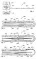
- FIG. 2is a longitudinal cross-sectional view of the distal portion of the device shown in FIG. 1, taken along line 2 — 2 ;
- FIG. 3is a longitudinal cross-sectional view of the distal portion of an alternate arrangement of the device which is part of the system shown in FIG. 1;
- FIG. 4is a longitudinal cross-sectional view of the distal portion of another configuration of the device which is part of the system shown in FIG. 1 .
- cryogenrefers to a fluid substance with properties suitable for: (i) steady flow through ducts of small diameter, (ii) high pressure compression into liquid phase, and (iii) evaporation and expansion to gas phase at low temperatures, typically at saturation temperature or in the range of ⁇ 10 to ⁇ 130 degrees centigrade
- the cryogenmay be any suitable, relatively inert “working fluid”, such as nitrogen, nitrous oxide, or carbon dioxide, or refrigerants such as chlorodifluoromethane, ethyl alcohol, or Freon (a trademark of DuPont), or any number of other refrigerants or fluids with a high thermal energy transfer capacity and low boiling point, as are commonly known to those skilled in the art.
- the term “tube”refers to an elongate duct or conduit suitable for conveying a fluid.
- the tubemay comprise any number of elements or members, and may have a varying range of properties and dimensions, such as length, thickness, and cross-sectional shape.
- downstreamrefers to the relative spatial direction equivalent to the direction of the macroscopic flow of such fluid in such region or space.
- catheterrefers to a medical device composed of any number of tubes and ancillary structures, for insertion into canals, vessels, passageways or other body cavities to permit the treatment of body tissue proximate to the catheter.
- a cathetermay be constructed from a variety of suitable materials having a varying range of structural and thermal properties. It is understood that the particular structural, dimensional, and/or thermal properties of a catheter included in the present invention may considerably vary depending on the particular application of the device disclosed herein.
- FIG. 1a schematic representation of a system constructed in accordance with the principles of the present invention, and designated generally as 100 .
- System 100preferably includes a catheter 101 , a controller unit 102 , and a cryogenic fluid supply 103 .
- the system 100may also include, although the operation of the overall device and invention does not so require, a user interface or console 104 coupled to the controller unit 102 .
- the controller unit 102is preferably composed of any number of suitable mechanical or electronic device components that are capable of receiving and executing programmed instructions, sensor signals, or manual user input as is known in the art.
- the controller unit 102may comprise, without limitation, any of the following components: (i) a computer or microprocessor, (ii) a flow pump and vacuum pump, (iii) a filter or fluid filtration system, (iv) a feedback, closed-loop, or open-loop control system, including all mechanical and electrical components customarily used in such control systems, (v) any number of pressure and temperature sensors, or (vi) any of the commonly used devices for controllably dispensing and receiving fluid flows in a closed-loop flow system wherein the mass flow rate, temperature and pressure of the fluid flow is monitored and regulated.
- the controller unit 102is coupled to the flow of cryogenic fluid from the cryogenic fluid supply 103 , wherein the controller unit 102 then directs and regulates the flow of cryogenic fluid into the catheter 101 .
- the distal portion of the catheter 101is introduced into a body and the distal tip 105 of the catheter 101 is placed in contact with or proximate to selected tissue.
- Cryogenic fluidis then directed to flow to the distal tip 105 , whereupon the fluid undergoes a gas dynamic expansion and evaporation process, thereby cooling the distal tip 105 to low temperatures for selectively cold-treating surrounding tissue.
- the cryogen suppliedmay be either in a liquid or a gaseous state.
- the cryogenis cooled and/or compressed to a predetermined initial temperature and initial pressure before introduction into the catheter 101 .
- the catheter 101contains multiple tubes (not shown), preferably made of flexible or rigid material such a polymer, fiber, metal, or any combination thereof.
- the tubesare arranged to create a plurality of lumens (not shown) for the flow of cryogen therethrough. These lumens are arranged to create a closed-loop circulation path for the flow of cryogen through the device.
- the controller unit 102is used to create vacuum pressure conditions (or negative gauge pressure) at the proximal portion of the return lumen.
- the initial supply pressure of the cryogenis preferably on the order of 30 to 40 atmospheres, or 400 to 600 psia, much higher than the eventual final pressure in the vacuum return lumen.
- the resultant negative pressure gradientdrives the high pressure cryogen drawn from supply 103 to flow through an injection lumen in catheter 101 , to the distal tip 105 , and thereafter to flow back through the return lumen.
- FIG. 2shows a longitudinal cross-sectional view of an exemplary embodiment of the present invention, illustrating, namely, the distal end portion of catheter 101 , and referred to generally as catheter 200 .
- the distal end portion of catheter 200comprises a catheter outer tube 201 , an injection tube 202 , a distal tip 203 , a restriction tube 204 , an expansion chamber 205 , a vacuum buffer layer 206 , seals 207 , and a return lumen 208 .
- the injection tube 202is disposed inside of the outer tube 201 and tip 203 , thereby defining a space occupied by the expansion chamber 205 at the distal end of catheter 200 , and the return lumen 208 at all points proximal from the distal tip.
- the restriction tube 204is coupled proximate the tip 203 , and extends longitudinally parallel to the interior surface of the outer tube 201 , thereby defining the vacuum buffer layer 206 therebetween.
- Tip 203is adhesively coupled to the outer tube 201 by seals 207 . Such seals 207 also couple restriction tube 204 to tip 203 .
- the outer tube element 201circumferentially encloses injection tube 202 and restriction tube 204 , wherein all elements are coaxially disposed with respect to each other, such that a longitudinal centerline (not shown) of outer tube 201 coincides with the longitudinal centerline of both injection tube 202 and restriction tube 204 .
- Restriction tube 204is preferably an annularly shaped body, having a radial symmetry equivalent to that of the outer tube 201 and injection tube 202 .
- the foregoing spatial arrangement of elements 201 , 202 and 204are but one particular arrangement, and that any number of alternative arrangements may be used so as to provide for the suitable operational characteristics of the present invention, as more fully explained below.
- Restriction tube 204is disposed in proximity to the interior surface of outer tube 201 .
- the longitudinal position of restriction tube 204is preferably on the order of one to five catheter diameters proximate from the very distal end of tip 203 .
- the longitudinal length of restriction tube 204is preferably on the order of three to twenty catheter diameters, thereby defining a vacuum buffer layer 206 of similar corresponding longitudinal dimension.
- thermally-transmissive elementis intended to broadly encompass any element that readily conducts heat across a broad range of temperatures, such as from 50 to 500 K.
- the “cooling” power of the deviceis centered around the expansion chamber 205 inside tip 203 .
- tip 203circumferentially encloses the absolute distal end portion of injection tube 202 , thereby defining the expansion chamber 205 therebetween.
- cryogenflows through the injection tube 202 and exits into expansion chamber 205 .
- Cryogen flowing through the injection tube 202is in mixed liquid and gas phase, at several dozen atmospheres pressure and at a temperature equal to or below standard room temperature.
- the cryogenUpon injection into the expansion chamber 205 , the cryogen undergoes two thermodynamic changes: (i) a positive Joule-Thomson throttling process, which may be substantially isenthalpic, but acts to substantially lower the pressure and the temperature of gaseous cryogen; and (ii) a liquid to vapor phase change, wherein the resultant enthalpy of vaporization is absorbed by the cryogen.
- the dual effects of the Joule-Thomson throttling and vaporization of the cryogencomprise the overall cooling mechanism of the device.
- the so-called “cooling power” of the deviceis accordingly a direct function of these thermodynamic changes, and, in particular, is positively correlated to (i) the “quality” of the cryogen supplied, i.e.
- the relative percentage of the cryogen which is in vapor rather than liquid phase(ii) the relative high pressure of the cryogenic fluid supplied, and (iii) the mass flow rate of the cryogenic fluid supplied. If any of the foregoing criteria are diminished, the overall “cooling power” of the device is degraded.
- the corresponding gas dynamic expansion and evaporation of the supplied high-pressure cryogenic fluid in the near field of the expansion chamber 205creates a net flow of low temperature fluid through the expansion chamber 205 .
- This flow of low temperature fluid in the near field of the tip 203causes the temperature of the tip 203 to drop to levels significantly below that of ambient body temperatures, through convective and conductive heat transfer between the tip 203 and the cryogen flow in expansion chamber 205 .
- the low temperature tip 203may then be applied to contact a region of tissue so as to selectively freeze or “cold-treat” the tissue for medical and surgical applications.
- the resulting low pressure, low temperature cryogen gasflows from the expansion chamber 205 through the return lumen 208 , which extends through to the proximal end of catheter body 200 .
- the “spent” cryogenis: (i) vectored back to the controller unit or cryogen supply (not shown) for recycling of the cryogen in a closed-loop flow arrangement, or (ii) discarded from the device in an open-loop flow arrangement.
- the flow properties of the cryogenUpon exiting the injection tube 202 and flowing throughout the return lumen 208 , the flow properties of the cryogen must be regulated to provide for optimal operation of the device.
- the devicemay be operated at various cryogen flow rates. Generally, the cooling power of the device is positively correlated to the cryogen flow rate, which in turn is negatively correlated to the temperatures achieved in the expansion chamber 205 .
- the devicemay used for two specific applications: (i) for “mapping”, wherein the cryogen flow rate is relatively low and the temperature in the distal tip region is relatively high, and (ii) for ablation, wherein the cryogen flow rate is relatively high and the temperature in the in the distal tip region is relatively low.
- the cryogenBy regulating the controller unit to provide a vacuum (less than 14.7 psia) pressure in the return lumen, the cryogen is effectively (i) contained within the catheter body 200 , and (ii) is drawn to flow from the distal end of catheter 200 back to the proximal end and thus “circulates” through the device.
- the cooling power of the deviceis dependent upon achieving the maximum possible pressure and flow rate of cryogen in the expansion chamber 205 .
- the pressure thereinmay be fine-tuned to provide for better performance while still operating within the overall structural limitations of the device.
- the supplied cryogenflows through the distal end of the injection tube 202 and exits into the expansion chamber 205 at a pressure significantly higher than the operating static pressure within the proximal portion of the return lumen 208 .
- This higher pressure in the expansion chamber 205is effectively maintained by the presence of restriction tube 204 inside of the distal portion of the return lumen 208 , just “downstream” of the expansion chamber 205 .
- the overall head loss (and hence the pressure in the expansion chamber 205 ) in the catheter 200may be fine-tuned with a high degree of sensitivity be alternatively placing restriction tubes of various diameter and length inside of the return lumen 208 .
- the length of the restriction tube 204is preferably between 0.50 cm and 125 cm, respectively, while the inside diameter of the return lumen 208 proximate the restriction tube 204 is preferably between 0.025 cm and 0.125 cm.
- the cryogen in the expansion chamber 205may reach its solid-liquid-vapor phase triple point, thereby affecting the temperature stability of the fluid cryogen.
- the pressure in the expansion chambermust be maintained at a level sufficiently high enough to prevent the cryogen from reaching its triple point.
- the restriction tubeeffectively functions as a pressure choking mechanism, while also enabling the fine-tuning of the pressure of the cryogen near the distal tip 203 , thereby broadening the operational applicability of the device.
- the devicehas a high pressure resistance tip with a correspondingly higher cooling power than would be achieved using conventionally designed catheter devices which lack such a restriction tube mechanism.
- the tip 203is coupled to the restriction tube 204 by seals 207 , the bending strength of the distal end of catheter 200 is enhanced. If the catheter 200 were to be kinked at its distal end, the cryogen flow would have to penetrate both (i) the seals 207 bonding the restriction tube 204 with the tip 203 , and (ii) the seals 207 bonding the tip 203 with the outer tube 201 .
- This double sealed tip designprovides for extra protection from leakage and enhances the bending strength of the device structure.
- the catheter 200is typically introduced into a body that is a source of ambient heat, thereby warming the cryogen flowing therethrough and producing significant head losses in the flow of high pressure cryogen in the injection tube 202 , and thus degrading the overall cooling power of the device.
- low temperature cryogen flowing through the return lumen 208convectively “sub-cools” the high pressure cryogen flowing through the injection tube 202 .
- This conductive sub-coolingis enhanced by the increased flow velocity of the cryogen in the restriction tube 204 , thereby counteracting the warming effects of the aforementioned ambient heat sources surrounding the distal end of catheter 200 , where such effects are the most detrimental to the cooling power of the device.
- vacuum buffer layer 206which is an annular space defined between the inner surface of outer body 201 and the outer surface of restriction tube 204 .
- the longitudinal length of vacuum buffer layer 206is approximately equal to the length of the restriction tube 204 . Because the proximal end of vacuum buffer layer 206 is in fluid communication with the return lumen 208 just “downstream” from the restriction tube 204 , the pressure in vacuum buffer layer 206 is at or below atmospheric pressure due to the vacuum provided by the controller unit (not shown). As shown in FIG.
- FIG. 3displays the distal end portion of a catheter body, labeled generally as 300 , including a catheter outer body 301 , an injection tube 302 , a tip 303 , a sleeve 304 , a restriction tube 305 , a expansion chamber 306 , a vacuum buffer layer 307 , a plurality of seals 308 , and a return lumen 309 .
- Cryogenis supplied through the injection tube 302 , whereupon it is injected into the expansion chamber 306 .
- the tip 303is coupled to the outer body 301 and the sleeve 304 with seals 308 .
- the overall spatial arrangement of the injection tube 302 , tip 303 , and restriction tube 305 in the distal portion of the catheter 300is substantially the same as in the corresponding elements displayed in the embodiment of FIG. 2 .
- a sleeve 304is coupled to the proximal end of tip 303 and the distal end of restriction tube 305 .
- the proximal end of restriction tube 305is not shown in FIG. 3, although the length of restriction tube 305 extends longitudinally for approximately 3 to 20 catheter diameters within return lumen 309 .
- Restriction tube 305may also be detachably coupled to sleeve 304 , such that restriction tubes of varying length and diameter may be used to regulate the pressure drop due to head losses occurring in the flow of cryogen therethrough, as more specifically discussed above.
- the sleeve 304is preferably constructed out of a metal or metal alloy, such that it provides sufficient strength to maintain the structural integrity of the tip assembly of catheter 300 . As discussed above, the presence of the sleeve 304 with seals 308 serves to prevent the cryogen flow from leaking out of the device and reinforces the overall bending strength of the distal portion of the catheter 300 .
- FIG. 4shows the distal end portion of catheter 400 , which includes an outer body 401 , an injection tube 402 , a tip 403 , a sleeve 404 , a restriction tube 405 , a return lumen 406 , a vacuum buffer layer 407 , a plurality of seals 408 , and an expansion chamber 409 .
- sleeve 404is structurally fitted to the outer tube 401 and tip 403 .
- the use of multiple seals 408 to bond all of elements 401 , 403 and 404provides increased structural rigidity and pressure strength to the catheter 400 , thereby allowing for greater mass flow through the device, and hence, greater cooling power is achieved.
- the resultant low pressure, low temperature cryogenflows through the return lumen 406 and is successively vectored through the “throat” of the sleeve 404 , such “throat” being the longitudinal position within the return lumen where the cross-sectional area of the return lumen, as dictated by the geometry of the sleeve 404 , is smallest.
- the tapered flow of cryogen through the sleeve 404further accelerates the low pressure cryogen flow through the return lumen 406 , thereby causing “gradual” (as opposed to sudden) contraction and expansion head losses, as is well known to those skilled in the art.
- the sleeve 404may be composed of a thermally conductive material and coupled to the tip 403 , so that the flow of low temperature cryogen through the sleeve 404 further creates additional net heat transfer from the tip 403 to the cryogen flowing through the return lumen 406 . This enhances the “cooling power” of the device beyond that contemplated and discussed in the previous embodiments.
- All of the various components of the present inventionare constructed from polyimide or some other suitable polymer based material, having sufficient rigidity to enable the effective operation of the device.
- Other materials which may be usedinclude Teflon® brand tubing and coatings, polyurethane, silicone, or nylon.
Landscapes
- Health & Medical Sciences (AREA)
- Surgery (AREA)
- Life Sciences & Earth Sciences (AREA)
- Nuclear Medicine, Radiotherapy & Molecular Imaging (AREA)
- Medical Informatics (AREA)
- General Health & Medical Sciences (AREA)
- Biomedical Technology (AREA)
- Heart & Thoracic Surgery (AREA)
- Otolaryngology (AREA)
- Molecular Biology (AREA)
- Animal Behavior & Ethology (AREA)
- Engineering & Computer Science (AREA)
- Public Health (AREA)
- Veterinary Medicine (AREA)
- Surgical Instruments (AREA)
- Thermotherapy And Cooling Therapy Devices (AREA)
- Media Introduction/Drainage Providing Device (AREA)
- Dental Preparations (AREA)
- Materials For Medical Uses (AREA)
Abstract
Description
Claims (18)
Priority Applications (6)
| Application Number | Priority Date | Filing Date | Title |
|---|---|---|---|
| US09/965,208US6589234B2 (en) | 2001-09-27 | 2001-09-27 | Cryogenic medical device with high pressure resistance tip |
| DE60231891TDE60231891D1 (en) | 2001-09-27 | 2002-09-23 | KRYOGENE MEDICAL DEVICE WITH HIGH-PRESSURE FINISH |
| EP02767804AEP1432363B1 (en) | 2001-09-27 | 2002-09-23 | Cryogenic medical device with high pressure resistance tip |
| CA002459771ACA2459771C (en) | 2001-09-27 | 2002-09-23 | Cryogenic medical device with high pressure resistance tip |
| PCT/IB2002/003931WO2003028569A1 (en) | 2001-09-27 | 2002-09-23 | Cryogenic medical device with high pressure resistance tip |
| AT02767804TATE427710T1 (en) | 2001-09-27 | 2002-09-23 | CRYOGENIC MEDICAL DEVICE WITH HIGH PRESSURE RESISTANT END PIECE |
Applications Claiming Priority (1)
| Application Number | Priority Date | Filing Date | Title |
|---|---|---|---|
| US09/965,208US6589234B2 (en) | 2001-09-27 | 2001-09-27 | Cryogenic medical device with high pressure resistance tip |
Publications (2)
| Publication Number | Publication Date |
|---|---|
| US20030060815A1 US20030060815A1 (en) | 2003-03-27 |
| US6589234B2true US6589234B2 (en) | 2003-07-08 |
Family
ID=25509635
Family Applications (1)
| Application Number | Title | Priority Date | Filing Date |
|---|---|---|---|
| US09/965,208Expired - LifetimeUS6589234B2 (en) | 2001-09-27 | 2001-09-27 | Cryogenic medical device with high pressure resistance tip |
Country Status (6)
| Country | Link |
|---|---|
| US (1) | US6589234B2 (en) |
| EP (1) | EP1432363B1 (en) |
| AT (1) | ATE427710T1 (en) |
| CA (1) | CA2459771C (en) |
| DE (1) | DE60231891D1 (en) |
| WO (1) | WO2003028569A1 (en) |
Cited By (47)
| Publication number | Priority date | Publication date | Assignee | Title |
|---|---|---|---|---|
| US20030220634A1 (en)* | 2000-08-09 | 2003-11-27 | Ryba Eric L. | Refrigeration source for a cryoablation catheter |
| US20040024413A1 (en)* | 2002-07-31 | 2004-02-05 | Lentz David J. | Wire reinforced articulation segment |
| US20040034344A1 (en)* | 2002-08-16 | 2004-02-19 | Eric Ryba | Tip pressure monitoring for cryoablation catheters |
| US20040034345A1 (en)* | 2002-08-16 | 2004-02-19 | Lentz David J. | Heat transfer segment for a cryoablation catheter |
| US20040034365A1 (en)* | 2002-08-16 | 2004-02-19 | Lentz David J. | Catheter having articulation system |
| US20040116921A1 (en)* | 2002-12-11 | 2004-06-17 | Marshall Sherman | Cold tip rf/ultrasonic ablation catheter |
| US20040116916A1 (en)* | 2002-12-11 | 2004-06-17 | Lentz David J. | Coaxial catheter system for performing a single step cryoablation |
| US20040116917A1 (en)* | 2002-12-11 | 2004-06-17 | Lentz David J. | System and method for performing a single step cryoablation |
| US6824543B2 (en) | 2002-12-11 | 2004-11-30 | Cryocor, Inc. | Guidance system for a cryocatheter |
| US20040243118A1 (en)* | 2001-06-01 | 2004-12-02 | Ayers Gregory M. | Device and method for positioning a catheter tip for creating a cryogenic lesion |
| US20050016188A1 (en)* | 2003-07-24 | 2005-01-27 | Lentz David J. | Distal end for cryoablation catheters |
| US20050027289A1 (en)* | 2003-07-31 | 2005-02-03 | Thomas Castellano | Cryoablation systems and methods |
| US20050177146A1 (en)* | 2004-02-10 | 2005-08-11 | Marshall Sherman | System and method for assessing ice ball formation during a cryoablation procedure |
| US20050198972A1 (en)* | 2004-03-10 | 2005-09-15 | Lentz David J. | Pressure-temperature control for a cryoablation catheter system |
| US20050261671A1 (en)* | 2001-05-31 | 2005-11-24 | Baust John G | Cryogenic system |
| US20050283146A1 (en)* | 2004-06-17 | 2005-12-22 | Lentz David J | Thermally extended spiral cryotip for a cryoablation catheter |
| US20050288657A1 (en)* | 2004-06-29 | 2005-12-29 | Lentz David J | Pressure monitor for cryoablation catheter |
| US20060004349A1 (en)* | 2004-06-30 | 2006-01-05 | Eric Ryba | System for detecting leaks and occlusions in a cryoablation catheter |
| US20060147245A1 (en)* | 2004-12-30 | 2006-07-06 | Carl Cetera | Implement grip |
| US20060258981A1 (en)* | 2005-04-27 | 2006-11-16 | Tracee Eidenschink | Balloon catheter with perfusion lumen |
| US20070060918A1 (en)* | 2005-08-22 | 2007-03-15 | Holman Thomas J | Local perfusion device |
| US7195625B2 (en) | 2002-12-11 | 2007-03-27 | Cryocor, Inc. | Catheter system for performing a single step cryoablation |
| US20070129682A1 (en)* | 2005-12-02 | 2007-06-07 | Tracee Eidenschink | Guidewire with perfusion capability |
| US7357797B2 (en) | 2004-06-30 | 2008-04-15 | Cryocor, Inc. | System and method for varying return pressure to control tip temperature of a cryoablation catheter |
| US20080306475A1 (en)* | 2007-06-08 | 2008-12-11 | Lentz David J | Cryo-applicator cross-section configuration |
| US20090018504A1 (en)* | 2005-12-22 | 2009-01-15 | John Pile-Spellman | Systems and methods for intravascular cooling |
| US20090287201A1 (en)* | 2008-05-16 | 2009-11-19 | Jean-Pierre Lalonde | Thermocouple-controlled catether cooling system |
| US20090299357A1 (en)* | 2006-04-24 | 2009-12-03 | Thomas Jefferson University | Cryoneedle and cryotheraphy system |
| US7799019B2 (en) | 2005-05-10 | 2010-09-21 | Vivant Medical, Inc. | Reinforced high strength microwave antenna |
| US20100305559A1 (en)* | 2009-05-27 | 2010-12-02 | Vivant Medical, Inc. | Narrow Gauge High Strength Choked Wet Tip Microwave Ablation Antenna |
| US7862559B2 (en) | 2001-11-02 | 2011-01-04 | Vivant Medical, Inc. | High-strength microwave antenna assemblies and methods of use |
| US7998139B2 (en) | 2007-04-25 | 2011-08-16 | Vivant Medical, Inc. | Cooled helical antenna for microwave ablation |
| WO2011151354A2 (en) | 2010-06-01 | 2011-12-08 | Afreeze Gmbh | Leakage protection system, pressure balancing system, and precipitator with valve function for ablation applications |
| US20120123413A1 (en)* | 2010-11-17 | 2012-05-17 | Tyco Healthcare Group Lp | Method and Apparatus for Vascular Tissue Sealing with Active Cooling of Jaws at the End of the Sealing Cycle |
| US20120265452A1 (en)* | 2011-04-14 | 2012-10-18 | Galil Medical Inc. | Method of monitoring gas supply during a cryosurgical procedure |
| US8353901B2 (en) | 2007-05-22 | 2013-01-15 | Vivant Medical, Inc. | Energy delivery conduits for use with electrosurgical devices |
| WO2013007831A1 (en) | 2011-07-14 | 2013-01-17 | Afreeze Gmbh | Ablation applicator with a matrix filled with particles |
| US20130041355A1 (en)* | 2011-08-11 | 2013-02-14 | Tammo Heeren | Reducing Damage From A Dielectric Breakdown in Surgical Applications |
| US20130253497A1 (en)* | 2012-03-26 | 2013-09-26 | Mark Chak | Needle for treating diseases |
| US8651146B2 (en) | 2007-09-28 | 2014-02-18 | Covidien Lp | Cable stand-off |
| US20140074081A1 (en)* | 2011-02-01 | 2014-03-13 | Channel Medsystems, Inc. | Cyrogenic treatment systems |
| US9023024B2 (en) | 2007-06-20 | 2015-05-05 | Covidien Lp | Reflective power monitoring for microwave applications |
| US9468499B2 (en) | 2003-07-18 | 2016-10-18 | Covidien Lp | Devices and methods for cooling microwave antennas |
| US9549779B2 (en) | 2001-11-02 | 2017-01-24 | Covidien Lp | High-strength microwave antenna assemblies |
| WO2020028282A1 (en)* | 2018-08-01 | 2020-02-06 | Adagio Medical, Inc. | Ablation catheter having an expandable treatment portion |
| US10610279B2 (en) | 2014-04-10 | 2020-04-07 | Channel Medsystems, Inc. | Apparatus and methods for regulating cryogenic treatment |
| US11103296B2 (en) | 2011-07-14 | 2021-08-31 | Afreeze Gmbh | Ablation applicator with a matrix filled with particles |
Families Citing this family (12)
| Publication number | Priority date | Publication date | Assignee | Title |
|---|---|---|---|---|
| DE102008045563B9 (en)* | 2008-07-02 | 2012-01-26 | Erbe Elektromedizin Gmbh | Temperature control for a cryoprobe, cryosurgical device with temperature controller and method for controlling the temperature of a cryoprobe |
| US10363057B2 (en) | 2008-07-18 | 2019-07-30 | Vytronus, Inc. | System and method for delivering energy to tissue |
| DE102011000004B4 (en)* | 2010-12-08 | 2015-02-19 | Erbe Elektromedizin Gmbh | gas nozzle |
| US11020098B2 (en)* | 2014-09-09 | 2021-06-01 | Boston Scientific Scimed, Inc. | Methods, systems and devices for cryogenic biopsy |
| US11033319B2 (en)* | 2014-12-01 | 2021-06-15 | Vesica E.K. Therapeutics Ltd. | Device and method for ablative treatment of targeted areas within a body lumen |
| EP3349676A4 (en)* | 2015-09-18 | 2019-05-15 | Adagio Medical, Inc. | TISSUE CONTACT VERIFICATION SYSTEM |
| CN109922749B (en)* | 2016-11-09 | 2021-10-12 | 奥林巴斯株式会社 | Medical device |
| US11628007B2 (en)* | 2018-09-14 | 2023-04-18 | Atricure, Inc. | Cryoprobe |
| WO2020092981A1 (en)* | 2018-11-01 | 2020-05-07 | Biocompatibles Uk Limited | Cryoprobe with stiffening element |
| AU2020245381A1 (en)* | 2019-03-25 | 2021-11-04 | Biocompatibles Uk Limited | Cryoprobe |
| CN114173690A (en)* | 2019-05-30 | 2022-03-11 | 阿特菲克斯有限公司 | Cryoablation catheter |
| AU2020330099B2 (en)* | 2019-08-14 | 2024-02-01 | Biocompatibles Uk Limited | Flexible cryoprobe |
Citations (25)
| Publication number | Priority date | Publication date | Assignee | Title |
|---|---|---|---|---|
| US3425419A (en) | 1964-08-08 | 1969-02-04 | Angelo Actis Dato | Method of lowering and raising the temperature of the human body |
| US3859986A (en) | 1973-06-20 | 1975-01-14 | Jiro Okada | Surgical device |
| US3948269A (en) | 1973-08-31 | 1976-04-06 | Dragerwerk Aktiengesellschaft | Cryomedical device |
| WO1983003961A1 (en) | 1982-05-17 | 1983-11-24 | Andrzej Kamil Drukier | Cryoprobes, especially for the cryosurgery of deeply lying lesions |
| US4946460A (en) | 1989-04-26 | 1990-08-07 | Cryo Instruments, Inc. | Apparatus for cryosurgery |
| US5078713A (en) | 1988-12-01 | 1992-01-07 | Spembly Medical Limited | Cryosurgical probe |
| US5211646A (en) | 1990-03-09 | 1993-05-18 | Alperovich Boris I | Cryogenic scalpel |
| US5275595A (en) | 1992-07-06 | 1994-01-04 | Dobak Iii John D | Cryosurgical instrument |
| US5281215A (en) | 1992-04-16 | 1994-01-25 | Implemed, Inc. | Cryogenic catheter |
| US5281213A (en) | 1992-04-16 | 1994-01-25 | Implemed, Inc. | Catheter for ice mapping and ablation |
| US5324286A (en) | 1993-01-21 | 1994-06-28 | Arthur A. Fowle, Inc. | Entrained cryogenic droplet transfer method and cryosurgical instrument |
| US5403309A (en) | 1992-07-31 | 1995-04-04 | Spembly Medical Limited | Cryosurgical ablation |
| US5423807A (en) | 1992-04-16 | 1995-06-13 | Implemed, Inc. | Cryogenic mapping and ablation catheter |
| US5520682A (en)* | 1991-09-06 | 1996-05-28 | Cryomedical Sciences, Inc. | Cryosurgical instrument with vent means and method using same |
| US5573532A (en) | 1995-01-13 | 1996-11-12 | Cryomedical Sciences, Inc. | Cryogenic surgical instrument and method of manufacturing the same |
| US5624392A (en) | 1990-05-11 | 1997-04-29 | Saab; Mark A. | Heat transfer catheters and methods of making and using same |
| US5716353A (en) | 1996-05-03 | 1998-02-10 | Urds, Corp. | Cryosurgical instrument |
| US5759182A (en) | 1993-11-09 | 1998-06-02 | Spembly Medical Limited | Cryosurgical probe with pre-cooling feature |
| US5800488A (en) | 1996-07-23 | 1998-09-01 | Endocare, Inc. | Cryoprobe with warming feature |
| US5833685A (en) | 1994-03-15 | 1998-11-10 | Tortal; Proserfina R. | Cryosurgical technique and devices |
| US5860970A (en) | 1994-05-10 | 1999-01-19 | Spembly Medical Limited | Cryosurgical instrument |
| US5885276A (en) | 1997-12-02 | 1999-03-23 | Galil Medical Ltd. | Method and device for transmyocardial cryo revascularization |
| US5992158A (en) | 1994-05-10 | 1999-11-30 | Spembly Medical Limited | Cryosurgical instrument |
| EP1129670A1 (en) | 2000-03-02 | 2001-09-05 | Biosense Webster, Inc. | Cryoablation catheter for long lesion ablations |
| US6319248B1 (en)* | 1998-07-29 | 2001-11-20 | Cryocath Technologies, Inc. | Spray catheter |
Family Cites Families (1)
| Publication number | Priority date | Publication date | Assignee | Title |
|---|---|---|---|---|
| US5254116A (en)* | 1991-09-06 | 1993-10-19 | Cryomedical Sciences, Inc. | Cryosurgical instrument with vent holes and method using same |
- 2001
- 2001-09-27USUS09/965,208patent/US6589234B2/ennot_activeExpired - Lifetime
- 2002
- 2002-09-23WOPCT/IB2002/003931patent/WO2003028569A1/ennot_activeApplication Discontinuation
- 2002-09-23EPEP02767804Apatent/EP1432363B1/ennot_activeExpired - Lifetime
- 2002-09-23DEDE60231891Tpatent/DE60231891D1/ennot_activeExpired - Lifetime
- 2002-09-23CACA002459771Apatent/CA2459771C/ennot_activeExpired - Fee Related
- 2002-09-23ATAT02767804Tpatent/ATE427710T1/ennot_activeIP Right Cessation
Patent Citations (26)
| Publication number | Priority date | Publication date | Assignee | Title |
|---|---|---|---|---|
| US3425419A (en) | 1964-08-08 | 1969-02-04 | Angelo Actis Dato | Method of lowering and raising the temperature of the human body |
| US3859986A (en) | 1973-06-20 | 1975-01-14 | Jiro Okada | Surgical device |
| US3948269A (en) | 1973-08-31 | 1976-04-06 | Dragerwerk Aktiengesellschaft | Cryomedical device |
| WO1983003961A1 (en) | 1982-05-17 | 1983-11-24 | Andrzej Kamil Drukier | Cryoprobes, especially for the cryosurgery of deeply lying lesions |
| US5078713A (en) | 1988-12-01 | 1992-01-07 | Spembly Medical Limited | Cryosurgical probe |
| US4946460A (en) | 1989-04-26 | 1990-08-07 | Cryo Instruments, Inc. | Apparatus for cryosurgery |
| US5211646A (en) | 1990-03-09 | 1993-05-18 | Alperovich Boris I | Cryogenic scalpel |
| US5624392A (en) | 1990-05-11 | 1997-04-29 | Saab; Mark A. | Heat transfer catheters and methods of making and using same |
| US5520682A (en)* | 1991-09-06 | 1996-05-28 | Cryomedical Sciences, Inc. | Cryosurgical instrument with vent means and method using same |
| US5423807A (en) | 1992-04-16 | 1995-06-13 | Implemed, Inc. | Cryogenic mapping and ablation catheter |
| US5281213A (en) | 1992-04-16 | 1994-01-25 | Implemed, Inc. | Catheter for ice mapping and ablation |
| US5281215A (en) | 1992-04-16 | 1994-01-25 | Implemed, Inc. | Cryogenic catheter |
| US5275595A (en) | 1992-07-06 | 1994-01-04 | Dobak Iii John D | Cryosurgical instrument |
| US5403309A (en) | 1992-07-31 | 1995-04-04 | Spembly Medical Limited | Cryosurgical ablation |
| US5324286A (en) | 1993-01-21 | 1994-06-28 | Arthur A. Fowle, Inc. | Entrained cryogenic droplet transfer method and cryosurgical instrument |
| US5759182A (en) | 1993-11-09 | 1998-06-02 | Spembly Medical Limited | Cryosurgical probe with pre-cooling feature |
| US5833685A (en) | 1994-03-15 | 1998-11-10 | Tortal; Proserfina R. | Cryosurgical technique and devices |
| US5860970A (en) | 1994-05-10 | 1999-01-19 | Spembly Medical Limited | Cryosurgical instrument |
| US5992158A (en) | 1994-05-10 | 1999-11-30 | Spembly Medical Limited | Cryosurgical instrument |
| US5573532A (en) | 1995-01-13 | 1996-11-12 | Cryomedical Sciences, Inc. | Cryogenic surgical instrument and method of manufacturing the same |
| US5716353A (en) | 1996-05-03 | 1998-02-10 | Urds, Corp. | Cryosurgical instrument |
| US5800488A (en) | 1996-07-23 | 1998-09-01 | Endocare, Inc. | Cryoprobe with warming feature |
| US5800487A (en) | 1996-07-23 | 1998-09-01 | Endocare, Inc. | Cryoprobe |
| US5885276A (en) | 1997-12-02 | 1999-03-23 | Galil Medical Ltd. | Method and device for transmyocardial cryo revascularization |
| US6319248B1 (en)* | 1998-07-29 | 2001-11-20 | Cryocath Technologies, Inc. | Spray catheter |
| EP1129670A1 (en) | 2000-03-02 | 2001-09-05 | Biosense Webster, Inc. | Cryoablation catheter for long lesion ablations |
Cited By (117)
| Publication number | Priority date | Publication date | Assignee | Title |
|---|---|---|---|---|
| USRE40868E1 (en) | 1999-06-25 | 2009-08-11 | Cryocor, Inc. | Refrigeration source for a cryoblation catheter |
| US20030220634A1 (en)* | 2000-08-09 | 2003-11-27 | Ryba Eric L. | Refrigeration source for a cryoablation catheter |
| US7004936B2 (en) | 2000-08-09 | 2006-02-28 | Cryocor, Inc. | Refrigeration source for a cryoablation catheter |
| US20050261671A1 (en)* | 2001-05-31 | 2005-11-24 | Baust John G | Cryogenic system |
| US20090043297A1 (en)* | 2001-05-31 | 2009-02-12 | Endocare, Inc. | Cryogenic system |
| US8551081B2 (en) | 2001-05-31 | 2013-10-08 | Endocare, Inc. | Cryogenic system |
| US7416548B2 (en) | 2001-05-31 | 2008-08-26 | Endocare, Inc. | Cryogenic system |
| US20070213699A1 (en)* | 2001-05-31 | 2007-09-13 | Endocare, Inc. | Cryogenic system |
| US7192426B2 (en)* | 2001-05-31 | 2007-03-20 | Endocare, Inc. | Cryogenic system |
| US20040243118A1 (en)* | 2001-06-01 | 2004-12-02 | Ayers Gregory M. | Device and method for positioning a catheter tip for creating a cryogenic lesion |
| US9549779B2 (en) | 2001-11-02 | 2017-01-24 | Covidien Lp | High-strength microwave antenna assemblies |
| US7862559B2 (en) | 2001-11-02 | 2011-01-04 | Vivant Medical, Inc. | High-strength microwave antenna assemblies and methods of use |
| US9579152B2 (en) | 2001-11-02 | 2017-02-28 | Covidien Lp | High-strength microwave antenna assemblies |
| US10154880B2 (en) | 2001-11-02 | 2018-12-18 | Covidien Lp | High-strength microwave antenna assemblies |
| US7004937B2 (en) | 2002-07-31 | 2006-02-28 | Cryocor, Inc. | Wire reinforced articulation segment |
| US20040024413A1 (en)* | 2002-07-31 | 2004-02-05 | Lentz David J. | Wire reinforced articulation segment |
| US20040034344A1 (en)* | 2002-08-16 | 2004-02-19 | Eric Ryba | Tip pressure monitoring for cryoablation catheters |
| US20040034345A1 (en)* | 2002-08-16 | 2004-02-19 | Lentz David J. | Heat transfer segment for a cryoablation catheter |
| US20040034365A1 (en)* | 2002-08-16 | 2004-02-19 | Lentz David J. | Catheter having articulation system |
| US6955673B2 (en) | 2002-08-16 | 2005-10-18 | Cryocor, Inc. | Heat transfer segment for a cryoablation catheter |
| US7195625B2 (en) | 2002-12-11 | 2007-03-27 | Cryocor, Inc. | Catheter system for performing a single step cryoablation |
| US20040116917A1 (en)* | 2002-12-11 | 2004-06-17 | Lentz David J. | System and method for performing a single step cryoablation |
| US20040116921A1 (en)* | 2002-12-11 | 2004-06-17 | Marshall Sherman | Cold tip rf/ultrasonic ablation catheter |
| US6796979B2 (en) | 2002-12-11 | 2004-09-28 | Cryocor, Inc. | Coaxial catheter system for performing a single step cryoablation |
| US6824543B2 (en) | 2002-12-11 | 2004-11-30 | Cryocor, Inc. | Guidance system for a cryocatheter |
| US20040116916A1 (en)* | 2002-12-11 | 2004-06-17 | Lentz David J. | Coaxial catheter system for performing a single step cryoablation |
| US6893433B2 (en) | 2002-12-11 | 2005-05-17 | Cryocor, Inc. | System and method for performing a single step cryoablation |
| US10405921B2 (en) | 2003-07-18 | 2019-09-10 | Covidien Lp | Devices and methods for cooling microwave antennas |
| US9820814B2 (en) | 2003-07-18 | 2017-11-21 | Covidien Lp | Devices and methods for cooling microwave antennas |
| US9480528B2 (en) | 2003-07-18 | 2016-11-01 | Covidien Lp | Devices and methods for cooling microwave antennas |
| US9468499B2 (en) | 2003-07-18 | 2016-10-18 | Covidien Lp | Devices and methods for cooling microwave antennas |
| US20050016188A1 (en)* | 2003-07-24 | 2005-01-27 | Lentz David J. | Distal end for cryoablation catheters |
| US6981382B2 (en)* | 2003-07-24 | 2006-01-03 | Cryocor, Inc. | Distal end for cryoablation catheters |
| US20050027289A1 (en)* | 2003-07-31 | 2005-02-03 | Thomas Castellano | Cryoablation systems and methods |
| US7070594B2 (en) | 2004-02-10 | 2006-07-04 | Cryocor, Inc. | System and method for assessing ice ball formation during a cryoablation procedure |
| US20050177146A1 (en)* | 2004-02-10 | 2005-08-11 | Marshall Sherman | System and method for assessing ice ball formation during a cryoablation procedure |
| US20050198972A1 (en)* | 2004-03-10 | 2005-09-15 | Lentz David J. | Pressure-temperature control for a cryoablation catheter system |
| US20050283146A1 (en)* | 2004-06-17 | 2005-12-22 | Lentz David J | Thermally extended spiral cryotip for a cryoablation catheter |
| US7156840B2 (en) | 2004-06-29 | 2007-01-02 | Cryocor, Inc. | Pressure monitor for cryoablation catheter |
| US20050288657A1 (en)* | 2004-06-29 | 2005-12-29 | Lentz David J | Pressure monitor for cryoablation catheter |
| US7163535B2 (en) | 2004-06-30 | 2007-01-16 | Cryocor, Inc. | System for detecting leaks and occlusions in a cryoablation catheter |
| US20060004349A1 (en)* | 2004-06-30 | 2006-01-05 | Eric Ryba | System for detecting leaks and occlusions in a cryoablation catheter |
| US7357797B2 (en) | 2004-06-30 | 2008-04-15 | Cryocor, Inc. | System and method for varying return pressure to control tip temperature of a cryoablation catheter |
| US20060147245A1 (en)* | 2004-12-30 | 2006-07-06 | Carl Cetera | Implement grip |
| US20060258981A1 (en)* | 2005-04-27 | 2006-11-16 | Tracee Eidenschink | Balloon catheter with perfusion lumen |
| US8012148B2 (en) | 2005-05-10 | 2011-09-06 | Vivant Medical, Inc. | Reinforced high strength microwave antenna |
| US9186216B2 (en) | 2005-05-10 | 2015-11-17 | Covidien Lp | Reinforced high strength microwave antenna |
| US8663213B2 (en) | 2005-05-10 | 2014-03-04 | Covidien Lp | Reinforced high strength microwave antenna |
| US8192423B2 (en) | 2005-05-10 | 2012-06-05 | Vivant Medical, Inc. | Reinforced high strength microwave antenna |
| US10537386B2 (en) | 2005-05-10 | 2020-01-21 | Covidien Lp | Reinforced high strength microwave antenna |
| US11717347B2 (en) | 2005-05-10 | 2023-08-08 | Covidien Lp | Reinforced high strength microwave antenna |
| US8974452B2 (en) | 2005-05-10 | 2015-03-10 | Covidien Lp | Reinforced high strength microwave antenna |
| US7799019B2 (en) | 2005-05-10 | 2010-09-21 | Vivant Medical, Inc. | Reinforced high strength microwave antenna |
| US20070060918A1 (en)* | 2005-08-22 | 2007-03-15 | Holman Thomas J | Local perfusion device |
| US7963940B2 (en) | 2005-08-22 | 2011-06-21 | Boston Scientific Scimed, Inc. | Local perfusion device |
| US20070129682A1 (en)* | 2005-12-02 | 2007-06-07 | Tracee Eidenschink | Guidewire with perfusion capability |
| US8343097B2 (en) | 2005-12-22 | 2013-01-01 | Hybernia Medical Llc | Systems and methods for intravascular cooling |
| US20090018504A1 (en)* | 2005-12-22 | 2009-01-15 | John Pile-Spellman | Systems and methods for intravascular cooling |
| US20090299357A1 (en)* | 2006-04-24 | 2009-12-03 | Thomas Jefferson University | Cryoneedle and cryotheraphy system |
| US7998139B2 (en) | 2007-04-25 | 2011-08-16 | Vivant Medical, Inc. | Cooled helical antenna for microwave ablation |
| US9808313B2 (en) | 2007-05-22 | 2017-11-07 | Covidien Lp | Energy delivery conduits for use with electrosurgical devices |
| US8353901B2 (en) | 2007-05-22 | 2013-01-15 | Vivant Medical, Inc. | Energy delivery conduits for use with electrosurgical devices |
| US8628523B2 (en) | 2007-05-22 | 2014-01-14 | Covidien Lp | Energy delivery conduits for use with electrosurgical devices |
| US9301802B2 (en) | 2007-05-22 | 2016-04-05 | Covidien Lp | Energy delivery conduits for use with electrosurgical devices |
| US10271903B2 (en) | 2007-05-22 | 2019-04-30 | Covidien Lp | Energy delivery conduits for use with electrosurgical devices |
| US20080306475A1 (en)* | 2007-06-08 | 2008-12-11 | Lentz David J | Cryo-applicator cross-section configuration |
| US20130158533A1 (en)* | 2007-06-08 | 2013-06-20 | Boston Scientific Scimed, Inc. | Cryo-applicator cross-section configuration |
| US8377050B2 (en)* | 2007-06-08 | 2013-02-19 | Boston Scientific Scimed, Inc. | Cryo-applicator cross-section configuration |
| US10987165B2 (en) | 2007-06-20 | 2021-04-27 | Covidien Lp | Reflective power monitoring for microwave applications |
| US9827043B2 (en) | 2007-06-20 | 2017-11-28 | Covidien Lp | Reflective power monitoring for microwave applications |
| US9023024B2 (en) | 2007-06-20 | 2015-05-05 | Covidien Lp | Reflective power monitoring for microwave applications |
| US8651146B2 (en) | 2007-09-28 | 2014-02-18 | Covidien Lp | Cable stand-off |
| US9050069B2 (en)* | 2008-05-16 | 2015-06-09 | Medtronic Cryocath Lp | Thermocouple-controlled catheter cooling system |
| US20090287201A1 (en)* | 2008-05-16 | 2009-11-19 | Jean-Pierre Lalonde | Thermocouple-controlled catether cooling system |
| US11026739B2 (en) | 2008-05-16 | 2021-06-08 | Medronic CryoCath LP | Thermocouple-controlled catheter cooling system |
| US9936998B2 (en) | 2008-05-16 | 2018-04-10 | Medtronic Cryocath Lp | Thermocouple-controlled catheter cooling system |
| US12042204B2 (en) | 2008-05-16 | 2024-07-23 | Medtronic Cryocath Lp | Thermocouple-controlled catheter cooling system |
| US9192437B2 (en) | 2009-05-27 | 2015-11-24 | Covidien Lp | Narrow gauge high strength choked wet tip microwave ablation antenna |
| US10499989B2 (en) | 2009-05-27 | 2019-12-10 | Covidien Lp | Narrow gauge high strength choked wet tip microwave ablation antenna |
| US20100305559A1 (en)* | 2009-05-27 | 2010-12-02 | Vivant Medical, Inc. | Narrow Gauge High Strength Choked Wet Tip Microwave Ablation Antenna |
| US8292881B2 (en) | 2009-05-27 | 2012-10-23 | Vivant Medical, Inc. | Narrow gauge high strength choked wet tip microwave ablation antenna |
| US9662172B2 (en) | 2009-05-27 | 2017-05-30 | Covidien Lp | Narrow gauge high strength choked wet tip microwave ablation antenna |
| US9662162B2 (en) | 2010-06-01 | 2017-05-30 | Afreeze Gmbh | Leakage protection system, pressure balancing system, and precipitator with valve function for ablation applications |
| EP3281594A1 (en) | 2010-06-01 | 2018-02-14 | AFreeze GmbH | Leakage protection system, pressure balancing system, and precipitator with valve function for ablation applications |
| US10660689B2 (en) | 2010-06-01 | 2020-05-26 | Afreeze Gmbh | Leakage protection system, pressure balancing system, and precipitator with valve function for ablation applications |
| WO2011151354A2 (en) | 2010-06-01 | 2011-12-08 | Afreeze Gmbh | Leakage protection system, pressure balancing system, and precipitator with valve function for ablation applications |
| US8685021B2 (en)* | 2010-11-17 | 2014-04-01 | Covidien Lp | Method and apparatus for vascular tissue sealing with active cooling of jaws at the end of the sealing cycle |
| US20120123413A1 (en)* | 2010-11-17 | 2012-05-17 | Tyco Healthcare Group Lp | Method and Apparatus for Vascular Tissue Sealing with Active Cooling of Jaws at the End of the Sealing Cycle |
| US10959879B2 (en) | 2011-02-01 | 2021-03-30 | Channel Medsystems, Inc. | Methods and apparatus for cryogenic treatment of a body cavity or lumen |
| US9445860B2 (en) | 2011-02-01 | 2016-09-20 | Channel Medsystems, Inc. | Handheld cyrogenic treatment systems |
| US8858543B2 (en) | 2011-02-01 | 2014-10-14 | Channel Medsystems, Inc. | Cyrogenic treatment systems |
| US11883324B2 (en) | 2011-02-01 | 2024-01-30 | Channel Medsystems, Inc. | Cryogenic treatment systems |
| US9486267B2 (en) | 2011-02-01 | 2016-11-08 | Channel Medsystems, Inc. | Cryogenic treatment systems |
| US11833076B2 (en) | 2011-02-01 | 2023-12-05 | Channel Medsystems, Inc. | Methods and apparatus for cryogenic treatment of a body cavity or lumen |
| US9848933B2 (en) | 2011-02-01 | 2017-12-26 | Channel Medsystems, Inc. | Liner for cryogenic treatment systems |
| US9603650B2 (en) | 2011-02-01 | 2017-03-28 | Channel Medsystems, Inc. | Cryogenic treatment systems |
| US9492217B2 (en) | 2011-02-01 | 2016-11-15 | Channel Medsystems, Inc. | Treatments using cryogenic ablation systems |
| US9498274B2 (en) | 2011-02-01 | 2016-11-22 | Channel Medsystems, Inc. | Liner extraction methods |
| US9517100B2 (en) | 2011-02-01 | 2016-12-13 | Channel Medsystems, Inc. | Cryogenic treatment methods |
| US10213335B2 (en) | 2011-02-01 | 2019-02-26 | Channel Medsystems, Inc. | Methods and apparatus for cryogenic treatment of a body cavity or lumen |
| US9510887B2 (en) | 2011-02-01 | 2016-12-06 | Channel Medsystems, Inc. | Time-limited methods for cryogenic treatment systems |
| US9492218B2 (en) | 2011-02-01 | 2016-11-15 | Channel Medsystems, Inc. | Pressure monitoring systems |
| US9408657B2 (en)* | 2011-02-01 | 2016-08-09 | Channel Medsystems, Inc. | Cryogenic treatment systems |
| US9283022B2 (en) | 2011-02-01 | 2016-03-15 | Channel Medsystems, Inc. | Methods and apparatus for cryogenic treatment of a body cavity or lumen |
| US20140074081A1 (en)* | 2011-02-01 | 2014-03-13 | Channel Medsystems, Inc. | Cyrogenic treatment systems |
| US9277952B2 (en) | 2011-02-01 | 2016-03-08 | Channel Medsystems, Inc. | Cryogenic treatment systems |
| US20120265452A1 (en)* | 2011-04-14 | 2012-10-18 | Galil Medical Inc. | Method of monitoring gas supply during a cryosurgical procedure |
| US9918772B2 (en) | 2011-07-14 | 2018-03-20 | Afreeze Gmbh | Ablation applicator with a matrix filled with particles |
| US11103296B2 (en) | 2011-07-14 | 2021-08-31 | Afreeze Gmbh | Ablation applicator with a matrix filled with particles |
| WO2013007831A1 (en) | 2011-07-14 | 2013-01-17 | Afreeze Gmbh | Ablation applicator with a matrix filled with particles |
| US12076068B2 (en) | 2011-07-14 | 2024-09-03 | Afreeze Gmbh | Ablation applicator with a matrix filled with particles |
| US20130041355A1 (en)* | 2011-08-11 | 2013-02-14 | Tammo Heeren | Reducing Damage From A Dielectric Breakdown in Surgical Applications |
| US20130253497A1 (en)* | 2012-03-26 | 2013-09-26 | Mark Chak | Needle for treating diseases |
| US8834459B2 (en)* | 2012-03-26 | 2014-09-16 | Mark Chak | Needle for treating diseases |
| US10610279B2 (en) | 2014-04-10 | 2020-04-07 | Channel Medsystems, Inc. | Apparatus and methods for regulating cryogenic treatment |
| US11793561B2 (en) | 2014-04-10 | 2023-10-24 | Channel Medsystems, Inc. | Apparatus and methods for regulating cryogenic treatment |
| WO2020028282A1 (en)* | 2018-08-01 | 2020-02-06 | Adagio Medical, Inc. | Ablation catheter having an expandable treatment portion |
Also Published As
| Publication number | Publication date |
|---|---|
| DE60231891D1 (en) | 2009-05-20 |
| WO2003028569A1 (en) | 2003-04-10 |
| US20030060815A1 (en) | 2003-03-27 |
| EP1432363A1 (en) | 2004-06-30 |
| ATE427710T1 (en) | 2009-04-15 |
| EP1432363B1 (en) | 2009-04-08 |
| CA2459771A1 (en) | 2003-04-10 |
| CA2459771C (en) | 2009-06-23 |
| WO2003028569B1 (en) | 2003-09-04 |
Similar Documents
| Publication | Publication Date | Title |
|---|---|---|
| US6589234B2 (en) | Cryogenic medical device with high pressure resistance tip | |
| EP1365695B1 (en) | Cryosurgical device with enhanced cooling power | |
| US6595988B2 (en) | Cryotreatment device and method | |
| US11197707B2 (en) | Cryotherapy probe | |
| EP3075337B1 (en) | Systems for cryogenic cooling | |
| EP1500377B1 (en) | Distal end for cryoablation catheters | |
| EP2467107B1 (en) | Cryotreatment device using a supercritical gas | |
| CN103781443A (en) | Plaque stabilisation using cryoenergy | |
| CN105228542B (en) | Cryoablation treatment system | |
| WO2010117945A1 (en) | Single phase liquid refrigerant cryoablation system with multitubular distal section and related method | |
| NZ244240A (en) | Cryogenic surgical instrument with vent holes between refrigerant supply and exhaust channels | |
| US20230063557A1 (en) | Multi-lumen cryogenic probe | |
| HK1122484B (en) | Methods and systems for cryogenic cooling |
Legal Events
| Date | Code | Title | Description |
|---|---|---|---|
| AS | Assignment | Owner name:CRYOCATH TECHNOLOGIES, INC., CANADA Free format text:ASSIGNMENT OF ASSIGNORS INTEREST;ASSIGNORS:LALONDE, JEAN-PIERRE;CIOBOTARU, CONSTANTIN-BOGDAN;ABBOUD, MARWAN;REEL/FRAME:012220/0813;SIGNING DATES FROM 20010912 TO 20010917 | |
| STCF | Information on status: patent grant | Free format text:PATENTED CASE | |
| CC | Certificate of correction | ||
| AS | Assignment | Owner name:LA FINANCIERE DU QUEBEC, QUEBEC Free format text:SECURITY INTEREST;ASSIGNOR:CRYOCATH TECHNOLOGIES, INC.;REEL/FRAME:015035/0808 Effective date:20040211 | |
| FEPP | Fee payment procedure | Free format text:PAYOR NUMBER ASSIGNED (ORIGINAL EVENT CODE: ASPN); ENTITY STATUS OF PATENT OWNER: LARGE ENTITY | |
| FPAY | Fee payment | Year of fee payment:4 | |
| AS | Assignment | Owner name:CRYOCATH TECHNOLOGIES INC., CANADA Free format text:RELEASE BY SECURED PARTY;ASSIGNOR:INVESTISSEMENT QUEBEC;REEL/FRAME:022320/0787 Effective date:20090220 Owner name:CRYOCATH TECHNOLOGIES INC.,CANADA Free format text:RELEASE BY SECURED PARTY;ASSIGNOR:INVESTISSEMENT QUEBEC;REEL/FRAME:022320/0787 Effective date:20090220 | |
| AS | Assignment | Owner name:MEDTRONIC CRYOCATH LP, CANADA Free format text:ASSIGNMENT OF ASSIGNORS INTEREST;ASSIGNOR:CRYOCATH TECHNOLOGIES INC.;REEL/FRAME:023119/0651 Effective date:20090814 Owner name:MEDTRONIC CRYOCATH LP,CANADA Free format text:ASSIGNMENT OF ASSIGNORS INTEREST;ASSIGNOR:CRYOCATH TECHNOLOGIES INC.;REEL/FRAME:023119/0651 Effective date:20090814 | |
| FEPP | Fee payment procedure | Free format text:PAT HOLDER NO LONGER CLAIMS SMALL ENTITY STATUS, ENTITY STATUS SET TO UNDISCOUNTED (ORIGINAL EVENT CODE: STOL); ENTITY STATUS OF PATENT OWNER: LARGE ENTITY | |
| FPAY | Fee payment | Year of fee payment:8 | |
| FPAY | Fee payment | Year of fee payment:12 |