US6589208B2 - Self-deploying catheter assembly - Google Patents
Self-deploying catheter assemblyDownload PDFInfo
- Publication number
- US6589208B2 US6589208B2US09/870,255US87025501AUS6589208B2US 6589208 B2US6589208 B2US 6589208B2US 87025501 AUS87025501 AUS 87025501AUS 6589208 B2US6589208 B2US 6589208B2
- Authority
- US
- United States
- Prior art keywords
- anchor
- distal end
- proximal
- distal
- tube
- Prior art date
- Legal status (The legal status is an assumption and is not a legal conclusion. Google has not performed a legal analysis and makes no representation as to the accuracy of the status listed.)
- Expired - Lifetime
Links
- 238000004873anchoringMethods0.000claimsabstractdescription134
- 238000003780insertionMethods0.000claimsabstractdescription23
- 230000037431insertionEffects0.000claimsabstractdescription23
- 238000000034methodMethods0.000claimsdescription40
- 239000007788liquidSubstances0.000claimsdescription9
- 239000000463materialSubstances0.000claimsdescription7
- 230000008878couplingEffects0.000claimsdescription4
- 238000010168coupling processMethods0.000claimsdescription4
- 238000005859coupling reactionMethods0.000claimsdescription4
- 239000012530fluidSubstances0.000claimsdescription4
- 230000007246mechanismEffects0.000description16
- 210000003932urinary bladderAnatomy0.000description11
- 210000003708urethraAnatomy0.000description7
- 230000002485urinary effectEffects0.000description6
- 230000000712assemblyEffects0.000description5
- 238000000429assemblyMethods0.000description5
- 230000006870functionEffects0.000description4
- 230000004913activationEffects0.000description3
- 210000002700urineAnatomy0.000description3
- 230000008901benefitEffects0.000description2
- 230000009849deactivationEffects0.000description2
- 238000013461designMethods0.000description2
- 238000012279drainage procedureMethods0.000description2
- 230000014759maintenance of locationEffects0.000description2
- 239000007769metal materialSubstances0.000description2
- 238000012273nephrostomyMethods0.000description2
- 230000008569processEffects0.000description2
- 230000004044responseEffects0.000description2
- 238000000926separation methodMethods0.000description2
- 238000006467substitution reactionMethods0.000description2
- 238000001356surgical procedureMethods0.000description2
- XLYOFNOQVPJJNP-UHFFFAOYSA-NwaterSubstancesOXLYOFNOQVPJJNP-UHFFFAOYSA-N0.000description2
- 230000009471actionEffects0.000description1
- 230000004075alterationEffects0.000description1
- 210000003484anatomyAnatomy0.000description1
- 239000011248coating agentSubstances0.000description1
- 238000000576coating methodMethods0.000description1
- 238000004891communicationMethods0.000description1
- 238000010276constructionMethods0.000description1
- 210000001096cystic ductAnatomy0.000description1
- 230000003247decreasing effectEffects0.000description1
- 230000007812deficiencyEffects0.000description1
- 230000001419dependent effectEffects0.000description1
- 208000015181infectious diseaseDiseases0.000description1
- 238000001802infusionMethods0.000description1
- 208000014674injuryDiseases0.000description1
- 210000003734kidneyAnatomy0.000description1
- 230000036445liquid secretionEffects0.000description1
- 210000004072lungAnatomy0.000description1
- 238000012986modificationMethods0.000description1
- 230000004048modificationEffects0.000description1
- 229920000728polyesterPolymers0.000description1
- 239000007787solidSubstances0.000description1
- 239000004575stoneSubstances0.000description1
- 230000008733traumaEffects0.000description1
- 210000000626ureterAnatomy0.000description1
Images


Classifications
- A—HUMAN NECESSITIES
- A61—MEDICAL OR VETERINARY SCIENCE; HYGIENE
- A61M—DEVICES FOR INTRODUCING MEDIA INTO, OR ONTO, THE BODY; DEVICES FOR TRANSDUCING BODY MEDIA OR FOR TAKING MEDIA FROM THE BODY; DEVICES FOR PRODUCING OR ENDING SLEEP OR STUPOR
- A61M25/00—Catheters; Hollow probes
- A61M25/01—Introducing, guiding, advancing, emplacing or holding catheters
- A61M25/02—Holding devices, e.g. on the body
- A61M25/04—Holding devices, e.g. on the body in the body, e.g. expansible
- A—HUMAN NECESSITIES
- A61—MEDICAL OR VETERINARY SCIENCE; HYGIENE
- A61M—DEVICES FOR INTRODUCING MEDIA INTO, OR ONTO, THE BODY; DEVICES FOR TRANSDUCING BODY MEDIA OR FOR TAKING MEDIA FROM THE BODY; DEVICES FOR PRODUCING OR ENDING SLEEP OR STUPOR
- A61M25/00—Catheters; Hollow probes
- A61M25/10—Balloon catheters
- A—HUMAN NECESSITIES
- A61—MEDICAL OR VETERINARY SCIENCE; HYGIENE
- A61M—DEVICES FOR INTRODUCING MEDIA INTO, OR ONTO, THE BODY; DEVICES FOR TRANSDUCING BODY MEDIA OR FOR TAKING MEDIA FROM THE BODY; DEVICES FOR PRODUCING OR ENDING SLEEP OR STUPOR
- A61M25/00—Catheters; Hollow probes
- A61M25/01—Introducing, guiding, advancing, emplacing or holding catheters
- A61M25/02—Holding devices, e.g. on the body
- A61M2025/0213—Holding devices, e.g. on the body where the catheter is attached by means specifically adapted to a part of the human body
- A—HUMAN NECESSITIES
- A61—MEDICAL OR VETERINARY SCIENCE; HYGIENE
- A61M—DEVICES FOR INTRODUCING MEDIA INTO, OR ONTO, THE BODY; DEVICES FOR TRANSDUCING BODY MEDIA OR FOR TAKING MEDIA FROM THE BODY; DEVICES FOR PRODUCING OR ENDING SLEEP OR STUPOR
- A61M25/00—Catheters; Hollow probes
- A61M25/0017—Catheters; Hollow probes specially adapted for long-term hygiene care, e.g. urethral or indwelling catheters to prevent infections
Definitions
- the present inventionrelates generally to medical and surgical devices, and more specifically to catheter assemblies.
- Catheter assembliesare generally inserted through body conduits to provide access to body cavities so as to enable medical procedures to be performed less invasively. In certain procedures, such as surgery or drainage, it is necessary for the catheter to be temporarily anchored in the body cavity to allow the desired procedure to be completed.
- One exampleincludes an inflatable balloon disposed on the tip of a catheter. Once the tip is within the body cavity, the balloon is inflated through an inflation lumen running through the shaft of the catheter. The presence of the inflation lumen, however, increases the necessary diameter of the shaft which must also accommodate a second lumen intended for the desired procedure, such as a drainage lumen.
- a larger catheter diameterincreases discomfort. While decreasing the diameter of the inflation lumen may contribute to a slightly smaller overall diameter of the catheter, an inflation lumen with a small diameter is more likely to develop kinks in the passageway, obstructing the flow of fluid necessary to inflate and deflate the balloon.
- a typical anchorsuch as a balloon deployed in the body conduit is configured in its expanded, high-profile state. Before the catheter may be withdrawn, the conventional anchor must be manually returned to its low-profile state so that it may re-enter the narrow body conduit.
- Various mechanismsare provided in the prior art for manually converting the anchor from its high-profile state to its low-profile state.
- One existing methodincludes inserting a stylet through the catheter to push the distal tip out in order to form the low-profile state.
- the necessity for manual manipulation in conventional assembliesincreases time, effort, expense and inconvenience in withdrawing a catheter.
- the present inventionprovides structures and methods which overcome the deficiencies of the prior art.
- a methodfor inserting a medical instrument through a body conduit and for anchoring the medical instrument in a body cavity.
- the methodcomprises the steps of providing an elongate tube having a shaft proximal end and a shaft distal end, affixing a stop along the tube at an anchoring position, forming an anchoring device with an anchor proximal end and an anchor distal end, providing the anchoring device with characteristics including a high-profile state when the anchor proximal end and the anchor distal end are in a generally proximate relationship, and a low-profile state when the anchor proximal end and the anchor distal end are in a generally spaced relationship, and mounting the anchoring device relative to the tube with the anchor distal end movable between a distal end proximal position distal of the stop and a distal end distal position, and with the anchor proximal end movable between a proximal end proximal position and a proximal end distal position proximal
- the methodalso comprises the steps of inserting the tube into the body conduit toward the body cavity, and during the inserting step, moving the anchor proximal end to the proximal end proximal position with the anchor distal end at the distal end proximal position to maintain the anchoring device in the low-profile state.
- the methodfurther comprises the steps of positioning the tube with the stop in the body cavity, and withdrawing the tube sufficiently to move the anchor proximal end to the proximal end distal position and to provide the anchoring device with its high profile characteristics.
- the step of withdrawing the tubecomprises the step of moving the anchor proximal end to the proximal end distal position within the body cavity.
- the methodfurther comprises the step of releasably locking the distal end of the anchoring device in the distal end proximal position, retracting the shaft from the body cavity, during the retracting step, releasing the anchor distal end from the distal end proximate position; and, after the releasing step, moving the anchor distal end to the distal end distal position to space the anchor distal end from the anchor proximal end so as to provide the anchoring device with its low-profile characteristics during the retracting step.
- the releasably locking stepcomprises the step of coupling the anchor distal end to a suture engaged in a proximal direction.
- the releasing stepcomprises the step of disengaging the suture from the proximal direction.
- the step of forming an anchoring devicecomprises the step of forming a bulb, the step of forming a hinged wing structure, or the step of forming a spiral.
- the methodfurther comprises the step of draining fluid from the body cavity with the anchoring device and the tube.
- a methodfor inserting a catheter assembly through a body conduit and automatically deploying the assembly into a body cavity.
- the methodcomprises the steps of coupling an anchoring device with an anchor proximal end and an anchor distal end to a tube, providing the anchoring device with characteristics ranging between a high-profile state when the anchor proximal end and the anchor distal end are in a generally proximate relationship, and a low-profile state when the anchor proximal end and the anchor distal end are in a generally spaced relationship, disposing a stop on the tube between the anchor proximal end and the anchor distal end, automatically forming the low-profile state upon inserting the anchoring device into the body cavity, and automatically forming the high-profile state upon withdrawing the tube with the anchoring device disposed in the body cavity.
- the step of automatically forming the low-profile statecomprises the step of forming the low-profile state only by inserting the tube in a distal direction.
- the step of automatically forming the high-profile statecomprises the step of forming the high-profile state only by moving the tube in a proximal direction once the anchoring device is disposed in the body conduit without any manual manipulation of the anchoring device.
- the methodfurther comprises the step of moving the anchor distal end from a distal end proximal position adjacent to the stop to a distal end distal position further from the stop to facilitate a low-profile state for removal of the anchoring device.
- the step of moving the anchor distal end from the distal end proximal position to the distal end distal positioncomprises the step of releasing a lock adapted to hold the anchor distal end in the distal end proximal position.
- An anchor assembly movable with a medical device through a body conduitis provided for anchoring the medical device in a body cavity.
- the assemblycomprises an elongate tube associated with the medical device and having a shaft proximal end and a shaft distal end, a stop fixed to the tube generally at a position desired for anchoring the tube, an anchoring device carried by the tube and having an anchor distal end distal of the stop, and an anchor proximal end proximal of the stop.
- the distal end of the anchoring deviceis movable between a distal end proximal position and a distal end distal position.
- the anchor proximal endis movable between a proximal end proximal position and a proximal end distal position.
- the assemblyalso includes a lock operable from the shaft proximal end to hold the anchor distal end in the distal end proximal position to facilitate insertion in the low-profile state and anchoring in the high-profile state.
- the lockis operable to release the anchor distal end from the distal end proximal position to facilitate withdrawal of the medical instrument with the anchoring device in the low-profile state.
- the anchoring devicecomprises a bulb composed of a liquid permeable material.
- the tubecomprises apertures disposed at a position between the proximal end and the distal end of the anchoring device.
- a self-deployable catheter assemblycomprises a tube with a shaft proximal end and a shaft distal end, a stop fixed to the tube at a stop position between the shaft proximal end and the shaft distal end, an anchoring device carried by the tube, and a releasable lock operable to hold the anchor distal end in a distal end proximal position to facilitate insertion in the low-profile state and anchoring in the high-profile state.
- the anchoring devicehas an anchor distal end distal of the stop, and an anchor proximal end proximal of the stop.
- the anchoring deviceis movable between a low-profile state and a high-profile state.
- the lockis operable to release the anchor distal end from the distal end proximal position to facilitate withdrawal in the low-profile state.
- the anchoring devicemay comprise a bulb, a hinged wing structure, a spiral, or any other structure that is interchangeable between an expanded, high-profile state and a narrow, low-profile state.
- the anchor proximal endis freely movable between a proximal end distal position adjacent to the stop, and a proximal end proximal position spaced apart from the stop.
- a slideis coupled to the anchor proximal end.
- a slidable bushing or capis coupled to the anchor distal end.
- the releasable lockpreferably comprises a suture.
- a catheter assemblycomprising a tube; and an anchoring device mounted to the tube.
- the anchoring devicehas an anchor distal end held in a fixed position by a releasable lock and an anchor proximal end freely movable between a proximal end proximal position and a proximal end distal position.
- the proximal end distal positionis defined by a stop disposed on the tube between the anchor distal end and the anchor proximal end.
- the anchoring devicehas a high-profile state when the anchor distal end and the anchor proximal end are in a generally proximate relationship, and a low-profile state when the anchor distal end and the anchor proximal end are in a generally spaced relationship.
- the distal endis movable to a released position distal of the fixed position upon releasing the lock.
- the anchoring devicemay be liquid permeable.
- the tubecomprises apertures disposed between the anchor proximal end and the anchor distal end.
- an anchoring devicecomprises both an anchor distal end and an anchor proximal end, the proximity of which determine whether the anchoring device has a high or low profile.
- these opposed endsfacilitate both a high-profile state when close together in a proximate relationship, and a low-profile state when spaced further apart in a spaced relationship.
- the anchor distal endis held in a distal end proximal position by a releasable lock that is operative from the time the catheter is manufactured until the time the lock is released. Once the lock is released, the anchor distal end is movable to the distal end distal position.
- a self-deploying catheter assemblycomprises an anchoring device mounted to a tube.
- a distal end of the anchoring deviceis held in a fixed position by a releasable suture while a proximal end is freely movable between a proximal position and a distal position defined by a stop on the tube.
- the anchorautomatically maintains a low-profile state with the ends spaced apart.
- the anchorOnce fully inserted, the anchor self converts into a high-profile state when the tube is slightly withdrawn, bringing the ends closer together. The suture is disengaged to release the distal end of the anchor in order to facilitate a low-profile state for withdrawal of the assembly.
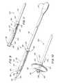
- FIG. 1is a side elevation view of a first preferred catheter assembly according to the invention
- FIG. 2is a perspective view of the first preferred catheter assembly in a high-profile state
- FIG. 3is a side elevation view of the first preferred catheter assembly in a low-profile state
- FIG. 4is a side elevation view of the first preferred catheter assembly in the high-profile state
- FIG. 5is a side elevation view of the first preferred catheter assembly in a released, low-profile state
- FIG. 6is a side elevation view of a second embodiment of a catheter assembly in a high-profile state
- FIG. 7is a side elevation view of a third embodiment of a catheter assembly in a low-profile state
- FIG. 8is a side elevation view of the third embodiment of a catheter assembly in a high-profile state
- FIG. 9is a perspective view of a fourth embodiment of a catheter assembly in a low-profile state
- FIG. 10is a perspective view of the fourth embodiment of a catheter assembly in a high-profile state
- FIG. 11is a perspective view of the fourth embodiment of a catheter assembly in a released, low-profile state
- FIG. 12is a schematic view of a catheter assembly of the present invention operatively disposed in a body conduit leading to a body cavity;
- FIG. 13is a schematic, operational view of the catheter assembly when an anchoring device is fully inserted into the body cavity;
- FIG. 14is schematic, operational view of the catheter assembly illustrating the self-deploying feature of the anchoring device upon slight withdrawal of the shaft;
- FIG. 15is a schematic, operational view of the catheter assembly illustrating the anchoring device automatically returning to a low-profile state upon release of a lock.
- FIG. 1A first preferred embodiment of a catheter assembly is illustrated in FIG. 1 and designated generally by the reference numeral 10 .
- This catheter assembly, or simply catheter 10has a self-deploying tip, or anchor assembly 12 , which can be advantageous in many catheter configurations.
- the catheter 10is adapted for urinary drainage where the anchor assembly 12 facilitates insertion of the catheter 10 , automatic deployment of the tip 12 , and simple removal of the catheter 10 .
- Other catheters which can benefit from the self-deployment properties of the anchor assembly 12include occlusion catheters, and generally any catheter in which the properties of minimal insertion force, maximum anchor force, and a simple release mechanism would be advantageous.
- the catheter assembly 10may be particularly adapted for drainage, it is to be expressly understood that the catheter assemblies according to the invention may be employed in any medical procedure in which a catheter is required to be inserted through a body conduit and anchored in a body cavity.
- the conduitscould be a naturally occurring body conduit, such as a urethra, or an artificially created conduit such as those created in nephrostomy. Therefore, the catheter assemblies according to the invention may be employed, for example, in surgical procedures, drainage procedures, infusion procedures, feeding procedures, nephrostomy, gastronomy and more.
- the catheter 10may include an elongate tubular body, or shaft, 14 having a shaft proximal end 16 and a shaft distal end 18 .
- a hub 21will commonly be fixed to the tubular body 14 at the shaft proximal end 16 .
- a stop 23may be provided to form an enlargement on the outer surface of the tubular body 14 . The position of the stop 23 is fixed at this stop location on the tubular body 14 .
- the walls of the tubular body 14can be perforated to form drainage ports, or apertures, 25 , which provide access from regions exterior of the catheter 10 into the lumen of the tubular body 14 .
- the stop 23forms part of the anchoring assembly 12 which provides the catheter 10 with its self-deploying tip configuration.
- This anchoring assembly 12may also include a bushing or slide 27 which is free to slide on the tubular body 14 , but only proximally of the stop 23 .
- the stop 23inhibits distal movement of the slide 27 along the tubular body 14 .
- the self-deployment mechanismalso includes a distal cap 30 which is movable relative to the body 14 between a first position in proximity to the shaft distal end 18 , and a second position wherein it is spaced distally of the distal end 18 .
- the cap 30could also function as a sliding bushing, such as the bushing 27 , and have its own stop, such as the stop 23 .
- the distal tip 18 of the tube 14would not be capped, as in the illustrated embodiment, but would extend through both bushings.
- the shaft distal end 18actually functions as a stop for the cap 30 as it inhibits proximal movement of the cap 30 along the tubular body 14 .
- An anchoring device 32has an anchor distal end 26 fixed to the cap 30 and an anchor proximal end 28 fixed to the slide 27 .
- the stop 23is thus disposed on the shaft 14 between the anchor distal end 26 and the anchor proximal end 28 of the anchoring device 32 .
- the anchoring device 32comprises a bulb.
- the bulb 32which can be formed of any biocompatible flexible material, can be provided with special characteristics facilitating drainage.
- the bulb 32is formed of a heat-settable material, such as polyester, and provided in the configuration of an open mesh so as to be liquid permeable.
- the apertures 25may be defined in the tube 14 such that they are located in an interior of the liquid permeable bulb 32 between the opposed anchor ends 26 , 28 .
- the anchoring device 32has a high-profile state and a low-profile state, each of which is dependent upon the relative positions of the anchor distal end 26 and the anchor proximal end 28 . Since the distal end 26 and proximal end 28 are coupled to the slide 27 and the cap 30 , respectively, the state of the anchoring device's profile is also determined by the relative positions of the slide 27 and cap 30 . Thus, when the slide 27 and cap 30 are in close proximity, as in a proximate relationship, the anchor proximal end 28 and anchor distal end 26 are closely spaced providing the anchoring device 32 with a high-profile, expanded configuration. When the slide 27 and cap 30 are widely spaced, as in a spaced relationship, the anchor proximal end 28 and anchor distal end 26 are more separated to provide the anchoring device 32 with a low-profile, narrow configuration.
- the relative movement of the slide 27 and cap 30 coupled to the anchor proximal end 28 and anchor distal end 26 of the anchoring device 32 , respectively,provides the self-deployment characteristics associated with the present invention.
- the only additional structure which may be required for this mechanismis a simple releasable lock 34 , such as-a suture, tube, string or other releasable tension member, which can be fixed to the cap 30 and threaded back through the lumen of the tubular body 14 .
- the string 34tensions the cap 30 in a proximal direction and holds it against its stop, such as the shaft distal end 18 of the tube 14 .
- the string 34can be manufactured so that its proximal end is maintained in a fixed relationship with the tube 14 .
- the proximal end of the string 34is fixed to the hub 21 .
- the string 34is under tension, but not attached to the tubular body 14 .
- the cap 30is maintained in its proximal position in a fixed relationship with the tube 14 . Since the cap 30 couples the releasable lock 34 to the anchor distal end 26 , the releasable lock 34 also tensions the anchor distal end 26 in a proximal direction, thereby holding the anchor distal end 26 in a distal end proximal position.
- the anchor proximal end 28 and corresponding slide 27 at the opposite end of the anchoring device 32is free to move along the tube 14 proximally of the stop 23 .
- These characteristicsgreatly facilitate insertion of the catheter 10 with the anchoring device 32 in a low-profile state, as illustrated in FIG. 3 . Insertion forces, which are exerted against the anchoring device 32 in a proximal direction, as shown in FIG. 12, tend to force the anchoring device 32 into a low-profile state, which is easily accommodated by movement of the anchor proximal end 28 and slide 27 proximally along the tube 14 .
- the cap 30With the cap 30 already in its proximal-most position against the stop or distal end 18 , it is not free to move in response to these insertion forces, thereby maintaining the anchor distal end 26 in the distal end proximal position. It will be appreciated that no external forces are required of the user in order to maintain the anchoring device 32 in the low-profile state during insertion.
- the anchoring device 32automatically self-deploys to this low-profile state with a simple, one-handed insertion force applied to the tubular body 14 without any further manual manipulation.
- the catheter 10In the case of a urinary drainage catheter, the catheter 10 is inserted through the urethra and past a bladder neck as it enters the bladder. Once the anchoring device 32 is inside the bladder, it is no longer constrained by the walls of the urethra to the low-profile state. By forming the bulb 32 of a heat-settable material, it can be heat-set to an enlarged profile, so that it automatically expands slightly within the bladder.
- the self-deployment characteristics of this inventionare particularly apparent at this point in the process, where it is intended that the distal end of the catheter 10 will be anchored within the bladder to facilitate the drainage of urine. This anchoring is automatically achieved by the slight withdrawal of the tube 14 proximally.
- this withdrawal forcebrings the slide 27 and the anchor proximal end in contact with the bladder neck, as shown in FIG. 14 .
- the withdrawal forcepushes distally against the slide 27 , causing it and the anchor proximal end to move distally to the stop 23 , as illustrated in FIG. 4 .
- the cap 30 and anchor distal end 26are not free to move distally in response to these withdrawal forces, but, instead, are held in this fixed, distal end proximal position. Accordingly, a slight withdrawal force brings the two ends 26 , 28 of the anchoring device 32 into close proximity and causes the anchoring device 32 to achieve its greatest radius in the high-profile state, illustrated in FIGS. 4 and 14.
- any proximal force tending to withdraw the catheter 10will only seek to maintain the enlarged high-profile state, which anchors the catheter 10 within the body cavity.
- the tube 14has merely been pushed forward slightly to facilitate insertion and then pulled backward slightly to lock the anchoring device 32 in its high-profile state. Deployment of the anchoring device 32 initially to the low-profile state and ultimately to the high-profile state has required no further action or force on the part of the user.
- the cap 30 and anchor distal end 26 in this embodimentare released from the distal end proximate position, so that they are free to move distally away from the slide 27 and anchor proximal end 28 . Then, when removal forces are applied to the tube 14 , they push distally on the anchoring device 32 forcing the cap 30 away from the slide 27 , thus spacing the anchor distal end 26 further from the anchor proximal end 28 . The anchor distal end 26 thus moves from the fixed, distal end proximal position to a released, distal end distal position.
- a button or slidecan be fixed to the suture 34 at the shaft proximal end 16 of the tube 14 . Movement of this slide 27 distally relative to the tube 14 will permit the string 34 and the attached cap 30 to also move distally.
- the tubular body 14is merely cut in two, thereby severing the suture 34 distally of its attachment to the tube 14 or hub 21 . If the suture 34 is attached to the hub 21 , the tube 14 need only be cut distally of the hub 21 . This will release the cap 30 from the shaft distal end 18 of the tube 14 in the manner previously discussed. However, the cap 30 is not free of the catheter 10 as it continues to be attached through the anchoring device 32 to the slide 27 which is constrained by the stop 23 .
- FIG. 5shows the cap 30 released from the shaft distal end 18 of the tube 14 .
- distally-directed withdrawal forcescause the slide 27 and anchor proximal end 28 to move against the stop 23 and further cause the cap 30 and anchor distal end 26 to move distally to an extent limited only by the length of the anchoring device 32 .
- the anchoring device 32With the maximum separation of the cap 30 and the slide 27 , resulting in the maximum separation of the anchor distal end 26 and anchor proximal end 28 , the anchoring device 32 is maintained in the low-profile state facilitating withdrawal of the catheter 10 , as illustrated in FIGS. 7 and 15.
- an anchoring devicecan be provided in the form of a Malecot-winged structure 32 b , including a plurality of leg pairs each having a living hinge 42 , as illustrated in FIG. 6 .
- the legs 40 of the Malecot structure 32 bare attached at one end to the associated living hinge and at the other end, 26 or 28 , to either the cap 30 or the slide 27 .
- the anchorcan also be formed as a spiral 32 c , as illustrated in FIGS. 7 and 8, with its anchor distal end 26 and anchor proximal end 28 fixed to the cap 30 and slide 27 , respectively.
- the spiral 36moves from its low-profile state, illustrated in FIG. 7, to its high-profile state, illustrated in FIG. 8 .
- the anchor device in any of the foregoing embodimentscan be formed of either plastic or metal materials. While plastic might be the preferred material for the woven mesh bulb, a metal material might be more appropriate for the spiral. Also, as previously noted, the string 34 can be interiorly attached to either the tube 14 or hub 21 . In this construction, the catheter 10 is entirely sealed between the shaft proximal end 16 and shaft distal end 18 . It remains sealed during insertion and throughout its operative use in the anchored state. The advantageous seal configuration is maintained until the tube 14 is cut and the catheter 10 is removed.
- the user of the catheter 10is merely required to provide a slight distal force to insert the catheter 10 , a slight proximal force to anchor the catheter 10 , and a cutting force to retract the catheter 10 .
- the tip 12automatically deploys to the low-profile insertion state, the high-profile anchor state, and the low-profile removal state. No additional structure is required, and no further steps of operation or manual manipulation are needed to use this catheter.
- FIGS. 9-11A further preferred embodiment of a urinary drainage catheter is illustrated in FIGS. 9-11 and designated by the reference numeral 100 .
- the catheter 100is representative generally of any medical instrument having an associated tube, or shaft, 112 which is adapted for insertion through a body conduit and for anchoring in a body cavity.
- the tube 112is a catheter body adapted for insertion through the urethra and into the bladder where the catheter 100 can be anchored to facilitate drainage of the bladder.
- the tube 112has a shaft proximal end 114 and a shaft distal end 116 , with an anchor assembly 118 having a high-profile state as illustrated in FIG. 10 and a low-profile state as illustrated in FIGS. 9 and 11.
- the anchoring assembly 118includes a stop, or block 121 fixed to the tube 112 generally at the position desired for the anchoring assembly 118 . Drainage is facilitated by holes 119 and 120 which extend into the tube 112 at the shaft distal end 116 .
- the anchoring assembly 118also includes an anchoring device 122 having an anchor proximal end 123 and an anchor distal end 125 .
- the anchoring assembly 118includes a proximal bushing 127 and a distal bushing 130 that further defined the anchor proximal end 123 and the anchor distal end 125 , respectively.
- the anchoring device 122preferably comprises a bulb.
- the proximal bushing 127is preferably mounted on the tube 112 proximally of the stop 121 , and is movable between a proximal position illustrated generally in FIGS. 10 and 11 by the reference numeral 134 , and a distal position illustrated generally in FIG. 9 by the reference numeral 132 . Accordingly, the anchor proximal end 123 is movable between a proximal end proximal position 132 , shown in FIG. 9, and a proximal end distal position 134 , shown in FIGS. 10 and 11.
- the distal bushing 130is disposed distally of the block 121 and is movable from a fixed, proximal position illustrated generally in FIGS. 10 and 11 by the reference numeral 136 , and a released, distal position illustrated generally in FIG. 14 by the reference numeral 138 .
- the anchor distal end 125is movable between a fixed, distal end proximal position 136 shown in FIGS. 9 and 10, and a released, distal end distal position 138 shown in FIG. 11 .
- a releasable locking mechanism 143is provided to maintain the distal bushing 130 in its proximal position 136 .
- this locking mechanism 143is provided in the form of a tension member such as a suture 143 which extends around the distal bushing 130 , through the holes 119 and 120 , and through the tube 112 where it is fixed at the shaft proximal end 114 .
- the tube 112 of the catheter 100is inserted into the body conduit, such as the urethra as shown in FIGS. 12 and 13.
- the distal bushing 130is locked in its proximate position by the suture, shown in FIG. 9 .
- Insertionis accomplished by resisting a proximally directed force 144 on the catheter 100 as it is pushed through the body conduit 180 .
- This proximally directed force 144tends to automatically move the bushings 127 and 130 to their proximal positions.
- the distal bushing 130cannot move proximally of the stop 121 , so further movement of the proximal bushing 127 proximally operates to separate the anchor ends 123 and 125 of the anchoring device 122 causing it to maintain a low-profile state.
- This low-profile statewhich occurs automatically, greatly facilitates insertion of the catheter 100 through the body conduit 180 , such as the urethra, and into the body cavity 182 , such as the bladder. In FIG. 13, this insertion continues preferably until the proximal bushing 127 passes into the body cavity.
- the catheter 100can be withdrawn slightly thereby creating a distally directed force 145 shown in FIG. 14 .
- This force 145is initially directed against the proximal bushing 127 causing it to move to its distal position 134 , shown in FIG. 10 .
- distal movement of the bushing 127causes the anchoring device 122 to move toward its high-profile state as illustrated in FIG. 14 . Further withdrawal of the catheter 100 , either accidentally or intentionally, is inhibited by the high profile of the anchoring device 22 .
- the catheter 100can remain for an indefinite period of time in body cavity 182 , such as the bladder.
- the locking mechanism 143When it is desirable to remove the catheter 100 from the body cavity, the locking mechanism 143 must be released or disengaged. In an embodiment including the suture 143 as shown in FIG. 9, this release can be facilitated by merely cutting the tube 112 of the catheter 100 at the proximal end 114 . This will disengage the suture 143 from the shaft 112 and thereby release the distal bushing 130 for movement to its distal position 138 as illustrated in FIGS. 11 and 15.
- this anchoring mechanism 118is optimized for a semi-permanent/implantable drainage catheter for several reasons. First, it maximizes the drainage internal diameter of the tube 112 because the anchoring mechanism 118 can rely on memory characteristics of the bulb 122 for its deployment. There is no need for a space-consuming inflation lumen or activation rod in the internal diameter of the tube 112 . All that is required to occupy the lumen is a relatively small tension member, such as the suture 143 .
- the tension memberis provided in the form of the suture 143 is advantageous not only because it is small but also because it is very flexible. This allows the catheter to more easily follow the contours of the body conduit without interference between the tension member and the natural geometry of the body.
- the activation and deactivation of the anchor mechanism 118is “automatic”. There is no need for a stylet or introducer sheath to facilitate either insertion or withdrawal of the catheter. There is no need for manual tensioning of the suture as in devices of the past. Furthermore, the deactivation feature requires only the severing of the tube 112 by any available means. This simplicity of activation provides a significant advantage particularly in the case of a urinary drainage catheter. No need exists for a sterile syringe, water or sterile mandrel as required by current urinary drainage catheters.
- the anchoring mechanism 118maximizes the strength of the anchoring device 122 because it allows for a “solid length” or “stacked” configuration to be achieved.
- the devicecould be easily designed with a fail-safe break strength in the tension member so that accidental removal attempts would undeploy the retention feature before its high profile in any way harmed the anatomy.
- This designwould also be well suited for drainage anywhere a catheter is introduced into natural cavities of the body such as the bladder, urethra, ureters, kidneys, lungs, etc., or into accidental or surgically-made cavities, for the purpose of evacuating liquid secretions which are not expelled in the normal manner.
- the devicepossesses a high degree of flexibility while maintaining itself permanently in position without extraneous means of attachment or fixation.
- the designdoes not have to be flexible.
- a version with a stiff tube or a stiff tension memberwould work if it were not necessary to follow a torturous body contour.
- a rigid preformed devicewould work as well as a straight version, for example if the device needed to have the general shape of an arc.
- the devicecould be made in a variety of sizes. For instance a relatively larger size for urine drainage or a relatively smaller size to anchor in the cystic ducts. Likewise the anchoring device 122 could be extremely porous for urine drainage or made with a water tight coating for a cholangeogram-type device.
- the anchoring assembly 118is well suited for retaining the position of laparoscopic trocars or instrumentation. Additionally, the retention feature could also be incorporated in Hand Assist Ports to anchor them in position. Furthermore, a version of the assembly 118 may be well suited as a “mechanical balloon” for clot or stone removal.
- the anchoring mechanism 118 as described abovepreferably includes the bulb 122
- this structureis merely representative of many other types of structures which might be advantageously incorporated in a particular embodiment.
- the anchoring device 122has a pair of ends, the proximity of which determine whether the structure has a high profile or a low profile.
- This bulb 122might be replaced by a spiral structure or a Malecot-winged structure.
- the bulb 122 and its equivalentsare not necessarily required to be coaxial with the shaft 112 in order to accomplish its anchoring function.
- the locking mechanism 143is described to include a suture.
- any structure removably present in the path of the distal bushing or capcould perform this function.
- the retaining objectcould be removed from the path of the bushing 130 by a rod or even hydraulics applied through the tube 112 .
Landscapes
- Health & Medical Sciences (AREA)
- Life Sciences & Earth Sciences (AREA)
- Heart & Thoracic Surgery (AREA)
- Biomedical Technology (AREA)
- Engineering & Computer Science (AREA)
- Anesthesiology (AREA)
- Pulmonology (AREA)
- Biophysics (AREA)
- Hematology (AREA)
- Animal Behavior & Ethology (AREA)
- General Health & Medical Sciences (AREA)
- Public Health (AREA)
- Veterinary Medicine (AREA)
- Child & Adolescent Psychology (AREA)
- External Artificial Organs (AREA)
Abstract
Description
Claims (28)
Priority Applications (2)
| Application Number | Priority Date | Filing Date | Title |
|---|---|---|---|
| US09/870,255US6589208B2 (en) | 2000-06-20 | 2001-05-30 | Self-deploying catheter assembly |
| US10/403,758US6837871B2 (en) | 2000-06-20 | 2003-03-31 | Self-deploying catheter assembly |
Applications Claiming Priority (3)
| Application Number | Priority Date | Filing Date | Title |
|---|---|---|---|
| US21291200P | 2000-06-20 | 2000-06-20 | |
| US26079401P | 2001-01-09 | 2001-01-09 | |
| US09/870,255US6589208B2 (en) | 2000-06-20 | 2001-05-30 | Self-deploying catheter assembly |
Related Child Applications (1)
| Application Number | Title | Priority Date | Filing Date |
|---|---|---|---|
| US10/403,758Continuation-In-PartUS6837871B2 (en) | 2000-06-20 | 2003-03-31 | Self-deploying catheter assembly |
Publications (2)
| Publication Number | Publication Date |
|---|---|
| US20010056273A1 US20010056273A1 (en) | 2001-12-27 |
| US6589208B2true US6589208B2 (en) | 2003-07-08 |
Family
ID=27395797
Family Applications (1)
| Application Number | Title | Priority Date | Filing Date |
|---|---|---|---|
| US09/870,255Expired - LifetimeUS6589208B2 (en) | 2000-06-20 | 2001-05-30 | Self-deploying catheter assembly |
Country Status (1)
| Country | Link |
|---|---|
| US (1) | US6589208B2 (en) |
Cited By (124)
| Publication number | Priority date | Publication date | Assignee | Title |
|---|---|---|---|---|
| US20030083538A1 (en)* | 2001-11-01 | 2003-05-01 | Cardiac Dimensions, Inc. | Focused compression mitral valve device and method |
| US20030171776A1 (en)* | 2002-03-06 | 2003-09-11 | Cardiac Dimensions, Inc. | Transvenous staples, assembly and method for mitral valve repair |
| US20030212453A1 (en)* | 2002-05-08 | 2003-11-13 | Cardiac Dimensions, Inc. | Body lumen device anchor, device and assembly |
| US20030225454A1 (en)* | 2002-01-30 | 2003-12-04 | Cardiac Dimensions, Inc. | Device and method for modifying the shape of a body organ |
| US20030236569A1 (en)* | 2002-01-30 | 2003-12-25 | Cardiac Dimensions, Inc. | Device and method for modifying the shape of a body organ |
| US20040010305A1 (en)* | 2001-12-05 | 2004-01-15 | Cardiac Dimensions, Inc. | Device and method for modifying the shape of a body organ |
| US20040111095A1 (en)* | 2002-12-05 | 2004-06-10 | Cardiac Dimensions, Inc. | Medical device delivery system |
| US20040122456A1 (en)* | 2002-12-11 | 2004-06-24 | Saadat Vahid C. | Methods and apparatus for gastric reduction |
| US20040153147A1 (en)* | 2003-02-03 | 2004-08-05 | Cardiac Dimensions, Inc. | Mitral valve device using conditioned shape memory alloy |
| US20040153052A1 (en)* | 2001-05-14 | 2004-08-05 | Cardiac Dimensions, Inc. | Mitral valve therapy assembly and method |
| US20040158321A1 (en)* | 2003-02-12 | 2004-08-12 | Cardiac Dimensions, Inc. | Method of implanting a mitral valve therapy device |
| US6793673B2 (en) | 2002-12-26 | 2004-09-21 | Cardiac Dimensions, Inc. | System and method to effect mitral valve annulus of a heart |
| US6797001B2 (en) | 2002-03-11 | 2004-09-28 | Cardiac Dimensions, Inc. | Device, assembly and method for mitral valve repair |
| US20040193143A1 (en)* | 2002-03-20 | 2004-09-30 | Manfred Sauer | Catheter for drainage of the bladder |
| US6800090B2 (en) | 2001-05-14 | 2004-10-05 | Cardiac Dimensions, Inc. | Mitral valve therapy device, system and method |
| US20040215230A1 (en)* | 2003-04-28 | 2004-10-28 | Frazier Andrew G. C. | Left atrial appendage occlusion device with active expansion |
| US20050004667A1 (en)* | 2003-06-05 | 2005-01-06 | Cardiac Dimensions, Inc. A Delaware Corporation | Device, system and method to affect the mitral valve annulus of a heart |
| US20050096666A1 (en)* | 2002-12-05 | 2005-05-05 | Gordon Lucas S. | Percutaneous mitral valve annuloplasty delivery system |
| US20050119685A1 (en)* | 2003-10-17 | 2005-06-02 | Smith Robert C. | Expandible surgical access device |
| US6908478B2 (en) | 2001-12-05 | 2005-06-21 | Cardiac Dimensions, Inc. | Anchor and pull mitral valve device and method |
| US20050137685A1 (en)* | 2003-12-19 | 2005-06-23 | Cardiac Dimensions, Inc., A Washington Corporation | Reduced length tissue shaping device |
| US20050137449A1 (en)* | 2003-12-19 | 2005-06-23 | Cardiac Dimensions, Inc. | Tissue shaping device with self-expanding anchors |
| US20050209690A1 (en)* | 2002-01-30 | 2005-09-22 | Mathis Mark L | Body lumen shaping device with cardiac leads |
| US6976995B2 (en) | 2002-01-30 | 2005-12-20 | Cardiac Dimensions, Inc. | Fixed length anchor and pull mitral valve device and method |
| US20060079845A1 (en)* | 2004-10-08 | 2006-04-13 | Eben Howard And Pamela A. Howard | Movable inflatable anchor for medical devices |
| US20060155311A1 (en)* | 2001-05-17 | 2006-07-13 | Kiyoshi Hashiba | Intragastric device for treating obesity |
| US20060167544A1 (en)* | 2005-01-20 | 2006-07-27 | Cardiac Dimensions, Inc. | Tissue Shaping Device |
| US20060184242A1 (en)* | 2003-10-20 | 2006-08-17 | Samuel Lichtenstein | Method and apparatus for percutaneous reduction of anterior-posterior diameter of mitral valve |
| US20060229553A1 (en)* | 2005-04-12 | 2006-10-12 | Vance Products Incorporated, D/B/A Cook Urological Incorporated | Catheter with superelastic retention device |
| US20060241735A1 (en)* | 2005-04-26 | 2006-10-26 | Cardiac Pacemakers, Inc. | Self-deploying vascular occlusion device |
| US20070016134A1 (en)* | 2003-04-28 | 2007-01-18 | Yutaka Suzuki | Catheter kit for burrow |
| US20070088258A1 (en)* | 2005-10-13 | 2007-04-19 | Tyco Healthcare Group, Lp | Trocar anchor |
| US20080058728A1 (en)* | 2006-08-02 | 2008-03-06 | Soltz Michael A | Stabilization assist device for trocar |
| US20080087608A1 (en)* | 2006-10-10 | 2008-04-17 | Multiphase Systems Integration | Compact multiphase inline bulk water separation method and system for hydrocarbon production |
| US20080228198A1 (en)* | 2007-03-13 | 2008-09-18 | Mitralign, Inc. | Suture cutter and method of cutting suture |
| US20080228266A1 (en)* | 2007-03-13 | 2008-09-18 | Mitralign, Inc. | Plication assistance devices and methods |
| US7431726B2 (en) | 2003-12-23 | 2008-10-07 | Mitralign, Inc. | Tissue fastening systems and methods utilizing magnetic guidance |
| US7503932B2 (en) | 2006-04-11 | 2009-03-17 | Cardiac Dimensions, Inc. | Mitral valve annuloplasty device with vena cava anchor |
| US20090105691A1 (en)* | 2007-10-17 | 2009-04-23 | Tyco Healthcare Group Lp | Access port using shape memory anchor |
| WO2007009021A3 (en)* | 2005-07-11 | 2009-05-28 | Usgi Medical Inc | Compressible tissue anchor assemblies |
| US7635387B2 (en) | 2001-11-01 | 2009-12-22 | Cardiac Dimensions, Inc. | Adjustable height focal tissue deflector |
| US20100010448A1 (en)* | 2008-07-09 | 2010-01-14 | Cook Incorporated | Anchor assembly |
| US20100070028A1 (en)* | 2008-09-12 | 2010-03-18 | Mitralign, Inc. | Tissue plication device and method for its use |
| US7736379B2 (en) | 2004-06-09 | 2010-06-15 | Usgi Medical, Inc. | Compressible tissue anchor assemblies |
| US7736378B2 (en) | 2004-05-07 | 2010-06-15 | Usgi Medical, Inc. | Apparatus and methods for positioning and securing anchors |
| US7744613B2 (en) | 1999-06-25 | 2010-06-29 | Usgi Medical, Inc. | Apparatus and methods for forming and securing gastrointestinal tissue folds |
| US7749249B2 (en) | 2006-02-21 | 2010-07-06 | Kardium Inc. | Method and device for closing holes in tissue |
| US20100198257A1 (en)* | 2006-09-06 | 2010-08-05 | Joshua Stopek | Bioactive Substance in a Barbed Suture |
| US20100204730A1 (en)* | 2008-10-09 | 2010-08-12 | Nicholas Maiorino | Knotted Suture End Effector |
| US20100204729A1 (en)* | 2008-09-11 | 2010-08-12 | Ahmad Robert Hadba | Tapered Looped Suture |
| US20100211097A1 (en)* | 2008-02-20 | 2010-08-19 | Ahmad Robert Hadba | Compound Barb Medical Device and Method |
| US20100211098A1 (en)* | 2008-02-20 | 2010-08-19 | Ahmad Robert Hadba | Compound Barb Medical Device and Method |
| US7794496B2 (en) | 2003-12-19 | 2010-09-14 | Cardiac Dimensions, Inc. | Tissue shaping device with integral connector and crimp |
| US7828841B2 (en) | 2002-05-08 | 2010-11-09 | Cardiac Dimensions, Inc. | Device and method for modifying the shape of a body organ |
| US7837610B2 (en) | 2006-08-02 | 2010-11-23 | Kardium Inc. | System for improving diastolic dysfunction |
| US7887582B2 (en) | 2003-06-05 | 2011-02-15 | Cardiac Dimensions, Inc. | Device and method for modifying the shape of a body organ |
| US7918845B2 (en) | 2003-01-15 | 2011-04-05 | Usgi Medical, Inc. | Endoluminal tool deployment system |
| US20110106113A1 (en)* | 2007-07-13 | 2011-05-05 | The Brigham And Women's Hospital, Inc. | System and method for hernia mesh fixation |
| US7942898B2 (en) | 2002-12-11 | 2011-05-17 | Usgi Medical, Inc. | Delivery systems and methods for gastric reduction |
| US7942884B2 (en) | 2002-12-11 | 2011-05-17 | Usgi Medical, Inc. | Methods for reduction of a gastric lumen |
| US8006594B2 (en) | 2008-08-11 | 2011-08-30 | Cardiac Dimensions, Inc. | Catheter cutting tool |
| US8150499B2 (en) | 2006-05-19 | 2012-04-03 | Kardium Inc. | Automatic atherectomy system |
| US8206291B2 (en) | 2009-03-27 | 2012-06-26 | Tyco Healthcare Group Lp | Portal device |
| US8206417B2 (en) | 2004-06-09 | 2012-06-26 | Usgi Medical Inc. | Apparatus and methods for optimizing anchoring force |
| US8216260B2 (en) | 2002-12-11 | 2012-07-10 | Usgi Medical, Inc. | Apparatus and methods for forming and securing gastrointestinal tissue folds |
| US8257394B2 (en) | 2004-05-07 | 2012-09-04 | Usgi Medical, Inc. | Apparatus and methods for positioning and securing anchors |
| US8277418B2 (en) | 2009-12-23 | 2012-10-02 | Alcon Research, Ltd. | Ophthalmic valved trocar cannula |
| US8298291B2 (en) | 2005-05-26 | 2012-10-30 | Usgi Medical, Inc. | Methods and apparatus for securing and deploying tissue anchors |
| US8343106B2 (en) | 2009-12-23 | 2013-01-01 | Alcon Research, Ltd. | Ophthalmic valved trocar vent |
| US8444657B2 (en) | 2004-05-07 | 2013-05-21 | Usgi Medical, Inc. | Apparatus and methods for rapid deployment of tissue anchors |
| US8449605B2 (en) | 2006-06-28 | 2013-05-28 | Kardium Inc. | Method for anchoring a mitral valve |
| US8460371B2 (en) | 2002-10-21 | 2013-06-11 | Mitralign, Inc. | Method and apparatus for performing catheter-based annuloplasty using local plications |
| US8489172B2 (en) | 2008-01-25 | 2013-07-16 | Kardium Inc. | Liposuction system |
| US20140303444A1 (en)* | 2008-06-25 | 2014-10-09 | Covidien Lp | Button port |
| US8864822B2 (en) | 2003-12-23 | 2014-10-21 | Mitralign, Inc. | Devices and methods for introducing elements into tissue |
| US8870916B2 (en) | 2006-07-07 | 2014-10-28 | USGI Medical, Inc | Low profile tissue anchors, tissue anchor systems, and methods for their delivery and use |
| US8906011B2 (en) | 2007-11-16 | 2014-12-09 | Kardium Inc. | Medical device for use in bodily lumens, for example an atrium |
| US8920411B2 (en) | 2006-06-28 | 2014-12-30 | Kardium Inc. | Apparatus and method for intra-cardiac mapping and ablation |
| US8926634B2 (en) | 2004-05-07 | 2015-01-06 | Usgi Medical, Inc. | Apparatus and methods for manipulating and securing tissue |
| US8940002B2 (en) | 2010-09-30 | 2015-01-27 | Kardium Inc. | Tissue anchor system |
| US8951285B2 (en) | 2005-07-05 | 2015-02-10 | Mitralign, Inc. | Tissue anchor, anchoring system and methods of using the same |
| USD724201S1 (en)* | 2013-04-08 | 2015-03-10 | Cardio3 Biosciences S.A. | Part of injection catheter handle |
| US8979923B2 (en) | 2002-10-21 | 2015-03-17 | Mitralign, Inc. | Tissue fastening systems and methods utilizing magnetic guidance |
| US9011423B2 (en) | 2012-05-21 | 2015-04-21 | Kardium, Inc. | Systems and methods for selecting, activating, or selecting and activating transducers |
| US9050066B2 (en) | 2010-06-07 | 2015-06-09 | Kardium Inc. | Closing openings in anatomical tissue |
| US9072511B2 (en) | 2011-03-25 | 2015-07-07 | Kardium Inc. | Medical kit for constricting tissue or a bodily orifice, for example, a mitral valve |
| US20150209239A1 (en)* | 2012-08-17 | 2015-07-30 | Chris Salvino | Nasogastric tube |
| US9119633B2 (en) | 2006-06-28 | 2015-09-01 | Kardium Inc. | Apparatus and method for intra-cardiac mapping and ablation |
| US9198592B2 (en) | 2012-05-21 | 2015-12-01 | Kardium Inc. | Systems and methods for activating transducers |
| US9204964B2 (en) | 2009-10-01 | 2015-12-08 | Kardium Inc. | Medical device, kit and method for constricting tissue or a bodily orifice, for example, a mitral valve |
| US9237897B2 (en) | 2005-09-12 | 2016-01-19 | Bridgepoint Medical, Inc. | Endovascular devices and methods |
| US20160045220A1 (en)* | 2014-08-15 | 2016-02-18 | Applied Medical Resources Corporation | Natural orifice surgery system |
| US9265514B2 (en) | 2012-04-17 | 2016-02-23 | Miteas Ltd. | Manipulator for grasping tissue |
| US9358112B2 (en) | 2001-04-24 | 2016-06-07 | Mitralign, Inc. | Method and apparatus for catheter-based annuloplasty using local plications |
| USD762847S1 (en) | 2013-04-08 | 2016-08-02 | Celyad S.A. | Part of injection catheter handle |
| US9452016B2 (en) | 2011-01-21 | 2016-09-27 | Kardium Inc. | Catheter system |
| US9480525B2 (en) | 2011-01-21 | 2016-11-01 | Kardium, Inc. | High-density electrode-based medical device system |
| US9492227B2 (en) | 2011-01-21 | 2016-11-15 | Kardium Inc. | Enhanced medical device for use in bodily cavities, for example an atrium |
| US9526616B2 (en) | 2003-12-19 | 2016-12-27 | Cardiac Dimensions Pty. Ltd. | Mitral valve annuloplasty device with twisted anchor |
| USD776805S1 (en) | 2013-04-08 | 2017-01-17 | Celyad S.A. | Injection catheter handle |
| USD777926S1 (en) | 2012-01-20 | 2017-01-31 | Kardium Inc. | Intra-cardiac procedure device |
| USD777925S1 (en) | 2012-01-20 | 2017-01-31 | Kardium Inc. | Intra-cardiac procedure device |
| US9585651B2 (en) | 2005-05-26 | 2017-03-07 | Usgi Medical, Inc. | Methods and apparatus for securing and deploying tissue anchors |
| USD791978S1 (en)* | 2015-08-27 | 2017-07-11 | Vimecon Gmbh | Catheter handle |
| US9744038B2 (en) | 2008-05-13 | 2017-08-29 | Kardium Inc. | Medical device for constricting tissue or a bodily orifice, for example a mitral valve |
| US9950138B2 (en) | 2012-07-23 | 2018-04-24 | University Of Utah Research Foundation | Indwelling urinary catheter |
| US10028783B2 (en) | 2006-06-28 | 2018-07-24 | Kardium Inc. | Apparatus and method for intra-cardiac mapping and ablation |
| WO2018191193A1 (en) | 2017-04-10 | 2018-10-18 | Faltmed, Llc. | Catheter for guiding body fluid |
| US10314471B2 (en) | 2013-05-21 | 2019-06-11 | Smart Medical Systems Ltd. | Endoscope reprocessing method |
| US10368936B2 (en) | 2014-11-17 | 2019-08-06 | Kardium Inc. | Systems and methods for selecting, activating, or selecting and activating transducers |
| US10390953B2 (en) | 2017-03-08 | 2019-08-27 | Cardiac Dimensions Pty. Ltd. | Methods and devices for reducing paravalvular leakage |
| US10398295B2 (en) | 2014-12-22 | 2019-09-03 | Smart Medical Systems Ltd. | Balloon endoscope reprocessing system and method |
| US10456564B2 (en) | 2011-03-07 | 2019-10-29 | Smart Medical Systems Ltd. | Balloon-equipped endoscopic devices and methods thereof |
| US10610086B2 (en) | 2010-03-09 | 2020-04-07 | Smart Medical Systems Ltd. | Balloon endoscope and methods of manufacture and use thereof |
| US10722184B2 (en) | 2014-11-17 | 2020-07-28 | Kardium Inc. | Systems and methods for selecting, activating, or selecting and activating transducers |
| US10827977B2 (en) | 2012-05-21 | 2020-11-10 | Kardium Inc. | Systems and methods for activating transducers |
| US10835107B2 (en) | 2015-04-03 | 2020-11-17 | Smart Medical Systems Ltd. | Endoscope electro-pneumatic adaptor |
| US10918373B2 (en) | 2013-08-31 | 2021-02-16 | Edwards Lifesciences Corporation | Devices and methods for locating and implanting tissue anchors at mitral valve commissure |
| US11259867B2 (en) | 2011-01-21 | 2022-03-01 | Kardium Inc. | High-density electrode-based medical device system |
| US11285005B2 (en) | 2006-07-17 | 2022-03-29 | Cardiac Dimensions Pty. Ltd. | Mitral valve annuloplasty device with twisted anchor |
| US11311380B2 (en) | 2003-05-02 | 2022-04-26 | Cardiac Dimensions Pty. Ltd. | Device and method for modifying the shape of a body organ |
| US11389232B2 (en) | 2006-06-28 | 2022-07-19 | Kardium Inc. | Apparatus and method for intra-cardiac mapping and ablation |
| US11596771B2 (en) | 2020-12-14 | 2023-03-07 | Cardiac Dimensions Pty. Ltd. | Modular pre-loaded medical implants and delivery systems |
| US11660190B2 (en) | 2007-03-13 | 2023-05-30 | Edwards Lifesciences Corporation | Tissue anchors, systems and methods, and devices |
Families Citing this family (37)
| Publication number | Priority date | Publication date | Assignee | Title |
|---|---|---|---|---|
| US6837871B2 (en)* | 2000-06-20 | 2005-01-04 | Applied Medical Resources | Self-deploying catheter assembly |
| US20030135269A1 (en)* | 2002-01-16 | 2003-07-17 | Swanstrom Lee L. | Laparoscopic-assisted endovascular/endoluminal graft placement |
| US20040236366A1 (en)* | 2002-05-16 | 2004-11-25 | Kennedy Kenneth C. | Non-buckling balloon catheter |
| JP4527058B2 (en)* | 2003-01-30 | 2010-08-18 | 住友ベークライト株式会社 | Puncture balloon |
| GB0304439D0 (en)* | 2003-02-27 | 2003-04-02 | Imp College Innovations Ltd | A device |
| US6942641B2 (en)* | 2003-05-30 | 2005-09-13 | J. Michael Seddon | Catheter |
| US7766899B2 (en)* | 2003-09-17 | 2010-08-03 | Prostalund Operations Ab | Partial-length, indwelling prostatic catheter using coiled inflation tube as an anchor and methods of draining urine and flushing clots |
| US11020141B2 (en) | 2005-09-12 | 2021-06-01 | Bridgepoint Medical, Inc. | Endovascular devices and methods |
| US7918870B2 (en) | 2005-09-12 | 2011-04-05 | Bridgepoint Medical, Inc. | Endovascular devices and methods |
| US8083727B2 (en) | 2005-09-12 | 2011-12-27 | Bridgepoint Medical, Inc. | Endovascular devices and methods for exploiting intramural space |
| WO2007033052A2 (en) | 2005-09-12 | 2007-03-22 | Bridgepoint Medical, Inc. | Endovascular devices and methods for exploiting intramural space |
| GB0519259D0 (en)* | 2005-09-21 | 2005-10-26 | Imp College Innovations Ltd | A device |
| US11298511B2 (en) | 2006-11-21 | 2022-04-12 | Bridgepoint Medical, Inc. | Endovascular devices and methods for exploiting intramural space |
| US10888354B2 (en)* | 2006-11-21 | 2021-01-12 | Bridgepoint Medical, Inc. | Endovascular devices and methods for exploiting intramural space |
| US9060802B2 (en) | 2006-11-21 | 2015-06-23 | Bridgepoint Medical, Inc. | Endovascular devices and methods for exploiting intramural space |
| US8025636B2 (en)* | 2007-05-02 | 2011-09-27 | Boston Scientific Scimed, Inc. | Balloon catheters |
| US8632556B2 (en) | 2007-10-22 | 2014-01-21 | Bridgepoint Medical, Inc. | Methods and devices for crossing chronic total occlusions |
| US11992238B2 (en) | 2008-02-05 | 2024-05-28 | Boston Scientific Scimed, Inc. | Endovascular device with a tissue piercing distal probe and associated methods |
| US8337425B2 (en) | 2008-02-05 | 2012-12-25 | Bridgepoint Medical, Inc. | Endovascular device with a tissue piercing distal probe and associated methods |
| WO2009134346A2 (en) | 2008-04-28 | 2009-11-05 | David Bryan Robinson | Methods and apparatus for crossing occlusions in blood vessels |
| US8882678B2 (en) | 2009-03-13 | 2014-11-11 | Atrium Medical Corporation | Pleural drainage system and method of use |
| JP5726029B2 (en) | 2011-09-14 | 2015-05-27 | 日本コヴィディエン株式会社 | Fistula catheter |
| US20130085468A1 (en)* | 2011-10-03 | 2013-04-04 | Yuri Buydenok | Catheter with body wall separator |
| CA2852898A1 (en)* | 2011-10-21 | 2013-04-25 | Boston Scientific Scimed, Inc. | Locking catheter hub |
| CN105073173B (en)* | 2013-01-18 | 2017-05-10 | 斯坦福国际研究院 | anchored nerve block catheter |
| US10918827B2 (en)* | 2015-07-20 | 2021-02-16 | Strataca Systems Limited | Catheter device and method for inducing negative pressure in a patient's bladder |
| US11040172B2 (en) | 2015-07-20 | 2021-06-22 | Strataca Systems Limited | Ureteral and bladder catheters and methods of inducing negative pressure to increase renal perfusion |
| HUE049050T2 (en) | 2015-07-20 | 2020-08-28 | Strataca Systems Ltd | Ureteral and bladder catheters |
| US12064567B2 (en) | 2015-07-20 | 2024-08-20 | Roivios Limited | Percutaneous urinary catheter |
| US10493232B2 (en) | 2015-07-20 | 2019-12-03 | Strataca Systems Limited | Ureteral catheters, bladder catheters, systems, kits and methods for inducing negative pressure to increase renal function |
| US10926062B2 (en) | 2015-07-20 | 2021-02-23 | Strataca Systems Limited | Ureteral and bladder catheters and methods of inducing negative pressure to increase renal perfusion |
| WO2018200643A1 (en)* | 2017-04-25 | 2018-11-01 | Strataca Systems Limited | Catheter and method for inducing negative pressure in a patient's bladder |
| JP2020531159A (en) | 2017-08-25 | 2020-11-05 | ストラタカ システムズ リミテッド | Indwelling pump to facilitate removal of urine from the urinary tract |
| EP3586900A1 (en) | 2018-06-28 | 2020-01-01 | Medinice S.A. | Cannula for minimally invasive surgical tricuspid valve repair |
| US11950841B2 (en) | 2020-09-22 | 2024-04-09 | Biosense Webster (Israel) Ltd. | Basket catheter having insulated ablation electrodes and diagnostic electrodes |
| US11950840B2 (en)* | 2020-09-22 | 2024-04-09 | Biosense Webster (Israel) Ltd. | Basket catheter having insulated ablation electrodes |
| CN113967305B (en)* | 2021-12-22 | 2022-06-03 | 德宝恒生科技服务有限公司 | Urination tube |
Citations (17)
| Publication number | Priority date | Publication date | Assignee | Title |
|---|---|---|---|---|
| US5250025A (en)* | 1990-08-15 | 1993-10-05 | Intramed Laboratories | Percutaneous access catheter and method of use |
| US5499994A (en)* | 1993-07-30 | 1996-03-19 | American Medical Systems, Inc. | Dilation device for the urethra |
| US5626614A (en)* | 1995-12-22 | 1997-05-06 | Applied Medical Resources Corporation | T-anchor suturing device and method for using same |
| US5728133A (en)* | 1996-07-09 | 1998-03-17 | Cardiologics, L.L.C. | Anchoring device and method for sealing percutaneous punctures in vessels |
| US5795325A (en)* | 1991-07-16 | 1998-08-18 | Heartport, Inc. | Methods and apparatus for anchoring an occluding member |
| US5836913A (en)* | 1997-05-02 | 1998-11-17 | Innerdyne, Inc. | Device and method for accessing a body cavity |
| US5868762A (en)* | 1997-09-25 | 1999-02-09 | Sub-Q, Inc. | Percutaneous hemostatic suturing device and method |
| US5925060A (en)* | 1998-03-13 | 1999-07-20 | B. Braun Celsa | Covered self-expanding vascular occlusion device |
| US5935107A (en)* | 1996-10-07 | 1999-08-10 | Applied Medical Resources Corporation | Apparatus and method for surgically accessing a body cavity |
| US5993473A (en)* | 1997-11-19 | 1999-11-30 | Chan; Yung C. | Expandable body device for the gastric cavity and method |
| US6014589A (en)* | 1997-11-12 | 2000-01-11 | Vnus Medical Technologies, Inc. | Catheter having expandable electrodes and adjustable stent |
| US6048357A (en)* | 1998-07-09 | 2000-04-11 | X-Site, L.L.C. | Anchoring device and method for sealing punctures in vessels |
| US6280474B1 (en)* | 1997-01-09 | 2001-08-28 | Neucoll, Inc. | Devices for tissue repair and methods for preparation and use thereof |
| US6290674B1 (en)* | 1999-09-20 | 2001-09-18 | Appriva Medical, Inc. | Method and apparatus for closing intracardiac septal defects |
| US6312448B1 (en)* | 1996-11-15 | 2001-11-06 | Peter M. Bonutti | Apparatus and method for use in positioning an anchor |
| US6315789B1 (en)* | 1999-02-08 | 2001-11-13 | Andrew H. Cragg | Medical device anchoring system and method |
| US6368338B1 (en)* | 1999-03-05 | 2002-04-09 | Board Of Regents, The University Of Texas | Occlusion method and apparatus |
- 2001
- 2001-05-30USUS09/870,255patent/US6589208B2/ennot_activeExpired - Lifetime
Patent Citations (18)
| Publication number | Priority date | Publication date | Assignee | Title |
|---|---|---|---|---|
| US5250025A (en)* | 1990-08-15 | 1993-10-05 | Intramed Laboratories | Percutaneous access catheter and method of use |
| US5795325A (en)* | 1991-07-16 | 1998-08-18 | Heartport, Inc. | Methods and apparatus for anchoring an occluding member |
| US5499994A (en)* | 1993-07-30 | 1996-03-19 | American Medical Systems, Inc. | Dilation device for the urethra |
| US5626614A (en)* | 1995-12-22 | 1997-05-06 | Applied Medical Resources Corporation | T-anchor suturing device and method for using same |
| US5928266A (en)* | 1996-07-09 | 1999-07-27 | X-Site, L.L.C. | Anchoring device and method for sealing percutaneous punctures in vessels |
| US5728133A (en)* | 1996-07-09 | 1998-03-17 | Cardiologics, L.L.C. | Anchoring device and method for sealing percutaneous punctures in vessels |
| US5935107A (en)* | 1996-10-07 | 1999-08-10 | Applied Medical Resources Corporation | Apparatus and method for surgically accessing a body cavity |
| US6312448B1 (en)* | 1996-11-15 | 2001-11-06 | Peter M. Bonutti | Apparatus and method for use in positioning an anchor |
| US6280474B1 (en)* | 1997-01-09 | 2001-08-28 | Neucoll, Inc. | Devices for tissue repair and methods for preparation and use thereof |
| US5836913A (en)* | 1997-05-02 | 1998-11-17 | Innerdyne, Inc. | Device and method for accessing a body cavity |
| US5868762A (en)* | 1997-09-25 | 1999-02-09 | Sub-Q, Inc. | Percutaneous hemostatic suturing device and method |
| US6014589A (en)* | 1997-11-12 | 2000-01-11 | Vnus Medical Technologies, Inc. | Catheter having expandable electrodes and adjustable stent |
| US5993473A (en)* | 1997-11-19 | 1999-11-30 | Chan; Yung C. | Expandable body device for the gastric cavity and method |
| US5925060A (en)* | 1998-03-13 | 1999-07-20 | B. Braun Celsa | Covered self-expanding vascular occlusion device |
| US6048357A (en)* | 1998-07-09 | 2000-04-11 | X-Site, L.L.C. | Anchoring device and method for sealing punctures in vessels |
| US6315789B1 (en)* | 1999-02-08 | 2001-11-13 | Andrew H. Cragg | Medical device anchoring system and method |
| US6368338B1 (en)* | 1999-03-05 | 2002-04-09 | Board Of Regents, The University Of Texas | Occlusion method and apparatus |
| US6290674B1 (en)* | 1999-09-20 | 2001-09-18 | Appriva Medical, Inc. | Method and apparatus for closing intracardiac septal defects |
Cited By (326)
| Publication number | Priority date | Publication date | Assignee | Title |
|---|---|---|---|---|
| US7955340B2 (en) | 1999-06-25 | 2011-06-07 | Usgi Medical, Inc. | Apparatus and methods for forming and securing gastrointestinal tissue folds |
| US7744613B2 (en) | 1999-06-25 | 2010-06-29 | Usgi Medical, Inc. | Apparatus and methods for forming and securing gastrointestinal tissue folds |
| US9358112B2 (en) | 2001-04-24 | 2016-06-07 | Mitralign, Inc. | Method and apparatus for catheter-based annuloplasty using local plications |
| US20050261704A1 (en)* | 2001-05-14 | 2005-11-24 | Mathis Mark L | Mitral valve therapy assembly and method |
| US6800090B2 (en) | 2001-05-14 | 2004-10-05 | Cardiac Dimensions, Inc. | Mitral valve therapy device, system and method |
| US6966926B2 (en) | 2001-05-14 | 2005-11-22 | Cardiac Dimensions, Inc. | Mitral valve therapy assembly and method |
| US7828843B2 (en) | 2001-05-14 | 2010-11-09 | Cardiac Dimensions, Inc. | Mitral valve therapy device, system and method |
| US20050038507A1 (en)* | 2001-05-14 | 2005-02-17 | Alferness Clifton A. | Mitral valve therapy device, system and method |
| US20050033419A1 (en)* | 2001-05-14 | 2005-02-10 | Alferness Clifton A. | Mitral valve therapy device, system and method |
| US20040153052A1 (en)* | 2001-05-14 | 2004-08-05 | Cardiac Dimensions, Inc. | Mitral valve therapy assembly and method |
| US7270676B2 (en) | 2001-05-14 | 2007-09-18 | Cardiac Dimensions, Inc. | Mitral valve therapy device, system and method |
| US20050027351A1 (en)* | 2001-05-14 | 2005-02-03 | Cardiac Dimensions, Inc. A Washington Corporation | Mitral valve regurgitation treatment device and method |
| US20060155311A1 (en)* | 2001-05-17 | 2006-07-13 | Kiyoshi Hashiba | Intragastric device for treating obesity |
| US7635387B2 (en) | 2001-11-01 | 2009-12-22 | Cardiac Dimensions, Inc. | Adjustable height focal tissue deflector |
| US8439971B2 (en) | 2001-11-01 | 2013-05-14 | Cardiac Dimensions, Inc. | Adjustable height focal tissue deflector |
| US7608102B2 (en) | 2001-11-01 | 2009-10-27 | Cardiac Dimensions, Inc. | Focused compression mitral valve device and method |
| US20030083538A1 (en)* | 2001-11-01 | 2003-05-01 | Cardiac Dimensions, Inc. | Focused compression mitral valve device and method |
| US20040249452A1 (en)* | 2001-11-01 | 2004-12-09 | Adams John M. | Focused compression mitral valve device and method |
| US6949122B2 (en) | 2001-11-01 | 2005-09-27 | Cardiac Dimensions, Inc. | Focused compression mitral valve device and method |
| US8172898B2 (en) | 2001-12-05 | 2012-05-08 | Cardiac Dimensions, Inc. | Device and method for modifying the shape of a body organ |
| US7857846B2 (en) | 2001-12-05 | 2010-12-28 | Cardiac Dimensions, Inc. | Device and method for modifying the shape of a body organ |
| US7179282B2 (en) | 2001-12-05 | 2007-02-20 | Cardiac Dimensions, Inc. | Device and method for modifying the shape of a body organ |
| US20040010305A1 (en)* | 2001-12-05 | 2004-01-15 | Cardiac Dimensions, Inc. | Device and method for modifying the shape of a body organ |
| US6908478B2 (en) | 2001-12-05 | 2005-06-21 | Cardiac Dimensions, Inc. | Anchor and pull mitral valve device and method |
| US7674287B2 (en) | 2001-12-05 | 2010-03-09 | Cardiac Dimensions, Inc. | Device and method for modifying the shape of a body organ |
| US10206778B2 (en) | 2002-01-30 | 2019-02-19 | Cardiac Dimensions Pty. Ltd. | Tissue shaping device |
| US8974525B2 (en) | 2002-01-30 | 2015-03-10 | Cardiac Dimensions Pty. Ltd. | Tissue shaping device |
| US9597186B2 (en) | 2002-01-30 | 2017-03-21 | Cardiac Dimensions Pty. Ltd. | Tissue shaping device |
| US10327900B2 (en) | 2002-01-30 | 2019-06-25 | Cardiac Dimensions Pty. Ltd. | Tissue shaping device |
| US9827100B2 (en) | 2002-01-30 | 2017-11-28 | Cardiac Dimensions Pty. Ltd. | Tissue shaping device |
| US9827099B2 (en) | 2002-01-30 | 2017-11-28 | Cardiac Dimensions Pty. Ltd. | Tissue shaping device |
| US20050209690A1 (en)* | 2002-01-30 | 2005-09-22 | Mathis Mark L | Body lumen shaping device with cardiac leads |
| US7828842B2 (en) | 2002-01-30 | 2010-11-09 | Cardiac Dimensions, Inc. | Tissue shaping device |
| US6960229B2 (en) | 2002-01-30 | 2005-11-01 | Cardiac Dimensions, Inc. | Device and method for modifying the shape of a body organ |
| US9827098B2 (en) | 2002-01-30 | 2017-11-28 | Cardiac Dimensions Pty. Ltd. | Fixed anchor and pull mitral valve device and method |
| US20110035000A1 (en)* | 2002-01-30 | 2011-02-10 | Cardiac Dimensions, Inc. | Tissue Shaping Device |
| US9408695B2 (en) | 2002-01-30 | 2016-08-09 | Cardiac Dimensions Pty. Ltd. | Fixed anchor and pull mitral valve device and method |
| US6976995B2 (en) | 2002-01-30 | 2005-12-20 | Cardiac Dimensions, Inc. | Fixed length anchor and pull mitral valve device and method |
| US20030225454A1 (en)* | 2002-01-30 | 2003-12-04 | Cardiac Dimensions, Inc. | Device and method for modifying the shape of a body organ |
| US10052205B2 (en) | 2002-01-30 | 2018-08-21 | Cardiac Dimensions Pty. Ltd. | Fixed anchor and pull mitral valve device and method |
| US7311729B2 (en) | 2002-01-30 | 2007-12-25 | Cardiac Dimensions, Inc. | Device and method for modifying the shape of a body organ |
| US20030236569A1 (en)* | 2002-01-30 | 2003-12-25 | Cardiac Dimensions, Inc. | Device and method for modifying the shape of a body organ |
| US9320600B2 (en) | 2002-01-30 | 2016-04-26 | Cardiac Dimensions Pty. Ltd. | Tissue shaping device |
| US9956076B2 (en) | 2002-01-30 | 2018-05-01 | Cardiac Dimensions Pty. Ltd. | Tissue shaping device |
| US7004958B2 (en) | 2002-03-06 | 2006-02-28 | Cardiac Dimensions, Inc. | Transvenous staples, assembly and method for mitral valve repair |
| US20060030882A1 (en)* | 2002-03-06 | 2006-02-09 | Adams John M | Transvenous staples, assembly and method for mitral valve repair |
| US20030171776A1 (en)* | 2002-03-06 | 2003-09-11 | Cardiac Dimensions, Inc. | Transvenous staples, assembly and method for mitral valve repair |
| US6797001B2 (en) | 2002-03-11 | 2004-09-28 | Cardiac Dimensions, Inc. | Device, assembly and method for mitral valve repair |
| US20050065598A1 (en)* | 2002-03-11 | 2005-03-24 | Mathis Mark L. | Device, assembly and method for mitral valve repair |
| US7364588B2 (en) | 2002-03-11 | 2008-04-29 | Cardiac Dimensions, Inc. | Device, assembly and method for mitral valve repair |
| US20040193143A1 (en)* | 2002-03-20 | 2004-09-30 | Manfred Sauer | Catheter for drainage of the bladder |
| US7717902B2 (en)* | 2002-03-20 | 2010-05-18 | Manfred Sauer | Catheter for drainage of the bladder |
| US7309354B2 (en) | 2002-05-08 | 2007-12-18 | Cardiac Dimensions, Inc. | Body lumen device anchor, device and assembly |
| US10456258B2 (en) | 2002-05-08 | 2019-10-29 | Cardiac Dimensions Pty. Ltd. | Tissue shaping device |
| US9474608B2 (en) | 2002-05-08 | 2016-10-25 | Cardiac Dimensions Pty. Ltd. | Body lumen device anchor, device and assembly |
| US20050149180A1 (en)* | 2002-05-08 | 2005-07-07 | Mathis Mark L. | Body lumen device anchor, device and assembly |
| US20050149179A1 (en)* | 2002-05-08 | 2005-07-07 | Mathis Mark L. | Body lumen device anchor, device and assembly |
| US8062358B2 (en) | 2002-05-08 | 2011-11-22 | Cardiac Dimensions, Inc. | Body lumen device anchor, device and assembly |
| US20030212453A1 (en)* | 2002-05-08 | 2003-11-13 | Cardiac Dimensions, Inc. | Body lumen device anchor, device and assembly |
| US10456257B2 (en) | 2002-05-08 | 2019-10-29 | Cardiac Dimensions Pty. Ltd. | Tissue shaping device |
| US6824562B2 (en)* | 2002-05-08 | 2004-11-30 | Cardiac Dimensions, Inc. | Body lumen device anchor, device and assembly |
| US7452375B2 (en) | 2002-05-08 | 2008-11-18 | Cardiac Dimensions, Inc. | Body lumen device anchor, device and assembly |
| US7828841B2 (en) | 2002-05-08 | 2010-11-09 | Cardiac Dimensions, Inc. | Device and method for modifying the shape of a body organ |
| US10028833B2 (en) | 2002-10-21 | 2018-07-24 | Mitralign, Inc. | Tissue fastening systems and methods utilizing magnetic guidance |
| US8979923B2 (en) | 2002-10-21 | 2015-03-17 | Mitralign, Inc. | Tissue fastening systems and methods utilizing magnetic guidance |
| US8460371B2 (en) | 2002-10-21 | 2013-06-11 | Mitralign, Inc. | Method and apparatus for performing catheter-based annuloplasty using local plications |
| US20050096666A1 (en)* | 2002-12-05 | 2005-05-05 | Gordon Lucas S. | Percutaneous mitral valve annuloplasty delivery system |
| US8182529B2 (en) | 2002-12-05 | 2012-05-22 | Cardiac Dimensions, Inc. | Percutaneous mitral valve annuloplasty device delivery method |
| US8075608B2 (en) | 2002-12-05 | 2011-12-13 | Cardiac Dimensions, Inc. | Medical device delivery system |
| US20040111095A1 (en)* | 2002-12-05 | 2004-06-10 | Cardiac Dimensions, Inc. | Medical device delivery system |
| US20050119673A1 (en)* | 2002-12-05 | 2005-06-02 | Gordon Lucas S. | Percutaneous mitral valve annuloplasty device delivery method |
| US7837729B2 (en) | 2002-12-05 | 2010-11-23 | Cardiac Dimensions, Inc. | Percutaneous mitral valve annuloplasty delivery system |
| US7316708B2 (en) | 2002-12-05 | 2008-01-08 | Cardiac Dimensions, Inc. | Medical device delivery system |
| US8216260B2 (en) | 2002-12-11 | 2012-07-10 | Usgi Medical, Inc. | Apparatus and methods for forming and securing gastrointestinal tissue folds |
| US20040122456A1 (en)* | 2002-12-11 | 2004-06-24 | Saadat Vahid C. | Methods and apparatus for gastric reduction |
| US7942898B2 (en) | 2002-12-11 | 2011-05-17 | Usgi Medical, Inc. | Delivery systems and methods for gastric reduction |
| US7942884B2 (en) | 2002-12-11 | 2011-05-17 | Usgi Medical, Inc. | Methods for reduction of a gastric lumen |
| US6793673B2 (en) | 2002-12-26 | 2004-09-21 | Cardiac Dimensions, Inc. | System and method to effect mitral valve annulus of a heart |
| US6964683B2 (en) | 2002-12-26 | 2005-11-15 | Cardiac Dimensions, Inc. | System and method to effect the mitral valve annulus of a heart |
| US20060020335A1 (en)* | 2002-12-26 | 2006-01-26 | Leonard Kowalsky | System and method to effect the mitral valve annulus of a heart |
| US7503931B2 (en) | 2002-12-26 | 2009-03-17 | Cardiac Dimensions, Inc. | System and method to effect the mitral valve annulus of a heart |
| US7918845B2 (en) | 2003-01-15 | 2011-04-05 | Usgi Medical, Inc. | Endoluminal tool deployment system |
| US7758639B2 (en) | 2003-02-03 | 2010-07-20 | Cardiac Dimensions, Inc. | Mitral valve device using conditioned shape memory alloy |
| US20040153147A1 (en)* | 2003-02-03 | 2004-08-05 | Cardiac Dimensions, Inc. | Mitral valve device using conditioned shape memory alloy |
| US7314485B2 (en) | 2003-02-03 | 2008-01-01 | Cardiac Dimensions, Inc. | Mitral valve device using conditioned shape memory alloy |
| US20040158321A1 (en)* | 2003-02-12 | 2004-08-12 | Cardiac Dimensions, Inc. | Method of implanting a mitral valve therapy device |
| US20040215230A1 (en)* | 2003-04-28 | 2004-10-28 | Frazier Andrew G. C. | Left atrial appendage occlusion device with active expansion |
| US7597704B2 (en)* | 2003-04-28 | 2009-10-06 | Atritech, Inc. | Left atrial appendage occlusion device with active expansion |
| US7625361B2 (en)* | 2003-04-28 | 2009-12-01 | Sumitomo Bakelite Company Limited | Catheter kit for burrow |
| US20070016134A1 (en)* | 2003-04-28 | 2007-01-18 | Yutaka Suzuki | Catheter kit for burrow |
| US11311380B2 (en) | 2003-05-02 | 2022-04-26 | Cardiac Dimensions Pty. Ltd. | Device and method for modifying the shape of a body organ |
| US11452603B2 (en) | 2003-05-02 | 2022-09-27 | Cardiac Dimensions Pty. Ltd. | Device and method for modifying the shape of a body organ |
| US7300462B2 (en) | 2003-06-05 | 2007-11-27 | Cardiac Dimensions, Inc. | Device, system and method to affect the mitral valve annulus of a heart |
| US20050004667A1 (en)* | 2003-06-05 | 2005-01-06 | Cardiac Dimensions, Inc. A Delaware Corporation | Device, system and method to affect the mitral valve annulus of a heart |
| US20060116758A1 (en)* | 2003-06-05 | 2006-06-01 | Gary Swinford | Device, System and Method to Affect the Mitral Valve Annulus of a Heart |
| US7887582B2 (en) | 2003-06-05 | 2011-02-15 | Cardiac Dimensions, Inc. | Device and method for modifying the shape of a body organ |
| US7351259B2 (en) | 2003-06-05 | 2008-04-01 | Cardiac Dimensions, Inc. | Device, system and method to affect the mitral valve annulus of a heart |
| US20050119685A1 (en)* | 2003-10-17 | 2005-06-02 | Smith Robert C. | Expandible surgical access device |
| US20060184242A1 (en)* | 2003-10-20 | 2006-08-17 | Samuel Lichtenstein | Method and apparatus for percutaneous reduction of anterior-posterior diameter of mitral valve |
| US7814635B2 (en) | 2003-12-19 | 2010-10-19 | Cardiac Dimensions, Inc. | Method of making a tissue shaping device |
| US9956077B2 (en) | 2003-12-19 | 2018-05-01 | Cardiac Dimensions Pty. Ltd. | Mitral valve annuloplasty device with twisted anchor |
| US7837728B2 (en) | 2003-12-19 | 2010-11-23 | Cardiac Dimensions, Inc. | Reduced length tissue shaping device |
| US10166102B2 (en) | 2003-12-19 | 2019-01-01 | Cardiac Dimensions Pty. Ltd. | Mitral valve annuloplasty device with twisted anchor |
| US10449048B2 (en) | 2003-12-19 | 2019-10-22 | Cardiac Dimensions Pty. Ltd. | Mitral valve annuloplasty device with twisted anchor |
| US9526616B2 (en) | 2003-12-19 | 2016-12-27 | Cardiac Dimensions Pty. Ltd. | Mitral valve annuloplasty device with twisted anchor |
| US20050137685A1 (en)* | 2003-12-19 | 2005-06-23 | Cardiac Dimensions, Inc., A Washington Corporation | Reduced length tissue shaping device |
| US20050137449A1 (en)* | 2003-12-19 | 2005-06-23 | Cardiac Dimensions, Inc. | Tissue shaping device with self-expanding anchors |
| US11109971B2 (en) | 2003-12-19 | 2021-09-07 | Cardiac Dimensions Pty. Ltd. | Mitral valve annuloplasty device with twisted anchor |
| US11318016B2 (en) | 2003-12-19 | 2022-05-03 | Cardiac Dimensions Pty. Ltd. | Mitral valve annuloplasty device with twisted anchor |
| US7794496B2 (en) | 2003-12-19 | 2010-09-14 | Cardiac Dimensions, Inc. | Tissue shaping device with integral connector and crimp |
| US7431726B2 (en) | 2003-12-23 | 2008-10-07 | Mitralign, Inc. | Tissue fastening systems and methods utilizing magnetic guidance |
| US8864822B2 (en) | 2003-12-23 | 2014-10-21 | Mitralign, Inc. | Devices and methods for introducing elements into tissue |
| US8142493B2 (en) | 2003-12-23 | 2012-03-27 | Mitralign, Inc. | Method of heart valve repair |
| US8444657B2 (en) | 2004-05-07 | 2013-05-21 | Usgi Medical, Inc. | Apparatus and methods for rapid deployment of tissue anchors |
| US8926634B2 (en) | 2004-05-07 | 2015-01-06 | Usgi Medical, Inc. | Apparatus and methods for manipulating and securing tissue |
| US8257394B2 (en) | 2004-05-07 | 2012-09-04 | Usgi Medical, Inc. | Apparatus and methods for positioning and securing anchors |
| US7736378B2 (en) | 2004-05-07 | 2010-06-15 | Usgi Medical, Inc. | Apparatus and methods for positioning and securing anchors |
| US7736379B2 (en) | 2004-06-09 | 2010-06-15 | Usgi Medical, Inc. | Compressible tissue anchor assemblies |
| US8382800B2 (en) | 2004-06-09 | 2013-02-26 | Usgi Medical, Inc. | Compressible tissue anchor assemblies |
| US8206417B2 (en) | 2004-06-09 | 2012-06-26 | Usgi Medical Inc. | Apparatus and methods for optimizing anchoring force |
| US8740940B2 (en) | 2004-06-09 | 2014-06-03 | Usgi Medical, Inc. | Compressible tissue anchor assemblies |
| US7678135B2 (en) | 2004-06-09 | 2010-03-16 | Usgi Medical, Inc. | Compressible tissue anchor assemblies |
| US20060079845A1 (en)* | 2004-10-08 | 2006-04-13 | Eben Howard And Pamela A. Howard | Movable inflatable anchor for medical devices |
| US11033257B2 (en) | 2005-01-20 | 2021-06-15 | Cardiac Dimensions Pty. Ltd. | Tissue shaping device |
| US12016538B2 (en) | 2005-01-20 | 2024-06-25 | Cardiac Dimensions Pty. Ltd. | Tissue shaping device |
| US7351260B2 (en) | 2005-01-20 | 2008-04-01 | Cardiac Dimensions, Inc. | Tissue shaping device |
| US20060167544A1 (en)* | 2005-01-20 | 2006-07-27 | Cardiac Dimensions, Inc. | Tissue Shaping Device |
| US20060229553A1 (en)* | 2005-04-12 | 2006-10-12 | Vance Products Incorporated, D/B/A Cook Urological Incorporated | Catheter with superelastic retention device |
| US8177741B2 (en)* | 2005-04-12 | 2012-05-15 | Cook Medical Technologies Llc | Catheter with superelastic retention device |
| US20060241735A1 (en)* | 2005-04-26 | 2006-10-26 | Cardiac Pacemakers, Inc. | Self-deploying vascular occlusion device |
| US20110184282A1 (en)* | 2005-04-26 | 2011-07-28 | Tockman Bruce A | Self-deploying vascular occlusion device |
| US7935075B2 (en)* | 2005-04-26 | 2011-05-03 | Cardiac Pacemakers, Inc. | Self-deploying vascular occlusion device |
| US8298291B2 (en) | 2005-05-26 | 2012-10-30 | Usgi Medical, Inc. | Methods and apparatus for securing and deploying tissue anchors |
| US9585651B2 (en) | 2005-05-26 | 2017-03-07 | Usgi Medical, Inc. | Methods and apparatus for securing and deploying tissue anchors |
| US10695046B2 (en) | 2005-07-05 | 2020-06-30 | Edwards Lifesciences Corporation | Tissue anchor and anchoring system |
| US8951286B2 (en) | 2005-07-05 | 2015-02-10 | Mitralign, Inc. | Tissue anchor and anchoring system |
| US9814454B2 (en) | 2005-07-05 | 2017-11-14 | Mitralign, Inc. | Tissue anchor and anchoring system |
| US9259218B2 (en) | 2005-07-05 | 2016-02-16 | Mitralign, Inc. | Tissue anchor and anchoring system |
| US8951285B2 (en) | 2005-07-05 | 2015-02-10 | Mitralign, Inc. | Tissue anchor, anchoring system and methods of using the same |
| WO2007009021A3 (en)* | 2005-07-11 | 2009-05-28 | Usgi Medical Inc | Compressible tissue anchor assemblies |
| US11076882B2 (en) | 2005-09-12 | 2021-08-03 | Bridgepoint Medical, Inc. | Endovascular devices and methods |
| US12161358B2 (en) | 2005-09-12 | 2024-12-10 | Boston Scientific Scimed, Inc. | Endovascular devices and methods |
| US9237897B2 (en) | 2005-09-12 | 2016-01-19 | Bridgepoint Medical, Inc. | Endovascular devices and methods |
| US10143487B2 (en) | 2005-09-12 | 2018-12-04 | Bridgepoint Medical, Inc. | Endovascular devices and methods |
| US7811251B2 (en) | 2005-10-13 | 2010-10-12 | Tyco Healthcare Group Lp | Trocar anchor |
| US20090182279A1 (en)* | 2005-10-13 | 2009-07-16 | Tyco Healthcare Group Lp | Trocar anchor |
| US20110021881A1 (en)* | 2005-10-13 | 2011-01-27 | Tyco Healthcare Group Lp | Trocar anchor |
| US20070088258A1 (en)* | 2005-10-13 | 2007-04-19 | Tyco Healthcare Group, Lp | Trocar anchor |
| US8337524B2 (en) | 2006-02-21 | 2012-12-25 | Kardium Inc. | Method and device for closing holes in tissue |
| US7749249B2 (en) | 2006-02-21 | 2010-07-06 | Kardium Inc. | Method and device for closing holes in tissue |
| US9572557B2 (en) | 2006-02-21 | 2017-02-21 | Kardium Inc. | Method and device for closing holes in tissue |
| US7503932B2 (en) | 2006-04-11 | 2009-03-17 | Cardiac Dimensions, Inc. | Mitral valve annuloplasty device with vena cava anchor |
| US8532746B2 (en) | 2006-05-19 | 2013-09-10 | Kardium Inc. | Automatic atherectomy system |
| US8150499B2 (en) | 2006-05-19 | 2012-04-03 | Kardium Inc. | Automatic atherectomy system |
| US8920411B2 (en) | 2006-06-28 | 2014-12-30 | Kardium Inc. | Apparatus and method for intra-cardiac mapping and ablation |
| US11389231B2 (en) | 2006-06-28 | 2022-07-19 | Kardium Inc. | Apparatus and method for intra-cardiac mapping and ablation |
| US8449605B2 (en) | 2006-06-28 | 2013-05-28 | Kardium Inc. | Method for anchoring a mitral valve |
| US10820941B2 (en) | 2006-06-28 | 2020-11-03 | Kardium Inc. | Apparatus and method for intra-cardiac mapping and ablation |
| US10828094B2 (en) | 2006-06-28 | 2020-11-10 | Kardium Inc. | Apparatus and method for intra-cardiac mapping and ablation |
| US10828093B2 (en) | 2006-06-28 | 2020-11-10 | Kardium Inc. | Apparatus and method for intra-cardiac mapping and ablation |
| US11399890B2 (en) | 2006-06-28 | 2022-08-02 | Kardium Inc. | Apparatus and method for intra-cardiac mapping and ablation |
| US9192468B2 (en) | 2006-06-28 | 2015-11-24 | Kardium Inc. | Method for anchoring a mitral valve |
| US10028783B2 (en) | 2006-06-28 | 2018-07-24 | Kardium Inc. | Apparatus and method for intra-cardiac mapping and ablation |
| US8672998B2 (en) | 2006-06-28 | 2014-03-18 | Kardium Inc. | Method for anchoring a mitral valve |
| US9987083B2 (en) | 2006-06-28 | 2018-06-05 | Kardium Inc. | Apparatus and method for intra-cardiac mapping and ablation |
| US9987084B2 (en) | 2006-06-28 | 2018-06-05 | Kardium Inc. | Apparatus and method for intra-cardiac mapping and ablation |
| US9119633B2 (en) | 2006-06-28 | 2015-09-01 | Kardium Inc. | Apparatus and method for intra-cardiac mapping and ablation |
| US11389232B2 (en) | 2006-06-28 | 2022-07-19 | Kardium Inc. | Apparatus and method for intra-cardiac mapping and ablation |
| US9119634B2 (en) | 2006-06-28 | 2015-09-01 | Kardium Inc. | Apparatus and method for intra-cardiac mapping and ablation |
| US8870916B2 (en) | 2006-07-07 | 2014-10-28 | USGI Medical, Inc | Low profile tissue anchors, tissue anchor systems, and methods for their delivery and use |
| US12193936B2 (en) | 2006-07-17 | 2025-01-14 | Cardiac Dimensions Pty. Ltd. | Mitral valve annuloplasty device with twisted anchor |
| US11285005B2 (en) | 2006-07-17 | 2022-03-29 | Cardiac Dimensions Pty. Ltd. | Mitral valve annuloplasty device with twisted anchor |
| US20080058728A1 (en)* | 2006-08-02 | 2008-03-06 | Soltz Michael A | Stabilization assist device for trocar |
| US8137322B2 (en) | 2006-08-02 | 2012-03-20 | Tyco Healthcare Group Lp | Stabilization assist device for trocar |
| US7837610B2 (en) | 2006-08-02 | 2010-11-23 | Kardium Inc. | System for improving diastolic dysfunction |
| US11033392B2 (en) | 2006-08-02 | 2021-06-15 | Kardium Inc. | System for improving diastolic dysfunction |
| US8679157B2 (en) | 2006-09-06 | 2014-03-25 | Covidien Lp | Bioactive substance in a barbed suture |
| US8348973B2 (en) | 2006-09-06 | 2013-01-08 | Covidien Lp | Bioactive substance in a barbed suture |
| US20100198257A1 (en)* | 2006-09-06 | 2010-08-05 | Joshua Stopek | Bioactive Substance in a Barbed Suture |
| US20080087608A1 (en)* | 2006-10-10 | 2008-04-17 | Multiphase Systems Integration | Compact multiphase inline bulk water separation method and system for hydrocarbon production |
| US11660190B2 (en) | 2007-03-13 | 2023-05-30 | Edwards Lifesciences Corporation | Tissue anchors, systems and methods, and devices |
| US9358111B2 (en) | 2007-03-13 | 2016-06-07 | Mitralign, Inc. | Tissue anchors, systems and methods, and devices |
| US20080228266A1 (en)* | 2007-03-13 | 2008-09-18 | Mitralign, Inc. | Plication assistance devices and methods |
| US20080228198A1 (en)* | 2007-03-13 | 2008-09-18 | Mitralign, Inc. | Suture cutter and method of cutting suture |
| US9750608B2 (en) | 2007-03-13 | 2017-09-05 | Mitralign, Inc. | Systems and methods for introducing elements into tissue |
| US8911461B2 (en) | 2007-03-13 | 2014-12-16 | Mitralign, Inc. | Suture cutter and method of cutting suture |
| US8845723B2 (en) | 2007-03-13 | 2014-09-30 | Mitralign, Inc. | Systems and methods for introducing elements into tissue |
| US20110106113A1 (en)* | 2007-07-13 | 2011-05-05 | The Brigham And Women's Hospital, Inc. | System and method for hernia mesh fixation |
| US20090105691A1 (en)* | 2007-10-17 | 2009-04-23 | Tyco Healthcare Group Lp | Access port using shape memory anchor |
| US8932287B2 (en) | 2007-11-16 | 2015-01-13 | Kardium Inc. | Medical device for use in bodily lumens, for example an atrium |
| US9585717B2 (en) | 2007-11-16 | 2017-03-07 | Kardium Inc. | Medical device for use in bodily lumens, for example an atrium |
| US10828097B2 (en) | 2007-11-16 | 2020-11-10 | Kardium Inc. | Medical device for use in bodily lumens, for example an atrium |
| US10828095B2 (en) | 2007-11-16 | 2020-11-10 | Kardium Inc. | Medical device for use in bodily lumens, for example an atrium |
| US10828098B2 (en) | 2007-11-16 | 2020-11-10 | Kardium Inc. | Medical device for use in bodily lumens, for example an atrium |
| US10499986B2 (en) | 2007-11-16 | 2019-12-10 | Kardium Inc. | Medical device for use in bodily lumens, for example an atrium |
| US11432874B2 (en) | 2007-11-16 | 2022-09-06 | Kardium Inc. | Medical device for use in bodily lumens, for example an atrium |
| US11413091B2 (en) | 2007-11-16 | 2022-08-16 | Kardium Inc. | Medical device for use in bodily lumens, for example an atrium |
| US10828096B2 (en) | 2007-11-16 | 2020-11-10 | Kardium Inc. | Medical device for use in bodily lumens, for example an atrium |
| US9877779B2 (en) | 2007-11-16 | 2018-01-30 | Kardium Inc. | Medical device for use in bodily lumens, for example an atrium |
| US9750569B2 (en) | 2007-11-16 | 2017-09-05 | Kardium Inc. | Medical device for use in bodily lumens, for example an atrium |
| US11331141B2 (en) | 2007-11-16 | 2022-05-17 | Kardium Inc. | Medical device for use in bodily lumens, for example an atrium |
| US9839474B2 (en) | 2007-11-16 | 2017-12-12 | Kardium Inc. | Medical device for use in bodily lumens, for example an atrium |
| US9603661B2 (en) | 2007-11-16 | 2017-03-28 | Kardium Inc. | Medical device for use in bodily lumens, for example an atrium |
| US11633231B2 (en) | 2007-11-16 | 2023-04-25 | Kardium Inc. | Medical device for use in bodily lumens, for example an atrium |
| US11304751B2 (en) | 2007-11-16 | 2022-04-19 | Kardium Inc. | Medical device for use in bodily lumens, for example an atrium |
| US11076913B2 (en) | 2007-11-16 | 2021-08-03 | Kardium Inc. | Medical device for use in bodily lumens, for example an atrium |
| US11801091B2 (en) | 2007-11-16 | 2023-10-31 | Kardium Inc. | Medical device for use in bodily lumens, for example an atrium |
| US8906011B2 (en) | 2007-11-16 | 2014-12-09 | Kardium Inc. | Medical device for use in bodily lumens, for example an atrium |
| US9820810B2 (en) | 2007-11-16 | 2017-11-21 | Kardium Inc. | Medical device for use in bodily lumens, for example an atrium |
| US11751940B2 (en) | 2007-11-16 | 2023-09-12 | Kardium Inc. | Medical device for use in bodily lumens, for example an atrium |
| US8489172B2 (en) | 2008-01-25 | 2013-07-16 | Kardium Inc. | Liposuction system |
| US9788832B2 (en) | 2008-02-20 | 2017-10-17 | Covidien Lp | Compound barb medical device and method |
| US20100211097A1 (en)* | 2008-02-20 | 2010-08-19 | Ahmad Robert Hadba | Compound Barb Medical Device and Method |
| US8932329B2 (en) | 2008-02-20 | 2015-01-13 | Covidien Lp | Compound barb medical device and method |
| US8888810B2 (en) | 2008-02-20 | 2014-11-18 | Covidien Lp | Compound barb medical device and method |
| US20100211098A1 (en)* | 2008-02-20 | 2010-08-19 | Ahmad Robert Hadba | Compound Barb Medical Device and Method |
| US8454653B2 (en) | 2008-02-20 | 2013-06-04 | Covidien Lp | Compound barb medical device and method |
| US9744038B2 (en) | 2008-05-13 | 2017-08-29 | Kardium Inc. | Medical device for constricting tissue or a bodily orifice, for example a mitral valve |
| US9636142B2 (en)* | 2008-06-25 | 2017-05-02 | Covidien Lp | Button port |
| US20140303444A1 (en)* | 2008-06-25 | 2014-10-09 | Covidien Lp | Button port |
| US8556858B2 (en) | 2008-07-09 | 2013-10-15 | Cook Medical Technologies Llc | Anchor assembly |
| US20100010448A1 (en)* | 2008-07-09 | 2010-01-14 | Cook Incorporated | Anchor assembly |
| US8006594B2 (en) | 2008-08-11 | 2011-08-30 | Cardiac Dimensions, Inc. | Catheter cutting tool |
| US20100204729A1 (en)* | 2008-09-11 | 2010-08-12 | Ahmad Robert Hadba | Tapered Looped Suture |
| US20100070028A1 (en)* | 2008-09-12 | 2010-03-18 | Mitralign, Inc. | Tissue plication device and method for its use |
| US8945211B2 (en) | 2008-09-12 | 2015-02-03 | Mitralign, Inc. | Tissue plication device and method for its use |
| US20100204730A1 (en)* | 2008-10-09 | 2010-08-12 | Nicholas Maiorino | Knotted Suture End Effector |
| US9023081B2 (en) | 2008-10-09 | 2015-05-05 | Covidien Lp | Knotted suture end effector |
| US8323316B2 (en) | 2008-10-09 | 2012-12-04 | Covidien Lp | Knotted suture end effector |
| US9017379B2 (en) | 2008-10-09 | 2015-04-28 | Covidien Lp | Knotted suture end effector |
| US8206291B2 (en) | 2009-03-27 | 2012-06-26 | Tyco Healthcare Group Lp | Portal device |
| US9867703B2 (en) | 2009-10-01 | 2018-01-16 | Kardium Inc. | Medical device, kit and method for constricting tissue or a bodily orifice, for example, a mitral valve |
| US10687941B2 (en) | 2009-10-01 | 2020-06-23 | Kardium Inc. | Medical device, kit and method for constricting tissue or a bodily orifice, for example, a mitral valve |
| US9204964B2 (en) | 2009-10-01 | 2015-12-08 | Kardium Inc. | Medical device, kit and method for constricting tissue or a bodily orifice, for example, a mitral valve |
| US10813758B2 (en) | 2009-10-01 | 2020-10-27 | Kardium Inc. | Medical device, kit and method for constricting tissue or a bodily orifice, for example, a mitral valve |
| US8277418B2 (en) | 2009-12-23 | 2012-10-02 | Alcon Research, Ltd. | Ophthalmic valved trocar cannula |
| US8343106B2 (en) | 2009-12-23 | 2013-01-01 | Alcon Research, Ltd. | Ophthalmic valved trocar vent |
| US8679064B2 (en) | 2009-12-23 | 2014-03-25 | Alcon Research, Ltd. | Ophthalmic valved trocar cannula |
| US10610086B2 (en) | 2010-03-09 | 2020-04-07 | Smart Medical Systems Ltd. | Balloon endoscope and methods of manufacture and use thereof |
| US10603022B2 (en) | 2010-06-07 | 2020-03-31 | Kardium Inc. | Closing openings in anatomical tissue |
| US9050066B2 (en) | 2010-06-07 | 2015-06-09 | Kardium Inc. | Closing openings in anatomical tissue |
| US9918706B2 (en) | 2010-06-07 | 2018-03-20 | Kardium Inc. | Closing openings in anatomical tissue |
| US8940002B2 (en) | 2010-09-30 | 2015-01-27 | Kardium Inc. | Tissue anchor system |
| US9452016B2 (en) | 2011-01-21 | 2016-09-27 | Kardium Inc. | Catheter system |
| US12383325B2 (en) | 2011-01-21 | 2025-08-12 | Kardium Inc. | Enhanced medical device for use in bodily cavities, for example an atrium |
| US11259867B2 (en) | 2011-01-21 | 2022-03-01 | Kardium Inc. | High-density electrode-based medical device system |
| US9480525B2 (en) | 2011-01-21 | 2016-11-01 | Kardium, Inc. | High-density electrode-based medical device system |
| US11399881B2 (en) | 2011-01-21 | 2022-08-02 | Kardium Inc. | Enhanced medical device for use in bodily cavities, for example an atrium |
| US10485608B2 (en) | 2011-01-21 | 2019-11-26 | Kardium Inc. | Catheter system |
| US9486273B2 (en) | 2011-01-21 | 2016-11-08 | Kardium Inc. | High-density electrode-based medical device system |
| US11298173B2 (en) | 2011-01-21 | 2022-04-12 | Kardium Inc. | Enhanced medical device for use in bodily cavities, for example an atrium |
| US11607261B2 (en) | 2011-01-21 | 2023-03-21 | Kardium Inc. | Enhanced medical device for use in bodily cavities, for example an atrium |
| US9492228B2 (en) | 2011-01-21 | 2016-11-15 | Kardium Inc. | Enhanced medical device for use in bodily cavities, for example an atrium |
| US12349955B2 (en) | 2011-01-21 | 2025-07-08 | Kardium Inc. | Enhanced medical device for use in bodily cavities, for example an atrium |
| US12178490B2 (en) | 2011-01-21 | 2024-12-31 | Kardium Inc. | Enhanced medical device for use in bodily cavities, for example an atrium |
| US9675401B2 (en) | 2011-01-21 | 2017-06-13 | Kardium Inc. | Enhanced medical device for use in bodily cavities, for example an atrium |
| US12059202B2 (en) | 2011-01-21 | 2024-08-13 | Kardium Inc. | Catheter system |
| US11596463B2 (en) | 2011-01-21 | 2023-03-07 | Kardium Inc. | Enhanced medical device for use in bodily cavities, for example an atrium |
| US11896295B2 (en) | 2011-01-21 | 2024-02-13 | Kardium Inc. | High-density electrode-based medical device system |
| US11350989B2 (en) | 2011-01-21 | 2022-06-07 | Kardium Inc. | Catheter system |
| US9526573B2 (en) | 2011-01-21 | 2016-12-27 | Kardium Inc. | Enhanced medical device for use in bodily cavities, for example an atrium |
| US9492227B2 (en) | 2011-01-21 | 2016-11-15 | Kardium Inc. | Enhanced medical device for use in bodily cavities, for example an atrium |
| US10456564B2 (en) | 2011-03-07 | 2019-10-29 | Smart Medical Systems Ltd. | Balloon-equipped endoscopic devices and methods thereof |
| US9072511B2 (en) | 2011-03-25 | 2015-07-07 | Kardium Inc. | Medical kit for constricting tissue or a bodily orifice, for example, a mitral valve |
| US10058318B2 (en) | 2011-03-25 | 2018-08-28 | Kardium Inc. | Medical kit for constricting tissue or a bodily orifice, for example, a mitral valve |
| USD777926S1 (en) | 2012-01-20 | 2017-01-31 | Kardium Inc. | Intra-cardiac procedure device |
| USD777925S1 (en) | 2012-01-20 | 2017-01-31 | Kardium Inc. | Intra-cardiac procedure device |
| US10441302B2 (en) | 2012-04-17 | 2019-10-15 | A-Base Korlatolt Felelossegu Tarsasag | Manipulator for grasping tissue |
| US12207831B2 (en) | 2012-04-17 | 2025-01-28 | A-Base Korlatolt Felelossegu Tarsasag | Manipulator for grasping tissue |
| US9265514B2 (en) | 2012-04-17 | 2016-02-23 | Miteas Ltd. | Manipulator for grasping tissue |
| US11633203B2 (en) | 2012-04-17 | 2023-04-25 | A-Base Korlatolt Felelossegu Tarsasag | Manipulator for grasping tissue |
| US9610088B2 (en) | 2012-04-17 | 2017-04-04 | A-Base Korlatolt Felelossegu Tarsasag | Manipulator for grasping tissue |
| US11805974B2 (en) | 2012-05-21 | 2023-11-07 | Kardium Inc. | Systems and methods for selecting, activating, or selecting and activating transducers |
| US9445862B2 (en) | 2012-05-21 | 2016-09-20 | Kardium Inc. | Systems and methods for selecting, activating, or selecting and activating transducers |
| US10470826B2 (en) | 2012-05-21 | 2019-11-12 | Kardium Inc. | Systems and methods for selecting, activating, or selecting and activating transducers |
| US12376795B2 (en) | 2012-05-21 | 2025-08-05 | Kardium Inc. | Systems and methods for activating transducers |
| US12376796B2 (en) | 2012-05-21 | 2025-08-05 | Kardium Inc. | Systems and methods for activating transducers |
| US9011423B2 (en) | 2012-05-21 | 2015-04-21 | Kardium, Inc. | Systems and methods for selecting, activating, or selecting and activating transducers |
| US12324636B2 (en) | 2012-05-21 | 2025-06-10 | Kardium Inc. | Systems and methods for selecting, activating, or selecting and activating transducers |
| US11154248B2 (en) | 2012-05-21 | 2021-10-26 | Kardium Inc. | Systems and methods for activating transducers |
| US12226172B2 (en) | 2012-05-21 | 2025-02-18 | Kardium Inc. | Systems and methods for selecting, activating, or selecting and activating transducers |
| US9017321B2 (en) | 2012-05-21 | 2015-04-28 | Kardium, Inc. | Systems and methods for activating transducers |
| US9017320B2 (en) | 2012-05-21 | 2015-04-28 | Kardium, Inc. | Systems and methods for activating transducers |
| US9198592B2 (en) | 2012-05-21 | 2015-12-01 | Kardium Inc. | Systems and methods for activating transducers |
| US9259264B2 (en) | 2012-05-21 | 2016-02-16 | Kardium Inc. | Systems and methods for activating transducers |
| US9980679B2 (en) | 2012-05-21 | 2018-05-29 | Kardium Inc. | Systems and methods for activating transducers |
| US10827977B2 (en) | 2012-05-21 | 2020-11-10 | Kardium Inc. | Systems and methods for activating transducers |
| US9888972B2 (en) | 2012-05-21 | 2018-02-13 | Kardium Inc. | Systems and methods for selecting, activating, or selecting and activating transducers |
| US11690684B2 (en) | 2012-05-21 | 2023-07-04 | Kardium Inc. | Systems and methods for selecting, activating, or selecting and activating transducers |
| US9693832B2 (en) | 2012-05-21 | 2017-07-04 | Kardium Inc. | Systems and methods for selecting, activating, or selecting and activating transducers |
| US11672485B2 (en) | 2012-05-21 | 2023-06-13 | Kardium Inc. | Systems and methods for activating transducers |
| US11633238B2 (en) | 2012-05-21 | 2023-04-25 | Kardium Inc. | Systems and methods for selecting, activating, or selecting and activating transducers |
| US9572509B2 (en) | 2012-05-21 | 2017-02-21 | Kardium Inc. | Systems and methods for activating transducers |
| US10918446B2 (en) | 2012-05-21 | 2021-02-16 | Kardium Inc. | Systems and methods for selecting, activating, or selecting and activating transducers |
| US9439713B2 (en) | 2012-05-21 | 2016-09-13 | Kardium Inc. | Systems and methods for activating transducers |
| US10568576B2 (en) | 2012-05-21 | 2020-02-25 | Kardium Inc. | Systems and methods for activating transducers |
| US9532831B2 (en) | 2012-05-21 | 2017-01-03 | Kardium Inc. | Systems and methods for activating transducers |
| US11589821B2 (en) | 2012-05-21 | 2023-02-28 | Kardium Inc. | Systems and methods for activating transducers |
| US9950138B2 (en) | 2012-07-23 | 2018-04-24 | University Of Utah Research Foundation | Indwelling urinary catheter |
| US20150209239A1 (en)* | 2012-08-17 | 2015-07-30 | Chris Salvino | Nasogastric tube |
| USD724201S1 (en)* | 2013-04-08 | 2015-03-10 | Cardio3 Biosciences S.A. | Part of injection catheter handle |
| USD776805S1 (en) | 2013-04-08 | 2017-01-17 | Celyad S.A. | Injection catheter handle |
| USD762847S1 (en) | 2013-04-08 | 2016-08-02 | Celyad S.A. | Part of injection catheter handle |
| US10314471B2 (en) | 2013-05-21 | 2019-06-11 | Smart Medical Systems Ltd. | Endoscope reprocessing method |
| US10918373B2 (en) | 2013-08-31 | 2021-02-16 | Edwards Lifesciences Corporation | Devices and methods for locating and implanting tissue anchors at mitral valve commissure |
| US10952768B2 (en)* | 2014-08-15 | 2021-03-23 | Applied Medical Resources Corporation | Natural orifice surgery system |
| US10172641B2 (en)* | 2014-08-15 | 2019-01-08 | Applied Medical Resources Corporation | Natural orifice surgery system |
| US11583316B2 (en)* | 2014-08-15 | 2023-02-21 | Applied Medical Resources Corporation | Natural orifice surgery system |
| US20160045220A1 (en)* | 2014-08-15 | 2016-02-18 | Applied Medical Resources Corporation | Natural orifice surgery system |
| US12262914B2 (en)* | 2014-08-15 | 2025-04-01 | Applied Medical Resources Corporation | Natural orifice surgery system |
| US20210177458A1 (en)* | 2014-08-15 | 2021-06-17 | Applied Medical Resources Corporation | Natural orifice surgery system |
| US12383208B2 (en) | 2014-11-17 | 2025-08-12 | Kardium Inc. | Systems and methods for selecting, activating, or selecting and activating transducers |
| US11026638B2 (en) | 2014-11-17 | 2021-06-08 | Kardium Inc. | Systems and methods for selecting, activating, or selecting and activating transducers |
| US12133745B2 (en) | 2014-11-17 | 2024-11-05 | Kardium Inc. | Systems and methods for selecting, activating, or selecting and activating transducers |
| US10722184B2 (en) | 2014-11-17 | 2020-07-28 | Kardium Inc. | Systems and methods for selecting, activating, or selecting and activating transducers |
| US11026637B2 (en) | 2014-11-17 | 2021-06-08 | Kardium Inc. | Systems and methods for selecting, activating, or selecting and activating transducers |
| US10751006B2 (en) | 2014-11-17 | 2020-08-25 | Kardium Inc. | Systems and methods for selecting, activating, or selecting and activating transducers |
| US10368936B2 (en) | 2014-11-17 | 2019-08-06 | Kardium Inc. | Systems and methods for selecting, activating, or selecting and activating transducers |
| US10758191B2 (en) | 2014-11-17 | 2020-09-01 | Kardium Inc. | Systems and methods for selecting, activating, or selecting and activating transducers |
| US10398295B2 (en) | 2014-12-22 | 2019-09-03 | Smart Medical Systems Ltd. | Balloon endoscope reprocessing system and method |
| US10835107B2 (en) | 2015-04-03 | 2020-11-17 | Smart Medical Systems Ltd. | Endoscope electro-pneumatic adaptor |
| USD791978S1 (en)* | 2015-08-27 | 2017-07-11 | Vimecon Gmbh | Catheter handle |
| US10390953B2 (en) | 2017-03-08 | 2019-08-27 | Cardiac Dimensions Pty. Ltd. | Methods and devices for reducing paravalvular leakage |
| US11399939B2 (en) | 2017-03-08 | 2022-08-02 | Cardiac Dimensions Pty. Ltd. | Methods and devices for reducing paravalvular leakage |
| WO2018191193A1 (en) | 2017-04-10 | 2018-10-18 | Faltmed, Llc. | Catheter for guiding body fluid |
| US11596771B2 (en) | 2020-12-14 | 2023-03-07 | Cardiac Dimensions Pty. Ltd. | Modular pre-loaded medical implants and delivery systems |
Also Published As
| Publication number | Publication date |
|---|---|
| US20010056273A1 (en) | 2001-12-27 |
Similar Documents
| Publication | Publication Date | Title |
|---|---|---|
| US6589208B2 (en) | Self-deploying catheter assembly | |
| US6837871B2 (en) | Self-deploying catheter assembly | |
| US12005209B2 (en) | Balloon catheter | |
| US10130347B2 (en) | Hemostasis-enhancing device and method for its use | |
| US6709415B2 (en) | Intraluminal catheter with expandable tubular open-walled element | |
| AU742149B2 (en) | Cardioplegia occluder | |
| EP0513198B1 (en) | Catheter with foraminous anchor | |
| EP3641676B1 (en) | Introducer for uterine tamponade assembly | |
| AU2015209565B2 (en) | Adjustable vaginal anchor for uterine tamponade device and methods of using the same | |
| EP2579935B1 (en) | A balloon catheter system for draining fluids from hollow organs, body cavities or cysts and/or for supplying medication | |
| US10973525B2 (en) | Vaginal positioner for uterine tamponade device and methods of using the same | |
| US11083874B2 (en) | Urinary catheter system with improved retaining structure and enhanced urinary drainage | |
| EP1292357B1 (en) | Self-deploying catheter assembly | |
| CN111629773B (en) | Catheter system with improved retention structure and enhanced urine drainage |
Legal Events
| Date | Code | Title | Description |
|---|---|---|---|
| AS | Assignment | Owner name:APPLIED MEDICAL RESOURCES CORPORATION, CALIFORNIA Free format text:ASSIGNMENT OF ASSIGNORS INTEREST;ASSIGNOR:EWERS, RICHARD C.;REEL/FRAME:011879/0782 Effective date:20010523 | |
| AS | Assignment | Owner name:APPLIED MEDICAL RESOURSES CORPORATION, CALIFORNIA Free format text:ASSIGNMENT OF ASSIGNORS INTEREST;ASSIGNORS:EWERS, RICHARD C.;PRAVONG, BOUN;DULAK, GARY R.;REEL/FRAME:013713/0090;SIGNING DATES FROM 20010523 TO 20030121 | |
| STCF | Information on status: patent grant | Free format text:PATENTED CASE | |
| FEPP | Fee payment procedure | Free format text:PAT HOLDER NO LONGER CLAIMS SMALL ENTITY STATUS, ENTITY STATUS SET TO UNDISCOUNTED (ORIGINAL EVENT CODE: STOL); ENTITY STATUS OF PATENT OWNER: LARGE ENTITY | |
| FPAY | Fee payment | Year of fee payment:4 | |
| FPAY | Fee payment | Year of fee payment:8 | |
| AS | Assignment | Owner name:CITIBANK, N.A., TEXAS Free format text:SECURITY AGREEMENT;ASSIGNOR:APPLIED MEDICAL RESOURCES CORPORATION;REEL/FRAME:028115/0276 Effective date:20120417 | |
| FPAY | Fee payment | Year of fee payment:12 | |
| AS | Assignment | Owner name:JPMORGAN CHASE BANK, N.A., AS ADMINISTRATIVE AGENT, ILLINOIS Free format text:SECURITY INTEREST;ASSIGNOR:APPLIED MEDICAL RESOURCES CORPORATION;REEL/FRAME:042669/0725 Effective date:20170531 Owner name:JPMORGAN CHASE BANK, N.A., AS ADMINISTRATIVE AGENT Free format text:SECURITY INTEREST;ASSIGNOR:APPLIED MEDICAL RESOURCES CORPORATION;REEL/FRAME:042669/0725 Effective date:20170531 | |
| AS | Assignment | Owner name:APPLIED MEDICAL RESOURCES CORPORATION, CALIFORNIA Free format text:RELEASE BY SECURED PARTY;ASSIGNOR:JPMORGAN CHASE BANK, N.A.;REEL/FRAME:056751/0169 Effective date:20210625 | |
| AS | Assignment | Owner name:APPLIED MEDICAL RESOURCES CORPORATION, CALIFORNIA Free format text:RELEASE BY SECURED PARTY;ASSIGNOR:CITIBANK N.A., AS ADMINISTRATIVE AGENT;REEL/FRAME:066795/0595 Effective date:20240129 |