US6589011B2 - Device for cooling a shroud of a gas turbine blade - Google Patents
Device for cooling a shroud of a gas turbine bladeDownload PDFInfo
- Publication number
- US6589011B2 US6589011B2US09/996,693US99669301AUS6589011B2US 6589011 B2US6589011 B2US 6589011B2US 99669301 AUS99669301 AUS 99669301AUS 6589011 B2US6589011 B2US 6589011B2
- Authority
- US
- United States
- Prior art keywords
- cooling
- shroud
- impact
- plate
- cover plate
- Prior art date
- Legal status (The legal status is an assumption and is not a legal conclusion. Google has not performed a legal analysis and makes no representation as to the accuracy of the status listed.)
- Expired - Lifetime, expires
Links
Images


Classifications
- F—MECHANICAL ENGINEERING; LIGHTING; HEATING; WEAPONS; BLASTING
- F01—MACHINES OR ENGINES IN GENERAL; ENGINE PLANTS IN GENERAL; STEAM ENGINES
- F01D—NON-POSITIVE DISPLACEMENT MACHINES OR ENGINES, e.g. STEAM TURBINES
- F01D5/00—Blades; Blade-carrying members; Heating, heat-insulating, cooling or antivibration means on the blades or the members
- F01D5/02—Blade-carrying members, e.g. rotors
- F01D5/08—Heating, heat-insulating or cooling means
- F01D5/081—Cooling fluid being directed on the side of the rotor disc or at the roots of the blades
- F—MECHANICAL ENGINEERING; LIGHTING; HEATING; WEAPONS; BLASTING
- F01—MACHINES OR ENGINES IN GENERAL; ENGINE PLANTS IN GENERAL; STEAM ENGINES
- F01D—NON-POSITIVE DISPLACEMENT MACHINES OR ENGINES, e.g. STEAM TURBINES
- F01D25/00—Component parts, details, or accessories, not provided for in, or of interest apart from, other groups
- F01D25/08—Cooling; Heating; Heat-insulation
- F01D25/12—Cooling
- F—MECHANICAL ENGINEERING; LIGHTING; HEATING; WEAPONS; BLASTING
- F01—MACHINES OR ENGINES IN GENERAL; ENGINE PLANTS IN GENERAL; STEAM ENGINES
- F01D—NON-POSITIVE DISPLACEMENT MACHINES OR ENGINES, e.g. STEAM TURBINES
- F01D5/00—Blades; Blade-carrying members; Heating, heat-insulating, cooling or antivibration means on the blades or the members
- F01D5/12—Blades
- F01D5/14—Form or construction
- F01D5/18—Hollow blades, i.e. blades with cooling or heating channels or cavities; Heating, heat-insulating or cooling means on blades
- F01D5/187—Convection cooling
- F—MECHANICAL ENGINEERING; LIGHTING; HEATING; WEAPONS; BLASTING
- F01—MACHINES OR ENGINES IN GENERAL; ENGINE PLANTS IN GENERAL; STEAM ENGINES
- F01D—NON-POSITIVE DISPLACEMENT MACHINES OR ENGINES, e.g. STEAM TURBINES
- F01D5/00—Blades; Blade-carrying members; Heating, heat-insulating, cooling or antivibration means on the blades or the members
- F01D5/12—Blades
- F01D5/22—Blade-to-blade connections, e.g. for damping vibrations
- F01D5/225—Blade-to-blade connections, e.g. for damping vibrations by shrouding
- F—MECHANICAL ENGINEERING; LIGHTING; HEATING; WEAPONS; BLASTING
- F05—INDEXING SCHEMES RELATING TO ENGINES OR PUMPS IN VARIOUS SUBCLASSES OF CLASSES F01-F04
- F05D—INDEXING SCHEME FOR ASPECTS RELATING TO NON-POSITIVE-DISPLACEMENT MACHINES OR ENGINES, GAS-TURBINES OR JET-PROPULSION PLANTS
- F05D2240/00—Components
- F05D2240/80—Platforms for stationary or moving blades
- F05D2240/81—Cooled platforms
- F—MECHANICAL ENGINEERING; LIGHTING; HEATING; WEAPONS; BLASTING
- F05—INDEXING SCHEMES RELATING TO ENGINES OR PUMPS IN VARIOUS SUBCLASSES OF CLASSES F01-F04
- F05D—INDEXING SCHEME FOR ASPECTS RELATING TO NON-POSITIVE-DISPLACEMENT MACHINES OR ENGINES, GAS-TURBINES OR JET-PROPULSION PLANTS
- F05D2250/00—Geometry
- F05D2250/10—Two-dimensional
- F05D2250/19—Two-dimensional machined; miscellaneous
- F05D2250/191—Two-dimensional machined; miscellaneous perforated
Definitions
- the inventionrelates to a cooling device for a shroud of a gas turbine blade, having a cooling system inside the shroud, which cooling system has, radially to the gas turbine blade, cooling channels that are open on one side, and which is closed off with a cover plate.
- the gas turbine components exposed directly or indirectly to the hot gases created during the combustion processare cooled actively.
- the gas turbine blades directly exposed to the hot gasesare provided with internal cooling channels, through which the cooling air is guided radially from the blade root through the blade hub in the direction of the blade shroud in order to cool, if possible, all areas of a gas turbine blade effectively from the inside.
- the efficiency of such cooling measuresplays a decisive role for the maximum thermal stressability and, ultimately, the maximum life span of a gas turbine blade. Since the cooling air is fed into the cooling channel system from the sides of the blade root, the cooling effect of the cooling air is reduced as a result of the increasing heating in the radial direction towards the blade tip or the shroud area.
- those areas of a turbine blade extending radiallyare subject to the greatest thermal and, in particular, mechanical loads, especially rotating blades, which are subject, because of their rotation, to significant centrifugal forces.
- a gas turbine blade provided with a shroud or outer platformis provided for cooling purposes inside the shroud with a hollow channel system that comprises superficial structures deflecting the cooling air flow in order to distribute and guide the cooling air.
- the shroud area provided with the flow channelsis constructed radially open on one side.
- the flow area for the cooling airis closed off inside the shroud by joining the cover plate flush with the radially oriented topside of the shroud. In general, this is achieved by high-temperature soldering.
- Such a joint connection between a shroud 1 and a cover plate 2is shown in a partial cross-section illustration according to FIG. 2 .
- the cover plate 2is joined in a fixed manner by way of a high-temperature soldering joint 3 with the circumferential edge of the shroud 1 .
- the cooling channels 4that are constructed radially open on one side and are limited by the cooling air guide surfaces 5 are closed off radially in a gas-tight manner by the cover plate 2 .
- the partial cross-section illustration according to FIG. 2does not show the inflow and outflow cooling channels oriented radially inside the turbine blade, through which cooling air is fed into and discharged from the shroud area, whereby the cooling air in the cooling channels 4 cools the turbine blade tip.
- the cooling air flowing through the shroud areais only able to cool with a relatively low efficiency because of the heating present in the radial direction in the gas turbine blade, so that measures must be sought through which the cooling effect can be increased especially in the shroud area by way of the cooling air.
- the inventionis based on the objective of further developing, with respect to an improved cooling effect, a cooling device for a shroud of a gas turbine blade with a cooling channel system provided in the shroud, said cooling channel system having, radially to the gas turbine blade, cooling channels that are open on one side, and which is closed off with a cover plate, so that the thermally and mechanically greatly stressed shroud area of a gas turbine blade can be better cooled.
- the measures to be implementedshould require very little additional constructive and technical expenditure, but at the same time may cause a clearly better cooling effect than is the case for the shroud cooling measures known so far.
- a cooling deviceis further developed in such a way that an impact cooling plate is provided between the cover plate and the cooling channels that are open on one side in such a way that the impact cooling plate rests on the cooling channels that are open on one side, is pressed against them by force, and encloses a space with the cover plate.
- cooling airpasses through narrowed flow openings inside the impact air cooling plate, so that the cooling air is locally accelerated and, in the form of an impact air cooling jet, impacts a cooling channel wall that is located opposite from the passage opening in the flow direction of the inside of the impact air cooling plate.
- the cooling airflowis able to flow by way of an alternative, suitable cooling channel arrangement also through the impact cooling plate in opposite direction, so that the cover plate is acted on with impact air in a targeted manner.
- the impact cooling plateis pressed by force against the cooling channels that are open on one side.
- the pressingis done with the help of at least one spacer element, which is constructed so as to be preferably elastically or plastically deformable and is provided between the cover plate and impact cooling plate, preferably in the edge area of the impact cooling plate.
- the cover plate itselfis joined in a fixed manner with the shroud using standard joining techniques, for example high-temperature soldering, whereby the combustor pulsations generate the pressing force onto the impact cooling plate necessary for the force-derived connection.
- the spacer elementis constructed so as to be elastically or plastically deformable, so that in the case of exceeding a maximum permissible joining force between the cover plate and the impact cooling plate, a deformation of the spacer element occurs.
- the impact cooling plateis joined only along its circumferential edge between the cover plate and shroud with the help of the aforementioned spacer element, which is constructed in the form of a sealing lip extending near the circumferential edge of the impact cooling plate.
- the spacer elementwhich is constructed in the form of a sealing lip extending near the circumferential edge of the impact cooling plate.
- additional spacer elementscan be placed between the cover plate and impact cooling plate, or the impact cooling plate should be constructed with correspondingly designed elevations and/or recesses that come into contact with the cover plate and/or the shroud, and which fixate the impact cooling plate by force yet without tension.
- a spring-like elementcan furthermore be used advantageously to press the impact cooling plate by way of the surface of the cover plate against the shroud's cooling system that is constructed as open on one side. This gives the impact cooling plate a surface pressing effect with respect to the shroud, so that the impact cooling plate can be pressed in an almost gas-tight manner against the structure of the cooling channels.
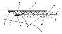
- FIG. 1shows a partial cross-section view through a shroud with impact cooling plate
- FIG. 2shows a partial cross-section view through a known shroud (state of the art)
- FIG. 3shows a partial cross-section view through a shroud with an impact cooling plate having elevations and recesses.
- FIG. 4shows a detailed view of a pressing connection between a cover plate and an impact cooling plate.
- FIG. 1is a schematic illustration of a partial cross-section view through the shroud 1 of a turbine blade.
- the shroud 1is joined with a cover plate 2 , preferably by way of a high-temperature soldering connection 3 .
- a cooling channel system 4is provided, which is covered by an impact cooling plate 5 .
- the impact cooling plate 5is pressed by force between the cover plate 2 and the shroud 1 by means of a spacer piece 6 .
- the spacer element 6extends over the entire circumferential area of the impact cooling plate 5 and presses the impact cooling plate 5 with a joining force that is adjustable via the cover plate 2 against the support surface 7 on the shroud 1 .
- a sealing element 8is also provided, which on the one hand is used for a gas-tight termination and, on the other hand, for an improved clamping effect, in particular transversely to the pressing force.
- the impact cooling plate 5has flow passage openings 9 with a narrowed flow cross-section, through which cooling air passes, depending on the pressure conditions, from the cooling channels 4 in the direction of the cover plate 2 or, in the reverse direction, in the form of a local impact cooling plate, and in this way results in an improved cooling effect.
- a spring-like, gas-permeable element 10is preferably provided, which additionally presses the impact cooling plate against the cooling channel wall structures 11 in a gas-tight manner.
- the joining force with which the impact cooling plate 5 is joined by force between the cover plate 2 and the shroud 1preferably should be limited so that at least the impact cooling plate 5 is kept free of bending tensions in the path of its thermal expansion.
- the spacer element 6is manufactured from an elastically or plastically deformable material, so that the spacer element 6 is elastically deformed when a maximum joining force is exceeded, so that an exceeding of the joining force onto the impact cooling plate 5 is not further transferred.
- FIG. 3shows a comparable partial cross-section view analogous to FIG. 1; however, the impact cooling plate 5 has bead-like deformations 12 .
- the impact cooling plate 5rests via a bead 12 constructed as a recess extending along the circumferential edge of the impact cooling plate on the support surface 7 of the shroud 1 .
- a sealing surface(not shown) in the area of the support surface of the bead 12 , a gas-tight termination can be ensured between the impact cooling plate 5 and the shroud 1 .
- a bead 12 ′constructed as an elevation is provided, where said bead contacts the underside of the cover plate 2 and thus presses the impact cooling plate 5 centrally against the cooling channels of the shroud 1 .
- Additional spacer elements 6can be used to further fixate the impact cooling plate 5 .
- FIG. 4shows a detail view of a pressing connection between a cover plate 2 and the impact cooling plate 5 .
- the edge area of the impact cooling plate 5is hereby constructed in a beaded manner and has an elastic spacer element 13 in the beaded area.
- the previously described spacer element 6is again placed between the cover plate 2 and the impact cooling plate 5 .
Landscapes
- Engineering & Computer Science (AREA)
- Mechanical Engineering (AREA)
- General Engineering & Computer Science (AREA)
- Turbine Rotor Nozzle Sealing (AREA)
Abstract
Description
Claims (9)
Applications Claiming Priority (3)
| Application Number | Priority Date | Filing Date | Title |
|---|---|---|---|
| DE10062907 | 2000-12-16 | ||
| DE10062907.5 | 2000-12-16 | ||
| DE10062907 | 2000-12-16 |
Publications (2)
| Publication Number | Publication Date |
|---|---|
| US20020136635A1 US20020136635A1 (en) | 2002-09-26 |
| US6589011B2true US6589011B2 (en) | 2003-07-08 |
Family
ID=7667527
Family Applications (2)
| Application Number | Title | Priority Date | Filing Date |
|---|---|---|---|
| US09/996,693Expired - LifetimeUS6589011B2 (en) | 2000-12-16 | 2001-11-30 | Device for cooling a shroud of a gas turbine blade |
| US09/996,684Expired - Fee RelatedUS6682304B2 (en) | 2000-12-16 | 2001-11-30 | Cooled gas turbine blade |
Family Applications After (1)
| Application Number | Title | Priority Date | Filing Date |
|---|---|---|---|
| US09/996,684Expired - Fee RelatedUS6682304B2 (en) | 2000-12-16 | 2001-11-30 | Cooled gas turbine blade |
Country Status (4)
| Country | Link |
|---|---|
| US (2) | US6589011B2 (en) |
| EP (2) | EP1215363B1 (en) |
| JP (1) | JP2002201907A (en) |
| DE (4) | DE10131073A1 (en) |
Cited By (3)
| Publication number | Priority date | Publication date | Assignee | Title |
|---|---|---|---|---|
| US20110110772A1 (en)* | 2009-11-11 | 2011-05-12 | Arrell Douglas J | Turbine Engine Components with Near Surface Cooling Channels and Methods of Making the Same |
| US10370300B2 (en)* | 2017-10-31 | 2019-08-06 | General Electric Company | Additively manufactured turbine shroud segment |
| US11371372B2 (en)* | 2014-09-09 | 2022-06-28 | Raytheon Technologies Corporation | Beveled coverplate |
Families Citing this family (8)
| Publication number | Priority date | Publication date | Assignee | Title |
|---|---|---|---|---|
| EP2098977B1 (en) | 2002-05-09 | 2012-11-21 | Sony Corporation | Method of detecting biological pattern, biological pattern detector, method of biological certificate and biological certificate apparatus |
| EP1789654B1 (en) | 2004-09-16 | 2017-08-23 | General Electric Technology GmbH | Turbine engine vane with fluid cooled shroud |
| US20070048122A1 (en)* | 2005-08-30 | 2007-03-01 | United Technologies Corporation | Debris-filtering technique for gas turbine engine component air cooling system |
| US9133724B2 (en)* | 2012-01-09 | 2015-09-15 | General Electric Company | Turbomachine component including a cover plate |
| US9567857B2 (en) | 2013-03-08 | 2017-02-14 | Rolls-Royce North American Technologies, Inc. | Turbine split ring retention and anti-rotation method |
| DE102017208680A1 (en) | 2017-05-23 | 2018-11-29 | Siemens Aktiengesellschaft | Method of attaching a cooling plate to a turbine blade |
| US11156102B2 (en)* | 2018-03-19 | 2021-10-26 | General Electric Company | Blade having a tip cooling cavity and method of making same |
| CN114405715B (en)* | 2021-12-28 | 2023-08-18 | 东方电气集团东方汽轮机有限公司 | Clamping tool for spraying hollow blade of gas turbine |
Citations (11)
| Publication number | Priority date | Publication date | Assignee | Title |
|---|---|---|---|---|
| US3756020A (en)* | 1972-06-26 | 1973-09-04 | Curtiss Wright Corp | Gas turbine engine and cooling system therefor |
| US3781129A (en)* | 1972-09-15 | 1973-12-25 | Gen Motors Corp | Cooled airfoil |
| US4086757A (en)* | 1976-10-06 | 1978-05-02 | Caterpillar Tractor Co. | Gas turbine cooling system |
| US4162136A (en)* | 1974-04-05 | 1979-07-24 | Rolls-Royce Limited | Cooled blade for a gas turbine engine |
| US4712979A (en) | 1985-11-13 | 1987-12-15 | The United States Of America As Represented By The Secretary Of The Air Force | Self-retained platform cooling plate for turbine vane |
| US4752184A (en)* | 1986-05-12 | 1988-06-21 | The United States Of America As Represented By The Secretary Of The Air Force | Self-locking outer air seal with full backside cooling |
| US5743708A (en)* | 1994-08-23 | 1998-04-28 | General Electric Co. | Turbine stator vane segments having combined air and steam cooling circuits |
| US5967743A (en)* | 1996-10-23 | 1999-10-19 | Asea Brown Boveri Ag | Blade carrier for a compressor |
| US6179555B1 (en)* | 1998-10-06 | 2001-01-30 | Pratt & Whitney Canada Corp. | Sealing of T.O.B.I feed plenum |
| US6179557B1 (en)* | 1998-07-18 | 2001-01-30 | Rolls-Royce Plc | Turbine cooling |
| US20020018715A1 (en)* | 2000-08-12 | 2002-02-14 | Dailey Geoffrey M. | Turbine blade support assembly and a turbine assembly |
Family Cites Families (7)
| Publication number | Priority date | Publication date | Assignee | Title |
|---|---|---|---|---|
| NL88170C (en)* | 1952-10-31 | 1900-01-01 | ||
| US4017209A (en)* | 1975-12-15 | 1977-04-12 | United Technologies Corporation | Turbine rotor construction |
| US5350277A (en)* | 1992-11-20 | 1994-09-27 | General Electric Company | Closed-circuit steam-cooled bucket with integrally cooled shroud for gas turbines and methods of steam-cooling the buckets and shrouds |
| JP3188105B2 (en) | 1994-07-11 | 2001-07-16 | 三菱重工業株式会社 | Gas turbine blades |
| JP3316415B2 (en)* | 1997-05-01 | 2002-08-19 | 三菱重工業株式会社 | Gas turbine cooling vane |
| JP2955252B2 (en)* | 1997-06-26 | 1999-10-04 | 三菱重工業株式会社 | Gas turbine blade tip shroud |
| US6454526B1 (en)* | 2000-09-28 | 2002-09-24 | Siemens Westinghouse Power Corporation | Cooled turbine vane with endcaps |
- 2001
- 2001-06-27DEDE10131073Apatent/DE10131073A1/ennot_activeWithdrawn
- 2001-06-28DEDE10131370Apatent/DE10131370A1/ennot_activeWithdrawn
- 2001-11-30USUS09/996,693patent/US6589011B2/ennot_activeExpired - Lifetime
- 2001-11-30DEDE50106966Tpatent/DE50106966D1/ennot_activeExpired - Lifetime
- 2001-11-30EPEP01128573Apatent/EP1215363B1/ennot_activeExpired - Lifetime
- 2001-11-30USUS09/996,684patent/US6682304B2/ennot_activeExpired - Fee Related
- 2001-11-30DEDE50107607Tpatent/DE50107607D1/ennot_activeExpired - Lifetime
- 2001-11-30EPEP01128572Apatent/EP1215364B1/ennot_activeExpired - Lifetime
- 2001-12-17JPJP2001383503Apatent/JP2002201907A/enactivePending
Patent Citations (11)
| Publication number | Priority date | Publication date | Assignee | Title |
|---|---|---|---|---|
| US3756020A (en)* | 1972-06-26 | 1973-09-04 | Curtiss Wright Corp | Gas turbine engine and cooling system therefor |
| US3781129A (en)* | 1972-09-15 | 1973-12-25 | Gen Motors Corp | Cooled airfoil |
| US4162136A (en)* | 1974-04-05 | 1979-07-24 | Rolls-Royce Limited | Cooled blade for a gas turbine engine |
| US4086757A (en)* | 1976-10-06 | 1978-05-02 | Caterpillar Tractor Co. | Gas turbine cooling system |
| US4712979A (en) | 1985-11-13 | 1987-12-15 | The United States Of America As Represented By The Secretary Of The Air Force | Self-retained platform cooling plate for turbine vane |
| US4752184A (en)* | 1986-05-12 | 1988-06-21 | The United States Of America As Represented By The Secretary Of The Air Force | Self-locking outer air seal with full backside cooling |
| US5743708A (en)* | 1994-08-23 | 1998-04-28 | General Electric Co. | Turbine stator vane segments having combined air and steam cooling circuits |
| US5967743A (en)* | 1996-10-23 | 1999-10-19 | Asea Brown Boveri Ag | Blade carrier for a compressor |
| US6179557B1 (en)* | 1998-07-18 | 2001-01-30 | Rolls-Royce Plc | Turbine cooling |
| US6179555B1 (en)* | 1998-10-06 | 2001-01-30 | Pratt & Whitney Canada Corp. | Sealing of T.O.B.I feed plenum |
| US20020018715A1 (en)* | 2000-08-12 | 2002-02-14 | Dailey Geoffrey M. | Turbine blade support assembly and a turbine assembly |
Cited By (3)
| Publication number | Priority date | Publication date | Assignee | Title |
|---|---|---|---|---|
| US20110110772A1 (en)* | 2009-11-11 | 2011-05-12 | Arrell Douglas J | Turbine Engine Components with Near Surface Cooling Channels and Methods of Making the Same |
| US11371372B2 (en)* | 2014-09-09 | 2022-06-28 | Raytheon Technologies Corporation | Beveled coverplate |
| US10370300B2 (en)* | 2017-10-31 | 2019-08-06 | General Electric Company | Additively manufactured turbine shroud segment |
Also Published As
| Publication number | Publication date |
|---|---|
| DE10131370A1 (en) | 2002-06-20 |
| US6682304B2 (en) | 2004-01-27 |
| EP1215364A2 (en) | 2002-06-19 |
| EP1215363B1 (en) | 2005-10-05 |
| JP2002201907A (en) | 2002-07-19 |
| DE50107607D1 (en) | 2006-02-16 |
| US20020136635A1 (en) | 2002-09-26 |
| EP1215364A3 (en) | 2004-01-02 |
| EP1215364B1 (en) | 2005-08-03 |
| EP1215363A3 (en) | 2004-01-02 |
| EP1215363A2 (en) | 2002-06-19 |
| DE50106966D1 (en) | 2005-09-08 |
| DE10131073A1 (en) | 2002-06-20 |
| US20020127103A1 (en) | 2002-09-12 |
Similar Documents
| Publication | Publication Date | Title |
|---|---|---|
| US6589011B2 (en) | Device for cooling a shroud of a gas turbine blade | |
| JP4648575B2 (en) | Floating pulley cup collision baffle | |
| US7270175B2 (en) | Extended impingement cooling device and method | |
| JP4047560B2 (en) | Side-by-side blade platform pair ventilation system | |
| JP5110646B2 (en) | Casing between turbines provided with cooling circuit and turbofan provided with the same | |
| US6237344B1 (en) | Dimpled impingement baffle | |
| US8851845B2 (en) | Turbomachine vane and method of cooling a turbomachine vane | |
| US4749298A (en) | Temperature resistant fastener arrangement | |
| CA1115640A (en) | Turbine seal and vane damper | |
| US7341429B2 (en) | Methods and apparatuses for cooling gas turbine engine rotor assemblies | |
| US8206109B2 (en) | Turbine blade assemblies with thermal insulation | |
| US10100737B2 (en) | Impingement cooling arrangement having a snap-in plate | |
| US20100040479A1 (en) | Gas Turbine Engine Systems Involving Baffle Assemblies | |
| JP5990639B2 (en) | Gas turbine shaft rotor | |
| JP4052376B2 (en) | Method and apparatus for sealing a gas turbine engine variable nozzle | |
| JP4532052B2 (en) | Method for sealing thermally loaded walls and wall gaps | |
| CA2264076C (en) | Gas turbine moving blade tip shroud | |
| US8764395B2 (en) | Blade for a gas turbine | |
| JP2000192802A (en) | Circumferential wall which can be cooled of gas turbine or the like | |
| JP2003525381A (en) | Turbine equipment | |
| US5407133A (en) | Cooled thin metal liner | |
| EP3263840B1 (en) | Transition part assembly and combustor including the same | |
| JP2005133712A (en) | Method and apparatus to reduce turbine engine nozzle base sheet stress | |
| JPH0648092B2 (en) | Combustion chamber structure | |
| CN102066840A (en) | Heat shield device |
Legal Events
| Date | Code | Title | Description |
|---|---|---|---|
| AS | Assignment | Owner name:ALSTOM (SWITZERLAND) LTD, SWITZERLAND Free format text:ASSIGNMENT OF ASSIGNORS INTEREST;ASSIGNORS:BEECK, ALEXANDER;FRIED, REINHARD;OEHL, MARKUS;REEL/FRAME:012814/0212 Effective date:20020408 | |
| STCF | Information on status: patent grant | Free format text:PATENTED CASE | |
| AS | Assignment | Owner name:ALSTOM TECHNOLOGY LTD, SWITZERLAND Free format text:ASSIGNMENT OF ASSIGNORS INTEREST;ASSIGNOR:ALSTOM (SWITZERLAND) LTD;REEL/FRAME:014770/0783 Effective date:20031101 | |
| FPAY | Fee payment | Year of fee payment:4 | |
| FPAY | Fee payment | Year of fee payment:8 | |
| FPAY | Fee payment | Year of fee payment:12 | |
| AS | Assignment | Owner name:GENERAL ELECTRIC TECHNOLOGY GMBH, SWITZERLAND Free format text:CHANGE OF NAME;ASSIGNOR:ALSTOM TECHNOLOGY LTD;REEL/FRAME:038216/0193 Effective date:20151102 | |
| AS | Assignment | Owner name:ANSALDO ENERGIA SWITZERLAND AG, SWITZERLAND Free format text:ASSIGNMENT OF ASSIGNORS INTEREST;ASSIGNOR:GENERAL ELECTRIC TECHNOLOGY GMBH;REEL/FRAME:041686/0884 Effective date:20170109 |