US6588866B2 - Slide rail attachment - Google Patents
Slide rail attachmentDownload PDFInfo
- Publication number
- US6588866B2 US6588866B2US09/844,479US84447901AUS6588866B2US 6588866 B2US6588866 B2US 6588866B2US 84447901 AUS84447901 AUS 84447901AUS 6588866 B2US6588866 B2US 6588866B2
- Authority
- US
- United States
- Prior art keywords
- rail member
- latch
- securement
- component chassis
- chassis
- Prior art date
- Legal status (The legal status is an assumption and is not a legal conclusion. Google has not performed a legal analysis and makes no representation as to the accuracy of the status listed.)
- Expired - Fee Related, expires
Links
- 230000013011matingEffects0.000claimsabstractdescription12
- 229910000639Spring steelInorganic materials0.000claimsdescription2
- 238000000034methodMethods0.000claims12
- 230000008878couplingEffects0.000claims3
- 238000010168coupling processMethods0.000claims3
- 238000005859coupling reactionMethods0.000claims3
- 238000000926separation methodMethods0.000claims2
- 229910000831SteelInorganic materials0.000description2
- 238000005096rolling processMethods0.000description2
- 239000010959steelSubstances0.000description2
- 238000012423maintenanceMethods0.000description1
- 239000000463materialSubstances0.000description1
- 239000002184metalSubstances0.000description1
Images


Classifications
- G—PHYSICS
- G11—INFORMATION STORAGE
- G11B—INFORMATION STORAGE BASED ON RELATIVE MOVEMENT BETWEEN RECORD CARRIER AND TRANSDUCER
- G11B33/00—Constructional parts, details or accessories not provided for in the other groups of this subclass
- G11B33/12—Disposition of constructional parts in the apparatus, e.g. of power supply, of modules
- G11B33/125—Disposition of constructional parts in the apparatus, e.g. of power supply, of modules the apparatus comprising a plurality of recording/reproducing devices, e.g. modular arrangements, arrays of disc drives
- G11B33/127—Mounting arrangements of constructional parts onto a chassis
- G11B33/128—Mounting arrangements of constructional parts onto a chassis of the plurality of recording/reproducing devices, e.g. disk drives, onto a chassis
- H—ELECTRICITY
- H05—ELECTRIC TECHNIQUES NOT OTHERWISE PROVIDED FOR
- H05K—PRINTED CIRCUITS; CASINGS OR CONSTRUCTIONAL DETAILS OF ELECTRIC APPARATUS; MANUFACTURE OF ASSEMBLAGES OF ELECTRICAL COMPONENTS
- H05K7/00—Constructional details common to different types of electric apparatus
- H05K7/14—Mounting supporting structure in casing or on frame or rack
- H05K7/1485—Servers; Data center rooms, e.g. 19-inch computer racks
- H05K7/1488—Cabinets therefor, e.g. chassis or racks or mechanical interfaces between blades and support structures
- H05K7/1489—Cabinets therefor, e.g. chassis or racks or mechanical interfaces between blades and support structures characterized by the mounting of blades therein, e.g. brackets, rails, trays
Definitions
- This inventionrelates to the attachment of slide rails, such as for extendable rack-mounted electronic components, and such.
- Computer systemsare frequently comprised of several discrete components, each packaged in a serviceable box or chassis of a common width and one of various standard heights.
- Several such components of a systemmay be mounted in a rack designed to enable the components to be individually removed for service or replacement.
- Flanges of the componentsmay be bolted, for example, in any number of positions along a vertical series of holes along the rack.
- some computer server componentshave been mounted into racks on extendable slide rails, such as are employed on desk and cabinet drawers.
- One elongated portion of a railis firmly attached to the server component chassis, such as by screws, and a mating portion of the rail is rigidly secured to the rack.
- the two mating portions of the railcan slide in relation to each other on bearing surfaces, between stops, to enable the component to be readily pulled partially from the rack for maintenance or service.
- the two mating portions of some slide railscan be disconnected from each other to completely remove the server component, with its portions of two corresponding slide rails still attached, from the rack.
- FIG. 1is a perspective view of a component rack.
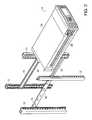
- FIG. 2shows the mounting of a component chassis to a rack with two slide rails.
- FIG. 3is an exploded, perspective view of a three-section, quick-release slide rail.
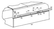
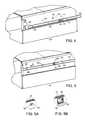
- FIGS. 4 and 5illustrate the mounting of the inner slide rail member to a component chassis.
- FIGS. 5A and 5Bare enlarged views of areas 5 A and 5 B, respectively, of FIG. 5 .
- FIG. 6Ashows detail of the keyhole slot seen in FIG. 5 A.
- FIG. 6Bis a cross-sectional view through a standoff projection, taken along line 6 B— 6 B in FIG. 4 .
- FIG. 7is a perspective view of a spring clip.
- FIGS. 8 and 9are face and side views, respectively, of the spring clip of FIG. 7 .
- a rack 10 as known in the arthas four upright, metal beams 12 provided with corresponding series of mounting holes for mounting brackets and rails supporting computer and other electronic equipment at various elevations in the rack.
- the beam and hole spacing of such rackshas become somewhat standard in the industry.
- a single computer component 14is mounted to the upright beams 12 of the rack with a pair of extendable slides 16 .
- Each slide 16consists of three elongated members forming a telescoping assembly.
- An outer member 18is mounted rigidly between two upright beams 12 on each side of the rack, such as by threaded fasteners.
- An intermediate member 20travels within a track defined by outer member 18 , on a series of roller bearings. When fully extended, the travel of intermediate member 20 is limited by a mechanical stop (not visible in this view). When retracted, the intermediate member is contained within the length of the outer member 18 .
- An inner member 22(shown detached from the rest of the slide rail) is rigidly secured to the chassis 24 of component 14 , by means described more fully below.
- To install component 14 into the rackits attached inner slide members 22 are slid into the intermediate members 20 that are already secured in the outer members 18 attached to the rack.
- component 14can be pulled from the rack by extending the slides 16 . If more extensive service or replacement is required, however, inner members 22 can be slid out of their respective intermediate slide members 20 to completely remove the component from the rack, without disassembling the inner slide members 22 from the component chassis 24 or detaching the outer slide members 18 from the rack.
- Outer slide member 18may be rigidly secured to the rack by any appropriate attachment means, such as threaded fasteners, rivets or quick-release pins.
- the outer slide membermay be permanently secured to the rack, if desired, although it is preferably removable for replacement or repositioning.
- Outer slide member 18includes two spaced-apart brackets 26 with holed flanges for mounting the slide in a rack.
- An rear stop 28limits the travel of intermediate member 20 in one direction, while a releasable catch 28 of the intermediate member engages a tab (not shown) along the web of outer member 18 when the intermediate member is fully extended, to limit travel in the other direction.
- Catch 28is pivotably attached to intermediate member 20 , and latches intermediate member 20 to outer member 18 at full extension.
- inner member 22When inner member 22 has been fully retracted, it engages and rotates catch 28 to enable subsequent retraction of intermediate member 20 , ensuring sequential retraction.
- Multiple bearing balls 30are held within ball retainer 32 to provide for rolling contact between intermediate member 20 and inner member 22 .
- a similar retainer and series of ballsform the rolling interface between intermediate member 20 and outer member 18 .
- a spring clip 34extends from the outboard side of the web of inner member 22 to engage the edge of a hole 36 through the web of intermediate member 20 when the inner member is fully extended. Once fully extended, the engagement of clip 34 with hole 36 also prohibits retraction of the inner member within the intermediate member without manually compressing clip 34 for disengagement. A distal, free end 38 of clip 34 is exposed beyond the web of intermediate member 20 with the inner member fully extended, for manipulation. Manually compressing and disengaging clip 34 also releases inner member 22 for complete removal from the intermediate member.
- Inner member 22is also provided with three keyhole slots 40 through its central web, and a single aperture 42 , for quick mounting of the inner member to a component housing without the use of tools, as illustrated in FIGS. 4 and 5.
- Housing 24has a corresponding series of three standoff projections 44 that are received in enlarged ends of keyhole slots 40 , and a spring clip 46 (described in more detail below) exposed through an aperture 48 through the housing wall to engage an edge of aperture 42 of the inner slide member 22 .
- the inner slide rail member 22is moved toward the side of the component housing 24 in a normal direction until the heads of projections 44 have passed through the larger ends of keyhole slots 40 (FIG. 4 ), the inner slide rail member 22 is slid forward along component housing 24 in the direction of arrow “A” (FIG. 5) until spring clip 46 snaps into aperture 42 of the inner rail member (see also FIG. 5B) to secure the inner rail member against being slid in the opposite direction, with the heads of projections 44 overlapping the web of the inner rail member in the vicinity of keyhole slots 40 (see also FIG. 5A) to retain the inner member against the side of the component housing.
- FIG. 6Ashows the profile of the keyhole slots 40 of the inner slide member.
- the larger endhas a radius R 1 of about 0.155 inch (3.94 millimeters), while the smaller end has a radius R 2 of about 0.1 inch (2.5 millimeters).
- the centers of the arcs defining the two endsare separated by a distance “D” of about 0.3 inch (7.6 millimeters).
- the structure of one of the corresponding steel standoff projections 44is shown in FIG. 6 B.
- the circular standoffhas a head 50 with an overall diameter of about 0.275 inch (7.0 millimeters) and a thickness of about 0.1 inch (2.5 millimeters).
- This headis integrally formed with a stem 52 having a diameter of about 0.195 inch (5.0 millimeters) that is knurled and pressed into a hole in the component housing wall until the inner end of the stem is flush with the inner surface 54 of the housing 24 , which is formed of steel having a nominal wall thickness of about 0.48 inch (12 millimeters).
- the inner surface of head 50 of projection 44is disposed about 0.05 inch (1.3 millimeters) from the outer surface of the housing, for receiving the nominal thickness of the web of the inner slide member beneath the projection head.
- head 52has a thickness of only about 0.1 inch (2.5 millimeters), in the final assembly it extends only about 0.1 inch (2.5 millimeters) beyond the outer surface of the inner slide member and does not interfere with the retraction of the inner slide member within the intermediate slide member.
- the dimensional tolerances, and nominal clearance between projection 44 and the inner slide member keyhole slot,should be chosen to minimize free play in the final assembly, while still enabling assembly by hand.
- elongated spring clip 46is formed of 1 ⁇ 4-hard spring steel having a nominal thickness “t” of about 0.025 inch (0.64 millimeter).
- Two holes 56 through the clipare for permanently securing the clip to the inner surface of the component housing, either by threaded fasteners, rivets, staking or other attachment means.
- Spaced longitudinally from holes 56is a raised wedge 58 having length “L” of about 0.56 inch (14 millimeters) and height “H” of about 0.15 inch (3.8 millimeters), formed of the same sheet stock by a punch-forming operation.
- Wedge 58has a distal edge 60 for engaging the edge of the aperture in the inner slide member web.
- the length of clip 46 between holes 56 and wedge 58enables the clip to be flexed out of its plane to deflect into the component housing as the inner slide member web is pressed against wedge 58 .
- the resiliency of the materialcauses wedge 58 to spring back to its original position once aligned with inner member aperture 42 (see FIG. 5 B).
- a spring clipsuch as a plunger alignable with a hole
- the keyhole slots and standoffsmay be fashioned of many different profiles and structures, enabling different motion sequences and directions for attaching the inner rail member.
- the standoffscan be secured to the inner slide member, with corresponding keyhole slots in the component housing.
- Multiple spring clipsmay be employed to further reduce any risk of inadvertent release.
Landscapes
- Engineering & Computer Science (AREA)
- Computer Hardware Design (AREA)
- General Engineering & Computer Science (AREA)
- Microelectronics & Electronic Packaging (AREA)
- Drawers Of Furniture (AREA)
Abstract
Description
This invention relates to the attachment of slide rails, such as for extendable rack-mounted electronic components, and such.
Computer systems are frequently comprised of several discrete components, each packaged in a serviceable box or chassis of a common width and one of various standard heights. Several such components of a system may be mounted in a rack designed to enable the components to be individually removed for service or replacement. Flanges of the components may be bolted, for example, in any number of positions along a vertical series of holes along the rack.
To improve serviceability, some computer server components have been mounted into racks on extendable slide rails, such as are employed on desk and cabinet drawers. One elongated portion of a rail is firmly attached to the server component chassis, such as by screws, and a mating portion of the rail is rigidly secured to the rack. The two mating portions of the rail can slide in relation to each other on bearing surfaces, between stops, to enable the component to be readily pulled partially from the rack for maintenance or service. The two mating portions of some slide rails can be disconnected from each other to completely remove the server component, with its portions of two corresponding slide rails still attached, from the rack.
FIG. 1 is a perspective view of a component rack.
FIG. 2 shows the mounting of a component chassis to a rack with two slide rails.
FIG. 3 is an exploded, perspective view of a three-section, quick-release slide rail.
FIGS. 4 and 5 illustrate the mounting of the inner slide rail member to a component chassis.
FIGS. 5A and 5B are enlarged views ofareas
FIG. 6A shows detail of the keyhole slot seen in FIG.5A.
FIG. 6B is a cross-sectional view through a standoff projection, taken alongline 6B—6B in FIG.4.
FIG. 7 is a perspective view of a spring clip.
FIGS. 8 and 9 are face and side views, respectively, of the spring clip of FIG.7.
In FIG. 1, arack 10 as known in the art has four upright,metal beams 12 provided with corresponding series of mounting holes for mounting brackets and rails supporting computer and other electronic equipment at various elevations in the rack. The beam and hole spacing of such racks has become somewhat standard in the industry.
As shown in FIG. 2, asingle computer component 14 is mounted to theupright beams 12 of the rack with a pair ofextendable slides 16. Eachslide 16 consists of three elongated members forming a telescoping assembly. Anouter member 18 is mounted rigidly between twoupright beams 12 on each side of the rack, such as by threaded fasteners. Anintermediate member 20 travels within a track defined byouter member 18, on a series of roller bearings. When fully extended, the travel ofintermediate member 20 is limited by a mechanical stop (not visible in this view). When retracted, the intermediate member is contained within the length of theouter member 18. An inner member22 (shown detached from the rest of the slide rail) is rigidly secured to thechassis 24 ofcomponent 14, by means described more fully below. To installcomponent 14 into the rack, its attachedinner slide members 22 are slid into theintermediate members 20 that are already secured in theouter members 18 attached to the rack. For local service,component 14 can be pulled from the rack by extending theslides 16. If more extensive service or replacement is required, however,inner members 22 can be slid out of their respectiveintermediate slide members 20 to completely remove the component from the rack, without disassembling theinner slide members 22 from thecomponent chassis 24 or detaching theouter slide members 18 from the rack.
More detail of theslide assembly 16 is visible in FIG.3.Outer slide member 18 includes two spaced-apart brackets 26 with holed flanges for mounting the slide in a rack. Anrear stop 28 limits the travel ofintermediate member 20 in one direction, while areleasable catch 28 of the intermediate member engages a tab (not shown) along the web ofouter member 18 when the intermediate member is fully extended, to limit travel in the other direction. Catch28 is pivotably attached tointermediate member 20, and latchesintermediate member 20 toouter member 18 at full extension. Wheninner member 22 has been fully retracted, it engages and rotatescatch 28 to enable subsequent retraction ofintermediate member 20, ensuring sequential retraction.Multiple bearing balls 30 are held withinball retainer 32 to provide for rolling contact betweenintermediate member 20 andinner member 22. A similar retainer and series of balls (not shown) form the rolling interface betweenintermediate member 20 andouter member 18.
Aspring clip 34 extends from the outboard side of the web ofinner member 22 to engage the edge of ahole 36 through the web ofintermediate member 20 when the inner member is fully extended. Once fully extended, the engagement ofclip 34 withhole 36 also prohibits retraction of the inner member within the intermediate member without manually compressingclip 34 for disengagement. A distal,free end 38 ofclip 34 is exposed beyond the web ofintermediate member 20 with the inner member fully extended, for manipulation. Manually compressing and disengagingclip 34 also releasesinner member 22 for complete removal from the intermediate member.
After the innerslide rail member 22 is moved toward the side of thecomponent housing 24 in a normal direction until the heads ofprojections 44 have passed through the larger ends of keyhole slots40 (FIG.4), the innerslide rail member 22 is slid forward alongcomponent housing 24 in the direction of arrow “A” (FIG. 5) untilspring clip 46 snaps intoaperture 42 of the inner rail member (see also FIG. 5B) to secure the inner rail member against being slid in the opposite direction, with the heads ofprojections 44 overlapping the web of the inner rail member in the vicinity of keyhole slots40 (see also FIG. 5A) to retain the inner member against the side of the component housing.
FIG. 6A shows the profile of thekeyhole slots 40 of the inner slide member. The larger end has a radius R1of about 0.155 inch (3.94 millimeters), while the smaller end has a radius R2of about 0.1 inch (2.5 millimeters). The centers of the arcs defining the two ends are separated by a distance “D” of about 0.3 inch (7.6 millimeters).
The structure of one of the correspondingsteel standoff projections 44 is shown in FIG.6B. The circular standoff has ahead 50 with an overall diameter of about 0.275 inch (7.0 millimeters) and a thickness of about 0.1 inch (2.5 millimeters). This head is integrally formed with astem 52 having a diameter of about 0.195 inch (5.0 millimeters) that is knurled and pressed into a hole in the component housing wall until the inner end of the stem is flush with theinner surface 54 of thehousing 24, which is formed of steel having a nominal wall thickness of about 0.48 inch (12 millimeters). Once assembled to the component housing, the inner surface ofhead 50 ofprojection 44 is disposed about 0.05 inch (1.3 millimeters) from the outer surface of the housing, for receiving the nominal thickness of the web of the inner slide member beneath the projection head. Becausehead 52 has a thickness of only about 0.1 inch (2.5 millimeters), in the final assembly it extends only about 0.1 inch (2.5 millimeters) beyond the outer surface of the inner slide member and does not interfere with the retraction of the inner slide member within the intermediate slide member. The dimensional tolerances, and nominal clearance betweenprojection 44 and the inner slide member keyhole slot, should be chosen to minimize free play in the final assembly, while still enabling assembly by hand.
Referring now to FIGS. 7-9,elongated spring clip 46 is formed of ¼-hard spring steel having a nominal thickness “t” of about 0.025 inch (0.64 millimeter). Twoholes 56 through the clip are for permanently securing the clip to the inner surface of the component housing, either by threaded fasteners, rivets, staking or other attachment means. Spaced longitudinally fromholes 56 is a raisedwedge 58 having length “L” of about 0.56 inch (14 millimeters) and height “H” of about 0.15 inch (3.8 millimeters), formed of the same sheet stock by a punch-forming operation.Wedge 58 has adistal edge 60 for engaging the edge of the aperture in the inner slide member web. The length ofclip 46 betweenholes 56 andwedge 58 enables the clip to be flexed out of its plane to deflect into the component housing as the inner slide member web is pressed againstwedge 58. The resiliency of the material causeswedge 58 to spring back to its original position once aligned with inner member aperture42 (see FIG.5B).
Other embodiments are within the scope of the following claims. For example, other hand-manipulable or automatic locking means may be employed instead of a spring clip, such as a plunger alignable with a hole, to lock the inner slide member to the component housing once slid into position. The keyhole slots and standoffs may be fashioned of many different profiles and structures, enabling different motion sequences and directions for attaching the inner rail member. The standoffs can be secured to the inner slide member, with corresponding keyhole slots in the component housing. Multiple spring clips may be employed to further reduce any risk of inadvertent release. These are but a few of the variations that are envisioned within the spirit and scope of the invention as claimed.
Claims (22)
1. Apparatus comprising:
a first elongated rail member attachable to a rack defining an opening sized to slidingly receive an electronic system component chassis; and
a second elongated rail member attachable to the component chassis, the second rail member configured for sliding coupling with the first rail member to enable the chassis to be moved with respect to the rack;
the second rail member having a quick-connect feature adapted to engage a mating feature of the component chassis to secure the second rail member to the chassis,
the quick-connect feature being adapted to receive said mating feature of the component chassis in a first engagement position, and then to slide with respect to the mating feature in a direction extending along the second rail member, to a securement position to secure the second rail member to the chassis,
one of the second rail member and the component chassis comprising a securement latch positioned to engage a corresponding latch receiver of the other of the second rail member and the component chassis when the quick-connect feature is in its securement position, to restrict relative motion between, and separation of, the second rail member and the component chassis, the securement latch being biased toward the other of the second rail member and the component chassis, for automatically seating the securement latch upon alignment of the securement latch and latch receiver,
the securement latch being attached to a side of one of the second rail member and the component chassis that is facing away from the other of the second rail member and the component chassis, the securement latch comprising an inclined surface that rises from a narrower leading end to a broader trailing end, the one of the second rail member and the component chassis having an opening to allow the inclined surface to protrude from the side of one of the second rail member and the component chassis towards the other of the second rail member and the component chassis, to cause the securement latch to be urged away from the other of the second rail member and the component chassis as the quick-connect feature is moved towards its securement position, the trailing end terminating in a stop edge that mates with the latch receiver to secure the second rail member to the chassis when the quick-connect feature reaches the securement position.
2. The apparatus ofclaim 1 further comprising a releasable extension stop for removing the second rail member from the first rail member.
3. The apparatus ofclaim 1 wherein one of the quick-connect feature and the mating feature comprises a headed protrusion, extending from a corresponding one of the second rail member and the component chassis, and wherein the other of the quick-connect feature and the mating feature comprises a slot sized to slidingly receive the protrusion.
4. The apparatus ofclaim 3 wherein the slot has a wide end for receiving an enlarged head of the protrusion into the slot, and a narrow end for retaining the protrusion once received.
5. The apparatus ofclaim 3 wherein the headed protrusion has a shank extending from a side of said corresponding one of the second rail member and the component chassis to a distal head overhanging said side.
6. The apparatus ofclaim 5 wherein the distal head has a thickness, measured in a direction perpendicular to said side, of less than about 0.15 inch.
7. The apparatus ofclaim 1 wherein the securement latch is of the component chassis, and the latch receiver is of the second rail member.
8. The apparatus ofclaim 7 wherein the latch receiver is in the form of a hole defined in the second rail member and spaced apart along the second rail member from the quick-connect feature.
9. Apparatus comprising:
a first elongated rail member attachable to a rack defining an opening sized to slidingly receive an electronic system component chassis; and
a second elongated rail member attachable to the component chassis, the second rail member configured for sliding coupling with the first rail member to enable the chassis to be moved with respect to the rack, the second rail member defining
multiple, longitudinally spaced apart, slotted holes positioned to receive corresponding headed protrusions of the component chassis in an engagement position, the slotted holes being elongated to enable the received protrusions to slide to a securement position, and
a latch-receiving hole positioned to align with and receive a securement latch of the component chassis when the protrusions are in their securement position, to secure the second rail member to the chassis,
the securement latch being attached to an inner side of component chassis facing away from the second rail member, the securement latch comprising an inclined surface that rises from a narrower leading end to a broader trailing end, the component chassis having an opening to allow the inclined surface to protrude from the inner side of the component chassis towards the second rail member, to cause the securement latch to be urged away from the second rail member as the securement latch is moved towards its securement position, the trailing end terminating in a stop edge that mates with the latch receiving hole to secure the second rail member to the chassis when the securement latch feature reaches the securement position.
10. The apparatus ofclaim 9 wherein each slotted hole has a wide end for receiving an enlarged head of the protrusion into the slot, and a narrow end for retaining the protrusion once received.
11. Apparatus comprising:
a first elongated rail member attachable to a rack defining an opening sized to slidingly receive an electronic system component chassis; and
a second elongated rail member attachable to the component chassis, the second rail member configured for sliding coupling with the first rail member to enable the chassis to be moved with respect to the rack;
the second rail member having means for connecting the second rail member to the component chassis by placing the second rail member against the component chassis in an engagement position, and then sliding the second rail member along the component chassis to a securement position, to longitudinally secure the second rail member to the chassis,
one of the second rail member and the component chassis comprising a securement latch positioned to engage a corresponding latch receiver of the other of the second rail member and the component chassis when the second rail member is in its securement position, to restrict relative motion between, and separation of, the second rail member and the component chassis, the securement latch being biased toward the other of the second rail member and the component chassis, for automatically seating the securement latch upon alignment of the securement latch and latch receiver,
the securement latch being attached to a side of one of the second rail member and the component chassis that is facing away from the other of the second rail member and the component chassis, the securement latch comprising an inclined surface that rises from a narrower leading end to a broader trailing end, the one of the second rail member and the component chassis having an opening to allow the inclined surface to protrude from the side of one of the second rail member and the component chassis towards the other of the second rail member and the component chassis, to cause the securement latch to be urged away from the other of the second rail member and the component chassis as second rail member is moved towards its securement position, the trailing end terminating in a stop edge that mates with the latch receiver to secure the second rail member to the chassis when the second rail member reaches the securement position.
12. The apparatus ofclaim 11 wherein said means for connecting the second rail member is adapted to secure the second rail member to the component chassis without tools.
13. A method of installing a component chassis into a rack, the method comprising:
securing a first elongated rail member of a slide rail to the rack;
securing a second elongated rail member of the slide rail to the component chassis by
engaging a quick-connect feature of the second rail member to a mating feature of the component chassis, and then
sliding the second rail member with respect to the component chassis to align a securement latch; and
attaching the first and second rail members of the slide rail to each other for slidable engagement,
the securement latch being positioned to engage a corresponding latch receiver, the securement latch being attached to a side of one of the second rail member and the component chassis that is facing away from the other of the second rail member and the component chassis, the securement latch being biased toward the other of the second rail member and the component chassis, for automatically seating the securement latch upon alignment of the securement latch and latch receiver, the securement latch comprising an inclined surface that rises from a narrower leading end to a broader trailing end, the one of the second rail member and the component chassis having an opening to allow the inclined surface to protrude from the side of one of the second rail member and the component chassis towards the other of the second rail member and the component chassis, to cause the securement latch to be urged away from the other of the second rail member or the component chassis as the second rail member is moved towards a securement position, the trailing end terminating in a stop edge that mates with the latch receiver to secure the second rail member to the chassis when the second rail member reaches the securement position.
14. The method ofclaim 13 wherein the second elongated rail member is secured to the component chassis before the first and second rail members of the slide rail are attached to each other.
15. The method ofclaim 13 wherein one of the quick-connect feature and the mating feature comprises a headed protrusion, extending from a corresponding one of the second rail member and the component chassis, and wherein the other of the quick-connect feature and the mating feature comprises a slot sized to slidingly receive the protrusion, the method including sliding the protrusion along the slot.
16. The method ofclaim 15 wherein the slot is has a wide end for receiving an enlarged head of the protrusion into the slot, and a narrow end for retaining the protrusion once received.
17. The method ofclaim 15 wherein the headed protrusion has a shank extending from a side of said corresponding one of the second rail member and the component chassis to a distal head overhanging said side.
18. The method ofclaim 17 herein the distal head has a thickness, measured in a direction perpendicular to said side, of less than about 0.15 inch.
19. The method ofclaim 13 wherein the securement latch is biased to automatically seat into the latch receiver when the latch and the latch receiver are longitudinally aligned.
20. The method ofclaim 19 wherein the securement latch is of the component chassis, and the latch receiver is of the second rail member.
21. The method ofclaim 20 wherein the latch receiver is in the form of a hole defined in the second rail member and spaced apart along the second rail member from the quick-connect feature.
22. The method ofclaim 20 wherein the securement latch comprises a spring steel clip secured to an inner surface of the component chassis and exposed for engagement with the latch receiver through an aperture in the component chassis.
Priority Applications (1)
| Application Number | Priority Date | Filing Date | Title |
|---|---|---|---|
| US09/844,479US6588866B2 (en) | 2001-04-27 | 2001-04-27 | Slide rail attachment |
Applications Claiming Priority (1)
| Application Number | Priority Date | Filing Date | Title |
|---|---|---|---|
| US09/844,479US6588866B2 (en) | 2001-04-27 | 2001-04-27 | Slide rail attachment |
Publications (2)
| Publication Number | Publication Date |
|---|---|
| US20020158556A1 US20020158556A1 (en) | 2002-10-31 |
| US6588866B2true US6588866B2 (en) | 2003-07-08 |
Family
ID=25292822
Family Applications (1)
| Application Number | Title | Priority Date | Filing Date |
|---|---|---|---|
| US09/844,479Expired - Fee RelatedUS6588866B2 (en) | 2001-04-27 | 2001-04-27 | Slide rail attachment |
Country Status (1)
| Country | Link |
|---|---|
| US (1) | US6588866B2 (en) |
Cited By (45)
| Publication number | Priority date | Publication date | Assignee | Title |
|---|---|---|---|---|
| US20010037985A1 (en)* | 1998-07-31 | 2001-11-08 | George Jordan | Computer component rack mounting arrangement |
| US20030052580A1 (en)* | 2001-09-19 | 2003-03-20 | Dobler Karl J. | Snap-on slide and rail assembly and method of assembling same |
| US20030141791A1 (en)* | 2001-12-12 | 2003-07-31 | William Dubon | Telescoping slide assembly |
| US20040000851A1 (en)* | 2002-05-17 | 2004-01-01 | Lian Lam Harn | Guide rails for pull-out drawer/equipment |
| US20040108797A1 (en)* | 2002-12-06 | 2004-06-10 | King Slide Works Co., Ltd. | Track set |
| US20040120123A1 (en)* | 2002-12-20 | 2004-06-24 | Mayer David W. | Multi-configurable telecommunications rack mounting system and method incorporating same |
| US20040159618A1 (en)* | 2003-02-19 | 2004-08-19 | Nguyen Minh H. | Removable rails for use on racks |
| US20040183410A1 (en)* | 2002-12-18 | 2004-09-23 | William Dubon | Telescoping slide rail with latching and alignment mechanisms |
| US20040217073A1 (en)* | 2003-05-01 | 2004-11-04 | Dobler Karl J. | System and method for utilizing a tool-less rail in a rack |
| US20040266597A1 (en)* | 2001-08-15 | 2004-12-30 | Melville Richard Archer | Rear service packaging apparatus |
| US20050088069A1 (en)* | 2003-10-24 | 2005-04-28 | Greenwald William B. | Telescoping slide assembly with quick-mount keyhole lock system |
| US20050196230A1 (en)* | 2004-01-16 | 2005-09-08 | Pentair Electronic Packaging Co. | Universal rack mounting connector and assembly |
| US6962397B2 (en) | 2001-09-19 | 2005-11-08 | Hewlett-Packard Development Company, L.P. | Expandable slide and rail assembly for a rack |
| US20050268823A1 (en)* | 2004-06-02 | 2005-12-08 | Bakker Mitchell R | Conference table |
| US20060091769A1 (en)* | 2002-12-18 | 2006-05-04 | William Dubon | Telescoping slide rail with latching and alignment mechanisms |
| US20070018547A1 (en)* | 2005-07-22 | 2007-01-25 | Shun-Ho Yang | Fast mounting mechanism for a telescoping slide |
| US20070070612A1 (en)* | 2005-09-23 | 2007-03-29 | Bull, S.A.S. | System for maintaining an assembly of three parts in position that exerts a predetermined compressive force on the itermediate part |
| US20070114895A1 (en)* | 2005-11-23 | 2007-05-24 | Ken-Ching Chen | Mount latch structure for a telescoping slide |
| DE102006014924A1 (en)* | 2006-03-30 | 2007-10-18 | Fujitsu Siemens Computers Gmbh | Slide-in device for server-rack, has guide rail arranged on side wall of rack, and pull-in aid provided with slanted guiding units in area of front opening of guide rail, where pull-in aid and guide rail are mounted on common support |
| US20080217497A1 (en)* | 2007-03-09 | 2008-09-11 | Hon Hai Precision Industry Co., Ltd. | Server rack |
| US20080259534A1 (en)* | 2007-04-18 | 2008-10-23 | Connor Lawrence T | Cassette matrix for an electrical switching apparatus |
| US20080259584A1 (en)* | 2007-04-18 | 2008-10-23 | Ostrowski Frankie K | Support and extension rail assembly |
| US20090219701A1 (en)* | 2008-02-29 | 2009-09-03 | Sui-An Wu | Sliding flat panel display and keyboard module |
| US20090289155A1 (en)* | 2008-05-23 | 2009-11-26 | Hong Fu Jin Precision Industry (Shenzhen) Co., Ltd | Slide rail assembly |
| USD612173S1 (en) | 2009-06-12 | 2010-03-23 | Nucraft Furniture Company | Table |
| US20110100935A1 (en)* | 2009-11-04 | 2011-05-05 | Inventec Corporation | Rail device and server |
| US8096244B1 (en) | 2007-06-06 | 2012-01-17 | Nucraft Furniture Company | Modular conference table |
| US8104850B2 (en) | 2007-05-30 | 2012-01-31 | Steelcase Inc. | Furniture storage unit |
| US20120063709A1 (en)* | 2010-09-10 | 2012-03-15 | King Slide Works Co., Ltd. | Slide assembly |
| US20120106880A1 (en)* | 2010-11-02 | 2012-05-03 | King Slide Works Co., Ltd. | Slide assembly with quick-mount system |
| US8358502B2 (en) | 2010-11-02 | 2013-01-22 | Hewlett-Packard Development Company, L.P. | Rack kit |
| US8366217B1 (en) | 2012-01-23 | 2013-02-05 | King Slide Works Co., Ltd. | Installation device for slide assembly |
| EP2612572A1 (en) | 2012-01-06 | 2013-07-10 | King Slide Works Co., Ltd. | Installation device for slide assembly |
| US8562085B2 (en) | 2011-08-08 | 2013-10-22 | King Slide Works Co. Ltd. | Installation device for slide assembly |
| US8622492B2 (en) | 2011-06-17 | 2014-01-07 | King Slide Works Co., Ltd. | Positioning mechanism for quick release device of slide assembly |
| DE102013108217B3 (en)* | 2013-07-31 | 2014-10-16 | Fujitsu Technology Solutions Intellectual Property Gmbh | Slot arrangement for a server rack, as well as holding device for attachment to a server rack |
| AT508819A3 (en)* | 2009-10-02 | 2015-11-15 | Hettich Paul Gmbh & Co Kg | LOCKING ARRANGEMENT |
| US9581182B2 (en)* | 2015-05-28 | 2017-02-28 | Stafast Products, Inc. | Furniture connection bracket |
| US10182651B2 (en) | 2016-01-30 | 2019-01-22 | Cooper Technologies Company | Panel for equipment rack |
| US10356931B1 (en)* | 2017-05-26 | 2019-07-16 | King Slide Works Co., Ltd. | Rack mounting system |
| US10485132B2 (en) | 2016-05-27 | 2019-11-19 | Hewlett Packard Enterprise Development Lp | Rail kits |
| US11064623B2 (en) | 2019-06-21 | 2021-07-13 | International Business Machines Corporation | Slidable assembly with spring clip retainer |
| US11576277B2 (en)* | 2020-02-14 | 2023-02-07 | Quanta Computer Inc. | Rack for supporting servers of varying heights |
| US20250194039A1 (en)* | 2023-12-12 | 2025-06-12 | Martas Precision Slide Co., Ltd. | Aluminum extruded server slide rail |
| TWI892932B (en) | 2025-01-03 | 2025-08-01 | 南俊國際股份有限公司 | Limiting mechanism and its slide rail assembly |
Families Citing this family (29)
| Publication number | Priority date | Publication date | Assignee | Title |
|---|---|---|---|---|
| US6655534B2 (en)* | 2002-01-23 | 2003-12-02 | Dell Products L.P. | Configurable rack rail system for dual mount configurations |
| US6615992B1 (en)* | 2002-03-11 | 2003-09-09 | Hewlett-Packard Development Company L.P. | Adjustable rackmount assembly |
| US7810653B2 (en) | 2003-10-02 | 2010-10-12 | Hewlett-Packard Development Company, L.P. | Apparatus and method for mounting a device to a rack system |
| US20060274508A1 (en)* | 2005-06-06 | 2006-12-07 | Stratus Technologies Bermuda Ltd. | Computer rack mounting system |
| US7523901B2 (en)* | 2006-12-01 | 2009-04-28 | Hon Hai Precision Industry Co., Ltd. | Drive bracket assembly for carrying data storage devices |
| CN101646326B (en)* | 2008-08-08 | 2012-05-02 | 英业达股份有限公司 | Rail structure |
| US8083298B2 (en)* | 2009-03-26 | 2011-12-27 | Dell Products L.P. | Rail kit with universal mounting connection brackets |
| US8132874B2 (en)* | 2009-05-08 | 2012-03-13 | Oracle America, Inc. | Server chassis rack rail with self-aligning, magnetic guide assembly for positioning servers in storage rack |
| TW201117701A (en)* | 2009-11-03 | 2011-05-16 | Inventec Corp | Rail device and server |
| TW201117702A (en)* | 2009-11-04 | 2011-05-16 | Inventec Corp | Rail apparatus and server |
| CN102202483A (en)* | 2010-03-26 | 2011-09-28 | 鸿富锦精密工业(深圳)有限公司 | Bracket |
| CN102448275A (en)* | 2010-10-12 | 2012-05-09 | 鸿富锦精密工业(深圳)有限公司 | Sliding rail |
| US20120146476A1 (en)* | 2010-12-14 | 2012-06-14 | Knape & Vogt Manufacturing Company | Tolerance adaptive slide connection assemblies |
| CN102740652B (en)* | 2011-04-08 | 2016-06-08 | 鸿富锦精密工业(深圳)有限公司 | Slide rail |
| CN102883576A (en)* | 2011-07-13 | 2013-01-16 | 鸿富锦精密工业(深圳)有限公司 | Sliding rail locking device |
| TW201320061A (en)* | 2011-11-04 | 2013-05-16 | Hon Hai Prec Ind Co Ltd | HDD partition sheet and chassis of electronic device having the same |
| CN103294136B (en)* | 2012-02-29 | 2016-09-21 | 江苏北洋通讯设备有限公司 | Server rack |
| US9039107B2 (en)* | 2013-02-08 | 2015-05-26 | Jonathan Manufacturing Corporation | Slide assembly |
| EP2777431B1 (en)* | 2013-03-12 | 2016-03-09 | King Slide Works Co., Ltd. | Support structure for support bracket and rail |
| US9313914B2 (en)* | 2013-03-13 | 2016-04-12 | Jonathan Manufacturing Corporation | Slide assembly |
| TWI507114B (en)* | 2013-09-30 | 2015-11-01 | Hon Hai Prec Ind Co Ltd | Removable loading device |
| ITMI20131990A1 (en)* | 2013-11-28 | 2015-05-29 | Unifor Spa | REMOVABLE DRAWER DEVICE AND FURNISHING ELEMENT INCLUDING A DEVICE |
| CN104812201A (en)* | 2014-01-25 | 2015-07-29 | 鸿富锦精密工业(深圳)有限公司 | Slide rail module and server cabinet |
| CN105848442A (en)* | 2015-01-15 | 2016-08-10 | 上海攀业氢能源科技有限公司 | Frame electronic equipment case of hydrogen energy power generation device |
| US10015902B2 (en)* | 2015-08-28 | 2018-07-03 | Quanta Computer Inc. | Integrated moveable and lockable rail |
| TWI583331B (en)* | 2015-10-16 | 2017-05-21 | King Slide Works Co | Slide rail assembly for a rack system |
| TWI632883B (en)* | 2017-06-20 | 2018-08-21 | 川湖科技股份有限公司 | Bracket assembly for a rack |
| CN110505781B (en)* | 2018-05-18 | 2021-01-29 | 鸿富锦精密电子(天津)有限公司 | Base, plug connector fixing device adopting base and plug connector module |
| TWI759143B (en)* | 2021-03-17 | 2022-03-21 | 英業達股份有限公司 | Server assembly |
Citations (9)
| Publication number | Priority date | Publication date | Assignee | Title |
|---|---|---|---|---|
| US3679274A (en)* | 1970-09-25 | 1972-07-25 | Magic Chef Inc | Broiler drawer and slide |
| US4331369A (en)* | 1980-05-22 | 1982-05-25 | Scientific Micro Systems, Inc. | Chassis integrated slide |
| US4384746A (en)* | 1981-05-04 | 1983-05-24 | Hirsh Company | Drawer assembly |
| US5599080A (en)* | 1996-02-08 | 1997-02-04 | Ho; Hsin C. | Sliding case mounting device |
| US5632542A (en)* | 1995-06-07 | 1997-05-27 | Snap-On Technologies, Inc. | Drawer slide interlock apparatus |
| US5653518A (en)* | 1993-09-10 | 1997-08-05 | Compaq Computer Corporation | Quick release drive unit rail members |
| US5683159A (en)* | 1997-01-03 | 1997-11-04 | Johnson; Greg P. | Hardware mounting rail |
| US6199967B1 (en)* | 1998-07-07 | 2001-03-13 | Accuride International Limited | Drawer slide and drawer incorporating quick-release connection |
| US6209979B1 (en)* | 2000-02-22 | 2001-04-03 | General Devices Co., Ltd. | Telescoping slide with quick-mount system |
- 2001
- 2001-04-27USUS09/844,479patent/US6588866B2/ennot_activeExpired - Fee Related
Patent Citations (9)
| Publication number | Priority date | Publication date | Assignee | Title |
|---|---|---|---|---|
| US3679274A (en)* | 1970-09-25 | 1972-07-25 | Magic Chef Inc | Broiler drawer and slide |
| US4331369A (en)* | 1980-05-22 | 1982-05-25 | Scientific Micro Systems, Inc. | Chassis integrated slide |
| US4384746A (en)* | 1981-05-04 | 1983-05-24 | Hirsh Company | Drawer assembly |
| US5653518A (en)* | 1993-09-10 | 1997-08-05 | Compaq Computer Corporation | Quick release drive unit rail members |
| US5632542A (en)* | 1995-06-07 | 1997-05-27 | Snap-On Technologies, Inc. | Drawer slide interlock apparatus |
| US5599080A (en)* | 1996-02-08 | 1997-02-04 | Ho; Hsin C. | Sliding case mounting device |
| US5683159A (en)* | 1997-01-03 | 1997-11-04 | Johnson; Greg P. | Hardware mounting rail |
| US6199967B1 (en)* | 1998-07-07 | 2001-03-13 | Accuride International Limited | Drawer slide and drawer incorporating quick-release connection |
| US6209979B1 (en)* | 2000-02-22 | 2001-04-03 | General Devices Co., Ltd. | Telescoping slide with quick-mount system |
Non-Patent Citations (1)
| Title |
|---|
| Jonathan "Slide Selection Guide", before 1 year before Apr. 27, 2001. |
Cited By (83)
| Publication number | Priority date | Publication date | Assignee | Title |
|---|---|---|---|---|
| US20010037985A1 (en)* | 1998-07-31 | 2001-11-08 | George Jordan | Computer component rack mounting arrangement |
| US20040266597A1 (en)* | 2001-08-15 | 2004-12-30 | Melville Richard Archer | Rear service packaging apparatus |
| US20030052580A1 (en)* | 2001-09-19 | 2003-03-20 | Dobler Karl J. | Snap-on slide and rail assembly and method of assembling same |
| US6962397B2 (en) | 2001-09-19 | 2005-11-08 | Hewlett-Packard Development Company, L.P. | Expandable slide and rail assembly for a rack |
| US6976745B2 (en)* | 2001-09-19 | 2005-12-20 | Hewlett-Packard Development Company, L.P. | Snap-on slide and rail assembly |
| WO2003049572A3 (en)* | 2001-12-12 | 2004-12-23 | Pentair Electronic Packaging C | Improved slide rail assembly |
| US20030141791A1 (en)* | 2001-12-12 | 2003-07-31 | William Dubon | Telescoping slide assembly |
| US6938967B2 (en)* | 2001-12-12 | 2005-09-06 | Pentair Electronic Packaging Co. | Telescoping slide assembly |
| US20050206284A1 (en)* | 2001-12-12 | 2005-09-22 | William Dubon | Telescoping slide assembly |
| US7296863B2 (en) | 2002-05-17 | 2007-11-20 | Harn Marketing Sdn Bhd | Guide rails for pull-out drawer/equipment |
| US20050276526A1 (en)* | 2002-05-17 | 2005-12-15 | Harn Marketing Sdn Bhd | Guide rails for pull-out drawer/equipment |
| US7156478B2 (en) | 2002-05-17 | 2007-01-02 | Harn Marketing Sdn. Bhd. | Guide rails for pull-out drawer/equipment |
| US20040000851A1 (en)* | 2002-05-17 | 2004-01-01 | Lian Lam Harn | Guide rails for pull-out drawer/equipment |
| US20070057609A1 (en)* | 2002-05-17 | 2007-03-15 | Harn Marketing Sdn Bhd | Guide rails for pull-out drawer/equipment |
| US6945620B2 (en)* | 2002-05-17 | 2005-09-20 | Harn Marketing Sdn Bhd | Guide rails for pull-out drawer/equipment |
| US20040108797A1 (en)* | 2002-12-06 | 2004-06-10 | King Slide Works Co., Ltd. | Track set |
| US7364245B2 (en) | 2002-12-18 | 2008-04-29 | Pentair Electronic Packaging Company | Lateral alignment device |
| US20040183410A1 (en)* | 2002-12-18 | 2004-09-23 | William Dubon | Telescoping slide rail with latching and alignment mechanisms |
| US20060091769A1 (en)* | 2002-12-18 | 2006-05-04 | William Dubon | Telescoping slide rail with latching and alignment mechanisms |
| US7111913B2 (en) | 2002-12-18 | 2006-09-26 | Pentair Electronic Packaging | Telescoping slide rail with latching and alignment mechanisms |
| US20060284531A1 (en)* | 2002-12-18 | 2006-12-21 | Pentair Electronic Packaging Co. | Telescoping slide rail with latching and alignment mechanisms |
| US7210752B2 (en) | 2002-12-18 | 2007-05-01 | Pentair Electronic Packaging Co. | Telescoping slide rail with latching and alignment mechanisms |
| US20050162838A1 (en)* | 2002-12-20 | 2005-07-28 | Mayer David W. | Multi-configurable telecommunications rack mounting system and method incorporating same |
| US7012808B2 (en) | 2002-12-20 | 2006-03-14 | Hewlett-Packard Development Company, L.P. | Multi-configurable telecommunications rack mounting system and method incorporating same |
| US7218526B2 (en) | 2002-12-20 | 2007-05-15 | Hewlett-Packard Development Company, L.P. | Multi-configurable telecommunications rack mounting system and method incorporating same |
| US20040120123A1 (en)* | 2002-12-20 | 2004-06-24 | Mayer David W. | Multi-configurable telecommunications rack mounting system and method incorporating same |
| US20040159618A1 (en)* | 2003-02-19 | 2004-08-19 | Nguyen Minh H. | Removable rails for use on racks |
| US7137512B2 (en) | 2003-02-19 | 2006-11-21 | Hewlett-Packard Development Company, L.P. | Removable rails for use on racks |
| US20040217073A1 (en)* | 2003-05-01 | 2004-11-04 | Dobler Karl J. | System and method for utilizing a tool-less rail in a rack |
| WO2005041715A3 (en)* | 2003-10-24 | 2006-03-16 | Gen Devices Co Inc | Telescoping slide assembly with quick-mount keyhole lock system |
| US7604307B2 (en)* | 2003-10-24 | 2009-10-20 | General Devices Co., Inc. | Telescoping slide assembly with quick-mount keyhole lock system |
| US20050088069A1 (en)* | 2003-10-24 | 2005-04-28 | Greenwald William B. | Telescoping slide assembly with quick-mount keyhole lock system |
| US20050196230A1 (en)* | 2004-01-16 | 2005-09-08 | Pentair Electronic Packaging Co. | Universal rack mounting connector and assembly |
| US20050268823A1 (en)* | 2004-06-02 | 2005-12-08 | Bakker Mitchell R | Conference table |
| US20070018547A1 (en)* | 2005-07-22 | 2007-01-25 | Shun-Ho Yang | Fast mounting mechanism for a telescoping slide |
| US20090072689A1 (en)* | 2005-07-22 | 2009-03-19 | Shun-Ho Yang | Fast Mounting Mechanism for a telescoping slide |
| US7661778B2 (en)* | 2005-07-22 | 2010-02-16 | King Slide Works Co., Ltd. | Fast mounting mechanism for a telescoping slide |
| US20070070612A1 (en)* | 2005-09-23 | 2007-03-29 | Bull, S.A.S. | System for maintaining an assembly of three parts in position that exerts a predetermined compressive force on the itermediate part |
| US7477525B2 (en)* | 2005-09-23 | 2009-01-13 | Bull Sas | System for maintaining an assembly of three parts in position that exerts a predetermined compressive force on the intermediate part |
| US20070114895A1 (en)* | 2005-11-23 | 2007-05-24 | Ken-Ching Chen | Mount latch structure for a telescoping slide |
| US7481504B2 (en) | 2005-11-23 | 2009-01-27 | King Slide Works Co., Ltd. | Mount latch structure for a telescoping slide |
| DE102006014924A1 (en)* | 2006-03-30 | 2007-10-18 | Fujitsu Siemens Computers Gmbh | Slide-in device for server-rack, has guide rail arranged on side wall of rack, and pull-in aid provided with slanted guiding units in area of front opening of guide rail, where pull-in aid and guide rail are mounted on common support |
| DE102006014924B4 (en)* | 2006-03-30 | 2008-07-10 | Fujitsu Siemens Computers Gmbh | Insertion device for a server rack |
| US20080217497A1 (en)* | 2007-03-09 | 2008-09-11 | Hon Hai Precision Industry Co., Ltd. | Server rack |
| US7823994B2 (en)* | 2007-03-09 | 2010-11-02 | Hon Hai Precision Industry Co., Ltd. | Server rack |
| US20080259534A1 (en)* | 2007-04-18 | 2008-10-23 | Connor Lawrence T | Cassette matrix for an electrical switching apparatus |
| US20080259584A1 (en)* | 2007-04-18 | 2008-10-23 | Ostrowski Frankie K | Support and extension rail assembly |
| CN102832557B (en)* | 2007-04-18 | 2015-05-13 | 伊顿公司 | Support and extension rail assembly |
| US7800920B2 (en)* | 2007-04-18 | 2010-09-21 | Eaton Corporation | Support and extension rail assembly |
| US7826233B2 (en) | 2007-04-18 | 2010-11-02 | Eaton Corporation | Cassette matrix for an electrical switching apparatus |
| US8104850B2 (en) | 2007-05-30 | 2012-01-31 | Steelcase Inc. | Furniture storage unit |
| US8096244B1 (en) | 2007-06-06 | 2012-01-17 | Nucraft Furniture Company | Modular conference table |
| US20090219701A1 (en)* | 2008-02-29 | 2009-09-03 | Sui-An Wu | Sliding flat panel display and keyboard module |
| US7871139B2 (en)* | 2008-05-23 | 2011-01-18 | Hong Fu Jin Precision Industry (Shenzhen) Co., Ltd. | Slide rail assembly |
| US20090289155A1 (en)* | 2008-05-23 | 2009-11-26 | Hong Fu Jin Precision Industry (Shenzhen) Co., Ltd | Slide rail assembly |
| USD612173S1 (en) | 2009-06-12 | 2010-03-23 | Nucraft Furniture Company | Table |
| AT508819A3 (en)* | 2009-10-02 | 2015-11-15 | Hettich Paul Gmbh & Co Kg | LOCKING ARRANGEMENT |
| US20110100935A1 (en)* | 2009-11-04 | 2011-05-05 | Inventec Corporation | Rail device and server |
| US8287059B2 (en)* | 2009-11-04 | 2012-10-16 | Inventec Corporation | Rail device and server |
| US20120063709A1 (en)* | 2010-09-10 | 2012-03-15 | King Slide Works Co., Ltd. | Slide assembly |
| US20120106880A1 (en)* | 2010-11-02 | 2012-05-03 | King Slide Works Co., Ltd. | Slide assembly with quick-mount system |
| US8358502B2 (en) | 2010-11-02 | 2013-01-22 | Hewlett-Packard Development Company, L.P. | Rack kit |
| US8403433B2 (en)* | 2010-11-02 | 2013-03-26 | King Slide Works Co., Ltd. | Slide assembly with quick-mount system |
| US8622492B2 (en) | 2011-06-17 | 2014-01-07 | King Slide Works Co., Ltd. | Positioning mechanism for quick release device of slide assembly |
| US8888201B2 (en) | 2011-06-17 | 2014-11-18 | King Slide Works Co., Ltd. | Positioning mechanism for quick release device of slide assembly |
| US8562085B2 (en) | 2011-08-08 | 2013-10-22 | King Slide Works Co. Ltd. | Installation device for slide assembly |
| EP2612572A1 (en) | 2012-01-06 | 2013-07-10 | King Slide Works Co., Ltd. | Installation device for slide assembly |
| US8366217B1 (en) | 2012-01-23 | 2013-02-05 | King Slide Works Co., Ltd. | Installation device for slide assembly |
| DE102013108217B3 (en)* | 2013-07-31 | 2014-10-16 | Fujitsu Technology Solutions Intellectual Property Gmbh | Slot arrangement for a server rack, as well as holding device for attachment to a server rack |
| US9581182B2 (en)* | 2015-05-28 | 2017-02-28 | Stafast Products, Inc. | Furniture connection bracket |
| US10357104B2 (en) | 2016-01-30 | 2019-07-23 | Eaton Intelligent Power Limited | Equipment rack having caster brackets |
| US10182651B2 (en) | 2016-01-30 | 2019-01-22 | Cooper Technologies Company | Panel for equipment rack |
| US10448534B2 (en) | 2016-01-30 | 2019-10-15 | Eaton Intelligent Power Limited | Cable retainer gate for retaining cable on wire basket and method of using same |
| US10492605B2 (en) | 2016-01-30 | 2019-12-03 | Eaton Intelligent Power Limited | Mounting bracket for equipment rack |
| US10561038B2 (en) | 2016-01-30 | 2020-02-11 | Eaton Intelligent Power Limited | Equipment rack having mounting brackets |
| US10588235B2 (en) | 2016-01-30 | 2020-03-10 | Eaton Intelligent Power Limited | Equipment rack having mounting rails |
| US10485132B2 (en) | 2016-05-27 | 2019-11-19 | Hewlett Packard Enterprise Development Lp | Rail kits |
| US10356931B1 (en)* | 2017-05-26 | 2019-07-16 | King Slide Works Co., Ltd. | Rack mounting system |
| US11064623B2 (en) | 2019-06-21 | 2021-07-13 | International Business Machines Corporation | Slidable assembly with spring clip retainer |
| US11576277B2 (en)* | 2020-02-14 | 2023-02-07 | Quanta Computer Inc. | Rack for supporting servers of varying heights |
| US20250194039A1 (en)* | 2023-12-12 | 2025-06-12 | Martas Precision Slide Co., Ltd. | Aluminum extruded server slide rail |
| US12356578B2 (en)* | 2023-12-12 | 2025-07-08 | Martas Precision Slide Co., Ltd. | Aluminum extruded server slide rail |
| TWI892932B (en) | 2025-01-03 | 2025-08-01 | 南俊國際股份有限公司 | Limiting mechanism and its slide rail assembly |
Also Published As
| Publication number | Publication date |
|---|---|
| US20020158556A1 (en) | 2002-10-31 |
Similar Documents
| Publication | Publication Date | Title |
|---|---|---|
| US6588866B2 (en) | Slide rail attachment | |
| US20040080247A1 (en) | Expandable slide and rail assembly for a rack and method of installing same | |
| US6615992B1 (en) | Adjustable rackmount assembly | |
| US20050206284A1 (en) | Telescoping slide assembly | |
| US4998828A (en) | Over and under telescoping slide assembly | |
| US6373707B1 (en) | Module mounting slide clamp mechanism | |
| US9635937B2 (en) | Rack mounting kit for telecommunications equipment and rack cross brace | |
| US7992950B2 (en) | Method for installing a slide assembly for a computer server using dual flat springs | |
| US8104626B2 (en) | Universal mounting bracket with safety lock | |
| US7988246B2 (en) | Mounting apparatus for slide rail | |
| US9370119B2 (en) | Sliding rack-mountable rails for rack-mountable components | |
| US8146756B2 (en) | Universal toolless rack mount bracket | |
| US20030106863A1 (en) | Flat spring clip for tool-less slide installation | |
| US20020074915A1 (en) | Slideout support for server cabinet | |
| US8979027B2 (en) | Wall installation system and method | |
| WO2004000070A1 (en) | Telescoping slide with quick-mount system | |
| EP2127559A1 (en) | Slide rail apparatus | |
| US10240632B2 (en) | Drawer guide system | |
| US12055169B2 (en) | Supporting device | |
| US10485132B2 (en) | Rail kits | |
| US7798583B2 (en) | Detent pin bearing retainer lock for a drawer slide | |
| US7255234B2 (en) | Low profile support system for device rack-mounting | |
| EP3784009B1 (en) | Spring mounted slidable lock for rack components | |
| JP2674471B2 (en) | Mounting structure for the pull-out rail | |
| US10681834B1 (en) | Removable cable arm bracket |
Legal Events
| Date | Code | Title | Description |
|---|---|---|---|
| AS | Assignment | Owner name:INTEL CORPORATION, OREGON Free format text:ASSIGNMENT OF ASSIGNORS INTEREST;ASSIGNOR:CHENG, ALEX S.;REEL/FRAME:012118/0578 Effective date:20010807 | |
| FPAY | Fee payment | Year of fee payment:4 | |
| FPAY | Fee payment | Year of fee payment:8 | |
| REMI | Maintenance fee reminder mailed | ||
| LAPS | Lapse for failure to pay maintenance fees | ||
| STCH | Information on status: patent discontinuation | Free format text:PATENT EXPIRED DUE TO NONPAYMENT OF MAINTENANCE FEES UNDER 37 CFR 1.362 | |
| FP | Lapsed due to failure to pay maintenance fee | Effective date:20150708 |