US6588521B1 - Four track crawler crane - Google Patents
Four track crawler craneDownload PDFInfo
- Publication number
- US6588521B1 US6588521B1US09/277,364US27736499AUS6588521B1US 6588521 B1US6588521 B1US 6588521B1US 27736499 AUS27736499 AUS 27736499AUS 6588521 B1US6588521 B1US 6588521B1
- Authority
- US
- United States
- Prior art keywords
- crawler
- carbody
- crawler assembly
- assembly
- track
- Prior art date
- Legal status (The legal status is an assumption and is not a legal conclusion. Google has not performed a legal analysis and makes no representation as to the accuracy of the status listed.)
- Expired - Lifetime
Links
- 230000000712assemblyEffects0.000description34
- 238000000429assemblyMethods0.000description34
- 229910000831SteelInorganic materials0.000description5
- 238000003780insertionMethods0.000description5
- 230000037431insertionEffects0.000description5
- 239000010959steelSubstances0.000description5
- 230000008901benefitEffects0.000description3
- 230000009977dual effectEffects0.000description3
- 238000010276constructionMethods0.000description2
- 230000000694effectsEffects0.000description2
- 239000012530fluidSubstances0.000description2
- 230000001360synchronised effectEffects0.000description2
- 238000007792additionMethods0.000description1
- 230000006835compressionEffects0.000description1
- 238000007906compressionMethods0.000description1
- 239000000470constituentSubstances0.000description1
- 239000000796flavoring agentSubstances0.000description1
- 235000019634flavorsNutrition0.000description1
- 238000000034methodMethods0.000description1
- 230000000750progressive effectEffects0.000description1
- 238000005086pumpingMethods0.000description1
- 238000006467substitution reactionMethods0.000description1
Images


Classifications
- E—FIXED CONSTRUCTIONS
- E02—HYDRAULIC ENGINEERING; FOUNDATIONS; SOIL SHIFTING
- E02F—DREDGING; SOIL-SHIFTING
- E02F9/00—Component parts of dredgers or soil-shifting machines, not restricted to one of the kinds covered by groups E02F3/00 - E02F7/00
- E02F9/02—Travelling-gear, e.g. associated with slewing gears
- B—PERFORMING OPERATIONS; TRANSPORTING
- B66—HOISTING; LIFTING; HAULING
- B66C—CRANES; LOAD-ENGAGING ELEMENTS OR DEVICES FOR CRANES, CAPSTANS, WINCHES, OR TACKLES
- B66C23/00—Cranes comprising essentially a beam, boom, or triangular structure acting as a cantilever and mounted for translatory of swinging movements in vertical or horizontal planes or a combination of such movements, e.g. jib-cranes, derricks, tower cranes
- B66C23/18—Cranes comprising essentially a beam, boom, or triangular structure acting as a cantilever and mounted for translatory of swinging movements in vertical or horizontal planes or a combination of such movements, e.g. jib-cranes, derricks, tower cranes specially adapted for use in particular purposes
- B66C23/36—Cranes comprising essentially a beam, boom, or triangular structure acting as a cantilever and mounted for translatory of swinging movements in vertical or horizontal planes or a combination of such movements, e.g. jib-cranes, derricks, tower cranes specially adapted for use in particular purposes mounted on road or rail vehicles; Manually-movable jib-cranes for use in workshops; Floating cranes
- B—PERFORMING OPERATIONS; TRANSPORTING
- B66—HOISTING; LIFTING; HAULING
- B66C—CRANES; LOAD-ENGAGING ELEMENTS OR DEVICES FOR CRANES, CAPSTANS, WINCHES, OR TACKLES
- B66C23/00—Cranes comprising essentially a beam, boom, or triangular structure acting as a cantilever and mounted for translatory of swinging movements in vertical or horizontal planes or a combination of such movements, e.g. jib-cranes, derricks, tower cranes
- B66C23/62—Constructional features or details
- B66C23/72—Counterweights or supports for balancing lifting couples
- B66C23/74—Counterweights or supports for balancing lifting couples separate from jib
- B66C23/76—Counterweights or supports for balancing lifting couples separate from jib and movable to take account of variations of load or of variations of length of jib
Definitions
- the present inventiongenerally relates to crawler cranes. Specifically, the present invention relates to crawler cranes with four crawler assemblies.
- a crawler craneis a heavy duty machine which is used to lift, transport and place heavy loads, often exceeding 100 tons, from one place to another at a work site. As construction projects get more ambitious in scale, a need for crawler cranes that can lift, transport and place loads exceeding over 300 tons has developed.
- German Offenlegungsschrift 2 517 203(“the '203 German reference”).
- the '203 German referencedescribes a crawler crane that has four dual track crawler units. Each crawler unit is not directly connected to another crawler unit and is connected to the housing 8 via an outrigger. The tracks in each crawler unit are driven at different speeds and/or directions with respect to each other.
- the crawler crane described in the '203 German referencesuffers from several disadvantages.
- the assembly and disassembly of the crawler crane at a work sitecan be complex and time consuming.
- the transport of the crawler crane from one job site to anothercan be difficult.
- the crawler cranealso has limited mobility during movements performed irrespective of whether or not a load is being lifted by the crawler crane.
- the described crawler cranesuffers from several other disadvantages. For instance, it provides inadequate ground bearing pressures at the crawler assemblies for various forms of turning the crawler crane.
- the crawler crane described in the '203 German referencealso provides inadequate lifting characteristics by constraining its fulcrum points to be located over the centers of the crawler units.
- the present inventionregards a carbody and crawler assembly where the carbody includes a first beam with a first end and a second beam with a first end.
- a first crawler assemblyis attached to the first end of the first beam and a second crawler assembly is attached to both the first crawler assembly and the first end of the second beam.
- a second aspect of the present inventionregards a crawler that includes a first crawler assembly and a second crawler assembly attached to the first crawler assembly, wherein the second crawler is aligned with the direction of travel of the first crawler assembly.
- a third aspect of the present inventionregards a method of assembling a first crawler assembly to a second crawler by positioning a first crawler assembly adjacent to a second crawler assembly and attaching the first crawler assembly to the second crawler assembly so that the first crawler assembly is aligned with the direction of travel of the second crawler assembly.
- Each aspect of the present inventionprovides for a simpler design for a large load capacity crawler crane that reduces the complexity and time used to assemble, disassemble and transport the large load capacity crawler crane.
- Each aspect of the present inventionalso provides improved mobility for large load capacity crawler cranes during movements performed irrespective of whether or not a load is being lifted by the crawler crane.
- Each aspect of the present inventionalso provides both adequate ground bearing pressures at the crawler assemblies used for turning the crawler crane.
- each aspect of the present inventionprovides adequate lifting characteristics by providing a larger fulcrum distance than other large load capacity crawler cranes, such as the crawler crane described in the '203 German reference.
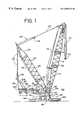
- FIG. 1shows a right side view of an embodiment of a crawler crane according to the present invention
- FIG. 2shows a right side view of a second embodiment of a crawler crane according to the present invention
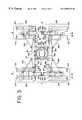
- FIG. 3shows a top view of a carbody and crawler assembly system to be used with the crawler cranes of FIGS. 1-2;
- FIG. 4Ashows a top view of a crawler assembly to be used with the crawler cranes of FIGS. 1-3 and 13 - 14 ;
- FIG. 4Bshows a left side view of the crawler assembly of FIG. 4B
- FIG. 4Cshows a right side view of a crawler frame to be used with the crawler assembly of FIGS. 4A-B;
- FIG. 4Dshows a top view of the crawler frame of FIG. 4C
- FIG. 4Eshows a front view of the crawler frame of FIG. 4C
- FIG. 5Ashows a top view of a beam of a carbody to be used with the crawler cranes of FIGS. 1-3 and 13 - 14 ;
- FIG. 5Bshows a side view of the carbody to be used with the crawler cranes of FIGS. 1-3 and 13 - 14 ;
- FIG. 5Cshows a top view of the connection between the central support structure and the beam of the carbody of FIGS. 5A-B;
- FIG. 5Dshows a sectional view of the connection of FIG. 5C taken along line A—A of FIG. 5C;
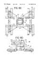
- FIG. 6Ashows a front view of the connection between the crawler assembly of FIGS. 4A-E and the carbody of FIGS. 5A-B;
- FIG. 6Bshows a front view of a carbody to crawler assembly connector to be used with the connection of FIG. 6A;
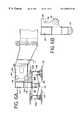
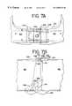
- FIG. 7Ashows a top view of the connection between two aligned crawler assemblies used with the crawler cranes of FIGS. 1-3 and 13 - 14 ;
- FIG. 7Bshows a side cross-sectional view of the connection of FIG. 7A taken along line B—B of FIG. 7A;
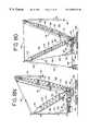
- FIGS. 8A-Oshow the progressive assembly of the crawler crane of FIG. 1;
- FIG. 9Ashows a side view of a hoist drum support to be used with the crawler cranes of FIGS. 1-2 and 13 - 14 ;
- FIG. 9Bshows a front view of a support plate to be used with the support of FIG. 9A;
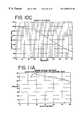
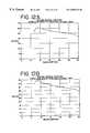
- FIG. 10Ashows a lift capacity v. load radius graph when a crawler crane embodying the present invention uses a 45.7 m superstructure
- FIG. 10Bshows a lift capacity v. load radius graph when a crawler crane embodying the present invention uses a 68.6 m superstructure
- FIG. 10Cshows a lift capacity vs. load radius graph when a crawler crane embodying the present invention uses a 91.4 m superstructure
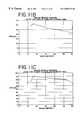
- FIG. 11Ashows a ground bearing pressure over the front of the crawler vs. load radius graph for 1.2 m wide crawler track
- FIG. 11Bshows a ground bearing pressure over the side of the crawler vs. load radius graph for 1.2 m wide crawler track
- FIG. 11Cshows a ground bearing pressure over the corner of the crawler vs. load radius graph for 1.2 m wide crawler track
- FIG. 12Ashows a ground bearing pressure over the front of the crawler vs. toad radius graph for 1.5 m wide crawler track;
- FIG. 12Bshows a ground bearing pressure over the side of the crawler vs. load radius graph for 1.5 m wide crawler track
- FIG. 12Cshows a ground bearing pressure over the corner of the crawler vs. load radius graph for 1.5 m wide crawler track
- FIG. 13shows a top view of a second embodiment of a carbody and crawler assembly system according to the present invention.
- FIG. 14shows a top view of a third embodiment of a carbody and crawler assembly system according to the present invention.
- the preferred embodiment of the present inventionrelates to a four track crawler crane, other aspects of which are disclosed in U.S. Pat. Nos. 5,148,929; 5,189,605; 5,199,586; 5,292,016; 5,297,019; 5,427,256; 5,579,931; 5,649,635 and copending U.S. patent application Ser. No. 08/826,627, filed Apr. 3, 1997 that are assigned to the assignee of the present application and the entire contents of the above mentioned U.S. patents and application are hereby incorporated herein by reference.
- FIG. 1shows a 640 ton crawler crane 100 that basically has five main components: (1) a crane boom 102 ; (2) a mast 104 ; (3) a superstructure 105 that includes and operator's cab 106 ; (4) four sets of crawler assemblies 162 , 164 , 166 , 168 ; and (5) a carbody 110 .
- the 45 ton crane boom 102is connected to the one end of the superstructure 105 and extends into the air above the operator's cab structure.
- the crane boom 102is made of three frames 112 made of high strength steel that are attached to one another in a well known manner so as that the crane boom 102 has a total length of approximately 125 feet.
- the crane boom 102also includes a wire rope system 118 that includes a hook block 120 attached to one end thereof enabling the lifting of an object (not shown) from the ground into the air.
- the mast 104is attached to the superstructure 105 in a manner similar to the attachment of the crane boom 102 to the superstructure 105 .
- the mast 104weighs approximately 36 tons and is composed of three frames 122 made of high strength steel that are attached to one another so as to have a total length of approximately 80 feet.
- the length of the mast 104along with the overall size of the crawler crane 100 , is one of the factors that allows the crawler crane 100 to lift greater loads for a given load radius when compared with existing crawler cranes that can lift over 100 metric tons.
- the lift capacity of the present invention for various booms and load sizesis shown in FIGS. 10A-C. As shown in FIG.
- the second counterweight 142When in use, the second counterweight 142 has a weight that can range up to 500 metric tons so as to provide better stability to the crawler crane 100 by being attached to both the top of the mast 104 and the other counterweight 136 via straps 144 that are similar to straps 128 and a compression frame 146 so as to be approximately 72 feet from the rotation axis 139 .
- the modified crawler crane 100 of FIG. 2has a total weight of approximately 1200 tons.
- Each insertion piece 167has a lower opening 173 and pair of pins 169 that are located on the parallel lateral sides 171 of the insertion piece 167 .
- the pins 169engage the bottom of the openings of the hooks 163 and the beam 150 pivots about the pins 169 until it reaches the position shown in FIG. 5D where the openings 165 and 173 are aligned with each other.
- a pair of pinsare inserted into the aligned openings 165 and 173 so as to attach the beam 150 to the central support structure 148 .
- the opening 226 and the pin 232have a cooperating shape that ensures that the pin 232 will extend through the opening 226 when the front crawler assembly 162 is positioned above the rear crawler assembly 164 at a range of angles from 0 to 45 degrees or 0 to 15 degrees, preferably 5 to 15 degrees, from an operational position where the crawler assemblies 162 and 164 are aligned with each other, as shown in FIGS. 3 and 7 A-B.
- the female receiving member and the male attachment devicemay be interchanged without departing from the spirit of the invention.
- the opening 226may be circular or a plurality of pins 232 and openings 226 may be used to attach the crawler assemblies.
- Each crawler frame 206supports an outer loop-like crawler track 210 and an inner loop-like crawler track 212 that have a width of approximately 1.22 m and a length of approximately 5.06 m.
- the outer and inner track widthsmay be 1.52 m as well.
- the outer and inner tracks 210 and 212are separated from one another by a distance of approximately 90.5′′.
- each crawler assembly 162 , 164 , 166 , 168is composed of an outer crawler track 210 and an inner crawler track 212 that are parallel to each other and are located on opposing lateral sides 214 , 216 of the central frame 204 .
- each crawler frame 206 of the crawler assembly 162has a tumbler 218 at the inner end that engages and moves the crawler tracks 210 , 212 associated with the crawler frame 206 in a well known manner.
- the tumbler 218 associated with each crawler frame 206is driven by a hydraulic motor and gear reduction in a well known manner.
- the outer crawler track 210is powered by at least one motor and gear reduction 220 and the inner crawler track 212 is powered by at least one motor and gear reduction 222 as shown in FIG. 3 .
- the motors 220 and 222 associated with each crawler frame 206are controlled by an operator in the operator's cab 106 in a well known manner.
- the motors 220 and 222are synchronized so that each of the crawler tracks 210 and 212 of the crawler assembly 162 move in unison. Synchronization is achieved by having the motors 220 and 222 share a common pump that supplies the hydraulic fluid to the motors.
- the inner and outer crawler tracks 210 and 212 of the front crawler assembly 166 located on the right side R of the carbody 110are aligned with the direction of travel of the inner and outer crawler tracks 210 and 212 , respectively, of the rear crawler assembly 168 . It is desired that the aligned front and rear crawler assemblies 162 and 164 on the left side of the carbody 110 act as a single left crawler track and the aligned crawler assemblies 166 and 168 on the right side of the carbody 110 act as a single right crawler track.
- the crane boom 102 and the mast 104can be attached.
- the top and bottom frames 122 of the mast 104 , the boom hoist drum 127 and the equalizerare transported on one trailer bed and the middle frame 122 of the mast 104 is transported on a separate trailer bed.
- the top and bottom frames 122 of the mast 104are attached to one another.
- the boom hoist drum 127is rotatably attached within the bottom frame of the mast 104 by having a support plate 155 that is attached to a pair of brackets 157 , 159 that are attached to the bottom frame as schematically shown in FIGS. 9A-B.
- the top and bottom frames 122are attached to the adapter frame 149 in a well known manner.
- the top and bottom frames 122are separated from one another so that the middle frame 122 is placed between and attached to the top and bottom masts 122 (see FIG. 8 H).
- the wire rope system 306is pulled from the hoist drum 308 and connected to the equalizer 130 .
- the hoist drum 308is then rotated so as to hoist the mast 104 upwards (see FIG. 8 J).
- the completed mast 104 of FIG. 8Jis used to hoist and support the crane boom 102 on the crawler crane 100 .
- the three frames 112 of the crane boom 102are attached to one another in a well known manner adjacent to the crawler crane 100 .
- the three frames 112are transported to the work site on separate trailer beds.
- the second operator's wire rope system 126is arranged to have the equalizer 129 engage the bottom of the crane boom 102 while the top end of the crane boom 102 is lifted by an auxiliary crane.
- the crane boom 102is then attached to the adapter frame 149 in a well known manner.
- the overall width of attached carbody 110 and the crawler assemblies 162 , 164 , 166 and 168can be reduced to about 30 feet by removing the beams 150 and 152 and attaching the crawler assemblies directly to the four attachment extensions or beams 159 of the central support structure 148 (see FIG. 13 ).
- Each crawler assembly 162 , 164 , 166 , 168has an attachment piece 312 that has a structure and function similar to the male insertion pieces 167 described previously that has a pair of pins and a lowering opening.
- the crawler assembliesare lowered onto the beams 159 so that their pins engage the hooks 163 and pivot downwards into an operational position where the crawler assemblies are locked in place by pins inserted into the lower openings.
- the net effect of this attachmentis a narrower crawler crane 100 and the direction of movement of the crawler assemblies is parallel to the front and rear sides 156 and 158 of the central support structure 148 .
- triangular-like out riggers 314can be attached to the assembled crawler assemblies so as to provide further stability. Note that in this embodiment all components of the crawler crane 100 and all assembling steps are the same as described previously for the crawler crane 100 of FIG. 1 unless specified otherwise above.
- FIG. 13can be transformed into a 47 foot wide crawler crane 100 by attaching beams 316 and 318 to the carbody.
- Beams 316 and 318has the same attachment structure for attachment to the central support structure 148 as beams 150 and 152 for the embodiment of FIG. 1 .
- the end of the beams 316 and 318are adapted to face the attachment pieces 312 and the ends of the beams 316 and 318 have a hook-like structure similar to that of the ends of the beams 150 and 152 . Accordingly, attachment of the assembled crawler assemblies to the beams 316 and 318 is similar to the attachment of the crawler assemblies and beams 150 and 152 of FIG. 1 .
Landscapes
- Engineering & Computer Science (AREA)
- Mechanical Engineering (AREA)
- Mining & Mineral Resources (AREA)
- Civil Engineering (AREA)
- General Engineering & Computer Science (AREA)
- Structural Engineering (AREA)
- Jib Cranes (AREA)
Abstract
Description
Claims (20)
Priority Applications (1)
| Application Number | Priority Date | Filing Date | Title |
|---|---|---|---|
| US09/277,364US6588521B1 (en) | 1998-03-27 | 1999-03-26 | Four track crawler crane |
Applications Claiming Priority (2)
| Application Number | Priority Date | Filing Date | Title |
|---|---|---|---|
| US7972798P | 1998-03-27 | 1998-03-27 | |
| US09/277,364US6588521B1 (en) | 1998-03-27 | 1999-03-26 | Four track crawler crane |
Publications (2)
| Publication Number | Publication Date |
|---|---|
| US6588521B1true US6588521B1 (en) | 2003-07-08 |
| US20030127257A1 US20030127257A1 (en) | 2003-07-10 |
Family
ID=22152413
Family Applications (1)
| Application Number | Title | Priority Date | Filing Date |
|---|---|---|---|
| US09/277,364Expired - LifetimeUS6588521B1 (en) | 1998-03-27 | 1999-03-26 | Four track crawler crane |
Country Status (5)
| Country | Link |
|---|---|
| US (1) | US6588521B1 (en) |
| EP (1) | EP0945393B1 (en) |
| JP (2) | JP4460674B2 (en) |
| CA (1) | CA2266791C (en) |
| DE (1) | DE69927865T2 (en) |
Cited By (26)
| Publication number | Priority date | Publication date | Assignee | Title |
|---|---|---|---|---|
| US20030196839A1 (en)* | 2002-04-19 | 2003-10-23 | Moore Donald E. | Systems for connecting a ground-engaging motive device to a vehicle and related methods |
| US20040107607A1 (en)* | 2002-12-06 | 2004-06-10 | Komatsu Ltd. | Crawler frame for construction machine |
| US20040124166A1 (en)* | 2002-12-12 | 2004-07-01 | Hans-Dieter Willim | Mobile crane substructure |
| US20040177533A1 (en)* | 2003-03-10 | 2004-09-16 | Komatsu Ltd. | Crawler frame for construction machine |
| US20050204590A1 (en)* | 2004-03-22 | 2005-09-22 | Yoshiyuki Takano | Construction machine |
| WO2007056969A1 (en)* | 2005-11-17 | 2007-05-24 | Terex-Demag Gmbh & Co. Kg | Large mobile crane |
| US20080264887A1 (en)* | 2007-04-26 | 2008-10-30 | Porubcansky Kenneth J | Mast raising structure and process for high-capacity mobile lift crane |
| US20100072155A1 (en)* | 2008-09-22 | 2010-03-25 | Foust Bronson E | Carbody Connection System and Crane Using Same |
| US20100072158A1 (en)* | 2008-09-19 | 2010-03-25 | Wanek Michael J | Drum Frame System For Cranes |
| US20100108632A1 (en)* | 2003-03-11 | 2010-05-06 | Volvo Construction Equipment Ab | Pipelayer Crane Excavator Apparatus and Methods |
| US20100320166A1 (en)* | 2005-09-28 | 2010-12-23 | Terex-Demag Gmbh | Crane, in particular mobile crane with a narrow track and enlarged supporting base |
| US20110031202A1 (en)* | 2009-08-06 | 2011-02-10 | Pech David J | Lift crane with moveable counterweight |
| WO2011075969A1 (en)* | 2009-12-24 | 2011-06-30 | 三一电气有限责任公司 | Amphibious crawler crane |
| US20130079974A1 (en)* | 2011-09-23 | 2013-03-28 | Manitowoc Crane Companies, Llc | Outrigger monitoring system and methods |
| US20140069883A1 (en)* | 2012-09-12 | 2014-03-13 | A2Sea A/S | System for rearranging the counterweight of a crane operation |
| US8985353B2 (en) | 2006-10-27 | 2015-03-24 | Manitowoc Crane Companies, Llc | Mobile lift crane with variable position counterweight |
| US9051159B2 (en) | 2012-12-20 | 2015-06-09 | Manitowoc Crane Companies, Llc | Column connector system |
| US9187296B2 (en) | 2007-11-29 | 2015-11-17 | Manitowoc Crane Companies, Llc | Connection system for crane column segments |
| US20180029852A1 (en)* | 2016-07-29 | 2018-02-01 | Liebherr-Werk Nenzing Gmbh | Mobile machine |
| US20180140877A1 (en)* | 2011-07-20 | 2018-05-24 | Flaresun Fire Group, Inc. | Victim retrieval system, method and appratus |
| US10179722B2 (en) | 2014-01-27 | 2019-01-15 | Manitowoc Crane Companies, Llc | Lift crane with improved movable counterweight |
| US10183848B2 (en) | 2014-01-27 | 2019-01-22 | Manitowoc Crane Companies, Llc | Height adjustment mechanism for an auxiliary member on a crane |
| CN109835826A (en)* | 2019-04-18 | 2019-06-04 | 四川川交路桥有限责任公司 | A kind of self-crawling type heavy lift machine |
| US20220297983A1 (en)* | 2021-03-19 | 2022-09-22 | Liebherr-Werk Nenzing Gmbh | Mobile crane comprising a device for facilitating or fully automatically carrying out a raising and/or setting-down process of a derrick boom, and corresponding method |
| CN116194359A (en)* | 2020-07-01 | 2023-05-30 | 汤姆·希尔曼 | Removable Universal Lateral Track Extension System |
| US20230202809A1 (en)* | 2020-03-13 | 2023-06-29 | Xuzhou Construction Machinery Group Co., Ltd. | Crane |
Families Citing this family (19)
| Publication number | Priority date | Publication date | Assignee | Title |
|---|---|---|---|---|
| DE102005021859B4 (en)* | 2005-05-11 | 2007-03-29 | Terex-Demag Gmbh & Co. Kg | Lattice boom crane for lifting heavy loads |
| KR100600337B1 (en)* | 2005-05-26 | 2006-07-18 | 동일고무벨트주식회사 | Undercarriage with shock absorption |
| KR100795667B1 (en) | 2006-10-17 | 2008-01-21 | 한국해양연구원 | A caterpillar vehicle |
| US7546928B2 (en)* | 2006-10-27 | 2009-06-16 | Manitowoc Crane Companies, Inc. | Mobile lift crane with variable position counterweight |
| EP2165963B1 (en)* | 2008-09-22 | 2019-06-12 | Manitowoc Crane Companies, LLC | Trunnion transportation system and crane using same |
| DE202008016876U1 (en)* | 2008-12-19 | 2010-09-23 | Liebherr-Werk Ehingen Gmbh | rotary joint |
| CN102530746B (en)* | 2010-12-07 | 2014-07-23 | 徐工集团工程机械股份有限公司建设机械分公司 | Crane and superlift counterweight device |
| CN201952140U (en)* | 2011-01-19 | 2011-08-31 | 上海三一科技有限公司 | Movable rear counterweight device of crawler crane |
| CN102359119A (en)* | 2011-09-13 | 2012-02-22 | 三一电气有限责任公司 | Mounting method of intertidal wind turbine generator set |
| JP6645222B2 (en)* | 2016-02-03 | 2020-02-14 | コベルコ建機株式会社 | How to attach a crane jib |
| JP6658020B2 (en)* | 2016-02-03 | 2020-03-04 | コベルコ建機株式会社 | Crane and crane assembling method |
| JP6787033B2 (en)* | 2016-10-19 | 2020-11-18 | コベルコ建機株式会社 | How to tilt the mast backwards when assembling the crane |
| CN110422773A (en)* | 2019-08-06 | 2019-11-08 | 海洋石油工程(青岛)有限公司 | Crawler crane exempts to tear the lower dock technique of spelling open |
| CN111535391A (en)* | 2020-05-19 | 2020-08-14 | 山河智能装备股份有限公司 | Large machine with quick assembling and disassembling mechanism for getting on and off vehicle and assembling and disassembling method |
| JP7632094B2 (en) | 2021-06-08 | 2025-02-19 | コベルコ建機株式会社 | Crawler Crane |
| WO2022259673A1 (en)* | 2021-06-08 | 2022-12-15 | コベルコ建機株式会社 | Mobile crane lower traveling body |
| JP7593241B2 (en) | 2021-06-08 | 2024-12-03 | コベルコ建機株式会社 | Mobile crane undercarriage |
| WO2022259672A1 (en)* | 2021-06-08 | 2022-12-15 | コベルコ建機株式会社 | Lower carriage of mobile crane and mobile crane equipped therewith |
| JP7593240B2 (en) | 2021-06-08 | 2024-12-03 | コベルコ建機株式会社 | Mobile crane undercarriage |
Citations (38)
| Publication number | Priority date | Publication date | Assignee | Title |
|---|---|---|---|---|
| DE479760C (en) | 1928-01-27 | 1929-07-22 | Luebecker Maschb Ges | In three points on the chassis of motor vehicles supported frame for conveyor devices u. like |
| US1804816A (en)* | 1925-02-13 | 1931-05-12 | Marion Steam Shovel Co | Crawling traction mechanism |
| US2296659A (en)* | 1940-12-28 | 1942-09-22 | Shell Dev | Method and equipment for moving drilling rigs |
| DE1111037B (en) | 1959-10-09 | 1961-07-13 | Buckau Wolf Maschf R | Steerable caterpillar vehicle with four track units assigned to the support points of the chassis frame |
| US3036650A (en) | 1959-08-03 | 1962-05-29 | Thew Shovel Co | Carrier with demountable side frames |
| US3166138A (en)* | 1961-10-26 | 1965-01-19 | Jr Edward D Dunn | Stair climbing conveyance |
| US3638805A (en) | 1968-09-19 | 1972-02-01 | Potain Chevilly Larue Val De M | Mobile chassis for carrying a tower crane |
| US3696879A (en)* | 1969-05-31 | 1972-10-10 | Komatsu Mfg Co Ltd | Heavy bulldozer |
| US3820616A (en)* | 1972-02-03 | 1974-06-28 | American Hoist & Derrick Co | Crawler vehicle with dual extensible side frames |
| US3946822A (en)* | 1973-12-21 | 1976-03-30 | O & K Orenstein & Koppel Aktiengesellschaft | Tracklaying vehicle comprising four tracklaying units |
| DE2517203A1 (en) | 1975-04-18 | 1976-10-21 | Liebherr Werk Ehingen | Slewing and derricking mobile crane - has outrigger beams on crawler tracks fitted in star pattern for lifting |
| US3998286A (en)* | 1975-11-19 | 1976-12-21 | Caterpillar Tractor Co. | Mechanically, laterally adjustable treads for crawler vehicles |
| US4000784A (en) | 1975-04-24 | 1977-01-04 | The Manitowoc Company, Inc. | Demountable self-propelled crane transport assembly |
| US4171023A (en)* | 1978-04-28 | 1979-10-16 | Caterpillar Tractor Co. | Triple tractor assembly |
| US4174757A (en)* | 1977-10-03 | 1979-11-20 | Caterpillar Tractor Co. | Material ripping vehicle |
| US4231699A (en) | 1979-01-24 | 1980-11-04 | Dresser Industries, Inc. | Lower and crawler frame construction for crawler propelled machines |
| GB2053146A (en) | 1979-07-17 | 1981-02-04 | Manitowoc Co | Movable ring supported lift crane |
| US4266679A (en) | 1979-04-09 | 1981-05-12 | Harnischfeger Corporation | Convertible boom machine having modular bottom portion |
| DE2949279A1 (en) | 1979-12-07 | 1981-06-11 | M.A.N. Maschinenfabrik Augsburg-Nürnberg AG, 8500 Nürnberg | Multiple tracked large earthmoving machine - has steering mechanism with bolt from one steering bar sliding in ring forming part of hinge bearing |
| US4324304A (en) | 1979-09-05 | 1982-04-13 | Mitsubishi Jukogyo Kabushiki Kaisha | Crawler-type lower machinery |
| US4387814A (en)* | 1981-09-08 | 1983-06-14 | The Manitowoc Company, Inc. | Traveling attachment for ring supported lift crane |
| US4431074A (en) | 1982-01-25 | 1984-02-14 | Fmc Corporation | Crane carbody and lower axle construction |
| US4445582A (en)* | 1981-02-17 | 1984-05-01 | Skega Ab | Track unit of bogie type |
| US4579182A (en)* | 1983-02-28 | 1986-04-01 | Mckay International Engineers | Steerable, track-type vehicle for bulky loads |
| US4625820A (en) | 1985-04-09 | 1986-12-02 | Kidde, Inc. | Crawler frame to base frame connection |
| US4645023A (en)* | 1984-03-05 | 1987-02-24 | Watercraft Offshore Canada Ltd. | All terrain vehicle and method of operating same |
| US5113958A (en)* | 1990-05-23 | 1992-05-19 | Holden Thomas R | Snow travel vehicle |
| US5148929A (en) | 1991-09-20 | 1992-09-22 | The Manitowoc Company Inc. | Multi-coupling device for crane hydraulic lines |
| US5189605A (en) | 1989-10-10 | 1993-02-23 | The Manitowoc Company, Inc. | Control and hydraulic system for a liftcrane |
| US5199586A (en) | 1991-07-25 | 1993-04-06 | The Manitowoc Company, Inc. | Quick-connect sectional boom members for cranes and the like |
| US5292016A (en) | 1992-10-08 | 1994-03-08 | The Manitowoc Company | Luffing jib backstop assembly |
| US5297019A (en) | 1989-10-10 | 1994-03-22 | The Manitowoc Company, Inc. | Control and hydraulic system for liftcrane |
| US5427256A (en) | 1991-09-20 | 1995-06-27 | The Manitowoc Company, Inc. | Crane upper works to lower works alignment system |
| US5435405A (en)* | 1993-05-14 | 1995-07-25 | Carnegie Mellon University | Reconfigurable mobile vehicle with magnetic tracks |
| US5579931A (en) | 1989-10-10 | 1996-12-03 | Manitowoc Engineering Company | Liftcrane with synchronous rope operation |
| US5649635A (en) | 1991-09-20 | 1997-07-22 | Manitowac Crane Group, Inc. | Easily removable sheave assembly |
| US5823279A (en) | 1991-09-20 | 1998-10-20 | Hanitowoc Crane Group, Inc. | Carbody to crawler connection |
| US6010018A (en) | 1997-04-03 | 2000-01-04 | Manitowoc Crane Group, Inc. | Swing lock mechanism |
Family Cites Families (6)
| Publication number | Priority date | Publication date | Assignee | Title |
|---|---|---|---|---|
| JPS60105281A (en)* | 1983-11-11 | 1985-06-10 | Fujitsu Ltd | Semiconductor photodetector |
| JPS626877A (en)* | 1985-07-02 | 1987-01-13 | Agency Of Ind Science & Technol | Flexible crawler |
| JPH0656057A (en)* | 1991-04-16 | 1994-03-01 | Sumitomo Heavy Ind Ltd | Crawler type vehicle concurrently having also outrigger function |
| JP2728203B2 (en)* | 1996-03-25 | 1998-03-18 | 林野庁森林総合研究所長 | Omni-directional mobile vehicle traveling on uneven terrain and turning method of leg device |
| JPH09263273A (en)* | 1996-03-28 | 1997-10-07 | Nikon Corp | Traveling device |
| JPH1029571A (en)* | 1996-07-15 | 1998-02-03 | Komatsu Ltd | Travel vehicle |
- 1999
- 1999-03-25CACA002266791Apatent/CA2266791C/ennot_activeExpired - Fee Related
- 1999-03-26USUS09/277,364patent/US6588521B1/ennot_activeExpired - Lifetime
- 1999-03-29DEDE69927865Tpatent/DE69927865T2/ennot_activeExpired - Lifetime
- 1999-03-29JPJP12622299Apatent/JP4460674B2/ennot_activeExpired - Fee Related
- 1999-03-29EPEP99302402Apatent/EP0945393B1/ennot_activeExpired - Lifetime
- 2009
- 2009-09-16JPJP2009215027Apatent/JP4881414B2/ennot_activeExpired - Lifetime
Patent Citations (38)
| Publication number | Priority date | Publication date | Assignee | Title |
|---|---|---|---|---|
| US1804816A (en)* | 1925-02-13 | 1931-05-12 | Marion Steam Shovel Co | Crawling traction mechanism |
| DE479760C (en) | 1928-01-27 | 1929-07-22 | Luebecker Maschb Ges | In three points on the chassis of motor vehicles supported frame for conveyor devices u. like |
| US2296659A (en)* | 1940-12-28 | 1942-09-22 | Shell Dev | Method and equipment for moving drilling rigs |
| US3036650A (en) | 1959-08-03 | 1962-05-29 | Thew Shovel Co | Carrier with demountable side frames |
| DE1111037B (en) | 1959-10-09 | 1961-07-13 | Buckau Wolf Maschf R | Steerable caterpillar vehicle with four track units assigned to the support points of the chassis frame |
| US3166138A (en)* | 1961-10-26 | 1965-01-19 | Jr Edward D Dunn | Stair climbing conveyance |
| US3638805A (en) | 1968-09-19 | 1972-02-01 | Potain Chevilly Larue Val De M | Mobile chassis for carrying a tower crane |
| US3696879A (en)* | 1969-05-31 | 1972-10-10 | Komatsu Mfg Co Ltd | Heavy bulldozer |
| US3820616A (en)* | 1972-02-03 | 1974-06-28 | American Hoist & Derrick Co | Crawler vehicle with dual extensible side frames |
| US3946822A (en)* | 1973-12-21 | 1976-03-30 | O & K Orenstein & Koppel Aktiengesellschaft | Tracklaying vehicle comprising four tracklaying units |
| DE2517203A1 (en) | 1975-04-18 | 1976-10-21 | Liebherr Werk Ehingen | Slewing and derricking mobile crane - has outrigger beams on crawler tracks fitted in star pattern for lifting |
| US4000784A (en) | 1975-04-24 | 1977-01-04 | The Manitowoc Company, Inc. | Demountable self-propelled crane transport assembly |
| US3998286A (en)* | 1975-11-19 | 1976-12-21 | Caterpillar Tractor Co. | Mechanically, laterally adjustable treads for crawler vehicles |
| US4174757A (en)* | 1977-10-03 | 1979-11-20 | Caterpillar Tractor Co. | Material ripping vehicle |
| US4171023A (en)* | 1978-04-28 | 1979-10-16 | Caterpillar Tractor Co. | Triple tractor assembly |
| US4231699A (en) | 1979-01-24 | 1980-11-04 | Dresser Industries, Inc. | Lower and crawler frame construction for crawler propelled machines |
| US4266679A (en) | 1979-04-09 | 1981-05-12 | Harnischfeger Corporation | Convertible boom machine having modular bottom portion |
| GB2053146A (en) | 1979-07-17 | 1981-02-04 | Manitowoc Co | Movable ring supported lift crane |
| US4324304A (en) | 1979-09-05 | 1982-04-13 | Mitsubishi Jukogyo Kabushiki Kaisha | Crawler-type lower machinery |
| DE2949279A1 (en) | 1979-12-07 | 1981-06-11 | M.A.N. Maschinenfabrik Augsburg-Nürnberg AG, 8500 Nürnberg | Multiple tracked large earthmoving machine - has steering mechanism with bolt from one steering bar sliding in ring forming part of hinge bearing |
| US4445582A (en)* | 1981-02-17 | 1984-05-01 | Skega Ab | Track unit of bogie type |
| US4387814A (en)* | 1981-09-08 | 1983-06-14 | The Manitowoc Company, Inc. | Traveling attachment for ring supported lift crane |
| US4431074A (en) | 1982-01-25 | 1984-02-14 | Fmc Corporation | Crane carbody and lower axle construction |
| US4579182A (en)* | 1983-02-28 | 1986-04-01 | Mckay International Engineers | Steerable, track-type vehicle for bulky loads |
| US4645023A (en)* | 1984-03-05 | 1987-02-24 | Watercraft Offshore Canada Ltd. | All terrain vehicle and method of operating same |
| US4625820A (en) | 1985-04-09 | 1986-12-02 | Kidde, Inc. | Crawler frame to base frame connection |
| US5189605A (en) | 1989-10-10 | 1993-02-23 | The Manitowoc Company, Inc. | Control and hydraulic system for a liftcrane |
| US5297019A (en) | 1989-10-10 | 1994-03-22 | The Manitowoc Company, Inc. | Control and hydraulic system for liftcrane |
| US5579931A (en) | 1989-10-10 | 1996-12-03 | Manitowoc Engineering Company | Liftcrane with synchronous rope operation |
| US5113958A (en)* | 1990-05-23 | 1992-05-19 | Holden Thomas R | Snow travel vehicle |
| US5199586A (en) | 1991-07-25 | 1993-04-06 | The Manitowoc Company, Inc. | Quick-connect sectional boom members for cranes and the like |
| US5148929A (en) | 1991-09-20 | 1992-09-22 | The Manitowoc Company Inc. | Multi-coupling device for crane hydraulic lines |
| US5427256A (en) | 1991-09-20 | 1995-06-27 | The Manitowoc Company, Inc. | Crane upper works to lower works alignment system |
| US5649635A (en) | 1991-09-20 | 1997-07-22 | Manitowac Crane Group, Inc. | Easily removable sheave assembly |
| US5823279A (en) | 1991-09-20 | 1998-10-20 | Hanitowoc Crane Group, Inc. | Carbody to crawler connection |
| US5292016A (en) | 1992-10-08 | 1994-03-08 | The Manitowoc Company | Luffing jib backstop assembly |
| US5435405A (en)* | 1993-05-14 | 1995-07-25 | Carnegie Mellon University | Reconfigurable mobile vehicle with magnetic tracks |
| US6010018A (en) | 1997-04-03 | 2000-01-04 | Manitowoc Crane Group, Inc. | Swing lock mechanism |
Non-Patent Citations (4)
| Title |
|---|
| "Demag CC 2600 Brochure," published by Mannesmann Demag Fordertechnik, pp. 1-10. While the date of publication is unknown, it is believed that the Brochure was published prior to Mar. 27, 1998. |
| "Demag CC 4800 Brochure," published by Mannesmann Demag, pp. 1-10. While the date of publication is unknown, it is believed that the Brochure was published prior to Mar. 27, 1998. |
| "Liebherr LR 1550 Brochure," published by Liebherr, 8 pages. While the date of publication is unknown, it is believed that the Brochure was published in 1993. |
| "Liebherr LR 1650 Brochure," published by Liebherr, 8 pages. While the date of publication is unknown, it is believed that the Brochure was published prior to Mar. 27, 1998. |
Cited By (49)
| Publication number | Priority date | Publication date | Assignee | Title |
|---|---|---|---|---|
| US20030196839A1 (en)* | 2002-04-19 | 2003-10-23 | Moore Donald E. | Systems for connecting a ground-engaging motive device to a vehicle and related methods |
| US6848522B2 (en)* | 2002-04-19 | 2005-02-01 | Link-Belt Construction Equipment Co. L.P. , Lllp | Systems for connecting a ground-engaging motive device to a vehicle and related methods |
| US7293374B2 (en)* | 2002-12-06 | 2007-11-13 | Komatsu Ltd. | Crawler frame for construction machine |
| US20040107607A1 (en)* | 2002-12-06 | 2004-06-10 | Komatsu Ltd. | Crawler frame for construction machine |
| US20040124166A1 (en)* | 2002-12-12 | 2004-07-01 | Hans-Dieter Willim | Mobile crane substructure |
| US20040177533A1 (en)* | 2003-03-10 | 2004-09-16 | Komatsu Ltd. | Crawler frame for construction machine |
| US7293375B2 (en)* | 2003-03-10 | 2007-11-13 | Komatsu Ltd. | Crawler frame for construction machine |
| US20100108632A1 (en)* | 2003-03-11 | 2010-05-06 | Volvo Construction Equipment Ab | Pipelayer Crane Excavator Apparatus and Methods |
| US20050204590A1 (en)* | 2004-03-22 | 2005-09-22 | Yoshiyuki Takano | Construction machine |
| US20100320166A1 (en)* | 2005-09-28 | 2010-12-23 | Terex-Demag Gmbh | Crane, in particular mobile crane with a narrow track and enlarged supporting base |
| US8225947B2 (en)* | 2005-09-28 | 2012-07-24 | Terex Demag Gmbh | Crane, in particular mobile crane with a narrow track and enlarged supporting base |
| WO2007056969A1 (en)* | 2005-11-17 | 2007-05-24 | Terex-Demag Gmbh & Co. Kg | Large mobile crane |
| US20090289495A1 (en)* | 2005-11-17 | 2009-11-26 | Terex-Demag Gmbh & Lg | Large Mobile Crane |
| US10246310B2 (en) | 2005-11-17 | 2019-04-02 | Terex Global Gmbh | Large mobile crane |
| US8727145B2 (en) | 2005-11-17 | 2014-05-20 | Terex Cranes Germany Gmbh | Large mobile crane |
| US10336589B2 (en) | 2006-10-27 | 2019-07-02 | Manitowoc Crane Companies, Llc | Mobile lift crane with variable position counterweight |
| US8985353B2 (en) | 2006-10-27 | 2015-03-24 | Manitowoc Crane Companies, Llc | Mobile lift crane with variable position counterweight |
| US12187587B2 (en) | 2006-10-27 | 2025-01-07 | Grove U.S. L.L.C. | Mobile lift crane with variable position counterweight |
| US11884522B2 (en) | 2006-10-27 | 2024-01-30 | Grove U.S. L.L.C. | Mobile lift crane with variable position counterweight |
| US7762412B2 (en)* | 2007-04-26 | 2010-07-27 | Manitowoc Crane Companies, Llc | Mast raising structure and process for high-capacity mobile lift crane |
| US20080264887A1 (en)* | 2007-04-26 | 2008-10-30 | Porubcansky Kenneth J | Mast raising structure and process for high-capacity mobile lift crane |
| US9187296B2 (en) | 2007-11-29 | 2015-11-17 | Manitowoc Crane Companies, Llc | Connection system for crane column segments |
| US9121425B2 (en) | 2007-11-29 | 2015-09-01 | Manitowoc Crane Companies, Llc | Connection system for crane components |
| US8397924B2 (en)* | 2008-09-19 | 2013-03-19 | Manitowoc Crane Companies, Llc | Drum frame system for cranes |
| US20100072158A1 (en)* | 2008-09-19 | 2010-03-25 | Wanek Michael J | Drum Frame System For Cranes |
| US20100072155A1 (en)* | 2008-09-22 | 2010-03-25 | Foust Bronson E | Carbody Connection System and Crane Using Same |
| US8348073B2 (en)* | 2008-09-22 | 2013-01-08 | Manitowoc Crane Companies, Llc | Carbody connection system and crane using same |
| US11261064B2 (en) | 2009-08-06 | 2022-03-01 | Manitowoc Cranes, Llc | Lift crane with moveable counterweight |
| US20110031202A1 (en)* | 2009-08-06 | 2011-02-10 | Pech David J | Lift crane with moveable counterweight |
| US9278834B2 (en) | 2009-08-06 | 2016-03-08 | Manitowoc Crane Group, LLC | Lift crane with moveable counterweight |
| US10457530B2 (en) | 2009-08-06 | 2019-10-29 | Manitowoc Cranes, Llc | Lift crane with moveable counterweight |
| WO2011075969A1 (en)* | 2009-12-24 | 2011-06-30 | 三一电气有限责任公司 | Amphibious crawler crane |
| US20180140877A1 (en)* | 2011-07-20 | 2018-05-24 | Flaresun Fire Group, Inc. | Victim retrieval system, method and appratus |
| US10806956B2 (en)* | 2011-07-20 | 2020-10-20 | Flaresun Fire Group, Inc. | Victim retrieval system, method and apparatus |
| US20130079974A1 (en)* | 2011-09-23 | 2013-03-28 | Manitowoc Crane Companies, Llc | Outrigger monitoring system and methods |
| US9556007B2 (en)* | 2012-09-12 | 2017-01-31 | Terex Cranes Germany Gmbh | System for rearranging the counterweight of a crane operation |
| US20140069883A1 (en)* | 2012-09-12 | 2014-03-13 | A2Sea A/S | System for rearranging the counterweight of a crane operation |
| US9051159B2 (en) | 2012-12-20 | 2015-06-09 | Manitowoc Crane Companies, Llc | Column connector system |
| US10179722B2 (en) | 2014-01-27 | 2019-01-15 | Manitowoc Crane Companies, Llc | Lift crane with improved movable counterweight |
| US11208303B2 (en) | 2014-01-27 | 2021-12-28 | Manitowoc Crane Companies, Llc | Lift crane with improved movable counterweight |
| US10183848B2 (en) | 2014-01-27 | 2019-01-22 | Manitowoc Crane Companies, Llc | Height adjustment mechanism for an auxiliary member on a crane |
| US10435278B2 (en)* | 2016-07-29 | 2019-10-08 | Liebherr-Werk Nenzing Gmbh | Mobile machine |
| US20180029852A1 (en)* | 2016-07-29 | 2018-02-01 | Liebherr-Werk Nenzing Gmbh | Mobile machine |
| CN109835826A (en)* | 2019-04-18 | 2019-06-04 | 四川川交路桥有限责任公司 | A kind of self-crawling type heavy lift machine |
| CN109835826B (en)* | 2019-04-18 | 2024-01-30 | 四川川交路桥有限责任公司 | Self-climbing type heavy elevator |
| US20230202809A1 (en)* | 2020-03-13 | 2023-06-29 | Xuzhou Construction Machinery Group Co., Ltd. | Crane |
| CN116194359A (en)* | 2020-07-01 | 2023-05-30 | 汤姆·希尔曼 | Removable Universal Lateral Track Extension System |
| US20220297983A1 (en)* | 2021-03-19 | 2022-09-22 | Liebherr-Werk Nenzing Gmbh | Mobile crane comprising a device for facilitating or fully automatically carrying out a raising and/or setting-down process of a derrick boom, and corresponding method |
| US11970372B2 (en)* | 2021-03-19 | 2024-04-30 | Liebherr-Werk Nenzing Gmbh | Mobile crane comprising a device for facilitating or fully automatically carrying out a raising and/or setting-down process of a derrick boom, and corresponding method |
Also Published As
| Publication number | Publication date |
|---|---|
| DE69927865T2 (en) | 2006-07-20 |
| JP4881414B2 (en) | 2012-02-22 |
| JP2000038288A (en) | 2000-02-08 |
| CA2266791A1 (en) | 1999-09-27 |
| EP0945393A3 (en) | 2003-04-23 |
| EP0945393A2 (en) | 1999-09-29 |
| CA2266791C (en) | 2005-02-01 |
| EP0945393B1 (en) | 2005-10-26 |
| JP4460674B2 (en) | 2010-05-12 |
| DE69927865D1 (en) | 2005-12-01 |
| US20030127257A1 (en) | 2003-07-10 |
| JP2009292473A (en) | 2009-12-17 |
Similar Documents
| Publication | Publication Date | Title |
|---|---|---|
| US6588521B1 (en) | Four track crawler crane | |
| US4394911A (en) | Heavy duty crane | |
| CN101549835B (en) | Lattice mast crane and lattice mast boom | |
| US4266679A (en) | Convertible boom machine having modular bottom portion | |
| US5615784A (en) | Crane counterweight installation and removal apparatus | |
| CA2113364C (en) | Transport means for a longitudinally divisible crane boom segment | |
| US3830376A (en) | Telescopic jib and bearing means therefor | |
| US8225947B2 (en) | Crane, in particular mobile crane with a narrow track and enlarged supporting base | |
| KR20090056830A (en) | Connection system for the crane boom segment | |
| US7007764B2 (en) | Carbody to crawler connection | |
| US5921415A (en) | Bridge erection system | |
| US4483448A (en) | Heavy duty crane | |
| CN212895919U (en) | Lifting device of integrated bridge girder erection machine | |
| US20020027118A1 (en) | Vehicle crane | |
| US4609204A (en) | Extension for outrigger beam | |
| EP1673304B1 (en) | A mobile crane | |
| CN114180475A (en) | Tower crane facial make-up structure | |
| CN215101591U (en) | A shield constructs quick-witted hoisting structure for secretly dig construction | |
| JP3124498B2 (en) | Bridge loading and unloading device | |
| CA1085780A (en) | Lift crane support system | |
| CN222781301U (en) | crane | |
| JP4684007B2 (en) | Jacking equipment for construction machinery | |
| CN218595964U (en) | Small-sized hoisting equipment for production and manufacture of large plate girder | |
| CN216808043U (en) | LNG immersed pump overhauling auxiliary device | |
| LU504181B1 (en) | End beam structure for signle and double beam crane |
Legal Events
| Date | Code | Title | Description |
|---|---|---|---|
| AS | Assignment | Owner name:BANKERS TRUST COMPANY, NEW YORK Free format text:GRANT OF SECURITY INTEREST;ASSIGNOR:MANITOWOC CRANE COMPANIES, INC. (FORMERLY MANITOWOC CRANE GROUP, INC.);REEL/FRAME:012043/0757 Effective date:20010508 | |
| AS | Assignment | Owner name:MANITOWOC CRANE COMPANIES, INC., NEVADA Free format text:CHANGE OF NAME;ASSIGNOR:MANITOWOC CRANE GROUP, INC.;REEL/FRAME:013049/0066 Effective date:20010227 | |
| STCF | Information on status: patent grant | Free format text:PATENTED CASE | |
| AS | Assignment | Owner name:MANITOWOC CRANE COMPANIES, INC., NEVADA Free format text:PATENT RELEASE OF SECURITY INTEREST;ASSIGNOR:DEUTSCHE BANK TRUST COMPANY AMERICAS (FOERMERLY KNOWN AS BANKERS TRUST COMPANY), AS AGENT;REEL/FRAME:016397/0347 Effective date:20050610 | |
| AS | Assignment | Owner name:JPMORGAN CHASE BANK, N.A., AS AGENT, ILLINOIS Free format text:GRANT OF SECURITY INTEREST IN U.S. PATENTS;ASSIGNOR:MANITOWOC CRANE COMPANIES, INC.;REEL/FRAME:016446/0054 Effective date:20050610 | |
| FPAY | Fee payment | Year of fee payment:4 | |
| AS | Assignment | Owner name:JPMORGAN CHASE BANK, N.A., AS AGENT, ILLINOIS Free format text:SECURITY AGREEMENT;ASSIGNOR:MANITOWOC CRANE COMPANIES, INC.;REEL/FRAME:022399/0530 Effective date:20080414 Owner name:JPMORGAN CHASE BANK, N.A., AS AGENT,ILLINOIS Free format text:SECURITY AGREEMENT;ASSIGNOR:MANITOWOC CRANE COMPANIES, INC.;REEL/FRAME:022399/0530 Effective date:20080414 | |
| AS | Assignment | Owner name:MANITOWOC CRANE COMPANIES, INC., NEVADA Free format text:RELEASE OF SECURITY INTEREST IN U.S. PATENTS;ASSIGNOR:JPMORGAN CHASE BANK, N.A. AS AGENT;REEL/FRAME:022416/0092 Effective date:20081106 | |
| FPAY | Fee payment | Year of fee payment:8 | |
| AS | Assignment | Owner name:MANITOWOC CRANE COMPANIES, LLC, WISCONSIN Free format text:MERGER;ASSIGNOR:MANITOWOC CRANE COMPANIES, INC.;REEL/FRAME:033990/0564 Effective date:20091231 | |
| FPAY | Fee payment | Year of fee payment:12 | |
| AS | Assignment | Owner name:MANITOWOC CRANE COMPANIES, LLC, WISCONSIN Free format text:RELEASE BY SECURED PARTY;ASSIGNOR:JPMORGAN CHASE BANK, N.A., AS COLLATERAL AGENT;REEL/FRAME:037899/0053 Effective date:20160303 | |
| AS | Assignment | Owner name:WELLS FARGO BANK, NATIONAL ASSOCIATION, AS AGENT, Free format text:SECURITY INTEREST;ASSIGNOR:MANITOWOC CRANE COMPANIES, LLC;REEL/FRAME:038038/0924 Effective date:20160303 | |
| AS | Assignment | Owner name:WELLS FARGO BANK, NATIONAL ASSOCIATION, NEW YORK Free format text:SECURITY INTEREST;ASSIGNOR:MANITOWOC CRANE COMPANIES, LLC;REEL/FRAME:038383/0094 Effective date:20160303 | |
| AS | Assignment | Owner name:MANITOWOC CRANE COMPANIES, LLC, WISCONSIN Free format text:RELEASE BY SECURED PARTY;ASSIGNOR:WELLS FARGO BANK, NATIONAL ASSOCIATION;REEL/FRAME:048694/0456 Effective date:20190325 | |
| AS | Assignment | Owner name:MANITOWOC CRANES, LLC, WISCONSIN Free format text:RELEASE OF SECURITY INTERESTS;ASSIGNOR:WELLS FARGO BANK, NATIONAL ASSOCIATION;REEL/FRAME:048698/0521 Effective date:20190325 Owner name:THE MANITOWOC COMPANY, INC., WISCONSIN Free format text:RELEASE OF SECURITY INTERESTS;ASSIGNOR:WELLS FARGO BANK, NATIONAL ASSOCIATION;REEL/FRAME:048698/0521 Effective date:20190325 Owner name:MANITOWOC CRANE COMPANIES, LLC, WISCONSIN Free format text:RELEASE OF SECURITY INTERESTS;ASSIGNOR:WELLS FARGO BANK, NATIONAL ASSOCIATION;REEL/FRAME:048698/0521 Effective date:20190325 Owner name:GROVE U.S. L.L.C., PENNSYLVANIA Free format text:RELEASE OF SECURITY INTERESTS;ASSIGNOR:WELLS FARGO BANK, NATIONAL ASSOCIATION;REEL/FRAME:048698/0521 Effective date:20190325 |