US6588313B2 - Hydraulic piston position sensor - Google Patents
Hydraulic piston position sensorDownload PDFInfo
- Publication number
- US6588313B2 US6588313B2US09/991,817US99181701AUS6588313B2US 6588313 B2US6588313 B2US 6588313B2US 99181701 AUS99181701 AUS 99181701AUS 6588313 B2US6588313 B2US 6588313B2
- Authority
- US
- United States
- Prior art keywords
- piston
- cylinder
- rod
- sliding member
- conductor
- Prior art date
- Legal status (The legal status is an assumption and is not a legal conclusion. Google has not performed a legal analysis and makes no representation as to the accuracy of the status listed.)
- Expired - Lifetime
Links
- 239000004020conductorSubstances0.000claimsabstractdescription28
- 230000008878couplingEffects0.000claimsdescription8
- 238000010168coupling processMethods0.000claimsdescription8
- 238000005859coupling reactionMethods0.000claimsdescription8
- 230000005540biological transmissionEffects0.000description29
- 238000005259measurementMethods0.000description25
- 238000006073displacement reactionMethods0.000description9
- 230000009977dual effectEffects0.000description9
- 239000000463materialSubstances0.000description8
- 238000000034methodMethods0.000description8
- 238000005516engineering processMethods0.000description6
- 239000012530fluidSubstances0.000description5
- 230000005855radiationEffects0.000description4
- 230000008901benefitEffects0.000description3
- 239000002184metalSubstances0.000description3
- 238000010586diagramMethods0.000description2
- 230000007613environmental effectEffects0.000description2
- 239000011521glassSubstances0.000description2
- 238000009413insulationMethods0.000description2
- 230000002463transducing effectEffects0.000description2
- 230000007704transitionEffects0.000description2
- 238000013519translationMethods0.000description2
- 239000004696Poly ether ether ketoneSubstances0.000description1
- 230000001133accelerationEffects0.000description1
- PNEYBMLMFCGWSK-UHFFFAOYSA-Naluminium oxideInorganic materials[O-2].[O-2].[O-2].[Al+3].[Al+3]PNEYBMLMFCGWSK-UHFFFAOYSA-N0.000description1
- 239000010953base metalSubstances0.000description1
- JUPQTSLXMOCDHR-UHFFFAOYSA-Nbenzene-1,4-diol;bis(4-fluorophenyl)methanoneChemical compoundOC1=CC=C(O)C=C1.C1=CC(F)=CC=C1C(=O)C1=CC=C(F)C=C1JUPQTSLXMOCDHR-UHFFFAOYSA-N0.000description1
- 230000033228biological regulationEffects0.000description1
- 230000015556catabolic processEffects0.000description1
- 230000008859changeEffects0.000description1
- 238000006243chemical reactionMethods0.000description1
- 239000011248coating agentSubstances0.000description1
- 238000000576coating methodMethods0.000description1
- 238000004891communicationMethods0.000description1
- 230000003750conditioning effectEffects0.000description1
- 238000005260corrosionMethods0.000description1
- 230000007797corrosionEffects0.000description1
- 238000006731degradation reactionMethods0.000description1
- 230000000593degrading effectEffects0.000description1
- 239000010720hydraulic oilSubstances0.000description1
- 229930195733hydrocarbonNatural products0.000description1
- 150000002430hydrocarbonsChemical class0.000description1
- 230000007774longtermEffects0.000description1
- 238000000691measurement methodMethods0.000description1
- 230000004048modificationEffects0.000description1
- 238000012986modificationMethods0.000description1
- 239000012811non-conductive materialSubstances0.000description1
- 230000003287optical effectEffects0.000description1
- 229920002530polyetherether ketonePolymers0.000description1
- 238000004886process controlMethods0.000description1
- 238000012545processingMethods0.000description1
- 238000002310reflectometryMethods0.000description1
- 230000004044responseEffects0.000description1
- 239000007787solidSubstances0.000description1
- 230000003068static effectEffects0.000description1
- 238000002366time-of-flight methodMethods0.000description1
- 230000001052transient effectEffects0.000description1
Images


Classifications
- F—MECHANICAL ENGINEERING; LIGHTING; HEATING; WEAPONS; BLASTING
- F15—FLUID-PRESSURE ACTUATORS; HYDRAULICS OR PNEUMATICS IN GENERAL
- F15B—SYSTEMS ACTING BY MEANS OF FLUIDS IN GENERAL; FLUID-PRESSURE ACTUATORS, e.g. SERVOMOTORS; DETAILS OF FLUID-PRESSURE SYSTEMS, NOT OTHERWISE PROVIDED FOR
- F15B15/00—Fluid-actuated devices for displacing a member from one position to another; Gearing associated therewith
- F15B15/20—Other details, e.g. assembly with regulating devices
- F15B15/28—Means for indicating the position, e.g. end of stroke
- F15B15/2815—Position sensing, i.e. means for continuous measurement of position, e.g. LVDT
- F15B15/2869—Position sensing, i.e. means for continuous measurement of position, e.g. LVDT using electromagnetic radiation, e.g. radar or microwaves
Definitions
- the present inventionrelates to hydraulic pistons. More specifically, the present invention relates to position sensors used to sense the relative position between a piston and a hydraulic cylinder.
- Inferred displacement measurementssuch as calculating the translation of a cylinder by integrating a volumetric flow rate into the cylinder over time suffer from several difficulties. First, these devices are incremental and require frequent, manual re-zeroing. Secondly, they tend to be sensitive to environmental effects, such as temperature and density. They require measuring these variables to provide an accurate displacement measurement. Further, integrating flow to determine displacement tends to decrease the accuracy of measurement. This technology also is limited by the dynamic sensing range of the flow measurement. Flows above and below this range are susceptible to very high errors.
- An apparatus to measure relative position of a hydraulic piston in a cylinderincludes a rod extending along the direction of movement of the piston and the rod which is fixedly coupled to one of the piston or cylinder.
- the rodis configured to carry a microwave pulse.
- a sliding memberis slidably coupled to the rod and fixedly coupled to the other of one of the piston or cylinder.
- the sliding memberis configured to cause a partial reflection of the microwave pulse.
- the end of the distal rodalso provides a reflection. Piston position is calculated as a function of reflected microwave pulses from the sliding member and the rod end.
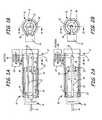
- FIG. 1Ais a side cross-sectional view of a hydraulic assembly including position measurement circuitry.
- FIG. 1Bis a top cross-sectional view taken along the line labeled 1 B— 1 B in FIG. 1 A.
- FIG. 2Ais a side cross-sectional view of a hydraulic assembly including position measurement circuitry.
- FIG. 2Bis a top cross-sectional view taken along the line labeled 2 B— 2 B in FIG. 2 A.
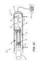
- FIG. 2Cis a partial cutaway perspective view of another embodiment of a hydraulic assembly.
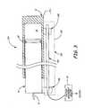
- FIG. 3is a side cross-sectional view of a hydraulic system in which a rod is positioned external to the cylinder.
- FIG. 4is a side cross-sectional view of a hydraulic system in which the piston is used for position measurement.
- FIG. 5is a side cross-sectional view of a coupling.
- FIG. 6shows a hydraulic system including a block diagram of position measurement circuitry.
- FIG. 1Ais a side cross-sectional view and FIG. 1B is a top cross-sectional view of a hydraulic piston/cylinder assembly 10 in accordance with one embodiment of the invention.
- Assembly 10includes cylinder 12 which slidably carries piston 14 therein which is coupled to piston rod 16 .
- Piston 14moves within cylinder 12 in response to hydraulic fluid 18 being applied to or withdrawn from the interior of cylinder 12 through an orifice 19 .
- a seal 20extends around piston 14 to prevent leakage of hydraulic fluid therepast.
- Rods 22extend along the length of cylinder 12 and are coupled to position measurement circuitry 24 .
- Position measurement circuitry 24couples to rods 22 through feedthrough connections 38 .
- An orifice 26is provided in piston 14 such that hydraulic fluid flows into cavity 30 within piston 14 .
- the distal ends 32 of rods 22can be held by a support 34 .
- piston 14slides within cylinder 12 as hydraulic fluid 18 is injected into or removed from cylinder 12 .
- Piston 14also slides along rods 22 which are received in cavity 30 of piston 14 .
- Contacting guide or bushing 40rides along rods 22 as piston 14 moves within cylinder 12 .
- the rods 22are shown fixed to cylinder 12 . They can also be fixed to piston 14 and move relative to cylinder 12 .
- Position measurement circuitry 24provides a position output based upon reflections from microwave signals which are coupled to rods 22 .
- the microwave signalis reflected at two locations on rods 22 : at contacting guide or bushing 40 and at rod ends 32 .
- Position measurement circuitryis responsive to the ratio of the time delay between the two reflected signals to determine the relative position of piston 14 in cylinder 12 .
- the present inventionutilizes Micro Time Domain Reflectometry Radar (MTDR).
- MTDR technologyis a time of flight measurement technology.
- a well-defined impulse or pulsed microwave radar signalis coupled into suitable medium.
- the radar signalis coupled into transmission lines made in the shape of dual parallel conductors. This dual parallel conductor geometry is preferable because it limits radiated electromagnetic interference (EMI).
- EMIradiated electromagnetic interference
- the device responsible for the generation of the radar signal, the coupling of the radar signal into the transmission line, and the sensing of the reflected signalis referred to herein as the transducer.
- the basic MTDR measurementis achieved by sending a radar pulse down a long, slender transmission line such as rods 22 in FIG. 1 and measuring to a high degree of accuracy how long it takes the signal to travel down to a point of reflection and back again.
- This point of reflectioncan be from the distal end 32 of the transmission line, or from a second mechanical body such as support 34 contacting (or adjacent to) the transmission line along its length.
- a mechanical bodysliding member 40
- its positioncan be determined from the transit time of its reflected pulse.
- a reference radar pulsethat is sent to the end 32 of the transmission line formed by rods 22 is generated and timed. This is then compared to the pulse transit time reflected by the sliding mechanical body 40 .
- One advantage of this techniqueis that the measurement is independent of the medium surrounding the transmission line.
- a further advantage of this measurement techniqueis that the frequency of measurement occurs sufficiently rapidly to differentiate the position measurements in time to thereby obtain velocity and acceleration of the piston, if desired.
- angular displacementcan also be measured.
- One embodiment of the inventionincludes the use of a dual element transmission line. This provides two functions. First, it contains radiation to thereby satisfy government regulation. Secondly, in various embodiments the second transmission line can be the cylinder housing itself. This is grounded with respect to the sensing rod, protecting it from spurious changes in dielectric external to the cylinder, such as a coating of mud or other external materials. In a preferred embodiment of the invention, a transient protection scheme is provided to prevent electronics failure in the event of an electrical surge being applied to the cylinder housing.
- Another aspect of the inventionincludes the management of the impedance transitions along the wiring connections between the frequency generation circuitry and the sensing transmission line. Smooth transitions are preferred. Preferably, this is accomplished by gradually changing the spacing between ground and the conductor over a length ⁇ 1 ⁇ 4 wavelength of the pulse. Impedance mismatches that are not gradual appear as ringing (additional pulses) back to the measurement circuit.
- time measured displacementis that the first few inches are typically the most challenging to measure, because the reflected pulse must have a very high “Q” to be distinguishable from the original pulse. Poorly designed impedance mismatches produce a low “Q” reflected signal, resulting in difficulty measuring displacement near the zero position.
- FIG. 2Ais a side cross-sectional view and FIG. 2B is a top cross-sectional view of a hydraulic system 58 in accordance with another embodiment.
- elements similar to those illustrated in FIGS. 1A and 1Bare numbered the same.
- a single rod 60carries two separate conducting rods. This configuration reduces the number of openings which must be provided through piston 14 . Openings 61 allow fluid flow past guide 14 .
- FIG. 2Cis a partial cutaway perspective view of another embodiment of a hydraulic system 70 in accordance with another example embodiment.
- guides 34 and 40slide within piston rod 16 and have openings 61 formed therein.
- Feed through connection 38extends from a base 72 cylinder 12 .
- FIG. 3is a cross-sectional view of a hydraulic system 100 in accordance with another embodiment.
- a rod assembly 102is positioned outside of the cylinder 12 .
- Rod 104is affixed to piston 14 at connection 106 and slides in contacting glide 108 .
- a housing 109can be of a metal to provide shielding and the entire assembly 100 can be coupled to a electrical ground to prevent spurious radiation from the microwave signal generated by position measurement circuitry 24 .
- FIG. 4shows a hydraulic system 120 in accordance with another embodiment. Reflections are generated at the end 123 of piston 14 and end 125 of cylinder 12 . Elements similar to FIGS. 1A and 1B are numbered the same.
- a conductive second antenna member 122is provided which surrounds the cylinder 112 and is connected to electrical ground.
- the cylinder or pistonis coated with a non-conductive material.
- Second antenna member 122can be a sheath or a metal rod depending upon the external environment, and preferably is a corrosion resistant material with a suitable dielectric. Alternatively, the material can be conductive. Second antenna member 122 is coupled to, and moves with, piston 14 . Piston 14 is coupled to position measurement circuitry 24 .
- a signal sourcecan be coupled directly to the base metal of the cylinder and reflections from the end of the cylinder detected.
- the cylinder and pistoncan also be driven with the radar signal in an opposite configuration.
- An external second conductive sheathcan surround the cylinder and/or piston to prevent the system from radiating into the environment.
- FIG. 5is a cross-sectional view of coupling 38 which is coupled to, for example, coaxial cabling 140 .
- Cabling 140connects to a feedthrough 142 which in turn couples to microstrip-line 144 .
- a transmission rod 146extends through a mounting 148 and into the interior of cylinder 12 . The entire assembly is surrounded by feedthrough 150 .
- FIG. 6shows a hydraulic system 180 including a block diagram of position measurement circuitry 24 .
- Position measurement circuitry 24couples to coupling 38 and includes microwave transceiver 182 and computation circuitry 184 .
- Microwave transceiver circuitry 182includes a pulse generator 186 and a pulse receiver 188 that operate in accordance with known techniques. Such techniques are described, for example, in U.S. Pat. No. 5,361,070, issued Nov. 1, 1994; U.S. Pat. No. 5,465,094, issued Nov. 7, 1995; and 5,609,059, issued Mar. 11, 1997, all issued to McEwan.
- computation circuitry 184measures the position of the piston (not shown in FIG.
- computation circuitry 184provides a position output. This can be implemented in a microprocessor or other logic. Additionally, analog circuitry can be configured to provide an output related to position.
- the present inventionuses a ratio between two reflected signals in order to determine piston position.
- One reflected signalcan be transmitted along the “dipstick” rod from the contact point and another signal can be reflected from the end of the rod.
- the ratio between the time of propagation of these two signalscan be used to determine piston position.
- Such a techniquedoes not require separate compensation for dielectric variations in the hydraulic oil.
- a dual element MTDR transmission linecan be provided having a length suitable for measuring the required translation.
- the dual element transmission lineis also desirable because it reduces stray radiation.
- a couplingis provided to couple a transducing element to the dual element transmission line.
- Some type of contacting bodyshould move along the transmission line and provide an impedance mismatch to cause a reflection in the transmission line.
- the transducer and/or signal conditioning electronicscan be sealed from harsh environmental conditions.
- An analog, digital or optical linkcan be provided for communicating the measured displacement to an external device.
- a dual transmission linecan be fabricated from two separate conducting vias. This can be formed, for example, by two rods with or without insulation.
- the rodscan run substantially in parallel along the length of the transmission line.
- the rod or rodscan be fixed to the cylinder and a contact point coupled to the piston can move along the length of the rod.
- the contact pointcan also provide support for the rod or rods. The support can reduce or prevent excessive deflection during high vibration conditions or other stresses.
- a couplingcan be provided to couple to the rod through the cylinder wall.
- the transducing element, signal generator and signal processing electronicscan be mounted in an environmentally protected enclosure on or spaced apart from the cylinder.
- the dual transmission linecan be formed by two conductors embedded in a substantially rigid non-conducting material.
- the conductorscan run substantially parallel to each other along the length of the transmission line.
- the conductorscan be placed in insulation and fabricated in the shape of a single rod.
- the materialsare compatible with long term exposure to hydrocarbons such as those present in a hydraulic cylinder.
- the contact pointcan be made of a material with a dielectric constant different from the material which forms the transmission line and preferably substantially different. Examples of such materials may include alumina contact and/or glass filled PEEK. Any contact point can be provided such as a roller or a blunt body which slides along the transmission line. The contact point can be urged against the transmission line using any appropriate technique including a spring, magnetic device or fluidic device. However, physical contact is not required as the sliding member can merely be adjacent to the transmission line.
- a two-conductor sheath rodis described, additional embodiments are practicable wherein the cylinder itself can be considered one conductor and a solid rod can be used therein. In such embodiments, it is important that the cylinder housing itself be maintained at signal-ground. It is generally preferable for dual conductor embodiments, that one of the conductors be held at signal ground.
- an absolute measurementis provided and re-zeroing of the system is not required.
- the systemis potentially able to measure piston position with an accuracy of less than plus or minus one millimeter.
- the maximum measurement length (span) of the systemcan be adjusted as required and is only limited by power and transmission line geometry.
- the systemis well adapted for harsh environments by using appropriate materials, and providing a good static seal between the transducer and the transmission line.
- the systemrequires relatively low power and can be operated, for example, using two wire 4-20 mA systems which are used in the process control such as, for example, HART® and FieldbusTM communication techniques.
Landscapes
- Engineering & Computer Science (AREA)
- Physics & Mathematics (AREA)
- Toxicology (AREA)
- Electromagnetism (AREA)
- Radar, Positioning & Navigation (AREA)
- Remote Sensing (AREA)
- Health & Medical Sciences (AREA)
- Fluid Mechanics (AREA)
- Mechanical Engineering (AREA)
- General Engineering & Computer Science (AREA)
- Actuator (AREA)
- Measurement Of Length, Angles, Or The Like Using Electric Or Magnetic Means (AREA)
- Radar Systems Or Details Thereof (AREA)
- Length-Measuring Devices Using Wave Or Particle Radiation (AREA)
Abstract
Description
The present application is based on and claims the benefit of U.S. provisional patent application Ser. No. 60/291,306, filed May 16, 2001, the content of which is hereby incorporated by reference in its entirety.
The present invention relates to hydraulic pistons. More specifically, the present invention relates to position sensors used to sense the relative position between a piston and a hydraulic cylinder.
Various types of displacement sensors are used to measure the relative position of a piston in a hydraulic cylinder. However, devices to remotely measure absolute displacement in harsh environments with a high degree of reliability are presently complex and costly. Examples of presently used technologies are Magnitostrictive devices that use time of flight of a mechanical signal along a pair of fine wires encased in a sealed metal tube, which is reflected back from a magnitostrictively induced change in the rod's mechanical properties. Another technology uses an absolute rotary encoder, which is a device that senses rotation. The translational to rotary conversion is typically done with gears, or a cable or tape that is uncoiled from a spring loaded drum. Absolute encoders tend to suffer from limited range and/or resolution. Harsh environments that include high levels of vibration tend to exclude absolute etched glass scales from consideration due to their critical alignment requirements, their susceptibility to brittle fracture and intolerance to fogging and dirt. This technology also needs to be re-zeroed frequently.
Inferred displacement measurements such as calculating the translation of a cylinder by integrating a volumetric flow rate into the cylinder over time suffer from several difficulties. First, these devices are incremental and require frequent, manual re-zeroing. Secondly, they tend to be sensitive to environmental effects, such as temperature and density. They require measuring these variables to provide an accurate displacement measurement. Further, integrating flow to determine displacement tends to decrease the accuracy of measurement. This technology also is limited by the dynamic sensing range of the flow measurement. Flows above and below this range are susceptible to very high errors.
One technique used to measure piston position uses electromagnetic bursts and is described in U.S. Pat. Nos. 5,977,778, 6,142,059 and WO 98/23867. However, this technique is prone to emitting radiation into the environment and is difficult to calibrate.
An apparatus to measure relative position of a hydraulic piston in a cylinder, includes a rod extending along the direction of movement of the piston and the rod which is fixedly coupled to one of the piston or cylinder. The rod is configured to carry a microwave pulse. A sliding member is slidably coupled to the rod and fixedly coupled to the other of one of the piston or cylinder. The sliding member is configured to cause a partial reflection of the microwave pulse. The end of the distal rod also provides a reflection. Piston position is calculated as a function of reflected microwave pulses from the sliding member and the rod end.
FIG. 1A is a side cross-sectional view of a hydraulic assembly including position measurement circuitry.
FIG. 1B is a top cross-sectional view taken along the line labeled1B—1B in FIG.1A.
FIG. 2A is a side cross-sectional view of a hydraulic assembly including position measurement circuitry.
FIG. 2B is a top cross-sectional view taken along the line labeled2B—2B in FIG.2A.
FIG. 2C is a partial cutaway perspective view of another embodiment of a hydraulic assembly.
FIG. 3 is a side cross-sectional view of a hydraulic system in which a rod is positioned external to the cylinder.
FIG. 4 is a side cross-sectional view of a hydraulic system in which the piston is used for position measurement.
FIG. 5 is a side cross-sectional view of a coupling.
FIG. 6 shows a hydraulic system including a block diagram of position measurement circuitry.
FIG. 1A is a side cross-sectional view and FIG. 1B is a top cross-sectional view of a hydraulic piston/cylinder assembly 10 in accordance with one embodiment of the invention.Assembly 10 includescylinder 12 which slidably carriespiston 14 therein which is coupled topiston rod 16. Piston14 moves withincylinder 12 in response tohydraulic fluid 18 being applied to or withdrawn from the interior ofcylinder 12 through anorifice 19. Aseal 20 extends aroundpiston 14 to prevent leakage of hydraulic fluid therepast.Rods 22 extend along the length ofcylinder 12 and are coupled toposition measurement circuitry 24.Position measurement circuitry 24 couples to rods22 throughfeedthrough connections 38. Anorifice 26 is provided inpiston 14 such that hydraulic fluid flows intocavity 30 withinpiston 14. Thedistal ends 32 ofrods 22 can be held by asupport 34.
In operation,piston 14 slides withincylinder 12 ashydraulic fluid 18 is injected into or removed fromcylinder 12. Piston14 also slides alongrods 22 which are received incavity 30 ofpiston 14. Contacting guide or bushing40 rides alongrods 22 aspiston 14 moves withincylinder 12. Although therods 22 are shown fixed tocylinder 12. They can also be fixed topiston 14 and move relative tocylinder 12.
In a preferred embodiment, the present invention utilizes Micro Time Domain Reflectometry Radar (MTDR). MTDR technology is a time of flight measurement technology. A well-defined impulse or pulsed microwave radar signal is coupled into suitable medium. The radar signal is coupled into transmission lines made in the shape of dual parallel conductors. This dual parallel conductor geometry is preferable because it limits radiated electromagnetic interference (EMI). The device responsible for the generation of the radar signal, the coupling of the radar signal into the transmission line, and the sensing of the reflected signal is referred to herein as the transducer.
The basic MTDR measurement is achieved by sending a radar pulse down a long, slender transmission line such asrods 22 in FIG.1 and measuring to a high degree of accuracy how long it takes the signal to travel down to a point of reflection and back again. This point of reflection can be from thedistal end 32 of the transmission line, or from a second mechanical body such assupport 34 contacting (or adjacent to) the transmission line along its length. If a mechanical body (sliding member40) is made to move along the length of the transmission line, its position can be determined from the transit time of its reflected pulse. Specifically, a reference radar pulse that is sent to theend 32 of the transmission line formed byrods 22 is generated and timed. This is then compared to the pulse transit time reflected by the slidingmechanical body 40. One advantage of this technique is that the measurement is independent of the medium surrounding the transmission line.
A further advantage of this measurement technique is that the frequency of measurement occurs sufficiently rapidly to differentiate the position measurements in time to thereby obtain velocity and acceleration of the piston, if desired. In addition, by suitably arranging the geometry of the transmission lines, angular displacement can also be measured.
One embodiment of the invention includes the use of a dual element transmission line. This provides two functions. First, it contains radiation to thereby satisfy government regulation. Secondly, in various embodiments the second transmission line can be the cylinder housing itself. This is grounded with respect to the sensing rod, protecting it from spurious changes in dielectric external to the cylinder, such as a coating of mud or other external materials. In a preferred embodiment of the invention, a transient protection scheme is provided to prevent electronics failure in the event of an electrical surge being applied to the cylinder housing.
Another aspect of the invention includes the management of the impedance transitions along the wiring connections between the frequency generation circuitry and the sensing transmission line. Smooth transitions are preferred. Preferably, this is accomplished by gradually changing the spacing between ground and the conductor over a length ≧¼ wavelength of the pulse. Impedance mismatches that are not gradual appear as ringing (additional pulses) back to the measurement circuit. One limitation of time measured displacement is that the first few inches are typically the most challenging to measure, because the reflected pulse must have a very high “Q” to be distinguishable from the original pulse. Poorly designed impedance mismatches produce a low “Q” reflected signal, resulting in difficulty measuring displacement near the zero position.
FIG. 2A is a side cross-sectional view and FIG. 2B is a top cross-sectional view of ahydraulic system 58 in accordance with another embodiment. In FIGS. 2A and 2B, elements similar to those illustrated in FIGS. 1A and 1B are numbered the same. In FIGS. 2A and 2B, asingle rod 60 carries two separate conducting rods. This configuration reduces the number of openings which must be provided throughpiston 14.Openings 61 allow fluid flowpast guide 14.
FIG. 2C is a partial cutaway perspective view of another embodiment of ahydraulic system 70 in accordance with another example embodiment. In FIG. 2C, guides34 and40 slide withinpiston rod 16 and haveopenings 61 formed therein. Feed throughconnection 38 extends from a base72cylinder 12.
FIG. 3 is a cross-sectional view of ahydraulic system 100 in accordance with another embodiment. In the embodiment of FIG. 3, arod assembly 102 is positioned outside of thecylinder 12.Rod 104 is affixed topiston 14 atconnection 106 and slides in contactingglide 108. This configuration is advantageous because thepiston 14 andcylinder 12 do not require modification. Ahousing 109 can be of a metal to provide shielding and theentire assembly 100 can be coupled to a electrical ground to prevent spurious radiation from the microwave signal generated byposition measurement circuitry 24.
FIG. 4 shows ahydraulic system 120 in accordance with another embodiment. Reflections are generated at theend 123 ofpiston 14 and end125 ofcylinder 12. Elements similar to FIGS. 1A and 1B are numbered the same. In FIG. 4, a conductivesecond antenna member 122 is provided which surrounds the cylinder112 and is connected to electrical ground. In this embodiment, the cylinder or piston is coated with a non-conductive material.Second antenna member 122 can be a sheath or a metal rod depending upon the external environment, and preferably is a corrosion resistant material with a suitable dielectric. Alternatively, the material can be conductive.Second antenna member 122 is coupled to, and moves with,piston 14.Piston 14 is coupled to positionmeasurement circuitry 24. In such an embodiment, a signal source can be coupled directly to the base metal of the cylinder and reflections from the end of the cylinder detected. The cylinder and piston can also be driven with the radar signal in an opposite configuration. An external second conductive sheath can surround the cylinder and/or piston to prevent the system from radiating into the environment.
FIG. 5 is a cross-sectional view ofcoupling 38 which is coupled to, for example,coaxial cabling 140. Cabling140 connects to afeedthrough 142 which in turn couples to microstrip-line 144. Atransmission rod 146 extends through a mounting148 and into the interior ofcylinder 12. The entire assembly is surrounded byfeedthrough 150.
FIG. 6 shows ahydraulic system 180 including a block diagram ofposition measurement circuitry 24.Position measurement circuitry 24 couples tocoupling 38 and includesmicrowave transceiver 182 andcomputation circuitry 184.Microwave transceiver circuitry 182 includes apulse generator 186 and apulse receiver 188 that operate in accordance with known techniques. Such techniques are described, for example, in U.S. Pat. No. 5,361,070, issued Nov. 1, 1994; U.S. Pat. No. 5,465,094, issued Nov. 7, 1995; and 5,609,059, issued Mar. 11, 1997, all issued to McEwan. As discussed above,computation circuitry 184 measures the position of the piston (not shown in FIG. 6) relative tocylinder 12 based upon the ratio of the time delay between the two return pulses: one from the end of the rod and one from the sliding member which slides along the rod. Based upon this ratio,computation circuitry 184 provides a position output. This can be implemented in a microprocessor or other logic. Additionally, analog circuitry can be configured to provide an output related to position.
The present invention uses a ratio between two reflected signals in order to determine piston position. One reflected signal can be transmitted along the “dipstick” rod from the contact point and another signal can be reflected from the end of the rod. The ratio between the time of propagation of these two signals can be used to determine piston position. Such a technique does not require separate compensation for dielectric variations in the hydraulic oil.
Various aspects of the invention include a piston or cylinder translational measurement device that uses MTDR time of flight techniques. A dual element MTDR transmission line can be provided having a length suitable for measuring the required translation. The dual element transmission line is also desirable because it reduces stray radiation. Preferably, a coupling is provided to couple a transducing element to the dual element transmission line. Some type of contacting body should move along the transmission line and provide an impedance mismatch to cause a reflection in the transmission line. The transducer and/or signal conditioning electronics can be sealed from harsh environmental conditions. An analog, digital or optical link can be provided for communicating the measured displacement to an external device.
A dual transmission line can be fabricated from two separate conducting vias. This can be formed, for example, by two rods with or without insulation. The rods can run substantially in parallel along the length of the transmission line. The rod or rods can be fixed to the cylinder and a contact point coupled to the piston can move along the length of the rod. The contact point can also provide support for the rod or rods. The support can reduce or prevent excessive deflection during high vibration conditions or other stresses. A coupling can be provided to couple to the rod through the cylinder wall.
Various configurations can be used with the present invention. For example, the transducing element, signal generator and signal processing electronics can be mounted in an environmentally protected enclosure on or spaced apart from the cylinder. The dual transmission line can be formed by two conductors embedded in a substantially rigid non-conducting material. The conductors can run substantially parallel to each other along the length of the transmission line. The conductors can be placed in insulation and fabricated in the shape of a single rod. Preferably, the materials are compatible with long term exposure to hydrocarbons such as those present in a hydraulic cylinder.
Diagnostics can be provided to identify the loss or degradation of the contact point or a broken or degrading transmission line. The contact point (sliding member) can be made of a material with a dielectric constant different from the material which forms the transmission line and preferably substantially different. Examples of such materials may include alumina contact and/or glass filled PEEK. Any contact point can be provided such as a roller or a blunt body which slides along the transmission line. The contact point can be urged against the transmission line using any appropriate technique including a spring, magnetic device or fluidic device. However, physical contact is not required as the sliding member can merely be adjacent to the transmission line.
Although a two-conductor sheath rod is described, additional embodiments are practicable wherein the cylinder itself can be considered one conductor and a solid rod can be used therein. In such embodiments, it is important that the cylinder housing itself be maintained at signal-ground. It is generally preferable for dual conductor embodiments, that one of the conductors be held at signal ground.
In the present invention, an absolute measurement is provided and re-zeroing of the system is not required. The system is potentially able to measure piston position with an accuracy of less than plus or minus one millimeter. The maximum measurement length (span) of the system can be adjusted as required and is only limited by power and transmission line geometry. The system is well adapted for harsh environments by using appropriate materials, and providing a good static seal between the transducer and the transmission line. The system requires relatively low power and can be operated, for example, using two wire 4-20 mA systems which are used in the process control such as, for example, HART® and Fieldbus™ communication techniques.
Although the present invention has been described with reference to preferred embodiments, workers skilled in the art will recognize that changes may be made in form and detail without departing from the spirit and scope of the invention.
Claims (20)
1. An apparatus to measure relative position of a hydraulic piston in a cylinder, comprising:
a rod extending in a direction of movement of the piston fixedly coupled to one of the piston or cylinder, the rod configured to carry a microwave pulse between a coupling and a distal end of the rod;
a sliding member slidably coupled to the other of one of the piston or cylinder, the sliding member configured to cause a partial reflection of the microwave pulse;
microwave transceiver circuitry coupled to the rod configured to generate and receive microwave pulses; and
computation circuitry configured to calculate piston position as a function of reflected microwave pulses from the sliding member and the distal rod end.
2. The apparatus ofclaim 1 wherein the rod comprises two conductors.
3. The apparatus ofclaim 2 wherein the conductors are substantially parallel.
4. The apparatus ofclaim 1 wherein the sliding member is fixed to the piston.
5. The apparatus ofclaim 1 wherein the sliding member is fixed to the cylinder.
6. The apparatus ofclaim 1 wherein the rod is fixed to the cylinder.
7. The apparatus ofclaim 1 wherein the rod is fixed to the piston.
8. The apparatus ofclaim 1 wherein the rod and the sliding member are positioned in the cylinder.
9. The apparatus ofclaim 1 wherein the rod and sliding member are positioned externally to the cylinder.
10. An apparatus to measure relative position of a hydraulic piston in a cylinder, comprising:
at least one conductor extending in a direction of movement of the piston and fixedly coupled to one of the piston or cylinder, the conductor configured to carry a microwave pulse between a coupling and a distal end of the conductor;
a sliding member slidably coupled to the other of one of the piston or cylinder, the sliding member configured to cause a partial reflection of the microwave pulse;
microwave transceiver circuitry coupled to the conductor configured to generate and receive microwave pulses; and
computation circuitry configured to calculate piston position as a function of reflected microwave pulses from the sliding member and the distal conductor end.
11. The apparatus ofclaim 10 wherein the conductor comprises a rod.
12. The apparatus ofclaim 10 wherein the conductor comprises two rods.
13. The apparatus ofclaim 12 wherein the rods are substantially parallel.
14. The apparatus ofclaim 10 wherein the sliding member is fixed to the piston.
15. The apparatus ofclaim 10 wherein the sliding contact is fixed to the cylinder.
16. The apparatus ofclaim 10 wherein the conductor is fixed to the cylinder.
17. The apparatus ofclaim 10 wherein the conductor is fixed to the piston.
18. The apparatus ofclaim 10 wherein the conductor and the sliding member are positioned in the cylinder.
19. The apparatus ofclaim 10 wherein the conductor and sliding member are positioned externally to the cylinder.
20. The apparatus ofclaim 10 wherein the piston is the conductor.
Priority Applications (6)
| Application Number | Priority Date | Filing Date | Title |
|---|---|---|---|
| US09/991,817US6588313B2 (en) | 2001-05-16 | 2001-11-19 | Hydraulic piston position sensor |
| CN02809042.XACN1250883C (en) | 2001-05-16 | 2002-05-15 | Hydraulic piston position sensor |
| JP2002590255AJP4176484B2 (en) | 2001-05-16 | 2002-05-15 | Fluid pressure piston position sensor |
| PCT/US2002/015311WO2002093019A1 (en) | 2001-05-16 | 2002-05-15 | Hydraulic piston position sensor |
| EP02731794AEP1387964B1 (en) | 2001-05-16 | 2002-05-15 | Hydraulic piston position sensor |
| DE60205473TDE60205473T2 (en) | 2001-05-16 | 2002-05-15 | POSITION SENSOR FOR A HYDRAULIC PISTON |
Applications Claiming Priority (2)
| Application Number | Priority Date | Filing Date | Title |
|---|---|---|---|
| US29130601P | 2001-05-16 | 2001-05-16 | |
| US09/991,817US6588313B2 (en) | 2001-05-16 | 2001-11-19 | Hydraulic piston position sensor |
Publications (2)
| Publication Number | Publication Date |
|---|---|
| US20020170424A1 US20020170424A1 (en) | 2002-11-21 |
| US6588313B2true US6588313B2 (en) | 2003-07-08 |
Family
ID=26966694
Family Applications (1)
| Application Number | Title | Priority Date | Filing Date |
|---|---|---|---|
| US09/991,817Expired - LifetimeUS6588313B2 (en) | 2001-05-16 | 2001-11-19 | Hydraulic piston position sensor |
Country Status (6)
| Country | Link |
|---|---|
| US (1) | US6588313B2 (en) |
| EP (1) | EP1387964B1 (en) |
| JP (1) | JP4176484B2 (en) |
| CN (1) | CN1250883C (en) |
| DE (1) | DE60205473T2 (en) |
| WO (1) | WO2002093019A1 (en) |
Cited By (25)
| Publication number | Priority date | Publication date | Assignee | Title |
|---|---|---|---|---|
| US20030010197A1 (en)* | 2001-06-07 | 2003-01-16 | Edoardo Zilioli | Position sensor for oil-operated piston/cylinder units |
| US20030029310A1 (en)* | 1998-10-19 | 2003-02-13 | Glasson Richard O. | High pressure seal assembly for a hydraulic cylinder |
| US6722260B1 (en)* | 2002-12-11 | 2004-04-20 | Rosemount Inc. | Hydraulic piston position sensor |
| US6722261B1 (en)* | 2002-12-11 | 2004-04-20 | Rosemount Inc. | Hydraulic piston position sensor signal processing |
| US20040222788A1 (en)* | 2003-05-06 | 2004-11-11 | Sri International | Systems and methods of recording piston rod position information in a magnetic layer on a piston rod |
| US20050264440A1 (en)* | 2004-05-25 | 2005-12-01 | Rosemount Inc. | Test apparatus for a waveguide sensing level in a container |
| US20060017431A1 (en)* | 2004-07-21 | 2006-01-26 | Glasson Richard O | Position sensing device and method |
| US20060232268A1 (en)* | 2005-04-13 | 2006-10-19 | Sri International | System and method of magnetically sensing position of a moving component |
| US20060236539A1 (en)* | 2002-01-23 | 2006-10-26 | Glasson Richard O | Method of assembling an actuator with an internal sensor |
| US20070077790A1 (en)* | 2005-09-30 | 2007-04-05 | Glasson Richard O | Electrical cordset having connector with integral signal conditioning circuitry |
| US20070139211A1 (en)* | 2005-12-20 | 2007-06-21 | Jean-Louis Pessin | Sensor system for a positive displacement pump |
| US20070170930A1 (en)* | 2003-03-07 | 2007-07-26 | Fred Bassali | Novel microwave measurement system for piston displacement |
| US7290476B1 (en) | 1998-10-20 | 2007-11-06 | Control Products, Inc. | Precision sensor for a hydraulic cylinder |
| US20090288554A1 (en)* | 2008-05-26 | 2009-11-26 | Kelly Sall | Integrated magnetostrictive linear displacement transducer and limit switch for an actuator |
| US20100050864A1 (en)* | 2008-08-29 | 2010-03-04 | Liebherr-Werk Ehingen Gmbh | Piston-Cylinder Unit |
| US20100307233A1 (en)* | 2009-06-03 | 2010-12-09 | Glasson Richard O | Hydraulic Accumulator with Position Sensor |
| US20110193552A1 (en)* | 2010-02-11 | 2011-08-11 | Sri International | Displacement Measurement System and Method using Magnetic Encodings |
| US8278779B2 (en) | 2011-02-07 | 2012-10-02 | General Electric Company | System and method for providing redundant power to a device |
| US8558408B2 (en) | 2010-09-29 | 2013-10-15 | General Electric Company | System and method for providing redundant power to a device |
| US8626962B2 (en) | 2009-07-02 | 2014-01-07 | Marine Canada Acquisition Inc. | Tilt and trim sensor apparatus |
| US20180001728A1 (en)* | 2014-12-19 | 2018-01-04 | Sistemi Sospensioni S.P.A. | Regenerative hydraulic shock-absorber for vehicle suspension |
| US20190137356A1 (en)* | 2016-05-24 | 2019-05-09 | Plasser & Theurer Export von Bahnbaumaschinen Gese llschaft m.b.H. | Testing device and method for testing a tamping unit |
| US10842286B2 (en) | 2018-02-23 | 2020-11-24 | Logicdata Electronic & Software Entwicklungs Gmbh | Piece of furniture, a method of calibrating an actuator and a method of adjusting a component of a piece of furniture |
| US11248427B2 (en) | 2018-08-06 | 2022-02-15 | Schlumberger Technology Corporation | Systems and methods for manipulating wellbore completion products |
| US20240353810A1 (en)* | 2020-05-02 | 2024-10-24 | Schlumberger Technology Corporation | Normalized shifting visualizer |
Families Citing this family (11)
| Publication number | Priority date | Publication date | Assignee | Title |
|---|---|---|---|---|
| DE102007003389B4 (en)* | 2007-01-23 | 2011-03-03 | Festo Ag & Co. Kg | Actuator with position measuring device |
| US8844280B2 (en)* | 2011-02-28 | 2014-09-30 | Caterpillar Inc. | Hydraulic control system having cylinder flow correction |
| US9250277B1 (en)* | 2011-03-21 | 2016-02-02 | Northrop Grumman Systems Corporation | Magnetically coupled, high resolution linear position sensor for use in high temperature, high pressure environment |
| AT513973B1 (en) | 2013-02-22 | 2014-09-15 | System7 Railsupport Gmbh | Tamping unit for a tamping machine |
| DE102013007869B4 (en)* | 2013-05-08 | 2017-09-28 | Schwing Gmbh | Support device for supporting a mobile device and mobile device |
| WO2015174951A1 (en)* | 2014-05-14 | 2015-11-19 | Halliburton Energy Services, Inc. | Method and apparatus for generating pulses in a fluid column |
| US10587307B2 (en)* | 2016-06-20 | 2020-03-10 | Ge Aviation Systems, Llc | Transmission of power and communication of signals over fuel and hydraulic lines in a vehicle |
| US10788577B2 (en) | 2017-12-29 | 2020-09-29 | Texas Instruments Incorporated | Time of flight absolute position measurement |
| DE102018220253B4 (en)* | 2018-11-26 | 2021-01-21 | Zf Friedrichshafen Ag | Method for determining at least one transmission state variable, transmission unit and method for producing a transmission unit |
| DE102020123770B4 (en)* | 2020-09-11 | 2025-06-12 | Z & J Technologies Gmbh | Measuring system, slide with such a measuring system and method for measuring the position of a slide |
| DE102023127902A1 (en) | 2023-10-12 | 2025-04-17 | Vega Grieshaber Kg | Pneumatic or hydraulic cylinder with a radar sensor |
Citations (129)
| Publication number | Priority date | Publication date | Assignee | Title |
|---|---|---|---|---|
| US1480661A (en) | 1920-07-02 | 1924-01-15 | Francis H Brown | Differential-pressure responsive device |
| US1698314A (en) | 1923-11-09 | 1929-01-08 | Bailey Meter Co | Flow meter |
| DE686831C (en) | 1936-06-16 | 1940-01-17 | Kodak Akt Ges | Automatic lifter |
| US2943640A (en) | 1956-09-11 | 1960-07-05 | Gulf Oil Corp | Manifold for dual zone well |
| US3160836A (en) | 1960-07-01 | 1964-12-08 | Guerin Engineering Inc | Electrohydraulic actuator |
| GB1080852A (en) | 1965-04-28 | 1967-08-23 | Gen Electric | Improvements in pressure measuring devices |
| US3388597A (en) | 1965-10-05 | 1968-06-18 | Whittaker Corp | Measuring and computing device and method |
| US3430489A (en) | 1967-01-30 | 1969-03-04 | Exxon Research Engineering Co | Modified turbine mass flow meter |
| US3494190A (en) | 1965-02-23 | 1970-02-10 | Everett H Schwartzman | Fluid flow transducer |
| US3561831A (en) | 1969-12-03 | 1971-02-09 | Columbia Research Lab Inc | Transducer system for detecting changes in applied forces |
| US3657925A (en) | 1970-06-01 | 1972-04-25 | Int Rectifier Corp | Positive displacement flowmeter |
| US3678754A (en) | 1968-12-16 | 1972-07-25 | Technion Res & Dev Foundation | Flow measuring device |
| US3817283A (en) | 1971-04-07 | 1974-06-18 | J Hewson | Differential pressure transducer process mounting support |
| US3958492A (en) | 1975-03-12 | 1976-05-25 | Cincinnati Milacron, Inc. | Electrically compensated electrohydraulic servo system with position related feedback loop |
| GB1467957A (en) | 1974-05-20 | 1977-03-23 | Hoke Inc | Mounting adaptor |
| US4031813A (en) | 1973-10-10 | 1977-06-28 | Sperry Rand Limited | Hydraulic actuator controls |
| US4100798A (en) | 1976-05-18 | 1978-07-18 | Siemens Aktiengesellschaft | Flow meter with piezo-ceramic resistance element |
| US4126047A (en) | 1977-04-25 | 1978-11-21 | The United States Of America As Represented By The Secretary Of The Air Force | Surface acoustic wave rate sensor and position indicator |
| US4193420A (en) | 1978-03-02 | 1980-03-18 | Hewson John E | Differential pressure transducer process mounting support and manifold |
| US4205592A (en) | 1976-12-24 | 1980-06-03 | Beringer-Hydraulik Gmbh | Hydraulic control system |
| US4249164A (en) | 1979-05-14 | 1981-02-03 | Tivy Vincent V | Flow meter |
| US4275793A (en) | 1977-02-14 | 1981-06-30 | Ingersoll-Rand Company | Automatic control system for rock drills |
| US4304136A (en) | 1980-02-01 | 1981-12-08 | Transamerica Delaval Inc. | Electrical transducer responsive to fluid flow |
| US4319492A (en) | 1980-01-23 | 1982-03-16 | Anderson, Greenwood & Co. | Pressure transmitter manifold |
| US4424716A (en) | 1981-06-15 | 1984-01-10 | Mcdonnell Douglas Corp. | Hydraulic flowmeter |
| DE3116333C2 (en) | 1981-04-24 | 1984-01-12 | H. Kuhnke Gmbh Kg, 2427 Malente | Measuring system for the contactless detection of the positions of the piston rod of a piston-cylinder unit |
| US4436348A (en) | 1981-10-13 | 1984-03-13 | Lucas Industries Public Limited Company | Anti-skid hydraulic braking systems for vehicles |
| DE3244668A1 (en) | 1982-12-02 | 1984-06-07 | F.W. Oventrop Arn. Sohn Kg, 5787 Olsberg | Method and device for detecting flow rates of fluid media conducted through pipelines |
| US4466290A (en) | 1981-11-27 | 1984-08-21 | Rosemount Inc. | Apparatus for conveying fluid pressures to a differential pressure transducer |
| FR2485724B1 (en) | 1980-06-25 | 1984-09-28 | Commissariat Energie Atomique | |
| US4520660A (en) | 1980-12-22 | 1985-06-04 | Froude Consine Limited | Engine testing apparatus and methods |
| US4539967A (en) | 1983-06-30 | 1985-09-10 | Honda Giken Kogyo K.K. | Duty ratio control method for solenoid control valve means |
| US4543649A (en) | 1983-10-17 | 1985-09-24 | Teknar, Inc. | System for ultrasonically detecting the relative position of a moveable device |
| GB2155635A (en) | 1984-02-07 | 1985-09-25 | Bestobell | Monitoring fluid flow |
| US4545406A (en) | 1980-12-31 | 1985-10-08 | Flo-Con Systems, Inc. | Valve position indicator and method |
| US4557296A (en) | 1984-05-18 | 1985-12-10 | Byrne Thomas E | Meter tube insert and adapter ring |
| US4584472A (en) | 1984-02-21 | 1986-04-22 | Caterpillar Industrial Inc. | Linear position encoder |
| US4588953A (en) | 1983-08-11 | 1986-05-13 | General Motors Corporation | Microwave piston position location |
| GB2172995A (en) | 1985-03-30 | 1986-10-01 | Emhart Ind | Monitoring the position of a member |
| US4631478A (en) | 1982-05-19 | 1986-12-23 | Robert Bosch Gmbh | Method and apparatus for using spring-type resistive elements in a measurement bridge circuit |
| US4671166A (en) | 1984-10-19 | 1987-06-09 | Lucas Industries Public Limited Company | Electro-hydraulic actuator systems |
| US4689553A (en) | 1985-04-12 | 1987-08-25 | Jodon Engineering Associates, Inc. | Method and system for monitoring position of a fluid actuator employing microwave resonant cavity principles |
| US4737705A (en) | 1986-11-05 | 1988-04-12 | Caterpillar Inc. | Linear position sensor using a coaxial resonant cavity |
| US4742794A (en) | 1986-09-08 | 1988-05-10 | Bennett Marine, Inc. | Trim tab indicator system |
| US4744218A (en) | 1986-04-08 | 1988-05-17 | Edwards Thomas L | Power transmission |
| US4745810A (en) | 1986-09-15 | 1988-05-24 | Rosemount Inc. | Flangeless transmitter coupling to a flange adapter union |
| US4749936A (en) | 1986-11-03 | 1988-06-07 | Vickers, Incorporated | Power transmission |
| US4751501A (en) | 1981-10-06 | 1988-06-14 | Honeywell Inc. | Variable air volume clogged filter detector |
| US4757745A (en) | 1987-02-26 | 1988-07-19 | Vickers, Incorporated | Microwave antenna and dielectric property change frequency compensation system in electrohydraulic servo with piston position control |
| US4774465A (en) | 1986-03-27 | 1988-09-27 | Vacuumschmelze Gmbh | Position sensor for generating a voltage changing proportionally to the position of a magnet |
| EP0154531B1 (en) | 1984-03-09 | 1988-11-02 | Southern Gas Association | Electronic square root error indicator |
| US4841776A (en) | 1986-06-30 | 1989-06-27 | Yamatake-Honeywell Co., Ltd. | Differential pressure transmitter |
| US4866269A (en) | 1988-05-19 | 1989-09-12 | General Motors Corporation | Optical shaft position and speed sensor |
| EP0331772A1 (en) | 1988-03-08 | 1989-09-13 | Dräger Nederland B.V. | Differential pressure meter for bidirectional flows of gas |
| US4901628A (en) | 1983-08-11 | 1990-02-20 | General Motors Corporation | Hydraulic actuator having a microwave antenna |
| US4932269A (en) | 1988-11-29 | 1990-06-12 | Monaghan Medical Corporation | Flow device with water trap |
| US4938054A (en) | 1989-05-03 | 1990-07-03 | Gilbarco Inc. | Ultrasonic linear meter sensor for positive displacement meter |
| US4961055A (en) | 1989-01-04 | 1990-10-02 | Vickers, Incorporated | Linear capacitance displacement transducer |
| US4987823A (en) | 1989-07-10 | 1991-01-29 | Vickers, Incorporated | Location of piston position using radio frequency waves |
| US5000650A (en) | 1989-05-12 | 1991-03-19 | J.I. Case Company | Automatic return to travel |
| US5031506A (en) | 1987-09-24 | 1991-07-16 | Siemens Aktiengesellschaft | Device for controlling the position of a hydraulic feed drive, such as a hydraulic press or punch press |
| US5036711A (en) | 1989-09-05 | 1991-08-06 | Fred P. Good | Averaging pitot tube |
| US5072198A (en) | 1989-07-10 | 1991-12-10 | Vickers, Incorporated | Impedance matched coaxial transmission system |
| US5085250A (en) | 1990-12-18 | 1992-02-04 | Daniel Industries, Inc. | Orifice system |
| US5104144A (en) | 1990-09-25 | 1992-04-14 | Monroe Auto Equipment Company | Shock absorber with sonar position sensor |
| US5150060A (en) | 1991-07-05 | 1992-09-22 | Caterpillar Inc. | Multiplexed radio frequency linear position sensor system |
| US5150049A (en) | 1991-06-24 | 1992-09-22 | Schuetz Tool & Die, Inc. | Magnetostrictive linear displacement transducer with temperature compensation |
| EP0309643B1 (en) | 1987-09-28 | 1992-11-25 | Landis & Gyr Business Support AG | Actuator for influencing the flow of a gas or a fluid medium |
| US5182979A (en) | 1992-03-02 | 1993-02-02 | Caterpillar Inc. | Linear position sensor with equalizing means |
| US5182980A (en) | 1992-02-05 | 1993-02-02 | Caterpillar Inc. | Hydraulic cylinder position sensor mounting apparatus |
| GB2259147A (en) | 1991-08-15 | 1993-03-03 | Burreng Limited | Pressure sensor |
| US5218820A (en) | 1991-06-25 | 1993-06-15 | The University Of British Columbia | Hydraulic control system with pressure responsive rate control |
| US5218895A (en) | 1990-06-15 | 1993-06-15 | Caterpillar Inc. | Electrohydraulic control apparatus and method |
| US5233293A (en) | 1990-11-17 | 1993-08-03 | August Bilstein Gmbh & Co. Kg | Sensor for measuring the speed and/or position of a piston in relation to that of the cylinder it moves inside of in a dashpot or shock absorber |
| US5241278A (en) | 1991-07-05 | 1993-08-31 | Caterpillar Inc. | Radio frequency linear position sensor using two subsequent harmonics |
| US5247172A (en) | 1992-08-21 | 1993-09-21 | The Boeing Company | Position sensing system with magnetic coupling |
| US5260665A (en) | 1991-04-30 | 1993-11-09 | Ivac Corporation | In-line fluid monitor system and method |
| DE4220333A1 (en) | 1992-06-22 | 1993-12-23 | Marco Systemanalyse Entw | Method for determining the piston travel in a hydraulic working cylinder |
| US5274271A (en) | 1991-07-12 | 1993-12-28 | Regents Of The University Of California | Ultra-short pulse generator |
| US5313871A (en) | 1991-07-17 | 1994-05-24 | Pioneer Electronic Corporation | Hydraulic control system utilizing a plurality of branch passages with differing flow rates |
| US5325063A (en) | 1992-05-11 | 1994-06-28 | Caterpillar Inc. | Linear position sensor with means to eliminate spurians harmonic detections |
| US5332938A (en) | 1992-04-06 | 1994-07-26 | Regents Of The University Of California | High voltage MOSFET switching circuit |
| US5345471A (en) | 1993-04-12 | 1994-09-06 | The Regents Of The University Of California | Ultra-wideband receiver |
| US5361070A (en) | 1993-04-12 | 1994-11-01 | Regents Of The University Of California | Ultra-wideband radar motion sensor |
| US5365795A (en) | 1993-05-20 | 1994-11-22 | Brower Jr William B | Improved method for determining flow rates in venturis, orifices and flow nozzles involving total pressure and static pressure measurements |
| US5422607A (en) | 1994-02-09 | 1995-06-06 | The Regents Of The University Of California | Linear phase compressive filter |
| US5424941A (en) | 1991-08-02 | 1995-06-13 | Mosier Industries, Inc. | Apparatus and method for positioning a pneumatic actuator |
| US5438274A (en) | 1991-12-23 | 1995-08-01 | Caterpillar | Linear position sensor using a coaxial resonant cavity |
| US5438261A (en) | 1994-02-16 | 1995-08-01 | Caterpillar Inc. | Inductive sensing apparatus for a hydraulic cylinder |
| US5455769A (en) | 1994-06-24 | 1995-10-03 | Case Corporation | Combine head raise and lower rate control |
| US5457394A (en) | 1993-04-12 | 1995-10-10 | The Regents Of The University Of California | Impulse radar studfinder |
| US5457960A (en) | 1993-05-28 | 1995-10-17 | Kubota Corporation | Hydraulic control system |
| US5461368A (en) | 1994-01-11 | 1995-10-24 | Comtech Incorporated | Air filter monitoring device in a system using multispeed blower |
| US5465094A (en) | 1994-01-14 | 1995-11-07 | The Regents Of The University Of California | Two terminal micropower radar sensor |
| US5471162A (en) | 1992-09-08 | 1995-11-28 | The Regents Of The University Of California | High speed transient sampler |
| US5469749A (en) | 1991-09-20 | 1995-11-28 | Hitachi, Ltd. | Multiple-function fluid measuring and transmitting apparatus |
| US5471147A (en) | 1991-10-03 | 1995-11-28 | Caterpillar Inc. | Apparatus and method for determining the linear position of a hydraulic cylinder |
| US5510800A (en) | 1993-04-12 | 1996-04-23 | The Regents Of The University Of California | Time-of-flight radio location system |
| US5517198A (en) | 1993-04-12 | 1996-05-14 | The Regents Of The University Of California | Ultra-wideband directional sampler |
| US5519400A (en) | 1993-04-12 | 1996-05-21 | The Regents Of The University Of California | Phase coded, micro-power impulse radar motion sensor |
| US5521600A (en) | 1994-09-06 | 1996-05-28 | The Regents Of The University Of California | Range-gated field disturbance sensor with range-sensitivity compensation |
| US5523760A (en) | 1993-04-12 | 1996-06-04 | The Regents Of The University Of California | Ultra-wideband receiver |
| US5536536A (en) | 1994-12-12 | 1996-07-16 | Caterpillar Inc. | Protectively coated position sensor, the coating, and process for coating |
| US5535587A (en) | 1992-02-18 | 1996-07-16 | Hitachi Construction Machinery Co., Ltd. | Hydraulic drive system |
| US5540137A (en) | 1994-10-11 | 1996-07-30 | Caterpillar Inc. | Electrical contacting in electromagnetic wave piston position sensing in a hydraulic cylinder |
| US5563605A (en) | 1995-08-02 | 1996-10-08 | The Regents Of The University Of California | Precision digital pulse phase generator |
| US5573012A (en) | 1994-08-09 | 1996-11-12 | The Regents Of The University Of California | Body monitoring and imaging apparatus and method |
| US5576627A (en) | 1994-09-06 | 1996-11-19 | The Regents Of The University Of California | Narrow field electromagnetic sensor system and method |
| US5576498A (en) | 1995-11-01 | 1996-11-19 | The Rosaen Company | Laminar flow element for a flowmeter |
| US5581256A (en) | 1994-09-06 | 1996-12-03 | The Regents Of The University Of California | Range gated strip proximity sensor |
| US5587536A (en) | 1995-08-17 | 1996-12-24 | Rasmussen; John | Differential pressure sensing device for pneumatic cylinders |
| US5589838A (en) | 1994-09-06 | 1996-12-31 | The Regents Of The University Of California | Short range radio locator system |
| DE29616034U1 (en) | 1996-09-14 | 1997-01-02 | Mohrmann, Michael, Dipl.-Ing., 47625 Kevelaer | Multi-stage hydraulic cylinder with stroke measuring system |
| US5602372A (en) | 1995-12-01 | 1997-02-11 | Oklahoma Safety Equipment Co. | Differential pressure flow sensor |
| US5609059A (en) | 1994-12-19 | 1997-03-11 | The Regents Of The University Of California | Electronic multi-purpose material level sensor |
| US5617034A (en) | 1995-05-09 | 1997-04-01 | Caterpillar Inc. | Signal improvement in the sensing of hydraulic cylinder piston position using electromagnetic waves |
| US5661277A (en) | 1995-12-01 | 1997-08-26 | Oklahoma Safety Equipment Co. | Differential pressure flow sensor using multiple layers of flexible membranes |
| US5710514A (en) | 1995-05-09 | 1998-01-20 | Caterpillar, Inc. | Hydraulic cylinder piston position sensing with compensation for piston velocity |
| US5773726A (en) | 1996-06-04 | 1998-06-30 | Dieterich Technology Holding Corp. | Flow meter pitot tube with temperature sensor |
| US5817950A (en) | 1996-01-04 | 1998-10-06 | Rosemount Inc. | Flow measurement compensation technique for use with an averaging pitot tube type primary element |
| EP0887626A1 (en) | 1997-06-24 | 1998-12-30 | Endress + Hauser Flowtec AG | Substitution kits for volumetric flow sensors and corresponding vortex flow sensors |
| US5861546A (en) | 1997-08-20 | 1999-01-19 | Sagi; Nehemiah Hemi | Intelligent gas flow measurement and leak detection apparatus |
| GB2301676B (en) | 1995-05-31 | 1999-04-28 | Hattersley Newman Hender | A Fluid metering station |
| US5901633A (en) | 1996-11-27 | 1999-05-11 | Case Corporation | Method and apparatus for sensing piston position using a dipstick assembly |
| EP0941409A1 (en) | 1996-11-27 | 1999-09-15 | Case Corporation | Method and apparatus for sensing piston position |
| US5977778A (en)* | 1996-11-27 | 1999-11-02 | Case Corporation | Method and apparatus for sensing piston position |
| US6142059A (en) | 1996-11-27 | 2000-11-07 | Case Corporation | Method and apparatus for sensing the orientation of a mechanical actuator |
| US6269641B1 (en) | 1999-12-29 | 2001-08-07 | Agip Oil Us L.L.C. | Stroke control tool for subterranean well hydraulic actuator assembly |
| US6484620B2 (en)* | 2000-12-28 | 2002-11-26 | Case Corporation | Laser based reflective beam cylinder sensor |
- 2001
- 2001-11-19USUS09/991,817patent/US6588313B2/ennot_activeExpired - Lifetime
- 2002
- 2002-05-15CNCN02809042.XApatent/CN1250883C/ennot_activeExpired - Fee Related
- 2002-05-15EPEP02731794Apatent/EP1387964B1/ennot_activeExpired - Lifetime
- 2002-05-15DEDE60205473Tpatent/DE60205473T2/ennot_activeExpired - Lifetime
- 2002-05-15WOPCT/US2002/015311patent/WO2002093019A1/enactiveIP Right Grant
- 2002-05-15JPJP2002590255Apatent/JP4176484B2/ennot_activeExpired - Fee Related
Patent Citations (137)
| Publication number | Priority date | Publication date | Assignee | Title |
|---|---|---|---|---|
| US1480661A (en) | 1920-07-02 | 1924-01-15 | Francis H Brown | Differential-pressure responsive device |
| US1698314A (en) | 1923-11-09 | 1929-01-08 | Bailey Meter Co | Flow meter |
| DE686831C (en) | 1936-06-16 | 1940-01-17 | Kodak Akt Ges | Automatic lifter |
| US2943640A (en) | 1956-09-11 | 1960-07-05 | Gulf Oil Corp | Manifold for dual zone well |
| US3160836A (en) | 1960-07-01 | 1964-12-08 | Guerin Engineering Inc | Electrohydraulic actuator |
| US3494190A (en) | 1965-02-23 | 1970-02-10 | Everett H Schwartzman | Fluid flow transducer |
| GB1080852A (en) | 1965-04-28 | 1967-08-23 | Gen Electric | Improvements in pressure measuring devices |
| US3388597A (en) | 1965-10-05 | 1968-06-18 | Whittaker Corp | Measuring and computing device and method |
| US3430489A (en) | 1967-01-30 | 1969-03-04 | Exxon Research Engineering Co | Modified turbine mass flow meter |
| US3678754A (en) | 1968-12-16 | 1972-07-25 | Technion Res & Dev Foundation | Flow measuring device |
| US3561831A (en) | 1969-12-03 | 1971-02-09 | Columbia Research Lab Inc | Transducer system for detecting changes in applied forces |
| US3657925A (en) | 1970-06-01 | 1972-04-25 | Int Rectifier Corp | Positive displacement flowmeter |
| US3817283A (en) | 1971-04-07 | 1974-06-18 | J Hewson | Differential pressure transducer process mounting support |
| US4031813A (en) | 1973-10-10 | 1977-06-28 | Sperry Rand Limited | Hydraulic actuator controls |
| GB1467957A (en) | 1974-05-20 | 1977-03-23 | Hoke Inc | Mounting adaptor |
| US3958492A (en) | 1975-03-12 | 1976-05-25 | Cincinnati Milacron, Inc. | Electrically compensated electrohydraulic servo system with position related feedback loop |
| US4100798A (en) | 1976-05-18 | 1978-07-18 | Siemens Aktiengesellschaft | Flow meter with piezo-ceramic resistance element |
| US4205592A (en) | 1976-12-24 | 1980-06-03 | Beringer-Hydraulik Gmbh | Hydraulic control system |
| US4381699A (en) | 1976-12-24 | 1983-05-03 | Barmag Barmer Maschinenfabrik Ag | Hydraulic control system |
| US4275793A (en) | 1977-02-14 | 1981-06-30 | Ingersoll-Rand Company | Automatic control system for rock drills |
| US4126047A (en) | 1977-04-25 | 1978-11-21 | The United States Of America As Represented By The Secretary Of The Air Force | Surface acoustic wave rate sensor and position indicator |
| US4193420A (en) | 1978-03-02 | 1980-03-18 | Hewson John E | Differential pressure transducer process mounting support and manifold |
| US4249164A (en) | 1979-05-14 | 1981-02-03 | Tivy Vincent V | Flow meter |
| US4319492B1 (en) | 1980-01-23 | 1990-04-03 | Keystone Int | |
| US4319492A (en) | 1980-01-23 | 1982-03-16 | Anderson, Greenwood & Co. | Pressure transmitter manifold |
| US4304136A (en) | 1980-02-01 | 1981-12-08 | Transamerica Delaval Inc. | Electrical transducer responsive to fluid flow |
| FR2485724B1 (en) | 1980-06-25 | 1984-09-28 | Commissariat Energie Atomique | |
| US4520660A (en) | 1980-12-22 | 1985-06-04 | Froude Consine Limited | Engine testing apparatus and methods |
| US4545406A (en) | 1980-12-31 | 1985-10-08 | Flo-Con Systems, Inc. | Valve position indicator and method |
| DE3116333C2 (en) | 1981-04-24 | 1984-01-12 | H. Kuhnke Gmbh Kg, 2427 Malente | Measuring system for the contactless detection of the positions of the piston rod of a piston-cylinder unit |
| US4424716A (en) | 1981-06-15 | 1984-01-10 | Mcdonnell Douglas Corp. | Hydraulic flowmeter |
| US4751501A (en) | 1981-10-06 | 1988-06-14 | Honeywell Inc. | Variable air volume clogged filter detector |
| US4436348A (en) | 1981-10-13 | 1984-03-13 | Lucas Industries Public Limited Company | Anti-skid hydraulic braking systems for vehicles |
| US4466290A (en) | 1981-11-27 | 1984-08-21 | Rosemount Inc. | Apparatus for conveying fluid pressures to a differential pressure transducer |
| US4631478A (en) | 1982-05-19 | 1986-12-23 | Robert Bosch Gmbh | Method and apparatus for using spring-type resistive elements in a measurement bridge circuit |
| DE3244668A1 (en) | 1982-12-02 | 1984-06-07 | F.W. Oventrop Arn. Sohn Kg, 5787 Olsberg | Method and device for detecting flow rates of fluid media conducted through pipelines |
| US4539967A (en) | 1983-06-30 | 1985-09-10 | Honda Giken Kogyo K.K. | Duty ratio control method for solenoid control valve means |
| US4588953A (en) | 1983-08-11 | 1986-05-13 | General Motors Corporation | Microwave piston position location |
| US4901628A (en) | 1983-08-11 | 1990-02-20 | General Motors Corporation | Hydraulic actuator having a microwave antenna |
| US4543649A (en) | 1983-10-17 | 1985-09-24 | Teknar, Inc. | System for ultrasonically detecting the relative position of a moveable device |
| GB2155635A (en) | 1984-02-07 | 1985-09-25 | Bestobell | Monitoring fluid flow |
| US4584472A (en) | 1984-02-21 | 1986-04-22 | Caterpillar Industrial Inc. | Linear position encoder |
| EP0154531B1 (en) | 1984-03-09 | 1988-11-02 | Southern Gas Association | Electronic square root error indicator |
| US4557296A (en) | 1984-05-18 | 1985-12-10 | Byrne Thomas E | Meter tube insert and adapter ring |
| US4671166A (en) | 1984-10-19 | 1987-06-09 | Lucas Industries Public Limited Company | Electro-hydraulic actuator systems |
| GB2172995A (en) | 1985-03-30 | 1986-10-01 | Emhart Ind | Monitoring the position of a member |
| US4689553A (en) | 1985-04-12 | 1987-08-25 | Jodon Engineering Associates, Inc. | Method and system for monitoring position of a fluid actuator employing microwave resonant cavity principles |
| US4774465A (en) | 1986-03-27 | 1988-09-27 | Vacuumschmelze Gmbh | Position sensor for generating a voltage changing proportionally to the position of a magnet |
| US4744218A (en) | 1986-04-08 | 1988-05-17 | Edwards Thomas L | Power transmission |
| US4841776A (en) | 1986-06-30 | 1989-06-27 | Yamatake-Honeywell Co., Ltd. | Differential pressure transmitter |
| US4742794A (en) | 1986-09-08 | 1988-05-10 | Bennett Marine, Inc. | Trim tab indicator system |
| US4745810A (en) | 1986-09-15 | 1988-05-24 | Rosemount Inc. | Flangeless transmitter coupling to a flange adapter union |
| US4749936A (en) | 1986-11-03 | 1988-06-07 | Vickers, Incorporated | Power transmission |
| EP0266606B1 (en) | 1986-11-03 | 1991-04-17 | Vickers Incorporated | Position determining apparatus |
| US4737705A (en) | 1986-11-05 | 1988-04-12 | Caterpillar Inc. | Linear position sensor using a coaxial resonant cavity |
| US4757745A (en) | 1987-02-26 | 1988-07-19 | Vickers, Incorporated | Microwave antenna and dielectric property change frequency compensation system in electrohydraulic servo with piston position control |
| US5031506A (en) | 1987-09-24 | 1991-07-16 | Siemens Aktiengesellschaft | Device for controlling the position of a hydraulic feed drive, such as a hydraulic press or punch press |
| EP0309643B1 (en) | 1987-09-28 | 1992-11-25 | Landis & Gyr Business Support AG | Actuator for influencing the flow of a gas or a fluid medium |
| EP0331772A1 (en) | 1988-03-08 | 1989-09-13 | Dräger Nederland B.V. | Differential pressure meter for bidirectional flows of gas |
| US4866269A (en) | 1988-05-19 | 1989-09-12 | General Motors Corporation | Optical shaft position and speed sensor |
| US4932269A (en) | 1988-11-29 | 1990-06-12 | Monaghan Medical Corporation | Flow device with water trap |
| US4961055A (en) | 1989-01-04 | 1990-10-02 | Vickers, Incorporated | Linear capacitance displacement transducer |
| US4938054A (en) | 1989-05-03 | 1990-07-03 | Gilbarco Inc. | Ultrasonic linear meter sensor for positive displacement meter |
| US5000650A (en) | 1989-05-12 | 1991-03-19 | J.I. Case Company | Automatic return to travel |
| US4987823A (en) | 1989-07-10 | 1991-01-29 | Vickers, Incorporated | Location of piston position using radio frequency waves |
| US5072198A (en) | 1989-07-10 | 1991-12-10 | Vickers, Incorporated | Impedance matched coaxial transmission system |
| US5036711A (en) | 1989-09-05 | 1991-08-06 | Fred P. Good | Averaging pitot tube |
| US5218895A (en) | 1990-06-15 | 1993-06-15 | Caterpillar Inc. | Electrohydraulic control apparatus and method |
| US5104144A (en) | 1990-09-25 | 1992-04-14 | Monroe Auto Equipment Company | Shock absorber with sonar position sensor |
| US5233293A (en) | 1990-11-17 | 1993-08-03 | August Bilstein Gmbh & Co. Kg | Sensor for measuring the speed and/or position of a piston in relation to that of the cylinder it moves inside of in a dashpot or shock absorber |
| US5085250A (en) | 1990-12-18 | 1992-02-04 | Daniel Industries, Inc. | Orifice system |
| US5260665A (en) | 1991-04-30 | 1993-11-09 | Ivac Corporation | In-line fluid monitor system and method |
| US5150049A (en) | 1991-06-24 | 1992-09-22 | Schuetz Tool & Die, Inc. | Magnetostrictive linear displacement transducer with temperature compensation |
| US5218820A (en) | 1991-06-25 | 1993-06-15 | The University Of British Columbia | Hydraulic control system with pressure responsive rate control |
| US5241278A (en) | 1991-07-05 | 1993-08-31 | Caterpillar Inc. | Radio frequency linear position sensor using two subsequent harmonics |
| US5150060A (en) | 1991-07-05 | 1992-09-22 | Caterpillar Inc. | Multiplexed radio frequency linear position sensor system |
| US5274271A (en) | 1991-07-12 | 1993-12-28 | Regents Of The University Of California | Ultra-short pulse generator |
| US5313871A (en) | 1991-07-17 | 1994-05-24 | Pioneer Electronic Corporation | Hydraulic control system utilizing a plurality of branch passages with differing flow rates |
| US5424941A (en) | 1991-08-02 | 1995-06-13 | Mosier Industries, Inc. | Apparatus and method for positioning a pneumatic actuator |
| GB2259147A (en) | 1991-08-15 | 1993-03-03 | Burreng Limited | Pressure sensor |
| US5469749A (en) | 1991-09-20 | 1995-11-28 | Hitachi, Ltd. | Multiple-function fluid measuring and transmitting apparatus |
| US5471147A (en) | 1991-10-03 | 1995-11-28 | Caterpillar Inc. | Apparatus and method for determining the linear position of a hydraulic cylinder |
| US5491422A (en) | 1991-12-23 | 1996-02-13 | Caterpillar Inc. | Linear position sensor using a coaxial resonant cavity |
| US5438274A (en) | 1991-12-23 | 1995-08-01 | Caterpillar | Linear position sensor using a coaxial resonant cavity |
| US5182980A (en) | 1992-02-05 | 1993-02-02 | Caterpillar Inc. | Hydraulic cylinder position sensor mounting apparatus |
| US5535587A (en) | 1992-02-18 | 1996-07-16 | Hitachi Construction Machinery Co., Ltd. | Hydraulic drive system |
| US5182979A (en) | 1992-03-02 | 1993-02-02 | Caterpillar Inc. | Linear position sensor with equalizing means |
| US5332938A (en) | 1992-04-06 | 1994-07-26 | Regents Of The University Of California | High voltage MOSFET switching circuit |
| US5325063A (en) | 1992-05-11 | 1994-06-28 | Caterpillar Inc. | Linear position sensor with means to eliminate spurians harmonic detections |
| DE4220333A1 (en) | 1992-06-22 | 1993-12-23 | Marco Systemanalyse Entw | Method for determining the piston travel in a hydraulic working cylinder |
| US5247172A (en) | 1992-08-21 | 1993-09-21 | The Boeing Company | Position sensing system with magnetic coupling |
| US5519342A (en) | 1992-09-08 | 1996-05-21 | The Regents Of The University Of California | Transient digitizer with displacement current samplers |
| US5471162A (en) | 1992-09-08 | 1995-11-28 | The Regents Of The University Of California | High speed transient sampler |
| US5479120A (en) | 1992-09-08 | 1995-12-26 | The Regents Of The University Of California | High speed sampler and demultiplexer |
| US5517198A (en) | 1993-04-12 | 1996-05-14 | The Regents Of The University Of California | Ultra-wideband directional sampler |
| US5510800A (en) | 1993-04-12 | 1996-04-23 | The Regents Of The University Of California | Time-of-flight radio location system |
| US5345471A (en) | 1993-04-12 | 1994-09-06 | The Regents Of The University Of California | Ultra-wideband receiver |
| US5523760A (en) | 1993-04-12 | 1996-06-04 | The Regents Of The University Of California | Ultra-wideband receiver |
| US5457394A (en) | 1993-04-12 | 1995-10-10 | The Regents Of The University Of California | Impulse radar studfinder |
| US5361070B1 (en) | 1993-04-12 | 2000-05-16 | Univ California | Ultra-wideband radar motion sensor |
| US5361070A (en) | 1993-04-12 | 1994-11-01 | Regents Of The University Of California | Ultra-wideband radar motion sensor |
| US5519400A (en) | 1993-04-12 | 1996-05-21 | The Regents Of The University Of California | Phase coded, micro-power impulse radar motion sensor |
| US5512834A (en) | 1993-05-07 | 1996-04-30 | The Regents Of The University Of California | Homodyne impulse radar hidden object locator |
| US5365795A (en) | 1993-05-20 | 1994-11-22 | Brower Jr William B | Improved method for determining flow rates in venturis, orifices and flow nozzles involving total pressure and static pressure measurements |
| US5457960A (en) | 1993-05-28 | 1995-10-17 | Kubota Corporation | Hydraulic control system |
| US5461368A (en) | 1994-01-11 | 1995-10-24 | Comtech Incorporated | Air filter monitoring device in a system using multispeed blower |
| US5465094A (en) | 1994-01-14 | 1995-11-07 | The Regents Of The University Of California | Two terminal micropower radar sensor |
| US5422607A (en) | 1994-02-09 | 1995-06-06 | The Regents Of The University Of California | Linear phase compressive filter |
| US5438261A (en) | 1994-02-16 | 1995-08-01 | Caterpillar Inc. | Inductive sensing apparatus for a hydraulic cylinder |
| US5455769A (en) | 1994-06-24 | 1995-10-03 | Case Corporation | Combine head raise and lower rate control |
| US5573012A (en) | 1994-08-09 | 1996-11-12 | The Regents Of The University Of California | Body monitoring and imaging apparatus and method |
| US5581256A (en) | 1994-09-06 | 1996-12-03 | The Regents Of The University Of California | Range gated strip proximity sensor |
| US5576627A (en) | 1994-09-06 | 1996-11-19 | The Regents Of The University Of California | Narrow field electromagnetic sensor system and method |
| US5589838A (en) | 1994-09-06 | 1996-12-31 | The Regents Of The University Of California | Short range radio locator system |
| US5521600A (en) | 1994-09-06 | 1996-05-28 | The Regents Of The University Of California | Range-gated field disturbance sensor with range-sensitivity compensation |
| US5540137A (en) | 1994-10-11 | 1996-07-30 | Caterpillar Inc. | Electrical contacting in electromagnetic wave piston position sensing in a hydraulic cylinder |
| US5536536A (en) | 1994-12-12 | 1996-07-16 | Caterpillar Inc. | Protectively coated position sensor, the coating, and process for coating |
| US5609059A (en) | 1994-12-19 | 1997-03-11 | The Regents Of The University Of California | Electronic multi-purpose material level sensor |
| US5710514A (en) | 1995-05-09 | 1998-01-20 | Caterpillar, Inc. | Hydraulic cylinder piston position sensing with compensation for piston velocity |
| US5617034A (en) | 1995-05-09 | 1997-04-01 | Caterpillar Inc. | Signal improvement in the sensing of hydraulic cylinder piston position using electromagnetic waves |
| GB2301676B (en) | 1995-05-31 | 1999-04-28 | Hattersley Newman Hender | A Fluid metering station |
| US5563605A (en) | 1995-08-02 | 1996-10-08 | The Regents Of The University Of California | Precision digital pulse phase generator |
| US5587536A (en) | 1995-08-17 | 1996-12-24 | Rasmussen; John | Differential pressure sensing device for pneumatic cylinders |
| US5576498A (en) | 1995-11-01 | 1996-11-19 | The Rosaen Company | Laminar flow element for a flowmeter |
| US5602372A (en) | 1995-12-01 | 1997-02-11 | Oklahoma Safety Equipment Co. | Differential pressure flow sensor |
| US5661277A (en) | 1995-12-01 | 1997-08-26 | Oklahoma Safety Equipment Co. | Differential pressure flow sensor using multiple layers of flexible membranes |
| US5817950A (en) | 1996-01-04 | 1998-10-06 | Rosemount Inc. | Flow measurement compensation technique for use with an averaging pitot tube type primary element |
| US5773726A (en) | 1996-06-04 | 1998-06-30 | Dieterich Technology Holding Corp. | Flow meter pitot tube with temperature sensor |
| DE29616034U1 (en) | 1996-09-14 | 1997-01-02 | Mohrmann, Michael, Dipl.-Ing., 47625 Kevelaer | Multi-stage hydraulic cylinder with stroke measuring system |
| US5901633A (en) | 1996-11-27 | 1999-05-11 | Case Corporation | Method and apparatus for sensing piston position using a dipstick assembly |
| EP0941409A1 (en) | 1996-11-27 | 1999-09-15 | Case Corporation | Method and apparatus for sensing piston position |
| US5977778A (en)* | 1996-11-27 | 1999-11-02 | Case Corporation | Method and apparatus for sensing piston position |
| US6142059A (en) | 1996-11-27 | 2000-11-07 | Case Corporation | Method and apparatus for sensing the orientation of a mechanical actuator |
| EP0887626A1 (en) | 1997-06-24 | 1998-12-30 | Endress + Hauser Flowtec AG | Substitution kits for volumetric flow sensors and corresponding vortex flow sensors |
| US5861546A (en) | 1997-08-20 | 1999-01-19 | Sagi; Nehemiah Hemi | Intelligent gas flow measurement and leak detection apparatus |
| US6269641B1 (en) | 1999-12-29 | 2001-08-07 | Agip Oil Us L.L.C. | Stroke control tool for subterranean well hydraulic actuator assembly |
| US6484620B2 (en)* | 2000-12-28 | 2002-11-26 | Case Corporation | Laser based reflective beam cylinder sensor |
Non-Patent Citations (25)
| Title |
|---|
| "A Physicist's Desk Reference", American Institute of Physics, New York, 1992, p. 201. |
| "An LVDT Primer", Sensors, Jun. 1996, pp. 27-30. |
| "Handbook of Chemistry and Physics", CRC Press, Ohio, 1975, p. E-223. |
| "The Electrical Engineering Handbook", Editor-in-Chief, R. Dorf, CRC Press, 1997, pp. 811-812. |
| "Understanding Magnetostrictive LDTs", W.D. Peterson, Hydraulics & Pneumatics, Feb. 1993, pp. 32-34. |
| Brochure: DC Hydrostar, "Position Transducer". |
| Brochure: Penny + Giles "Technology Leaders in Displacement Monitoring & Manual Control". |
| Brochure: Penny + Giles Product Data, "Cylinder Transducer Model HLP100". |
| Brochure: Technik, "Absolute Position Measurement Using Conducive Plastic Potentiometers". |
| Kobold, re: RCM Industries, Inc. products, pp. 13-18. |
| Magazine: "Not Just a Blip on the Screen", Business Week, Feb. 19, 1996, pp. 64-65. |
| Model 1195 Integral Orifice Assembly, Rosemount Catalog pp. Flow-125 -Flow 137 (Published 1995). |
| Model 8800 Smart Vortex Flowmeter, Fisher-Rosemount, Managing the Process Better, pp. 2-19, (1994). |
| Model 8800A Smart Vortex Flowmeter, Fisher-Rosemount, Managing the Process Better, pp. 2-21 (1997). |
| Model 8800A Vortex Flowmeter, Key Differentiators (undated). |
| Nishimoto T. et al., article entitled "Buried Piezoresistive sensors by means of MeV ion implantation", Sensors and Actuators, May 1994, vol. A43, No. 1/3. pp. 249-253. |
| On-Line Catalog Level and Flow Instrumentation-Flow Gauges, Industrial Process Measurement, Inc., re: RCM Industries, Inc. products, 6 pages. |
| On-Line Catalog Level and Flow Instrumentation—Flow Gauges, Industrial Process Measurement, Inc., re: RCM Industries, Inc. products, 6 pages. |
| Process Instrument Engineers Handbook, Revised Edition, Chapters 2.10, 2.11, and 2.12, pp. 87-110 (1982). |
| U.S. patent application Ser. No. 09/394,728, Kleven, filed Sep. 13, 1999. |
| U.S. patent application Ser. No. 09/395,688, Kleven, filed Sep. 13, 1999. |
| U.S. patent application Ser. No. 09/521,132, Wiklund et al., filed Mar. 8, 2000. |
| U.S. patent application Ser. No. 09/521,537, Wiklund et al., filed Mar. 8, 2000. |
| U.S. patent application Ser. No. 60/187,849, Schumacher, filed Mar. 8, 2000. |
| U.S. patent application Ser. No. 60/218,329, Krouth, filed Jul. 14, 2000. |
Cited By (48)
| Publication number | Priority date | Publication date | Assignee | Title |
|---|---|---|---|---|
| US20030029310A1 (en)* | 1998-10-19 | 2003-02-13 | Glasson Richard O. | High pressure seal assembly for a hydraulic cylinder |
| US6702600B2 (en)* | 1998-10-19 | 2004-03-09 | Control Products Inc. | High pressure seal assembly for a hydraulic cylinder |
| US7290476B1 (en) | 1998-10-20 | 2007-11-06 | Control Products, Inc. | Precision sensor for a hydraulic cylinder |
| US20030010197A1 (en)* | 2001-06-07 | 2003-01-16 | Edoardo Zilioli | Position sensor for oil-operated piston/cylinder units |
| US6745666B2 (en)* | 2001-06-07 | 2004-06-08 | Gefran Sensori S.R.L. | Position sensor for oil-operated piston/cylinder units |
| US7716831B2 (en) | 2002-01-23 | 2010-05-18 | Control Products, Inc. | Method of assembling an actuator with an internal sensor |
| US20060236539A1 (en)* | 2002-01-23 | 2006-10-26 | Glasson Richard O | Method of assembling an actuator with an internal sensor |
| US6722261B1 (en)* | 2002-12-11 | 2004-04-20 | Rosemount Inc. | Hydraulic piston position sensor signal processing |
| US6722260B1 (en)* | 2002-12-11 | 2004-04-20 | Rosemount Inc. | Hydraulic piston position sensor |
| US7466144B2 (en)* | 2003-03-07 | 2008-12-16 | Fred Bassali | Microwave measurement system for piston displacement |
| US20070170930A1 (en)* | 2003-03-07 | 2007-07-26 | Fred Bassali | Novel microwave measurement system for piston displacement |
| US6989669B2 (en) | 2003-05-06 | 2006-01-24 | Sri International | Systems and methods of recording piston rod position information in a magnetic layer on a piston rod |
| US7034527B2 (en) | 2003-05-06 | 2006-04-25 | Sri International | Systems of recording piston rod position information in a magnetic layer on a piston rod |
| US20040222788A1 (en)* | 2003-05-06 | 2004-11-11 | Sri International | Systems and methods of recording piston rod position information in a magnetic layer on a piston rod |
| US7307418B2 (en) | 2003-05-06 | 2007-12-11 | Sri International | Systems for recording position information in a magnetic layer on a piston rod |
| US7088285B2 (en) | 2004-05-25 | 2006-08-08 | Rosemount Inc. | Test apparatus for a waveguide sensing level in a container |
| US20050264440A1 (en)* | 2004-05-25 | 2005-12-01 | Rosemount Inc. | Test apparatus for a waveguide sensing level in a container |
| US20060017431A1 (en)* | 2004-07-21 | 2006-01-26 | Glasson Richard O | Position sensing device and method |
| US7609055B2 (en) | 2004-07-21 | 2009-10-27 | Control Products, Inc. | Position sensing device and method |
| US20060232268A1 (en)* | 2005-04-13 | 2006-10-19 | Sri International | System and method of magnetically sensing position of a moving component |
| US7259553B2 (en) | 2005-04-13 | 2007-08-21 | Sri International | System and method of magnetically sensing position of a moving component |
| US7439733B2 (en) | 2005-04-13 | 2008-10-21 | Sri International | System and method of magnetically sensing position of a moving component |
| US20070077790A1 (en)* | 2005-09-30 | 2007-04-05 | Glasson Richard O | Electrical cordset having connector with integral signal conditioning circuitry |
| US7300289B2 (en) | 2005-09-30 | 2007-11-27 | Control Products Inc. | Electrical cordset having connector with integral signal conditioning circuitry |
| US8366402B2 (en) | 2005-12-20 | 2013-02-05 | Schlumberger Technology Corporation | System and method for determining onset of failure modes in a positive displacement pump |
| US20070140869A1 (en)* | 2005-12-20 | 2007-06-21 | St Michel Nathan | System and method for determining onset of failure modes in a positive displacement pump |
| US20070139211A1 (en)* | 2005-12-20 | 2007-06-21 | Jean-Louis Pessin | Sensor system for a positive displacement pump |
| US8979505B2 (en)* | 2005-12-20 | 2015-03-17 | Schlumberger Technology Corporation | Sensor system for a positive displacement pump |
| US20090288554A1 (en)* | 2008-05-26 | 2009-11-26 | Kelly Sall | Integrated magnetostrictive linear displacement transducer and limit switch for an actuator |
| US8997628B2 (en) | 2008-05-26 | 2015-04-07 | Marine Canada Acquisition Inc. | Integrated magnetostrictive linear displacement transducer and limit switch for an actuator |
| US8516945B2 (en)* | 2008-08-29 | 2013-08-27 | Liebherr-Werk Ehingen Gmbh | Piston-cylinder unit |
| US20100050864A1 (en)* | 2008-08-29 | 2010-03-04 | Liebherr-Werk Ehingen Gmbh | Piston-Cylinder Unit |
| CN101660550B (en)* | 2008-08-29 | 2016-08-03 | 利勃海尔爱茵根有限公司 | Piston-cylinder-unit |
| WO2010141605A1 (en)* | 2009-06-03 | 2010-12-09 | Control Products Inc. | Hydraulic accumulator with position sensor |
| US8146417B2 (en) | 2009-06-03 | 2012-04-03 | Control Products, Inc. | Hydraulic accumulator with position sensor |
| US20100307233A1 (en)* | 2009-06-03 | 2010-12-09 | Glasson Richard O | Hydraulic Accumulator with Position Sensor |
| US8626962B2 (en) | 2009-07-02 | 2014-01-07 | Marine Canada Acquisition Inc. | Tilt and trim sensor apparatus |
| US20110193552A1 (en)* | 2010-02-11 | 2011-08-11 | Sri International | Displacement Measurement System and Method using Magnetic Encodings |
| US8970208B2 (en) | 2010-02-11 | 2015-03-03 | Sri International | Displacement measurement system and method using magnetic encodings |
| US8558408B2 (en) | 2010-09-29 | 2013-10-15 | General Electric Company | System and method for providing redundant power to a device |
| US8278779B2 (en) | 2011-02-07 | 2012-10-02 | General Electric Company | System and method for providing redundant power to a device |
| US20180001728A1 (en)* | 2014-12-19 | 2018-01-04 | Sistemi Sospensioni S.P.A. | Regenerative hydraulic shock-absorber for vehicle suspension |
| US10052926B2 (en)* | 2014-12-19 | 2018-08-21 | Sistemi Sospensioni S.P.A. | Regenerative hydraulic shock-absorber for vehicle suspension |
| US20190137356A1 (en)* | 2016-05-24 | 2019-05-09 | Plasser & Theurer Export von Bahnbaumaschinen Gese llschaft m.b.H. | Testing device and method for testing a tamping unit |
| US10842286B2 (en) | 2018-02-23 | 2020-11-24 | Logicdata Electronic & Software Entwicklungs Gmbh | Piece of furniture, a method of calibrating an actuator and a method of adjusting a component of a piece of furniture |
| US11248427B2 (en) | 2018-08-06 | 2022-02-15 | Schlumberger Technology Corporation | Systems and methods for manipulating wellbore completion products |
| US20240353810A1 (en)* | 2020-05-02 | 2024-10-24 | Schlumberger Technology Corporation | Normalized shifting visualizer |
| US12339638B2 (en)* | 2020-05-02 | 2025-06-24 | Schlumberger Technology Corporation Sugar | Normalized shifting visualizer |
Also Published As
| Publication number | Publication date |
|---|---|
| CN1505738A (en) | 2004-06-16 |
| EP1387964A1 (en) | 2004-02-11 |
| DE60205473D1 (en) | 2005-09-15 |
| CN1250883C (en) | 2006-04-12 |
| DE60205473T2 (en) | 2006-06-08 |
| US20020170424A1 (en) | 2002-11-21 |
| EP1387964B1 (en) | 2005-08-10 |
| WO2002093019A1 (en) | 2002-11-21 |
| JP2004526112A (en) | 2004-08-26 |
| JP4176484B2 (en) | 2008-11-05 |
Similar Documents
| Publication | Publication Date | Title |
|---|---|---|
| US6588313B2 (en) | Hydraulic piston position sensor | |
| US6722260B1 (en) | Hydraulic piston position sensor | |
| US6722261B1 (en) | Hydraulic piston position sensor signal processing | |
| US7965087B2 (en) | Method for ascertaining and monitoring fill level of a medium in a container | |
| US8196465B2 (en) | Apparatus for ascertaining and monitoring fill level of a medium in a container | |
| US7433573B2 (en) | Distance measuring device and method for determining a distance | |
| EP3088853B1 (en) | Single conductor probe radar level gauge system for a tank having a tubular mounting structure | |
| US5781019A (en) | Probe for use in time domain reflectometry | |
| EP2490040B1 (en) | Single conductor probe gwr system with reduced end of nozzle reflection | |
| JP5781305B2 (en) | Apparatus and method for measuring distance and suitable reflecting member | |
| US20150377678A1 (en) | Multi-channel guided wave radar level gauge | |
| KR20110112275A (en) | Fill level determination system and method | |
| US8371179B2 (en) | Measurement arrangement | |
| CN112236672A (en) | TDR measuring device for determining dielectric constant | |
| CN107884033A (en) | The method of radar level gauge system and the filling material position of the product in determination storage tank | |
| US20020121907A1 (en) | Combination of a feedthrough element for an electric high-frequency signal and a probe, and a level meter metering device including a combination of this type | |
| JP5628188B2 (en) | Distance measuring device and method for determining distance in line structure | |
| JP2010501070A (en) | Apparatus and method for measuring distance and suitable reflecting member | |
| CA2290266A1 (en) | Liquid level meter | |
| Lin et al. | Development and calibration of a TDR extensometer for geotechnical monitoring |
Legal Events
| Date | Code | Title | Description |
|---|---|---|---|
| AS | Assignment | Owner name:ROSEMOUNT INC., MINNESOTA Free format text:ASSIGNMENT OF ASSIGNORS INTEREST;ASSIGNORS:BROWN, GREGORY C.;RICHTER, BRIAN E.;REEL/FRAME:012326/0308;SIGNING DATES FROM 20011115 TO 20011116 | |
| STCF | Information on status: patent grant | Free format text:PATENTED CASE | |
| FPAY | Fee payment | Year of fee payment:4 | |
| FPAY | Fee payment | Year of fee payment:8 | |
| FPAY | Fee payment | Year of fee payment:12 |