US6587700B1 - Personal communicator with flip element display - Google Patents
Personal communicator with flip element displayDownload PDFInfo
- Publication number
- US6587700B1 US6587700B1US08/979,110US97911097AUS6587700B1US 6587700 B1US6587700 B1US 6587700B1US 97911097 AUS97911097 AUS 97911097AUS 6587700 B1US6587700 B1US 6587700B1
- Authority
- US
- United States
- Prior art keywords
- display
- personal communicator
- application programs
- flip element
- body portion
- Prior art date
- Legal status (The legal status is an assumption and is not a legal conclusion. Google has not performed a legal analysis and makes no representation as to the accuracy of the status listed.)
- Expired - Fee Related
Links
- 230000006870functionEffects0.000claimsabstractdescription16
- 238000004891communicationMethods0.000claimsdescription33
- 230000009977dual effectEffects0.000claimsdescription11
- 238000000034methodMethods0.000claimsdescription11
- 238000012545processingMethods0.000claimsdescription9
- 230000004044responseEffects0.000claimsdescription9
- 230000003213activating effectEffects0.000claimsdescription2
- 230000005540biological transmissionEffects0.000claims6
- 230000003993interactionEffects0.000claims6
- 230000000007visual effectEffects0.000description10
- 238000010586diagramMethods0.000description6
- 230000000881depressing effectEffects0.000description5
- 230000009471actionEffects0.000description4
- 230000001413cellular effectEffects0.000description4
- 230000008569processEffects0.000description4
- 238000012986modificationMethods0.000description2
- 230000004048modificationEffects0.000description2
- 241001422033ThestylusSpecies0.000description1
- 230000002860competitive effectEffects0.000description1
- 230000008878couplingEffects0.000description1
- 238000010168coupling processMethods0.000description1
- 238000005859coupling reactionMethods0.000description1
- 238000013461designMethods0.000description1
- 230000002452interceptive effectEffects0.000description1
- 230000000717retained effectEffects0.000description1
- 230000001131transforming effectEffects0.000description1
- 230000007704transitionEffects0.000description1
Images


Classifications
- H—ELECTRICITY
- H04—ELECTRIC COMMUNICATION TECHNIQUE
- H04M—TELEPHONIC COMMUNICATION
- H04M1/00—Substation equipment, e.g. for use by subscribers
- H04M1/72—Mobile telephones; Cordless telephones, i.e. devices for establishing wireless links to base stations without route selection
- H04M1/724—User interfaces specially adapted for cordless or mobile telephones
- H04M1/72403—User interfaces specially adapted for cordless or mobile telephones with means for local support of applications that increase the functionality
- H—ELECTRICITY
- H04—ELECTRIC COMMUNICATION TECHNIQUE
- H04M—TELEPHONIC COMMUNICATION
- H04M1/00—Substation equipment, e.g. for use by subscribers
- H04M1/02—Constructional features of telephone sets
- H04M1/0202—Portable telephone sets, e.g. cordless phones, mobile phones or bar type handsets
- H04M1/0206—Portable telephones comprising a plurality of mechanically joined movable body parts, e.g. hinged housings
- H04M1/0208—Portable telephones comprising a plurality of mechanically joined movable body parts, e.g. hinged housings characterized by the relative motions of the body parts
- H04M1/0214—Foldable telephones, i.e. with body parts pivoting to an open position around an axis parallel to the plane they define in closed position
- H—ELECTRICITY
- H04—ELECTRIC COMMUNICATION TECHNIQUE
- H04M—TELEPHONIC COMMUNICATION
- H04M1/00—Substation equipment, e.g. for use by subscribers
- H04M1/02—Constructional features of telephone sets
- H04M1/0202—Portable telephone sets, e.g. cordless phones, mobile phones or bar type handsets
- H04M1/0206—Portable telephones comprising a plurality of mechanically joined movable body parts, e.g. hinged housings
- H04M1/0241—Portable telephones comprising a plurality of mechanically joined movable body parts, e.g. hinged housings using relative motion of the body parts to change the operational status of the telephone set, e.g. switching on/off, answering incoming call
- H04M1/0245—Portable telephones comprising a plurality of mechanically joined movable body parts, e.g. hinged housings using relative motion of the body parts to change the operational status of the telephone set, e.g. switching on/off, answering incoming call using open/close detection
- H—ELECTRICITY
- H04—ELECTRIC COMMUNICATION TECHNIQUE
- H04M—TELEPHONIC COMMUNICATION
- H04M1/00—Substation equipment, e.g. for use by subscribers
- H04M1/02—Constructional features of telephone sets
- H04M1/0202—Portable telephone sets, e.g. cordless phones, mobile phones or bar type handsets
- H04M1/026—Details of the structure or mounting of specific components
- H04M1/0266—Details of the structure or mounting of specific components for a display module assembly
- H—ELECTRICITY
- H04—ELECTRIC COMMUNICATION TECHNIQUE
- H04M—TELEPHONIC COMMUNICATION
- H04M1/00—Substation equipment, e.g. for use by subscribers
- H04M1/72—Mobile telephones; Cordless telephones, i.e. devices for establishing wireless links to base stations without route selection
- H04M1/724—User interfaces specially adapted for cordless or mobile telephones
- H04M1/72403—User interfaces specially adapted for cordless or mobile telephones with means for local support of applications that increase the functionality
- H04M1/7243—User interfaces specially adapted for cordless or mobile telephones with means for local support of applications that increase the functionality with interactive means for internal management of messages
- H—ELECTRICITY
- H04—ELECTRIC COMMUNICATION TECHNIQUE
- H04M—TELEPHONIC COMMUNICATION
- H04M2250/00—Details of telephonic subscriber devices
- H04M2250/16—Details of telephonic subscriber devices including more than one display unit
- H—ELECTRICITY
- H04—ELECTRIC COMMUNICATION TECHNIQUE
- H04M—TELEPHONIC COMMUNICATION
- H04M2250/00—Details of telephonic subscriber devices
- H04M2250/22—Details of telephonic subscriber devices including a touch pad, a touch sensor or a touch detector
Definitions
- This inventionrelates generally to portable radiotelephones for use in a wireless communication system, and more particularly to a personal communicator that has radiotelephone and data-message handling capabilities.
- Radiotelephonehas two main housing elements connected by a hinge, allowing the telephone to be folded into a compact “closed” configuration when it is not in use, and to be unfolded into an “open” configuration when it is in use.
- the larger of the two housing elementshereinafter referred to as the “body portion,” normally contains most of the electronics required for operation of the radiotelephone.
- the smaller housing elementhereinafter referred to as the “flip element,” normally contains at most a microphone and a ringing element. Radiotelephones of this type are described in U.S. Pat. Nos. 4,845,772 and 5,185,790.
- Radiotelephones of the flip element typeprovide a compact means to access voice communications virtually anywhere. Often, however, business people have the need to access information that is not available over the telephone or that cannot be easily or efficiently communicated in a telephone conversation. For example, a person may have the need to send or receive text messages, access remote databases, or access a directory of addresses and telephone numbers of business associates.
- radiotelephones of the flip element typehave not provided a satisfactory means for their users to access, send or receive non-voice information. Consequently, radiotelephone users have had to make use of separate devices for these purposes, such as facsimile machines, portable personal computers, electronic personal organizers and personal digital assistants.
- radiotelephones of the flip element typehave included a visual display, such as the telephones disclosed in U.S. Design Pat. Nos. 298,036 and 337,763, these radiotelephones have heretofore incorporated the display on the body portion of the device. Because much of the surface area of the body portion is used for various required elements of the telephone (such as a keypad, an earpiece, on/off and volume switches, etc.), the display is typically made small in order to preserve the compact size of the unit. Consequently, only a small amount of information can be presented to the user at a time, limiting the use of the display to relatively rudimentary functions such as the display of a single telephone number. Such small displays cannot be used effectively for more advanced communications functions that require presentation of relatively large amounts of visual information.
- a new radiotelephoneis needed that provides a larger visual display with enhanced features, and the capability to send, receive, and store non-voice information.
- the present inventionwhich encompasses a portable radiotelephone (referred to herein as a “personal communicator”) that has a display built into the flip element.
- the personal communicatorhas a single display that is disposed on the flip element and a conventional telephone keypad that is located on the body portion.
- the personal communicatorfurther comprises memory and processing circuitry to permit the execution of conventional communications application programs.
- the displaymay be either touch-sensitive or non-touch-sensitive, and is preferably activated when the flip element is folded to an open position.
- the displaymay be used to display text or graphics that is received by the personal communicator under the control of a communications application program.
- the displaymay be used to display short message service (SMS), beeper, E-Mail or facsimile messages.
- SMSshort message service
- the displaymay also be used to display status information for communications application programs.
- the displaymay also be used to permit the user to select among a plurality of menu options.
- menu itemscan be selected by pushing on selected areas of the screen.
- menu itemscan be selected by pushing keys that are provided on the flip element adjacent to the display, the functions of which may be indicated on the display.
- the telephone keypadmay be used to place telephone calls over a cellular network, and may be used in conjunction with communications application programs.
- the personal communicatorhas a first display on the flip element, and has a second display on the body portion (in place of the conventional telephone keypad of the first embodiment).
- One or both displaysmay be touch-sensitive.
- a telephone keypadcan be displayed on the touch-sensitive display (or displays) under the control of software, to permit the user to dial a telephone number without the need for a push-button keypad.
- the displayed keypadcan be removed from the screen when not in use, providing a larger total display area for viewing messages.
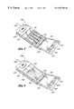
- FIG. 1is a perspective view of a personal communicator constructed in accordance with a first embodiment of the present invention, showing a display on the flip element of the device.
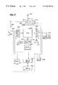
- FIG. 2is a block diagram of the circuitry of the personal communicator shown in FIG. 1 .
- FIG. 3is a perspective view of a personal communicator constructed in accordance with a second embodiment of the present invention, showing displays on the body portion and on the flip element of the device.
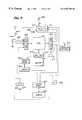
- FIG. 4is a block diagram of the circuitry of the personal communicator shown in FIG. 3 .
- FIG. 5is a front plan view of the flip element of either of the personal communicators shown in FIGS. 1 and 3, showing an example display output that indicates functions performed by input keys on the flip element.
- FIG. 6is a perspective view of either of the personal communicators shown in FIGS. 1 and 3, showing the personal communicator in a compact, folded configuration.
- FIG. 7is a high level flowchart illustrating a process that is performed when a personal communicator receives a data message.
- a first embodimentshown in FIGS. 1 and 2 comprises a portable radiotelephone having a telephone keypad on the body portion with and display on the flip element.
- a second embodimentshown in FIGS. 3 and 4, comprises a portable radiotelephone having a first display on the body portion a second display on the flip element.
- FIGS. 5, 6 and 7are applicable to both radiotelephone embodiments.
- radiotelephoneshave data message handling capabilities, permitting users to send and receive data messages, such as textual messages provided in accordance with a short message service (SMS) standard.
- SMSshort message service
- the radiotelephoneswill hereinafter be referred to as “personal communicators.”
- FIG. 1A portable, personal communicator 100 according to a first embodiment of the present invention is shown in FIG. 1.
- FIG. 2A block diagram of the internal circuitry of the personal communicator 100 is shown in FIG. 2 .
- the personal communicator 100has two main portions, a body portion 101 and a flip element 121 .
- the body portion 101 and the flip element 121are connected by a hinge 131 .
- the body portion 101is configured for placement to the ear of a user.
- the body portion 101 and the flip element 121are positioned relative to one another such that a user of the personal communicator 100 may place an ear against an earpiece 105 and may speak into a mouthpiece 129 when the flip element 121 is in an open angular position (as shown in FIG. 1 ).
- a keypad 103is provided on the body portion 101 .
- the keypad 103includes standard telephone number dialing keys (labeled 0-9, * and # in FIG. 1 ), and additional keys to facilitate wireless telephone communications. Additional keys or switches (not shown) may be provided to perform functions such as power on/off, channel select, volume control, and telephone number recall.
- the personal communicator 100may also include various adapter outlets (not shown), such as an AC power adapter outlet, an audio outlet for headphones, or a communications adapter outlet for direct communications between the personal communicator 100 and a personal computer.
- a rechargeable battery packthe location of which is generally shown at 107 , enables the personal communicator 100 to be recharged, for example, by mechanically coupling a charging contact (not shown) on the battery pack 107 to a base station (not shown).
- An antenna 109enables wireless communication between the personal communicator 100 and other devices in a communications network.
- the flip element 121When the flip element 121 is open as shown in FIG. 1, a built-in display 123 is visible to a user of the personal communicator 100 .
- the display 123may be a conventional LCD or plasma display, or another type of lightweight, lower-power display.
- the display 123advantageously provides various types of visual information to the user of the personal communicator 100 , such as alphanumeric text, or graphic or video images.
- the flip element 121also includes input keys 125 , 126 , and 127 to allow a user to input information into the personal communicator 100 .
- the display 123may be used for output only, in which case user input is accomplished primarily through the use of the input keys 125 , 126 , and 127 and the keypad 103 .
- the display 123is preferably a conventional touch sensitive display, such as a DMF series LCD Touch Screen available from Optrex, that can be used for input as well as output.
- the use of a touch sensitive displayenables the user to input information by touching menu items presented on the display 123 .
- a usercan additionally or alternatively input information by writing on the display 123 with a stylus (not shown).
- a conventional character recognition meanscan advantageously be included to facilitate input of information using the stylus.
- the personal communicator 100may be configured to accept and process an audio input, in which case the personal communicator 100 may be equipped with a voice recognition capability.
- a central processing unit (“CPU”) 201is connected to an input port 208 and an output port 209 .
- the CPU 201is also connected to non-volatile random access memory (“RAM”) 215 and read-only memory (“ROM”) 216 .
- RAMnon-volatile random access memory
- ROMread-only memory
- one or more of the CPU 201 , the input and output ports 208 and 209 , the RAM 215 and the ROM 216may be integrated into a conventional microprocessor, microcontroller, or application-specific integrated circuit (ASIC). It will further be recognized that multiple CPU's can be provided, with, for example, one or more CPU's acting as a slave to a master CPU.
- the switch 230is connected between a line 232 and a voltage source (+V), such that the line 232 is held high (at approximately +V volts) when the switch is closed.
- a pull-down resistor 234pulls the line 232 to ground when the switch 230 is open.
- the switch 230is preferably formed within a hinge portion 131 of the personal communicator 100 such that the switch 230 transitions between an open and a closed state as the flip element 121 is pivoted past a predetermined angular position relative to the body portion 101 .
- the switch 230may be a contact switch, hook switch, magnetically activated switch, or other device conventionally used for a similar purpose.
- the switch 230is used by the CPU 201 to activate the display 123 when the flip element 121 is folded to an open position, and may further be used to switch the personal communicator 100 between various modes (modes discussed below).
- a speaker 205Connected to the output port 209 are a speaker 205 , an optional mechanical vibrator 212 for alerting a user, a transmitter (“Tx”) 214 , a display driver 223 , and a ringer 211 .
- the display driver 223is connected to the display 123 . If the display 123 is a touch sensitive display, the display driver 223 is also connected to the input port 208 , as shown by a dashed line in FIG. 2 .
- the speaker 205is situated proximately behind the earpiece 105 so that the user of the personal communicator 100 is able to hear the sounds generated by the speaker 205 .
- the receiver 213In addition to being connected to the input port 208 , the receiver 213 is connected to the antenna 109 and to the speaker 205 .
- the transmitter 214in addition to being connected to the output port 209 , is connected to the antenna 109 and to a microphone (MIC) 229 .
- the microphone 229is situated proximately behind the mouthpiece 129 (FIG. 1) in order to pick up the voice of the user of the personal communicator 100 . If the personal communicator 100 is equipped to accept and process audio input, the microphone 229 is also connected to the input port 208 , as shown by a dashed line in FIG. 2 .
- a battery 207provides the electrical power necessary to operate the various electrical components of the personal communicator 100 . While the actual electrical connections of the battery 207 are not shown in FIG. 2, conventional means are employed to supply electrical power from the battery 207 to the various electrical components of the personal communicator 100 .
- the type of information that the CPU 201 outputs to, or inputs from, the display 123depends on the software which the CPU 201 is executing at a given time.
- Software application programsmay be loaded into RAM 215 from ROM 216 or from another type of non-volatile storage device (not shown), such as a flash memory card or a miniature disk drive that is mounted within or interfaced to the personal communicator 100 .
- Application programsmay also be transmitted to the personal communicator 100 from a remote storage device, or “downloaded” directly to the personal communicator 100 , for example, via a communications adapter that links the personal communicator 100 to a personal computer.
- Once an application program is loaded into RAM 215the program may be executed by the CPU 201 .
- Applicationsmay be executed partially by the CPU 201 and partially by remote processing means operating in a “client/server” relationship, allowing the personal communicator 100 to access greater storage and processing resources than are available within the personal communicator 100 itself.
- an application programhas access to all of the I/O devices to which the CPU 201 is interfaced.
- an applicationcan send and receive radio frequency signals via the receiver 213 and the transmitter 214 , can input and output audio information via the microphone 229 and the speaker 205 , can input information from the keypad 103 and the input keys 125 , 126 , and 127 , and can output visual information to, and input visual information from, the display 123 .
- the personal communicator 100is advantageously suitable for a variety of communications applications.
- the display 123may be used to display message data received under the control of an application program.
- the display 123can be used to display short message service (SMS) messages that are in accordance with an SMS standard published by the CCITT.
- SMSshort message service
- the display 123can also be used to display fax messages, e-mail messages, beeper messages, and other types of messages sent in accordance with conventional communications protocols.
- the display 123can further be used to display status information for the personal communicator 100 and for application programs that are being executed, and to allow the user to select from a plurality of menu options.
- the display 123may also be used to compose data message, in which case an alphanumeric keypad may be shown on the display 123 .
- the display 123can further be used to display directories of names and phone numbers stored in RAM 215 .
- displayed telephone numberscan further be selected for dialing by depressing a corresponding portion of the display 123 .
- the telephone keypad 103may be used to place telephone calls, including voice telephone calls and calls placed to initiate data communications.
- the telephone keypad 103may further be used (with a template or otherwise) to allow a user to generate a data message to send.
- the telephone keypad 103may further be used to allow a user to enter a password to access certain types of data messages.
- the personal communicator 100when the flip element 121 is in the closed position (as shown in FIG. 6 ), the personal communicator 100 operates in a “voice communications receive mode,” wherein the personal communicator 100 can receive incoming cellular phone calls but cannot accept data messages.
- the personal communicator 100is configured to accept both telephone calls and data messages when the flip element 121 is in the closed position.
- the personal communicator 100can alert a user to an incoming telephone call by activating the ringer 211 or the vibrator 212 .
- the personal communicator 100optionally may be programmed to execute a voice mail application to record the caller's voice message in RAM 215 immediately or after a preprogrammed number of rings.
- the display 123is maintained in an off state when the flip element 121 is closed, to conserve power.
- the personal communicator 100When the flip element 121 is in an open position, the personal communicator 100 is preferably switchable between a “voice mode,” a “display mode,” and a “dual mode,” as specified by the user.
- the mode that the personal communicator 100 “comes up” in when the flip element 121 is initially openedmay be pre-specified by the user.
- the voice modethe personal communicator 100 operates like a standard radiotelephone, allowing a user to dial telephone numbers, answer incoming telephone calls, and carry on telephone conversations.
- the components of the personal communicator 100 that are not required for voice communications, such as the display 123are advantageously turned off or maintained in a low-power state while the personal communicator 100 operates in the voice mode.
- the display 123is active, allowing the user to select a function from a menu of options that allow the user to interact with software application programs. For example, the user can select between menu items that allow the user to create a data message, send a data message, or view a data message previously stored to RAM 215 .
- Menu optionscan be selected using the keys 125 , 126 and 127 .
- FIG. 6which illustrates a sample menu on the display 123 , the keys 125 , 126 and 127 preferably serve functions that are software-definable, with portions of the display 123 proximate to the keys 125 , 126 , 127 indicating the functions performed by the respective keys.
- the key 125when the user is viewing a received data message, the key 125 may be defined as a scroll key which permits the user to scroll forward through the displayed message.
- menu itemsmay additionally or alternatively be selected by depressing a portion of the display 123 .
- the dual modeis a combination of the voice and display modes.
- the dual modeadvantageously allows a user to interact with software application programs while simultaneously carrying on a telephone conversation.
- the personal communicator 100may be equipped with a headphones socket (not shown) and/or a “speakerphone” capability, so that a user can simultaneously hear another party's voice, view the display 123 , and input information into the personal communicator 100 .
- Switching between the various operating modes available when the flip element 121 is openis preferably accomplished manually by a user, for example, by the use of one or more of the keys 125 , 126 , 127 on the personal communicator 100 .
- Mode switchingmay also be accomplished automatically in response to particular events. For example, when an incoming telephone voice call is answered, such as by the user opening the flip element 121 , the personal communicator 100 may automatically enter voice mode. Additional operating modes may be utilized in order to obtain the best combination of ease-of-use and long battery life for the personal communicator 100 .
- the personal communicator 100may alert a user to an incoming telephone call or data message audibly using the ringer 211 , visually using the display 123 (when the display 123 is active), or physically using the vibrator 212 .
- the specific means used to alert the usercan be preprogrammed by the user. Further, the personal communicator 100 can be configured such that the particular means used to alert the user indicates the type of communication being received (e.g., telephone call, data message, emergency data message, fax, etc.).
- FIG. 3A block diagram of the internal circuitry of the personal communicator 300 is shown in FIG. 4 .
- the personal communicator 300has a body portion 301 , an earpiece 305 , a rechargeable battery pack shown generally by 307 , an antenna 309 , a flip element 321 , input keys 325 , 326 and 327 , a mouthpiece 329 , and a hinge 331 that are preferably substantially identical to the body portion 101 , earpiece 105 , rechargeable battery pack 107 , antenna 109 , flip element 121 , input keys 125 , 126 and 127 , mouthpiece 129 , and hinge 131 respectively described above for the personal communicator 100 .
- a first display 303is disposed on the body portion 301 , in place of the keypad 103 of FIG. 1.
- a second display 323is disposed on the flip element 321 .
- the first display 303 and the second display 323may be conventional LCD or plasma displays, or other types of lightweight, lower-power displays. In the preferred embodiment, both displays 303 and 323 are DMF series LCD displays available from Optrex, with at least one of the two displays being touch sensitive.
- the first display 303 and the second display 323may provide any type of visual information to the user of the personal communicator 300 , such as alphanumeric text, graphics, or video images.
- the first display 303is a touch sensitive display that can be used for both input and output of information.
- the first display 303may display a visual facsimile of a telephone keypad (as shown in dashed lines in FIG. 3 ), allowing a user to dial a telephone number by pressing a finger repeatedly on the surface of the display 303 .
- the display 303may also be employed in other ways to facilitate telephone number dialing.
- the display 303may present a directory of telephone numbers, allowing a user to dial a telephone number by simply touching a directory entry.
- the personal communicator 300may be equipped with a handwriting recognition capability, allowing a user to dial a telephone number by hand writing the number on the display 303 with a stylus.
- the second display 323may be a touch sensitive display that provides for input of data.
- the personal communicator 300may be equipped with a voice recognition capability, so that a user of the personal communicator 300 may dial a telephone number by simply speaking into the mouthpiece 329 .
- the specific functions of the displays 303 and 323depend on the specific implementation of the personal communicator 300 , as well as on the software application being executed by the personal communicator 300 .
- both displaysmay be used for output, both for input, or either one of the displays 303 or 323 may be used for input while the other display is used for output.
- the addition of the second display 303provides a greater display area for displaying received messages over the personal communicator 100 of FIG. 1 . This facilitates the display of relatively long messages that are commonly encountered with certain types of communications applications.
- one displaycan be used to display messages while the other display is used to display menu items.
- messagescan be displayed on the display 303 , while the display 323 displays menu items that allow the user to scroll through the displayed message, zoom-in on the message (with facsimile messages, for example), edit the displayed message, or save the message to memory.
- a terminal emulation programmay display a visual facsimile of a conventional “QWERTY” typewriter keyboard on the first display 303 while displaying a user-input text message (input using the QWERTY typewriter keyboard) on the second display 323 .
- a voice mail applicationmay display a menu of options for managing voice messages on the first display 303 , while the second display 323 displays helpful information regarding the voice mail options displayed on the first display 303 .
- FIG. 4a block diagram of the internal circuitry of the personal communicator 300 is shown, with arrows indicating the direction of information flow between the various electrical components of the personal communicator 300 .
- a CPU 401is connected to an input port 408 and an output port 409 .
- the CPU 401is also connected to a nonvolatile RAM 415 and a ROM 416 .
- Connected to the input port 408are the input keys 325 , 326 , and 327 , a switch 430 , and a receiver (“Rx”) 413 .
- the switch 430is connected between a line 432 and a voltage source (+V).
- a pull-down resistor 434is connected between the line 432 and ground.
- the switch 430 , input keys 325 , 326 , 327 , and receiver 413are structurally and functionally substantially identical to the switch 230 , input keys 125 , 126 , 127 , and receiver 213 of FIG. 2 .
- a speaker 405Connected to the output port 409 are a speaker 405 , an optional mechanical vibrator 412 , a transmitter (“Tx”) 414 , a first display driver 403 , a second display driver 423 , and a ringer 411 .
- the vibrator 412 and transmitter 414perform substantially the same functions as the vibrator 212 and transmitter 214 of FIG. 2 .
- the first display driver 403is connected to the first display 303
- the second display driver 423is connected to the second display 323 . If the first display 303 is a touch sensitive display, the first display driver 403 is connected to the input port 408 , as represented by a dashed line in FIG. 4 .
- the second display driver 423is also connected to the input port 408 , as represented by a dashed line in FIG. 4 .
- the speaker 405is situated proximately behind the earpiece 305 so that the user of the personal communicator 300 is able to hear the sounds generated by the speaker 405 .
- the receiver 413is connected to the antenna 309 and to the speaker 405 .
- the transmitter 414in addition to being connected to the output port 409 , is connected to the antenna 309 and to the microphone 429 .
- the microphone 429is situated proximately behind the mouthpiece 329 in order to pick up the voice of the user of the personal communicator 300 . If the personal communicator 300 is equipped to accept and process audio input, the microphone 429 is also connected to the input port 408 , as shown by a dashed line in FIG. 4 .
- the components of the personal communicator 300serve the same or similar functions as the like-named components of the personal communicator 100 .
- the personal communicator 300 of the second embodimentreplaces the telephone keypad 103 of the first embodiment with the first display 303 and the first display driver 403 , significantly increasing the total display area.
- Both displays 303 and 323are turned off by the CPU 401 when the flip element 321 is closed.
- the flip element 321is open, one or both of the displays 303 , 323 may be turned on by the CPU 401 .
- one of the two displays 303 or 323may be maintained in an off state by the CPU 401 when it is not needed, and may be automatically switched on only when an application requires additional display area. Power may thereby be conserved.
- the input keys 325 , 326 , and 327are software definable, as with the keys 125 , 126 and 127 of the personal communicator 100 .
- additional software-definable keysmay be provided on the body portion 301 proximate to the display 303 .
- keysmay be provided in the area generally indicated by the reference number 340 .
- FIG. 6illustrates the configuration of either of the personal communicators 100 and 300 when the flip element 121 , 321 is folded inward to meet with the body portion 101 , 301 .
- this method of closing the personal communicatoradvantageously serves to protect the display 123 (FIG. 1) or displays 303 , 323 (FIG. 3) of the personal communicator 100 , 300 from physical damage, while further serving to switch the displays 123 , 303 , 323 to an off state.
- the personal communicators 100 and 300preferably include software that permits data messages to be transferred over a cellular network in accordance with a short message service (SMS) standard.
- SMSshort message service
- Various short message servicesare currently in use in Europe.
- CCITTis currently developing an SMS standard.
- Messages transmitted in accordance with a particular standardtypically contain attributes that specify how the message should be treated by the personal communicator.
- a messagemay have a priority indicator (indicating, for example, priorities of “emergency,” “urgent,” “normal,” and “interactive”), a time and date indicator (indicating the time and date the message was sent), a validity period indicator (indicating a period of time for which the message should be retained by the receiver), a privacy indicator (indicating, for example, whether or not the message is confidential), and an acknowledgement indicator (indicating whether the sending application requested an acknowledgement that the message was received).
- a priority indicatorindicating, for example, priorities of “emergency,” “urgent,” “normal,” and “interactive”
- time and date indicatorindicating the time and date the message was sent
- a validity period indicatorindicating a period of time for which the message should be retained by the receiver
- a privacy indicatorindicating, for example, whether or not the message is confidential
- an acknowledgement indicatorindicating whether the sending application requested an acknowledgement that the message was received.
- FIG. 7illustrates in a flow chart for a typical sequence of steps that are performed when a data message, such as a message transmitted in accordance with an SMS standard, is received by a personal communicator.
- the sequence of eventsis applicable to both of the above-described personal communicators 100 and 300 , although the method by which each step is performed may differ.
- the personal communicator 100 or 300will initially decide whether or not to alert the user. This decision may be based, for example, on the priority attribute of the message (if any), on the position flip element 121 , 321 , and on how the particular personal communicator 100 or 300 has been configured by the user. If a decision is made not to alert the user, the message may be stored to memory 215 , 415 , as indicated by the block 730 .
- the personal communicator 100 or 300will generate an audible tone from the ringer 211 , 411 , activate the mechanical vibrator 212 , 412 , or generate a visual display (such as a flashing icon) on a screen, as indicated by the block 708 .
- the particular method for alerting the userpreferably depends upon how the personal communicator 100 or 300 has been configured or preprogrammed by the user, and may also depend upon the type of message received.
- the personal communicator 100 or 300will enter into a loop while waiting for the user to take an action, as indicated by the blocks 710 , 712 and 714 .
- the usermay take an action in response to the incoming message, for example, by depressing one of the keys 125 - 127 or 325 - 327 , or by depressing a portion of a touch sensitive screen 123 , 303 , or 323 that has an incoming message icon displayed thereon.
- Appropriate menu optionsmay be provided at this time on one of the screens to indicate the various actions that can be taken (e.g., read message, store message, etc.). If no action is taken within a preprogrammed timeout period, the message may automatically be transferred to memory 215 , 415 , as indicated by the blocks 714 and 716 .
- the personal communicator 100 or 300may check to determine whether a confidentiality attribute is included within the message. If the message is confidential, the personal communicator 100 or 300 may prompt the user to enter a password, as indicated by the block 726 .
- a passwordmay be entered, for example, by depressing a sequence of numbers on the keypad 103 (FIG. 1 ), or by entering a sequence of characters displayed on a screen 123 , 303 , or 323 . Access to the message will be denied if a correct password is not entered, as indicated by the blocks 728 and 730 .
- the messagewill be displayed, as indicated by the block 734 .
- the messageis displayed on the screen 123 .
- the messagemay be displayed on one or both of the screens 303 and 323 .
- a software-definable key 125 - 127 or 325 - 327may then be used to scroll through the message, or to select an appropriate option for handling the message (e.g., discard, store, forward, reply, etc.).
- one of the two screens 303 and 321may advantageously be used for displaying these various options while the other screen is used to display the message.
- the personal communicator 100 or 300may check an acknowledgement indicator attribute of the message. If an acknowledgement request is present, the personal communicator 100 or 300 transmits an acknowledgement message to the sender as indicated by the block 746 , indicating that the message has been received and viewed. An acknowledgement message may alternatively be transmitted when the message is first received by the personal communicator 100 or 300 . Finally, as indicated by the blocks 730 , 748 and 750 , the personal communicator 100 or 300 either discards the message or saves the message to RAM 215 , 415 , at the option of the user.
Landscapes
- Engineering & Computer Science (AREA)
- Signal Processing (AREA)
- Human Computer Interaction (AREA)
- Computer Networks & Wireless Communication (AREA)
- Telephone Set Structure (AREA)
- Mobile Radio Communication Systems (AREA)
Abstract
Description
Claims (26)
Priority Applications (2)
| Application Number | Priority Date | Filing Date | Title |
|---|---|---|---|
| US08/979,110US6587700B1 (en) | 1994-06-23 | 1997-11-26 | Personal communicator with flip element display |
| US10/455,125US7310540B2 (en) | 1994-06-23 | 2003-06-05 | Personal communicator with flip element display |
Applications Claiming Priority (4)
| Application Number | Priority Date | Filing Date | Title |
|---|---|---|---|
| US29/024,955USD363281S (en) | 1994-06-23 | 1994-06-23 | Wireless communications terminal |
| US34903294A | 1994-12-02 | 1994-12-02 | |
| US74146396A | 1996-10-31 | 1996-10-31 | |
| US08/979,110US6587700B1 (en) | 1994-06-23 | 1997-11-26 | Personal communicator with flip element display |
Related Parent Applications (2)
| Application Number | Title | Priority Date | Filing Date |
|---|---|---|---|
| US34903294AContinuation | 1994-06-23 | 1994-12-02 | |
| US74146396AContinuation | 1994-06-23 | 1996-10-31 |
Related Child Applications (1)
| Application Number | Title | Priority Date | Filing Date |
|---|---|---|---|
| US10/455,125ContinuationUS7310540B2 (en) | 1994-06-23 | 2003-06-05 | Personal communicator with flip element display |
Publications (1)
| Publication Number | Publication Date |
|---|---|
| US6587700B1true US6587700B1 (en) | 2003-07-01 |
Family
ID=27362430
Family Applications (2)
| Application Number | Title | Priority Date | Filing Date |
|---|---|---|---|
| US08/979,110Expired - Fee RelatedUS6587700B1 (en) | 1994-06-23 | 1997-11-26 | Personal communicator with flip element display |
| US10/455,125Expired - Fee RelatedUS7310540B2 (en) | 1994-06-23 | 2003-06-05 | Personal communicator with flip element display |
Family Applications After (1)
| Application Number | Title | Priority Date | Filing Date |
|---|---|---|---|
| US10/455,125Expired - Fee RelatedUS7310540B2 (en) | 1994-06-23 | 2003-06-05 | Personal communicator with flip element display |
Country Status (1)
| Country | Link |
|---|---|
| US (2) | US6587700B1 (en) |
Cited By (66)
| Publication number | Priority date | Publication date | Assignee | Title |
|---|---|---|---|---|
| US20010011029A1 (en)* | 2000-01-27 | 2001-08-02 | Kyocera Corporation | Portable radio communication apparatus |
| US20010036844A1 (en)* | 2000-02-29 | 2001-11-01 | Matsushita Electric Industrial Co., Ltd. | Mobile telephone with electronic mail function |
| US20010037355A1 (en)* | 2000-04-07 | 2001-11-01 | Britt Joe Freeman | Distinctive vibrate system, apparatus and method |
| US20020065662A1 (en)* | 2000-07-11 | 2002-05-30 | Sherman William F. | Voice recognition peripheral device |
| US20020119802A1 (en)* | 2001-02-28 | 2002-08-29 | Nec Corporation | Portable cellular phone |
| US20020119807A1 (en)* | 2001-02-23 | 2002-08-29 | Hsi-Che Lee | Mobile phone with electronic voice date book |
| US20020151296A1 (en)* | 2001-04-16 | 2002-10-17 | Nec Corporation | Folding portable terminal capable of operating responsive to contents of incoming by being opened |
| US20020155820A1 (en)* | 2001-04-23 | 2002-10-24 | Shih-Min Wang | Mobile communicator |
| US20020193143A1 (en)* | 2001-06-18 | 2002-12-19 | Nec Corporation | Foldable mobile communication terminal and calling method thereof |
| US20030034987A1 (en)* | 2001-08-17 | 2003-02-20 | William Webb | Handheld computer having moveable segments that can be adjusted to affect a size of the handheld computer |
| US20030073456A1 (en)* | 2001-10-16 | 2003-04-17 | Griffin Jason T. | Handheld mobile communication device |
| US20030092467A1 (en)* | 2001-11-09 | 2003-05-15 | Kozo Masuda | Communication terminal apparatus |
| US20030144023A1 (en)* | 2001-10-24 | 2003-07-31 | Woods Gregory Kent | Portable communication device having back-lighting and high key press noise margin |
| US20030148799A1 (en)* | 2002-02-06 | 2003-08-07 | Gvc Corporation | Electricity saving device for a user interface terminal device of cellular phone |
| US20030148752A1 (en)* | 2002-02-06 | 2003-08-07 | Gvc Corporation | Electricity saving method for a user interface terminal device of cellular phone |
| US20030211872A1 (en)* | 1994-06-23 | 2003-11-13 | Meins Charlene L. | Personal communicator with flip element display |
| US20030216157A1 (en)* | 2002-05-14 | 2003-11-20 | High Tech Computer Corp. | Wireless communication apparatus with a flat speaker |
| US20030222846A1 (en)* | 2002-05-31 | 2003-12-04 | Huy Nguyen | Multi-functional handheld device having moveable segments |
| US20030222847A1 (en)* | 2002-05-31 | 2003-12-04 | Huy Nguyen | Handheld computer having an adjustable length for selectively exposing a surface component |
| US20040082361A1 (en)* | 2002-10-18 | 2004-04-29 | Bala Rajagopalan | Handeld, portable electronic computing and communication device and methods for using the same |
| US6747635B2 (en)* | 2000-12-16 | 2004-06-08 | Kamran Ossia | Multi-mode handheld computer |
| US20040155861A1 (en)* | 2002-05-30 | 2004-08-12 | Jackson Iii Robert P. | Portable display monitor |
| US20040203794A1 (en)* | 2002-05-06 | 2004-10-14 | Brown Barbara L. | System and method for providing an automatic response to a telephone call |
| US20050043056A1 (en)* | 1999-10-11 | 2005-02-24 | Boesen Peter V. | Cellular telephone and personal digital assistant |
| US20060234784A1 (en)* | 2004-12-21 | 2006-10-19 | Silviu Reinhorn | Collapsible portable display |
| US20060232578A1 (en)* | 2004-12-21 | 2006-10-19 | Silviu Reinhorn | Collapsible portable display |
| US20060248597A1 (en)* | 2005-04-29 | 2006-11-02 | Matsushita Electric Industrial Co., Ltd. | Ubiquitous personal station with an external case and a control method thereof |
| US20060270460A1 (en)* | 2005-05-24 | 2006-11-30 | Katja Konkka | Mobile communication terminal and mobile communication system, and method therefore |
| US20070040669A1 (en)* | 2003-09-30 | 2007-02-22 | Koninkjike Phillips Electronics N.V. | Communications device comprising a receiver for important information, method of transmitting such information, and transmitting system using such a method |
| US20070049326A1 (en)* | 2005-08-24 | 2007-03-01 | Lg Electronics Inc. | Mobile terminal with internal antenna structure having a sound resonance chamber |
| US7222164B1 (en)* | 1999-08-24 | 2007-05-22 | Axalto Sa | Device and method to load commands in an integrated circuit card |
| US20070191070A1 (en)* | 1996-12-16 | 2007-08-16 | Rao Raman K | Reconfigurable mobile device interfaces supporting authenticated high-quality video, audio, TV and multimedia services |
| US20070293274A1 (en)* | 1999-10-15 | 2007-12-20 | Arnold Gieseke | Mobile telecommunications terminal |
| WO2008055513A1 (en)* | 2006-11-06 | 2008-05-15 | Nokia Corporation | Wireless mobile communication terminal with adaptive user interface |
| US20080129465A1 (en)* | 1996-12-16 | 2008-06-05 | Rao Raman K | System for seamless and secure networking of implantable medical devices, electronic patch devices and wearable devices |
| US20080132300A1 (en)* | 2006-11-30 | 2008-06-05 | Motorola, Inc. | Method and apparatus for controlling operation of a portable device by movement of a flip portion of the device |
| US20080142603A1 (en)* | 2006-11-01 | 2008-06-19 | Gerhard Stephanus Mynhardt | Portable Industrial Data Capturing Device |
| US7437179B1 (en)* | 1999-10-08 | 2008-10-14 | Nokia Corporation | Radio communication device |
| US20080280596A1 (en)* | 2004-08-10 | 2008-11-13 | Avaya Inc. | Server-Coordinated Ringtones |
| US20090031253A1 (en)* | 2007-07-26 | 2009-01-29 | Lg Electronics Inc. | Mobile terminal and method of displaying menu icon thereof |
| US7505785B2 (en) | 1993-10-13 | 2009-03-17 | Dataquill Limited | Data entry systems |
| US20090302578A1 (en)* | 2008-06-09 | 2009-12-10 | Orbit Baby, Inc. | Multiple interface stroller apparatus and systems |
| US7692667B2 (en) | 2001-08-17 | 2010-04-06 | Palm, Inc. | Handheld computer having moveable segments that are interactive with an integrated display |
| US7804489B1 (en)* | 2001-08-29 | 2010-09-28 | Palmsource Inc. | Method and apparatus for displaying information in a display screen region identified by permanent printing |
| US20110059777A1 (en)* | 1999-06-04 | 2011-03-10 | Ip Holdings, Inc. | Reconfigurable mobile device interfaces supporting authenticated high quality video, audio, tv and multimedia services |
| US8103313B2 (en) | 1992-11-09 | 2012-01-24 | Adc Technology Inc. | Portable communicator |
| US8150482B2 (en) | 2008-01-08 | 2012-04-03 | Hewlett-Packard Development Company, L.P. | Mobile computing device with moveable housing segments |
| US8200298B2 (en) | 2008-01-08 | 2012-06-12 | Hewlett-Packard Development Company, L.P. | Keypad housing configuration for a mobile computing device |
| US8233948B2 (en) | 2007-12-11 | 2012-07-31 | Hewlett-Packard Development Company, L.P. | Slider assembly for a housing of a mobile computing device |
| USRE43931E1 (en)* | 1997-12-30 | 2013-01-15 | Ericsson Inc. | Radiotelephones having contact-sensitive user interfaces and methods of operating same |
| US8965460B1 (en) | 2004-01-30 | 2015-02-24 | Ip Holdings, Inc. | Image and augmented reality based networks using mobile devices and intelligent electronic glasses |
| US9300645B1 (en) | 2013-03-14 | 2016-03-29 | Ip Holdings, Inc. | Mobile IO input and output for smartphones, tablet, and wireless devices including touch screen, voice, pen, and gestures |
| WO2018118432A1 (en)* | 2016-12-23 | 2018-06-28 | Realwear, Incorporated | Interchangeable optics for a head-mounted display |
| US10142496B1 (en) | 2013-01-26 | 2018-11-27 | Ip Holdings, Inc. | Mobile device image capture and image modification including filters, superimposing and geofenced comments in augmented reality |
| US10140514B1 (en) | 2004-01-30 | 2018-11-27 | Ip Holdings, Inc. | Capturing and sharing images with mobile device users including for a limited duration of time |
| US10365493B2 (en) | 2016-12-23 | 2019-07-30 | Realwear, Incorporated | Modular components for a head-mounted display |
| US10393312B2 (en) | 2016-12-23 | 2019-08-27 | Realwear, Inc. | Articulating components for a head-mounted display |
| US10620910B2 (en) | 2016-12-23 | 2020-04-14 | Realwear, Inc. | Hands-free navigation of touch-based operating systems |
| US20200322966A1 (en)* | 2009-09-11 | 2020-10-08 | Aerovironment, Inc. | Dynamic transmission control for a wireless network |
| US10936872B2 (en) | 2016-12-23 | 2021-03-02 | Realwear, Inc. | Hands-free contextually aware object interaction for wearable display |
| US10983753B2 (en) | 2017-06-09 | 2021-04-20 | International Business Machines Corporation | Cognitive and interactive sensor based smart home solution |
| US20210175987A1 (en)* | 2018-01-26 | 2021-06-10 | Clip Interactive, Llc | Seamless Integration of Radio Broadcast Audio with Streaming Audio |
| US11099716B2 (en) | 2016-12-23 | 2021-08-24 | Realwear, Inc. | Context based content navigation for wearable display |
| US11455799B2 (en) | 2004-01-30 | 2022-09-27 | Airspace Reality | Image networks for mobile communication |
| US11507216B2 (en) | 2016-12-23 | 2022-11-22 | Realwear, Inc. | Customizing user interfaces of binary applications |
| US20250097338A1 (en)* | 2023-09-14 | 2025-03-20 | Michelle Candelaria Cooper | Systems and Methods for Emergency Contact and Response |
Families Citing this family (18)
| Publication number | Priority date | Publication date | Assignee | Title |
|---|---|---|---|---|
| TW576601U (en)* | 2003-05-09 | 2004-02-11 | Hon Hai Prec Ind Co Ltd | Multi-functional mobile phone |
| KR100697416B1 (en)* | 2003-09-30 | 2007-03-20 | 교세라 가부시키가이샤 | Computer-readable recording media recording mobile communication terminals, information providing systems and programs |
| US7729729B2 (en)* | 2003-11-21 | 2010-06-01 | Samsung Electronics Co., Ltd | Method for displaying information in a mobile communication terminal |
| KR100677303B1 (en)* | 2003-12-26 | 2007-02-05 | 엘지전자 주식회사 | Mobile terminal |
| KR100600750B1 (en)* | 2004-07-27 | 2006-07-14 | 엘지전자 주식회사 | Mobile terminal equipped with dual camera |
| KR100690726B1 (en)* | 2004-09-14 | 2007-03-09 | 엘지전자 주식회사 | Multi-tasking mobile terminal and its control method |
| US20060217148A1 (en)* | 2005-03-23 | 2006-09-28 | Eastman Kodak Company | Camera phone with large sensor |
| JP2007006173A (en)* | 2005-06-24 | 2007-01-11 | Fujitsu Ltd | Electronic device, screen information output method and program |
| KR20070023049A (en)* | 2005-08-23 | 2007-02-28 | 삼성전자주식회사 | User Interface Method for Silver Generation in Mobile Communication Devices |
| WO2007073001A1 (en)* | 2005-12-22 | 2007-06-28 | Showa Denko K.K. | Light-emitting diode and method for fabricant thereof |
| US20070222772A1 (en)* | 2006-03-23 | 2007-09-27 | Amick Melissa A | System and method for assisting those with diminished mental capacities |
| US20070268264A1 (en)* | 2006-05-16 | 2007-11-22 | Nokia Corporation | Electronic devices |
| JP4127842B2 (en)* | 2006-06-05 | 2008-07-30 | 株式会社東芝 | Information processing device |
| KR101141616B1 (en)* | 2006-11-20 | 2012-05-17 | 엘지전자 주식회사 | MIDlet executing terminal, and method thereof |
| US8886252B2 (en)* | 2008-12-22 | 2014-11-11 | Htc Corporation | Method and apparatus for automatically changing operating modes in a mobile device |
| US8599105B2 (en) | 2010-07-02 | 2013-12-03 | Nokia Corporation | Method and apparatus for implementing a multiple display mode |
| KR20160027757A (en)* | 2014-09-02 | 2016-03-10 | 삼성전자주식회사 | Method for managing heat generated by electronic device and the electronic device therefor |
| CN112584637B (en)* | 2020-12-07 | 2022-03-22 | Oppo广东移动通信有限公司 | electronic device |
Citations (32)
| Publication number | Priority date | Publication date | Assignee | Title |
|---|---|---|---|---|
| USD298036S (en) | 1986-12-27 | 1988-10-11 | Oki Electric Industry Co., Ltd. | Portable handset radio telephone |
| US4845772A (en) | 1988-06-13 | 1989-07-04 | Motorola, Inc. | Portable radiotelephone with control switch disabling |
| USD306298S (en) | 1988-01-28 | 1990-02-27 | Sharp Corporation | Autodialer with electronic telephone directory |
| WO1991012673A1 (en)* | 1990-02-09 | 1991-08-22 | Motorola, Inc. | Radio telephone with detachable selective call receiver |
| USD319441S (en) | 1989-12-07 | 1991-08-27 | Kabushiki Kaisha Toshiba | Portable radiotelephone |
| JPH042223A (en) | 1990-04-19 | 1992-01-07 | Nec Corp | Receiver |
| USD328294S (en) | 1991-04-26 | 1992-07-28 | Texas Instruments Incorporated | Telecommunication device with hinged cover |
| US5175759A (en) | 1989-11-20 | 1992-12-29 | Metroka Michael P | Communications device with movable element control interface |
| US5185790A (en) | 1991-03-28 | 1993-02-09 | Motorola, Inc. | Multiposition detenting hinge apparatus |
| US5260998A (en) | 1990-09-07 | 1993-11-09 | Fujitsu Limited | Folding portable telephone set |
| US5285493A (en) | 1989-01-19 | 1994-02-08 | Kabushiki Kaisha Toshiba | Radio tele-communication device with received message displaying feature |
| USD345355S (en) | 1992-09-15 | 1994-03-22 | Kabushiki Kaisha Toshiba | Portable radio telephone |
| USD345356S (en) | 1992-09-15 | 1994-03-22 | Kabushiki Kaisha Toshiba | Portable radio telephone |
| US5303291A (en)* | 1990-09-07 | 1994-04-12 | Fujitsu Limited | Portable telephone having a detachable functional module |
| JPH06164440A (en)* | 1992-11-16 | 1994-06-10 | Hitachi Ltd | Portable information communication equipment |
| USD348071S (en) | 1992-08-17 | 1994-06-21 | Motorola, Inc. | Microphone flap for a portable telephone |
| JPH06177809A (en)* | 1992-12-11 | 1994-06-24 | Hitachi Ltd | Portable information communication equipment |
| US5333176A (en)* | 1992-04-30 | 1994-07-26 | Murata Machinery, Ltd. | Cellular hand held portable speakerphone system having an interface adapter |
| US5335276A (en)* | 1992-12-16 | 1994-08-02 | Texas Instruments Incorporated | Communication system and methods for enhanced information transfer |
| US5337346A (en)* | 1991-09-26 | 1994-08-09 | Casio Computer Co., Ltd. | Portable telephone apparatus including electronic notebook function |
| USD351594S (en) | 1993-07-08 | 1994-10-18 | U.S. West Advanced Technologies, Inc. | Mobile telephone handset |
| USD355182S (en)* | 1992-09-15 | 1995-02-07 | Kabushiki Kaisha Toshiba | Portable radio telephone |
| US5414444A (en)* | 1994-03-30 | 1995-05-09 | At&T Corp. | Personal communicator having orientable video imaging element |
| US5422656A (en)* | 1993-11-01 | 1995-06-06 | International Business Machines Corp. | Personal communicator having improved contrast control for a liquid crystal, touch sensitive display |
| US5425077A (en)* | 1993-07-08 | 1995-06-13 | U.S. West Advanced Technologies, Inc. | Mobile telephone user interface including fixed and dynamic function keys and method of using same |
| US5436954A (en)* | 1992-09-08 | 1995-07-25 | Hitachi, Ltd. | Foldable radio telephone set with rotary selector integral with foldable hinge element |
| USD363281S (en)* | 1994-06-23 | 1995-10-17 | Mccaw Cellular Communications, Inc. | Wireless communications terminal |
| US5465401A (en)* | 1992-12-15 | 1995-11-07 | Texas Instruments Incorporated | Communication system and methods for enhanced information transfer |
| US5500893A (en)* | 1993-09-14 | 1996-03-19 | Sony Corporation | Telephone apparatus, information processing apparatus and information communication terminal |
| US5661641A (en)* | 1995-06-05 | 1997-08-26 | Sony Corporation | Portable telephone having a reversible and sliding card casing |
| US5668867A (en)* | 1993-12-28 | 1997-09-16 | Nec Corporation | Foldable portable telephone with improved antenna gain |
| US5835732A (en)* | 1993-10-28 | 1998-11-10 | Elonex Ip Holdings, Ltd. | Miniature digital assistant having enhanced host communication |
Family Cites Families (8)
| Publication number | Priority date | Publication date | Assignee | Title |
|---|---|---|---|---|
| US298036A (en)* | 1884-05-06 | Switch-operating mechanism | ||
| US328294A (en)* | 1885-10-13 | Elevator | ||
| US351594A (en)* | 1886-10-26 | Sewing-machine | ||
| US348071A (en)* | 1886-08-24 | Thill-supporter | ||
| US345356A (en)* | 1886-07-13 | Mills w | ||
| US319441A (en)* | 1885-06-09 | Wheel-plow | ||
| US306298A (en)* | 1884-10-07 | John z | ||
| US6587700B1 (en)* | 1994-06-23 | 2003-07-01 | At&T Wireless Services, Inc. | Personal communicator with flip element display |
- 1997
- 1997-11-26USUS08/979,110patent/US6587700B1/ennot_activeExpired - Fee Related
- 2003
- 2003-06-05USUS10/455,125patent/US7310540B2/ennot_activeExpired - Fee Related
Patent Citations (32)
| Publication number | Priority date | Publication date | Assignee | Title |
|---|---|---|---|---|
| USD298036S (en) | 1986-12-27 | 1988-10-11 | Oki Electric Industry Co., Ltd. | Portable handset radio telephone |
| USD306298S (en) | 1988-01-28 | 1990-02-27 | Sharp Corporation | Autodialer with electronic telephone directory |
| US4845772A (en) | 1988-06-13 | 1989-07-04 | Motorola, Inc. | Portable radiotelephone with control switch disabling |
| US5285493A (en) | 1989-01-19 | 1994-02-08 | Kabushiki Kaisha Toshiba | Radio tele-communication device with received message displaying feature |
| US5175759A (en) | 1989-11-20 | 1992-12-29 | Metroka Michael P | Communications device with movable element control interface |
| USD319441S (en) | 1989-12-07 | 1991-08-27 | Kabushiki Kaisha Toshiba | Portable radiotelephone |
| WO1991012673A1 (en)* | 1990-02-09 | 1991-08-22 | Motorola, Inc. | Radio telephone with detachable selective call receiver |
| JPH042223A (en) | 1990-04-19 | 1992-01-07 | Nec Corp | Receiver |
| US5260998A (en) | 1990-09-07 | 1993-11-09 | Fujitsu Limited | Folding portable telephone set |
| US5303291A (en)* | 1990-09-07 | 1994-04-12 | Fujitsu Limited | Portable telephone having a detachable functional module |
| US5185790A (en) | 1991-03-28 | 1993-02-09 | Motorola, Inc. | Multiposition detenting hinge apparatus |
| USD328294S (en) | 1991-04-26 | 1992-07-28 | Texas Instruments Incorporated | Telecommunication device with hinged cover |
| US5337346A (en)* | 1991-09-26 | 1994-08-09 | Casio Computer Co., Ltd. | Portable telephone apparatus including electronic notebook function |
| US5333176A (en)* | 1992-04-30 | 1994-07-26 | Murata Machinery, Ltd. | Cellular hand held portable speakerphone system having an interface adapter |
| USD348071S (en) | 1992-08-17 | 1994-06-21 | Motorola, Inc. | Microphone flap for a portable telephone |
| US5436954A (en)* | 1992-09-08 | 1995-07-25 | Hitachi, Ltd. | Foldable radio telephone set with rotary selector integral with foldable hinge element |
| USD345355S (en) | 1992-09-15 | 1994-03-22 | Kabushiki Kaisha Toshiba | Portable radio telephone |
| USD345356S (en) | 1992-09-15 | 1994-03-22 | Kabushiki Kaisha Toshiba | Portable radio telephone |
| USD355182S (en)* | 1992-09-15 | 1995-02-07 | Kabushiki Kaisha Toshiba | Portable radio telephone |
| JPH06164440A (en)* | 1992-11-16 | 1994-06-10 | Hitachi Ltd | Portable information communication equipment |
| JPH06177809A (en)* | 1992-12-11 | 1994-06-24 | Hitachi Ltd | Portable information communication equipment |
| US5465401A (en)* | 1992-12-15 | 1995-11-07 | Texas Instruments Incorporated | Communication system and methods for enhanced information transfer |
| US5335276A (en)* | 1992-12-16 | 1994-08-02 | Texas Instruments Incorporated | Communication system and methods for enhanced information transfer |
| USD351594S (en) | 1993-07-08 | 1994-10-18 | U.S. West Advanced Technologies, Inc. | Mobile telephone handset |
| US5425077A (en)* | 1993-07-08 | 1995-06-13 | U.S. West Advanced Technologies, Inc. | Mobile telephone user interface including fixed and dynamic function keys and method of using same |
| US5500893A (en)* | 1993-09-14 | 1996-03-19 | Sony Corporation | Telephone apparatus, information processing apparatus and information communication terminal |
| US5835732A (en)* | 1993-10-28 | 1998-11-10 | Elonex Ip Holdings, Ltd. | Miniature digital assistant having enhanced host communication |
| US5422656A (en)* | 1993-11-01 | 1995-06-06 | International Business Machines Corp. | Personal communicator having improved contrast control for a liquid crystal, touch sensitive display |
| US5668867A (en)* | 1993-12-28 | 1997-09-16 | Nec Corporation | Foldable portable telephone with improved antenna gain |
| US5414444A (en)* | 1994-03-30 | 1995-05-09 | At&T Corp. | Personal communicator having orientable video imaging element |
| USD363281S (en)* | 1994-06-23 | 1995-10-17 | Mccaw Cellular Communications, Inc. | Wireless communications terminal |
| US5661641A (en)* | 1995-06-05 | 1997-08-26 | Sony Corporation | Portable telephone having a reversible and sliding card casing |
Non-Patent Citations (3)
| Title |
|---|
| "Simon from Bell South"; Advertisement; 11/93.* |
| "The Front, A Hand-Held Computer", Telephony; Sep. 9 1988; pp. 24-25.** |
| "The IBM Personal Communicator"; Beatty; IEEE SouthEastern Conference, Miami, FL Apr. 10-13, 1994; pp. 423-425.** |
Cited By (109)
| Publication number | Priority date | Publication date | Assignee | Title |
|---|---|---|---|---|
| US8103313B2 (en) | 1992-11-09 | 2012-01-24 | Adc Technology Inc. | Portable communicator |
| US7505785B2 (en) | 1993-10-13 | 2009-03-17 | Dataquill Limited | Data entry systems |
| US8290538B2 (en) | 1993-10-13 | 2012-10-16 | Dataquill Limited | Data entry systems |
| US7920898B2 (en) | 1993-10-13 | 2011-04-05 | Dataquill Limited | Data entry systems |
| US20030211872A1 (en)* | 1994-06-23 | 2003-11-13 | Meins Charlene L. | Personal communicator with flip element display |
| US7310540B2 (en)* | 1994-06-23 | 2007-12-18 | At&T Mobility Ii Llc | Personal communicator with flip element display |
| US20120202563A1 (en)* | 1996-12-16 | 2012-08-09 | Raman Kaliputnam Rao | Touch Screen, Voice, and Keyboard Input and Output to Wireless Devices |
| US8183998B2 (en) | 1996-12-16 | 2012-05-22 | Ip Holdings, Inc. | System for seamless and secure networking of implantable medical devices, electronic patch devices and wearable devices |
| US20070191070A1 (en)* | 1996-12-16 | 2007-08-16 | Rao Raman K | Reconfigurable mobile device interfaces supporting authenticated high-quality video, audio, TV and multimedia services |
| US20080146272A1 (en)* | 1996-12-16 | 2008-06-19 | Rao Sunil K | Image networks for mobile communication |
| US8483754B2 (en) | 1996-12-16 | 2013-07-09 | Ip Holdings, Inc. | Image networks for mobile communication |
| US10469644B1 (en) | 1996-12-16 | 2019-11-05 | Raman Kaliputnam Rao | Configurable mobile device for authenticated communication, voice recognition, and touch sensitive input |
| US8818451B2 (en) | 1996-12-16 | 2014-08-26 | Ip Holdings, Inc. | Image networks for mobile communication |
| US20080129465A1 (en)* | 1996-12-16 | 2008-06-05 | Rao Raman K | System for seamless and secure networking of implantable medical devices, electronic patch devices and wearable devices |
| US8812059B2 (en) | 1997-12-30 | 2014-08-19 | Ericsson, Inc. | Radiotelephones having contact-sensitive user interfaces and methods of operating same |
| USRE43931E1 (en)* | 1997-12-30 | 2013-01-15 | Ericsson Inc. | Radiotelephones having contact-sensitive user interfaces and methods of operating same |
| US10728381B2 (en)* | 1999-06-04 | 2020-07-28 | Raman K. Rao | Reconfigurable mobile device interfaces supporting authenticated high quality video, audio, TV and multimedia services |
| US20110059777A1 (en)* | 1999-06-04 | 2011-03-10 | Ip Holdings, Inc. | Reconfigurable mobile device interfaces supporting authenticated high quality video, audio, tv and multimedia services |
| US7222164B1 (en)* | 1999-08-24 | 2007-05-22 | Axalto Sa | Device and method to load commands in an integrated circuit card |
| US7437179B1 (en)* | 1999-10-08 | 2008-10-14 | Nokia Corporation | Radio communication device |
| US7983628B2 (en)* | 1999-10-11 | 2011-07-19 | Boesen Peter V | Cellular telephone and personal digital assistant |
| US20050043056A1 (en)* | 1999-10-11 | 2005-02-24 | Boesen Peter V. | Cellular telephone and personal digital assistant |
| US20070293274A1 (en)* | 1999-10-15 | 2007-12-20 | Arnold Gieseke | Mobile telecommunications terminal |
| US7089040B2 (en)* | 2000-01-27 | 2006-08-08 | Kyocera Corporation | Portable radio communication apparatus |
| US20010011029A1 (en)* | 2000-01-27 | 2001-08-02 | Kyocera Corporation | Portable radio communication apparatus |
| US20010036844A1 (en)* | 2000-02-29 | 2001-11-01 | Matsushita Electric Industrial Co., Ltd. | Mobile telephone with electronic mail function |
| US20010037355A1 (en)* | 2000-04-07 | 2001-11-01 | Britt Joe Freeman | Distinctive vibrate system, apparatus and method |
| US7136894B2 (en)* | 2000-04-07 | 2006-11-14 | Danger, Inc. | Distinctive vibrate system, apparatus and method |
| US6952676B2 (en)* | 2000-07-11 | 2005-10-04 | Sherman William F | Voice recognition peripheral device |
| US20020065662A1 (en)* | 2000-07-11 | 2002-05-30 | Sherman William F. | Voice recognition peripheral device |
| US6747635B2 (en)* | 2000-12-16 | 2004-06-08 | Kamran Ossia | Multi-mode handheld computer |
| US20020119807A1 (en)* | 2001-02-23 | 2002-08-29 | Hsi-Che Lee | Mobile phone with electronic voice date book |
| US20020119802A1 (en)* | 2001-02-28 | 2002-08-29 | Nec Corporation | Portable cellular phone |
| US7203530B2 (en)* | 2001-04-16 | 2007-04-10 | Nec Corporation | Folding portable terminal capable of operating responsive to contents of incoming by being opened |
| US20020151296A1 (en)* | 2001-04-16 | 2002-10-17 | Nec Corporation | Folding portable terminal capable of operating responsive to contents of incoming by being opened |
| US20020155820A1 (en)* | 2001-04-23 | 2002-10-24 | Shih-Min Wang | Mobile communicator |
| US20020193143A1 (en)* | 2001-06-18 | 2002-12-19 | Nec Corporation | Foldable mobile communication terminal and calling method thereof |
| US7373185B2 (en)* | 2001-06-18 | 2008-05-13 | Nec Corporation | Foldable mobile communication terminal and calling method thereof |
| US7692667B2 (en) | 2001-08-17 | 2010-04-06 | Palm, Inc. | Handheld computer having moveable segments that are interactive with an integrated display |
| US20030034987A1 (en)* | 2001-08-17 | 2003-02-20 | William Webb | Handheld computer having moveable segments that can be adjusted to affect a size of the handheld computer |
| US7804489B1 (en)* | 2001-08-29 | 2010-09-28 | Palmsource Inc. | Method and apparatus for displaying information in a display screen region identified by permanent printing |
| US8107996B2 (en)* | 2001-10-16 | 2012-01-31 | Research In Motion Limited | Handheld mobile communication device |
| US20110092256A1 (en)* | 2001-10-16 | 2011-04-21 | Research In Motion Limited | Handheld mobile communication device |
| US7881743B2 (en)* | 2001-10-16 | 2011-02-01 | Research In Motion Limited | Handheld mobile communication device |
| US20030073456A1 (en)* | 2001-10-16 | 2003-04-17 | Griffin Jason T. | Handheld mobile communication device |
| US20030144023A1 (en)* | 2001-10-24 | 2003-07-31 | Woods Gregory Kent | Portable communication device having back-lighting and high key press noise margin |
| US6807430B2 (en)* | 2001-10-24 | 2004-10-19 | Qualcomm Inc. | Portable communication device having back-lighting and high key press noise margin |
| US7058426B2 (en)* | 2001-11-09 | 2006-06-06 | Hitachi, Ltd. | Communication terminal apparatus |
| US7774021B2 (en) | 2001-11-09 | 2010-08-10 | Hitachi, Ltd. | Communication terminal apparatus |
| US20030092467A1 (en)* | 2001-11-09 | 2003-05-15 | Kozo Masuda | Communication terminal apparatus |
| US20060194613A1 (en)* | 2001-11-09 | 2006-08-31 | Hitachi, Ltd. | Communication terminal apparatus |
| US20030148799A1 (en)* | 2002-02-06 | 2003-08-07 | Gvc Corporation | Electricity saving device for a user interface terminal device of cellular phone |
| US20030148752A1 (en)* | 2002-02-06 | 2003-08-07 | Gvc Corporation | Electricity saving method for a user interface terminal device of cellular phone |
| US20050143150A1 (en)* | 2002-02-06 | 2005-06-30 | Lite-On Technology | Electricity saving device for a user interface terminal device of cellular phone |
| US20040203794A1 (en)* | 2002-05-06 | 2004-10-14 | Brown Barbara L. | System and method for providing an automatic response to a telephone call |
| US7010288B2 (en)* | 2002-05-06 | 2006-03-07 | Cingular Wireless Ii, Llc | System and method for providing an automatic response to a telephone call |
| US20030216157A1 (en)* | 2002-05-14 | 2003-11-20 | High Tech Computer Corp. | Wireless communication apparatus with a flat speaker |
| US20040155861A1 (en)* | 2002-05-30 | 2004-08-12 | Jackson Iii Robert P. | Portable display monitor |
| US20030222846A1 (en)* | 2002-05-31 | 2003-12-04 | Huy Nguyen | Multi-functional handheld device having moveable segments |
| US20030222847A1 (en)* | 2002-05-31 | 2003-12-04 | Huy Nguyen | Handheld computer having an adjustable length for selectively exposing a surface component |
| US7474298B2 (en)* | 2002-05-31 | 2009-01-06 | Palm, Inc. | Mobile device having an adjustable length to selectively expose a surface component |
| US20040082361A1 (en)* | 2002-10-18 | 2004-04-29 | Bala Rajagopalan | Handeld, portable electronic computing and communication device and methods for using the same |
| US20070040669A1 (en)* | 2003-09-30 | 2007-02-22 | Koninkjike Phillips Electronics N.V. | Communications device comprising a receiver for important information, method of transmitting such information, and transmitting system using such a method |
| US10140514B1 (en) | 2004-01-30 | 2018-11-27 | Ip Holdings, Inc. | Capturing and sharing images with mobile device users including for a limited duration of time |
| US10755101B1 (en) | 2004-01-30 | 2020-08-25 | Sunil K Rao | Image networks for mobile communication |
| US8965460B1 (en) | 2004-01-30 | 2015-02-24 | Ip Holdings, Inc. | Image and augmented reality based networks using mobile devices and intelligent electronic glasses |
| US11455799B2 (en) | 2004-01-30 | 2022-09-27 | Airspace Reality | Image networks for mobile communication |
| US20080280596A1 (en)* | 2004-08-10 | 2008-11-13 | Avaya Inc. | Server-Coordinated Ringtones |
| US8433295B2 (en)* | 2004-08-10 | 2013-04-30 | Avaya Inc. | Server-coordinated ringtones |
| US20060234784A1 (en)* | 2004-12-21 | 2006-10-19 | Silviu Reinhorn | Collapsible portable display |
| US20060232578A1 (en)* | 2004-12-21 | 2006-10-19 | Silviu Reinhorn | Collapsible portable display |
| US20060248597A1 (en)* | 2005-04-29 | 2006-11-02 | Matsushita Electric Industrial Co., Ltd. | Ubiquitous personal station with an external case and a control method thereof |
| US7697961B2 (en)* | 2005-05-24 | 2010-04-13 | Nokia Corporation | Mobile communication terminal and mobile communication system, and method therefore |
| US20060270460A1 (en)* | 2005-05-24 | 2006-11-30 | Katja Konkka | Mobile communication terminal and mobile communication system, and method therefore |
| US20070049326A1 (en)* | 2005-08-24 | 2007-03-01 | Lg Electronics Inc. | Mobile terminal with internal antenna structure having a sound resonance chamber |
| US20080142603A1 (en)* | 2006-11-01 | 2008-06-19 | Gerhard Stephanus Mynhardt | Portable Industrial Data Capturing Device |
| WO2008055513A1 (en)* | 2006-11-06 | 2008-05-15 | Nokia Corporation | Wireless mobile communication terminal with adaptive user interface |
| US20080132300A1 (en)* | 2006-11-30 | 2008-06-05 | Motorola, Inc. | Method and apparatus for controlling operation of a portable device by movement of a flip portion of the device |
| US20200322477A1 (en)* | 2006-12-21 | 2020-10-08 | Rekha K. Rao | Reconfigurable Mobile Device |
| US12047527B2 (en)* | 2006-12-21 | 2024-07-23 | Rekha K. Rao | Reconfigurable mobile device |
| US8325031B1 (en) | 2007-05-23 | 2012-12-04 | Ip Holdings, Inc. | System for seamless and secure networking of implantable medical devices, electronic patch devices and wearable devices |
| US8653966B2 (en) | 2007-05-23 | 2014-02-18 | Ip Holdings, Inc. | System for seamless and secure networking of implantable medical devices, electronic patch devices and wearable devices |
| US10675475B2 (en) | 2007-05-23 | 2020-06-09 | Ip Holdings, Inc. | Networking of implantable medical devices and wearable devices |
| US8607165B2 (en) | 2007-07-26 | 2013-12-10 | Lg Electronics Inc. | Mobile terminal and method of displaying menu icon thereof |
| US20090031253A1 (en)* | 2007-07-26 | 2009-01-29 | Lg Electronics Inc. | Mobile terminal and method of displaying menu icon thereof |
| US8233948B2 (en) | 2007-12-11 | 2012-07-31 | Hewlett-Packard Development Company, L.P. | Slider assembly for a housing of a mobile computing device |
| US8150482B2 (en) | 2008-01-08 | 2012-04-03 | Hewlett-Packard Development Company, L.P. | Mobile computing device with moveable housing segments |
| US8200298B2 (en) | 2008-01-08 | 2012-06-12 | Hewlett-Packard Development Company, L.P. | Keypad housing configuration for a mobile computing device |
| US20090302578A1 (en)* | 2008-06-09 | 2009-12-10 | Orbit Baby, Inc. | Multiple interface stroller apparatus and systems |
| US20200322966A1 (en)* | 2009-09-11 | 2020-10-08 | Aerovironment, Inc. | Dynamic transmission control for a wireless network |
| US11672003B2 (en)* | 2009-09-11 | 2023-06-06 | Aerovironment, Inc. | Dynamic transmission control for a wireless network |
| US10142496B1 (en) | 2013-01-26 | 2018-11-27 | Ip Holdings, Inc. | Mobile device image capture and image modification including filters, superimposing and geofenced comments in augmented reality |
| US9300645B1 (en) | 2013-03-14 | 2016-03-29 | Ip Holdings, Inc. | Mobile IO input and output for smartphones, tablet, and wireless devices including touch screen, voice, pen, and gestures |
| WO2018118432A1 (en)* | 2016-12-23 | 2018-06-28 | Realwear, Incorporated | Interchangeable optics for a head-mounted display |
| US11947752B2 (en) | 2016-12-23 | 2024-04-02 | Realwear, Inc. | Customizing user interfaces of binary applications |
| US10936872B2 (en) | 2016-12-23 | 2021-03-02 | Realwear, Inc. | Hands-free contextually aware object interaction for wearable display |
| US11340465B2 (en) | 2016-12-23 | 2022-05-24 | Realwear, Inc. | Head-mounted display with modular components |
| US11099716B2 (en) | 2016-12-23 | 2021-08-24 | Realwear, Inc. | Context based content navigation for wearable display |
| US10393312B2 (en) | 2016-12-23 | 2019-08-27 | Realwear, Inc. | Articulating components for a head-mounted display |
| US11507216B2 (en) | 2016-12-23 | 2022-11-22 | Realwear, Inc. | Customizing user interfaces of binary applications |
| US10365493B2 (en) | 2016-12-23 | 2019-07-30 | Realwear, Incorporated | Modular components for a head-mounted display |
| US11409497B2 (en) | 2016-12-23 | 2022-08-09 | Realwear, Inc. | Hands-free navigation of touch-based operating systems |
| US10437070B2 (en)* | 2016-12-23 | 2019-10-08 | Realwear, Inc. | Interchangeable optics for a head-mounted display |
| US10620910B2 (en) | 2016-12-23 | 2020-04-14 | Realwear, Inc. | Hands-free navigation of touch-based operating systems |
| US10983753B2 (en) | 2017-06-09 | 2021-04-20 | International Business Machines Corporation | Cognitive and interactive sensor based smart home solution |
| US11853648B2 (en) | 2017-06-09 | 2023-12-26 | International Business Machines Corporation | Cognitive and interactive sensor based smart home solution |
| US20210175987A1 (en)* | 2018-01-26 | 2021-06-10 | Clip Interactive, Llc | Seamless Integration of Radio Broadcast Audio with Streaming Audio |
| US11616583B2 (en)* | 2018-01-26 | 2023-03-28 | Auddia Inc. | Seamless integration of radio broadcast audio with streaming audio |
| US20250097338A1 (en)* | 2023-09-14 | 2025-03-20 | Michelle Candelaria Cooper | Systems and Methods for Emergency Contact and Response |
Also Published As
| Publication number | Publication date |
|---|---|
| US7310540B2 (en) | 2007-12-18 |
| US20030211872A1 (en) | 2003-11-13 |
Similar Documents
| Publication | Publication Date | Title |
|---|---|---|
| US6587700B1 (en) | Personal communicator with flip element display | |
| US6976217B1 (en) | Method and apparatus for integrating phone and PDA user interface on a single processor | |
| US8855722B2 (en) | Integrated handheld computing and telephony device | |
| US7076275B1 (en) | Method and system for single-step enablement of telephony functionality for a portable computer system | |
| RU2170496C2 (en) | Personal communication terminal | |
| KR100771944B1 (en) | E-mail handling method for portable telephone and portable telephone using said handling method | |
| JP4527335B2 (en) | Accessory device including a mobile communication device having first and second user interfaces, a keypad for a mobile radio telephone, and a display unit | |
| US6850780B1 (en) | Compact palmtop computer system and wireless telephone with foldable dual-sided display | |
| US20020022503A1 (en) | Mobile phone of dual display and method for displaying data using the same | |
| US7440748B2 (en) | Telephone which enables timely input and presentation of information | |
| US20100027773A1 (en) | Telephone apparatus | |
| EP1758349A2 (en) | Apparatus and method of user interface in a mobile communication terminal | |
| WO2007046872A1 (en) | Method and apparatus for calendar call functionality | |
| JPH11341187A (en) | Automatic short message destination number generator | |
| KR20010058752A (en) | Method for managing electronic name card in a mobile communication network | |
| JP2004193953A (en) | Foldable mobile phone | |
| JP2002232533A (en) | Foldable portable information terminal device and information display method thereof | |
| JP2002027037A (en) | Transmitting/receiving system for portable telephone | |
| KR100771160B1 (en) | How to Control Spam Calls on Mobile Devices | |
| EP1739937A1 (en) | Electronic equipment and corresponding method for providing a reminder in a wireless communication system | |
| KR100406252B1 (en) | Mobile terminal capable of inactivating a receiving call and inactivating method thereof | |
| KR100630201B1 (en) | How to Select and Transfer Data from a Portable Terminal | |
| KR100692010B1 (en) | Portable wireless terminal having communication history and notification display function and method thereof | |
| JP2003298718A (en) | Wireless communication equipment | |
| JPH11155003A (en) | Portable communication equipment |
Legal Events
| Date | Code | Title | Description |
|---|---|---|---|
| AS | Assignment | Owner name:CINGULAR WIRLEESS II, LLC, GEORGIA Free format text:CERTIFICATE OF CONVERSION;ASSIGNOR:CINGULAR WIRELESS II, INC.;REEL/FRAME:017546/0612 Effective date:20041027 Owner name:CINGULAR WIRLEESS II, LLC,GEORGIA Free format text:ASSIGNMENT OF ASSIGNORS INTEREST;ASSIGNOR:CINGULAR WIRELESS II, INC.;REEL/FRAME:017546/0612 Effective date:20041027 Owner name:CINGULAR WIRELESS II, INC.,GEORGIA Free format text:ASSIGNMENT OF ASSIGNORS INTEREST;ASSIGNOR:NEW CINGULAR WIRELESS SERVICES, INC. F/K/A AT&T WIRELESS SERVICES, INC.;REEL/FRAME:017555/0711 Effective date:20041027 Owner name:CINGULAR WIRLEESS II, LLC, GEORGIA Free format text:ASSIGNMENT OF ASSIGNORS INTEREST;ASSIGNOR:CINGULAR WIRELESS II, INC.;REEL/FRAME:017546/0612 Effective date:20041027 Owner name:CINGULAR WIRELESS II, INC., GEORGIA Free format text:ASSIGNMENT OF ASSIGNORS INTEREST;ASSIGNOR:NEW CINGULAR WIRELESS SERVICES, INC. F/K/A AT&T WIRELESS SERVICES, INC.;REEL/FRAME:017555/0711 Effective date:20041027 | |
| AS | Assignment | Owner name:CINGULAR WIRELESS II, LLC,GEORGIA Free format text:CERTIFICATE OF CONVERSION;ASSIGNOR:CINGULAR WIRELESS II, INC.;REEL/FRAME:017696/0375 Effective date:20041027 Owner name:CINGULAR WIRELESS II, LLC, GEORGIA Free format text:CERTIFICATE OF CONVERSION;ASSIGNOR:CINGULAR WIRELESS II, INC.;REEL/FRAME:017696/0375 Effective date:20041027 | |
| FPAY | Fee payment | Year of fee payment:4 | |
| AS | Assignment | Owner name:AT&T MOBILITY II, LLC, GEORGIA Free format text:CHANGE OF NAME;ASSIGNOR:CINGULAR WIRELESS II, LLC;REEL/FRAME:020863/0670 Effective date:20070420 | |
| AS | Assignment | Owner name:AT&T MOBILITY II LLC, GEORGIA Free format text:CHANGE OF NAME;ASSIGNOR:AT&T MOBILITY II, LLC;REEL/FRAME:020936/0370 Effective date:20070830 | |
| FPAY | Fee payment | Year of fee payment:8 | |
| REMI | Maintenance fee reminder mailed | ||
| LAPS | Lapse for failure to pay maintenance fees | ||
| STCH | Information on status: patent discontinuation | Free format text:PATENT EXPIRED DUE TO NONPAYMENT OF MAINTENANCE FEES UNDER 37 CFR 1.362 | |
| FP | Lapsed due to failure to pay maintenance fee | Effective date:20150701 |