US6587687B1 - Multiple satellite fade attenuation control system - Google Patents
Multiple satellite fade attenuation control systemDownload PDFInfo
- Publication number
- US6587687B1 US6587687B1US08/734,507US73450796AUS6587687B1US 6587687 B1US6587687 B1US 6587687B1US 73450796 AUS73450796 AUS 73450796AUS 6587687 B1US6587687 B1US 6587687B1
- Authority
- US
- United States
- Prior art keywords
- ground station
- satellite
- satellites
- generating
- gateway
- Prior art date
- Legal status (The legal status is an assumption and is not a legal conclusion. Google has not performed a legal analysis and makes no representation as to the accuracy of the status listed.)
- Expired - Lifetime, expires
Links
- 238000004891communicationMethods0.000claimsabstractdescription75
- 238000000034methodMethods0.000claimsabstractdescription47
- 230000000694effectsEffects0.000claimsabstractdescription25
- 230000001939inductive effectEffects0.000claimsabstractdescription15
- 230000006735deficitEffects0.000claimsdescription27
- 230000002238attenuated effectEffects0.000claimsdescription23
- 230000033001locomotionEffects0.000claimsdescription11
- 230000028161membrane depolarizationEffects0.000claimsdescription7
- 238000003384imaging methodMethods0.000claims1
- 238000005259measurementMethods0.000abstractdescription10
- 238000005457optimizationMethods0.000abstractdescription6
- 238000013468resource allocationMethods0.000abstractdescription4
- 238000013178mathematical modelMethods0.000abstractdescription3
- 238000013459approachMethods0.000description17
- 108091006503SLC26A1Proteins0.000description16
- 238000005562fadingMethods0.000description14
- 101100422538Escherichia coli sat-2 geneProteins0.000description13
- 238000013439planningMethods0.000description11
- 230000009467reductionEffects0.000description8
- 101710140501Sulfate adenylyltransferase subunit 2 1Proteins0.000description6
- 101710144481Sulfate anion transporter 1Proteins0.000description6
- 102100030100Sulfate anion transporter 1Human genes0.000description6
- 238000010586diagramMethods0.000description6
- 230000001965increasing effectEffects0.000description6
- 238000012545processingMethods0.000description6
- 230000006870functionEffects0.000description5
- 238000001228spectrumMethods0.000description5
- 230000005540biological transmissionEffects0.000description4
- 230000001360synchronised effectEffects0.000description4
- 101710173681Sulfate adenylyltransferase subunit 2 2Proteins0.000description3
- 238000010521absorption reactionMethods0.000description3
- 230000008901benefitEffects0.000description3
- 238000010276constructionMethods0.000description3
- 238000013461designMethods0.000description3
- 238000013507mappingMethods0.000description3
- 230000007246mechanismEffects0.000description3
- 230000010287polarizationEffects0.000description3
- 230000008859changeEffects0.000description2
- 239000002131composite materialSubstances0.000description2
- 230000001771impaired effectEffects0.000description2
- 230000007774longtermEffects0.000description2
- 238000010295mobile communicationMethods0.000description2
- 239000007787solidSubstances0.000description2
- 238000005728strengtheningMethods0.000description2
- 201000003412Wolcott-Rallison syndromeDiseases0.000description1
- 230000015572biosynthetic processEffects0.000description1
- 230000010267cellular communicationEffects0.000description1
- 230000001413cellular effectEffects0.000description1
- 230000001276controlling effectEffects0.000description1
- 230000002596correlated effectEffects0.000description1
- 230000000875corresponding effectEffects0.000description1
- 230000003247decreasing effectEffects0.000description1
- 238000009795derivationMethods0.000description1
- 230000009977dual effectEffects0.000description1
- 230000007613environmental effectEffects0.000description1
- 230000004907fluxEffects0.000description1
- 238000005755formation reactionMethods0.000description1
- 230000036039immunityEffects0.000description1
- 230000000670limiting effectEffects0.000description1
- 238000012423maintenanceMethods0.000description1
- 238000007726management methodMethods0.000description1
- 239000000463materialSubstances0.000description1
- 230000001151other effectEffects0.000description1
- 230000008569processEffects0.000description1
- 230000002829reductive effectEffects0.000description1
- 238000000926separation methodMethods0.000description1
- 230000011664signalingEffects0.000description1
- 239000013589supplementSubstances0.000description1
- 230000009466transformationEffects0.000description1
- 238000000844transformationMethods0.000description1
- 230000035899viabilityEffects0.000description1
- 230000003313weakening effectEffects0.000description1
Images


Classifications
- H—ELECTRICITY
- H04—ELECTRIC COMMUNICATION TECHNIQUE
- H04B—TRANSMISSION
- H04B7/00—Radio transmission systems, i.e. using radiation field
- H04B7/14—Relay systems
- H04B7/15—Active relay systems
- H04B7/185—Space-based or airborne stations; Stations for satellite systems
- H04B7/1851—Systems using a satellite or space-based relay
- H04B7/18513—Transmission in a satellite or space-based system
- H—ELECTRICITY
- H04—ELECTRIC COMMUNICATION TECHNIQUE
- H04B—TRANSMISSION
- H04B7/00—Radio transmission systems, i.e. using radiation field
- H04B7/14—Relay systems
- H04B7/15—Active relay systems
- H04B7/185—Space-based or airborne stations; Stations for satellite systems
- H04B7/1851—Systems using a satellite or space-based relay
- H04B7/18519—Operations control, administration or maintenance
- Y—GENERAL TAGGING OF NEW TECHNOLOGICAL DEVELOPMENTS; GENERAL TAGGING OF CROSS-SECTIONAL TECHNOLOGIES SPANNING OVER SEVERAL SECTIONS OF THE IPC; TECHNICAL SUBJECTS COVERED BY FORMER USPC CROSS-REFERENCE ART COLLECTIONS [XRACs] AND DIGESTS
- Y02—TECHNOLOGIES OR APPLICATIONS FOR MITIGATION OR ADAPTATION AGAINST CLIMATE CHANGE
- Y02D—CLIMATE CHANGE MITIGATION TECHNOLOGIES IN INFORMATION AND COMMUNICATION TECHNOLOGIES [ICT], I.E. INFORMATION AND COMMUNICATION TECHNOLOGIES AIMING AT THE REDUCTION OF THEIR OWN ENERGY USE
- Y02D30/00—Reducing energy consumption in communication networks
- Y02D30/70—Reducing energy consumption in communication networks in wireless communication networks
Definitions
- This inventionrelates generally to satellite communications systems and, in particular, to RF transmission and power control techniques for use in a satellite communications system.
- Satellite telephone systems for fixed and mobile communicationsare emerging as a new global business. These systems utilize many individual circuits routed through one satellite or a constellation of many satellites to effect communications.
- the value of the satellite telephone systemis that it provides ubiquitous coverage of large areas of the earth without the construction of many small terrestrial cells. Since the allocation of frequencies for satellite services, a number of proposals have been advanced for the deployment of satellite communications systems. In general, these proposals have involved either a Time Division Multiple Access (TDMA) technique or a Code Division Multiple Access (CDMA) technique.
- TDMATime Division Multiple Access
- CDMACode Division Multiple Access
- the communications link availability for these servicesare a critical factor.
- high frequency bands above 3 GHz, and especially above 10 GHzit is important to avoid a large amount of margin in the signal strength in order to avoid oversizing the satellite design. Further it is important for some systems, such as CDMA systems, to maintain the signal at a fixed level as it arrives at the satellite.
- An important considerationthen is the method selected for compensating for rain attenuation in the frequency bands above 3 GHz, and for other types of signal path impairments as well.
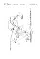
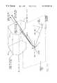
- FIG. 1Athere is shown an arrangement for communication to several satellites 2 for a typical Teleport or Mobile Satellite Service (MSS) site 1 .
- the site 1also referred to as a gateway, is a typical multi-satellite teleport having antennas 1 a in contact with several satellites 2 , each of which is connected to one or more gateways or served entities.
- the multiple antennas la connected to a single gateway 1may provide multiple satellite coverage, such as is proposed for Low Earth Orbit (LEO) Mobile Satellite Service (MSS) or Fixed Satellite Service (FSS).
- LEOLow Earth Orbit
- MSSMobile Satellite Service
- FSSFixed Satellite Service
- FIG. 1Billustrates the same site 1 with the addition of a spatial diversity site 1 b separated from the primary site by a distance D.
- the spatial diversity of antenna sitesprovides alternative signaling paths to a single one of the satellites 2 .
- the communicationscan be switched to the diversity site 1 b when atmospheric attenuation, due, for example, to a presence of a rain cell near the primary site 1 , exceeds a certain value at the primary site.
- a second approacheliminates the diversity site 1 b by placing the primary site 1 in a region, such as a desert, where rain is infrequent.
- the communications capabilityis enhanced by selecting the communications path or paths with the lowest attenuation, or by combining lowest attenuation paths, while avoiding paths which are heavily attenuated.
- This approachmaximizes communications signal strengths and reduces the amount of signal strength margin required. That is, instead of transmitting at a power level that is required to compensate for the heavily attenuated paths, and thus consuming a considerable amount of satellite power, a better approach is to avoid the heavily attenuated path or paths in favor of the less attenuated path or paths. In order to accomplish this technique it is necessary to make decisions based on observed amounts of path attenuation.
- An advantage provided by the teaching of this inventionis an ability to operate a satellite communications system so as to conserve system power.
- a further advantage provided by the teaching of this inventionis an ability to operate a satellite communications system so as to assign and allocate resources in accordance with a current model of RF signal path impairments between gateways, satellites, and user terminals, on a local or global scale.
- This inventionpertains particularly to satellite communications systems using GSO or NGSO satellites.
- This inventionemploys data derived from signals of various types to derive a model of atmospheric-related attenuation-inducing events so as to plan system resource allocation to minimize an amount of power required to close communication links between user terminals and the satellites.
- Disclosedare methods for modelling gateway to satellite links, as well as methods for modeling the user terminal to satellite links.
- This inventionavoids the necessity to employ diversity antenna sites, but does not preclude the use of such sites, by modeling atmospheric disturbances in real time by measurement, by predicting the “best” path to use, and by directing the antennas at the site to utilize a least faded path and/or to select alternate paths to avoid significant fading.
- the use of the invention at a diversity antenna siteimproves system performance.
- This inventionovercomes the problems inherent in the prior art by providing a direct measurement of severe path attenuation potential, without requiring a signal source either transmitted from the satellite or passed through the satellite.
- the use of the teaching of this inventionenables preplanning of the allocation of satellites and satellite resources by calculating a potential for signal path interference based on an external measurement of where rain attenuation may be located, and the real-time or approximately real-time tracking of rain cell activity within storm cells.
- a methodfor operating a satellite communications system of a type that includes a plurality of ground stations, a plurality of satellites, and a plurality of user terminals.
- the methodincludes the steps of, at a plurality of the gateways, generating a model of atmospheric-related attenuation-inducing structures and/or other propagation factors located within a coverage area of each of the gateways; transmitting data indicative of the generated model from each of the plurality of gateways to a gateway controller; and generating gateway commands at the gateway controller for preemptively allocating satellite communications system resources at least in accordance with the received data.
- FIGS. 1A and 1Billustrate a conventional single ground station or gateway site and a conventional spatial diversity site, respectively;
- FIGS. 2A-2Cillustrate relationships between various satellite constellations and their respective earth coverage areas
- FIG. 2Dis a simplified block diagram of a user terminal suitable for practicing this invention.
- FIG. 2Eis a simplified block diagram of a satellite suitable for practicing this invention.
- FIG. 2Fillustrates the effect of a rain cell on communication links between the user terminal and one of a plurality of non-geosynchronous satellites
- FIG. 3illustrates the use of primary and alternate paths between the user terminal and a gateway via a plurality of geosynchronous or non-geosynchronous satellites
- FIG. 4illustrates the effect of rain on the paths shown in FIG. 3;
- FIGS. 5A and 5Billustrate the effects of a remote storm and a local storm, respectively, on a gateway
- FIGS. 6A and 6Billustrate the varying amounts of attenuation resulting from light rain and heavy rain from a storm moving along a path relative to the gateway and satellites;
- FIG. 7is a simplified block diagram of a gateway site, in accordance with this invention, that is constructed to include a multiple satellite attenuation control system having a weather mapping system;
- FIGS. 8-11illustrate various aspects of the modeling of weather-related attenuation-inducing structures, such as rain cells, and the derivation of various three dimensional attenuation contours associated with these structures, in accordance with an aspect of this invention
- FIG. 12is a simplified block diagram of a satellite communication system in accordance with this invention having a plurality of spatially-separated gateways interconnected with a ground operations control center;
- FIGS. 13A-13Dare diagrams useful in explaining the amount of power required to close a communication link or links between a gateway and a user terminal via one or more satellites;
- FIGS. 14-17are useful in explaining an embodiment of this invention that employs user terminal signals for generating data for mapping and modelling weather-related attenuation-inducing structures, such as rain cells;
- FIG. 18illustrates the generation of a global model of rain attenuation in accordance with an aspect of this invention.
- a technique for anticipating and compensating for signal path impairments in either a NGSO satellite constellationsuch as a low earth orbit (LEO) satellite constellation, or a higher orbit constellation (Medium Earth Orbit (MEO) and/or GSO constellation(s)), so as to improve the resistance to environmental attenuation, such as that caused by rain.
- LEOlow earth orbit
- MEOMedium Earth Orbit
- GSO constellation(s)GSO constellation(s)
- the teaching of this inventionapplies to other propagation effects as well. These effects can be, but are not limited to, gaseous atmospheric absorption, ionospheric scintillation, Faraday rotation, variable atmospheric refraction, and rain depolarization.
- the teaching of this inventionapplies to RF signal attenuations induced by atmospheric-related effects, and to the modelling of such attenuation(s) and subsequent use of the model in compensating for the attenuation(s), in real or substantially real time, and/or in a predictive mode.
- the LEO (NGSO) satellite constellationincludes satellites 2 at an altitude of ⁇ 1400 km in eight circular planes offset by 45°, inclined at 52° relative to the equator with six satellites 10 a in each plane (which may be referred to as a Walker constellation).
- path diversityis employed to mitigate against local obstructions such as trees, buildings, and mountains.
- Path diversityrequires that a user terminal on the ground have a simultaneous view of two or more satellites at elevations above about 10° over the horizon.
- the LEO constellation described aboveprovides multiple satellite coverage over a large portion of the earth's surface.
- FIG. 2Aillustrates a general configuration of a satellite communications system 10 in accordance with the teaching of this invention.
- the satellite communications system 10includes a non-geosynchronous orbit (NGSO) satellite or a plurality of NGSO satellites 2 , which may be referred to collectively as a satellite constellation.
- This constellationmay be similar to that described in the U.S. Patents listed above as being incorporated by reference, although the teaching of this invention should not be read to be limited to only this particular type of LEO system.
- the NGSO satellites 2orbit the earth in the non-geosynchronous orbit 12 . It is not necessary that there be more than one satellite 2 , however, the preferred configuration contains many satellites.
- Each satellite 2has an associated earth coverage area 21 .
- FIG. 1illustrates a general configuration of a satellite communications system 10 in accordance with the teaching of this invention.
- the satellite communications system 10includes a non-geosynchronous orbit (NGSO) satellite or a plurality of NGSO satellites 2 , which may be
- GSOgeosynchronous
- a synchronous orbitis one in which the satellites 3 do not have apparent movement with respect to points on the earth.
- a given GSO satellite 3has an associated earth coverage area 22 which, because of the difference in altitude with respect to the non-GSO satellites 2 , is significantly larger than the coverage area 21 .
- the satellite 3it is not necessary for the satellite 3 to be in a GSO orbit, but in fact may be non-synchronous as well.
- the satellite 3could be in a medium earth orbit (MEO).
- MEOmedium earth orbit
- the satellites 3are at a greater altitude than the satellites 2 .
- the NGSO constellation or the GSO constellation, depending on which is used for a given satellite communication system,may be referred to as the space segment of the satellite communications system 10 .
- FIGS. 2B and 2Cfor illustrating two different embodiments of NGSO systems.
- constellation Athe coverage areas or regions 21 of the NGSO satellites 2 do not substantially overlap, any user terminals 5 within the coverage regions 21 do not compete for resources-from one NGSO satellite, and the power used is drawn from one satellite at a time for each user terminal.
- constellation BFIG. 2 C
- the coverage regions 21substantially overlap one another
- the user terminals 5 within the overlapping coverage zonescompete for resources from two or more NGSO satellites 2
- powermay be drawn from more than one satellite 2 at a time to support a single user terminal's communication links.
- the power cost of the links in both directionsis important.
- the user terminal 5in mobile and portable configurations, has a battery 5 a which supplies power to a digital section 5 b , including user terminal control processor, and an RF section 5 c , comprised of a transmitter, a receiver, and related RF signal handling components.
- the function of these various sectionsis to enable a satellite uplink 34 and a satellite downlink 33 to be established and maintained, via antenna 5 d , for transmitting and receiving voice and/or data communications.
- the NGSO satellite 2has battery 2 a which is charged from one or more solar panels 2 b through a power control unit 2 c .
- the operating power for a digital section 2 d and RF section 2 emust be supplied from the battery 2 a , via the power control unit 2 c , to establish and maintain the gateway uplink 31 , gateway downlink 32 , and the user terminal links 33 and 34 , through appropriate antennas 2 f .
- the digital section 2 dis assumed to include a suitable digital data processor and any required support circuits, such as a memory, demodulators, modulators, etc.
- the links 33 and 34are subject to various impairments, a variable amount of power is necessary to overcome the impairments.
- the specific nature of the impairmentsdepends on the nature of the operation, the type of system modulation being transmitted, and the slant range between the user terminal 5 and the satellite(s) 2 . It should be noted that in the NGSO satellite system the slant range is constantly varying as the satellites 2 move overhead.
- Some, but not all, of the various impairments that can be experiencedinclude impairments due to foliage absorption and diffraction, impairments due to building blockage or other obstructions in any frequency band, and, of most interest to this invention, impairments due to rain attenuation in bands above about 3 GHz.
- SS/CDMACode Division Multiple Access
- the power control system to keep the user terminals 5 at the same or at the minimum power level, as received at the satellite,is independent of the modulation scheme, impairment, or frequency band chosen.
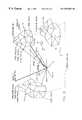
- FIG. 3for illustrating in greater detail the user terminals 5 , ground stations or gateways 6 and 7 , and their linking elements with the space segment.
- the user terminals 5bidirectionally communicate over RF links to a first NGSO satellite 2 or to a first GSO satellite 3 , collectively referred to hereinafter as satellite 50 a .
- the satellite 50 ais in orbit over the gateway to satellite feeder uplink 31 a and feeder downlink 32 a , and is in orbit over the satellite-to-user terminal downlink 33 a and user terminal-to-satellite uplink 34 a .
- These signalsmay be routed on the satellite 50 a to a gateway 6 within the coverage zone 21 of the NGSO satellite 2 , GW-NGSO 6 , or via the GSO satellite 3 to a gateway 7 within the coverage zone 22 of the GSO satellite 3 , GW-GSO 7 .
- the downlinks to GW-NGSO 6 or GW-GSO 7are routed to a single antenna or multiple antennas 1 a and thence to the gateway electronics 8 which in turn is connected externally to provide connectivity to an external network 9 , such as the public switched telephone network (PSTN) and/or to private networks.
- PSTNpublic switched telephone network
- the user terminals 5may be connected to themselves and not routed to a gateway.
- the gateway electronics 8may be connected to a restricted network associated with a governmental or corporate entity, and to which external access is not provided.
- FIG. 3there are at any given time one or more alternate satellites and alternate paths available to communicate to the user terminal 5 .
- These pathscan be utilized to increase the user terminal's immunity to fading caused by propagation effects, for example, fading caused by rain attenuation at frequencies above 5 GHz, which becomes more severe above 10 GHz.
- the employment of these alternate pathsis preferred.
- FIG. 3there are shown, by example, two alternate satellites 50 b and 50 c which the downlink 33 a and uplink 34 a signals to and from the user terminal 5 may be routed over, either simultaneously or individually.
- the alternate satellites 50 b and 50 cthus provide alternate signal paths 40 .
- These alternate pathscan be designated as 31 ( b or c ), 32 ( b or c ), 33 ( b or c ) and 34 ( b or c ) depending upon which satellite ( 50 a, b or c ) the path is directed through.
- the uplink signals 31 a, b or care directed toward the desired satellite 50 a , 50 b , 50 c , respectively, by the steerable antennas 1 a of the gateway 6 .
- the user terminal 5may also direct its uplink signal 34 through a particular one of the satellites 50 a , 50 b , and/or 50 c.
- any of these signal pathsmay be attenuated by atmospheric or other propagation effects, such as rain attenuation.
- the paths 31 a and 31 bare shown to be attenuated by rain attenuation due to a storm cloud 14 . While the entire area of the serving gateway 6 may be attenuated by rain, in general the rain attenuation will be maximum in certain directions.
- the various paths to the satellites 50 a , 50 b , and 50 c , and thence to the user terminal 5are illustrated, with rain attenuation on the gateway to satellite links 31 ( a, b , and c ) and 32 ( a, b , and c ). It can be seen that the attenuation can be more severe on one path than on another (e.g., path 31 a versus path 31 b ), and may be non-existent on yet another path (e.g., path 31 c ).
- the rain attenuationis caused by the signal passing through a “rain cell”.
- a rain cellin general conforms to cloudy areas or regions of dense clouded areas. It should be noted that “rain” per se at the earth's surface is not necessary.
- the “cell” 14 awill include varying levels of rain and moisture. The amount of attenuation on any path is a function of the elevation angle, the size of the rain cell, the amount of rainfall in mm/hr, and other effects such as scintillation caused by the rain, etc.
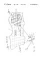
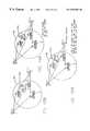
- FIG. 5Ashows a case where a storm 14 containing rain cells 14 a is remotely located with respect to the antenna site or gateway 6 .
- the path to satellite 50 ais attenuated, while the paths to satellites 50 b and 50 c are not affected by the storm.
- the path to the satellite 50 ais passing through a rain cell 14 a and is thus experiencing a maximum attenuation. Later in time the rain cell 14 a may have moved away and the path to satellite 50 a will experience less attenuation, but will still be attenuated relative to the paths to satellites 50 b and 50 c .
- FIG. 5Billustrates a case where the storm is directly over the gateway 6 . In this case all of the paths are attenuated. However, due to the motion of the rain cells 14 a the amount of attenuation will vary over time.
- FIG. 6 AA view of a typical storm event is shown in FIG. 6 A.
- the three antenna gateway site 6situated in a region with a large area of light rain and a single heavy rain cell 14 a .
- the satellites 50may move with respect to the ground coordinates of the site 6 , the storm 14 and the rain cell 14 a , or, as in the case of synchronous satellites, may be fixed in relative location.
- the received signal strength at the gateway antennas 1 avaries over time as, a function of the intensity and location of the storm 14 and the rain cell 14 a and the motion of the satellites in orbit.
- the path to satellite 50 cis clear and will remain clear for some time, depending on the speed of the storm front.
- the attenuation on this path, due to the storm 14is considered to be zero at this time.
- the path to satellite 50 bis attenuated during the same time frame by an amount consistent with light rain.
- the value of attenuation on the path to satellite 50 b(assuming the NGSO satellite case) varies over time due to satellite motion and elevation angle, which exposes a longer (or shorter) path through the rain, the movement of the storm 14 along the storm's path, and changes in rain intensity.
- the path to satellite 50 ais attenuated as well.
- the communications capabilityis enhanced by selecting the path or paths with the lowest attenuation, or by combining lowest attenuation paths, while avoiding paths which are heavily attenuated.
- This approachmaximizes communications signal strengths and reduces the amount of signal strength margin required. That is, instead of transmitting at a power level that is required to compensate for the heavily attenuated paths, and thus consuming a considerable amount of satellite power, the preferred approach is to avoid the heavily attenuated path or paths in favor of the less attenuated path or paths. In order to accomplish this technique it is necessary to make decisions based on observed amounts of path attenuation.
- FIG. 2 FThe system 10 attempts to link two NGSO satellites NGSO SAT- 1 and NGSO SAT- 2 with the user terminal 5 .
- the user terminal 5is transmitting a signal at a power P towards the two satellites simultaneously.
- the signals received at the user terminal 5 from the two satellitesare coherently combined in the user terminal 5 to form a single, composite signal.
- Reference in this regardcan be had to the above-referenced U.S. Pat. No. 5,233,626, issued Aug. 3, 1993, entitled “Repeater Diversity Spread Spectrum Communication System”, by S. A. Ames.
- a final destination for the signal transmitted to the two satellites from the user terminal 5may be the NGSO gateway 6 , the GSO gateway 7 (via the GSO satellite 3 ), or another user terminal 5 . In any case there is a certain received signal quality necessary at the NGSO satellites 2 to achieve a desired result at the final destination.
- the received power P(NGSO SAT- 1 ) at the NGSO SAT- 1is less than the desired level due to this attenuation (it being realized that the NGSO SAT- 1 is also simultaneously receiving uplinks from other user terminals 5 , which may or may not be impaired).
- the systemcan compensate for this link only (e.g., only the link 34 a ) while leaving all the other user terminals unaffected.
- energyis conserved and satellite cost and weight is minimized.
- the power from the user terminal 5 on the uplink 34 acan be directed preferentially towards the NGSO SAT- 2 , thus conserving battery and link power.
- FIG. 7illustrates a presently preferred embodiment of this invention.
- MSACSMultiple Satellite Attenuation Control System
- the first of these three componentsis a Weather Radar System (WRS) 101 , or any other suitable system capable of measuring, in azimuth and elevation, the location, size and shape of a rain cell and/or a rain storm).
- the second componentis an Attenuation Potential Signal Processing System (APSPS) 102 .
- APSPSAttenuation Potential Signal Processing System
- GACEGateway Antenna Control Electronics
- the systemoperates using any suitable weather radar system 101 to transmit bursts of RF energy in such a manner that received reflected radar signals from a rain storm 14 or rain cell 14 a within the storm can be characterized as to the location, distance, and, if possible, intensity from the WRS 101 .
- Suitable systemsare currently known to be used by air traffic control personnel at airports to model mathematically the intensity and location of clouds, and severe weather conditions in proximity to airports.
- the frequency of operation of the WRS 101may be, but is not necessarily, in the same band of frequencies as the communication signals to and from the satellites 2 or 3 (e.g., the satellite 50 a ). That is, the operating frequency of the WRS 101 may be in a different band of frequencies assigned to weather radars or other weather predicting equipment.
- the WRS 101 and related componentsare used as follows.
- the WRS 101transmits signals in a manner so as to survey an area around the gateway antenna site 6 .
- the WRS 101may use a conventional mechanical, rotating radar antenna system, a phased array antenna system, or any other suitable means for obtaining weather-related information from a region that contains the gateway 6 .
- the resulting datais passed to the APSPS 102 which constructs a mathematical model of the cloud(s) or storm and/or rain cell(s) based on the data provided by the WRS 101 .
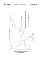
- FIG. 8illustrates a representation of the mathematical model derived by the APSPS 102 of the resultant attenuation data for several clouds, storm, or rain cells 14 a .
- This modelis then passed to the GACE unit 103 where information is calculated and decisions made on how to best optimize the communication capability to the user terminals 5 within the coverage area 6 a of the gateway 6 . For example, and referring briefly to FIG. 6A, a decision may be made to utilize path 50 c instead of paths 50 a and 50 b.
- a time historyis developed for ephemeral data of the satellite geometry to further predict and plan optimized satellite transmission to the user terminals 5 affected by the storm.
- a signal from the gateway 6is directed along path 31 a , 32 a towards satellite 50 a .
- the data from the WRS 101 for a given rain attenuation cloud or rain cellis processed by the APSPS 102 and a series of points are described using vector RC 1 ( 1 ) (angle 1 , angle 2 , and distance d 1 ); vector RC 1 ( 2 ) (angle 1 , angle 2 , d 2 ) and so on as RC 1 ( 1 ) RC 1 ( 2 ) RC 1 ( 3 ) . . . to RC 1 (n).
- layers or shells 15 of various attenuation strengths for each structuremay be constructed, as shown for only the structure RC 1 .
- Other shells for the other structures RC 2 to RC(m)may be constructed in a similar manner.
- Composite attenuation contours of various dB levelsare then constructed from the data available as shown in FIG. 10 . These contour level shells then become input data to the GACE unit 103 for use in decision making as to transmission strategies. It is clearly shown in the example of FIG. 10 that the signal directed towards a satellite which is visible through the “trough” in the contour pattern experiences considerably less attenuation than the signal 31 a , 31 b that passes through the region of severe attenuation due to the presence of one of the rain cells 14 a shown in FIGS. 6-9.
- the above-described atmospheric modellingis thus used to choose, in real time or approximately real time, a “best” communication path or paths in order to avoid severe attenuation on a single link.
- sequences of data stored in the APSPS 102are used to develop a historical plot of the track of the severe attenuation regions or rain cells 14 a .
- the historical plotsmay be used to predict not only future attenuation values, but can also be used in conjunction with other propagation effects, such as sky noise, noise from the quiet and active sun, and tropospheric effects versus elevation angle, for advance planning of which satellites to direct the communication links through.
- the planning carried out by the APSPS 102thus includes the movement of the NGSO satellites 2 with respect to the predicted movement of the rain attenuation contours.
- the attenuation contour data and its time historyis next passed to the GACE unit 103 which makes decisions, based on this data, as how to select available satellites to maximize the communications capability and utilization of the satellite resources.
- this informationmay be sent to a central location, such as a Ground Operations Control Center (GOCC) 300 over data lines 304 , 305 for further optimization of the overall satellite constellation power utilization.
- a central locationsuch as a Ground Operations Control Center (GOCC) 300 over data lines 304 , 305 for further optimization of the overall satellite constellation power utilization.
- GOCCGround Operations Control Center
- FIG. 12illustrates a configuration of multiple gateways (designated A-D) which are accessing a multiple satellite constellation ( 2 or 3 ) which is experiencing attenuation from multiple rain storm systems 14 and 14 ′.
- the storm systems 14 and 14 ′may be separated by hundreds or thousands of kilometers, depending on the placement of various ones of the gateways A-D.
- the storm system 14may be located over Brazil, while the storm system 14 ′ may be located over Indonesia.
- the gateways A-Bare shown connected to the GOCC 300 by the data lines 304 and 305 . Reference in this regard can also be had to FIG. 18 .
- the gateways A-Deach include a local Multiple Satellite Attenuation Control System (MSACS) 100 as shown in FIG. 7 .
- MSACSMultiple Satellite Attenuation Control System
- Each MSACS 100generates attenuation contour information which is processed and transmitted over data lines 304 to the GOCC 300 .
- the GOCC 300may be comprised of a plurality of regional sub-GOCCs interconnected to a master GOCC, or the functionality of the GOCC 300 may be integrated at one site.
- the attenuation datais input to a Constellation Resource Utilization Planning System (CRUPS) 302 which compiles the attenuation data and which provides preliminary gateway-by-gateway utilization information.
- CUPSConstellation Resource Utilization Planning System
- gateway Ais experiencing attenuation caused by storm system 14
- gateway Bis in the clear and has no attenuation at all.
- Gateway C and Dare experiencing varying amounts of attenuation with storm system 14 ′ (in this example gateway C less than gateway D).
- the CRUPS 302After the CRUPS 302 has obtained the attenuation data (which may be preprocessed by the originating gateways) it compares the communications needs of the individual gateways, and performs an optimization of the utilization of the entire constellation being accessed by the various gateways A-D. This optimization includes instantaneous direction in near real time as to optimization and future planning based on the time history data received from various ones of the MSACSs 100 .
- the decisions and future planning from the CRUPS 302is then input to a Constellation Control and Resource Allocation System (CCRAS) 301 which combines this information with other information derived from other sources, such as current and/or predicted communications traffic demand, etc.
- the CCRAS 301then issues commands via data lines 305 to the gateways A-D.
- CCRASConstellation Control and Resource Allocation System
- These commandsmay be actual antenna utilization commands, or more general instructions such as bandwidth, numbers of channels, and limits on satellite power that may be used. If these general commands are used then each gateway A-D utilizes its own information regarding storm system contours, in combination with the commands from the CCRAS 301 , to best optimize constellation power availability to satisfy the demand required by its associated user terminals 5 .
- the satellites over gateway Bare not experiencing any significant storm-related attenuation, whereas the satellites over gateways C and D are experiencing storm-related attenuation.
- the GOCC 300knows that the satellites over gateway B will be entering the coverage region of gateway C in X minutes. Based on the information received from the MSACS 100 of gateway D, the GOCC also knows that the storm 141 will most probably be increasing in strength, and will most probably be moving even further into the coverage region of gateway C, in X minutes. The GOCC 300 then plans for the increased power demand on the satellites as they enter the coverage region of gateway C.
- This planningcan include sending a command to the gateway B to select which visible satellites to load, or to only lightly load one particular one of the visible satellites with communications traffic, if demand permits, thereby reserving power on this satellite or satellites for the time that the satellite or satellites enters the coverage region of gateway C.
- This planningcan also include, for the case where the user terminals 5 can be assigned multiple satellite diversity, reducing the diversity level for the user terminals 5 being serviced by the gateway B to some minimal acceptable level, thereby further reducing the satellite loading and conserving satellite power. These various decisions also preferably take into account the expected communications traffic.
- the decision to reduce the diversity level of the user terminals 5 being serviced by the gateway Bmay be affected by the expected communications demand when the satellite(s) enter the coverage region of gateway C. If the expected demand in X minutes coincides with a peak communication demand period, then all available measures may be used to conserve satellite power, while if the expected demand in X minutes is expected to be minimal when the satellite(s) enter the coverage region of gateway C, then only minimal or even no power conservation measures may be commanded to the gateway B. It can thus be seen that the use of this invention enables preemptive communications link allocation and control based at least in part on predicted weather-related signal attenuation at a remote location. Although this example has used time expressed in minutes, in fact the decision process may be limited only by the decision time and the time required to obtain the necessary data, and can thus be sub-second in nature.
- an alternative to utilizing the weather radar data generated by the WRS 101is to use NASA downlink data from the Geostationary Orbiting Environment Satellite (GOES) and/or other satellite data from the National Oceanic and Atmospheric Agency (NOAA). These satellites produce severe weather observations, as well as cloud structures, and atmospheric sounding data which can be utilized to build weather-related models around a particular gateway site, much in the same manner as the weather radar data described above.
- GOESGeostationary Orbiting Environment Satellite
- NOAANational Oceanic and Atmospheric Agency
- Combinations of weather radar and satellite datacan also be used.
- FIGS. 13A-13Dfor illustrating a method of controlling the gateway power, which in turn drives the individual link input to each satellite 2 on a link-by-link basis, or as a summation of various links, or on a single link basis.
- a power P as transmitted from the gateway 6 towards user terminals 5is received on two paths via two different NGSO satellites (SAT- 1 and SAT- 2 ).
- SAT- 1 and SAT- 2the signals on each path may be at different strengths due to impairments.
- FIG. 13Aa typical user terminal 5 to gateway 6 link for satellite communications is shown.
- the gateway 6transmits a feeder link to the satellite (Sat- 1 ) at a power of P which the gateway 6 has determined necessary to close the link at a certain Eb/No at the user terminal 5 .
- This power Pmay include some margin to overcome link impairments.
- the reception of the feeder linkcauses SAT- 1 to generate a power P′ toward the user terminal 5 that is necessary to close the link, again at a certain Eb/No and with or without some additional margin.
- the power necessary for P′may be calculated or otherwise determined on the satellite itself for one or both link directions, for an onboard processing embodiment, and is not necessary to be known at the gateway 6 .
- the power P and P′may be split between the two satellites according to FIG. 13B as:
- P(feeder)is the power to close the link with only one satellite without impairments
- P′(user) is the power to close the link with only one satellite without impairments
- Xa power reduction factor on the link from gateway 6 to Sat- 1 ,
- Ya power reduction factor on the link from gateway 6 to Sat- 2 ,
- Aa power reduction factor on the link from Sat- 1 to user terminal 5 .
- Ba power reduction factor on the link from Sat- 2 to user terminal 5 .
- the user terminal 5receives the signals from the two (or more) satellites and coherently combines the signals to reduce the power required on each link to the minimum necessary.
- the values of X, Y, A, and Bare not necessarily the same.
- the strategy of satellite usage and values used for the power reduction factorsare defined such that the power of the transmitters is adjusted to continue to close the link with the minimum required power.
- the gateway 6may increase the power P on the feeder link to Sat- 1 , thus maintaining the overall link quality, in accordance with:
- the gateway 6may cause Sat- 1 to increase the power on the satellite-to-user link to compensate for the reduction in P(feeder) which is uncompensated, and thus reduced by the rain fade. This is, however, not an optimum solution due to the required increase in satellite power usage on Sat- 1 .
- the use of onboard processing of these signalsgives additional options here, and is included in the invention by reference.
- the gateway 6increases the power on the P(feeder) link, according to the first above-described option, until a gateway transmitter limitation is reached:
- z′a delta power factor which reduces Y, thereby increasing P(feeder Sat- 2 ) to compensate for the rain fade on the link to Sat- 1 .
- this approachcan be used up to a transmitter power limitation in the gateway 6 .
- the signals from the two satellitesare combined at the user terminal 5 so as to meet, by example, a specified energy per bit/noise ratio, a frame error rate, or a symbol error rate requirement.
- the gateway 6may abandon the link to Sat- 1 altogether, due to the severity of the rain fade on the link, thereby freeing up the frequency and allowing the use of this frequency for other purposes, such as by another gateway 6 ′ not experiencing the rain fade.
- the teaching of this inventioncan be implemented in at least two manners.
- a first approachassumes that the fading is reciprocal in the transmit and receive frequency bands of the user terminal 5 , thereby requiring only single link planning for the avoidance of heavy attenuation.
- a second approachindividually control the separate uplink and downlink in each respective frequency band, and thereby does not require any assumptions on the fading depth of the uplink 34 and the downlink 33 .
- a further approach to the modelling of the uplink 34 from the user terminal 5 to the satellitecan provide enhanced performance and precision of power control.
- This approachassumes that, in general, the link fading is not the same for the uplink 31 from the gateway 6 to the satellite and for the uplink 34 from the user terminal 5 to the satellite. This assumption is generally correct, in that the fade depth will not be the same due to differences in frequency separation, geometry, and rain cell location between the uplink 31 and uplink 34 .
- the fading of the gateway uplink 31simultaneously affects all of the user terminals 5 coupled to same satellite.
- fading due to the user terminal uplink 34 to the satelliteaffects only that user terminal, and normally not any of the other user terminals or the gateway to satellite link 31 , 32 .
- FIG. 14assumes that there are many user terminals 5 dispersed over the coverage region 6 a of the gateway 6 .
- the user terminals 5will access the satellite communication system 10 via many satellites at the same time, or may direct their signals via one or more satellites.
- FIG. 14it can be seen that some of the user terminal signals are faded by rain attenuation while others are not.
- user terminals 5 ′are affected by rain cell 14
- user terminals 5 ′′are affected by rain cell 14 a ′
- the remaining user terminal 5 links 33 , 34are not affected by these atmospheric sources of attenuation.
- the gateway link 31 , 32is not affected by the rain attenuation.
- a position locationis performed by the gateway 6 on a user terminal 5 when the user terminal 5 requests service.
- the locations of the various user terminals 5 in the service area 6are known in latitude and longitude. Alternatively the location may be known on a call-by-call basis for a user which is portable within a service area. Also known is the satellite ephemeral information, as well as the location of the gateway 6 . Therefore, it is possible to map the cloud formations and rain cells due to the attenuation observed on the user-satellite-gateway links, with the resultant fade depths and locations being mapped according to individual received signals from the satellites.
- the constellation of satellitesmay be used to enhance the fade contour data.
- FIGS. 15A and 15Bfor showing a two satellite system that extends the geometry of FIG. 14 . Since various user terminals 5 are simultaneously in clear view (or lesser, faded view) of some satellites, and are heavily faded with respect to other satellites, observing the overall fading pattern from the ensemble of user terminals 5 provides an enhanced view of the overall nature of the current fading phenomena.
- FIGS. 16A-16Dby observing this fading phenomena over time (T 1 -T 4 ) a history is developed much in the same manner as the description of the invention made above with respect to the MSACS 100 of FIG. 7 .
- a historical record of the movement of the rain cell 14 a ′ of FIG. 14is made as the rain cell 14 a ′ passes into and through the coverage area 6 a of the gateway 6 .
- a fading profile or contour map, of a type shown in FIG. 10can also be determined.
- the accuracy and resolution of the rain cell 14 a ′ contour map, and of the overall rain cell model,is enhanced as a function of the numbers of user terminals 5 that are active in the coverage region 6 a.
- the system planning of resource allocationcan be made based on only this model of the rain cell 14 a ′, or this model can be used in conjunction with and/or as an accuracy check on the data received from the WRS 101 and/or the satellite-based weather information.
- this rain cell datathe gateway 6 can issue instructions to the user terminals 5 as to transmitter power and/or preferred links, or the user terminals 5 can be instructed by information calculated onboard the satellites in the onboard processing case.
- FIG. 17illustrates an embodiment of this invention wherein there are multiple gateways operating such that user terminals can be linked to more than one gateway at a time via multiple satellites. This arrangement provides even further information on the location of the rain fades on both the user-to-satellite and the gateway-to-satellite links.
- FIG. 17illustrates a method wherein the gateway-to-satellite link can be used to receive additional information and communicate this information to other gateways.
- the gateway Bprovides secondary paths through Sat- 3 and Sat- 4 for user terminals A and B located in the service area 6 a of gateway A.
- the gateway Aalready is aware that the primary path between user terminal A and Sat- 2 is clear, that the primary path between user terminal B and Sat- 2 is faded, and that the paths between the gateway 6 and both user terminal A and User terminal B to Sat- 1 are clear.
- the gateway Btransmits additional information over the data network 304 to the gateway A (and optionally to the GOCC 300 ) as to the signal strengths of the secondary paths.
- gateway Bwill report that the secondary path is faded between user terminal A and Sat- 3 , and that the secondary path between user terminal B and Sat- 3 is clear, but that the secondary path to Sat- 4 is faded.
- gateway Aobtains from gateway B additional information regarding the size, elevation, and fading contour of the rain cell 14 a . Over a period of time the speed and direction of movement of the rain cell can also be determined.
- the gateway Amay observe a relatively constant link attenuation for its link to Sat- 2 and also for the primary link between user terminal B and Sat- 2 .
- the gateway Bwill report that the secondary link between user terminal B and Sat- 4 has experienced a reduction in fading as the rain cell 14 a clears the line-of sight between user terminal B and Sat- 4 . It is clear that this additional information is valuable to the gateway A, and/or to the GOCC 300 , in determining the characteristics of the rain cell 14 a and in predicting the future effect of this rain cell on the communications within the gateway coverage area.
- FIGS. 14-17employs the user terminal signals directly for generating data for mapping and modeling the weather-related attenuation-inducing structures, such as the rain cells 14 A. That is, this embodiment avoids the use of separate transmitters or beacons, such as conventional beacons located on the ground or on board the satellites.
- this attenuationis a combination of direct absorption by the rain drops, and an increase in noise in the channel that results from a depolarization of the polarized signal in the second channel on the same frequency.
- compensationscan be made for the rain-induced depolarization, such as by adjusting the rotation of-antenna feed mechanisms, or by adjusting the phase and amplitude of the receive or transmit antennas, so as to compensate for the loss due to depolarization of the signal.
- Various combinations of propagation effectsmay be separated by the methods of this invention and compensated independently.
- the WRS 101need not be co-located with the gateway 6 , but could be located at a remote location. In this case suitable transformations are made between the location of the WRS 101 and the location of the gateway to obtain the location of rain cells and the like relative to the gateway 6 . Furthermore, and for a gateway that services a large geographic region, weather-related data from a plurality of WRSs 101 that are located within the gateway's coverage region can be inputted and processed by the gateway 6 .
- teaching of this inventionis not limited for use only with radar-based or similar systems for obtaining weather-related data.
- data from a space-based lighting flash sensor system, and/or a terrestrial-based wind shear sensor systemmay be used to supplement the other weather-related data, assuming that the presence of lightning and/or wind shear are found to correlate with the presence of attenuation-inducing weather structures, such as rain cells.
- This inventioncan be used to develop a real-time or substantially real-time global model of RF signal attenuation, since the individual gateway (GW) information can be made available to the GOCC 300 , as shown in FIG. 18, via the ground data network that includes data lines 304 and 305 .
- a global model in this contextimplies that the model encompasses at least those regions of the earth wherein the majority of the earth's population resides.
Landscapes
- Engineering & Computer Science (AREA)
- Physics & Mathematics (AREA)
- Astronomy & Astrophysics (AREA)
- Aviation & Aerospace Engineering (AREA)
- General Physics & Mathematics (AREA)
- Computer Networks & Wireless Communication (AREA)
- Signal Processing (AREA)
- Radio Relay Systems (AREA)
- Monitoring And Testing Of Transmission In General (AREA)
- Mobile Radio Communication Systems (AREA)
Abstract
Description
Claims (29)
Priority Applications (8)
| Application Number | Priority Date | Filing Date | Title |
|---|---|---|---|
| US08/734,507US6587687B1 (en) | 1996-10-21 | 1996-10-21 | Multiple satellite fade attenuation control system |
| PCT/US1997/018022WO1998018214A1 (en) | 1996-10-21 | 1997-10-03 | Multiple satellite fade attenuation control system |
| AU48951/97AAU4895197A (en) | 1996-10-21 | 1997-10-03 | Multiple satellite fade attenuation control system |
| KR1019970053859AKR19980032991A (en) | 1996-10-21 | 1997-10-20 | Multi-Satellite Fading Attenuation Control System |
| CA002218668ACA2218668A1 (en) | 1996-10-21 | 1997-10-20 | Multiple satellite fade attenuation control system |
| IDP973482AID18596A (en) | 1996-10-21 | 1997-10-20 | DOUBLE SATELLITE ATTENUATION CONTROL SYSTEM |
| JP9288751AJPH10190550A (en) | 1996-10-21 | 1997-10-21 | Multiple satellite fade attenuation control system |
| EP97308335AEP0837569A3 (en) | 1996-10-21 | 1997-10-21 | Multiple satellite fade attenuation control system |
Applications Claiming Priority (1)
| Application Number | Priority Date | Filing Date | Title |
|---|---|---|---|
| US08/734,507US6587687B1 (en) | 1996-10-21 | 1996-10-21 | Multiple satellite fade attenuation control system |
Publications (1)
| Publication Number | Publication Date |
|---|---|
| US6587687B1true US6587687B1 (en) | 2003-07-01 |
Family
ID=24951970
Family Applications (1)
| Application Number | Title | Priority Date | Filing Date |
|---|---|---|---|
| US08/734,507Expired - LifetimeUS6587687B1 (en) | 1996-10-21 | 1996-10-21 | Multiple satellite fade attenuation control system |
Country Status (8)
| Country | Link |
|---|---|
| US (1) | US6587687B1 (en) |
| EP (1) | EP0837569A3 (en) |
| JP (1) | JPH10190550A (en) |
| KR (1) | KR19980032991A (en) |
| AU (1) | AU4895197A (en) |
| CA (1) | CA2218668A1 (en) |
| ID (1) | ID18596A (en) |
| WO (1) | WO1998018214A1 (en) |
Cited By (44)
| Publication number | Priority date | Publication date | Assignee | Title |
|---|---|---|---|---|
| US20020136191A1 (en)* | 2000-12-29 | 2002-09-26 | Draim John E. | System and method for satellite communications |
| US20020149811A1 (en)* | 2001-04-16 | 2002-10-17 | Lightpointe Communications, Inc. | Integrated environmental control and management system for free-space optical communication systems |
| US20030087606A1 (en)* | 2001-11-07 | 2003-05-08 | Dybdal Robert B. | Method of determining communication link quality employing beacon signals |
| US20030232596A1 (en)* | 2002-06-13 | 2003-12-18 | Snell William L. | Communication satellite in a satellite communication system with high aspect ratio cell arrangement and shared and allocable bandwidth |
| WO2004029794A1 (en)* | 2002-09-26 | 2004-04-08 | Viasat, Inc. | Soft diversity satellite gateway architecture |
| US20040066347A1 (en)* | 2002-06-25 | 2004-04-08 | Schiff Leonard Norman | Reducing service outages in a multibeam satellite system |
| US20040097192A1 (en)* | 2002-07-23 | 2004-05-20 | Schiff Leonard N. | Satellite-based programmable allocation of bandwidth for forward and return links |
| US6745028B1 (en)* | 1997-07-16 | 2004-06-01 | Ico Services Limited | Satellite mobile telephone cell departure prediction |
| US20040208591A1 (en)* | 2000-01-13 | 2004-10-21 | Lightpointe Communications, Inc. | Hybrid wireless optical and radio frequency communication link |
| US6813476B1 (en)* | 2000-11-13 | 2004-11-02 | Andrew Corporation | Method and system for compensating for atmospheric fading in a communications system |
| US6833805B1 (en)* | 2002-02-20 | 2004-12-21 | Georgia Tech Research Corporation | Method of compensating for atmospheric effects while using near horizon radar |
| US6853331B1 (en)* | 2002-02-20 | 2005-02-08 | Georgia Tech Research Corporation | Method of compensating for atmospheric effects while using near horizon radar utilizing a Doppler signal |
| US20050153655A1 (en)* | 1999-03-18 | 2005-07-14 | Hughes Electronics Corporation | Multi-platform wireless communication system for a variety of different user types |
| US20060014558A1 (en)* | 2004-07-13 | 2006-01-19 | Nec Corporation | Mobile communications system, method of controlling the transmission power in the system, and mobile station in the system |
| US20060060717A1 (en)* | 1999-09-10 | 2006-03-23 | David Castiel | Fixed satellite constellation system employing non-geostationary satellites in sub-geosynchronous elliptical orbits with common ground tracks |
| US7047029B1 (en)* | 2001-09-10 | 2006-05-16 | The Directv Group, Inc. | Adaptive transmission system |
| US20060154660A1 (en)* | 2003-09-02 | 2006-07-13 | Guy Waugh | Communication system and method |
| US7215954B1 (en)* | 1999-03-18 | 2007-05-08 | The Directv Group, Inc. | Resource allocation method for multi-platform communication system |
| US20090051589A1 (en)* | 2002-07-23 | 2009-02-26 | Qualcomm Incorporated | Satellite communication system constituted with primary and back-up multi-beam satellites |
| US20090069021A1 (en)* | 2007-09-11 | 2009-03-12 | The Directv Group, Inc. | Method and System for Monitoring and Switching Between a First Uplink Signal Processing Circuit and a Second Uplink Signal Processing Circuit |
| US20090070824A1 (en)* | 2007-09-11 | 2009-03-12 | The Directv Group, Inc. | Method and System for Monitoring and Switching Between Primary and Back-up Uplink Signal Processing Circuits in a Satellite Communication System |
| US20090067490A1 (en)* | 2007-09-11 | 2009-03-12 | The Directv Group, Inc. | Method and system for monitoring and switching between a primary encoder and a back-up encoder in a communication system |
| US20090070823A1 (en)* | 2007-09-11 | 2009-03-12 | The Directv Group, Inc. | Method and System for Monitoring and Switching Between a Primary and Diverse Site in a Satellite Communication System |
| US20090070827A1 (en)* | 2007-09-11 | 2009-03-12 | The Directv Group, Inc. | Method and System for Monitoring and Switching Between Primary and Back-up Receiver Decoder Circuits in a Communication System |
| US20090322567A1 (en)* | 2006-06-13 | 2009-12-31 | The Mitre Corporation | Flight restriction zone detection and avoidance |
| US20100017835A1 (en)* | 2008-07-18 | 2010-01-21 | Brian Wilson | Methods and apparatus for frequency agile band-pass filtering of broadcast signals |
| US7653349B1 (en) | 2003-06-18 | 2010-01-26 | The Directv Group, Inc. | Adaptive return link for two-way satellite communication systems |
| US20110140884A1 (en)* | 2009-10-23 | 2011-06-16 | Globalstar, Inc. | Simplex Personal and Asset Tracker |
| US20110159804A1 (en)* | 2009-12-30 | 2011-06-30 | Echostar Technologies Llc | Methods and apparatus for identifying signal degradation in a receiver |
| US20120155704A1 (en)* | 2010-12-17 | 2012-06-21 | Microsoft Corporation | Localized weather prediction through utilization of cameras |
| US20130273839A1 (en)* | 2012-04-11 | 2013-10-17 | The Boeing Company | Method and Apparatus for Providing a Communications Pathway with High Reliability |
| US8676121B1 (en) | 2011-05-31 | 2014-03-18 | Globalstar, Inc. | Method and apparatus for transmitting message from short-range wireless device over a satellite network |
| CN105763274A (en)* | 2016-04-06 | 2016-07-13 | 西安交通大学 | System and method of simulating wireless transmission environment in satellite mobile communication system |
| US9485010B1 (en) | 2001-09-10 | 2016-11-01 | The Directv Group, Inc. | Adaptive coding and modulation for spot beam satellite broadcast |
| US9538538B2 (en) | 2015-03-20 | 2017-01-03 | Qualcomm Incorporated | Satellite beam power backoff |
| US9585150B2 (en) | 2015-03-20 | 2017-02-28 | Qualcomm Incorporated | EPFD coverage for NGSO satellites |
| US10341063B2 (en) | 2015-04-22 | 2019-07-02 | Mitsubishi Electric Corporation | Satellite communication system and satellite communication ground apparatus |
| US10361771B2 (en)* | 2016-01-22 | 2019-07-23 | Viasat, Inc. | Determining an attenuation environment of a satellite communication terminal |
| US11032791B2 (en)* | 2014-01-22 | 2021-06-08 | Advantech Wireless Ltd. | Method and system for dynamically adjusting communication characteristics of satellite communication links based on weather nowcasting |
| CN113131989A (en)* | 2021-03-25 | 2021-07-16 | 中国科学院国家空间科学中心 | Design method for frequency spectrum sharing simulation time parameter of NGSO constellation system |
| US20230074318A1 (en)* | 2021-09-09 | 2023-03-09 | Hughes Network Systems, Llc | Switching radiofrequency chains |
| CN117375706A (en)* | 2023-12-04 | 2024-01-09 | 成都本原星通科技有限公司 | Low-orbit inter-satellite interference optimization method and system for receiving end |
| CN118778068A (en)* | 2024-07-29 | 2024-10-15 | 航天恒星科技有限公司 | Marine meteorological parameter inversion system based on space electromagnetic network |
| US12335025B2 (en) | 2021-09-09 | 2025-06-17 | Hughes Network Systems, Llc | Multi-band radiofrequency transceiver |
Families Citing this family (26)
| Publication number | Priority date | Publication date | Assignee | Title |
|---|---|---|---|---|
| US5905943A (en)* | 1997-04-29 | 1999-05-18 | Globalstar L.P. | System for generating and using global radio frequency maps |
| EP0954119A3 (en)* | 1998-04-29 | 1999-11-10 | Globalstar L.P. | A method of and system for generating a radio frequency map |
| US6321065B1 (en)* | 1998-10-30 | 2001-11-20 | Trw Inc. | Performance enhancement of open-loop power control for satellite communication systems |
| US6272340B1 (en)* | 1999-03-24 | 2001-08-07 | Trw Inc. | Load shedding method to enhance uplink margin with combined FDMA/TDMA uplinks |
| US6421528B1 (en)* | 1999-04-29 | 2002-07-16 | Hughes Electronics Corp. | Satellite transmission system with adaptive transmission loss compensation |
| US7043199B2 (en) | 2001-06-06 | 2006-05-09 | Hughes Network Systems Llc | Uplink power control system for satellite communication system employing on-board satellite processing and fade estimation |
| IL143820A0 (en)* | 2000-06-26 | 2002-04-21 | Hughes Electronics Corp | Uplink power control system for satellite communication system employing on-board satellite processing and fade estimation |
| EP1763154A1 (en)* | 2005-09-09 | 2007-03-14 | BAE Systems plc | Generation of propagation attenuation time series |
| US7773942B2 (en) | 2006-08-29 | 2010-08-10 | Wildblue Communications, Inc. | Redundant communication path for satellite communication data |
| KR100911161B1 (en)* | 2007-12-17 | 2009-08-06 | 한국항공우주연구원 | RF power limit level measuring aid for satellite S-band receiver |
| JP5423678B2 (en)* | 2008-08-05 | 2014-02-19 | 日本電気株式会社 | Route control system, route control device, route control method and program |
| US8730086B2 (en) | 2008-08-26 | 2014-05-20 | Viasat, Inc. | Weather detection using satellite communication signals |
| US8538328B2 (en) | 2008-09-11 | 2013-09-17 | Viasat, Inc. | Antenna and satellite alignment using beam projections |
| US8660142B2 (en) | 2008-09-25 | 2014-02-25 | Viasat, Inc. | Scheduling virtual bandwidth requests |
| US8411798B2 (en) | 2008-11-05 | 2013-04-02 | Viasat, Inc. | Reducing receiver power dissipation |
| US8000259B2 (en) | 2009-09-04 | 2011-08-16 | Viasat, Inc. | Distributed cache—adaptive multicast architecture for bandwidth reduction |
| KR101988553B1 (en)* | 2012-09-28 | 2019-06-13 | 한국전자통신연구원 | Apparatus and method of automatically managing of satellite broadcastings service |
| EP3188377A1 (en)* | 2015-12-29 | 2017-07-05 | Forsway Scandinavia AB | Hybrid satellite terrestrial broadband network |
| JP7183258B2 (en)* | 2017-09-11 | 2022-12-05 | ワールドビュー・サテライツ・リミテッド | Satellite system and method for dealing with rain fade |
| KR101976310B1 (en)* | 2018-01-06 | 2019-05-07 | 인제대학교 산학협력단 | judgment method of weather deterioration with radio wave attenuation |
| JP7296236B2 (en)* | 2019-03-29 | 2023-06-22 | Hapsモバイル株式会社 | Multi-feeder link configuration and its control in HAPS communication system |
| US10826598B1 (en) | 2019-07-10 | 2020-11-03 | Eagle Technology, Llc | Satellite communication system having mitigation action for rain fade and associated method |
| CN110504987B (en)* | 2019-07-30 | 2020-11-06 | 北京大学 | Resource allocation and access method in open wireless channel |
| LU101614B1 (en) | 2020-01-23 | 2021-08-09 | Databourg Systems Sarl S | Method and system for localizing satellite terminals |
| WO2023218556A1 (en)* | 2022-05-11 | 2023-11-16 | 日本電信電話株式会社 | Wireless communication method and wireless communication system |
| WO2024003996A1 (en)* | 2022-06-27 | 2024-01-04 | 日本電信電話株式会社 | Wireless communication system, wireless communication method, and wireless station |
Citations (38)
| Publication number | Priority date | Publication date | Assignee | Title |
|---|---|---|---|---|
| US4567485A (en) | 1981-11-16 | 1986-01-28 | Nippon Electric Co., Ltd. | Earth station transmission power control system for keeping an EIRP of down link signals constant irrespective of weather |
| US4752967A (en) | 1985-11-29 | 1988-06-21 | Tandem Computers Incorporated | Power control system for satellite communications |
| US4752925A (en) | 1984-11-13 | 1988-06-21 | Hughes Aircraft Company | Two-hop collocated satellite communications system |
| USRE32905E (en) | 1980-10-20 | 1989-04-11 | Equatorial Communications Company | Satellite communications system and apparatus |
| US4901307A (en) | 1986-10-17 | 1990-02-13 | Qualcomm, Inc. | Spread spectrum multiple access communication system using satellite or terrestrial repeaters |
| US4910792A (en) | 1986-08-14 | 1990-03-20 | Kokusai Denshin Denwa Co., Ltd. | Up-link power control in satellite communications system |
| WO1990013186A1 (en) | 1989-04-25 | 1990-11-01 | Geostar Corporation | Communication system employing multiple relay satellites operating on common downlink frequency |
| EP0421698A2 (en) | 1989-10-02 | 1991-04-10 | Motorola, Inc. | Method of predicting cell-to-cell hand-offs for a satellite cellular communications system |
| US5010317A (en) | 1989-11-30 | 1991-04-23 | Motorola, Inc. | Satellite based simulcast paging system |
| WO1991009473A1 (en) | 1989-12-14 | 1991-06-27 | Motorola, Inc. | Satellite based acknowledge-back paging system |
| US5073900A (en) | 1990-03-19 | 1991-12-17 | Mallinckrodt Albert J | Integrated cellular communications system |
| US5081703A (en) | 1990-06-27 | 1992-01-14 | Pactel Corporation | Satellite mobile communication system for rural service areas |
| US5095500A (en)* | 1989-12-07 | 1992-03-10 | Motorola, Inc. | Cellular radiotelephone diagnostic system |
| US5109390A (en) | 1989-11-07 | 1992-04-28 | Qualcomm Incorporated | Diversity receiver in a cdma cellular telephone system |
| US5119225A (en) | 1988-01-18 | 1992-06-02 | British Aerospace Public Limited Company | Multiple access communication system |
| US5126748A (en) | 1989-12-05 | 1992-06-30 | Qualcomm Incorporated | Dual satellite navigation system and method |
| US5138631A (en) | 1989-12-21 | 1992-08-11 | Gte Spacenet Corporation | Satellite communication network |
| WO1993009613A1 (en) | 1991-10-28 | 1993-05-13 | Calling Communications Corporation | Satellite communication system |
| US5216427A (en) | 1990-11-01 | 1993-06-01 | California Institute Of Technology | Land-mobile satellite communication system |
| US5233626A (en) | 1992-05-11 | 1993-08-03 | Space Systems/Loral Inc. | Repeater diversity spread spectrum communication system |
| WO1993015591A1 (en) | 1992-01-23 | 1993-08-05 | Nokia Telecommunications Oy | Method and system for planning a cellular radio network |
| US5239671A (en) | 1990-11-13 | 1993-08-24 | Pagemart, Inc. | Simulcast satellite paging system with provision for signal interruption |
| US5265119A (en) | 1989-11-07 | 1993-11-23 | Qualcomm Incorporated | Method and apparatus for controlling transmission power in a CDMA cellular mobile telephone system |
| US5285208A (en) | 1989-09-05 | 1994-02-08 | Motorola, Inc. | Power management system for a worldwide multiple satellite communications system |
| US5303286A (en) | 1991-03-29 | 1994-04-12 | Space Systems/Loral, Inc. | Wireless telephone/satellite roaming system |
| US5410728A (en) | 1988-10-28 | 1995-04-25 | Motorola, Inc. | Satellite cellular telephone and data communication system |
| EP0652649A2 (en) | 1993-11-10 | 1995-05-10 | Motorola, Inc. | Satellite cellular network resource management method and apparatus |
| US5422647A (en) | 1993-05-07 | 1995-06-06 | Space Systems/Loral, Inc. | Mobile communication satellite payload |
| US5433726A (en) | 1991-04-22 | 1995-07-18 | Trw Inc. | Medium-earth-altitude satellite-based cellular telecommunications system |
| US5439190A (en) | 1991-04-22 | 1995-08-08 | Trw Inc. | Medium-earth-altitude satellite-based cellular telecommunications |
| US5446756A (en) | 1990-03-19 | 1995-08-29 | Celsat America, Inc. | Integrated cellular communications system |
| US5448623A (en) | 1991-10-10 | 1995-09-05 | Space Systems/Loral, Inc. | Satellite telecommunications system using network coordinating gateways operative with a terrestrial communication system |
| US5511233A (en) | 1994-04-05 | 1996-04-23 | Celsat America, Inc. | System and method for mobile communications in coexistence with established communications systems |
| US5533011A (en) | 1990-12-07 | 1996-07-02 | Qualcomm Incorporated | Dual distributed antenna system |
| US5552798A (en) | 1994-08-23 | 1996-09-03 | Globalstar L.P. | Antenna for multipath satellite communication links |
| US5561837A (en)* | 1993-06-02 | 1996-10-01 | Alcatel Espace | Memory relay system for observation satellites |
| US5619525A (en) | 1995-06-06 | 1997-04-08 | Globalstar L.P. | Closed loop power control for low earth orbit satellite communications system |
| US5669063A (en)* | 1992-09-28 | 1997-09-16 | The United States Of America As Represented By The Secretary Of The Army | Method of establishing line of sight propagation |
- 1996
- 1996-10-21USUS08/734,507patent/US6587687B1/ennot_activeExpired - Lifetime
- 1997
- 1997-10-03WOPCT/US1997/018022patent/WO1998018214A1/enactiveSearch and Examination
- 1997-10-03AUAU48951/97Apatent/AU4895197A/ennot_activeAbandoned
- 1997-10-20KRKR1019970053859Apatent/KR19980032991A/ennot_activeWithdrawn
- 1997-10-20IDIDP973482Apatent/ID18596A/enunknown
- 1997-10-20CACA002218668Apatent/CA2218668A1/ennot_activeAbandoned
- 1997-10-21JPJP9288751Apatent/JPH10190550A/enactivePending
- 1997-10-21EPEP97308335Apatent/EP0837569A3/ennot_activeWithdrawn
Patent Citations (42)
| Publication number | Priority date | Publication date | Assignee | Title |
|---|---|---|---|---|
| USRE32905E (en) | 1980-10-20 | 1989-04-11 | Equatorial Communications Company | Satellite communications system and apparatus |
| USRE32905F1 (en) | 1980-10-20 | 1992-11-10 | Satellite communications system and apparatus | |
| US4567485A (en) | 1981-11-16 | 1986-01-28 | Nippon Electric Co., Ltd. | Earth station transmission power control system for keeping an EIRP of down link signals constant irrespective of weather |
| US4752925A (en) | 1984-11-13 | 1988-06-21 | Hughes Aircraft Company | Two-hop collocated satellite communications system |
| US4752967A (en) | 1985-11-29 | 1988-06-21 | Tandem Computers Incorporated | Power control system for satellite communications |
| US4910792A (en) | 1986-08-14 | 1990-03-20 | Kokusai Denshin Denwa Co., Ltd. | Up-link power control in satellite communications system |
| US4901307A (en) | 1986-10-17 | 1990-02-13 | Qualcomm, Inc. | Spread spectrum multiple access communication system using satellite or terrestrial repeaters |
| US5119225A (en) | 1988-01-18 | 1992-06-02 | British Aerospace Public Limited Company | Multiple access communication system |
| US5410728A (en) | 1988-10-28 | 1995-04-25 | Motorola, Inc. | Satellite cellular telephone and data communication system |
| WO1990013186A1 (en) | 1989-04-25 | 1990-11-01 | Geostar Corporation | Communication system employing multiple relay satellites operating on common downlink frequency |
| US5285208A (en) | 1989-09-05 | 1994-02-08 | Motorola, Inc. | Power management system for a worldwide multiple satellite communications system |
| EP0421698A2 (en) | 1989-10-02 | 1991-04-10 | Motorola, Inc. | Method of predicting cell-to-cell hand-offs for a satellite cellular communications system |
| US5265119A (en) | 1989-11-07 | 1993-11-23 | Qualcomm Incorporated | Method and apparatus for controlling transmission power in a CDMA cellular mobile telephone system |
| US5109390A (en) | 1989-11-07 | 1992-04-28 | Qualcomm Incorporated | Diversity receiver in a cdma cellular telephone system |
| US5010317A (en) | 1989-11-30 | 1991-04-23 | Motorola, Inc. | Satellite based simulcast paging system |
| US5126748A (en) | 1989-12-05 | 1992-06-30 | Qualcomm Incorporated | Dual satellite navigation system and method |
| US5095500A (en)* | 1989-12-07 | 1992-03-10 | Motorola, Inc. | Cellular radiotelephone diagnostic system |
| WO1991009473A1 (en) | 1989-12-14 | 1991-06-27 | Motorola, Inc. | Satellite based acknowledge-back paging system |
| US5138631A (en) | 1989-12-21 | 1992-08-11 | Gte Spacenet Corporation | Satellite communication network |
| US5446756A (en) | 1990-03-19 | 1995-08-29 | Celsat America, Inc. | Integrated cellular communications system |
| US5073900A (en) | 1990-03-19 | 1991-12-17 | Mallinckrodt Albert J | Integrated cellular communications system |
| US5339330A (en) | 1990-03-19 | 1994-08-16 | David D. Otten | Integrated cellular communications system |
| US5081703A (en) | 1990-06-27 | 1992-01-14 | Pactel Corporation | Satellite mobile communication system for rural service areas |
| US5216427A (en) | 1990-11-01 | 1993-06-01 | California Institute Of Technology | Land-mobile satellite communication system |
| US5239671A (en) | 1990-11-13 | 1993-08-24 | Pagemart, Inc. | Simulcast satellite paging system with provision for signal interruption |
| US5533011A (en) | 1990-12-07 | 1996-07-02 | Qualcomm Incorporated | Dual distributed antenna system |
| US5303286A (en) | 1991-03-29 | 1994-04-12 | Space Systems/Loral, Inc. | Wireless telephone/satellite roaming system |
| US5433726A (en) | 1991-04-22 | 1995-07-18 | Trw Inc. | Medium-earth-altitude satellite-based cellular telecommunications system |
| US5439190A (en) | 1991-04-22 | 1995-08-08 | Trw Inc. | Medium-earth-altitude satellite-based cellular telecommunications |
| US5551624A (en) | 1991-04-22 | 1996-09-03 | Trw Inc. | Medium-earth-altitude satellite-based cellular telecommunications |
| US5448623A (en) | 1991-10-10 | 1995-09-05 | Space Systems/Loral, Inc. | Satellite telecommunications system using network coordinating gateways operative with a terrestrial communication system |
| WO1993009613A1 (en) | 1991-10-28 | 1993-05-13 | Calling Communications Corporation | Satellite communication system |
| WO1993015591A1 (en) | 1992-01-23 | 1993-08-05 | Nokia Telecommunications Oy | Method and system for planning a cellular radio network |
| US5233626A (en) | 1992-05-11 | 1993-08-03 | Space Systems/Loral Inc. | Repeater diversity spread spectrum communication system |
| US5669063A (en)* | 1992-09-28 | 1997-09-16 | The United States Of America As Represented By The Secretary Of The Army | Method of establishing line of sight propagation |
| US5422647A (en) | 1993-05-07 | 1995-06-06 | Space Systems/Loral, Inc. | Mobile communication satellite payload |
| US5561837A (en)* | 1993-06-02 | 1996-10-01 | Alcatel Espace | Memory relay system for observation satellites |
| US5590395A (en) | 1993-11-10 | 1996-12-31 | Motorola, Inc. | Satellite cellular network resource management method and apparatus |
| EP0652649A2 (en) | 1993-11-10 | 1995-05-10 | Motorola, Inc. | Satellite cellular network resource management method and apparatus |
| US5511233A (en) | 1994-04-05 | 1996-04-23 | Celsat America, Inc. | System and method for mobile communications in coexistence with established communications systems |
| US5552798A (en) | 1994-08-23 | 1996-09-03 | Globalstar L.P. | Antenna for multipath satellite communication links |
| US5619525A (en) | 1995-06-06 | 1997-04-08 | Globalstar L.P. | Closed loop power control for low earth orbit satellite communications system |
Non-Patent Citations (20)
| Title |
|---|
| "A Communication Technique for Multipath Channels", R. Price, Proceedings of the IR, Mar. 1958, pp. 555-570. |
| "An Integrated Satellite-Cellular Land Mobile System for Europe", E. Del Re, University of Florence, Dept. of Electronics Engineering, italy, Sep. 21, 1989. |
| "Current and Future Mobile Satellite Communication Systems", S. Kato et al., IEICE Transactions, vol. E 74, No. 8 Aug. 1991, pp. 2201-2210. |
| "Digital Network Oriented Mobile Radio Satellite System as an Integrated Part of the GSM Cellular Radio System in Europe", P. Dondl, Deutsch BUndespost/Fernmeldetechniches Zentralmt/Darmstadt, Fed. Rep. Germ. Sep. 21, 1989. |
| "Increased Capacity Using CDMA for Mobile Satellite Communication", K. Gilhousen et al., IEEE Journal on Selected Areas in Communications, vol. 8, No. 4, May 1990, pp. 503-514. |
| "Iridium: Key to Worldwide Celluar Communications", J. Foley, Telecommunication, Oct. 1991, pp. 23-28. |
| "Software Implementation of a PN Spread Spectrum Receiver to Accommodate Dynamics", C. Cahn et al., IEEE Trans. on Comm., vol. COM-25, No. 8, Aug. 1977. |
| "The IridiumTM1 System-A Revolutionary Satellite Communications System Developed with Innovative Applications of Technology", D. Sterling et al., IEEE, MILCOM 1991, Nov. 4-7. |
| "The OmniTRACSR Mobile Satellite Communicatons and Positioning System", E. Tiedemann, Jr. et al., Vehicle Electronics in the 90's: Proceedings of the In'l. Congress on Transporation Electronics, 10/90. |
| Application of Ellipsat Corporation ELLIPSAT for the Authority to Construct ELLIPSORI An Elliptical Orbit Satellite System, before the FCC, Washington, D.C. 20554, Nov. 2, 1990, pp. 5-34. |
| Application of Loral Cellular Systems, Corp., Globalstar Mobile Communications Wherever You Are, before the FCC, Washington, D.C. Jun. 3, 1991, pp. 94-187. |
| Application of Motorola Satellite Communications, Inc. for IRIDIUM A Low Earth Orbit Mobile Satellite System before the FCC, Washington, D.C. Dec. 1990, pp. 49-96. |
| Application of TRW Inc. for Authority to Construct a New Communications Satellite System Odysseysm before the FCC, Washington, D.C. 20554, May 31, 1991 pp. 33-51. |
| Before the FCC, Washington, D.C. 20554, ARIES CONSTELLATION Low Earth Orbit Satellite System Proposal of Constellation Communications, Inc. Jun. 3, 1991, Appendix A, B, and C. |
| Earth-Satellite Propagation Research by F. Davarian in IEEE Communications Magazine, Apr. 1994 No. 4, pp. 74-79. |
| Fade Measurements at 20 GHz Using MAYAK and OLYMPUS Satellites, by Ahmed et al., University of SUrrey, U.K. pub Nov. 2, 1993 pp. 269-274. |
| Joint On-Board Resource Sharing and Hierarchical Modulation Scheme for Satellite Communication by M. Morimoto etal., Osaka University, Japan pp. 1662-1666 pub. Nov. 14, 1995. |
| Petition of American Mobile Satellite Corporation Beford the FCC, Washington, DC 20554, dated Jun. 3, 1991, pp 1-15. |
| Software Package for the Performance Evaluation of Satellite Communication Systems with Adaptive Allocation of On-Board Common Resources by F. Barbaliscia et al., in IEEE Transactions on Communications, vol. 40, No. 6, Jun. 1992 pp. 1003-1005. |
| US 5,415,368, 5/1995, Horstein et al. (withdrawn) |
Cited By (83)
| Publication number | Priority date | Publication date | Assignee | Title |
|---|---|---|---|---|
| US6745028B1 (en)* | 1997-07-16 | 2004-06-01 | Ico Services Limited | Satellite mobile telephone cell departure prediction |
| US7474873B2 (en) | 1997-07-16 | 2009-01-06 | Ico Services Limited | Satellite mobile telephone cell departure prediction |
| US7260391B2 (en) | 1997-07-16 | 2007-08-21 | Ico Services Limited | Satellite mobile telephone cell departure prediction |
| US7218932B2 (en) | 1997-07-16 | 2007-05-15 | Ico Services Ltd. | Satellite mobile telephone cell departure prediction |
| US20050250558A1 (en)* | 1997-07-16 | 2005-11-10 | Ico Services Limited | Satellite mobile telephone cell departure prediction |
| US20050250490A1 (en)* | 1997-07-16 | 2005-11-10 | Ico Services Limited | Satellite mobile telephone cell departure prediction |
| US20040224632A1 (en)* | 1997-07-16 | 2004-11-11 | Ico Services Limited | Satellite mobile telephone cell departure prediction |
| US7215954B1 (en)* | 1999-03-18 | 2007-05-08 | The Directv Group, Inc. | Resource allocation method for multi-platform communication system |
| US20050153655A1 (en)* | 1999-03-18 | 2005-07-14 | Hughes Electronics Corporation | Multi-platform wireless communication system for a variety of different user types |
| US8223733B2 (en) | 1999-03-18 | 2012-07-17 | The Directv Group, Inc. | Multi-platform wireless communication system for a variety of different user types |
| US20060060717A1 (en)* | 1999-09-10 | 2006-03-23 | David Castiel | Fixed satellite constellation system employing non-geostationary satellites in sub-geosynchronous elliptical orbits with common ground tracks |
| US7110678B2 (en) | 2000-01-13 | 2006-09-19 | Lightpointe Communications, Inc. | Hybrid wireless optical and radio frequency communication link |
| US20040208591A1 (en)* | 2000-01-13 | 2004-10-21 | Lightpointe Communications, Inc. | Hybrid wireless optical and radio frequency communication link |
| US6813476B1 (en)* | 2000-11-13 | 2004-11-02 | Andrew Corporation | Method and system for compensating for atmospheric fading in a communications system |
| US20020136191A1 (en)* | 2000-12-29 | 2002-09-26 | Draim John E. | System and method for satellite communications |
| US6889009B2 (en)* | 2001-04-16 | 2005-05-03 | Lightpointe Communications, Inc. | Integrated environmental control and management system for free-space optical communication systems |
| US20020149811A1 (en)* | 2001-04-16 | 2002-10-17 | Lightpointe Communications, Inc. | Integrated environmental control and management system for free-space optical communication systems |
| US9485010B1 (en) | 2001-09-10 | 2016-11-01 | The Directv Group, Inc. | Adaptive coding and modulation for spot beam satellite broadcast |
| US7047029B1 (en)* | 2001-09-10 | 2006-05-16 | The Directv Group, Inc. | Adaptive transmission system |
| US20030087606A1 (en)* | 2001-11-07 | 2003-05-08 | Dybdal Robert B. | Method of determining communication link quality employing beacon signals |
| US7373105B2 (en)* | 2001-11-07 | 2008-05-13 | The Aerospace Corporation | Method of determining communication link quality employing beacon signals |
| US6833805B1 (en)* | 2002-02-20 | 2004-12-21 | Georgia Tech Research Corporation | Method of compensating for atmospheric effects while using near horizon radar |
| US6853331B1 (en)* | 2002-02-20 | 2005-02-08 | Georgia Tech Research Corporation | Method of compensating for atmospheric effects while using near horizon radar utilizing a Doppler signal |
| US6947740B2 (en)* | 2002-06-13 | 2005-09-20 | Spacecode Llc | Communication satellite in a satellite communication system with high aspect ratio cell arrangement and shared and allocable bandwidth |
| US20030232596A1 (en)* | 2002-06-13 | 2003-12-18 | Snell William L. | Communication satellite in a satellite communication system with high aspect ratio cell arrangement and shared and allocable bandwidth |
| US20050272370A1 (en)* | 2002-06-25 | 2005-12-08 | Schiff Leonard N | Reducing service outages in a multibeam satellite system |
| US20040066347A1 (en)* | 2002-06-25 | 2004-04-08 | Schiff Leonard Norman | Reducing service outages in a multibeam satellite system |
| US7599657B2 (en)* | 2002-06-25 | 2009-10-06 | Qualcomm Incorporated | Reducing service outages in a multibeam satellite system |
| US20090051589A1 (en)* | 2002-07-23 | 2009-02-26 | Qualcomm Incorporated | Satellite communication system constituted with primary and back-up multi-beam satellites |
| US8358971B2 (en)* | 2002-07-23 | 2013-01-22 | Qualcomm Incorporated | Satellite-based programmable allocation of bandwidth for forward and return links |
| US8744344B2 (en) | 2002-07-23 | 2014-06-03 | Qualcomm Incorporated | Satellite communication system constituted with primary and back-up multi-beam satellites |
| US20040097192A1 (en)* | 2002-07-23 | 2004-05-20 | Schiff Leonard N. | Satellite-based programmable allocation of bandwidth for forward and return links |
| US7584297B1 (en)* | 2002-09-26 | 2009-09-01 | Viasat, Inc. | Soft diversity satellite gateway architecture |
| WO2004029794A1 (en)* | 2002-09-26 | 2004-04-08 | Viasat, Inc. | Soft diversity satellite gateway architecture |
| US7653349B1 (en) | 2003-06-18 | 2010-01-26 | The Directv Group, Inc. | Adaptive return link for two-way satellite communication systems |
| US7783288B2 (en)* | 2003-09-02 | 2010-08-24 | Slieve Mish Inventions Limited | Mobile network base station controller comprising a central gateway and a physically separate remote gateway which communicate via a remote link |
| US20060154660A1 (en)* | 2003-09-02 | 2006-07-13 | Guy Waugh | Communication system and method |
| US7603135B2 (en)* | 2004-07-13 | 2009-10-13 | Nec Corporation | Mobile communications system, method of controlling the transmission power in the system, and mobile station in the system |
| US20060014558A1 (en)* | 2004-07-13 | 2006-01-19 | Nec Corporation | Mobile communications system, method of controlling the transmission power in the system, and mobile station in the system |
| US7957853B2 (en) | 2006-06-13 | 2011-06-07 | The Mitre Corporation | Flight restriction zone detection and avoidance |
| US20090322567A1 (en)* | 2006-06-13 | 2009-12-31 | The Mitre Corporation | Flight restriction zone detection and avoidance |
| US8792336B2 (en) | 2007-09-11 | 2014-07-29 | The Directv Group, Inc. | Method and system for monitoring and switching between primary and back-up receiver decoder circuits in a communication system |
| US8424044B2 (en) | 2007-09-11 | 2013-04-16 | The Directv Group, Inc. | Method and system for monitoring and switching between a primary encoder and a back-up encoder in a communication system |
| US20090070823A1 (en)* | 2007-09-11 | 2009-03-12 | The Directv Group, Inc. | Method and System for Monitoring and Switching Between a Primary and Diverse Site in a Satellite Communication System |
| US8804499B2 (en)* | 2007-09-11 | 2014-08-12 | The Directv Group, Inc. | Method and system for monitoring and switching between a first uplink signal processing circuit and a secondary uplink signal processing circuit |
| US8165060B2 (en) | 2007-09-11 | 2012-04-24 | The Directv Group, Inc. | Method and system for monitoring and switching between primary and back-up uplink signal processing circuits in a satellite communication system |
| US20090067490A1 (en)* | 2007-09-11 | 2009-03-12 | The Directv Group, Inc. | Method and system for monitoring and switching between a primary encoder and a back-up encoder in a communication system |
| US20090070824A1 (en)* | 2007-09-11 | 2009-03-12 | The Directv Group, Inc. | Method and System for Monitoring and Switching Between Primary and Back-up Uplink Signal Processing Circuits in a Satellite Communication System |
| US20090069021A1 (en)* | 2007-09-11 | 2009-03-12 | The Directv Group, Inc. | Method and System for Monitoring and Switching Between a First Uplink Signal Processing Circuit and a Second Uplink Signal Processing Circuit |
| US8472871B2 (en) | 2007-09-11 | 2013-06-25 | The Directv Group, Inc. | Method and system for monitoring and switching between a primary and diverse site in a satellite communication system |
| US20090070827A1 (en)* | 2007-09-11 | 2009-03-12 | The Directv Group, Inc. | Method and System for Monitoring and Switching Between Primary and Back-up Receiver Decoder Circuits in a Communication System |
| US8370890B2 (en) | 2008-07-18 | 2013-02-05 | At&T Intellectual Property I, L.P. | Methods and apparatus for frequency agile band-pass filtering of broadcast signals |
| US8549577B2 (en) | 2008-07-18 | 2013-10-01 | At&T Intellectual Property I, L.P. | Methods and apparatus for frequency agile band-pass filtering of broadcast signals |
| US20100017835A1 (en)* | 2008-07-18 | 2010-01-21 | Brian Wilson | Methods and apparatus for frequency agile band-pass filtering of broadcast signals |
| US8604925B2 (en) | 2009-10-23 | 2013-12-10 | Globalstar, Inc. | Simplex personal and asset tracker |
| US20110140884A1 (en)* | 2009-10-23 | 2011-06-16 | Globalstar, Inc. | Simplex Personal and Asset Tracker |
| US8626097B2 (en)* | 2009-12-30 | 2014-01-07 | Echostar Technologies L.L.C. | Methods and apparatus for identifying signal degradation in a receiver |
| US20110159804A1 (en)* | 2009-12-30 | 2011-06-30 | Echostar Technologies Llc | Methods and apparatus for identifying signal degradation in a receiver |
| US10928845B2 (en) | 2010-12-17 | 2021-02-23 | Microsoft Technology Licensing, Llc | Scheduling a computational task for performance by a server computing device in a data center |
| US9069103B2 (en)* | 2010-12-17 | 2015-06-30 | Microsoft Technology Licensing, Llc | Localized weather prediction through utilization of cameras |
| US20120155704A1 (en)* | 2010-12-17 | 2012-06-21 | Microsoft Corporation | Localized weather prediction through utilization of cameras |
| US10126771B2 (en) | 2010-12-17 | 2018-11-13 | Microsoft Technology Licensing, Llc | Localized weather prediction through utilization of cameras |
| US8676121B1 (en) | 2011-05-31 | 2014-03-18 | Globalstar, Inc. | Method and apparatus for transmitting message from short-range wireless device over a satellite network |
| US9467364B2 (en)* | 2012-04-11 | 2016-10-11 | The Boeing Company | Method and apparatus for providing a communications pathway with high reliability |
| US20130273839A1 (en)* | 2012-04-11 | 2013-10-17 | The Boeing Company | Method and Apparatus for Providing a Communications Pathway with High Reliability |
| US11032791B2 (en)* | 2014-01-22 | 2021-06-08 | Advantech Wireless Ltd. | Method and system for dynamically adjusting communication characteristics of satellite communication links based on weather nowcasting |
| US9538538B2 (en) | 2015-03-20 | 2017-01-03 | Qualcomm Incorporated | Satellite beam power backoff |
| US9585150B2 (en) | 2015-03-20 | 2017-02-28 | Qualcomm Incorporated | EPFD coverage for NGSO satellites |
| US9730227B2 (en) | 2015-03-20 | 2017-08-08 | Qualcomm Incorporated | Dynamic frequency allocation of satellite beams |
| US10341063B2 (en) | 2015-04-22 | 2019-07-02 | Mitsubishi Electric Corporation | Satellite communication system and satellite communication ground apparatus |
| US10594386B2 (en) | 2016-01-22 | 2020-03-17 | Viasat, Inc. | Determining an attenuation environment of a satellite communication terminal |
| US10361771B2 (en)* | 2016-01-22 | 2019-07-23 | Viasat, Inc. | Determining an attenuation environment of a satellite communication terminal |
| US12113605B2 (en)* | 2016-01-22 | 2024-10-08 | Viasat, Inc. | Determining an attenuation environment of a satellite communication terminal |
| CN105763274B (en)* | 2016-04-06 | 2018-04-17 | 西安交通大学 | The analogue system and method for wireless transmission environments in a kind of satellite mobile communication system |
| CN105763274A (en)* | 2016-04-06 | 2016-07-13 | 西安交通大学 | System and method of simulating wireless transmission environment in satellite mobile communication system |
| CN113131989A (en)* | 2021-03-25 | 2021-07-16 | 中国科学院国家空间科学中心 | Design method for frequency spectrum sharing simulation time parameter of NGSO constellation system |
| CN113131989B (en)* | 2021-03-25 | 2021-12-28 | 中国科学院国家空间科学中心 | A Design Method of Spectrum Sharing Simulation Time Parameters for NGSO Constellation System |
| US20230074318A1 (en)* | 2021-09-09 | 2023-03-09 | Hughes Network Systems, Llc | Switching radiofrequency chains |
| US12212403B2 (en)* | 2021-09-09 | 2025-01-28 | Hughes Network Systems, Llc | Switching radiofrequency chains |
| US12335025B2 (en) | 2021-09-09 | 2025-06-17 | Hughes Network Systems, Llc | Multi-band radiofrequency transceiver |
| CN117375706A (en)* | 2023-12-04 | 2024-01-09 | 成都本原星通科技有限公司 | Low-orbit inter-satellite interference optimization method and system for receiving end |
| CN117375706B (en)* | 2023-12-04 | 2024-03-12 | 成都本原星通科技有限公司 | Low-orbit inter-satellite interference optimization method and system for receiving end |
| CN118778068A (en)* | 2024-07-29 | 2024-10-15 | 航天恒星科技有限公司 | Marine meteorological parameter inversion system based on space electromagnetic network |
Also Published As
| Publication number | Publication date |
|---|---|
| JPH10190550A (en) | 1998-07-21 |
| AU4895197A (en) | 1998-05-15 |
| KR19980032991A (en) | 1998-07-25 |
| WO1998018214A1 (en) | 1998-04-30 |
| CA2218668A1 (en) | 1998-04-21 |
| ID18596A (en) | 1998-04-23 |
| EP0837569A2 (en) | 1998-04-22 |
| EP0837569A3 (en) | 1999-08-25 |
Similar Documents
| Publication | Publication Date | Title |
|---|---|---|
| US6587687B1 (en) | Multiple satellite fade attenuation control system | |
| US8442519B2 (en) | Spectrum sharing between an aircraft-based air-to-ground communication system and existing geostationary satellite services | |
| US5956619A (en) | Satellite controlled power control for personal communication user terminals | |
| US5867109A (en) | Satellite repeater diversity resource management system | |
| US6011951A (en) | Technique for sharing radio frequency spectrum in multiple satellite communication systems | |
| US9871577B2 (en) | Global communication network | |
| US6104911A (en) | Communication system with satellite diversity and method of operation thereof | |
| US20140128059A1 (en) | Device and method for optimizing the ground coverage of a hybrid space system | |
| JPH10502223A (en) | Cost effective communication system using mobile satellites synchronized from the earth | |
| US5995841A (en) | Technique for sharing radio frequency spectrum in multiple satellite communication systems | |
| Dey et al. | An approach to calculate the performance and link budget of leo satellite (iridium) for communication operated at frequency range (1650–1550) mhz | |
| Amatetti et al. | Non‐terrestrial Network Support for Massive Machine‐Type Communication: Architectural and Radio Channel Model Considerations | |
| Smith III | The orbit/spectrum resource and the technology of satellite telecommunications: an overview | |
| Andreadis et al. | Latency Analysis for Satellite IoT in Remote Areas | |
| SUMMERS et al. | Aries-Global communication through a constellation of low earth orbit satellites | |
| CN1187721A (en) | Multiple satellite fade attenuation control system | |
| HK1242104A1 (en) | Spectrum sharing between an aircraft-based air-to-ground communication system and existing geostationary satellite services | |
| Cornara et al. | Dial-A-Satellite: First Results from a Feasibility Study | |
| Holzbock | Mobile multimedia service provisioning with collective terminals in broadband satellite networks. An approach for systematic satellite communication system design for service provisioning to collective mobile terminals including: mobile satellite channel modelling, antenna pointing, hierarchical multi-service dimensioning and aeronautical system dimensioning. | |
| Lewis | Factors involved in determining the performance of digital satellite links | |
| Olsson | Satellite Personal Communication Services (S-PCS) | |
| Ge | Link performance analysis of disaster monitoring system | |
| MXPA97009493A (en) | System of management of satellite energy diversity resources | |
| Hovstad et al. | Future systems for mobile satellite communications | |
| HK1010435A (en) | Satellite repeater diversity resource management system |
Legal Events
| Date | Code | Title | Description |
|---|---|---|---|
| AS | Assignment | Owner name:GLOBALSTAR L.P., CALIFORNIA Free format text:ASSIGNMENT OF ASSIGNORS INTEREST;ASSIGNOR:WIEDEMAN, ROBERT A.;REEL/FRAME:008263/0929 Effective date:19961018 | |
| STCF | Information on status: patent grant | Free format text:PATENTED CASE | |
| FEPP | Fee payment procedure | Free format text:PAYOR NUMBER ASSIGNED (ORIGINAL EVENT CODE: ASPN); ENTITY STATUS OF PATENT OWNER: LARGE ENTITY | |
| AS | Assignment | Owner name:GLOBALSTAR LLC, CALIFORNIA Free format text:ASSIGNMENT OF ASSIGNORS INTEREST;ASSIGNOR:GLOBALSTAR L.P.;REEL/FRAME:017154/0960 Effective date:20051222 | |
| AS | Assignment | Owner name:GLOBALSTAR, INC.,CALIFORNIA Free format text:ASSIGNMENT OF ASSIGNORS INTEREST;ASSIGNOR:GLOBALSTAR LLC;REEL/FRAME:017870/0117 Effective date:20060623 Owner name:GLOBALSTAR, INC., CALIFORNIA Free format text:ASSIGNMENT OF ASSIGNORS INTEREST;ASSIGNOR:GLOBALSTAR LLC;REEL/FRAME:017870/0117 Effective date:20060623 | |
| AS | Assignment | Owner name:WACHOVIA INVESTMENT HOLDINGS, LLC,NORTH CAROLINA Free format text:PATENT SECURITY AGREEMENT;ASSIGNOR:GLOBALSTAR, INC.;REEL/FRAME:017982/0148 Effective date:20060421 Owner name:WACHOVIA INVESTMENT HOLDINGS, LLC, NORTH CAROLINA Free format text:PATENT SECURITY AGREEMENT;ASSIGNOR:GLOBALSTAR, INC.;REEL/FRAME:017982/0148 Effective date:20060421 | |
| FPAY | Fee payment | Year of fee payment:4 | |
| AS | Assignment | Owner name:THERMO FUNDING COMPANY LLC, COLORADO Free format text:ASSIGNMENT OF CREDIT AGREEMENT;ASSIGNOR:WACHOVIA INVESTMENT HOLDINGS, LLC;REEL/FRAME:020353/0683 Effective date:20071217 Owner name:THERMO FUNDING COMPANY LLC,COLORADO Free format text:ASSIGNMENT OF CREDIT AGREEMENT;ASSIGNOR:WACHOVIA INVESTMENT HOLDINGS, LLC;REEL/FRAME:020353/0683 Effective date:20071217 | |
| AS | Assignment | Owner name:GLOBALSTAR, INC., CALIFORNIA Free format text:RELEASE BY SECURED PARTY;ASSIGNOR:THERMO FUNDING COMPANY LLC;REEL/FRAME:022856/0094 Effective date:20090622 Owner name:GLOBALSTAR, INC.,CALIFORNIA Free format text:RELEASE BY SECURED PARTY;ASSIGNOR:THERMO FUNDING COMPANY LLC;REEL/FRAME:022856/0094 Effective date:20090622 | |
| AS | Assignment | Owner name:BNP PARIBAS, FRANCE Free format text:GRANT OF SECURITY INTEREST;ASSIGNOR:GLOBALSTAR, INC.;REEL/FRAME:022856/0308 Effective date:20090622 Owner name:BNP PARIBAS,FRANCE Free format text:GRANT OF SECURITY INTEREST;ASSIGNOR:GLOBALSTAR, INC.;REEL/FRAME:022856/0308 Effective date:20090622 | |
| FPAY | Fee payment | Year of fee payment:8 | |
| FPAY | Fee payment | Year of fee payment:12 | |
| AS | Assignment | Owner name:GLOBALSTAR, INC., LOUISIANA Free format text:RELEASE BY SECURED PARTY;ASSIGNOR:BNP PARIBAS;REEL/FRAME:058220/0028 Effective date:20211108 |