US6587454B1 - Network adaptor for telephone and data traffic - Google Patents
Network adaptor for telephone and data trafficDownload PDFInfo
- Publication number
- US6587454B1 US6587454B1US09/086,103US8610398AUS6587454B1US 6587454 B1US6587454 B1US 6587454B1US 8610398 AUS8610398 AUS 8610398AUS 6587454 B1US6587454 B1US 6587454B1
- Authority
- US
- United States
- Prior art keywords
- telephone
- network
- port
- data
- power
- Prior art date
- Legal status (The legal status is an assumption and is not a legal conclusion. Google has not performed a legal analysis and makes no representation as to the accuracy of the status listed.)
- Expired - Lifetime
Links
Images


Classifications
- H—ELECTRICITY
- H04—ELECTRIC COMMUNICATION TECHNIQUE
- H04L—TRANSMISSION OF DIGITAL INFORMATION, e.g. TELEGRAPHIC COMMUNICATION
- H04L12/00—Data switching networks
- H04L12/02—Details
- H04L12/10—Current supply arrangements
- H—ELECTRICITY
- H04—ELECTRIC COMMUNICATION TECHNIQUE
- H04M—TELEPHONIC COMMUNICATION
- H04M19/00—Current supply arrangements for telephone systems
- H04M19/08—Current supply arrangements for telephone systems with current supply sources at the substations
Definitions
- the inventionrelates in general to the field of data networking and communications, and in particular to interconnecting computers to a local area network (“LAN”) or a wide area network (“WAN”) through data lines that carry power, network data and telephone data.
- LANlocal area network
- WANwide area network
- Packet networksare used to connect computer systems.
- attached devicesare computer systems, but more recently other devices, such as telephones, are being attached to the computer network.
- Conventional telephonesare analog devices designed to connect to circuit switched networks.
- the attachment of telephones to packet networks, and more particularly to local area networks (e.g. Ethernet)is a more recent phenomenon.
- Network devicessuch as networked personal computers, typically communicate via wired data lines and receive power from a separate line.
- PCspersonal computers
- CAT-3category three
- CAT-5category five
- Plain old telephone service(“POTS”) combines a voice signal with a power signal.
- the combined signalis transmitted over twisted pair cable between the telephone and the line card at the public telephone exchange office.
- the line cardalso supplies power over the two wires carrying the voice signal.
- the voice signal supported by POTSis not sufficient for bandwidth intensive communications needs, such as, Ethernet communications.
- ISDN communicationstransmit power and digital data over between an ISDN modem and a telephone switch.
- ISDN data ratesare more than an order of magnitude lower than Ethernet data rates.
- PBXsprivate bridge exchanges
- the telephone data signalsmay be either digital or analog data signals that carry the voice conversations to and from the PBX to a telephone.
- the PBXis responsible for relaying the voice conversation to and from other users or out into the public telephone exchange.
- the PBXalso supplies the telephone with power. In the event of a power outage, the PBX may have a back up power supply to allow users to continue to use their phones during the power outage.
- POTSdoes have one important feature which is supported by some PBX systems. During a power failure, the telephone continues to operate. This is because power is supplied to the telephone directly from a backup power system at the PBX or the central office switch. This is a desirable feature of telephone systems.
- the present inventionprovides an adaptor which supports supplying both telephone signals and data signals over a local area network medium such as a twisted pair wire for Ethernet.
- the adaptoraccording to one aspect of the invention comprises a first packet port, second packet port and a telephone port.
- Core logicis coupled to the first and second packet ports and to the telephone port and retransmits network packets which are received on the first and second packet ports and on the telephone port to at least one other of the first arid second packet ports and the telephone port.
- Data processing resourcesare coupled to the telephone port and to the core logic which translate network packets destined to the telephone port into telephone signals and to translate telephone signals destined to the core logic into network packets. This way, telephone data transmitted as network packets through a network are appropriately routed to the telephone and translated into standard telephone signals.
- Network packets which are destined to a network attached device other than the telephoneare routed through the core logic according to standard network protocols.
- the core logiccomprises a physical layer repeater, a datalink layer switch, or a higher layer router technology.
- Other data multiplexing techniquescan also be utilized in the adaptor core logic.
- the data processing resources which are coupled to the telephone port in some embodiments of the present inventioncomprise a medium access control unit for receiving network packets from the core logic, and for transmitting network packets to the core logic.
- Processing resourcesare coupled with the medium access control unit and perform analog-to-digital and digital-to-analog processing of telephone signals. Additional processing resources construct network packets according to higher layers of the protocol.
- the adaptoris included within a host computer.
- the first packet port on the adaptoris coupled to the host computer, either through a MAC unit coupled to the port, in the case that the core logic comprises a repeater or a switch, or through host bus interface logic, in case in which the core logic comprises a multiplexer for data from the network packets.
- the second packet portaccording to this aspect of the invention comprises a port to a local area network medium which is coupled to a network hub or other network logic at which packets carrying data from the first packet port and packets carrying digitized telephone signals from the telephone port can be combined onto the medium.
- the second packet portmay comprise a repeater port or a full MAC unit depending on the particular implementation desired.
- the adaptoris incorporated in a telephone.
- the telephone portis coupled to the telephone while the first and second packet ports are standard network connections.
- the first packet portis adapted for connection to a host computer while the second packet port is adapted for connection to the local area network medium which is coupled to the broader network.
- One embodiment of the inventionalso includes an apparatus for providing electric power and telephone signals to the adaptor and the telephone across a transmission line across which the adaptor is coupled to a network device.
- a power and data coupler(“the coupler”) is coupled to the transmission line, for example, at the network device.
- the transmission lineis also adapted for transmission of a data signal.
- the data signalincludes packetized telephone signal data for communications with the telephone.
- the couplerhas a data input and a power input. Power from the power input is coupled with the data signal from the data input and the combined power supply current and data signal is coupled to the transmission line.
- the opposite end of the transmission line at the adaptoris coupled to a power and data decoupler (“the decoupler”).
- the decouplerhas a power output and a data output.
- Both the data output and power output of the decouplerare coupled to the adaptor.
- the combined power and data signalis decoupled by the decoupler, and the data signal is supplied to the data output and to the adaptor core logic and the power is supplied to the power output.
- the telephone port on the adaptorreceives the power from the power output and receives the telephone signal data from the adaptor core logic.
- the telephone portcouples the power and the telephone signal data together on a transmission line to make a combined power and telephone signal, which can be used by the telephone.
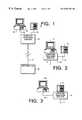
- FIG. 1provides a simplified view of a three port external adaptor, packet network attached telephone and computer, representing a first embodiment of the invention.
- FIG. 2provides a simplified view of a computer having an internal three port adaptor through which a telephone is attached to a data network, representing a second embodiment of the invention.
- FIG. 3provides a simplified view of a telephone having a three port adaptor, representing a third embodiment of the invention.
- FIG. 4is a simplified block diagram of the three port adaptor, including two packet network ports and a telephone port according to one embodiment of the present invention.
- FIG. 5is a simplified diagram of an alternative three port adaptor according to the present invention, in which the core logic comprises a layer 2 switch.
- FIG. 6illustrates an alternative embodiment of the three port adaptor of the present invention, which the core logic comprises multiplexing circuitry like a layer three router.
- FIG. 7provides an overview of an installation of a system according to the present invention including power transfer apparatus that supports both computer data and telephone data communications.
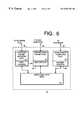
- FIG. 8is an overview of a power transfer apparatus for use with telephone equipment and network devices.
- FIG. 9is a schematic diagram of a power transfer apparatus for use with both computer data and telephone data implemented on a network interface card within a computer.
- the inventioninvolves combining voice communications with a packet network.
- Packet networksuse a digital packet structure (e.g., 802.x) to format packets.
- Each packetincludes a wrapper (e.g., header and trailer) and a payload.
- a telephoneis coupled to a fast Ethernet network device via an adaptor that is i) located internally within the telephone, ii) located internally within a computer or iii) located externally with regard to both the telephone and the computer.
- the inventioncan be broadly characterized as a voice communications device that is coupled to a packet network via a three-port adaptor.
- FIGS. 1-9illustrate three examples of the invention.
- a telephone 10is coupled to an adaptor 20 via a telephone cable 30 .
- a computer 40is connected to the adaptor 20 via cable 50 .
- the adaptor 20is connected to a packet network device such as a network hub 60 via a network medium 11 , such as an Ethernet segment.
- the network hub 60can be any packet network device, such as, for example, a router, a switch or a bridge.
- a second embodiment of the inventionis depicted.
- This second embodimentcan be termed a computer internal embodiment.
- the network medium 11 , the telephone 10 and the cable 30are the same as in the first embodiment, but the other components are different.
- a computer 17includes a processor, an input/output device like a keyboard, a display and a data backbone structure for interconnecting the components.
- the adaptor 18is located inside the computer 17 , and coupled to the data backbone structure of the computer, such as by an interface to a bus for peripheral devices (e.g. a PCI bus interface).
- the telephone 10is connected to the adaptor 18 via telephone cable 30 .
- the adaptor 18can take the form of a circuit board which is plugged into an expansion slot of the computer 17 .
- a circuit boardcould replace a conventional network adaptor.
- the downstream packet network connectorcomprises a bus interface or other connection to the backplane structure of the computer.
- the functions of a network adaptorwould be provided by the circuit board having, for example, an upstream RJ45 for the Ethernet cable, a downstream RJ11 for the telephone cable and a bus connector.
- the adaptoris included directly on the motherboard, or otherwise included in the computer system.
- the signals from the computer 30 , the packet network device 60 and the telephone 10 in FIG. 2can be processed in the same way in which the signals from the corresponding components in FIG. 1 are processed.
- FIG. 3illustrates a third embodiment of the invention.
- the third embodimentcan be termed a telephone internal embodiment.
- the local area network medium 11 , a computer 40 and the cable 50may be implemented as discussed above with regard to FIGS. 1 and 2.
- Other components of this embodimentare different in order to adapt to inclusion in the telephone.
- Telephone 12is coupled to the adaptor 14 located inside the telephone chassis.
- the computer 40is connected to the adaptor 14 via a cable 50 .
- the adaptor 14can take the form of a circuit board which is plugged into a receptacle of the telephone 12 .
- the circuit board, or other modulecan be inserted into a multi-conductor slot in the telephone.
- a network adaptoris provided having a network connection upstream and a repeated switched, routed or otherwise multiplexed network connection to a computer.
- the adaptorcan be embodied directly on the main circuit board of the telephone.
- the signals from the computer, the network hub and the telephone 12 in FIG. 3can be processed in the same way in which the signals from the corresponding components in FIG. 1 are processed.
- the structures for coupling the packet hub 60 to the adaptor ( 20 , 18 , 14 ) and the adaptor to the telephones and computerscan be any medium capable of performing the function of transferring signals, including, by way of example twisted pair wires, a coaxial cable, an optical fiber, an infrared link or a RF wireless link.
- a practical application of the invention that has value within the technological artsis combining voice and data in a local area network. Further, the invention has value in other network environments such as metropolitan area networking and wide area networking.
- FIGS. 4-6illustrate alternative implementations of the three port adaptor according to the present invention.
- the adaptorincludes an upstream packet network port 51 , a downstream packet network port 52 , and a downstream telephone port 53 .
- the upstream packet network port 51is coupled to a network medium 54 which also carries power.
- a power decoupler 55is coupled to the medium 54 and generates power as indicated by arrow 56 for supply to the components of the adaptor 50 , and to the telephone, as discussed in more detail below with reference to FIGS. 7-9.
- the downstream packet network port 52is coupled to a network medium 57 which is typically connected to a network interface card or medium access controller on a host computer.
- the downstream telephone port 53is connected across a medium 58 to a standard telephone.
- the packet network ports 51 and 52are directly connected to node core logic 60 , which in this example comprises a physical layer repeater for the network served by the network hub across medium 54 .
- the downstream telephone port 53is connected through a medium access control unit and digital signal processing MAC/DSP circuits 61 to the node core logic 60 .
- the node core logic 60distributes data packets which are received on any of the three ports to the other two ports according to standard repeater implementations.
- the upstream packet network port 51 and the downstream packet network port 52thus behave as ports on standard repeaters.
- the MAC/DSP circuits 61 coupled to the downstream telephone portoperate to translate telephone data in packet format received from the node core logic 60 into telephone data suitable for transmission through the telephone port 53 to the telephone.
- the MAC/DSP circuits 61serve to translate analog or digital telephone signals received across the medium 58 from the telephone into packets suitable for transmission on the network medium 54 to the network hub, and to the host computer through the upstream packet network port 51 and the downstream packet network port 52 .
- the repeater in the node core logic 60is based on any one of a number of commercially available repeater chips from manufacturers such as Advanced Micro Devices and National Semiconductor.
- the MAC/DSP circuits 61perform coding and decoding operations and analog-to-digital and digital-to-analog conversion, suitable for translation between the packet network and the telephone medium 58 as known in the art.
- the medium access controller MAC within the circuit 61conforms to the network medium 54 in the preferred system.
- the medium access controllermay comprise any one of a number of standard MACs specified by the IEEE referred to as the 802.x standards.
- the MACsupports 100 megabit Ethernet specified according to IEEE standard 802.3u, gigabit Ethernet, the FDDI standards, token ring standards or to any of a variety of other possible network media.
- the analog signals from telephone on port 58are digitized by the DSP circuits 61 and combined into packets suitable for transmission through the repeater in the node core logic 60 out onto the network. So the node core logic 60 can fan out packetized signals from the MAC/DSP circuit 61 to both the host computer on medium 57 and the network hub on medium 54 . It is sufficient in some embodiments that the packets carrying telephone data are transmitted only on medium 54 .
- FIG. 5illustrates another alternative implementation of the adaptor.
- the adaptoris given reference number 65 . It includes an upstream packet network port 66 which is coupled to a medium 67 , a downstream packet port 68 which is coupled to a medium 69 , and a downstream telephone port 70 which is coupled to a telephone medium 71 .
- the upstream packet portis coupled with a MAC 64 .
- the downstream packet port 68is coupled with a MAC 72 .
- the downstream telephone port 70is coupled to MAC/DSP circuits 73 like those described with respect to FIG. 4 .
- the node core logic 75is coupled to each of the ports 66 , 68 and 70 and serves to connect data from the medium 67 to the host computer on medium 69 or to the telephone on medium 70 as appropriate. Also the node core logic 75 serves to switch data from the telephone port 70 to the medium 67 to the network hub or to medium 69 to the host computer, and from the host computer to the medium 67 to the network hub or to the medium 71 for the telephone.
- the node core logic 75is implemented using switch control circuits which switch the packets on the three ports at the data link layer of the network.
- the MAC circuits 64 , 72 , 73serve to translate the network packets into data suitable for processing in the switch core 75 .
- the embodiment of FIG. 5is suitable for including within a computer as a network interface card.
- the switch functionality in the node core logic 75may also be implemented with repeater functionality as mentioned above with respect to FIG. 4 .
- FIG. 6illustrates yet another alternative embodiment of an adaptor 80 according to the present invention.
- the adaptor 80 in FIG. 6includes an upstream packet network port 81 , a downstream packet port 82 , and a downstream telephone port 83 .
- the MAC circuits 84 , 88 and 79which translate packets into data suitable for routing to the host computer on medium 86 or to the telephone through the DSP circuits 88 which are coupled to the downstream telephone port 83 .
- the node core logic 89comprises multiplexing circuits such as a router operating for example at the network layer for routing decisions which receive packets after processing by the MAC circuits 84 and direct the packets as appropriate through MAC 79 on the port 82 or to the MAC/DSP circuits 88 coupled with the downstream telephone port 83 .
- the MAC circuits 84 in this embodimentmay be configured to accept packets having more than one MAC address corresponding to the ports 82 and 83 . Alternatively, a single MAC address may be utilized, and the multiplexing decisions made based on higher layer processing within the protocol.
- a coupling devicecouples packetized telephone signals and packetized computer data and transmits the combined data to the adaptor.
- the adaptorreceives the data and helps separate the telephone data from the computer data.
- the adaptorthen transmits the telephone data to a telephone.
- the coupling deviceWhen the computer is powered down, such as during a power failure, the coupling device also couples a power signal to the combined data signal.
- the adaptoruses the power to power the telephone. Thus, a user can still use the telephone during a power failure.
- the telephone voice data(also called bearer data) is formatted as Ethernet packets in one example. These telephone Ethernet packets are communicated with the other Ethernet packets in an Ethernet network.
- a network infrastructure devicesuch as a hub, receives the Ethernet packets from the Ethernet network, and forwards packets addressed to a particular personal computer or to a telephone to its associated adaptor.
- FIG. 7shows the overall configuration of the one embodiment of the invention including a power transfer apparatus. The following lists the elements in FIG. 7 and then describes those elements.
- FIG. 7includes the following elements: an optional external power source 150 ; a power cable 120 ; a data cable 130 ; a power and data coupler 110 ; a network cable 160 ; an adaptor with a power and data decoupler 170 ; a network device 100 ; a telephone 190 ; an optional external power source 151 ; an optional external power source 191 ; and, a power cable 121 .
- the external power source 150couples to the power and data coupler 110 via the power cable 120 .
- the power cable 120couples to the power and data coupler 110 .
- the communications network 140transmits both packetized computer data signals 103 and packetized telephone data signals 102 .
- the communications network 140couples to the data cable 130 .
- the data cable 130couples to the power and data coupler 110 .
- the power and data coupler 110also couples to the network cable 160 .
- the network cable 160couples to the power and data decoupler 170 .
- the adaptor with the power and data decoupler 170couples to the network device 100 and the telephone 190 from external power source 150 .
- external power source 151rather than external power source 150 is relied on.
- external power source 151couples to the power cable 121 .
- the power cable 121couples to both the power and data decoupler 170 and to the network device 100 .
- the power and data decoupler 170supplies the telephone 190 from external power source 151 .
- the external power source 191supplies telephone 190 across line 192 .
- power from decoupler 110is only needed if external power supply 191 is off.
- the external power source 150provides a power signal 105 to the power and data coupler 110 .
- Various embodiments of the inventionuse different external power sources 150 : such as, a computer's power supply, a battery, or a wall outlet and adaptor. What is important, however, is that there is some source of power that can eventually be supplied to the network device 100 and telephone 190 .
- the power cable 120is a standard two wire power cable.
- Other embodimentsuse other power transfer apparatuses to provide power to the power and data coupler 110 .
- the external power source 150 and the power and data coupler 110are included in a hub.
- the communications network 140is representative of many different types of communications networks supported by various embodiments of the invention.
- Example communications networks 140include FDDI, Ethernet (including ten Mbits/s, one hundred Mbits/s, and one Gigabits/s standards), ATM, token ring, and AppleTalk.
- FDDIFrequency Division Duplex
- Ethernetincluding ten Mbits/s, one hundred Mbits/s, and one Gigabits/s standards
- ATMincluding ten Mbits/s, one hundred Mbits/s, and one Gigabits/s standards
- ATMtoken ring
- AppleTalkAppleTalk
- the packetized telephone data signal 102includes the bearer portion of a telephone signal.
- the bearer datais, for example, the packetized voice signal.
- the packetized telephone data signalincludes additional data supporting functions such as caller ID and voicemail access.
- the telephone data signal 102is formatted and transmitted in Ethernet packets. Of course, other Local Area Network protocols may be used. These Ethernet packets are formatted the same way as the Ethernet packets for the computer data 103 .
- the data signal 104comprises Ethernet packets.
- the power and data coupler 110will normally transmit the data signal 104 into 107 . However, when the power signal 192 is not available to power the telephone 190 and when the external power source 151 is not operating, the power and data coupler 110 couples the power signal 105 with the data signal 104 to produce a combined power and data signal 107 .
- the power and data coupler 110is described in greater detail below. What is important is that there is some combined power and data signal 107 that can eventually be supplied to the telephone 190 .
- the network cable 160includes one or more wires for transmitting the combined power and data signal 107 .
- the network cable 160includes an CAT-3 or CAT-5 twisted pair cable.
- the network device 100represents a class of devices supported by various embodiments of the invention.
- the network device 100includes a network computer.
- the network device 100includes a personal computer having a network interface card.
- the telephone 190is coupled to the adaptor with power and data decoupler 170 via the telephone cable 180 .
- the power and data decoupler 170may be part of the telephone 190 .
- the telephone 190is representative of any of a number of telephones. Various embodiments of the invention include plain old telephone service telephones, telephones with PBX features (such as are available from Nortel, Rolm, and Lucent Technology).
- the telephones 190communicate analog telephone signals over the telephone cable 180 .
- the telephone 190communicates digital telephone signals over the telephone cable 180 (in these embodiments, the telephone 190 includes the digital to analog circuits for converting the users voice signal to and from a digital representation).
- the telephone cable 180in one embodiment, is a four wire telephone cable. In other embodiments, the telephone cable 180 includes two wire, six wire, or more, telephone cable.
- a power signal 109is supplied to the network device 100 and to the power and data decoupler 170 via the power cable 121 .
- Various embodiments of the inventionuse different external power sources 151 : such as, a computer's power supply, a battery, or a wall outlet and adaptor. What is important, however, is that there is some source of power that is supplied to the network device 100 and to the telephone 190 during normal operation. However, when the external power source 151 is not available, such as during a power outage or when the power cable 121 is not connected to the power and data decoupler 170 , the power from the combined data and power signal 170 can be used to power the telephone 190 .
- external power source 191is not used, and the adaptor with power and data decoupler 170 is responsible for supplying telephone data and power to the telephone 190 , and computer data to the network device 100 and includes elements discussed above with respect to FIGS. 4-6.
- the adaptor 170combines power, from some source, and the telephone data signals to produce the telephone power and data signal 108 .
- the power and data decoupler 170combines the power signal 109 with a telephone data signal extracted the data and power signal 107 . (In this normal operation, the data and power signal 107 only includes data, not power.)
- the power and data decoupler 170decouples the power signal 105 from the data signal 104 .
- the power and data decoupler 170then couples the power signal with the telephone data signal to produce the telephone power and data signal 108 .
- a telephone data signal 102is combined with a computer data signal 103 in the communications network 140 .
- the data signal 104is communicated, via the data cable 130 , between the communications network 140 and the power and data coupler 110 .
- the power and data coupler 110simply transmits the data signal onto the network cable 160 (in this situation, the power and data signal 107 does not include a power signal).
- the adaptor 170receives network packets 107 , the telephone signals 108 and the computer data packets 106 .
- the computer data packets 106are communicated with the network device 100 .
- the power and data decoupler 170couples the power signal 109 with the telephone data packets and transmits the combined telephone power and data packet signal 108 to the telephone 190 .
- an external power source 191is coupled to telephone 190 .
- the power and data coupler 110couples the power signal 105 to the data signal 104 .
- the decoupler 170decouples the power signal from the power and data signal 107 .
- the adaptor 170still extracts the telephone data signal 108 and computer data signal 106 .
- the adaptor 170then couples the extracted telephone data and the decoupled power signal to create the telephone power and data signal 108 for use by the phone 190 . Note that even if the external power sources 191 or 151 are not working, the telephone 190 will continue to work.
- FIG. 8is an overview of a power transfer apparatus for use with network devices including computers. The following lists the elements in FIG. 8 and then describes those elements.
- FIG. 8includes the following elements: a PBX 242 ; a network server 240 ; a network 243 ; a hub 245 ; an external power source 150 ; a power outage coupler 200 ; a power outage coupler 202 ; a coupler 204 ; a network cable 260 ; an external power source 151 ; a power cable 220 ; a computer 280 with an internal adaptor; a telephone 290 ; a network cable 262 ; an external power source 152 ; a power cable 222 ; a network computer 282 with an internal adaptor; a telephone 292 ; a telephone cable 281 ; a network cable 264 ; a network computer 284 with an internal adaptor; a telephone 294 ; and, a telephone cable 283 .
- the PBX 242 , the network server 240 and the network 243work together to provide both telephone data and network data to devices coupled to the network 243 .
- the PBX 242 , the network server 240 and the network 243represent are example devices that provide the telephone functions, network server functions and network functions, respectively.
- the PBX 242includes a PBX having functions similar to a PBX from, for example, Nortel, Rolm, Lucent Technology, or Seimens. However, the PBX 242 has been modified to allow the network server 240 to send the PBX 242 's telephone signal data 102 as Ethernet packets.
- Various embodiments of the inventioninclude network servers 240 from, for example, Compaq, Hewlett-Packard, IBM, and Sun Microsystems.
- the network server 240acts as a server for the network and includes circuitry and software for communicating with the PBX 242 .
- the network serversupports Ethernet protocols for communicating data onto the network 243 .
- the network 243is illustrative of any of a number of computer networks including Ethernet, FDDI, AppleTalk, Token Ring, and ATM.
- the PBX 242is replaced with a PBX process running in the network server 240 and a gateway.
- a gatewayprovides the connection to the public switching network for the network 243 . Vienna Systems, Corporation, of Kanata, Ontario, Canada, provides such a gateway.
- the hub 245couples to the network 243 and allows network devices to communicate with the network 243 .
- Each devicecouples to a different port on the hub 245 .
- each couplercouples to a different port on the hub 245 .
- the hub 245is not needed to supply the data signal. Therefore, in these embodiments of the invention, the data signal is supplied by a network computer, a router, a switch, and/or a bridge.
- the external power source 150provides power to the couplers.
- Each couplerin this example, has a potentially different power requirements, therefore, different external power sources may be used.
- an adaptorcan be used to power the power outage coupler 200 .
- the adaptorsteps down the available electrical power from 117 or 220 volts AC to an AC or DC voltage that is high enough to provide adequate voltage for the telephone 290 .
- the power adaptorsupplies an output voltage of approximately negative forty-eight volts.
- Similar, example power adaptorsare described in U.S. patent application Ser. No. 08/865,016, filed on May 29, 1997, entitled, “Power Transfer Apparatus for Concurrently Transmitting Data and Power Over Data Wires,” having inventors David A. Fisher, Lawrence M. Burns, and Stephen Muther.
- the couplersprovide similar coupling functions as those found in power and data coupler 110 (FIG. 7 ).
- Each couplercouples power and data signals for use by a telephone and some other computing device.
- the amount of power coupled, and when the power is coupled,is what varies between the various couplers. This will be described in greater detail below.
- these couplers, and the present configuration,is merely illustrative. In some embodiments of the invention, each coupler has the same functionality.
- the hub 245includes the couplers and the external power source 150 .
- coupler 200The following describes three example power and data coupling systems corresponding to coupler 200 , coupler 202 , and coupler 204 respectively. Each of these systems will now be described.
- the coupler 200is coupled to the computer 280 via the network cable 260 .
- the external power source 151couples to the computer 280 via the power cable 220 .
- the telephone 290couples to the computer 280 .
- the computer 280is the network device 100 , and the computer 280 includes the power and data decoupler 170 .
- the power and outage coupler 200is notified to couple power with the data signal from the hub 245 .
- the power and data decoupler 170in the computer 280 , can then switch the source of power from the external power source 151 to the power from the network cable 260 . This system is described in greater detail below with respect to FIG. 9 .
- the coupler 202is coupled to the network computer 282 .
- the external power source 152couples to the network computer 282 via the power cable 222 .
- the telephone 292couples to the network computer 282 via the telephone cable 283 .
- the network computer 282includes a power and data decoupler similar to the one in the system of FIG. 7 .
- the power outage coupler 202and corresponding power and data decoupler, operates in a similar manner as the power outage coupler 200 system, except that the power outage coupler 202 supplies sufficient power to the decoupler to power both the telephone and the network computer 282 .
- separate power signalse.g., twenty-four volts DC and minus forty-eight volts DC
- the decouplerdecouples both these power signals from any data signals.
- the different power signalsare for the different power needs of the telephone 292 and the network computer 282 .
- only one power signalis transmitted, which is then modified by the decoupler for use by the network computer 282 and the telephone 292 .
- the coupler 204is coupled to the network computer 284 via the network cable 264 .
- the coupler 204is similar to the power outage coupler 202 , but the coupler 204 constantly supplies the power for the network computer 284 and the telephone 294 .
- the telephonehas its own external power supply, such as a battery or a wall adaptor.
- the couplercouples a power signal to the network cable 160 when the telephone's power supply fails.
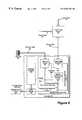
- FIG. 9is a schematic diagram of a power transfer apparatus that supports telephone features. This apparatus corresponds to the system associated with the coupler 200 in FIG. 8 . The following first lists the elements in FIG. 9, then describes the elements' couplings, and then describes the elements' interactions.
- FIG. 9includes the power cable 322 , the data cable 130 , a power outage coupler 200 , the network cable 260 , the computer 280 , the telephone 290 , the telephone cable 281 , the external power source 151 , and the computer power cable 220 .
- the computer 280includes a network interface card (NIC) 300 , a processor subsystem 330 , and a power subsystem 340 .
- the NIC 300includes a power outage decoupler 370 , an adaptor 320 providing network interface and telephony circuits, a power source switch 390 , and a telephone coupler 345 .
- the elements of FIG. 9are coupled as follows.
- the power cable 322 , the data cable 130 , and the network cable 260are coupled to the power outage coupler 200 in the same way as shown in FIG. 7 .
- the network cable 260also couples to the input port of the power outage decoupler 370 on the NIC 300 .
- the data output port of the decoupler 370couples to the network interface and telephony circuit 320 .
- the computer data port of the adaptor 320couples to the processor subsystem 330 .
- the power output port of the decoupler 370couples to one of the two inputs of the power source switch 390 .
- the other input of the power source switch 390is coupled to the power subsystem 340 .
- the power subsystem 340also couples to the processor subsystem 330 and to the external power source 151 (via the computer power cable 220 ).
- the output of the power source switch 390couples to the power input ports of the network interface and telephony circuit 320 and the telephone coupler 345 .
- the telephone data port of the network interface and telephony circuit 320is coupled to the data input port of the telephony coupler 345 .
- the output of the telephone coupler 345is coupled to the telephone cable 281 .
- the telephone cable 281couples to the telephone 290 .
- the power subsystem 340is illustrative of a PC power supply.
- the power subsystem 340generally provides the power for the computer 280 , including the processor subsystem and the NIC 300 .
- the processor subsystem 330represents those elements of the computer 280 that are not directly involved with the network interface functions of the computer 280 .
- the NIC 300includes the elements to perform three main functions. Each of these functions will now be described.
- the NIC 300supports network interface services, such as Ethernet communications, for the computer 280 .
- these servicesare supported using an Ethernet communications circuit in the network interface and telephony circuit 320 .
- 3Com Corporationof Santa Clara, Calif., supplies such Ethernet communication circuits.
- the NIC 300also provides telephony services for the telephone 290 .
- the network interface and telephony circuits in adaptor 320receive data from the power outage decoupler 370
- the network interface and telephony circuits in adaptor 320extract telephony related data and reformats it for use by the telephone. In one embodiment, this includes providing digital telephone data to the telephone coupler 345 .
- the telephone coupler 345then converts the digital telephone data to an analog signal and combines this analog signal with the power from the power source switch 390 .
- the telephone coupler 345includes circuits similar to those found in a PBX, or in a telephone for use with a PBX.
- the telephone 345includes circuits similar to those found in a line card at a central switching office for coupling power and data together.
- the NIC 300switches between the available power supplies.
- the power source switch 390will attempt to use the power from the subsystem 340 . However, if a power outage prevents the power subsystem 340 from supplying sufficient power to power the telephone, the power supply switch 390 will switch to using the network power signal 305 .
- the network interface cardwill signal the power outage coupler 200 to begin supplying power because of the insufficient computer power signal 303 .
- the examples described aboveare merely illustrative. Other embodiments of the invention include different configurations and elements.
- some of the circuits in the power source switch 390are shared by the power outage decoupler 370 and the telephone coupler 345 .
- the power outage coupler 200 , the power outage decoupler 370 , and/or the telephone coupler 345include electrical isolation circuitry. Examples of such circuitry are described in U.S. patent application Ser. No. 08/865,016, filed on May 29, 1997, entitled, “Power Transfer Apparatus for Concurrently Transmitting Data and Power Over Data Wires,” having inventors David A. Fisher, Lawrence M. Burns, and Stephen Muther.
- the power coupled by the coupler 200is an AC power signal
- the power coupled by the coupler 200is a DC power signal.
- power, computer data and telephone dataare combined and transmitted to a computer.
- the computeruses the power to power a telephone coupled with the computer. Because the power and data are combined, the telephone can be powered even when the computer has been powered off.
Landscapes
- Engineering & Computer Science (AREA)
- Signal Processing (AREA)
- Computer Networks & Wireless Communication (AREA)
- Data Exchanges In Wide-Area Networks (AREA)
Abstract
Description
Claims (24)
Priority Applications (1)
| Application Number | Priority Date | Filing Date | Title |
|---|---|---|---|
| US09/086,103US6587454B1 (en) | 1997-05-29 | 1998-05-28 | Network adaptor for telephone and data traffic |
Applications Claiming Priority (2)
| Application Number | Priority Date | Filing Date | Title |
|---|---|---|---|
| US08/865,015US6449348B1 (en) | 1997-05-29 | 1997-05-29 | Power transfer apparatus for use by network devices including telephone equipment |
| US09/086,103US6587454B1 (en) | 1997-05-29 | 1998-05-28 | Network adaptor for telephone and data traffic |
Related Parent Applications (1)
| Application Number | Title | Priority Date | Filing Date |
|---|---|---|---|
| US08/865,015Continuation-In-PartUS6449348B1 (en) | 1997-05-29 | 1997-05-29 | Power transfer apparatus for use by network devices including telephone equipment |
Publications (1)
| Publication Number | Publication Date |
|---|---|
| US6587454B1true US6587454B1 (en) | 2003-07-01 |
Family
ID=46279397
Family Applications (1)
| Application Number | Title | Priority Date | Filing Date |
|---|---|---|---|
| US09/086,103Expired - LifetimeUS6587454B1 (en) | 1997-05-29 | 1998-05-28 | Network adaptor for telephone and data traffic |
Country Status (1)
| Country | Link |
|---|---|
| US (1) | US6587454B1 (en) |
Cited By (41)
| Publication number | Priority date | Publication date | Assignee | Title |
|---|---|---|---|---|
| US20020021690A1 (en)* | 1999-09-13 | 2002-02-21 | Frank Preiss | Integrated access device controller |
| US20030177260A1 (en)* | 2000-09-28 | 2003-09-18 | Rainer Windecker | Method and device for transmitting information comprising a speech part and a data part |
| US20040268160A1 (en)* | 2003-06-30 | 2004-12-30 | Atkinson Douglas A. | Power adapter and broadband line extender system and method |
| US20050013320A1 (en)* | 1998-07-28 | 2005-01-20 | Serconet Ltd. | Local area network of serial intelligent cells |
| US6868072B1 (en)* | 1999-03-19 | 2005-03-15 | Broadcom Corporation | Home phone line network architecture |
| US20050105477A1 (en)* | 1999-07-20 | 2005-05-19 | Serconet, Ltd. | Network for telephony and data communication |
| US20050111491A1 (en)* | 2003-10-23 | 2005-05-26 | Panduit Corporation | System to guide and monitor the installation and revision of network cabling of an active jack network |
| US20050110618A1 (en)* | 2003-10-10 | 2005-05-26 | Alcatel | Ethernet card for connection to a local network, for controlling connection to a communication terminal |
| US20050159036A1 (en)* | 2003-11-24 | 2005-07-21 | Caveney Jack E. | Communications patch panel systems and methods |
| US20050249147A1 (en)* | 2004-05-04 | 2005-11-10 | Theglobe.Com | Wireless network telecommunications system |
| US7123701B2 (en) | 2000-03-20 | 2006-10-17 | Serconet, Ltd. | Telephone outlet for implementing a local area network over telephone lines and a local area network using such outlets |
| US20060262727A1 (en)* | 2005-05-19 | 2006-11-23 | Panduit Corp. | Method and apparatus for documenting network paths |
| US20070070911A1 (en)* | 2005-09-29 | 2007-03-29 | Goldberg Keith J | Method for testing links in a wireless network |
| US7274688B2 (en) | 2000-04-18 | 2007-09-25 | Serconet Ltd. | Telephone communication system over a single telephone line |
| US20080030971A1 (en)* | 2006-08-01 | 2008-02-07 | Tyco Electronics Corporation | Wall-Mounted Network Outlet |
| US7376734B2 (en) | 2002-02-14 | 2008-05-20 | Panduit Corp. | VOIP telephone location system |
| US7400617B1 (en)* | 1999-09-13 | 2008-07-15 | Infineon Technologies North America Corp. | Integrated voice-over-internet protocol processor |
| US20080214140A1 (en)* | 2005-09-28 | 2008-09-04 | Panduit Corp. | Powered patch panel |
| US7436842B2 (en) | 2001-10-11 | 2008-10-14 | Serconet Ltd. | Outlet with analog signal adapter, a method for use thereof and a network using said outlet |
| US7447144B2 (en) | 2000-09-21 | 2008-11-04 | Serconet, Ltd. | Telephone communication system and method over local area network wiring |
| US7455527B2 (en) | 2004-05-03 | 2008-11-25 | Panduit Corp. | Powered patch panel |
| US7519000B2 (en) | 2002-01-30 | 2009-04-14 | Panduit Corp. | Systems and methods for managing a network |
| US7522615B2 (en) | 2002-11-13 | 2009-04-21 | Serconet, Ltd. | Addressable outlet, and a network using same |
| US7542554B2 (en) | 2001-07-05 | 2009-06-02 | Serconet, Ltd | Telephone outlet with packet telephony adapter, and a network using same |
| US7626979B1 (en)* | 2004-07-28 | 2009-12-01 | Sprint Communications Company L.P. | Packet voice network border control |
| US7633966B2 (en) | 2000-04-19 | 2009-12-15 | Mosaid Technologies Incorporated | Network combining wired and non-wired segments |
| US7656904B2 (en) | 2003-03-13 | 2010-02-02 | Mosaid Technologies Incorporated | Telephone system having multiple distinct sources and accessories therefor |
| US7686653B2 (en) | 2003-09-07 | 2010-03-30 | Mosaid Technologies Incorporated | Modular outlet |
| US7702095B2 (en) | 2003-01-30 | 2010-04-20 | Mosaid Technologies Incorporated | Method and system for providing DC power on local telephone lines |
| US20100100750A1 (en)* | 2008-10-16 | 2010-04-22 | Cisco Technology, Inc. | Techniques for ensuring power delivery over only data-active pairs of data communications cabling |
| US20100237846A1 (en)* | 2009-03-17 | 2010-09-23 | Cisco Technology, Inc. | Controlling inline power at at powered device |
| US7835386B2 (en) | 1999-07-07 | 2010-11-16 | Mosaid Technologies Incorporated | Local area network for distributing data communication, sensing and control signals |
| US7873058B2 (en) | 2004-11-08 | 2011-01-18 | Mosaid Technologies Incorporated | Outlet with analog signal adapter, a method for use thereof and a network using said outlet |
| US7881281B1 (en) | 2004-07-02 | 2011-02-01 | Sprint Communications Company L.P. | Border control system, method, and software |
| US7978689B1 (en)* | 2002-06-24 | 2011-07-12 | At&T Intellectual Property I, L.P. | Apparatus, system and method for transmitting voice and data over ethernet |
| US8155012B2 (en) | 1998-04-10 | 2012-04-10 | Chrimar Systems, Inc. | System and method for adapting a piece of terminal equipment |
| US8325770B2 (en) | 2003-08-06 | 2012-12-04 | Panduit Corp. | Network managed device installation and provisioning technique |
| US8565417B2 (en)* | 2004-02-16 | 2013-10-22 | Mosaid Technologies Incorporated | Outlet add-on module |
| US8800059B2 (en) | 1999-03-19 | 2014-08-05 | Broadcom Corporation | System and method for processing and protecting content |
| US8858263B2 (en) | 2011-08-08 | 2014-10-14 | Novano Corporation | Service over ethernet InterConnectable wall plate (SoEICWP) module |
| US10986165B2 (en) | 2004-01-13 | 2021-04-20 | May Patents Ltd. | Information device |
Citations (12)
| Publication number | Priority date | Publication date | Assignee | Title |
|---|---|---|---|---|
| US4740955A (en)* | 1986-10-29 | 1988-04-26 | Tie/Communications, Inc. | Communications system having voice and digital data capability and employing a plurality of voice and data buses in main service unit and serial packetized transmission to and from telephones |
| US5067125A (en)* | 1988-08-25 | 1991-11-19 | Canon Kabushiki Kaisha | Telephone system for isdn and public telephone networks |
| US5633920A (en) | 1994-02-10 | 1997-05-27 | Elonex I.P. Holdings, Ltd. | Smart phone |
| US5889856A (en)* | 1997-05-22 | 1999-03-30 | Centillium Technology Corp. | ADSL integrated line card with digital splitter and POTS CODEC without bulky analog splitter |
| US5894508A (en)* | 1995-11-03 | 1999-04-13 | Lg Semicon Co., Ltd. | Automatic power control apparatus of a PC mounted fax/modem |
| US5930340A (en)* | 1997-07-07 | 1999-07-27 | Advanced Micro Devices | Device and method for isolating voice and data signals on a common carrier |
| US5970066A (en)* | 1996-12-12 | 1999-10-19 | Paradyne Corporation | Virtual ethernet interface |
| US5991292A (en)* | 1997-03-06 | 1999-11-23 | Nortel Networks Corporation | Network access in multi-service environment |
| US6049826A (en)* | 1998-02-04 | 2000-04-11 | 3Com Corporation | Method and system for cable modem initialization using dynamic servers |
| US6049531A (en)* | 1997-07-14 | 2000-04-11 | At&T Corp | Real-time multimedia conferencing over an ATM network using an intelligent ATM ADSL modem and ADSL access |
| US6128293A (en)* | 1995-12-20 | 2000-10-03 | Nortel Networks Corporation | Multiservice access management system |
| US6131012A (en)* | 1998-05-26 | 2000-10-10 | Nera Wireless Broadband Access As | Method and system for a micro-channel bank for providing voice, data, and multimedia services in a wireless local loop system |
- 1998
- 1998-05-28USUS09/086,103patent/US6587454B1/ennot_activeExpired - Lifetime
Patent Citations (12)
| Publication number | Priority date | Publication date | Assignee | Title |
|---|---|---|---|---|
| US4740955A (en)* | 1986-10-29 | 1988-04-26 | Tie/Communications, Inc. | Communications system having voice and digital data capability and employing a plurality of voice and data buses in main service unit and serial packetized transmission to and from telephones |
| US5067125A (en)* | 1988-08-25 | 1991-11-19 | Canon Kabushiki Kaisha | Telephone system for isdn and public telephone networks |
| US5633920A (en) | 1994-02-10 | 1997-05-27 | Elonex I.P. Holdings, Ltd. | Smart phone |
| US5894508A (en)* | 1995-11-03 | 1999-04-13 | Lg Semicon Co., Ltd. | Automatic power control apparatus of a PC mounted fax/modem |
| US6128293A (en)* | 1995-12-20 | 2000-10-03 | Nortel Networks Corporation | Multiservice access management system |
| US5970066A (en)* | 1996-12-12 | 1999-10-19 | Paradyne Corporation | Virtual ethernet interface |
| US5991292A (en)* | 1997-03-06 | 1999-11-23 | Nortel Networks Corporation | Network access in multi-service environment |
| US5889856A (en)* | 1997-05-22 | 1999-03-30 | Centillium Technology Corp. | ADSL integrated line card with digital splitter and POTS CODEC without bulky analog splitter |
| US5930340A (en)* | 1997-07-07 | 1999-07-27 | Advanced Micro Devices | Device and method for isolating voice and data signals on a common carrier |
| US6049531A (en)* | 1997-07-14 | 2000-04-11 | At&T Corp | Real-time multimedia conferencing over an ATM network using an intelligent ATM ADSL modem and ADSL access |
| US6049826A (en)* | 1998-02-04 | 2000-04-11 | 3Com Corporation | Method and system for cable modem initialization using dynamic servers |
| US6131012A (en)* | 1998-05-26 | 2000-10-10 | Nera Wireless Broadband Access As | Method and system for a micro-channel bank for providing voice, data, and multimedia services in a wireless local loop system |
Cited By (133)
| Publication number | Priority date | Publication date | Assignee | Title |
|---|---|---|---|---|
| US9019838B2 (en) | 1998-04-10 | 2015-04-28 | Chrimar Systems, Inc. | Central piece of network equipment |
| US9812825B2 (en) | 1998-04-10 | 2017-11-07 | Chrimar Systems, Inc. | Ethernet device |
| US9049019B2 (en) | 1998-04-10 | 2015-06-02 | Chrimar Systems, Inc. | Network equipment and optional tether |
| US8155012B2 (en) | 1998-04-10 | 2012-04-10 | Chrimar Systems, Inc. | System and method for adapting a piece of terminal equipment |
| US8902760B2 (en) | 1998-04-10 | 2014-12-02 | Chrimar Systems, Inc. | Network system and optional tethers |
| US8942107B2 (en) | 1998-04-10 | 2015-01-27 | Chrimar Systems, Inc. | Piece of ethernet terminal equipment |
| US7035280B2 (en) | 1998-07-28 | 2006-04-25 | Serconet Ltd. | Local area network of serial intelligent cells |
| US7653015B2 (en) | 1998-07-28 | 2010-01-26 | Mosaid Technologies Incorporated | Local area network of serial intelligent cells |
| US7852874B2 (en) | 1998-07-28 | 2010-12-14 | Mosaid Technologies Incorporated | Local area network of serial intelligent cells |
| US7965735B2 (en) | 1998-07-28 | 2011-06-21 | Mosaid Technologies Incorporated | Local area network of serial intelligent cells |
| US7978726B2 (en) | 1998-07-28 | 2011-07-12 | Mosaid Technologies Incorporated | Local area network of serial intelligent cells |
| US8908673B2 (en) | 1998-07-28 | 2014-12-09 | Conversant Intellectual Property Management Incorporated | Local area network of serial intelligent cells |
| US7006523B2 (en) | 1998-07-28 | 2006-02-28 | Serconet Ltd. | Local area network of serial intelligent cells |
| US7016368B2 (en) | 1998-07-28 | 2006-03-21 | Serconet, Ltd. | Local area network of serial intelligent cells |
| US8325636B2 (en) | 1998-07-28 | 2012-12-04 | Mosaid Technologies Incorporated | Local area network of serial intelligent cells |
| US7986708B2 (en) | 1998-07-28 | 2011-07-26 | Mosaid Technologies Incorporated | Local area network of serial intelligent cells |
| US7095756B2 (en) | 1998-07-28 | 2006-08-22 | Serconet, Ltd. | Local area network of serial intelligent cells |
| US7830858B2 (en) | 1998-07-28 | 2010-11-09 | Mosaid Technologies Incorporated | Local area network of serial intelligent cells |
| US8270430B2 (en) | 1998-07-28 | 2012-09-18 | Mosaid Technologies Incorporated | Local area network of serial intelligent cells |
| US7187695B2 (en) | 1998-07-28 | 2007-03-06 | Serconet Ltd. | Local area network of serial intelligent cells |
| US8885659B2 (en) | 1998-07-28 | 2014-11-11 | Conversant Intellectual Property Management Incorporated | Local area network of serial intelligent cells |
| US8885660B2 (en) | 1998-07-28 | 2014-11-11 | Conversant Intellectual Property Management Incorporated | Local area network of serial intelligent cells |
| US8867523B2 (en) | 1998-07-28 | 2014-10-21 | Conversant Intellectual Property Management Incorporated | Local area network of serial intelligent cells |
| US7221679B2 (en) | 1998-07-28 | 2007-05-22 | Serconet Ltd. | Local area network of serial intelligent cells |
| US7424031B2 (en) | 1998-07-28 | 2008-09-09 | Serconet, Ltd. | Local area network of serial intelligent cells |
| US20050013320A1 (en)* | 1998-07-28 | 2005-01-20 | Serconet Ltd. | Local area network of serial intelligent cells |
| US7292600B2 (en) | 1998-07-28 | 2007-11-06 | Serconet Ltd. | Local area network of serial intellegent cells |
| US8800059B2 (en) | 1999-03-19 | 2014-08-05 | Broadcom Corporation | System and method for processing and protecting content |
| US6868072B1 (en)* | 1999-03-19 | 2005-03-15 | Broadcom Corporation | Home phone line network architecture |
| US8121132B2 (en) | 1999-07-07 | 2012-02-21 | Mosaid Technologies Incorporated | Local area network for distributing data communication, sensing and control signals |
| US8582598B2 (en) | 1999-07-07 | 2013-11-12 | Mosaid Technologies Incorporated | Local area network for distributing data communication, sensing and control signals |
| US7835386B2 (en) | 1999-07-07 | 2010-11-16 | Mosaid Technologies Incorporated | Local area network for distributing data communication, sensing and control signals |
| US20050226226A1 (en)* | 1999-07-20 | 2005-10-13 | Serconet, Ltd. | Network for telephony and data communication |
| US7483524B2 (en) | 1999-07-20 | 2009-01-27 | Serconet, Ltd | Network for telephony and data communication |
| US7522713B2 (en) | 1999-07-20 | 2009-04-21 | Serconet, Ltd. | Network for telephony and data communication |
| US7492875B2 (en) | 1999-07-20 | 2009-02-17 | Serconet, Ltd. | Network for telephony and data communication |
| US20050105477A1 (en)* | 1999-07-20 | 2005-05-19 | Serconet, Ltd. | Network for telephony and data communication |
| US20050111636A1 (en)* | 1999-07-20 | 2005-05-26 | Serconet, Ltd | Network for telephony and data communication |
| US8351582B2 (en) | 1999-07-20 | 2013-01-08 | Mosaid Technologies Incorporated | Network for telephony and data communication |
| US8929523B2 (en) | 1999-07-20 | 2015-01-06 | Conversant Intellectual Property Management Inc. | Network for telephony and data communication |
| US7061904B2 (en)* | 1999-09-13 | 2006-06-13 | Infineon Technologies North America Corp. | Integrated access device controller |
| US7400617B1 (en)* | 1999-09-13 | 2008-07-15 | Infineon Technologies North America Corp. | Integrated voice-over-internet protocol processor |
| US20020021690A1 (en)* | 1999-09-13 | 2002-02-21 | Frank Preiss | Integrated access device controller |
| US8363797B2 (en) | 2000-03-20 | 2013-01-29 | Mosaid Technologies Incorporated | Telephone outlet for implementing a local area network over telephone lines and a local area network using such outlets |
| US7123701B2 (en) | 2000-03-20 | 2006-10-17 | Serconet, Ltd. | Telephone outlet for implementing a local area network over telephone lines and a local area network using such outlets |
| US8855277B2 (en) | 2000-03-20 | 2014-10-07 | Conversant Intellectual Property Managment Incorporated | Telephone outlet for implementing a local area network over telephone lines and a local area network using such outlets |
| US7715534B2 (en) | 2000-03-20 | 2010-05-11 | Mosaid Technologies Incorporated | Telephone outlet for implementing a local area network over telephone lines and a local area network using such outlets |
| US7522714B2 (en) | 2000-03-20 | 2009-04-21 | Serconet Ltd. | Telephone outlet for implementing a local area network over telephone lines and a local area network using such outlets |
| US7397791B2 (en) | 2000-04-18 | 2008-07-08 | Serconet, Ltd. | Telephone communication system over a single telephone line |
| US7466722B2 (en) | 2000-04-18 | 2008-12-16 | Serconet Ltd | Telephone communication system over a single telephone line |
| US7593394B2 (en) | 2000-04-18 | 2009-09-22 | Mosaid Technologies Incorporated | Telephone communication system over a single telephone line |
| US8000349B2 (en) | 2000-04-18 | 2011-08-16 | Mosaid Technologies Incorporated | Telephone communication system over a single telephone line |
| US8223800B2 (en) | 2000-04-18 | 2012-07-17 | Mosaid Technologies Incorporated | Telephone communication system over a single telephone line |
| US7274688B2 (en) | 2000-04-18 | 2007-09-25 | Serconet Ltd. | Telephone communication system over a single telephone line |
| US8559422B2 (en) | 2000-04-18 | 2013-10-15 | Mosaid Technologies Incorporated | Telephone communication system over a single telephone line |
| US7633966B2 (en) | 2000-04-19 | 2009-12-15 | Mosaid Technologies Incorporated | Network combining wired and non-wired segments |
| US8873586B2 (en) | 2000-04-19 | 2014-10-28 | Conversant Intellectual Property Management Incorporated | Network combining wired and non-wired segments |
| US8873575B2 (en) | 2000-04-19 | 2014-10-28 | Conversant Intellectual Property Management Incorporated | Network combining wired and non-wired segments |
| US8982904B2 (en) | 2000-04-19 | 2015-03-17 | Conversant Intellectual Property Management Inc. | Network combining wired and non-wired segments |
| US8867506B2 (en) | 2000-04-19 | 2014-10-21 | Conversant Intellectual Property Management Incorporated | Network combining wired and non-wired segments |
| US8982903B2 (en) | 2000-04-19 | 2015-03-17 | Conversant Intellectual Property Management Inc. | Network combining wired and non-wired segments |
| US8848725B2 (en) | 2000-04-19 | 2014-09-30 | Conversant Intellectual Property Management Incorporated | Network combining wired and non-wired segments |
| US7489709B2 (en) | 2000-09-21 | 2009-02-10 | Serconet Ltd. | Telephone communication system and method over local area network wiring |
| US7480233B2 (en) | 2000-09-21 | 2009-01-20 | Serconet Ltd. | Telephone communication system and method over local area network wiring |
| US8817779B2 (en) | 2000-09-21 | 2014-08-26 | Conversant Intellectual Property Management Incorporated | Telephone communication system and method over local area network wiring |
| US7447144B2 (en) | 2000-09-21 | 2008-11-04 | Serconet, Ltd. | Telephone communication system and method over local area network wiring |
| US8619538B2 (en) | 2000-09-21 | 2013-12-31 | Mosaid Technologies Incorporated | Communication system and method over local area network wiring |
| US7843799B2 (en) | 2000-09-21 | 2010-11-30 | Mosaid Technologies Incorporated | Telephone communication system and method over local area network wiring |
| US7352738B2 (en)* | 2000-09-28 | 2008-04-01 | Siemens Aktiengesellschaft | Method and device for transmitting information formed of a speech part and a data part |
| US20030177260A1 (en)* | 2000-09-28 | 2003-09-18 | Rainer Windecker | Method and device for transmitting information comprising a speech part and a data part |
| US8761186B2 (en) | 2001-07-05 | 2014-06-24 | Conversant Intellectual Property Management Incorporated | Telephone outlet with packet telephony adapter, and a network using same |
| US7680255B2 (en) | 2001-07-05 | 2010-03-16 | Mosaid Technologies Incorporated | Telephone outlet with packet telephony adaptor, and a network using same |
| US8472593B2 (en) | 2001-07-05 | 2013-06-25 | Mosaid Technologies Incorporated | Telephone outlet with packet telephony adaptor, and a network using same |
| US7769030B2 (en) | 2001-07-05 | 2010-08-03 | Mosaid Technologies Incorporated | Telephone outlet with packet telephony adapter, and a network using same |
| US7542554B2 (en) | 2001-07-05 | 2009-06-02 | Serconet, Ltd | Telephone outlet with packet telephony adapter, and a network using same |
| US7436842B2 (en) | 2001-10-11 | 2008-10-14 | Serconet Ltd. | Outlet with analog signal adapter, a method for use thereof and a network using said outlet |
| US7860084B2 (en) | 2001-10-11 | 2010-12-28 | Mosaid Technologies Incorporated | Outlet with analog signal adapter, a method for use thereof and a network using said outlet |
| US7889720B2 (en) | 2001-10-11 | 2011-02-15 | Mosaid Technologies Incorporated | Outlet with analog signal adapter, a method for use thereof and a network using said outlet |
| US7953071B2 (en) | 2001-10-11 | 2011-05-31 | Mosaid Technologies Incorporated | Outlet with analog signal adapter, a method for use thereof and a network using said outlet |
| US7453895B2 (en) | 2001-10-11 | 2008-11-18 | Serconet Ltd | Outlet with analog signal adapter, a method for use thereof and a network using said outlet |
| US7519000B2 (en) | 2002-01-30 | 2009-04-14 | Panduit Corp. | Systems and methods for managing a network |
| US7376734B2 (en) | 2002-02-14 | 2008-05-20 | Panduit Corp. | VOIP telephone location system |
| US7978689B1 (en)* | 2002-06-24 | 2011-07-12 | At&T Intellectual Property I, L.P. | Apparatus, system and method for transmitting voice and data over ethernet |
| US8295185B2 (en) | 2002-11-13 | 2012-10-23 | Mosaid Technologies Inc. | Addressable outlet for use in wired local area network |
| US7990908B2 (en) | 2002-11-13 | 2011-08-02 | Mosaid Technologies Incorporated | Addressable outlet, and a network using the same |
| US7911992B2 (en) | 2002-11-13 | 2011-03-22 | Mosaid Technologies Incorporated | Addressable outlet, and a network using the same |
| US7522615B2 (en) | 2002-11-13 | 2009-04-21 | Serconet, Ltd. | Addressable outlet, and a network using same |
| US8107618B2 (en) | 2003-01-30 | 2012-01-31 | Mosaid Technologies Incorporated | Method and system for providing DC power on local telephone lines |
| US7702095B2 (en) | 2003-01-30 | 2010-04-20 | Mosaid Technologies Incorporated | Method and system for providing DC power on local telephone lines |
| US8787562B2 (en) | 2003-01-30 | 2014-07-22 | Conversant Intellectual Property Management Inc. | Method and system for providing DC power on local telephone lines |
| US8238328B2 (en) | 2003-03-13 | 2012-08-07 | Mosaid Technologies Incorporated | Telephone system having multiple distinct sources and accessories therefor |
| US7738453B2 (en) | 2003-03-13 | 2010-06-15 | Mosaid Technologies Incorporated | Telephone system having multiple sources and accessories therefor |
| US7746905B2 (en) | 2003-03-13 | 2010-06-29 | Mosaid Technologies Incorporated | Private telephone network connected to more than one public network |
| US7656904B2 (en) | 2003-03-13 | 2010-02-02 | Mosaid Technologies Incorporated | Telephone system having multiple distinct sources and accessories therefor |
| US20040268160A1 (en)* | 2003-06-30 | 2004-12-30 | Atkinson Douglas A. | Power adapter and broadband line extender system and method |
| US7194639B2 (en)* | 2003-06-30 | 2007-03-20 | Tellabs Vienna, Inc. | Power adapter and broadband line extender system and method |
| US8325770B2 (en) | 2003-08-06 | 2012-12-04 | Panduit Corp. | Network managed device installation and provisioning technique |
| US7686653B2 (en) | 2003-09-07 | 2010-03-30 | Mosaid Technologies Incorporated | Modular outlet |
| US20050110618A1 (en)* | 2003-10-10 | 2005-05-26 | Alcatel | Ethernet card for connection to a local network, for controlling connection to a communication terminal |
| US7231535B2 (en)* | 2003-10-10 | 2007-06-12 | Alcatel | Ethernet card for connection to a local network, for controlling connection to a communication terminal |
| US20080049790A1 (en)* | 2003-10-23 | 2008-02-28 | Panduit Corp. | System to Guide and Monitor the Installation and Revision of Network Cabling of an Active Jack Network System |
| US20050111491A1 (en)* | 2003-10-23 | 2005-05-26 | Panduit Corporation | System to guide and monitor the installation and revision of network cabling of an active jack network |
| US20050159036A1 (en)* | 2003-11-24 | 2005-07-21 | Caveney Jack E. | Communications patch panel systems and methods |
| US7207846B2 (en) | 2003-11-24 | 2007-04-24 | Panduit Corp. | Patch panel with a motherboard for connecting communication jacks |
| US10986164B2 (en) | 2004-01-13 | 2021-04-20 | May Patents Ltd. | Information device |
| US10986165B2 (en) | 2004-01-13 | 2021-04-20 | May Patents Ltd. | Information device |
| US11032353B2 (en) | 2004-01-13 | 2021-06-08 | May Patents Ltd. | Information device |
| US11095708B2 (en) | 2004-01-13 | 2021-08-17 | May Patents Ltd. | Information device |
| US8611528B2 (en) | 2004-02-16 | 2013-12-17 | Mosaid Technologies Incorporated | Outlet add-on module |
| US8565417B2 (en)* | 2004-02-16 | 2013-10-22 | Mosaid Technologies Incorporated | Outlet add-on module |
| US7455527B2 (en) | 2004-05-03 | 2008-11-25 | Panduit Corp. | Powered patch panel |
| US20050249147A1 (en)* | 2004-05-04 | 2005-11-10 | Theglobe.Com | Wireless network telecommunications system |
| US7881281B1 (en) | 2004-07-02 | 2011-02-01 | Sprint Communications Company L.P. | Border control system, method, and software |
| US20100046535A1 (en)* | 2004-07-28 | 2010-02-25 | Sprint Communications Company L.P. | Border control system, method, and software |
| US8340083B2 (en)* | 2004-07-28 | 2012-12-25 | Sprint Communications Company L.P. | Border control system, method, and software |
| US7626979B1 (en)* | 2004-07-28 | 2009-12-01 | Sprint Communications Company L.P. | Packet voice network border control |
| US7873058B2 (en) | 2004-11-08 | 2011-01-18 | Mosaid Technologies Incorporated | Outlet with analog signal adapter, a method for use thereof and a network using said outlet |
| US8427964B2 (en)* | 2005-05-19 | 2013-04-23 | Panduit Corp. | Method and apparatus for documenting network paths |
| US7756047B2 (en)* | 2005-05-19 | 2010-07-13 | Panduit Corp. | Method and apparatus for documenting network paths |
| US20100271961A1 (en)* | 2005-05-19 | 2010-10-28 | Panduit Corp. | Method and Apparatus for Documenting Network Paths |
| US20060262727A1 (en)* | 2005-05-19 | 2006-11-23 | Panduit Corp. | Method and apparatus for documenting network paths |
| US7613124B2 (en)* | 2005-05-19 | 2009-11-03 | Panduit Corp. | Method and apparatus for documenting network paths |
| US20080043631A1 (en)* | 2005-05-19 | 2008-02-21 | Panduit Corp. | Method and Apparatus for Documenting Network Paths |
| US20080214140A1 (en)* | 2005-09-28 | 2008-09-04 | Panduit Corp. | Powered patch panel |
| US7978845B2 (en) | 2005-09-28 | 2011-07-12 | Panduit Corp. | Powered patch panel |
| US20070070911A1 (en)* | 2005-09-29 | 2007-03-29 | Goldberg Keith J | Method for testing links in a wireless network |
| US7612653B2 (en) | 2006-08-01 | 2009-11-03 | Tyco Electronics Corporation | Wall-mounted network outlet |
| US20080030971A1 (en)* | 2006-08-01 | 2008-02-07 | Tyco Electronics Corporation | Wall-Mounted Network Outlet |
| US8185764B2 (en) | 2008-10-16 | 2012-05-22 | Cisco Technology, Inc. | Techniques for ensuring power delivery over only data-active pairs of data communications cabling |
| US20100100750A1 (en)* | 2008-10-16 | 2010-04-22 | Cisco Technology, Inc. | Techniques for ensuring power delivery over only data-active pairs of data communications cabling |
| US20100237846A1 (en)* | 2009-03-17 | 2010-09-23 | Cisco Technology, Inc. | Controlling inline power at at powered device |
| US8049484B2 (en) | 2009-03-17 | 2011-11-01 | Cisco Technology, Inc. | Controlling inline power at a powered device |
| US8858263B2 (en) | 2011-08-08 | 2014-10-14 | Novano Corporation | Service over ethernet InterConnectable wall plate (SoEICWP) module |
Similar Documents
| Publication | Publication Date | Title |
|---|---|---|
| US6587454B1 (en) | Network adaptor for telephone and data traffic | |
| US6658098B2 (en) | Power transfer apparatus for use by network devices including telephone equipment | |
| KR100968012B1 (en) | Telephone outlet with packet telephony adapter and network using same | |
| CN1322733C (en) | Telephone communication system and method through local area network wiring | |
| CN1871750B (en) | modular socket | |
| US6075784A (en) | System and method for communicating voice and data over a local packet network | |
| CN1321529C (en) | Outlet with analog signal adapter, method of use and network using the outlet | |
| US9106427B2 (en) | Local area network | |
| CN100389573C (en) | Local area network of serial intelligent units | |
| US20030112965A1 (en) | Active wall outlet | |
| GB2495627A (en) | A backup system for network communication such as calls placed via an IP telephone | |
| US20040105425A1 (en) | Modular switch system on high-speed serial bus | |
| US20020037001A1 (en) | VoIP phone line eliminator | |
| CN101098447B (en) | Lead outlet with analogue signal adapter, and its use method and network using the same | |
| KR100251753B1 (en) | Communication stabilization device of multiservice network | |
| US7436849B1 (en) | System and method for partitioning a DSLAM network | |
| KR100508648B1 (en) | System for providing high speed information communication in a public house | |
| Brown | British telecom's ISDN | |
| JP2010109496A (en) | Dc power distributor and communication device wiring system | |
| WO1998017035A1 (en) | System and method for internetworking devices | |
| GB2446621A (en) | Combining a Digital Data Signal (VoIP) with a mains power supply | |
| IL154967A (en) | Telephone communication system and method over local area network wiring |
Legal Events
| Date | Code | Title | Description |
|---|---|---|---|
| AS | Assignment | Owner name:3COM CORPORATION, CALIFORNIA Free format text:ASSIGNMENT OF ASSIGNORS INTEREST;ASSIGNOR:LAMB, CHRISTOPHER HUME;REEL/FRAME:009209/0232 Effective date:19980421 | |
| STCF | Information on status: patent grant | Free format text:PATENTED CASE | |
| FPAY | Fee payment | Year of fee payment:4 | |
| FEPP | Fee payment procedure | Free format text:PAYER NUMBER DE-ASSIGNED (ORIGINAL EVENT CODE: RMPN); ENTITY STATUS OF PATENT OWNER: LARGE ENTITY Free format text:PAYOR NUMBER ASSIGNED (ORIGINAL EVENT CODE: ASPN); ENTITY STATUS OF PATENT OWNER: LARGE ENTITY | |
| AS | Assignment | Owner name:HEWLETT-PACKARD COMPANY, CALIFORNIA Free format text:MERGER;ASSIGNOR:3COM CORPORATION;REEL/FRAME:024630/0820 Effective date:20100428 | |
| AS | Assignment | Owner name:HEWLETT-PACKARD COMPANY, CALIFORNIA Free format text:CORRECTIVE ASSIGNMENT TO CORRECT THE SEE ATTACHED;ASSIGNOR:3COM CORPORATION;REEL/FRAME:025039/0844 Effective date:20100428 | |
| FPAY | Fee payment | Year of fee payment:8 | |
| AS | Assignment | Owner name:HEWLETT-PACKARD DEVELOPMENT COMPANY, L.P., TEXAS Free format text:ASSIGNMENT OF ASSIGNORS INTEREST;ASSIGNOR:HEWLETT-PACKARD COMPANY;REEL/FRAME:027329/0044 Effective date:20030131 | |
| AS | Assignment | Owner name:HEWLETT-PACKARD DEVELOPMENT COMPANY, L.P., TEXAS Free format text:CORRECTIVE ASSIGNMENT PREVIUOSLY RECORDED ON REEL 027329 FRAME 0001 AND 0044;ASSIGNOR:HEWLETT-PACKARD COMPANY;REEL/FRAME:028911/0846 Effective date:20111010 | |
| FPAY | Fee payment | Year of fee payment:12 | |
| AS | Assignment | Owner name:HEWLETT PACKARD ENTERPRISE DEVELOPMENT LP, TEXAS Free format text:ASSIGNMENT OF ASSIGNORS INTEREST;ASSIGNOR:HEWLETT-PACKARD DEVELOPMENT COMPANY, L.P.;REEL/FRAME:037079/0001 Effective date:20151027 |