US6587333B2 - Flat panel display apparatus and tilt/swivel mechanism therein - Google Patents
Flat panel display apparatus and tilt/swivel mechanism thereinDownload PDFInfo
- Publication number
- US6587333B2 US6587333B2US09/858,520US85852001AUS6587333B2US 6587333 B2US6587333 B2US 6587333B2US 85852001 AUS85852001 AUS 85852001AUS 6587333 B2US6587333 B2US 6587333B2
- Authority
- US
- United States
- Prior art keywords
- swivel
- cylinder
- flat panel
- panel display
- base
- Prior art date
- Legal status (The legal status is an assumption and is not a legal conclusion. Google has not performed a legal analysis and makes no representation as to the accuracy of the status listed.)
- Expired - Lifetime, expires
Links
Images


Classifications
- G—PHYSICS
- G06—COMPUTING OR CALCULATING; COUNTING
- G06F—ELECTRIC DIGITAL DATA PROCESSING
- G06F1/00—Details not covered by groups G06F3/00 - G06F13/00 and G06F21/00
- G06F1/16—Constructional details or arrangements
- G06F1/1613—Constructional details or arrangements for portable computers
- G06F1/1633—Constructional details or arrangements of portable computers not specific to the type of enclosures covered by groups G06F1/1615 - G06F1/1626
- G06F1/1675—Miscellaneous details related to the relative movement between the different enclosures or enclosure parts
- G06F1/1681—Details related solely to hinges
- F—MECHANICAL ENGINEERING; LIGHTING; HEATING; WEAPONS; BLASTING
- F16—ENGINEERING ELEMENTS AND UNITS; GENERAL MEASURES FOR PRODUCING AND MAINTAINING EFFECTIVE FUNCTIONING OF MACHINES OR INSTALLATIONS; THERMAL INSULATION IN GENERAL
- F16M—FRAMES, CASINGS OR BEDS OF ENGINES, MACHINES OR APPARATUS, NOT SPECIFIC TO ENGINES, MACHINES OR APPARATUS PROVIDED FOR ELSEWHERE; STANDS; SUPPORTS
- F16M11/00—Stands or trestles as supports for apparatus or articles placed thereon ; Stands for scientific apparatus such as gravitational force meters
- F16M11/02—Heads
- F16M11/04—Means for attachment of apparatus; Means allowing adjustment of the apparatus relatively to the stand
- F16M11/06—Means for attachment of apparatus; Means allowing adjustment of the apparatus relatively to the stand allowing pivoting
- F16M11/12—Means for attachment of apparatus; Means allowing adjustment of the apparatus relatively to the stand allowing pivoting in more than one direction
- F16M11/126—Means for attachment of apparatus; Means allowing adjustment of the apparatus relatively to the stand allowing pivoting in more than one direction for tilting and panning
- G—PHYSICS
- G06—COMPUTING OR CALCULATING; COUNTING
- G06F—ELECTRIC DIGITAL DATA PROCESSING
- G06F1/00—Details not covered by groups G06F3/00 - G06F13/00 and G06F21/00
- G06F1/16—Constructional details or arrangements
- G06F1/1613—Constructional details or arrangements for portable computers
- G06F1/1615—Constructional details or arrangements for portable computers with several enclosures having relative motions, each enclosure supporting at least one I/O or computing function
- G06F1/1616—Constructional details or arrangements for portable computers with several enclosures having relative motions, each enclosure supporting at least one I/O or computing function with folding flat displays, e.g. laptop computers or notebooks having a clamshell configuration, with body parts pivoting to an open position around an axis parallel to the plane they define in closed position
- G06F1/162—Constructional details or arrangements for portable computers with several enclosures having relative motions, each enclosure supporting at least one I/O or computing function with folding flat displays, e.g. laptop computers or notebooks having a clamshell configuration, with body parts pivoting to an open position around an axis parallel to the plane they define in closed position changing, e.g. reversing, the face orientation of the screen with a two degrees of freedom mechanism, e.g. for folding into tablet PC like position or orienting towards the direction opposite to the user to show to a second user
- G—PHYSICS
- G06—COMPUTING OR CALCULATING; COUNTING
- G06F—ELECTRIC DIGITAL DATA PROCESSING
- G06F1/00—Details not covered by groups G06F3/00 - G06F13/00 and G06F21/00
- G06F1/16—Constructional details or arrangements
- G06F1/1613—Constructional details or arrangements for portable computers
- G06F1/1633—Constructional details or arrangements of portable computers not specific to the type of enclosures covered by groups G06F1/1615 - G06F1/1626
- G06F1/1637—Details related to the display arrangement, including those related to the mounting of the display in the housing
- G06F1/1643—Details related to the display arrangement, including those related to the mounting of the display in the housing the display being associated to a digitizer, e.g. laptops that can be used as penpads
- Y—GENERAL TAGGING OF NEW TECHNOLOGICAL DEVELOPMENTS; GENERAL TAGGING OF CROSS-SECTIONAL TECHNOLOGIES SPANNING OVER SEVERAL SECTIONS OF THE IPC; TECHNICAL SUBJECTS COVERED BY FORMER USPC CROSS-REFERENCE ART COLLECTIONS [XRACs] AND DIGESTS
- Y10—TECHNICAL SUBJECTS COVERED BY FORMER USPC
- Y10S—TECHNICAL SUBJECTS COVERED BY FORMER USPC CROSS-REFERENCE ART COLLECTIONS [XRACs] AND DIGESTS
- Y10S248/00—Supports
- Y10S248/917—Video display screen support
- Y10S248/919—Adjustably orientable video screen support
- Y10S248/921—Plural angular
- Y—GENERAL TAGGING OF NEW TECHNOLOGICAL DEVELOPMENTS; GENERAL TAGGING OF CROSS-SECTIONAL TECHNOLOGIES SPANNING OVER SEVERAL SECTIONS OF THE IPC; TECHNICAL SUBJECTS COVERED BY FORMER USPC CROSS-REFERENCE ART COLLECTIONS [XRACs] AND DIGESTS
- Y10—TECHNICAL SUBJECTS COVERED BY FORMER USPC
- Y10T—TECHNICAL SUBJECTS COVERED BY FORMER US CLASSIFICATION
- Y10T403/00—Joints and connections
- Y10T403/32—Articulated members
- Y10T403/32008—Plural distinct articulation axes
Definitions
- the present inventionrelates to a flat panel display apparatus and a tilt/swivel mechanism therein, and more particularly, to a flat panel display apparatus with a tilt/swivel mechanism which allows a user to adjustably move the display panel in an up-and-down tilt direction and a right-and-left swivel direction along the connecting area.
- Traditional flat panel display apparatus with a tilt/swivel mechanismhas a complicated structure and limited swivel angle up to 60 degrees. Due to the limitation of swivel angle, users are allowed to adjust the swivel angle of the flat panel display on a limited scale.
- the first preferred embodimentincludes: a flat panel display, a computer, a swivel base, a yoke, a mounting base and two elastic members.
- the yokeis connected to an edge of the flat panel display.
- the swivel baseis pivotally secured to the edge of the flat panel display with the yoke and has a first cylinder with two grooves parallel and opposite each other on the outer surface of the first cylinder.
- the mounting baseis located on the computer and has a second cylinder having a cable hole formed at the center of the second cylinder to hold the mounting base and two mounting slots located in the cable hole opposite each other.
- Each of the elastic membershas a projection to be held in the mounting slot.
- Each grooveholds the projection and stops the swivel action while the swivel base swivels to a particular orientation in the mounting base.
- the flat panel displayfaces upward and tilts forwards to be in a closed position with the computer.
- screen of the flat panel displayfaces upwards and can be used as an electronic book.
- the second flat panel display apparatusincludes: a flat panel display, a computer, a mounting member, a yoke, a swivel base and two elastic members.
- the mounting memberis located on the computer and has a first cylinder with two grooves parallel and opposite each other on the outer surface of the first cylinder.
- the yokeis connected to an edge of the flat panel display.
- the swivel baseis pivotally secured to the edge of the flat panel display with the yoke.
- the swivel basehas a second cylinder.
- the second cylinderhas a cable hole formed at the center of the second cylinder to hold the mounting member and two mounting slots located in the cable hole opposite each other.
- Each elastic memberhas a projection to be held in the mounting slot.
- Each grooveholds the projection and stops the swivel action while the swivel base swivels to a particular orientation in the mounting member.
- the flat panel displayfaces upward and tilts forwards to be in a closed position with the computer.
- swivel actionrequires a torsion that is provided by the friction between the projection of the elastic member and the surface of the swivel base.
- the elastic memberis a metal spring plate.
- each grooveholds the projection and positions the swivel base at a swivel angle of 180 degrees.
- the flat panel displaythen is positioned at swivel angle of 180 degrees either counterclockwise or clockwise. It follows that back instead of the front, the display screen, of the flat panel display apparatus faces the user. The flat panel display then is tilted forward with the yoke to be in a closed position with the computer. When the flat panel display is in a facing upward and closed position with the computer, screen of the flat panel display faces upwards and is used as an electronic book.
- the other objective of the present inventionis to provide a tilt/swivel mechanism. It provides a wider swivel angle for the flat panel display.
- swivel baseis stopped at a swivel angle as 180 degrees, the flat panel display faces upward and tilts forwards to be in a closed position with the computer.
- screen of the flat panel displayfaces upwards and can be used as an electronic book.
- a coaxial cableis recommended to be the signal cable between the flat panel display and the computer.
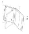
- FIG. 1 ( a ), FIG. 1 ( b ), FIG. 1 ( c ) and FIG. 1 ( d )are perspective views showing the operation according to the invention
- FIG. 2is a perspective view of the tilt/swivel mechanism of the flat panel display apparatus according to the invention.
- FIG. 3is an enlarged perspective view of the tilt/swivel mechanism of the flat panel display apparatus according to the invention.
- FIG. 4is an exploded perspective view of the tilt/swivel mechanism of the flat panel display apparatus according to the invention.
- FIG. 5is an exploded perspective view of the tilt/swivel mechanism of the flat panel display apparatus according to second preferred embodiment of the invention.
- FIG. 1 ( a ) to FIG. 1 ( d )are perspective views showing the operation according to the invention.
- FIG. 1 ( a )is a flat panel display apparatus 10 comprising a flat panel display 11 , a computer 13 and a tilt/swivel mechanism 12 (refer to FIG. 2) hidden between flat panel display 11 and computer 13 .
- the tilt/swivel mechanism 12permits a user to adjustably move the display panel in an up-and-down tilt direction along a connecting area 100 .
- a tilt/swivel mechanism 12 illustrated in the FIG. 1 ( b )permits a user to adjustably move the display panel in a right-and-left swivel direction along the connecting area 100 .
- FIG. 1 ( c )is a perspective view illustrating the condition as the flat panel display 11 swivels to a particular orientation, for example 180 degrees. At this point, the back of the flat panel display 11 faces forward.
- FIG. 1 ( d )is the condition followed by the FIG. 1 ( c ), where the flat panel display 11 tilts forward to be in a closed position with the computer 13 .
- the display screen of the flat panel display 11then faces upwards.
- the front, the side having the display screen of the flat panel display 11can further comprises input devices, for example a touch pad to enable the flat panel display 11 served as a electronic book.
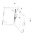
- FIG. 2illustrates the tilt/swivel mechanism 12 hidden between the flat panel display 11 and the computer 13 as shown in the FIG. 1 ( a ).
- the tilt/swivel mechanism 12comprises a yoke 21 and a swivel hinge 22 .
- the yoke 21is used for a user to adjustably move the flat panel display 11 in an up-and-down tilt direction along the connecting area.
- the swivel hinge 22is used for a user to adjustably move the flat panel display 11 in a right-and-left swivel direction along the connecting area.
- FIG. 3is an enlarged perspective view of the yoke 21 and the swivel hinge 22 .
- the swivel hinge 22comprises a yoke mounting arm 31 , swivel base 32 and a mounting base 33 .
- the yoke mounting arm 31is utilized to connect to the yoke 21 .
- the swivel base 32is located in the bottom edge of the yoke mounting arm 31 .
- the mounting base 33is secured on the computer 13 via mounting holes 34 .
- the mounting base 33holds the swivel base 32 to allow the swivel base 32 swivels therein. As a result, the swivel base 32 connected to the yoke mounting arm 31 swivels when the yoke mounting arm 31 swivels.
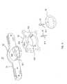
- FIG. 4is an exploded perspective view of the swivel hinge 22 ; comprising the yoke mounting arm 31 , the swivel base 32 and the mounting base 33 .
- the swivel base 32has a first cylinder 322 , where two grooves 321 parallel and opposite each other on the outer surface of the first cylinder 322 .
- the mounting base 33is secured on the computer 13 .
- the mounting base 33has a second cylinder 333 having a cable hole 332 formed at the center of the second cylinder 333 to hold the swivel base 32 .
- Two mounting slots 331are located in the cable hole 332 opposite each other.
- the elastic member 41comprises a projection 411 to be held in the mounting slots 331 .
- a ring 42is utilized to cover the mounting base 33 and secured to the swivel base 32 to avoid the elastic member 41 escape from the mounting slot 331 .
- each groove 321holds the projection 411 .
- Swivel action as mentioned aboverequires torsion that is provided by friction between the projection 411 of the elastic member 41 and the surface of the swivel base 32 .
- each groove 321holds the projection 411 and positions the swivel base 32 at a swivel angle of 180 degrees.
- the flat panel display 11then is positioned at swivel angle of 180 degrees either counterclockwise or clockwise. It follows that back instead of the front, the display screen, of the flat panel display 11 faces the user. The flat panel display then is tilted forward with the yoke 21 to be in a closed position with the computer 13 . When the flat panel display 11 is in a facing upward and closed position with the computer 13 , screen of the flat panel display 11 faces upwards.
- An application of said embodimentis an electronic book.
- FIG. 5is an exploded perspective view of the tilt/swivel mechanism of the flat panel display apparatus according to second preferred embodiment of the invention.
- a swivel hinge 50comprises a mounting member 51 , a yoke mounting arm 52 and a swivel base 53 .
- the mounting member 51is located on the computer and has a first cylinder with two grooves parallel and opposite each other on the outer surface of the first cylinder.
- the yoke mounting arm 52is utilized for connecting the yoke 21 to the connecting area 100 of the flat panel display 11 .
- the swivel base 53is located in the bottom edge of the yoke mounting arm 52 .
- swivel base 53is pivotally secured to the flat panel display 11 via yoke 21 .
- the swivel base 53has a second cylinder 533 .
- the second cylinder 533has a cable hole 531 formed at the center of the second cylinder 533 to hold the mounting member 51 , and two mounting slots 532 located in the cable hole 531 opposite each other.
- Each of the elastic members 54has a projection 541 to be held in the mounting slots 532 .
- Each groove 511holds the projection 541 and stops the swivel action while the swivel base 53 swivels to a particular orientation in the mounting member 511 .
- Swivel action as mentioned aboverequires torsion that is provided by friction between the projection 541 of the elastic member 54 and the surface of the swivel base 53 .
- each groove 321holds the projection 541 and positions the swivel base 53 at a swivel angle of 180 degrees.
- the flat panel display 11then is positioned at swivel angle of 180 degrees either counterclockwise or clockwise. It follows that back instead of the front, the display screen, of the flat panel display 11 faces the user. The flat panel display then is tilted forward with the yoke 21 to be in a closed position with the computer 13 . When the flat panel display 11 is in a facing upward and closed position with the computer 13 , screen of the flat panel display 11 faces upwards.
- An application of said embodimentis an electronic book.
Landscapes
- Engineering & Computer Science (AREA)
- Computer Hardware Design (AREA)
- Theoretical Computer Science (AREA)
- General Engineering & Computer Science (AREA)
- Physics & Mathematics (AREA)
- Human Computer Interaction (AREA)
- General Physics & Mathematics (AREA)
- Mathematical Physics (AREA)
- Mechanical Engineering (AREA)
- Devices For Indicating Variable Information By Combining Individual Elements (AREA)
Abstract
Description
Claims (20)
Priority Applications (1)
| Application Number | Priority Date | Filing Date | Title |
|---|---|---|---|
| US10/422,814US6876545B2 (en) | 2001-02-09 | 2003-04-25 | Flat panel display apparatus and tilt/swivel mechanism therein |
Applications Claiming Priority (3)
| Application Number | Priority Date | Filing Date | Title |
|---|---|---|---|
| TW090202022 | 2001-02-09 | ||
| TW90202022U | 2001-02-09 | ||
| TW090202022UTW495130U (en) | 2001-02-09 | 2001-02-09 | Flat display device and the rotatory structure thereof |
Related Child Applications (1)
| Application Number | Title | Priority Date | Filing Date |
|---|---|---|---|
| US10/422,814ContinuationUS6876545B2 (en) | 2001-02-09 | 2003-04-25 | Flat panel display apparatus and tilt/swivel mechanism therein |
Publications (2)
| Publication Number | Publication Date |
|---|---|
| US20020109962A1 US20020109962A1 (en) | 2002-08-15 |
| US6587333B2true US6587333B2 (en) | 2003-07-01 |
Family
ID=21681159
Family Applications (2)
| Application Number | Title | Priority Date | Filing Date |
|---|---|---|---|
| US09/858,520Expired - LifetimeUS6587333B2 (en) | 2001-02-09 | 2001-05-17 | Flat panel display apparatus and tilt/swivel mechanism therein |
| US10/422,814Expired - LifetimeUS6876545B2 (en) | 2001-02-09 | 2003-04-25 | Flat panel display apparatus and tilt/swivel mechanism therein |
Family Applications After (1)
| Application Number | Title | Priority Date | Filing Date |
|---|---|---|---|
| US10/422,814Expired - LifetimeUS6876545B2 (en) | 2001-02-09 | 2003-04-25 | Flat panel display apparatus and tilt/swivel mechanism therein |
Country Status (2)
| Country | Link |
|---|---|
| US (2) | US6587333B2 (en) |
| TW (1) | TW495130U (en) |
Cited By (45)
| Publication number | Priority date | Publication date | Assignee | Title |
|---|---|---|---|---|
| US20030193773A1 (en)* | 2002-04-12 | 2003-10-16 | Phil-Kyu Choi | Portable computer |
| US20040012920A1 (en)* | 2002-07-19 | 2004-01-22 | Kabushiki Kaisha Toshiba | Electronic apparatus having two housings coupled by hinge mechanism, one of which is reversible to the other |
| US20040024279A1 (en)* | 2002-07-31 | 2004-02-05 | Mason J. Bradley | In-drum pyrolysis system |
| US20040046487A1 (en)* | 2002-09-05 | 2004-03-11 | Olivera Argelio M. | Surgical console |
| US20040066614A1 (en)* | 2002-10-02 | 2004-04-08 | Samsung Electronics Co. Ltd. | Portable computer |
| US20040075971A1 (en)* | 2002-10-21 | 2004-04-22 | Wistron Corporation | Pivot-and-positioning assembly for an electronic device |
| US20040083577A1 (en)* | 2002-11-06 | 2004-05-06 | Lu Sheng-Nan | Hinge for a notebook computer |
| US20040090740A1 (en)* | 2002-11-11 | 2004-05-13 | Wistron Corporation | Electronic device with positioning unit |
| US20040141284A1 (en)* | 2003-01-16 | 2004-07-22 | Wen-Hsiang Chen | Rotatable display fixing module |
| US20040139578A1 (en)* | 2003-01-16 | 2004-07-22 | Kuo-Chang Yang | Swivel hinge with angular fixing structure |
| US20040160733A1 (en)* | 2003-02-14 | 2004-08-19 | Chen-Hua Hsu | Rotary axle structure for portable computers |
| US20040227045A1 (en)* | 2003-05-15 | 2004-11-18 | Lg Electronics Inc. | Swivel hinge assembly and electronic device having the same |
| US20040246357A1 (en)* | 2003-05-21 | 2004-12-09 | Premier Image Technology Corporation | Swivel structure for information product |
| US20050060843A1 (en)* | 2003-09-23 | 2005-03-24 | Tsung-Yung Hung | Hinge for notebook computer |
| US20050066477A1 (en)* | 2003-09-30 | 2005-03-31 | Kuo-Chang Yang | Swivel structure having direction indication |
| US20050069149A1 (en)* | 2003-09-30 | 2005-03-31 | Toshio Takahashi | Electronic apparatus capable of always executing proper noise canceling regardless of display screen state, and voice input method for the apparatus |
| US20050102799A1 (en)* | 2003-11-14 | 2005-05-19 | Tien-An Huang | Pivotal device |
| US20050125950A1 (en)* | 2003-12-10 | 2005-06-16 | Ding-Hone Su | Hinge with a rotating function |
| US20050141958A1 (en)* | 2003-12-24 | 2005-06-30 | Shih-Chun Huang | Knob lock mechanism with slot |
| US20050198780A1 (en)* | 2004-03-09 | 2005-09-15 | Compal Electronics, Inc. | Pivotal hinge mechanism used for portable computer |
| US20050207104A1 (en)* | 2004-03-22 | 2005-09-22 | Love John S | Multiaxial hinge assembly with rotational direction indicator |
| US20050246741A1 (en)* | 2004-04-02 | 2005-11-03 | Compal Electronics, Inc. | Pivotal hinge mechanism for mobile computer |
| US7024727B1 (en)* | 2004-10-15 | 2006-04-11 | Tatung Co., Ltd. | Coupling structure |
| US7027297B1 (en)* | 2005-03-28 | 2006-04-11 | Fujitsu Limited | Electronic apparatus and hinge unit |
| US20060163314A1 (en)* | 2005-01-25 | 2006-07-27 | Huan-Tsung Lin | Torsion adjusting module |
| US20060227154A1 (en)* | 2005-04-12 | 2006-10-12 | Hewlett-Packard Development Company, Lp | Electronic device display panel |
| US20060261227A1 (en)* | 2005-04-28 | 2006-11-23 | Bretford Manufacturing, Inc. | Universal mounting system for a flat panel display |
| US20070151076A1 (en)* | 2003-12-11 | 2007-07-05 | Hitoshi Sato | Two-shaft hinge mechanism enabling harness wiring |
| US20070217131A1 (en)* | 2006-03-15 | 2007-09-20 | Garry Kehr | Systems and methods for providing a movable computer display |
| US20070271733A1 (en)* | 2003-03-10 | 2007-11-29 | Kabushiki Kaisha Strawberry Corporation | Hinge Device |
| US20080001866A1 (en)* | 2006-06-28 | 2008-01-03 | Martin Michael M | Control Display Positioning System |
| US20080125761A1 (en)* | 2006-09-18 | 2008-05-29 | David Weston | Ophthalmic surgical console system |
| CN100453828C (en)* | 2003-12-11 | 2009-01-21 | 华硕电脑股份有限公司 | portable computer |
| US20090034173A1 (en)* | 2007-07-31 | 2009-02-05 | Donald Shaum | Electronic apparatus with multiple data input modes |
| US20110013351A1 (en)* | 2009-07-20 | 2011-01-20 | Mobile Monitor Technologies, Llc | Portable monitor |
| USD641049S1 (en)* | 2010-12-10 | 2011-07-05 | Nintendo Co., Ltd. | Portable electronic computer |
| USD643476S1 (en)* | 2010-06-11 | 2011-08-16 | Nintendo Co., Ltd. | Housing component of portable electronic computer |
| USD645521S1 (en)* | 2010-06-11 | 2011-09-20 | Nintentdo Co., Ltd. | Portable electronic computer |
| USD650448S1 (en)* | 2010-11-22 | 2011-12-13 | Nintendo Co., Ltd. | Electronic computer stand |
| USD650447S1 (en)* | 2010-06-11 | 2011-12-13 | Nintendo Co., Ltd. | Portable electronic computer |
| USD655351S1 (en) | 2010-06-11 | 2012-03-06 | Nintendo Co., Ltd. | Electronic computer stand |
| USD669541S1 (en)* | 2011-01-05 | 2012-10-23 | G.A.E.M.S., Inc. | Control panel of chassis for a video game console |
| USD699791S1 (en)* | 2012-08-09 | 2014-02-18 | Nintendo Co., Ltd. | Expansion controller for portable electronic computer |
| USD714246S1 (en)* | 2013-05-10 | 2014-09-30 | Panasonic Corporation | Mobile phone |
| USD728031S1 (en) | 2012-12-31 | 2015-04-28 | G.A.E.M.S., Inc. | Chassis for a video game console |
Families Citing this family (27)
| Publication number | Priority date | Publication date | Assignee | Title |
|---|---|---|---|---|
| US7129931B2 (en)* | 2001-09-14 | 2006-10-31 | Pappas Nicholas J | Multipurpose computer display system |
| KR100924038B1 (en) | 2002-08-29 | 2009-11-02 | 엘지전자 주식회사 | Keyboard removal device for portable hybrid computer |
| US7010834B2 (en)* | 2002-09-10 | 2006-03-14 | Nokia Corporation | Hinge assembly, and associated method, providing multiple axes of rotation |
| US6830456B2 (en)* | 2002-10-28 | 2004-12-14 | Hewlett-Packard Development Company, L.P. | Connector and apparatus including the same |
| JP2004197862A (en)* | 2002-12-19 | 2004-07-15 | Strawberry Corporation | Hinge device and electronic apparatus using the same |
| US20040143936A1 (en)* | 2003-01-28 | 2004-07-29 | Ming-Jer Hsu | Hinge structure for sales systems |
| JP2004293633A (en)* | 2003-03-26 | 2004-10-21 | Nec Corp | Folding portable terminal |
| TW578854U (en)* | 2003-04-11 | 2004-03-01 | Hon Hai Prec Ind Co Ltd | Hinge device |
| US7434774B1 (en)* | 2004-05-14 | 2008-10-14 | Engineered Network Systems, Inc. | Monitor mounting apparatus |
| US20060038102A1 (en)* | 2004-08-19 | 2006-02-23 | Chung-Wu Chia | Swivel ceiling fitting structure |
| DE102004041653B4 (en)* | 2004-08-27 | 2006-08-24 | Micro-Star International Co., Ltd., Jung He | Rotatable positioning device |
| US7189023B2 (en) | 2004-09-01 | 2007-03-13 | Micro-Star Int'l Co., Ltd. | Rotational positioning apparatus |
| TWI271610B (en)* | 2004-12-17 | 2007-01-21 | Tatung Co | Common rotate device for portable computer |
| KR100682634B1 (en)* | 2005-06-27 | 2007-02-15 | (주)케이티에프테크놀로지스 | Handheld terminal |
| US7257431B2 (en)* | 2005-07-28 | 2007-08-14 | Afreey Inc. | Electric swiveling mechanism for two axes |
| US20080034546A1 (en)* | 2006-07-10 | 2008-02-14 | Jia-Hao Hsu | Rotatable hinge |
| WO2008117451A1 (en)* | 2007-03-27 | 2008-10-02 | Fujitsu Limited | Electronic apparatus |
| US7559118B1 (en)* | 2008-05-13 | 2009-07-14 | Shin Zu Shing Co., Ltd. | Sag preventing hinge and its assembly |
| US8437126B2 (en)* | 2010-11-10 | 2013-05-07 | Lenovo (Singapore) Pte. Ltd. | Separable hinge assembly with two component device |
| TWI435007B (en)* | 2011-12-23 | 2014-04-21 | Wistron Corp | Biaxial pivoting mechanism and electronic device thereof |
| US9223351B2 (en)* | 2013-03-12 | 2015-12-29 | Google Inc. | Moveable display portion of a computing device |
| USD729257S1 (en) | 2013-03-15 | 2015-05-12 | Engineered Network Systems, Inc. | Swivel stand |
| USD781372S1 (en) | 2015-05-22 | 2017-03-14 | Engineered Network Systems, Llc | Payment terminal stand |
| CN106023677B (en)* | 2016-07-03 | 2019-07-09 | 深圳市中幼国际教育科技有限公司 | A kind of infant health e-book |
| CN106023676B (en)* | 2016-07-03 | 2019-02-15 | 深圳市中幼国际教育科技有限公司 | A kind of preschool education e-book |
| JP2018072934A (en)* | 2016-10-25 | 2018-05-10 | 富士通株式会社 | Terminal device |
| CN112445294B (en)* | 2019-08-27 | 2024-05-24 | 纬联电子科技(中山)有限公司 | Fixing assembly, shell assembly and electronic device |
Citations (16)
| Publication number | Priority date | Publication date | Assignee | Title |
|---|---|---|---|---|
| US4547027A (en)* | 1984-02-21 | 1985-10-15 | Itt Corporation | Modular swivel connector |
| US4640485A (en)* | 1984-06-08 | 1987-02-03 | International Business Machines Corporation | Adjustable support for display monitor |
| US4757388A (en) | 1985-08-09 | 1988-07-12 | Canon Kabushiki Kaisha | Camera with electronic view finder viewable from either behind or in front of the camera |
| US4919387A (en)* | 1989-03-06 | 1990-04-24 | Bell & Howell Publication Systems Company | Tilt and swivel support apparatus |
| US4986507A (en) | 1989-09-08 | 1991-01-22 | Arthur Chiang | Free positioning tilt unit |
| US5205017A (en)* | 1992-03-18 | 1993-04-27 | Jetta Computers Co., Ltd. | Notebook computer top cover mounting hardware |
| USD343168S (en)* | 1992-04-10 | 1994-01-11 | Sharp Kabushiki Kaisha | Computer |
| US5539463A (en) | 1993-08-24 | 1996-07-23 | Sony Corporation | Cassette eject mechanism, battery loading mechanism and mechanical chassis supporting mechanism |
| CN1155112A (en) | 1995-11-30 | 1997-07-23 | 富士通株式会社 | Display device with swing mechanism |
| US5715138A (en)* | 1995-10-19 | 1998-02-03 | Daewoo Electronics Co., Ltd. | Apparatus for providing a display with tilting and rotating movements with rack, pinion, and bevel gears |
| US5724704A (en) | 1995-04-06 | 1998-03-10 | Samsung Electronics Co., Ltd. | Detachable hinge device for portable notebook computer |
| US5739859A (en) | 1994-10-21 | 1998-04-14 | Sony Corporation | Video camera with a rotatably mounted viewfinder |
| US6189842B1 (en)* | 1999-06-21 | 2001-02-20 | Palo Alto Design Group | Tilt and swivel adjustment of flat panel display having detents for landscape and portrait positions and kickout for preventing contact between flat panel display and base |
| US6347433B1 (en)* | 1999-06-18 | 2002-02-19 | Cema Technologies, Inc. | Flat panel display tilt and swivel mechanism |
| US6510049B2 (en)* | 2000-01-06 | 2003-01-21 | Rosen Products Llc | Adjustable display monitor unit |
| US6522530B2 (en)* | 2000-08-04 | 2003-02-18 | Samsung Electronics Co., Ltd. | Computer system having a monitor movably coupled to a main body |
Family Cites Families (7)
| Publication number | Priority date | Publication date | Assignee | Title |
|---|---|---|---|---|
| US5206790A (en)* | 1991-07-11 | 1993-04-27 | Zeos International, Ltd. | Pivot and swivel mechanism for lap top display |
| US5335142A (en)* | 1992-12-21 | 1994-08-02 | Ast Research, Inc. | Portable computer display tilt/swivel mechanism |
| KR100212313B1 (en)* | 1996-11-06 | 1999-08-02 | 윤종용 | Lcd display device |
| KR19980034365A (en)* | 1996-11-06 | 1998-08-05 | 김광호 | Balanced LCD Display |
| CN2352086Y (en) | 1998-11-18 | 1999-12-08 | 蔡源挥 | Improvement of Christmas tree branch joint structure |
| CN2411511Y (en) | 2000-03-24 | 2000-12-20 | 伦飞电脑实业股份有限公司 | Base of thin display |
| CN2419639Y (en) | 2000-05-17 | 2001-02-14 | 王炯中 | Cash register monitor stand swivel support structure |
- 2001
- 2001-02-09TWTW090202022Upatent/TW495130U/ennot_activeIP Right Cessation
- 2001-05-17USUS09/858,520patent/US6587333B2/ennot_activeExpired - Lifetime
- 2003
- 2003-04-25USUS10/422,814patent/US6876545B2/ennot_activeExpired - Lifetime
Patent Citations (16)
| Publication number | Priority date | Publication date | Assignee | Title |
|---|---|---|---|---|
| US4547027A (en)* | 1984-02-21 | 1985-10-15 | Itt Corporation | Modular swivel connector |
| US4640485A (en)* | 1984-06-08 | 1987-02-03 | International Business Machines Corporation | Adjustable support for display monitor |
| US4757388A (en) | 1985-08-09 | 1988-07-12 | Canon Kabushiki Kaisha | Camera with electronic view finder viewable from either behind or in front of the camera |
| US4919387A (en)* | 1989-03-06 | 1990-04-24 | Bell & Howell Publication Systems Company | Tilt and swivel support apparatus |
| US4986507A (en) | 1989-09-08 | 1991-01-22 | Arthur Chiang | Free positioning tilt unit |
| US5205017A (en)* | 1992-03-18 | 1993-04-27 | Jetta Computers Co., Ltd. | Notebook computer top cover mounting hardware |
| USD343168S (en)* | 1992-04-10 | 1994-01-11 | Sharp Kabushiki Kaisha | Computer |
| US5539463A (en) | 1993-08-24 | 1996-07-23 | Sony Corporation | Cassette eject mechanism, battery loading mechanism and mechanical chassis supporting mechanism |
| US5739859A (en) | 1994-10-21 | 1998-04-14 | Sony Corporation | Video camera with a rotatably mounted viewfinder |
| US5724704A (en) | 1995-04-06 | 1998-03-10 | Samsung Electronics Co., Ltd. | Detachable hinge device for portable notebook computer |
| US5715138A (en)* | 1995-10-19 | 1998-02-03 | Daewoo Electronics Co., Ltd. | Apparatus for providing a display with tilting and rotating movements with rack, pinion, and bevel gears |
| CN1155112A (en) | 1995-11-30 | 1997-07-23 | 富士通株式会社 | Display device with swing mechanism |
| US6347433B1 (en)* | 1999-06-18 | 2002-02-19 | Cema Technologies, Inc. | Flat panel display tilt and swivel mechanism |
| US6189842B1 (en)* | 1999-06-21 | 2001-02-20 | Palo Alto Design Group | Tilt and swivel adjustment of flat panel display having detents for landscape and portrait positions and kickout for preventing contact between flat panel display and base |
| US6510049B2 (en)* | 2000-01-06 | 2003-01-21 | Rosen Products Llc | Adjustable display monitor unit |
| US6522530B2 (en)* | 2000-08-04 | 2003-02-18 | Samsung Electronics Co., Ltd. | Computer system having a monitor movably coupled to a main body |
Non-Patent Citations (2)
| Title |
|---|
| English Language Abstracts of Chinese Patent Appln. Nos. 2411511Y, 2352986Y, 1155112A and 2419639Y. |
| Opposition No. 09240300060 Dated Feb. 25, 2003 with attachments copy of Chinese Search Report. |
Cited By (76)
| Publication number | Priority date | Publication date | Assignee | Title |
|---|---|---|---|---|
| US20030193773A1 (en)* | 2002-04-12 | 2003-10-16 | Phil-Kyu Choi | Portable computer |
| US6867961B2 (en)* | 2002-04-12 | 2005-03-15 | Samsung Electronics Co., Ltd. | Portable computer |
| US20040012920A1 (en)* | 2002-07-19 | 2004-01-22 | Kabushiki Kaisha Toshiba | Electronic apparatus having two housings coupled by hinge mechanism, one of which is reversible to the other |
| US6850407B2 (en)* | 2002-07-19 | 2005-02-01 | Kabushiki Kaisha Toshiba | Electronic apparatus having two housings coupled by hinge mechanism, one of which is reversible to the other |
| US20040024279A1 (en)* | 2002-07-31 | 2004-02-05 | Mason J. Bradley | In-drum pyrolysis system |
| US20040046487A1 (en)* | 2002-09-05 | 2004-03-11 | Olivera Argelio M. | Surgical console |
| US7044568B2 (en)* | 2002-09-05 | 2006-05-16 | Alcon, Inc. | Surgical console |
| US20040066614A1 (en)* | 2002-10-02 | 2004-04-08 | Samsung Electronics Co. Ltd. | Portable computer |
| US6963485B2 (en)* | 2002-10-02 | 2005-11-08 | Samsung Electronics Co., Ltd. | Portable computer |
| US6958902B2 (en)* | 2002-10-21 | 2005-10-25 | Wistron Corporation | Pivot-and-positioning assembly for an electronic device |
| US20040075971A1 (en)* | 2002-10-21 | 2004-04-22 | Wistron Corporation | Pivot-and-positioning assembly for an electronic device |
| US6742221B2 (en)* | 2002-11-06 | 2004-06-01 | Shin Zu Shing Co., Ltd. | Hinge for a notebook computer |
| US20040083577A1 (en)* | 2002-11-06 | 2004-05-06 | Lu Sheng-Nan | Hinge for a notebook computer |
| US20040090740A1 (en)* | 2002-11-11 | 2004-05-13 | Wistron Corporation | Electronic device with positioning unit |
| US7100876B2 (en)* | 2002-11-11 | 2006-09-05 | Wistron Corporation | Electronic device with positioning unit |
| US7319583B2 (en) | 2002-11-11 | 2008-01-15 | Wistron Corporation | Electronic device with positioning unit |
| US6883206B2 (en)* | 2003-01-16 | 2005-04-26 | Quanta Computer Inc. | Swivel hinge with angular fixing structure |
| US6912122B2 (en)* | 2003-01-16 | 2005-06-28 | Quanta Computer Inc. | Rotatable display fixing module |
| US20040141284A1 (en)* | 2003-01-16 | 2004-07-22 | Wen-Hsiang Chen | Rotatable display fixing module |
| US20040139578A1 (en)* | 2003-01-16 | 2004-07-22 | Kuo-Chang Yang | Swivel hinge with angular fixing structure |
| US20040160733A1 (en)* | 2003-02-14 | 2004-08-19 | Chen-Hua Hsu | Rotary axle structure for portable computers |
| US6798646B2 (en)* | 2003-02-14 | 2004-09-28 | Lite-On Technology Corporation | Rotary axle structure for portable computers |
| US20070271733A1 (en)* | 2003-03-10 | 2007-11-29 | Kabushiki Kaisha Strawberry Corporation | Hinge Device |
| US7581291B2 (en)* | 2003-03-10 | 2009-09-01 | Kabushiki Kaisha Strawberry Corporation | Hinge device |
| US20040227045A1 (en)* | 2003-05-15 | 2004-11-18 | Lg Electronics Inc. | Swivel hinge assembly and electronic device having the same |
| US7308733B2 (en)* | 2003-05-15 | 2007-12-18 | Lg Electronics Inc. | Swivel hinge assembly and electronic device having the same |
| US7475452B2 (en)* | 2003-05-21 | 2009-01-13 | Premier Image Technology Corporation | Swivel structure for information product |
| US20040246357A1 (en)* | 2003-05-21 | 2004-12-09 | Premier Image Technology Corporation | Swivel structure for information product |
| US20050060843A1 (en)* | 2003-09-23 | 2005-03-24 | Tsung-Yung Hung | Hinge for notebook computer |
| US20050069149A1 (en)* | 2003-09-30 | 2005-03-31 | Toshio Takahashi | Electronic apparatus capable of always executing proper noise canceling regardless of display screen state, and voice input method for the apparatus |
| US20050066477A1 (en)* | 2003-09-30 | 2005-03-31 | Kuo-Chang Yang | Swivel structure having direction indication |
| US7191492B2 (en)* | 2003-09-30 | 2007-03-20 | Quanta Computer Inc. | Swivel structure having direction indication |
| US8189818B2 (en)* | 2003-09-30 | 2012-05-29 | Kabushiki Kaisha Toshiba | Electronic apparatus capable of always executing proper noise canceling regardless of display screen state, and voice input method for the apparatus |
| US20050102799A1 (en)* | 2003-11-14 | 2005-05-19 | Tien-An Huang | Pivotal device |
| US7047598B2 (en)* | 2003-11-14 | 2006-05-23 | Asustek Computer Inc. | Pivotal device |
| US20050125950A1 (en)* | 2003-12-10 | 2005-06-16 | Ding-Hone Su | Hinge with a rotating function |
| US7614118B2 (en)* | 2003-12-11 | 2009-11-10 | Mitsubishi Steel Mfg. Co., Ltd. | Two-shaft hinge mechanism enabling harness wiring |
| US20070151076A1 (en)* | 2003-12-11 | 2007-07-05 | Hitoshi Sato | Two-shaft hinge mechanism enabling harness wiring |
| CN100453828C (en)* | 2003-12-11 | 2009-01-21 | 华硕电脑股份有限公司 | portable computer |
| US20050141958A1 (en)* | 2003-12-24 | 2005-06-30 | Shih-Chun Huang | Knob lock mechanism with slot |
| US7101109B2 (en)* | 2003-12-24 | 2006-09-05 | Quanta Computer, Inc. | Knob lock mechanism with slot |
| US20050198780A1 (en)* | 2004-03-09 | 2005-09-15 | Compal Electronics, Inc. | Pivotal hinge mechanism used for portable computer |
| US7159279B2 (en)* | 2004-03-09 | 2007-01-09 | Compal Electronic, Inc. | Pivotal hinge mechanism used for portable computer |
| US7133280B2 (en)* | 2004-03-22 | 2006-11-07 | Gateway Inc. | Multiaxial hinge assembly with rotational direction indicator |
| US20050207104A1 (en)* | 2004-03-22 | 2005-09-22 | Love John S | Multiaxial hinge assembly with rotational direction indicator |
| US7234204B2 (en) | 2004-04-02 | 2007-06-26 | Compal Electronics, Inc. | Pivotal hinge mechanism for mobile computer |
| US20050246741A1 (en)* | 2004-04-02 | 2005-11-03 | Compal Electronics, Inc. | Pivotal hinge mechanism for mobile computer |
| US7024727B1 (en)* | 2004-10-15 | 2006-04-11 | Tatung Co., Ltd. | Coupling structure |
| US20060081738A1 (en)* | 2004-10-15 | 2006-04-20 | Tatung Co., Ltd. | Coupling structure |
| US20060163314A1 (en)* | 2005-01-25 | 2006-07-27 | Huan-Tsung Lin | Torsion adjusting module |
| US7027297B1 (en)* | 2005-03-28 | 2006-04-11 | Fujitsu Limited | Electronic apparatus and hinge unit |
| US20060227154A1 (en)* | 2005-04-12 | 2006-10-12 | Hewlett-Packard Development Company, Lp | Electronic device display panel |
| US7436674B2 (en) | 2005-04-12 | 2008-10-14 | Hewlett-Packard Development Company, L.P. | Electronic device display panel |
| US7600728B2 (en) | 2005-04-28 | 2009-10-13 | Bretford Manufacturing, Inc. | Universal mounting system for a flat panel display |
| US20060261227A1 (en)* | 2005-04-28 | 2006-11-23 | Bretford Manufacturing, Inc. | Universal mounting system for a flat panel display |
| US20070217131A1 (en)* | 2006-03-15 | 2007-09-20 | Garry Kehr | Systems and methods for providing a movable computer display |
| US20080001866A1 (en)* | 2006-06-28 | 2008-01-03 | Martin Michael M | Control Display Positioning System |
| US8310468B2 (en) | 2006-06-28 | 2012-11-13 | Novartis Ag | Control display positioning system |
| US20080125761A1 (en)* | 2006-09-18 | 2008-05-29 | David Weston | Ophthalmic surgical console system |
| US8262553B2 (en) | 2006-09-18 | 2012-09-11 | Novartis Ag | Ophthalmic surgical console system |
| US20090034173A1 (en)* | 2007-07-31 | 2009-02-05 | Donald Shaum | Electronic apparatus with multiple data input modes |
| US7656661B2 (en) | 2007-07-31 | 2010-02-02 | Donald Shaum | Electronic apparatus with multiple data input modes |
| US20110013351A1 (en)* | 2009-07-20 | 2011-01-20 | Mobile Monitor Technologies, Llc | Portable monitor |
| USD666679S1 (en) | 2010-06-11 | 2012-09-04 | Nintendo Co., Ltd. | Portable electronic computer |
| USD650447S1 (en)* | 2010-06-11 | 2011-12-13 | Nintendo Co., Ltd. | Portable electronic computer |
| USD655351S1 (en) | 2010-06-11 | 2012-03-06 | Nintendo Co., Ltd. | Electronic computer stand |
| USD656555S1 (en)* | 2010-06-11 | 2012-03-27 | Nintendo Co., Ltd. | Electronic computer stand |
| USD645521S1 (en)* | 2010-06-11 | 2011-09-20 | Nintentdo Co., Ltd. | Portable electronic computer |
| USD643476S1 (en)* | 2010-06-11 | 2011-08-16 | Nintendo Co., Ltd. | Housing component of portable electronic computer |
| USD650448S1 (en)* | 2010-11-22 | 2011-12-13 | Nintendo Co., Ltd. | Electronic computer stand |
| USD641049S1 (en)* | 2010-12-10 | 2011-07-05 | Nintendo Co., Ltd. | Portable electronic computer |
| USD669541S1 (en)* | 2011-01-05 | 2012-10-23 | G.A.E.M.S., Inc. | Control panel of chassis for a video game console |
| USD680594S1 (en) | 2011-01-05 | 2013-04-23 | G.A.E.M.S., Inc. | Control panel of chassis for a video game console |
| USD699791S1 (en)* | 2012-08-09 | 2014-02-18 | Nintendo Co., Ltd. | Expansion controller for portable electronic computer |
| USD728031S1 (en) | 2012-12-31 | 2015-04-28 | G.A.E.M.S., Inc. | Chassis for a video game console |
| USD714246S1 (en)* | 2013-05-10 | 2014-09-30 | Panasonic Corporation | Mobile phone |
Also Published As
| Publication number | Publication date |
|---|---|
| US6876545B2 (en) | 2005-04-05 |
| TW495130U (en) | 2002-07-11 |
| US20040008477A1 (en) | 2004-01-15 |
| US20020109962A1 (en) | 2002-08-15 |
Similar Documents
| Publication | Publication Date | Title |
|---|---|---|
| US6587333B2 (en) | Flat panel display apparatus and tilt/swivel mechanism therein | |
| TWI669593B (en) | Adjustable display housing assembly | |
| US7478789B2 (en) | Pivoting mechanism for stand and electronic apparatus | |
| US6912122B2 (en) | Rotatable display fixing module | |
| US7283355B2 (en) | Portable computer | |
| US6778196B2 (en) | Mounting a display panel in a computer | |
| US6867961B2 (en) | Portable computer | |
| US8125771B2 (en) | Electronic apparatus | |
| US7200428B2 (en) | Portable terminal | |
| US8031463B2 (en) | Electronic apparatus emitting light through a unitary transparent base chassis | |
| CN102884777B (en) | Method and apparatus for double slider device with tilting display | |
| US20050082440A1 (en) | Display apparatus | |
| US20030042385A1 (en) | Liquid crystal display with a ball-and-socket mounting joint | |
| US6781821B2 (en) | Electronic apparatus | |
| CN110285297B (en) | Supporting device | |
| JP3934902B2 (en) | Electronics | |
| US6751090B1 (en) | Rotatable display fixing module | |
| US20060039104A1 (en) | Notebook computer with adjustable monitor | |
| US7191492B2 (en) | Swivel structure having direction indication | |
| KR100393617B1 (en) | Telephone with cantilever beam type cradle and cradled handset therein | |
| US6822851B2 (en) | Electronic device | |
| JP2003256078A (en) | Electronic equipment | |
| JP4917517B2 (en) | Slide rotation mounting unit and mobile phone | |
| KR20040102794A (en) | Tilting control apparatus for portable computer | |
| JPH11153832A (en) | Camera provided with clip and camera apparatus |
Legal Events
| Date | Code | Title | Description |
|---|---|---|---|
| AS | Assignment | Owner name:ACER INC., TAIWAN Free format text:ASSIGNMENT OF ASSIGNORS INTEREST;ASSIGNORS:TSENG, PETER;CHIAN, CHU-HSIAN;CHUNG, HSU SHIH;AND OTHERS;REEL/FRAME:011816/0878;SIGNING DATES FROM 20010425 TO 20010502 | |
| AS | Assignment | Owner name:WISTRON CORPORATION, CHINA Free format text:ASSIGNMENT OF ASSIGNORS INTEREST;ASSIGNOR:ACER INCORPORATED;REEL/FRAME:013456/0722 Effective date:20020923 Owner name:ACER INCORPORATED, TAIWAN Free format text:ASSIGNMENT OF ASSIGNORS INTEREST;ASSIGNOR:ACER INCORPORATED;REEL/FRAME:013456/0722 Effective date:20020923 | |
| STCF | Information on status: patent grant | Free format text:PATENTED CASE | |
| CC | Certificate of correction | ||
| FPAY | Fee payment | Year of fee payment:4 | |
| AS | Assignment | Owner name:WISTRON CORPORATION,TAIWAN Free format text:ASSIGNMENT OF ASSIGNORS INTEREST;ASSIGNOR:CHEN, CHIA-HUI;REEL/FRAME:024252/0915 Effective date:20100407 Owner name:ACER INCORPORATED,TAIWAN Free format text:ASSIGNMENT OF ASSIGNORS INTEREST;ASSIGNOR:CHEN, CHIA-HUI;REEL/FRAME:024252/0915 Effective date:20100407 | |
| CC | Certificate of correction | ||
| FPAY | Fee payment | Year of fee payment:8 | |
| FPAY | Fee payment | Year of fee payment:12 |