US6586327B2 - Fabrication of semiconductor devices - Google Patents
Fabrication of semiconductor devicesDownload PDFInfo
- Publication number
- US6586327B2 US6586327B2US09/965,622US96562201AUS6586327B2US 6586327 B2US6586327 B2US 6586327B2US 96562201 AUS96562201 AUS 96562201AUS 6586327 B2US6586327 B2US 6586327B2
- Authority
- US
- United States
- Prior art keywords
- series
- layers
- pits
- channels
- substrate
- Prior art date
- Legal status (The legal status is an assumption and is not a legal conclusion. Google has not performed a legal analysis and makes no representation as to the accuracy of the status listed.)
- Expired - Lifetime
Links
Images


Classifications
- H—ELECTRICITY
- H10—SEMICONDUCTOR DEVICES; ELECTRIC SOLID-STATE DEVICES NOT OTHERWISE PROVIDED FOR
- H10D—INORGANIC ELECTRIC SEMICONDUCTOR DEVICES
- H10D86/00—Integrated devices formed in or on insulating or conducting substrates, e.g. formed in silicon-on-insulator [SOI] substrates or on stainless steel or glass substrates
- H10D86/201—Integrated devices formed in or on insulating or conducting substrates, e.g. formed in silicon-on-insulator [SOI] substrates or on stainless steel or glass substrates the substrates comprising an insulating layer on a semiconductor body, e.g. SOI
- H—ELECTRICITY
- H01—ELECTRIC ELEMENTS
- H01L—SEMICONDUCTOR DEVICES NOT COVERED BY CLASS H10
- H01L21/00—Processes or apparatus adapted for the manufacture or treatment of semiconductor or solid state devices or of parts thereof
- H01L21/70—Manufacture or treatment of devices consisting of a plurality of solid state components formed in or on a common substrate or of parts thereof; Manufacture of integrated circuit devices or of parts thereof
- H01L21/71—Manufacture of specific parts of devices defined in group H01L21/70
- H01L21/76—Making of isolation regions between components
- H01L21/762—Dielectric regions, e.g. EPIC dielectric isolation, LOCOS; Trench refilling techniques, SOI technology, use of channel stoppers
- H01L21/76224—Dielectric regions, e.g. EPIC dielectric isolation, LOCOS; Trench refilling techniques, SOI technology, use of channel stoppers using trench refilling with dielectric materials
- H01L21/76229—Concurrent filling of a plurality of trenches having a different trench shape or dimension, e.g. rectangular and V-shaped trenches, wide and narrow trenches, shallow and deep trenches
- H—ELECTRICITY
- H01—ELECTRIC ELEMENTS
- H01L—SEMICONDUCTOR DEVICES NOT COVERED BY CLASS H10
- H01L21/00—Processes or apparatus adapted for the manufacture or treatment of semiconductor or solid state devices or of parts thereof
- H01L21/70—Manufacture or treatment of devices consisting of a plurality of solid state components formed in or on a common substrate or of parts thereof; Manufacture of integrated circuit devices or of parts thereof
- H01L21/71—Manufacture of specific parts of devices defined in group H01L21/70
- H01L21/76—Making of isolation regions between components
- H01L21/762—Dielectric regions, e.g. EPIC dielectric isolation, LOCOS; Trench refilling techniques, SOI technology, use of channel stoppers
- H01L21/76224—Dielectric regions, e.g. EPIC dielectric isolation, LOCOS; Trench refilling techniques, SOI technology, use of channel stoppers using trench refilling with dielectric materials
- H01L21/76232—Dielectric regions, e.g. EPIC dielectric isolation, LOCOS; Trench refilling techniques, SOI technology, use of channel stoppers using trench refilling with dielectric materials of trenches having a shape other than rectangular or V-shape, e.g. rounded corners, oblique or rounded trench walls
- H—ELECTRICITY
- H10—SEMICONDUCTOR DEVICES; ELECTRIC SOLID-STATE DEVICES NOT OTHERWISE PROVIDED FOR
- H10B—ELECTRONIC MEMORY DEVICES
- H10B20/00—Read-only memory [ROM] devices
- H10B20/20—Programmable ROM [PROM] devices comprising field-effect components
- H10B20/25—One-time programmable ROM [OTPROM] devices, e.g. using electrically-fusible links
- H—ELECTRICITY
- H10—SEMICONDUCTOR DEVICES; ELECTRIC SOLID-STATE DEVICES NOT OTHERWISE PROVIDED FOR
- H10D—INORGANIC ELECTRIC SEMICONDUCTOR DEVICES
- H10D86/00—Integrated devices formed in or on insulating or conducting substrates, e.g. formed in silicon-on-insulator [SOI] substrates or on stainless steel or glass substrates
- H10D86/01—Manufacture or treatment
- H—ELECTRICITY
- H10—SEMICONDUCTOR DEVICES; ELECTRIC SOLID-STATE DEVICES NOT OTHERWISE PROVIDED FOR
- H10D—INORGANIC ELECTRIC SEMICONDUCTOR DEVICES
- H10D86/00—Integrated devices formed in or on insulating or conducting substrates, e.g. formed in silicon-on-insulator [SOI] substrates or on stainless steel or glass substrates
- H10D86/40—Integrated devices formed in or on insulating or conducting substrates, e.g. formed in silicon-on-insulator [SOI] substrates or on stainless steel or glass substrates characterised by multiple TFTs
- H10D86/60—Integrated devices formed in or on insulating or conducting substrates, e.g. formed in silicon-on-insulator [SOI] substrates or on stainless steel or glass substrates characterised by multiple TFTs wherein the TFTs are in active matrices
Definitions
- the inventionrelates to microelectronic devices and there fabrication.
- a substantial portion of the cost of microelectronic device fabricationis attributable to the capital cost of lithography equipment.
- Such equipmentproduces integrated circuits by drawing patterns on a substrate using commonly known methods, such as photolithography, e-beam lithography, as well as many others.
- Photolithographyrequires the use of expensive patterned masks. Exposure of the substrate to UV radiation through the mask pattern, followed by etching, forms circuit traces on the substrate. A microscopic electronic device is formed through repetition of this elaborate process so as to generate a series of adjacent stacked circuit layers.
- the cost of fabricationincreases as the device geometry becomes more complex and the feature size diminishes.
- e-beam lithographymay be needed to create the masks, and deep UV (X-ray) exposure systems may be necessary to perform the substrate lithography.
- X-rayX-ray
- e-beam lithographyan electron beam is used to draw the features on the surface of the substrate of the masks. This process is very slow because the features are typically drawn sequentially by a single electron beam.
- multiple lithography stepsmust be aligned to one another for the resulting device to be operational.
- Another method of microelectronic device fabricationis the “dual-damascene” process. Basically, this technique involves etching a trench in a substrate, etching a deeper channel (i.e., a via) within the trench, electrochemically plating an active layer within the trench and the via, and removing the overfill by chemical mechanical polishing (CMP).
- CMPchemical mechanical polishing
- a single material layeri.e., copper and, possibly, a barrier and/or sticking layer
- the trenches and viasare patterned photolithographically.
- the present inventionis directed to a microelectronic device fabrication process which, in some embodiments, does not require the use of masks or lithography. This is accomplished through creation of a recessed pattern on a substrate. A series of layers is applied to the substrate surface and the recessed surfaces, and the substrate surface may then be planarized (e.g., by polishing) to a desired degree. Planarization removes one or more of the deposited layers, or a portion of a layer, from the substrate surface but not from within the recessed pattern. Consequently, the depth of a recessed feature determines the number of layers that will remain therein at the conclusion of processing.
- the inventionis directed to fabricating a microelectronic device on a substrate having a recessed contour pattern.
- the patternis defined (e.g., by molding, as discussed below, or by etching or other conventional processes) a series of layers each having a predetermined electrical property is applied.
- the deviceis planarized (e.g., by polishing) to remove one or more layers thus far applied. Planarization does not affect deposited material within the recessed pattern.
- the devicesis further processed, typically by etching, to further remove material from one or more layers thus far applied and exposed through planarization.
- the stacked layersare disposed within the contour pattern, and some of the layers also reside on the substrate. The layers cooperate to form the microelectronic device.
- the inventionin another aspect, relates to fabrication of an electronic devices using a molded substrate. This approach avoids the need to etch a microscopic pattern into the substrate.
- a form having a raised topology complementary to a desired microscopic pattern of featuresis created.
- the formis applied to a moldable substrate to impose the pattern therein, i.e., to create a recessed pattern complementary to the raised topology.
- a series of layers having desired electrical propertiesis applied to the recessed pattern, thereby creating the electronic device.
- the formis fabricated by etching a pattern into a master substrate, plating the patterned master substrate, and electroforming on a metal plate a topology complementary to the etched pattern to serve as a form.
- the formmay be used to impose the original pattern onto a moldable substrate by, e.g., injection molding.
- the patternmay, for example, comprise pyramidal, square and/or round pits and square, rounded and/or V-groove channels.
- the inventionis used to fabricate a memory device in accordance with any of U.S. Pat. Nos. 3,245,051, 5,673,218 and 5,889,694.
- the recessed patternincludes a first series of channels running in a first direction and a second series of channels running in a second direction substantially perpendicular to the first direction. These are imposed (e.g., by molding, as discussed above) into a non-conducting substrate.
- the first-series channels and the second-series channelscross at crossing points, and pits are located at the crossing points.
- the applied layersform nonlinear elements (e.g., diodes) in some of the pits, depending on their depths.
- Each nonlinear elementconnects a first-series channel with a second-series channel.
- the nonlinear elementsare distributed among the pits in a scheme that defines the data contents of the memory.
- a connection between crossing channelssignifies one binary bit state (e.g., zero) and no connection signifies the other binary bit state (e.g., one).
- FIG. 1is a flow chart of an embodiment of a method of the present invention
- FIG. 2Ais a top view of a contoured substrate surface constructed in accordance with the invention.
- FIG. 2Bis a sectional view of the substrate shown in FIG. 2A, taken along line 2 B— 2 B;
- FIG. 2Cis another sectional view of the substrate shown in FIG. 2A, taken along line 2 C— 2 C;
- FIG. 3is a flow chart of an embodiment of the step of applying layers as shown in FIG. 1;
- FIG. 4is a flow chart of an embodiment of the step of the applying the layers of FIG. 3;
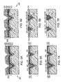
- FIG. 5Ais a sectional view of the substrate shown in FIG. 2A taken along line 2 B— 2 B, after deposition of the layers;
- FIG. 5Bis a sectional view of the substrate shown in FIG. 2A taken along line 2 C— 2 C, after deposition of the layers;
- FIG. 6Ais a sectional view of the substrate shown in FIG. 2A taken along line 2 B— 2 B, after planarization;
- FIG. 6Bis a sectional view of the substrate shown in FIG. 2A taken along line 2 C— 2 C, after planarization;
- FIG. 7Ais a sectional view of the substrate shown in FIG. 2A taken along line 2 B— 2 B, post metal etching;
- FIG. 7Bis a sectional view of the substrate shown in FIG. 2A taken along line 2 C— 2 C, post metal etching;
- FIG. 8Ais a sectional view of the substrate shown in FIG. 2A taken along line 2 B— 2 B, after silicon etching;
- FIG. 8Bis a sectional view of the substrate shown in FIG. 2A taken along line 2 C— 2 C, after silicon etching;
- FIG. 9Ais a sectional view of the substrate shown in FIG. 2A taken along line 2 B— 2 B, after an insulation layer is applied;
- FIG. 9Bis a sectional view of the substrate shown in FIG. 2A taken along line 2 C— 2 C, after an insulation layer is applied;
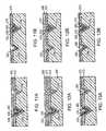
- FIG. 10Ais a sectional view of the substrate shown in FIG. 2A taken along line 2 B— 2 B, after planarization;
- FIG. 10Bis a sectional view of the substrate shown in FIG. 2A taken along line 2 C— 2 C, after planarization;
- FIG. 11Ais a sectional view of the substrate shown in FIG. 2A taken along line 2 B— 2 B, after the barrier layer is removed by etching;
- FIG. 11Bis a side view along line 2 C of FIG. 2A showing an embodiment of the after the barrier layer is removed by etching;
- FIG. 12Ais a sectional view of the substrate shown in FIG. 2A taken along line 2 B— 2 B, after metal deposition;
- FIG. 12Bis a sectional view of the substrate shown in FIG. 2A taken along line 2 C— 2 C, after metal deposition;
- FIG. 13Ais a sectional view of the substrate shown in FIG. 2A taken along line 2 B— 2 B, after planarization;
- FIG. 13Bis a sectional view of the substrate shown in FIG. 2A taken along line 2 C— 2 C, after planarization;
- FIG. 14illustrates a representative embodiment of a mask.
- Devices in accordance with the inventionmay be fabricated using a molding process, which obviates the need to etch a recessed pattern into each substrate. Such a process is illustrated in FIG. 1 .
- a “master” substrateis etched with the recessed pattern (step 110 ).
- This master substrateis then plated (e.g., nickel sputtered) (step 120 ) in a manner similar to conventional CD and DVD fabrication.
- the metal-plated masteris electroformed to create a form having a raised topology complementary to the recessed pattern of the substrate (step 130 ).
- Electroformingis the process of replicating the surface of a master by plating directly over it. A plating material is applied until the desired thickness is achieved.
- the remaining cavity blockis back-filled for strength and then mounted in a frame.
- the recessesbecome raised features.
- Variations on the electroforming of the master copycould include depositing on that master copy material intended to appear in the face of the mold, following which the mold is chemically or physically separated from the master following deposition.
- the form, thus fabricated,is used to create a new substrate from a moldable material (step 140 ).
- injection moldingis used to produce new substrates having the same recessed pattern as the master.
- the new substrateis typically formed out of plastic or glass although other moldable materials (typically, although not necessarily, electrically nonconductive) are suitable.
- a series of layersis applied to the new substrate (step 150 ). These layers provide the desired electrical properties of the microelectronic device.
- FIG. 2Ais a top view of a portion of a substrate 200 having a microscopic recessed pattern constructed in accordance with the present invention.
- substrate 200can be formed from the master by injection molding or itself could be the master used to create the form; alternatively, the etched substrate can itself be used as the basis for a microelectronic device.
- the following discussiondescribes formation of a representative portion of a microelectronic device in which conductive pathways either establish connections to adjacent pathways through nonlinear devices (such as diodes, transistors, etc.) or do not establish connections.
- a series of rows 210 and columns 220is etched into substrate 200 .
- rows 210 and columns 220are substantially perpendicular to each other and intersect at a matrix of pits 230 having varying depths.
- the depths of pits 230are determined by the sizes (i.e., the areas) of the squares defining the tops of the pits 230 at the substrate surface. By selecting different square sizes, one can select an equal number of depths for the resulting pyramidal pits. The formation of such structures is well known to those versed in the art of semiconductor and MEMS fabrication.
- rows 210 and columns 220are formed using a silicon etch in KOH.
- the result of the etching processis a plurality of large pits 230 a and small pits 230 b , referred to generally as pits 230 .
- pits 230are pyramidal in shape, and rows 210 and columns 220 are V-grooves, although other shapes are possible.
- an etch rate of KOH at a concentration of 44 gm in 100 ml H 2 O, at a temperature of 85° C.is 1.4 ⁇ m/min in the ⁇ 100> crystal direction whereas in the ⁇ 111> crystal direction it is only about 0.0035 ⁇ m/min.
- rows 210 and columns 220are controlled through the selection of their widths. As illustrated in the figures, to provide increased conductivity, two side-by-side columns 220 can be used that are each one half the width of the rows 210 . This results in pairs of columns 220 with approximately the same total area as the rows 210 . In this embodiment, rows 210 are approximately twice as deep as columns 220 . The depth of a pit 230 determines whether or not a connection is formed between a row and column where they cross.
- FIGS. 2B and 2CThe result is shown in the sectional views of FIGS. 2B and 2C. Because the columns 220 and rows 210 are V-grooves, the portion of row 210 visible in FIG. 2 B and the portion of column 220 visible in FIG. 2C are receding, i.e., angled into the plane of the figure. Similarly, the visible rear walls of the pits 230 in FIGS. 2B and 2C also recede, and show the entry of a relatively shallow column 220 or a relatively deep row 210 into the pit. The row 210 is nearly as deep as the small pit 230 b.
- an etch mask for such an arraywould not look like the final etch pattern as shown in the top view of FIG. 2 A. This is because the etch stop for KOH is on a ⁇ 111> plane that is intact; if the plane is interrupted by another etched surface the etch will continue until an intact ⁇ 111> surface is reached or the entire silicon area is removed. A circular KOH etch will undercut its mask until a square pyramidal pit is formed.
- etching the etch pattern shown in FIG. 2Acan be achieved in several ways.
- One approachis to etch the row 210 and column 220 features with a first KOH etch.
- the surfaceis then masked so as to expose only the squares which form the pits 230 .
- the square mask openingsshould be the size of the pits 230 as they are desired to be at a known distance below the surface.
- the surfaceis then etched anisotropically to this depth by an etch which will create vertical side walls (such as an RIE etch).
- a timed KOH etchis next performed such that the remaining depths are etched in the pits 230 .
- the top areas of these square pyramidal pits(the portion above the bottom of the RIE etch) will etch wider than their original RIE etched squared as they seek the ⁇ 111> plane.
- this etch-back of the top areas of the pitswill cause the pits 230 to etch into the ends of the rectangles, thereby forming the desired surface topology.
- This latter etchis timed such that the interconnects are fully merged with the squares; that is, the connection of an interconnect with a square does not have any shallow seam at the point of connection (as would occur with an under-etch) and also is not so over-etched that the depth of the interconnect is impacted in its middle.
- Other mask patternswhich form both the square pits and the interconnects in a single timed KOH etch are possible.
- the desired depths of the rows 210 and columns 220can be controlled through the selection of the row and column widths.
- the substrate 200 illustrated in FIGS. 2A-2C and described abovecan be formed on a conventional crystalline silicon wafer.
- This wafermay be crystalline silicon that is either intrinsic or lightly doped such that the circuits constructed thereon will be electrically isolated from each other by virtue of their being reversed biased with respect to this substrate.
- the substrate 200may be processed for the formation of an insulating layer either by oxide growth or by material deposition.
- the etched substratemay be used directly, it is preferred to follow the procedure outlined in FIG. 1 and use the etched substrate as a master.
- SOGspun-on-glass
- a polyimide materialcould be deposited on the surface of the electroformed master and then delaminated in a way similar to the SOG approach.
- Some polyimidescan be released from a surface by soaking the polyimide coated electroformed master in deionized water (DI water) or, if the electroformed master is coated with a thin layer of silicon dioxide, by soaking the polyimide-coated electroformed master in hydrofluoric acid (HF). Both of these approaches require that the electroformed master not be made of materials that will react with DI or HF, respectively, and such materials are well known to those skilled in the art.
- DI waterdeionized water
- HFhydrofluoric acid
- the illustrated series of stepsis used to form a memory device in which connections between crossing rows and channels (by means of nonlinear devices) signify one binary state, while the absence of a connection indicates the other state.
- a series of layersis applied to the replicated substrate (step 300 ).
- the layersare planarized back to the surface of replicated substrate 200 ′ (step 310 ).
- a timed metal etchis performed (step 320 ) followed by a timed silicon etch (step 330 ).
- An insulation layeris applied (step 340 ) and then planarized (step 350 ). Any barrier material remaining from the original application of the layers and subsequent planarization (steps 300 and 310 ) is etched away (step 360 ).
- a metal layeris deposited (step 370 ) and planarized (step 380 ), creating the memory device.
- step 300Deposition of the series of layers collectively indicated at 500 (step 300 ) is illustrated in more detail in FIG. 4, FIG. 5A, and FIG. 5 B. (It should be noted that the ensuing pairs of figures represent the same sections illustrated in FIGS. 2B and 2C.) With reference to those figures, if replicated substrate 200 ′ is not insulative, an insulation layer is applied (step 400 , not shown in FIGS. 5 A and 5 B).
- a 1000 ⁇ bottom metal layer 510is deposited (step 410 ) followed by a 250 ⁇ N + amorphous silicon (N + ⁇ SI:H) layer 520 (step 420 ), a 1000 ⁇ layer 530 of ⁇ SI:H (step 430 ), a 1000 ⁇ top metal layer 540 (step 440 ), and a barrier layer 550 (step 450 ), respectively.
- Bottom metal layer 510 and top metal layer 540can be tungsten, chromium or molybdenum, and barrier layer 550 can be silicon nitride.
- the choice of metals for top metal layer 510 and bottom metal layer 540 and their respective thicknessesis not critical to the invention as long as the functional requirements of the device are maintained.
- bottom metal layer 510can be made of any material that will form an ohmic contact with the layer 520 directly above it. Additionally, bottom metal layer 510 should be thick enough to carry an electrical current adequate to provide a desired operational speed with respect to any circuit capacitances.
- Layer 520can be any suitable semiconductor that will form an ohmic contact connection between bottom metal layer 510 and the layer 530 directly above it. Layer 520 should be thick enough to prevent bottom metal layer 510 and layer 530 from interacting in a nonlinear way (i.e., a non-rectifying contact).
- Layer 530can be any material that will form a rectifying contact with top metal layer 540 (e.g., amorphous silicon, the alpha-T 6 material manufactured by Lucent, or organic semiconductor materials including those used to make organic light emitting diodes (oLEDs)). Layer 530 should be thick enough to create an adequate junction depth for proper operation of the rectifying contact.
- Top metal layer 540can be any material the will form a rectifying contact with the layer 530 directly below it.
- the layers 500are applied using chemical-vapor deposition (CVD), although other conventional deposition methods are possible.
- TFTthin-film transistors
- the deposition of amorphous siliconwill occur at 200 to 400° C. or higher.
- the metal on which it is depositedshould remain stable during deposition so as to not react unfavorably with the deposited silicon. Some metals, such as aluminum, will react continuously with the grain boundaries of the amorphous silicon and are unsuitable even for the top metal unless additional barrier metal is added.
- FIGS. 6A and 6Bshow the result of simultaneously planarizing all of the materials to coincide with the height of substrate 200 .
- this planarizationis accomplished with a combination of CMP and etching.
- a CMP polishing stepremoves barrier layer 550 and top metal layer 540 to the highest point of the amorphous silicon layer 530 .
- a timed etchis performed to reduce the height of the amorphous silicon layer 530 to coincide with the height of substrate 200 ′.
- the CMP polishing stepis repeated so as to remove any remaining top metal layer 550 or bottom metal layer 510 above the substrate 200 ′ surface.
- planarization methodscan be used, for example, oxide planarization wherein an oxide material (or one that etched at nearly the same rate as the surface material to be planarized) is deposited on the surface in a non-conformal manner so that its surface is flat. As this material is etched, the oxide as well as the surface material is reduced in thickness until the desired planar depth is reached. This technique, as well as others, are known to those skilled in the art.
- the timed metal etchremoves any of the exposed metal layers 540 and 510 not protected by remaining barrier layer 550 or the silicon layers 520 and 530 , as depicted in FIGS. 7A and 7B. As a result, recesses 560 are formed within pits 230 a ′ and 230 b ′. Additionally, metal layers 540 and 510 exposed within columns 220 are removed, thereby isolating the conductive rows 210 .
- the timed silicon etchremoves any exposed silicon of silicon layers 530 and 520 .
- the only remaining siliconresides in larger pits 230 a ′.
- the larger pits 230 a ′define where the rows 210 and columns 220 cross to form nonlinear elements.
- Larger pits 230 a ′each retain a layer of N + amorphous silicon 520 and a layer of amorphous silicon 530 cooperating to form diodes (e.g., Schottky diodes).
- the N + doped layer 520forms an ohmic contact with the lower metal layer 510 in the rows 210 and the undoped amorphous silicon layer 530 forms a Schottky barrier with the top metal layer 540 , which becomes connected to the columns 220 as described below.
- an insulation layere.g., silicon dioxide
- PECVDplasma enhanced chemical vapor deposition
- sputteringresults in the structure shown in FIGS. 9A and 9B.
- the pyramidal shape of pits 230 ′result in barrier layer 550 not being entirely covered (because the insulator material does not easily get underneath barrier layer 550 ). If the pits 230 have straight (vertical) walls rather than angled walls, or if the deposition runs somewhat more conformally, the sides of the barrier material might be coated with a very thin layer of insulator material. This would then be corrected by removing it with a quick etch dip timed to remove this side wall coating without significantly reducing the bulk of this deposited layer.
- PECVDplasma enhanced chemical vapor deposition
- Insulation layer 570 extending above substrate 200 ′is planarized back to the level of substrate 200 ′.
- FIG. 10 A and FIG. 10Bshow the non-insulated barrier layers 550 exposed within larger pits 230 a ′. Etching away the exposed barrier layer 550 (step 360 ) exposes the top metal layer 540 in deep pits 230 a ′ as shown in FIGS. 11A and 11B. Alternatively, this polishing step could be omitted and the barrier just etched away which will also remove the insulator material from above the barrier material as is commonly done in a liftoff process. Following the removal of the barrier material, the metal on top of the silicon material in the deeper pits 230 a ′ (i.e., those in which it is desired to form a nonlinear element) is exposed.
- a final metal layer 580is deposited (step 370 ) on top of insulation layer 570 .
- a portion of the final metal layer 580extends above substrate 200 ′ as depicted in FIGS. 12A and 12B. That portion is planarized back to the level of substrate 200 ′.
- the resulting conductive metal rows 210 and columns 220can now be recognized, and the microelectronic circuit is shown in FIGS. 13A and 13B.
- a material layer suitable for forming a programmable conducting pathsuch as a fusible link, an anti-fusible link, a resistively alterable material (e.g., a phase change material), or the like, an array of diodes constructed according to the present invention and U.S. Pat. No.
- the substrate featuresare shown here as having been formed with the KOH etch as described above but could have been formed with a series of RIE etches (in which case the features would have a more squared-off shape) or chemical etches (in which the features would have a more inverted mushroom-cap shape) that are timed to control the depth of the etch.
- Squared-off or mushroom-cap featurescould be used just as well because it is the depth of the pits and the width at the surface (not their width at the bottom) that is the critical factor for constructing devices according to the present invention.
- a conformal depositionshould be used to ensure that a connection is made between the bottom of one feature and up the side wall to the bottom of an adjacent feature.
- FIG. 14Another technique for forming the substrate features is shown in FIG. 14 .
- an etch mask 600is created that includes a feature 610 a or 610 b (referred to generally as 610 ) for each of the pits 230 but not the channels connecting the pits 230 .
- These mask features 610can be formed in one of two sizes corresponding to the two different pit depths.
- FIG. 14shows the features 610 having a circular form; however, a mask could be created in which the features 610 have a square form oriented at a 45° angle to the resulting etched pits (i.e., a square-oriented mask opening within diamond-oriented pits). The orientation of the rows and columns of the mask are turned 45° to the ⁇ 111> silicon crystal orientation. As shown in FIG.
- a KOH etchwill undercut the mask shape to find the pyramidal etch stop, except that this undercut will merge with the comers of the adjacent features and form the channels between the pits.
- the larger features 610 bwill result in deeper pits while the smaller features 610 a will result in shallower pits.
- the features 610 that are closeri.e., the circles forming the rows
- the features 610 that are closerwill have deeper channels while the more widely spaced features (i.e., the circles forming the columns) will have shallower channels.
- the circle sizes and spacingare selected such that any two adjacent circles, whether they are both large or small or one of each size, result in a channel depth that causes retention only of the appropriate remaining material layers in the channel between them.
- the pit depthsare controlled by the natural etch stop while the channel depths are controlled by timing the etch.
- an initial RIE etchas described above, may be performed. If the substrate is generated by e-beam lithography, the two mask feature sizes can be selected by varying the power of the e-beam whereby a large circle feature would be drawn with a higher e-beam power than a smaller circle feature. Characterization of a focus-exposure test will determine the appropriate power levels for the two feature sizes.
- the present inventionis based on the approach that layers deposited on a contoured substrate can be processed through planarizations and etches such that the material left behind forms a circuit in which the feature are self-aligning.
- the different height of the surface prior to material depositiondetermines which materials are exposed at any given point on the surface following planarization.
- the exposed surfacescan be further selectively processed through etching. Pits having several different widths and depths can be envisioned whereby the process can be repeated to produce pits comprising multiple layers of material enabling the formation of more complex devices. For example, with the addition of a thin dielectric layer, a TFT-like transistor could be incorporated.
- the present inventioncan include other process steps. For example, where there is a metal area formed in the bottom of a feature that is to become a bonding pad, it may be desirable to deposit the top metal on the surface without the insulating material 570 and semiconducting materials 520 and 530 in series with that bottom metal and top metal. To accomplish this, a shadow mask can be used to block the deposition of the insulating and semiconducting materials in the area of the bonding pad. The top metal will now make a direct connection to the bottom metal in this area. This shadow masking can be accomplished because a bonding pad feature can have an area of 50 ⁇ m to 200 ⁇ m or more, thereby making alignment of the mask to the substrate possible without advanced lithography and alignment tools.
- Shadow mask stepsmay be used to fabricate an array of field effect transistors (FETs) placed together in an area of the substrate such that a thin oxide or some other dielectric can be deposited upon the gate regions without having that material be deposited upon other areas of the substrate.
- FETsfield effect transistors
- low-resolution photolithographycan be used (instead of a shadow mask) followed by a liftoff.
Landscapes
- Engineering & Computer Science (AREA)
- Microelectronics & Electronic Packaging (AREA)
- Condensed Matter Physics & Semiconductors (AREA)
- General Physics & Mathematics (AREA)
- Manufacturing & Machinery (AREA)
- Computer Hardware Design (AREA)
- Physics & Mathematics (AREA)
- Power Engineering (AREA)
- Semiconductor Memories (AREA)
- Drying Of Semiconductors (AREA)
- Internal Circuitry In Semiconductor Integrated Circuit Devices (AREA)
- Weting (AREA)
- Electrodes Of Semiconductors (AREA)
Abstract
Description
Claims (31)
Priority Applications (3)
| Application Number | Priority Date | Filing Date | Title |
|---|---|---|---|
| US09/965,622US6586327B2 (en) | 2000-09-27 | 2001-09-27 | Fabrication of semiconductor devices |
| US10/459,699US7183206B2 (en) | 2000-09-27 | 2003-06-11 | Fabrication of semiconductor devices |
| US11/655,470US7507663B2 (en) | 2000-09-27 | 2007-01-19 | Fabrication of semiconductor devices |
Applications Claiming Priority (2)
| Application Number | Priority Date | Filing Date | Title |
|---|---|---|---|
| US23585300P | 2000-09-27 | 2000-09-27 | |
| US09/965,622US6586327B2 (en) | 2000-09-27 | 2001-09-27 | Fabrication of semiconductor devices |
Related Child Applications (2)
| Application Number | Title | Priority Date | Filing Date |
|---|---|---|---|
| US10/459,699Continuation-In-PartUS7183206B2 (en) | 2000-09-27 | 2003-06-11 | Fabrication of semiconductor devices |
| US10/459,699ContinuationUS7183206B2 (en) | 2000-09-27 | 2003-06-11 | Fabrication of semiconductor devices |
Publications (2)
| Publication Number | Publication Date |
|---|---|
| US20020086542A1 US20020086542A1 (en) | 2002-07-04 |
| US6586327B2true US6586327B2 (en) | 2003-07-01 |
Family
ID=22887168
Family Applications (3)
| Application Number | Title | Priority Date | Filing Date |
|---|---|---|---|
| US09/965,622Expired - LifetimeUS6586327B2 (en) | 2000-09-27 | 2001-09-27 | Fabrication of semiconductor devices |
| US10/459,699Expired - LifetimeUS7183206B2 (en) | 2000-09-27 | 2003-06-11 | Fabrication of semiconductor devices |
| US11/655,470Expired - Fee RelatedUS7507663B2 (en) | 2000-09-27 | 2007-01-19 | Fabrication of semiconductor devices |
Family Applications After (2)
| Application Number | Title | Priority Date | Filing Date |
|---|---|---|---|
| US10/459,699Expired - LifetimeUS7183206B2 (en) | 2000-09-27 | 2003-06-11 | Fabrication of semiconductor devices |
| US11/655,470Expired - Fee RelatedUS7507663B2 (en) | 2000-09-27 | 2007-01-19 | Fabrication of semiconductor devices |
Country Status (6)
| Country | Link |
|---|---|
| US (3) | US6586327B2 (en) |
| EP (1) | EP1320872A2 (en) |
| JP (1) | JP2004523881A (en) |
| CN (1) | CN100435347C (en) |
| AU (1) | AU2001294817A1 (en) |
| WO (1) | WO2002027768A2 (en) |
Cited By (27)
| Publication number | Priority date | Publication date | Assignee | Title |
|---|---|---|---|---|
| US20030006527A1 (en)* | 2001-06-22 | 2003-01-09 | Rabolt John F. | Method of fabricating micron-and submicron-scale elastomeric templates for surface patterning |
| US20030190803A1 (en)* | 2002-04-05 | 2003-10-09 | Harchanko John S. | System and method for analog replication of microdevices having a desired surface contour |
| US20050067675A1 (en)* | 2003-08-19 | 2005-03-31 | Shepard Daniel Robert | Molded substrate for topograpy based lithography |
| US20050170639A1 (en)* | 2004-01-30 | 2005-08-04 | Ping Mei | Forming a semiconductor device |
| US20060019504A1 (en)* | 2004-07-21 | 2006-01-26 | Taussig Carl P | Forming a plurality of thin-film devices |
| US20060060885A1 (en)* | 2003-12-11 | 2006-03-23 | Xerox Corporation | Nanoparticle deposition process |
| US7183206B2 (en) | 2000-09-27 | 2007-02-27 | Contour Semiconductor, Inc. | Fabrication of semiconductor devices |
| US20070111366A1 (en)* | 2005-04-26 | 2007-05-17 | Odom Teri W | Mesoscale pyramids, arrays and methods of preparation |
| US20070230243A1 (en)* | 2006-03-28 | 2007-10-04 | Eric Nestler | Memory array with readout isolation |
| US20070247890A1 (en)* | 2006-02-15 | 2007-10-25 | Shepard Daniel R | Nano-vacuum-tubes and their application in storage devices |
| US20080016414A1 (en)* | 2000-06-22 | 2008-01-17 | Contour Semiconductor, Inc. | Low Cost High Density Rectifier Matrix Memory |
| US20080023694A1 (en)* | 2006-07-25 | 2008-01-31 | Chi Mei El Corp. | Display device and method of manufacturing the same |
| US7376008B2 (en) | 2003-08-07 | 2008-05-20 | Contour Seminconductor, Inc. | SCR matrix storage device |
| US20080197342A1 (en)* | 2007-02-15 | 2008-08-21 | Chi Mei El Corp. | Display device and method of manufacturing the same |
| US20090029493A1 (en)* | 2005-04-29 | 2009-01-29 | David Todd Emerson | Methods of Forming Light Emitting Devices with Active Layers that Extend Into Opened Pits |
| US20090109726A1 (en)* | 2007-10-29 | 2009-04-30 | Shepard Daniel R | Non-linear conductor memory |
| US20090161420A1 (en)* | 2007-12-19 | 2009-06-25 | Shepard Daniel R | Field-emitter-based memory array with phase-change storage devices |
| US20090225621A1 (en)* | 2008-03-05 | 2009-09-10 | Shepard Daniel R | Split decoder storage array and methods of forming the same |
| US20090296445A1 (en)* | 2008-06-02 | 2009-12-03 | Shepard Daniel R | Diode decoder array with non-sequential layout and methods of forming the same |
| US20100049149A1 (en)* | 2003-09-22 | 2010-02-25 | Rucinski Paul J | Devices and Methods for Delivering Active Agents to Target Sites |
| US20100047995A1 (en)* | 2008-08-18 | 2010-02-25 | Apodaca Mac D | Method for forming self-aligned phase-change semiconductor diode memory |
| US20100085830A1 (en)* | 2008-10-07 | 2010-04-08 | Shepard Daniel R | Sequencing Decoder Circuit |
| US20100096610A1 (en)* | 2008-10-17 | 2010-04-22 | Wang Hsingya A | Phase-change material memory cell |
| US20100165727A1 (en)* | 2008-12-31 | 2010-07-01 | Shepard Daniel R | Phase change material memory having no erase cycle |
| US20100232200A1 (en)* | 2009-03-10 | 2010-09-16 | Shepard Daniel R | Vertical switch three-dimensional memory array |
| USRE41733E1 (en) | 1996-03-05 | 2010-09-21 | Contour Semiconductor, Inc. | Dual-addressed rectifier storage device |
| US11098233B2 (en) | 2012-12-04 | 2021-08-24 | William Marsh Rice University | Carbonaceous nanoparticles as conductivity enhancement additives to water-in-oil emulsions, oil-in-water emulsions and oil-based wellbore fluids |
Families Citing this family (18)
| Publication number | Priority date | Publication date | Assignee | Title |
|---|---|---|---|---|
| US6713408B1 (en)* | 2000-12-14 | 2004-03-30 | Louisiana Tech University Foundation, Inc. | Method of producing silica micro-structures from x-ray lithography of SOG materials |
| KR100661347B1 (en)* | 2004-10-27 | 2006-12-27 | 삼성전자주식회사 | Micro thin film structure and MEMS switch using the same and method for manufacturing them |
| FR2880191B1 (en)* | 2004-12-23 | 2007-03-16 | St Microelectronics Sa | ACHIEVING TRENCHES OR WELLS HAVING DIFFERENT DESTINATIONS IN A SEMICONDUCTOR SUBSTRATE |
| KR100670538B1 (en)* | 2004-12-30 | 2007-01-16 | 매그나칩 반도체 유한회사 | Image sensor and its manufacturing method that can improve optical characteristics |
| CN101287857B (en)* | 2005-05-05 | 2011-07-13 | H.C.施塔克有限公司 | Coating method for manufacturing or reprocessing sputtering targets and X-ray anodes |
| US8802191B2 (en)* | 2005-05-05 | 2014-08-12 | H. C. Starck Gmbh | Method for coating a substrate surface and coated product |
| US7479671B2 (en)* | 2006-08-29 | 2009-01-20 | International Business Machines Corporation | Thin film phase change memory cell formed on silicon-on-insulator substrate |
| US20080078268A1 (en)* | 2006-10-03 | 2008-04-03 | H.C. Starck Inc. | Process for preparing metal powders having low oxygen content, powders so-produced and uses thereof |
| JP5377319B2 (en)* | 2006-11-07 | 2013-12-25 | ハー.ツェー.スタルク ゲゼルシャフト ミット ベシュレンクテル ハフツング | Substrate coating method and coated product |
| US20080145688A1 (en) | 2006-12-13 | 2008-06-19 | H.C. Starck Inc. | Method of joining tantalum clade steel structures |
| US8157914B1 (en) | 2007-02-07 | 2012-04-17 | Chien-Min Sung | Substrate surface modifications for compositional gradation of crystalline materials and associated products |
| US8197894B2 (en) | 2007-05-04 | 2012-06-12 | H.C. Starck Gmbh | Methods of forming sputtering targets |
| US7799600B2 (en)* | 2007-05-31 | 2010-09-21 | Chien-Min Sung | Doped diamond LED devices and associated methods |
| US8246903B2 (en) | 2008-09-09 | 2012-08-21 | H.C. Starck Inc. | Dynamic dehydriding of refractory metal powders |
| US8043655B2 (en)* | 2008-10-06 | 2011-10-25 | H.C. Starck, Inc. | Low-energy method of manufacturing bulk metallic structures with submicron grain sizes |
| US9412568B2 (en) | 2011-09-29 | 2016-08-09 | H.C. Starck, Inc. | Large-area sputtering targets |
| US20160315256A1 (en)* | 2013-12-13 | 2016-10-27 | Hewlett Packard Enterprise Development Lp | V-shape resistive memory element |
| US10818778B2 (en) | 2017-11-27 | 2020-10-27 | Taiwan Semiconductor Manufacturing Co., Ltd. | Heterogeneous semiconductor device substrates with high quality epitaxy |
Citations (16)
| Publication number | Priority date | Publication date | Assignee | Title |
|---|---|---|---|---|
| US3245051A (en) | 1960-11-16 | 1966-04-05 | John H Robb | Information storage matrices |
| US3683722A (en)* | 1969-10-09 | 1972-08-15 | Edward Alexander Pears | Press tools and dies |
| US4369564A (en)* | 1979-10-29 | 1983-01-25 | American Microsystems, Inc. | VMOS Memory cell and method for making same |
| US5244837A (en) | 1993-03-19 | 1993-09-14 | Micron Semiconductor, Inc. | Semiconductor electrical interconnection methods |
| JPH0766438A (en) | 1993-08-30 | 1995-03-10 | Tonen Corp | Method for manufacturing substrate for photoelectric conversion device |
| US5673218A (en) | 1996-03-05 | 1997-09-30 | Shepard; Daniel R. | Dual-addressed rectifier storage device |
| US5834324A (en) | 1996-09-18 | 1998-11-10 | Kabushiki Kaisha Toshiba | Field emission cold-cathode device and method of manufacturing the same |
| US5859964A (en) | 1996-10-25 | 1999-01-12 | Advanced Micro Devices, Inc. | System and method for performing real time data acquisition, process modeling and fault detection of wafer fabrication processes |
| JPH11305055A (en) | 1998-04-22 | 1999-11-05 | Sharp Corp | Method of manufacturing optical waveguide and method of manufacturing master master plate for manufacturing optical waveguide |
| US6118135A (en) | 1995-06-07 | 2000-09-12 | Micron Technology, Inc. | Three-dimensional container diode for use with multi-state material in a non-volatile memory cell |
| US6117720A (en) | 1995-06-07 | 2000-09-12 | Micron Technology, Inc. | Method of making an integrated circuit electrode having a reduced contact area |
| US6190929B1 (en)* | 1999-07-23 | 2001-02-20 | Micron Technology, Inc. | Methods of forming semiconductor devices and methods of forming field emission displays |
| US6268280B1 (en) | 1996-07-12 | 2001-07-31 | Kabushiki Kaisha Toshiba | Semiconductor device using dual damascene technology and method for manufacturing the same |
| US6274497B1 (en)* | 1999-11-25 | 2001-08-14 | Taiwan Semiconductor Manufacturing Co., Ltd. | Copper damascene manufacturing process |
| US6309580B1 (en)* | 1995-11-15 | 2001-10-30 | Regents Of The University Of Minnesota | Release surfaces, particularly for use in nanoimprint lithography |
| US20020042027A1 (en)* | 1998-10-09 | 2002-04-11 | Chou Stephen Y. | Microscale patterning and articles formed thereby |
Family Cites Families (18)
| Publication number | Priority date | Publication date | Assignee | Title |
|---|---|---|---|---|
| US324051A (en)* | 1885-08-11 | Wilhblm umland | ||
| US5173442A (en)* | 1990-07-23 | 1992-12-22 | Microelectronics And Computer Technology Corporation | Methods of forming channels and vias in insulating layers |
| JPH06215423A (en)* | 1992-11-26 | 1994-08-05 | Canon Inc | Optical recording medium substrate sheet manufacturing method and manufacturing apparatus, stamper manufacturing method, and photomask manufacturing method |
| JPH07334866A (en)* | 1994-04-14 | 1995-12-22 | Pioneer Electron Corp | Optical disk and its production |
| WO1999039394A1 (en) | 1998-02-02 | 1999-08-05 | Uniax Corporation | X-y addressable electric microswitch arrays and sensor matrices employing them |
| US6815774B1 (en)* | 1998-10-29 | 2004-11-09 | Mitsubishi Materials Silicon Corporation | Dielectrically separated wafer and method of the same |
| JP2000133704A (en)* | 1998-10-29 | 2000-05-12 | Mitsubishi Materials Silicon Corp | Dielectric isolation wafer and its manufacture |
| US6256767B1 (en) | 1999-03-29 | 2001-07-03 | Hewlett-Packard Company | Demultiplexer for a molecular wire crossbar network (MWCN DEMUX) |
| JP2001217245A (en)* | 2000-02-04 | 2001-08-10 | Sharp Corp | Electronic component and manufacturing method thereof |
| WO2002027768A2 (en) | 2000-09-27 | 2002-04-04 | Nüp2 Incorporated | Fabrication of semiconductor devices |
| US6817531B2 (en) | 2001-03-07 | 2004-11-16 | Hewlett-Packard Development Company, L.P. | Apparatus and methods for marking content of memory storage devices |
| US7039780B2 (en) | 2001-06-05 | 2006-05-02 | Hewlett-Packard Development Company, L.P. | Digital camera memory system |
| US6567295B2 (en) | 2001-06-05 | 2003-05-20 | Hewlett-Packard Development Company, L.P. | Addressing and sensing a cross-point diode memory array |
| US6385075B1 (en) | 2001-06-05 | 2002-05-07 | Hewlett-Packard Company | Parallel access of cross-point diode memory arrays |
| US6552409B2 (en) | 2001-06-05 | 2003-04-22 | Hewlett-Packard Development Company, Lp | Techniques for addressing cross-point diode memory arrays |
| US6646912B2 (en) | 2001-06-05 | 2003-11-11 | Hewlett-Packard Development Company, Lp. | Non-volatile memory |
| US6478231B1 (en) | 2001-06-29 | 2002-11-12 | Hewlett Packard Company | Methods for reducing the number of interconnects to the PIRM memory module |
| US6599796B2 (en) | 2001-06-29 | 2003-07-29 | Hewlett-Packard Development Company, L.P. | Apparatus and fabrication process to reduce crosstalk in pirm memory array |
- 2001
- 2001-09-27WOPCT/US2001/030296patent/WO2002027768A2/enactiveApplication Filing
- 2001-09-27JPJP2002531468Apatent/JP2004523881A/enactivePending
- 2001-09-27AUAU2001294817Apatent/AU2001294817A1/ennot_activeAbandoned
- 2001-09-27EPEP01975498Apatent/EP1320872A2/ennot_activeWithdrawn
- 2001-09-27USUS09/965,622patent/US6586327B2/ennot_activeExpired - Lifetime
- 2001-09-27CNCNB01819463XApatent/CN100435347C/ennot_activeExpired - Fee Related
- 2003
- 2003-06-11USUS10/459,699patent/US7183206B2/ennot_activeExpired - Lifetime
- 2007
- 2007-01-19USUS11/655,470patent/US7507663B2/ennot_activeExpired - Fee Related
Patent Citations (16)
| Publication number | Priority date | Publication date | Assignee | Title |
|---|---|---|---|---|
| US3245051A (en) | 1960-11-16 | 1966-04-05 | John H Robb | Information storage matrices |
| US3683722A (en)* | 1969-10-09 | 1972-08-15 | Edward Alexander Pears | Press tools and dies |
| US4369564A (en)* | 1979-10-29 | 1983-01-25 | American Microsystems, Inc. | VMOS Memory cell and method for making same |
| US5244837A (en) | 1993-03-19 | 1993-09-14 | Micron Semiconductor, Inc. | Semiconductor electrical interconnection methods |
| JPH0766438A (en) | 1993-08-30 | 1995-03-10 | Tonen Corp | Method for manufacturing substrate for photoelectric conversion device |
| US6118135A (en) | 1995-06-07 | 2000-09-12 | Micron Technology, Inc. | Three-dimensional container diode for use with multi-state material in a non-volatile memory cell |
| US6117720A (en) | 1995-06-07 | 2000-09-12 | Micron Technology, Inc. | Method of making an integrated circuit electrode having a reduced contact area |
| US6309580B1 (en)* | 1995-11-15 | 2001-10-30 | Regents Of The University Of Minnesota | Release surfaces, particularly for use in nanoimprint lithography |
| US5673218A (en) | 1996-03-05 | 1997-09-30 | Shepard; Daniel R. | Dual-addressed rectifier storage device |
| US6268280B1 (en) | 1996-07-12 | 2001-07-31 | Kabushiki Kaisha Toshiba | Semiconductor device using dual damascene technology and method for manufacturing the same |
| US5834324A (en) | 1996-09-18 | 1998-11-10 | Kabushiki Kaisha Toshiba | Field emission cold-cathode device and method of manufacturing the same |
| US5859964A (en) | 1996-10-25 | 1999-01-12 | Advanced Micro Devices, Inc. | System and method for performing real time data acquisition, process modeling and fault detection of wafer fabrication processes |
| JPH11305055A (en) | 1998-04-22 | 1999-11-05 | Sharp Corp | Method of manufacturing optical waveguide and method of manufacturing master master plate for manufacturing optical waveguide |
| US20020042027A1 (en)* | 1998-10-09 | 2002-04-11 | Chou Stephen Y. | Microscale patterning and articles formed thereby |
| US6190929B1 (en)* | 1999-07-23 | 2001-02-20 | Micron Technology, Inc. | Methods of forming semiconductor devices and methods of forming field emission displays |
| US6274497B1 (en)* | 1999-11-25 | 2001-08-14 | Taiwan Semiconductor Manufacturing Co., Ltd. | Copper damascene manufacturing process |
Non-Patent Citations (6)
| Title |
|---|
| "Aries Process Notes: Oxide Planarization", Materials Research Corporation, 2 pages. |
| Chip Scale Review Online, http://www.chipscalereview.com/issues/0301/techReport.html, printed on Sep. 17, 2001, 3 pages. |
| Copy of International Search Report for PCT/US01/30296 (4 pgs.). |
| Damascene, http://courses.nus.edu.sg/course/phyweets/Projects99/Copper/damascene.htm, printed on Sep. 26, 2001, 8 pages. |
| Dual-Damascene: Overcoming Process Issues-SI Jun. 2000, http://www.semiconductor.net/semiconductor/issues/2000/200006/six0006dual.asp, printed on Sep. 17, 2001, 7 pages. |
| Semiconductor International-Aug. 1998, http://semiconductor.net/semiconductor/issues/Issues/1998/aug98/docs/wafer.asp, printed on Sep. 17, 2001, 3 pages. |
Cited By (55)
| Publication number | Priority date | Publication date | Assignee | Title |
|---|---|---|---|---|
| USRE42310E1 (en) | 1996-03-05 | 2011-04-26 | Contour Semiconductor, Inc. | Dual-addressed rectifier storage device |
| USRE41733E1 (en) | 1996-03-05 | 2010-09-21 | Contour Semiconductor, Inc. | Dual-addressed rectifier storage device |
| US20080016414A1 (en)* | 2000-06-22 | 2008-01-17 | Contour Semiconductor, Inc. | Low Cost High Density Rectifier Matrix Memory |
| US7826244B2 (en) | 2000-06-22 | 2010-11-02 | Contour Semiconductor, Inc. | Low cost high density rectifier matrix memory |
| US20110019455A1 (en)* | 2000-06-22 | 2011-01-27 | Contour Semiconductor, Inc. | Low cost high density rectifier matrix memory |
| US8358525B2 (en) | 2000-06-22 | 2013-01-22 | Contour Semiconductor, Inc. | Low cost high density rectifier matrix memory |
| US7183206B2 (en) | 2000-09-27 | 2007-02-27 | Contour Semiconductor, Inc. | Fabrication of semiconductor devices |
| US7507663B2 (en)* | 2000-09-27 | 2009-03-24 | Contour Semiconductor, Inc. | Fabrication of semiconductor devices |
| US20070117388A1 (en)* | 2000-09-27 | 2007-05-24 | Contour Semiconductor, Inc. | Fabrication of semiconductor devices |
| US20030006527A1 (en)* | 2001-06-22 | 2003-01-09 | Rabolt John F. | Method of fabricating micron-and submicron-scale elastomeric templates for surface patterning |
| US20030190803A1 (en)* | 2002-04-05 | 2003-10-09 | Harchanko John S. | System and method for analog replication of microdevices having a desired surface contour |
| US6875695B2 (en)* | 2002-04-05 | 2005-04-05 | Mems Optical Inc. | System and method for analog replication of microdevices having a desired surface contour |
| US7376008B2 (en) | 2003-08-07 | 2008-05-20 | Contour Seminconductor, Inc. | SCR matrix storage device |
| US7652916B2 (en) | 2003-08-07 | 2010-01-26 | Contour Semiconductor, Inc. | SCR matrix storage device |
| US7916530B2 (en) | 2003-08-07 | 2011-03-29 | Contour Semiconductor, Inc. | SCR matrix storage device |
| US20080291751A1 (en)* | 2003-08-07 | 2008-11-27 | Daniel Robert Shepard | Scr matrix storage device |
| US20050067675A1 (en)* | 2003-08-19 | 2005-03-31 | Shepard Daniel Robert | Molded substrate for topograpy based lithography |
| US20080072421A1 (en)* | 2003-08-19 | 2008-03-27 | Shepard Daniel R | Molded Substrate for Topography Based Lithography |
| US20100049149A1 (en)* | 2003-09-22 | 2010-02-25 | Rucinski Paul J | Devices and Methods for Delivering Active Agents to Target Sites |
| US20060060885A1 (en)* | 2003-12-11 | 2006-03-23 | Xerox Corporation | Nanoparticle deposition process |
| US20050170639A1 (en)* | 2004-01-30 | 2005-08-04 | Ping Mei | Forming a semiconductor device |
| US8148251B2 (en) | 2004-01-30 | 2012-04-03 | Hewlett-Packard Development Company, L.P. | Forming a semiconductor device |
| US20060019504A1 (en)* | 2004-07-21 | 2006-01-26 | Taussig Carl P | Forming a plurality of thin-film devices |
| US7195950B2 (en) | 2004-07-21 | 2007-03-27 | Hewlett-Packard Development Company, L.P. | Forming a plurality of thin-film devices |
| US20070111366A1 (en)* | 2005-04-26 | 2007-05-17 | Odom Teri W | Mesoscale pyramids, arrays and methods of preparation |
| US8048789B2 (en)* | 2005-04-26 | 2011-11-01 | Northwestern University | Mesoscale pyramids, arrays and methods of preparation |
| US20090029493A1 (en)* | 2005-04-29 | 2009-01-29 | David Todd Emerson | Methods of Forming Light Emitting Devices with Active Layers that Extend Into Opened Pits |
| US7611917B2 (en)* | 2005-04-29 | 2009-11-03 | Cree, Inc. | Methods of forming light emitting devices with active layers that extend into opened pits |
| US20070247890A1 (en)* | 2006-02-15 | 2007-10-25 | Shepard Daniel R | Nano-vacuum-tubes and their application in storage devices |
| US7667996B2 (en) | 2006-02-15 | 2010-02-23 | Contour Semiconductor, Inc. | Nano-vacuum-tubes and their application in storage devices |
| US7548454B2 (en) | 2006-03-28 | 2009-06-16 | Contour Semiconductor, Inc. | Memory array with readout isolation |
| US7548453B2 (en) | 2006-03-28 | 2009-06-16 | Contour Semiconductor, Inc. | Memory array with readout isolation |
| US7593256B2 (en) | 2006-03-28 | 2009-09-22 | Contour Semiconductor, Inc. | Memory array with readout isolation |
| US20070230243A1 (en)* | 2006-03-28 | 2007-10-04 | Eric Nestler | Memory array with readout isolation |
| US20070242494A1 (en)* | 2006-03-28 | 2007-10-18 | Eric Nestler | Memory array with readout isolation |
| US20070253234A1 (en)* | 2006-03-28 | 2007-11-01 | Eric Nestler | Memory array with readout isolation |
| US20080023694A1 (en)* | 2006-07-25 | 2008-01-31 | Chi Mei El Corp. | Display device and method of manufacturing the same |
| US7576364B2 (en) | 2007-02-15 | 2009-08-18 | Chi Mei Optoelectronics Corp. | Display device and method of manufacturing the same |
| US20080197342A1 (en)* | 2007-02-15 | 2008-08-21 | Chi Mei El Corp. | Display device and method of manufacturing the same |
| US7813157B2 (en) | 2007-10-29 | 2010-10-12 | Contour Semiconductor, Inc. | Non-linear conductor memory |
| US20090109726A1 (en)* | 2007-10-29 | 2009-04-30 | Shepard Daniel R | Non-linear conductor memory |
| US8000129B2 (en) | 2007-12-19 | 2011-08-16 | Contour Semiconductor, Inc. | Field-emitter-based memory array with phase-change storage devices |
| US20090161420A1 (en)* | 2007-12-19 | 2009-06-25 | Shepard Daniel R | Field-emitter-based memory array with phase-change storage devices |
| US20090225621A1 (en)* | 2008-03-05 | 2009-09-10 | Shepard Daniel R | Split decoder storage array and methods of forming the same |
| US20090296445A1 (en)* | 2008-06-02 | 2009-12-03 | Shepard Daniel R | Diode decoder array with non-sequential layout and methods of forming the same |
| US8455298B2 (en) | 2008-08-18 | 2013-06-04 | Contour Semiconductor, Inc. | Method for forming self-aligned phase-change semiconductor diode memory |
| US20100047995A1 (en)* | 2008-08-18 | 2010-02-25 | Apodaca Mac D | Method for forming self-aligned phase-change semiconductor diode memory |
| US8325556B2 (en) | 2008-10-07 | 2012-12-04 | Contour Semiconductor, Inc. | Sequencing decoder circuit |
| US20100085830A1 (en)* | 2008-10-07 | 2010-04-08 | Shepard Daniel R | Sequencing Decoder Circuit |
| US20100096610A1 (en)* | 2008-10-17 | 2010-04-22 | Wang Hsingya A | Phase-change material memory cell |
| US20100165727A1 (en)* | 2008-12-31 | 2010-07-01 | Shepard Daniel R | Phase change material memory having no erase cycle |
| US20100232200A1 (en)* | 2009-03-10 | 2010-09-16 | Shepard Daniel R | Vertical switch three-dimensional memory array |
| US8773881B2 (en) | 2009-03-10 | 2014-07-08 | Contour Semiconductor, Inc. | Vertical switch three-dimensional memory array |
| US9305624B2 (en) | 2009-03-10 | 2016-04-05 | HGST, Inc. | Vertical switch three-dimensional memory array |
| US11098233B2 (en) | 2012-12-04 | 2021-08-24 | William Marsh Rice University | Carbonaceous nanoparticles as conductivity enhancement additives to water-in-oil emulsions, oil-in-water emulsions and oil-based wellbore fluids |
Also Published As
| Publication number | Publication date |
|---|---|
| US7507663B2 (en) | 2009-03-24 |
| JP2004523881A (en) | 2004-08-05 |
| US20070117388A1 (en) | 2007-05-24 |
| US20040132288A1 (en) | 2004-07-08 |
| US7183206B2 (en) | 2007-02-27 |
| WO2002027768A3 (en) | 2002-08-22 |
| EP1320872A2 (en) | 2003-06-25 |
| WO2002027768A2 (en) | 2002-04-04 |
| AU2001294817A1 (en) | 2002-04-08 |
| US20020086542A1 (en) | 2002-07-04 |
| CN100435347C (en) | 2008-11-19 |
| CN1476637A (en) | 2004-02-18 |
Similar Documents
| Publication | Publication Date | Title |
|---|---|---|
| US6586327B2 (en) | Fabrication of semiconductor devices | |
| CN1610969B (en) | Metallized Contact Formation Method for Peripheral Transistor | |
| US7034332B2 (en) | Nanometer-scale memory device utilizing self-aligned rectifying elements and method of making | |
| EP2057676B1 (en) | Semiconductor devices including fine pitch arrays with staggered contacts and methods for designing and fabricating the same | |
| US20100270675A1 (en) | Semiconductor device having damascene interconnection structure that prevents void formation between interconnections having transparent dielectric substrate | |
| CN114141781A (en) | Ladder formation in three-dimensional memory devices | |
| WO2009020773A2 (en) | Semiconductor structures including tight pitch contacts and methods to form same | |
| US6583041B1 (en) | Microdevice fabrication method using regular arrays of lines and spaces | |
| CN112117298B (en) | Three-dimensional phase change memory and preparation method thereof | |
| US20090050867A1 (en) | Feature formed beneath an existing material during fabrication of a semiconductor device and electronic systems comprising the semiconductor device | |
| JP5172069B2 (en) | Semiconductor device | |
| US20040121584A1 (en) | Method of manufacturing a semiconductor device | |
| US6376357B1 (en) | Method for manufacturing a semiconductor device with voids in the insulation film between wirings | |
| US6391745B1 (en) | Method for forming overlay verniers for semiconductor devices | |
| CN114725099A (en) | Memory device, semiconductor structure and forming method thereof | |
| JPH04233253A (en) | Method for repetitive self-aligned interconnection | |
| US4797375A (en) | Fabrication of metal interconnect for semiconductor device | |
| KR100245091B1 (en) | Process for forming interconnector of semiconductor device | |
| JP2768294B2 (en) | Method for manufacturing semiconductor device | |
| KR100920050B1 (en) | Thin film pattern formation method and manufacturing method of semiconductor device using same | |
| KR100190079B1 (en) | Metal wiring of semiconductor device and forming method thereof | |
| KR100939780B1 (en) | Thin film pattern formation method and manufacturing method of semiconductor device using same | |
| KR100361210B1 (en) | Method of forming a contact hole in a semiconductor device | |
| KR20030001969A (en) | a method for forming contact hole of semiconductor device | |
| KR0147716B1 (en) | Self-aligned contact formation method |
Legal Events
| Date | Code | Title | Description |
|---|---|---|---|
| AS | Assignment | Owner name:NUP2 INCORPORATED, NEW HAMPSHIRE Free format text:ASSIGNMENT OF ASSIGNORS INTEREST;ASSIGNOR:SHEPARD, DANIEL R.;REEL/FRAME:013559/0359 Effective date:20021107 | |
| STCF | Information on status: patent grant | Free format text:PATENTED CASE | |
| FPAY | Fee payment | Year of fee payment:4 | |
| FPAY | Fee payment | Year of fee payment:8 | |
| AS | Assignment | Owner name:CONTOUR SEMICONDUCTOR, INC., MASSACHUSETTS Free format text:CHANGE OF NAME;ASSIGNOR:NUP2 INCORPORATED;REEL/FRAME:029218/0958 Effective date:20040928 | |
| AS | Assignment | Owner name:STILL RIVER FUND III, LIMITED PARTNERSHIP, MASSACH Free format text:SECURITY AGREEMENT;ASSIGNOR:CONTOUR SEMICONDUCTOR, INC.;REEL/FRAME:029659/0615 Effective date:20130118 Owner name:RUNNING DEER TRUST, MASSACHUSETTS Free format text:SECURITY AGREEMENT;ASSIGNOR:CONTOUR SEMICONDUCTOR, INC.;REEL/FRAME:029659/0615 Effective date:20130118 Owner name:SARAH G. KURZON 2001 REVOCABLE TRUST, NEW HAMPSHIR Free format text:SECURITY AGREEMENT;ASSIGNOR:CONTOUR SEMICONDUCTOR, INC.;REEL/FRAME:029659/0615 Effective date:20130118 Owner name:PERRIN, DONALD, MASSACHUSETTS Free format text:SECURITY AGREEMENT;ASSIGNOR:CONTOUR SEMICONDUCTOR, INC.;REEL/FRAME:029659/0615 Effective date:20130118 Owner name:RUNNING DEER FOUNDATION, MASSACHUSETTS Free format text:SECURITY AGREEMENT;ASSIGNOR:CONTOUR SEMICONDUCTOR, INC.;REEL/FRAME:029659/0615 Effective date:20130118 Owner name:AMERICAN CAPITAL, LTD., MARYLAND Free format text:SECURITY AGREEMENT;ASSIGNOR:CONTOUR SEMICONDUCTOR, INC.;REEL/FRAME:029659/0615 Effective date:20130118 | |
| AS | Assignment | Owner name:AMERICAN CAPITAL, LTD., MARYLAND Free format text:SECURITY INTEREST;ASSIGNOR:CONTOUR SEMICONDUCTOR, INC.;REEL/FRAME:033063/0617 Effective date:20140530 | |
| AS | Assignment | Owner name:PERRIN, DONALD, MASSACHUSETTS Free format text:SECURITY INTEREST;ASSIGNOR:CONTOUR SEMICONDUCTOR, INC.;REEL/FRAME:033204/0428 Effective date:20140620 Owner name:AMERICAN CAPITAL, LTD., MARYLAND Free format text:SECURITY INTEREST;ASSIGNOR:CONTOUR SEMICONDUCTOR, INC.;REEL/FRAME:033204/0428 Effective date:20140620 Owner name:SARAH G. KURZON 2001 REVOCABLE TRUST, NEW HAMPSHIR Free format text:SECURITY INTEREST;ASSIGNOR:CONTOUR SEMICONDUCTOR, INC.;REEL/FRAME:033204/0428 Effective date:20140620 Owner name:RUNNING DEER FOUNDATION, MASSACHUSETTS Free format text:SECURITY INTEREST;ASSIGNOR:CONTOUR SEMICONDUCTOR, INC.;REEL/FRAME:033204/0428 Effective date:20140620 Owner name:STILL RIVER FUND III, LIMITED PARTNERSHIP, MASSACH Free format text:SECURITY INTEREST;ASSIGNOR:CONTOUR SEMICONDUCTOR, INC.;REEL/FRAME:033204/0428 Effective date:20140620 Owner name:RUNNING DEER TRUST, MASSACHUSETTS Free format text:SECURITY INTEREST;ASSIGNOR:CONTOUR SEMICONDUCTOR, INC.;REEL/FRAME:033204/0428 Effective date:20140620 Owner name:OVONYX, INC., MICHIGAN Free format text:SECURITY INTEREST;ASSIGNOR:CONTOUR SEMICONDUCTOR, INC.;REEL/FRAME:033204/0428 Effective date:20140620 | |
| AS | Assignment | Owner name:CONTOUR SEMICONDUCTOR, INC., MASSACHUSETTS Free format text:RELEASE OF SECURITY INTEREST;ASSIGNOR:AMERICAN CAPITAL, LTD.;REEL/FRAME:033225/0330 Effective date:20140620 | |
| FEPP | Fee payment procedure | Free format text:PAT HOLDER NO LONGER CLAIMS SMALL ENTITY STATUS, ENTITY STATUS SET TO UNDISCOUNTED (ORIGINAL EVENT CODE: STOL); ENTITY STATUS OF PATENT OWNER: LARGE ENTITY | |
| REFU | Refund | Free format text:REFUND - PAYMENT OF MAINTENANCE FEE, 12TH YR, SMALL ENTITY (ORIGINAL EVENT CODE: R2553); ENTITY STATUS OF PATENT OWNER: LARGE ENTITY | |
| FPAY | Fee payment | Year of fee payment:12 | |
| AS | Assignment | Owner name:CONTOUR SEMICONDUCTOR, INC., MASSACHUSETTS Free format text:RELEASE BY SECURED PARTY;ASSIGNORS:AMERICAN CAPITAL, LTD.;STILL RIVER FUND III, LIMITED PARTNERSHIP;SARAH G. KURZON 2001 REVOCABLE TRUST;AND OTHERS;REEL/FRAME:035685/0571 Effective date:20150515 | |
| AS | Assignment | Owner name:CONTOUR SEMICONDUCTOR, INC., MASSACHUSETTS Free format text:RELEASE BY SECURED PARTY;ASSIGNORS:AMERICAN CAPITAL, LTD.;STILL RIVER FUND III, LIMITED PARTNERSHIP;SARAH G. KURZON 2001 REVOCABLE TRUST;AND OTHERS;REEL/FRAME:035749/0956 Effective date:20150515 | |
| AS | Assignment | Owner name:HGST NETHERLANDS B.V., NETHERLANDS Free format text:ASSIGNMENT OF ASSIGNORS INTEREST;ASSIGNOR:CONTOUR SEMICONDUCTOR, INC.;REEL/FRAME:035748/0909 Effective date:20150515 | |
| AS | Assignment | Owner name:HGST, INC., CALIFORNIA Free format text:CORRECTIVE ASSIGNMENT TO CORRECT THE NAME AND ADDRESS OF THE ASSIGNEE PREVIOUSLY RECORDED ON REEL 035748 FRAME 0909. ASSIGNOR(S) HEREBY CONFIRMS THE NAME AND ADDRESS OF THE ASSIGNEE SI HGST, INC.,3403 YERBA BUENA ROAD,SAN JOSE, CA 95135;ASSIGNOR:CONTOUR SEMICONDUCTOR, INC.;REEL/FRAME:035831/0594 Effective date:20150515 | |
| AS | Assignment | Owner name:JPMORGAN CHASE BANK, N.A., AS COLLATERAL AGENT, IL Free format text:SECURITY AGREEMENT;ASSIGNOR:HGST, INC.;REEL/FRAME:039389/0684 Effective date:20160712 | |
| AS | Assignment | Owner name:HGST, INC., CALIFORNIA Free format text:RELEASE BY SECURED PARTY;ASSIGNOR:JPMORGAN CHASE BANK, N.A., AS COLLATERAL AGENT;REEL/FRAME:039689/0950 Effective date:20160719 | |
| AS | Assignment | Owner name:WESTERN DIGITAL TECHNOLOGIES, INC., CALIFORNIA Free format text:ASSIGNMENT OF ASSIGNORS INTEREST;ASSIGNOR:HGST, INC.;REEL/FRAME:046939/0587 Effective date:20180824 | |
| AS | Assignment | Owner name:WODEN TECHNOLOGIES INC., DELAWARE Free format text:ASSIGNMENT OF ASSIGNORS INTEREST;ASSIGNOR:WESTERN DIGITAL TECHNOLOGIES, INC.;REEL/FRAME:058094/0100 Effective date:20210729 | |
| AS | Assignment | Owner name:WESTERN DIGITAL TECHNOLOGIES, INC., CALIFORNIA Free format text:RELEASE OF SECURITY INTEREST AT REEL 039389 FRAME 0684;ASSIGNOR:JPMORGAN CHASE BANK, N.A.;REEL/FRAME:058965/0535 Effective date:20220203 |