US6585935B1 - Electro-kinetic ion emitting footwear sanitizer - Google Patents
Electro-kinetic ion emitting footwear sanitizerDownload PDFInfo
- Publication number
- US6585935B1 US6585935B1US09/197,131US19713198AUS6585935B1US 6585935 B1US6585935 B1US 6585935B1US 19713198 AUS19713198 AUS 19713198AUS 6585935 B1US6585935 B1US 6585935B1
- Authority
- US
- United States
- Prior art keywords
- electrode
- footwear
- projecting member
- piece
- disposed
- Prior art date
- Legal status (The legal status is an assumption and is not a legal conclusion. Google has not performed a legal analysis and makes no representation as to the accuracy of the status listed.)
- Expired - Fee Related
Links
Images


Classifications
- A—HUMAN NECESSITIES
- A47—FURNITURE; DOMESTIC ARTICLES OR APPLIANCES; COFFEE MILLS; SPICE MILLS; SUCTION CLEANERS IN GENERAL
- A47L—DOMESTIC WASHING OR CLEANING; SUCTION CLEANERS IN GENERAL
- A47L23/00—Cleaning footwear
- A47L23/20—Devices or implements for drying footwear, also with heating arrangements
- A—HUMAN NECESSITIES
- A43—FOOTWEAR
- A43D—MACHINES, TOOLS, EQUIPMENT OR METHODS FOR MANUFACTURING OR REPAIRING FOOTWEAR
- A43D3/00—Lasts
- A43D3/14—Stretching or spreading lasts; Boot-trees; Fillers; Devices for maintaining the shape of the shoe
- A43D3/1433—Shoe-trees
- A43D3/1491—Shoe-trees with means for sweaty feet, e.g. with disinfecting or deodorant means
- A—HUMAN NECESSITIES
- A61—MEDICAL OR VETERINARY SCIENCE; HYGIENE
- A61L—METHODS OR APPARATUS FOR STERILISING MATERIALS OR OBJECTS IN GENERAL; DISINFECTION, STERILISATION OR DEODORISATION OF AIR; CHEMICAL ASPECTS OF BANDAGES, DRESSINGS, ABSORBENT PADS OR SURGICAL ARTICLES; MATERIALS FOR BANDAGES, DRESSINGS, ABSORBENT PADS OR SURGICAL ARTICLES
- A61L9/00—Disinfection, sterilisation or deodorisation of air
- A61L9/16—Disinfection, sterilisation or deodorisation of air using physical phenomena
- A61L9/22—Ionisation
- H—ELECTRICITY
- H01—ELECTRIC ELEMENTS
- H01T—SPARK GAPS; OVERVOLTAGE ARRESTERS USING SPARK GAPS; SPARKING PLUGS; CORONA DEVICES; GENERATING IONS TO BE INTRODUCED INTO NON-ENCLOSED GASES
- H01T23/00—Apparatus for generating ions to be introduced into non-enclosed gases, e.g. into the atmosphere
- B—PERFORMING OPERATIONS; TRANSPORTING
- B03—SEPARATION OF SOLID MATERIALS USING LIQUIDS OR USING PNEUMATIC TABLES OR JIGS; MAGNETIC OR ELECTROSTATIC SEPARATION OF SOLID MATERIALS FROM SOLID MATERIALS OR FLUIDS; SEPARATION BY HIGH-VOLTAGE ELECTRIC FIELDS
- B03C—MAGNETIC OR ELECTROSTATIC SEPARATION OF SOLID MATERIALS FROM SOLID MATERIALS OR FLUIDS; SEPARATION BY HIGH-VOLTAGE ELECTRIC FIELDS
- B03C2201/00—Details of magnetic or electrostatic separation
- B03C2201/14—Details of magnetic or electrostatic separation the gas being moved electro-kinetically
Definitions
- This inventionrelates to devices that sanitize footwear and more particularly to methods and devices for electro-kinetically producing a flow of ionized air containing safe amounts of ozone (O 3 ) into such footwear.
- footwearcan too readily take on an unpleasant odor from the wearer's feet. Indeed, the moist and warm environment within footwear can promote the undesired and unhealthy growth of bacteria or germs. (As used herein, the term footwear will be understood to include shoes, boots, slippers, socks, and the like.)
- FIGS. 1A and 1BOne such system is described in U.S. Pat. No. 4,789,801 to Lee (1988), depicted herein in simplified form as FIGS. 1A and 1B.
- Lee's system 10provides a first array of small area (“minisectional”) electrodes 20 is spaced-apart symmetrically from a second array of larger area (“maxisectional”) electrodes 30 , with a high voltage (e.g., 5 KV) pulse generator 40 coupled between the two arrays.
- Generator 40outputs high voltage pulses that ionize the air between the arrays, producing an air flow 50 from the minisectional array toward the maxisectional array results.
- the high voltage field present between the two arrayscan release ozone (O 3 ), which can advantageously safely destroy many types of bacteria if excessive quantities of ozone are not released.
- Lee's tear-shaped maxisectional electrodesare relatively expensive to fabricate, most likely requiring mold-casting or extrusion processes. Further, air flow and ion generation efficiency is not especially high using Lee's configuration. A Lee-type electrode configuration would be difficult to mass produce economically for use in a device intended to sanitize footwear.
- a footwear sanitizerthat can not produce an air flow within an empty shoe or boot, but can also provide true sanitizing action.
- a deviceshould subject the interior of the footwear to a flow of ions containing ozone, to promote sanitation, in addition to deodorizing the footwear.
- the present inventionprovides such a sanitizing device.
- the present inventionprovides a footwear sanitizer device whose housing includes a central portion and two projecting members that are spaced-apart a distance to permit inserting each member into a shoe (or the like).
- the projecting membersare sized to slide into the length of the shoe.
- An electrode assemblyis located within the distal portion of each projecting member, each assembly comprising a first and second array of electrodes.
- a battery-operated ionizer unit with DC battery power supplyis contained within the housing.
- the ionizer unitincludes a DC:DC inverter that boosts the battery voltage to high voltage, and a generator that receives the high voltage DC and outputs high voltage, pulses or DC, of perhaps 10 KV peak-to-peak.
- the high voltage output from the high voltage generatoris coupled between the first and second array of electrodes in each electrode assembly.
- each first and second arrayis coupled respectively to the positive and negative output ports of the high voltage generator.
- Each electrode assemblypreferably is formed using first and second arrays of readily manufacturable electrode types.
- the first arraycomprises wire-like electrodes and the second array comprises “U”-shaped electrodes having one or two trailing surfaces.
- the first arrayincludes at least one pin or cone-like electrode and the second array is an annular washer-like electrode.
- the electrode assemblymay comprise various combinations of the described first and second array electrodes. In the various embodiments, the ratio between effective area of the second array electrodes to the first array electrodes is at least about 20:1.
- the high voltagecreates an electric field between the first and second electrode arrays to produce an electro-kinetic airflow from the first array toward the second array, the airflow being rich in ions and in ozone (O 3 ).
- Ambient airenters the device through at least one air intake vent, and ionized air (with ozone) exits the distal region of the projecting members through at least one outlet vent.
- a single vent in each projecting membercan suffice as both an intake and an outlet vent.
- a visual indicatoris coupled to the ionizer unit to visually confirm to a user when the unit is ready for ionizing operation, and when ionization is actually occurring.
- the projecting membersare inserted into footwear and the device is turned on, energizing the ion generator.
- the interior of the footwearis subjected to an outflow of ionized air containing ozone.
- the resultant airflownot only electro-kinetically airs out the interior of the footwear, but the ozone-rich ionized air flow sanitizes and deodorizes the interior as well.
- FIGS. 1A and 1Bare depictions of Lee-type electrostatic generators, according to the prior art
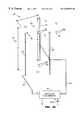
- FIG. 2is perspective view of a preferred embodiment of an ionizing sanitizing device for footwear, according to the present invention
- FIG. 3is an electrical block diagram of the present invention.
- FIG. 4Ais a perspective block diagram showing a first embodiment for an electrode assembly, according to the present invention.
- FIG. 4Bis a plan block diagram of the embodiment of FIG. 4A;
- FIG. 4Cis a perspective block diagram showing a second embodiment for an electrode assembly, according to the present invention.
- FIG. 4Dis a plan block diagram of a modified version of the embodiment of FIG. 4C;
- FIG. 4Eis a perspective block diagram showing a third embodiment for an electrode assembly, according to the present invention.
- FIG. 4Fis a plan block diagram of the embodiment of FIG. 4E;
- FIG. 4Gis a perspective block diagram showing a fourth embodiment for an electrode assembly, according to the present invention.
- FIG. 4His a plan block diagram of the embodiment of FIG. 4G;
- FIG. 4Iis a perspective block diagram showing a fifth embodiment for an electrode assembly, according to the present invention.
- FIG. 4Jis a detailed cross-sectional view of a portion of the embodiment of FIG. 4I;
- FIG. 4Kis a detailed cross-sectional view of a portion of an alternative to the embodiment of FIG. 4I;
- FIG. 5is a partial cutaway perspective view of the present invention showing location of the electrode assemblies, according to the present invention.
- FIG. 2depicts an ionizing footwear sanitizer device 100 according to the present invention as having a common housing or body portion 110 with spaced-apart first and second members 120 A and 120 B projecting therefrom.
- Body portion 100preferably includes one or more air intake vents 130
- the projecting memberspreferably include one or more outlet vents 150 .
- the distal ends of members 120 A and 120 Bpreferably are open, to provide additional outlet venting and to provide user-access for cleaning electrodes in electrode assemblies 220 retained within (as will be described).
- the material comprising the external housing for unit 100is preferably inexpensive, lightweight, and easy to fabricate, ABS plastic for example.
- Device 100preferably is sized such that projecting members 120 A and 120 B can fit within spaced-apart footwear 165 , for example shoes, boots, slippers.
- the total overall length of device 100may be perhaps 7′′ (18 cm) and the spaced-apart distance between members 120 A and 120 B will be a few inches (e.g., 7 cm or so).
- footwear 165could indeed be empty sox, or indeed device 100 may be handheld and used to deodorize a user's bare feet or sock-encased feet.
- an ion generating unit 160Internal to device 100 is an ion generating unit 160 , which comprises various electronic components (described with respect to FIG. 3 ), as well as first and second electrode assemblies 220 A and 220 B, disposed respectively near the distal ends 155 of projecting members 120 A and 120 B.
- Ion generating unit 160receives DC operating power, preferably from four batteries B 1 , B 2 , B 3 , B 4 .
- four D-size cellsare series-coupled to provide 6 VDC, to ion generating unit 160 via an on/off switch S 1 .
- Switch S 1is one of several user-accessible controls 140 mounted on device 100 .
- ion generating unit 160is self-contained in that other than ambient air, nothing is required external to the body device 100 for operation of the present invention.
- a DC power supplycould be disposed external to the housing of device 100 , and power brought into device 100 via a power cable.
- vents 130 , 150may be provided, and the location and/or shapes of these vents can differ from what is depicted in FIG. 2 .
- the role of vents 130 and 150is to ensure that an adequate flow of ambient air may be drawn into (denoted “IN”) or made available to unit 130 , and that an adequate flow of ionized air that includes safe amounts of O 3 flows out (denoted “OUT”) from unit 130 towards the footwear to be sanitized.
- ion generating unit 160includes a high voltage generator unit 170 , preferably electronic circuitry 180 to sense and visually indicate battery potential and a circuit permitting timed energization of the ion generating unit.
- Unit 160also includes a pair of electrode assemblies 220 A and 220 B, that each comprise first and second electrode arrays 230 A- 240 A, and 230 B- 240 B respectively.
- Electrode assemblies 220 A and 220 Bare preferably identical but need not be.
- Array 220 Ais disposed in member 120 A, and array 220 B is disposed in member 120 B. As these arrays are identical, they may interchangeably be referred to as array or arrays 220 .
- first electrode assembly 230 A in assembly 220 Ais preferably identical to first electrode assembly 230 B in assembly 220 B, and these first electrode assemblies may be referred to interchangeably as 220 .
- interchangeable second electrode assemblies 240 A and 240 B(respectively in assemblies 220 A and 220 B) may be referred to interchangeably as 220 .
- first array electrodes 230 and second array electrodes 240creates an electro-kinetic airflow (the “OUT” flow) as well as ozone.
- Circuit 180senses potential on the batteries and indicates whether battery potential is sufficient to generate ions, and when ion generation is occurring.
- a visual indicatoris used, preferably a two-color light emitting diode (“LED”).
- LEDlight emitting diode
- Circuit 180preferably further includes timing components that will turn-off generation of ions and ozone after a predetermined time, for example five minutes. This permits the present invention to be inserted into footwear (e.g., a pair of shoes 165 as indicated in phantom in FIG. 2 ), and energized with switch S 1 , for automatic operation for a user-determined or predetermined time period. During that period, an “OUT” airflow is electro-kinetically created, which airflow carries ozone that can kill or at least diminish odors, germs, and/or bacteria in the footwear.
- high voltage pulse generator unit 170preferably comprises a low voltage oscillator circuit 190 of perhaps 20 KHz frequency, that outputs low voltage pulses to an electronic switch 200 , e.g., a thyristor or the like.
- Switch 200switchably couples the low voltage pulses to the input winding of a step-up transformer T 1 .
- the secondary winding of T 1is coupled to a high voltage multiplier circuit 210 that outputs high voltage pulses.
- the circuitry and components comprising high voltage pulse generator 170 and circuitry 180are fabricated on a printed circuit board that is mounted within housing 110 of unit 100 .
- Output from high voltage generator 170preferably are pulses with at least 10 KV peak-to-peak amplitude, with an effective DC offset of perhaps half the peak-to-peak voltage.
- the pulse trainhas a preferably above-audio frequency of perhaps 20 KHz, and has a duty cycle of perhaps 10%, which will promote battery lifetime. Mechanical vibrations can occur within unit 100 , and an above-audio frequency will prevent any such vibrations from being heard by a user. If desired, different peak-peak amplitudes, DC offsets, pulse train waveshapes, duty cycle, and/or repetition frequencies may instead be used. Indeed, a 100% pulse train (e.g., an essentially DC high voltage) may be used, albeit with shorter battery lifetime.
- first electrode assembly 220 Acomprises first electrode array 230 A and second electrode array 240 A
- second electrode assembly 220 Bcomprises first electrode array 230 B and second electrode array 240 B.
- nomenclature 230will be understood to refer to a first electrode array 230 A and/or 230 B
- nomenclature 240will be understood to refer to a second electrode array 240 A and/or 240 B.
- Unit 170functions as a DC:DC high voltage generator, and could be implemented using other circuitry and/or techniques to output high voltage pulses that are input to electrode assemblies 220 A and 220 B.
- the positive output terminal of unit 170is coupled to the first electrode arrays 230
- the negative output terminalis coupled to the second electrode arrays 240 .
- This coupling polarityhas been found to work well.
- An electrostatic flow of airis created (“OUT”), going from the first electrode array towards the second electrode array.
- the electrode assemblies 220are mounted in the distal end portions 155 of members 120 such that the second electrode arrays 240 are downstream (e.g., closer to the very distal end) from first electrode arrays 230 .
- first and second electrode arrays 230 and 240When voltage or pulses from high voltage pulse generator 170 are coupled across first and second electrode arrays 230 and 240 , it is believed that a plasma-like field is created surrounding electrodes 232 in first array 230 . This electric field ionizes the air between the first and second electrode arrays and establishes an “OUT” airflow that moves towards the second array. It is understood that at least some of the IN flow enters device 100 via vent(s) 130 , and that the OUT flow exits device 100 via vent(s) 150 .
- ozone and ionsare generated simultaneously by the first array electrode(s) 232 , essentially as a function of the potential from generator 170 coupled to the first array. Ozone generation may be increased or decreased by increasing or decreasing the potential at the first array. Coupling an opposite polarity potential to the second array electrode(s) 242 essentially accelerates the motion of ions generated at the first array, producing the air flow denoted as “OUT” in the figures. As the ions move toward the second array, it is believed that they push or move air molecules toward the second array. The relative velocity of this motion may be increased by decreasing the potential at the second array relative to the potential at the first array.
- the exemplary 10 KV potentialcould be divided between the electrode arrays.
- generator 170could provide + 6 KV (or some other fraction) to the first array electrode(s) and ⁇ 4 KV (or some other fraction) to the second array electrode(s).
- +6 KV and the ⁇ 4 KVare measured relative to ground. Understandable it is desired that the present invention operate to output safe amounts of ozone.
- outflow (OUT)preferably includes safe amounts of O 3 that can destroy or at least substantially alter bacteria, germs, and other living (or quasi-living) matter subjected to the outflow.
- pulses from high voltage pulse generator unit 170create an outflow (OUT) of ionized air and O 3 .
- S 1When S 1 is closed, LED will first visually signal whether sufficient Bi potential is present, and if present, then signal when ionization is occurring. If LED fails to indicate sufficient operating voltage, the user will know to replace B 1 or, if rechargeable cells are used, to recharge B 1 .
- the LEDcould signal red when B 1 potential exceeds a minimum threshold, e.g., 5.5 VDC. Further, LED could then signal green when S 1 is depressed and unit 160 is actually outputting ionized air. If the battery potential is too low, the LED will not light, which advises the user to replace or re-charge battery source B 1 .
- a minimum thresholde.g. 5.5 VDC.
- LEDcould then signal green when S 1 is depressed and unit 160 is actually outputting ionized air. If the battery potential is too low, the LED will not light, which advises the user to replace or re-charge battery source B 1 .
- operating parameters of the present inventionare set during manufacture and are not user-adjustable.
- increasing the peak-to-peak output voltage and/or duty cycle in the high voltage pulses generated by unit 170can increase air flowrate, ion content, and ozone content.
- output flowrateis about 90 feet/minute
- ion contentis about 2,000,000/cc
- ozone contentis about 50 ppb (over ambient) to perhaps 2,000 ppb (over ambient).
- Decreasing the R 2 /R 1 ratio below about 20:1will decrease flow rate, as will decreasing the peak-to-peak voltage and/or duty cycle of the high voltage pulses coupled between the first and second electrode arrays.
- a usercan insert device 100 into footwear 165 as shown in FIG. 2 .
- ionization unit 160emits ionized air and preferably some ozone (O 3 ) via outlet vents 150 .
- the interior of the footwearadvantageously is subjected to this outflow (“OUT”) of air and ozone.
- OUToutflow
- the footwear interioris deodorized and the growth of germs, bacteria and the like can be retarded or even eliminated.
- device 100can turn itself off. If desired, device 100 could be used to subject a user's bare feet to the outflow (“OUT”) of ozone-containing ionized air, to deodorize and sanitize the feet.
- each electrode assembly 220will comprise a first array 230 of at least one electrode 232 , and will further comprise a second array 240 of preferably at least one electrode 242 . Understandably material(s) for electrodes 232 and 242 should conduct electricity, be resilient to corrosive effects from the application of high voltage, yet be strong enough to be cleaned.
- the preferred embodiment of device 100will include two electrode assemblies 220 , each of which comprises first and second arrays 230 , 240 , in which each first array includes at least one electrode 232 and in which each second array includes at least one electrode 242 .
- electrode(s) 232 in the first electrode array 230are preferably fabricated from tungsten. Tungsten is sufficiently robust to withstand cleaning, has a high melting point to retard breakdown due to ionization, and has a rough exterior surface that seems to promote efficient ionization.
- electrodes 242preferably will have a highly polished exterior surface to minimize unwanted point-to-point radiation. As such, electrodes 242 preferably are fabricated from stainless steel, brass, among other materials. The polished surface of electrodes 232 also promotes ease of electrode cleaning. User access for electrode cleaning is preferably gained through the open distal portions 155 of members 120 .
- electrodes 232 and 242 according to the present inventionare light weight, easy to fabricate, and lend themselves to mass production. Further, electrodes 232 and 242 described herein promote more efficient generation of ionized air, and production of safe amounts of ozone, O 3 .
- a high voltage pulse generator 170is coupled between the first electrode array 230 and the second electrode array 240 .
- the high voltage pulsesproduce a flow of ionized air that travels in the direction from the first array towards the second array (indicated herein by hollow arrows denoted “OUT”).
- electrode(s) 232may be referred to as an emitting electrode
- electrodes 242may be referred to as collector electrodes.
- This outflowadvantageously contains safe amounts of O 3 , and exits the present invention from vent(s) 150 , as shown in FIG. 2 .
- a generator of high voltage pulsesis preferred and will promote battery life, in practice high voltage DC (e.g., pulses having 100% duty cycle) may instead be used.
- the positive output terminal or port of the high voltage pulse generatorbe coupled to electrodes 232 , and that the negative output terminal or port be coupled to electrodes 242 . It is believed that the net polarity of the emitted ions is positive, e.g., more positive ions than negative ions are emitted. In any event, the preferred electrode assembly electrical coupling minimizes audible hum from electrodes 232 contrasted with reverse polarity (e.g., interchanging the positive and negative output port connections). In some embodiments, however, one port (preferably the negative port) of high voltage pulse generator may in fact be the ambient air. Thus, electrodes in the second array need not be connected to the high voltage pulse generator using wire. Nonetheless, there will be an “effective connection” between the second array electrodes and one output port of the high voltage pulse generator, in this instance, via ambient air.
- an exemplary electrode assembly 220comprises a first array 230 of wire electrodes 232 , and a second array 240 of generally “U”-shaped electrodes 242 .
- the number N 1 of electrodes comprising the first arraywill differ by one relative to the number N 2 of electrodes comprising the second array. In many of the embodiments shown, N 2 >N 1 .
- addition first electrodes 232could be added at the out ends of array 230 such that N 1 >N 2 , e.g., five electrodes 232 compared to four electrodes 242 .
- generator 170is coupled to a pair of electrode assemblies 220 , each of which contains first and second arrays of at least one electrode each. For ease of illustration, only one electrode assembly is shown in the FIGS. 4A-4I.
- Electrodes 232are preferably lengths of tungsten wire, whereas electrodes 242 are formed from sheet metal, preferably stainless steel, although brass or other sheet metal could be used.
- the sheet metalis readily formed to define side regions 244 and bulbous nose region 246 for hollow elongated “U” shaped electrodes 242 . While FIG. 4A depicts four electrodes 242 in second array 240 and three electrodes 232 in first array 230 , as noted, other numbers of electrodes in each array could be used, preferably retaining a symmetrically staggered configuration as shown.
- the spaced-apart configuration between the arraysis staggered such that each first array electrode 232 is substantially equidistant from two second array electrodes 242 .
- This symmetrical staggeringhas been found to be an especially efficient electrode placement.
- the staggering geometryis symmetrical in that adjacent electrodes 232 or adjacent electrodes 242 are spaced-apart a constant distance, Y 1 and Y 2 respectively.
- a non-symmetrical configurationcould also be used, although ion emission and air flow would likely be diminished.
- the number of electrodes 232 and 242may differ from what is shown.
- electrodes 232typically dimensions are as follows: diameter of electrodes 232 is about 0.08 mm, distances Y 1 and Y 2 are each about 16 mm, distance X 1 is about 16 mm, distance L is about 20 mm, and electrode heights Z 1 and Z 2 are each about 100 mm.
- the width W of electrodes 242is preferably about 4 mm, and the thickness of the material from which electrodes 242 are formed is about 0.5 mm. Of course other dimensions and shapes could be used. It is preferred that electrodes 232 be small in diameter to help establish a desired high voltage field. On the other hand, it is desired that electrodes 232 (as well as electrodes 242 ) be sufficiently robust to withstand occasional cleaning.
- Electrodes 232 in first array 230are coupled by a conductor 234 to a first (preferably positive) output port of high voltage pulse generator 170
- electrodes 242 in second array 240are coupled by a conductor 244 to a second (preferably negative) output port of generator 170 .
- FIG. 4Bdepicts conductor 244 making connection with some electrodes 242 internal to bulbous end 246 , while other electrodes 242 make electrical connection to conductor 244 elsewhere on the electrode. Electrical connection to the various electrodes 242 could also be made on the electrode external surface providing no substantial impairment of the outflow airstream results.
- the ratio of the effective electric field emanating area of electrode 232 to the nearest effective area of electrodes 242is at least about 15:1, and preferably is at least 20:1. Beyond a ratio of say 35:1, little or no performance improvement results.
- ionizationappears to occur at the smaller electrode(s) 232 in the first electrode array 230 , with ozone production occurring as a function of high voltage arcing.
- increasing the peak-to-peak voltage amplitude and/or duty cycle of the pulses from the high voltage pulse generator 170can increase ozone content in the output flow of ionized air.
- each “U”-shaped electrode 242has two trailing edges 244 that promote efficient kinetic transport of the outflow of ionized air and O 3 .
- the embodiments of FIGS. 4C and 4Ddepict somewhat truncated versions of electrodes 242 .
- dimension L in the embodiment of FIGS. 4A and 4Bwas about 20 mm
- FIGS. 4C and 4DL has been shortened to about 8 mm.
- Other dimensions in FIG. 4Cpreferably are similar to those stated for FIGS. 4A and 4B.
- the inclusion of point-like regions 246 on the trailing edge of electrodes 242seems to promote more efficient generation of ionized air flow.
- second electrode array 240 in FIG. 4Ccan be more robust than the configuration of FIGS. 4A and 4B, by virtue of the shorter trailing edge geometry. As noted earlier, a symmetrical staggered geometry for the first and second electrode arrays is preferred for the configuration of FIG. 4 C.
- the outermost second electrodesdenoted 242 - 1 and 242 - 2 , have substantially no outermost trailing edges.
- Dimension L in FIG. 4Dis preferably about 3 mm, and other dimensions may be as stated for the configuration of FIGS. 4A and 4B. Again, the R 2 /R 1 ratio for the embodiment of FIG. 4D preferably exceeds about 20:1.
- FIGS. 4E and 4Fdepict another embodiment of electrode assembly 220 , in which the first electrode array comprises a single wire electrode 232 , and the second electrode array comprises a single pair of curved “L”-shaped electrodes 242 , in cross-section.
- Typical dimensionswhere different than what has been stated for earlier-described embodiments, are X 1 ⁇ 12 mm, Y 1 ⁇ 6 mm, Y 2 ⁇ 3 mm, and L 1 ⁇ 3 mm.
- the effective R 2 /R 1 ratiois again greater than about 20:1.
- the fewer electrodes comprising assembly 220 in FIGS. 4E and 4Fpromote economy of construction, and ease of cleaning, although more than one electrode 232 , and more than two electrodes 242 could of course be employed.
- This embodimentagain incorporates the staggered symmetry described earlier, in which electrode 232 is equidistant from two electrodes 242 .
- FIGS. 4G and 4Hshown yet another embodiment for electrode assembly 220 .
- first electrode array 230is a length of wire 232
- the second electrode array 240comprises a pair of rod or columnar electrodes 242 .
- electrode 232be symmetrically equidistant from electrodes 242 .
- Wire electrode 232is preferably perhaps 0.08 mm tungsten
- columnar electrodes 242are perhaps 2 mm diameter stainless steel.
- the R 2 /R 1 ratiois about 25:1.
- Other dimensionsmay be similar to other configurations, e.g., FIG. 4E, 4 F.
- electrode assembly 220may comprise more than one electrode 232 , and more than two electrodes 242 .
- the first electrode assemblycomprises a single pin-like element 232 disposed coaxially with a second electrode array that comprises a single ring-like electrode 242 having a rounded inner opening 246 .
- electrode assembly 220may comprise a plurality of such pin-like and ring-like elements.
- electrode 232is tungsten
- electrode 242is stainless steel.
- Typical dimensions for the embodiment of FIG. 4 I and FIG. 4Jare L 1 ⁇ 10 mm, X 1 ⁇ 9.5 mm, T ⁇ 0.5 mm, and the diameter of opening 246 is about 12 mm.
- Dimension L 1preferably is sufficiently long that upstream portions of electrode 232 (e.g., portions to the left in FIG. 4I) do not interfere with the electrical field between electrode 232 and the collector electrode 242 .
- the effect R 2 /R 1 ratiois governed by the tip geometry of electrode 232 . Again, in the preferred embodiment, this ratio exceeds about 20:1. Lines drawn in phantom in FIG.
- 4Jdepict theoretical electric force field lines, emanating from emitter electrode 232 , and terminating on the curved surface of collector electrode 246 .
- the bulk of the fieldemanates within about +45° of coaxial axis between electrode 232 and electrode 242 .
- the opening in electrode 242 and/or electrode 232 and 242 geometryis such that too narrow an angle about the coaxial axis exists, air flow will be unduly restricted.
- One advantage of the ring-pin electrode assembly configuration shown in FIG. 4Iis that the flat regions of ring-like electrode 242 provide sufficient surface area to which dust entrained in the moving air stream can attach, yet be readily cleaned.
- the air stream (OUT) emitted by device 100has reduced dust content, especially contrasted to prior art kinetic air mover configurations.
- dust or dirt particles within the footwearmay be removed.
- the ring-pin configurationadvantageously generates more ozone than prior art configurations, or the configurations of FIGS. 4A-4H.
- the configurations of FIGS. 4A-4Hmay generate perhaps 50 ppb ozone
- the configuration of FIG. 4Ican generate about 2,000 ppb ozone, without an increase in demand upon power supply B 1 .
- first array pin electrodesmay be utilized with the second array electrodes of FIGS. 4A-4H.
- second array ring electrodesmay be utilized with the first array electrodes of FIGS. 4A-4H.
- each wire or columnar electrode 232is replaced by a column of electrically series-connected pin electrodes (e.g., as shown in FIGS. 4 I- 4 K), while retaining the second electrode arrays as depicted in these figures.
- the first array electrodescan remain as depicted, but each of the second array electrodes 242 is replaced by a column of electrically series-connected ring electrodes (e.g., as shown in FIGS. 4 I- 4 K).
- FIG. 4Ja detailed cross-sectional view of the central portion of electrode 242 in FIG. 4I is shown.
- curved region 246 adjacent the central opening in electrode 242appears to provide an acceptably large surface area to which many ionization paths from the distal tip of electrode 232 have substantially equal path length.
- the adjacent regions of electrode 242preferably provide many equidistant inter-electrode array paths.
- a high exit flowrate of perhaps 90 feet/minute and 2,000 ppb range ozone emission attainable with this configurationconfirm a high operating efficiency.
- one or more electrodes 232is replaced by a conductive block 232 ′′ of carbon fibers, the block having a distal surface in which projecting fibers 233 - 1 , . . . 233 -N take on the appearance of a “bed of nails”.
- the projecting fiberscan each act as-an emitting electrode and provide a plurality of emitting surfaces. Over a period of time, some or all of the electrodes will literally be consumed, whereupon graphite block 232 ′′ will be replaced. Materials other than graphite may be used for block 232 ′′ providing the material has a surface with projecting conductive fibers such as 233 -N.
- FIG. 5shows member 120 A partially cutaway to depict the location of a typical electrode assembly 220 A.
- electrode assembly 220 Aincludes first and second arrays 230 A and 240 A, whose electrodes are similar to that depicted in FIG. 4 I.
- FIG. 5depicts electrode assemblies 220 with the ring-pin configuration of FIG. 4I, it is understood that any of the alternative configurations of FIGS. 4A-4G could instead be contained within members 120 A, 120 B. Indeed, there is no requirement that the present invention provide two projecting members 120 A and 120 B. If desired, the present invention could be implemented with a single projecting member, e.g., member 120 A, although providing more than one member reduces the time necessary to sanitize a pair of footwear. By the same token, the present invention could be implemented with more than two pairs of projecting members, e.g., perhaps four pairs, to permit sanitizing more than one pair of footwear simultaneously.
- the inner distal portions of members 120include an electrostatic shield that reduces detectable electromagnetic radiation external to device 100 .
- a metal shieldcould be disposed within members 120 , or portions of the interior of members 120 could be coated with a metallic paint to reduce such radiation.
- the net output of ionscould be influenced by placing a bias element near some or all of the output vents.
- a bias elementcould be electrically biased to neutralize negative ions, thereby increasing the net output of positive ions.
- the present inventioncould be adjusted to produce ions without producing ozone, if desired.
Landscapes
- Health & Medical Sciences (AREA)
- Epidemiology (AREA)
- Life Sciences & Earth Sciences (AREA)
- Animal Behavior & Ethology (AREA)
- General Health & Medical Sciences (AREA)
- Public Health (AREA)
- Veterinary Medicine (AREA)
- Footwear And Its Accessory, Manufacturing Method And Apparatuses (AREA)
Abstract
Description
This invention relates to devices that sanitize footwear and more particularly to methods and devices for electro-kinetically producing a flow of ionized air containing safe amounts of ozone (O3) into such footwear.
Shoes, boots, socks, and other footwear can too readily take on an unpleasant odor from the wearer's feet. Indeed, the moist and warm environment within footwear can promote the undesired and unhealthy growth of bacteria or germs. (As used herein, the term footwear will be understood to include shoes, boots, slippers, socks, and the like.)
It is known in the art to attempt to deodorize footwear passively, for example by allowing shoes or the like to air out when not being worn. It is also known to insert a chemical into an empty shoe or boot, naphtha perhaps, to impart an odor that will perhaps dominate the odor from the user's feet.
However such passive techniques are time consuming and do little or nothing to truly sanitize the footwear. Sanitization can be especially troublesome with children's shoes because children during play often interchange shoes.
One can attempt to actively produce an air flow in an empty shoe with a small fan, to help deodorize the shoe. However the relatively bulky fan or blade mechanism often blocks air attempting to flow out of the footwear. Further, simply flowing air into a shoe does little to remove the cause of the odor in the shoe, bacteria or germs that can exist on the insole or inner lining of the shoe.
Techniques are known to actively produce an air flow using electro-kinetic techniques, by which electrical power is directly converted into a flow of air without mechanically moving components. One such system is described in U.S. Pat. No. 4,789,801 to Lee (1988), depicted herein in simplified form as FIGS. 1A and 1B. Lee'ssystem 10 provides a first array of small area (“minisectional”)electrodes 20 is spaced-apart symmetrically from a second array of larger area (“maxisectional”)electrodes 30, with a high voltage (e.g., 5 KV)pulse generator 40 coupled between the two arrays.Generator 40 outputs high voltage pulses that ionize the air between the arrays, producing anair flow 50 from the minisectional array toward the maxisectional array results. The high voltage field present between the two arrays can release ozone (O3), which can advantageously safely destroy many types of bacteria if excessive quantities of ozone are not released.
Unfortunately, Lee's tear-shaped maxisectional electrodes are relatively expensive to fabricate, most likely requiring mold-casting or extrusion processes. Further, air flow and ion generation efficiency is not especially high using Lee's configuration. A Lee-type electrode configuration would be difficult to mass produce economically for use in a device intended to sanitize footwear.
There is a need for a footwear sanitizer that can not produce an air flow within an empty shoe or boot, but can also provide true sanitizing action. Preferably such a device should subject the interior of the footwear to a flow of ions containing ozone, to promote sanitation, in addition to deodorizing the footwear.
The present invention provides such a sanitizing device.
The present invention provides a footwear sanitizer device whose housing includes a central portion and two projecting members that are spaced-apart a distance to permit inserting each member into a shoe (or the like). The projecting members are sized to slide into the length of the shoe.
An electrode assembly is located within the distal portion of each projecting member, each assembly comprising a first and second array of electrodes. A battery-operated ionizer unit with DC battery power supply is contained within the housing. The ionizer unit includes a DC:DC inverter that boosts the battery voltage to high voltage, and a generator that receives the high voltage DC and outputs high voltage, pulses or DC, of perhaps 10 KV peak-to-peak. The high voltage output from the high voltage generator is coupled between the first and second array of electrodes in each electrode assembly. Preferably each first and second array is coupled respectively to the positive and negative output ports of the high voltage generator.
Each electrode assembly preferably is formed using first and second arrays of readily manufacturable electrode types. In one embodiment, the first array comprises wire-like electrodes and the second array comprises “U”-shaped electrodes having one or two trailing surfaces. In an even more efficient embodiment, the first array includes at least one pin or cone-like electrode and the second array is an annular washer-like electrode. The electrode assembly may comprise various combinations of the described first and second array electrodes. In the various embodiments, the ratio between effective area of the second array electrodes to the first array electrodes is at least about 20:1.
The high voltage creates an electric field between the first and second electrode arrays to produce an electro-kinetic airflow from the first array toward the second array, the airflow being rich in ions and in ozone (O3). Ambient air enters the device through at least one air intake vent, and ionized air (with ozone) exits the distal region of the projecting members through at least one outlet vent. If desired, a single vent in each projecting member can suffice as both an intake and an outlet vent. Preferably a visual indicator is coupled to the ionizer unit to visually confirm to a user when the unit is ready for ionizing operation, and when ionization is actually occurring.
The projecting members are inserted into footwear and the device is turned on, energizing the ion generator. The interior of the footwear is subjected to an outflow of ionized air containing ozone. The resultant airflow not only electro-kinetically airs out the interior of the footwear, but the ozone-rich ionized air flow sanitizes and deodorizes the interior as well.
Other features and advantages of the invention will appear from the following description in which the preferred embodiments have been set forth in detail, in conjunction with the accompanying drawings.
FIGS. 1A and 1B are depictions of Lee-type electrostatic generators, according to the prior art;
FIG. 2 is perspective view of a preferred embodiment of an ionizing sanitizing device for footwear, according to the present invention;
FIG. 3 is an electrical block diagram of the present invention;
FIG. 4A is a perspective block diagram showing a first embodiment for an electrode assembly, according to the present invention;
FIG. 4B is a plan block diagram of the embodiment of FIG. 4A;
FIG. 4C is a perspective block diagram showing a second embodiment for an electrode assembly, according to the present invention;
FIG. 4D is a plan block diagram of a modified version of the embodiment of FIG. 4C;
FIG. 4E is a perspective block diagram showing a third embodiment for an electrode assembly, according to the present invention;
FIG. 4F is a plan block diagram of the embodiment of FIG. 4E;
FIG. 4G is a perspective block diagram showing a fourth embodiment for an electrode assembly, according to the present invention;
FIG. 4H is a plan block diagram of the embodiment of FIG. 4G;
FIG. 4I is a perspective block diagram showing a fifth embodiment for an electrode assembly, according to the present invention;
FIG. 4J is a detailed cross-sectional view of a portion of the embodiment of FIG. 4I;
FIG. 4K is a detailed cross-sectional view of a portion of an alternative to the embodiment of FIG. 4I;
FIG. 5 is a partial cutaway perspective view of the present invention showing location of the electrode assemblies, according to the present invention.
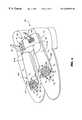
FIG. 2 depicts an ionizingfootwear sanitizer device 100 according to the present invention as having a common housing orbody portion 110 with spaced-apart first andsecond members Body portion 100 preferably includes one or more air intake vents130, and the projecting members preferably include one or more outlet vents150. In addition, the distal ends ofmembers electrode assemblies 220 retained within (as will be described).
The material comprising the external housing forunit 100 is preferably inexpensive, lightweight, and easy to fabricate, ABS plastic for example.Device 100 preferably is sized such that projectingmembers footwear 165, for example shoes, boots, slippers. Thus the total overall length ofdevice 100 may be perhaps 7″ (18 cm) and the spaced-apart distance betweenmembers footwear 165 could indeed be empty sox, or indeeddevice 100 may be handheld and used to deodorize a user's bare feet or sock-encased feet.
Internal todevice 100 is anion generating unit 160, which comprises various electronic components (described with respect to FIG.3), as well as first andsecond electrode assemblies members Ion generating unit 160 receives DC operating power, preferably from four batteries B1, B2, B3, B4. In a preferred embodiment, four D-size cells are series-coupled to provide 6 VDC, toion generating unit 160 via an on/off switch S1. Switch S1 is one of several user-accessible controls 140 mounted ondevice 100. As such,ion generating unit 160 is self-contained in that other than ambient air, nothing is required external to thebody device 100 for operation of the present invention. Of course if desired, a DC power supply could be disposed external to the housing ofdevice 100, and power brought intodevice 100 via a power cable.
It is understood that the shape or configuration shown in FIG. 2 is only exemplary, and other dimensions and configurations may be used. More orfewer vents vents unit 130, and that an adequate flow of ionized air that includes safe amounts of O3flows out (denoted “OUT”) fromunit 130 towards the footwear to be sanitized.
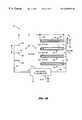
As best seen in FIG. 3,ion generating unit 160 includes a highvoltage generator unit 170, preferablyelectronic circuitry 180 to sense and visually indicate battery potential and a circuit permitting timed energization of the ion generating unit.Unit 160 also includes a pair ofelectrode assemblies second electrode arrays 230A-240A, and230B-240B respectively.Electrode assemblies Array 220A is disposed inmember 120A, andarray 220B is disposed inmember 120B. As these arrays are identical, they may interchangeably be referred to as array orarrays 220. Similarlyfirst electrode assembly 230A inassembly 220A is preferably identical tofirst electrode assembly 230B inassembly 220B, and these first electrode assemblies may be referred to interchangeably as220. Similarly, interchangeablesecond electrode assemblies assemblies
As will be described, the application of high voltage betweenfirst array electrodes 230 andsecond array electrodes 240 creates an electro-kinetic airflow (the “OUT” flow) as well as ozone.
As shown in FIG. 3, high voltagepulse generator unit 170 preferably comprises a lowvoltage oscillator circuit 190 of perhaps20 KHz frequency, that outputs low voltage pulses to anelectronic switch 200, e.g., a thyristor or the like. Switch200 switchably couples the low voltage pulses to the input winding of a step-up transformer T1. The secondary winding of T1 is coupled to a highvoltage multiplier circuit 210 that outputs high voltage pulses. Preferably the circuitry and components comprising highvoltage pulse generator 170 andcircuitry 180 are fabricated on a printed circuit board that is mounted withinhousing 110 ofunit 100.
Output fromhigh voltage generator 170 preferably are pulses with at least 10 KV peak-to-peak amplitude, with an effective DC offset of perhaps half the peak-to-peak voltage. The pulse train has a preferably above-audio frequency of perhaps 20 KHz, and has a duty cycle of perhaps 10%, which will promote battery lifetime. Mechanical vibrations can occur withinunit 100, and an above-audio frequency will prevent any such vibrations from being heard by a user. If desired, different peak-peak amplitudes, DC offsets, pulse train waveshapes, duty cycle, and/or repetition frequencies may instead be used. Indeed, a 100% pulse train (e.g., an essentially DC high voltage) may be used, albeit with shorter battery lifetime.
The output from high voltagepulse generator unit 170 is coupled toelectrode assemblies first electrode assembly 220A comprisesfirst electrode array 230A andsecond electrode array 240A, whilesecond electrode assembly 220B comprisesfirst electrode array 230B andsecond electrode array 240B. For ease of reference,nomenclature 230 will be understood to refer to afirst electrode array 230A and/or230B, andnomenclature 240 will be understood to refer to asecond electrode array 240A and/or240B.
In the embodiment of FIG. 3, the positive output terminal ofunit 170 is coupled to thefirst electrode arrays 230, and the negative output terminal is coupled to thesecond electrode arrays 240. This coupling polarity has been found to work well. An electrostatic flow of air is created (“OUT”), going from the first electrode array towards the second electrode array. Accordingly theelectrode assemblies 220 are mounted in thedistal end portions 155 of members120 such that thesecond electrode arrays 240 are downstream (e.g., closer to the very distal end) fromfirst electrode arrays 230.
When voltage or pulses from highvoltage pulse generator 170 are coupled across first andsecond electrode arrays electrodes 232 infirst array 230. This electric field ionizes the air between the first and second electrode arrays and establishes an “OUT” airflow that moves towards the second array. It is understood that at least some of the IN flow entersdevice 100 via vent(s)130, and that the OUT flow exitsdevice 100 via vent(s)150.
It is believed that ozone and ions are generated simultaneously by the first array electrode(s)232, essentially as a function of the potential fromgenerator 170 coupled to the first array. Ozone generation may be increased or decreased by increasing or decreasing the potential at the first array. Coupling an opposite polarity potential to the second array electrode(s)242 essentially accelerates the motion of ions generated at the first array, producing the air flow denoted as “OUT” in the figures. As the ions move toward the second array, it is believed that they push or move air molecules toward the second array. The relative velocity of this motion may be increased by decreasing the potential at the second array relative to the potential at the first array.
For example, if +10 KV were applied to the first array electrode(s), and no potential were applied to the second array electrode(s), a cloud of ions (whose net charge is positive) would form adjacent the first electrode array. Further, the relatively high 10 KV potential would generate substantial ozone. By coupling a relatively negative potential to the second array electrode(s), the velocity of the air mass moved by the net emitted ions increases, as momentum of the moving ions is conserved.
On the other hand, if it were desired to maintain the same effective outflow (OUT) velocity but to generate less ozone, the exemplary 10 KV potential could be divided between the electrode arrays. For example,generator 170 could provide +6 KV (or some other fraction) to the first array electrode(s) and −4 KV (or some other fraction) to the second array electrode(s). In this example, it is understood that the +6 KV and the −4 KV are measured relative to ground. Understandable it is desired that the present invention operate to output safe amounts of ozone.
As noted, outflow (OUT) preferably includes safe amounts of O3that can destroy or at least substantially alter bacteria, germs, and other living (or quasi-living) matter subjected to the outflow. Thus, when switch S1 is closed and B1 has sufficient operating potential, pulses from high voltagepulse generator unit 170 create an outflow (OUT) of ionized air and O3. When S1 is closed, LED will first visually signal whether sufficient Bi potential is present, and if present, then signal when ionization is occurring. If LED fails to indicate sufficient operating voltage, the user will know to replace B1 or, if rechargeable cells are used, to recharge B1. For example, if visual indicator is a two-color device, the LED could signal red when B1 potential exceeds a minimum threshold, e.g., 5.5 VDC. Further, LED could then signal green when S1 is depressed andunit 160 is actually outputting ionized air. If the battery potential is too low, the LED will not light, which advises the user to replace or re-charge battery source B1.
Preferably operating parameters of the present invention are set during manufacture and are not user-adjustable. For example, increasing the peak-to-peak output voltage and/or duty cycle in the high voltage pulses generated byunit 170 can increase air flowrate, ion content, and ozone content. In the preferred embodiment, output flowrate is about 90 feet/minute, ion content is about 2,000,000/cc and ozone content is about 50 ppb (over ambient) to perhaps 2,000 ppb (over ambient). Decreasing the R2/R1 ratio below about 20:1 will decrease flow rate, as will decreasing the peak-to-peak voltage and/or duty cycle of the high voltage pulses coupled between the first and second electrode arrays.
In practice, a user can insertdevice 100 intofootwear 165 as shown in FIG.2. With S1 energized,ionization unit 160 emits ionized air and preferably some ozone (O3) via outlet vents150. The interior of the footwear advantageously is subjected to this outflow (“OUT”) of air and ozone. Beneficially, the footwear interior is deodorized and the growth of germs, bacteria and the like can be retarded or even eliminated. After a predetermined time period,device 100 can turn itself off. If desired,device 100 could be used to subject a user's bare feet to the outflow (“OUT”) of ozone-containing ionized air, to deodorize and sanitize the feet.
Having described various aspects of the invention in general, preferred embodiments ofelectrode assemblies 220 will now be described. In the various embodiments, eachelectrode assembly 220 will comprise afirst array 230 of at least oneelectrode 232, and will further comprise asecond array 240 of preferably at least oneelectrode 242. Understandably material(s) forelectrodes device 100 will include twoelectrode assemblies 220, each of which comprises first andsecond arrays electrode 232 and in which each second array includes at least oneelectrode 242.
In the various electrode assemblies to be described herein, electrode(s)232 in thefirst electrode array 230 are preferably fabricated from tungsten. Tungsten is sufficiently robust to withstand cleaning, has a high melting point to retard breakdown due to ionization, and has a rough exterior surface that seems to promote efficient ionization. On the other hand,electrodes 242 preferably will have a highly polished exterior surface to minimize unwanted point-to-point radiation. As such,electrodes 242 preferably are fabricated from stainless steel, brass, among other materials. The polished surface ofelectrodes 232 also promotes ease of electrode cleaning. User access for electrode cleaning is preferably gained through the opendistal portions 155 of members120.
In contrast to the prior art electrodes disclosed by Lee,electrodes electrodes
In the present invention, a highvoltage pulse generator 170 is coupled between thefirst electrode array 230 and thesecond electrode array 240. The high voltage pulses produce a flow of ionized air that travels in the direction from the first array towards the second array (indicated herein by hollow arrows denoted “OUT”). As such, electrode(s)232 may be referred to as an emitting electrode, andelectrodes 242 may be referred to as collector electrodes. This outflow advantageously contains safe amounts of O3, and exits the present invention from vent(s)150, as shown in FIG.2. Although a generator of high voltage pulses is preferred and will promote battery life, in practice high voltage DC (e.g., pulses having 100% duty cycle) may instead be used.
According to the present invention, it is preferred that the positive output terminal or port of the high voltage pulse generator be coupled toelectrodes 232, and that the negative output terminal or port be coupled toelectrodes 242. It is believed that the net polarity of the emitted ions is positive, e.g., more positive ions than negative ions are emitted. In any event, the preferred electrode assembly electrical coupling minimizes audible hum fromelectrodes 232 contrasted with reverse polarity (e.g., interchanging the positive and negative output port connections). In some embodiments, however, one port (preferably the negative port) of high voltage pulse generator may in fact be the ambient air. Thus, electrodes in the second array need not be connected to the high voltage pulse generator using wire. Nonetheless, there will be an “effective connection” between the second array electrodes and one output port of the high voltage pulse generator, in this instance, via ambient air.
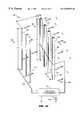
Turning now to the embodiments of FIGS. 4A and 4B, anexemplary electrode assembly 220 comprises afirst array 230 ofwire electrodes 232, and asecond array 240 of generally “U”-shapedelectrodes 242. In preferred embodiments, the number N1 of electrodes comprising the first array will differ by one relative to the number N2 of electrodes comprising the second array. In many of the embodiments shown, N2>N1. However, if desired, in FIG. 4A, additionfirst electrodes 232 could be added at the out ends ofarray 230 such that N1>N2, e.g., fiveelectrodes 232 compared to fourelectrodes 242. Again it is to be understood thatgenerator 170 is coupled to a pair ofelectrode assemblies 220, each of which contains first and second arrays of at least one electrode each. For ease of illustration, only one electrode assembly is shown in the FIGS. 4A-4I.
As best seen in FIG. 4B, the spaced-apart configuration between the arrays is staggered such that eachfirst array electrode 232 is substantially equidistant from twosecond array electrodes 242. This symmetrical staggering has been found to be an especially efficient electrode placement. Preferably the staggering geometry is symmetrical in thatadjacent electrodes 232 oradjacent electrodes 242 are spaced-apart a constant distance, Y1 and Y2 respectively. However, a non-symmetrical configuration could also be used, although ion emission and air flow would likely be diminished. Also, it is understood that the number ofelectrodes
In FIG. 4A, typically dimensions are as follows: diameter ofelectrodes 232 is about 0.08 mm, distances Y1 and Y2 are each about 16 mm, distance X1 is about 16 mm, distance L is about 20 mm, and electrode heights Z1 and Z2 are each about 100 mm. The width W ofelectrodes 242 is preferably about 4 mm, and the thickness of the material from whichelectrodes 242 are formed is about 0.5 mm. Of course other dimensions and shapes could be used. It is preferred thatelectrodes 232 be small in diameter to help establish a desired high voltage field. On the other hand, it is desired that electrodes232 (as well as electrodes242) be sufficiently robust to withstand occasional cleaning.
The ratio of the effective electric field emanating area ofelectrode 232 to the nearest effective area ofelectrodes 242 is at least about 15:1, and preferably is at least 20:1. Beyond a ratio of say 35:1, little or no performance improvement results. Thus, in the embodiment of FIG.4A and FIG. 4B, the ratio R2/R1≈2 mm/ 0.08 mm≈25:1.
In this and the other embodiments to be described herein, ionization appears to occur at the smaller electrode(s)232 in thefirst electrode array 230, with ozone production occurring as a function of high voltage arcing. For example, increasing the peak-to-peak voltage amplitude and/or duty cycle of the pulses from the highvoltage pulse generator 170 can increase ozone content in the output flow of ionized air.
In the embodiment of FIGS. 4A and 4C, each “U”-shapedelectrode 242 has two trailingedges 244 that promote efficient kinetic transport of the outflow of ionized air and O3. By contrast, the embodiments of FIGS. 4C and 4D depict somewhat truncated versions ofelectrodes 242. Whereas dimension L in the embodiment of FIGS. 4A and 4B was about 20 mm, in FIGS. 4C and 4D, L has been shortened to about 8 mm. Other dimensions in FIG. 4C preferably are similar to those stated for FIGS. 4A and 4B. In FIGS. 4C and 4D, the inclusion of point-like regions 246 on the trailing edge ofelectrodes 242 seems to promote more efficient generation of ionized air flow. It will be appreciated that the configuration ofsecond electrode array 240 in FIG. 4C can be more robust than the configuration of FIGS. 4A and 4B, by virtue of the shorter trailing edge geometry. As noted earlier, a symmetrical staggered geometry for the first and second electrode arrays is preferred for the configuration of FIG.4C.
In the embodiment of FIG. 4D, the outermost second electrodes, denoted242-1 and242-2, have substantially no outermost trailing edges. Dimension L in FIG. 4D is preferably about 3 mm, and other dimensions may be as stated for the configuration of FIGS. 4A and 4B. Again, the R2/R1 ratio for the embodiment of FIG. 4D preferably exceeds about 20:1.
FIGS. 4E and 4F depict another embodiment ofelectrode assembly 220, in which the first electrode array comprises asingle wire electrode 232, and the second electrode array comprises a single pair of curved “L”-shapedelectrodes 242, in cross-section. Typical dimensions, where different than what has been stated for earlier-described embodiments, are X1≈12 mm, Y1≈6 mm, Y2≈3 mm, and L1≈3 mm. The effective R2/R1 ratio is again greater than about 20:1. The fewerelectrodes comprising assembly 220 in FIGS. 4E and 4F promote economy of construction, and ease of cleaning, although more than oneelectrode 232, and more than twoelectrodes 242 could of course be employed. This embodiment again incorporates the staggered symmetry described earlier, in which electrode232 is equidistant from twoelectrodes 242.
FIGS. 4G and 4H shown yet another embodiment forelectrode assembly 220. In this embodiment,first electrode array 230 is a length ofwire 232, while thesecond electrode array 240 comprises a pair of rod orcolumnar electrodes 242. As in embodiments described earlier herein, it is preferred thatelectrode 232 be symmetrically equidistant fromelectrodes 242.Wire electrode 232 is preferably perhaps 0.08 mm tungsten, whereascolumnar electrodes 242 are perhaps 2 mm diameter stainless steel. Thus, in this embodiment the R2/R1 ratio is about 25:1. Other dimensions may be similar to other configurations, e.g., FIG. 4E,4F. Of courseelectrode assembly 220 may comprise more than oneelectrode 232, and more than twoelectrodes 242.
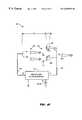
An especially preferred embodiment is shown in FIG.4I and FIG.4J. In these figures, the first electrode assembly comprises a single pin-like element 232 disposed coaxially with a second electrode array that comprises a single ring-like electrode 242 having a roundedinner opening 246. However, as indicated byphantom elements 232′,242′,electrode assembly 220 may comprise a plurality of such pin-like and ring-like elements. Preferablyelectrode 232 is tungsten, andelectrode 242 is stainless steel.
Typical dimensions for the embodiment of FIG.4I and FIG. 4J are L1≈10 mm, X1≈9.5 mm, T≈0.5 mm, and the diameter ofopening 246 is about 12 mm. Dimension L1 preferably is sufficiently long that upstream portions of electrode232 (e.g., portions to the left in FIG. 4I) do not interfere with the electrical field betweenelectrode 232 and thecollector electrode 242. However, as shown in FIG. 4J, the effect R2/R1 ratio is governed by the tip geometry ofelectrode 232. Again, in the preferred embodiment, this ratio exceeds about 20:1. Lines drawn in phantom in FIG. 4J depict theoretical electric force field lines, emanating fromemitter electrode 232, and terminating on the curved surface ofcollector electrode 246. Preferably the bulk of the field emanates within about +45° of coaxial axis betweenelectrode 232 andelectrode 242. On the other hand, if the opening inelectrode 242 and/orelectrode like electrode 242 provide sufficient surface area to which dust entrained in the moving air stream can attach, yet be readily cleaned. As a result, the air stream (OUT) emitted bydevice 100 has reduced dust content, especially contrasted to prior art kinetic air mover configurations. Thus, in addition to being sanitized and deodorized, dust or dirt particles within the footwear may be removed.
Further, the ring-pin configuration advantageously generates more ozone than prior art configurations, or the configurations of FIGS. 4A-4H. For example, whereas the configurations of FIGS. 4A-4H may generate perhaps 50 ppb ozone, the configuration of FIG. 4I can generate about 2,000 ppb ozone, without an increase in demand upon power supply B1.
Nonetheless it will be appreciated that applicants' first array pin electrodes may be utilized with the second array electrodes of FIGS. 4A-4H. Further, applicants' second array ring electrodes may be utilized with the first array electrodes of FIGS. 4A-4H. For example, in modifications of the embodiments of FIGS. 4A-4H, each wire orcolumnar electrode 232 is replaced by a column of electrically series-connected pin electrodes (e.g., as shown in FIGS.4I-4K), while retaining the second electrode arrays as depicted in these figures. By the same token, in other modifications of the embodiments of FIGS. 4A-4H, the first array electrodes can remain as depicted, but each of thesecond array electrodes 242 is replaced by a column of electrically series-connected ring electrodes (e.g., as shown in FIGS.4I-4K).
In FIG. 4J, a detailed cross-sectional view of the central portion ofelectrode 242 in FIG. 4I is shown. As best seen in FIG. 4J,curved region 246 adjacent the central opening inelectrode 242 appears to provide an acceptably large surface area to which many ionization paths from the distal tip ofelectrode 232 have substantially equal path length. Thus, while the distal tip (or emitting tip) ofelectrode 232 is advantageously small to concentrate the electric field between the electrode arrays, the adjacent regions ofelectrode 242 preferably provide many equidistant inter-electrode array paths. A high exit flowrate of perhaps 90 feet/minute and 2,000 ppb range ozone emission attainable with this configuration confirm a high operating efficiency.
In FIG. 4K, one ormore electrodes 232 is replaced by aconductive block 232″ of carbon fibers, the block having a distal surface in which projecting fibers233-1, . . .233-N take on the appearance of a “bed of nails”. The projecting fibers can each act as-an emitting electrode and provide a plurality of emitting surfaces. Over a period of time, some or all of the electrodes will literally be consumed, whereupongraphite block 232″ will be replaced. Materials other than graphite may be used forblock 232″ providing the material has a surface with projecting conductive fibers such as233-N.
FIG. 5 showsmember 120A partially cutaway to depict the location of atypical electrode assembly 220A. In FIG. 5,electrode assembly 220A includes first andsecond arrays electrode assemblies 220 with the ring-pin configuration of FIG. 4I, it is understood that any of the alternative configurations of FIGS. 4A-4G could instead be contained withinmembers members member 120A, although providing more than one member reduces the time necessary to sanitize a pair of footwear. By the same token, the present invention could be implemented with more than two pairs of projecting members, e.g., perhaps four pairs, to permit sanitizing more than one pair of footwear simultaneously.
Preferably the inner distal portions of members120 include an electrostatic shield that reduces detectable electromagnetic radiation external todevice 100. For example, a metal shield could be disposed within members120, or portions of the interior of members120 could be coated with a metallic paint to reduce such radiation.
It will also be appreciated that the net output of ions could be influenced by placing a bias element near some or all of the output vents. For example, such an element could be electrically biased to neutralize negative ions, thereby increasing the net output of positive ions. It will also be appreciated that the present invention could be adjusted to produce ions without producing ozone, if desired.
Modifications and variations may be made to the disclosed embodiments without departing from the subject and spirit of the invention as defined by the following claims.
Claims (25)
1. A self-contained ion and ozone emitting device for sanitizing footwear, comprising:
a device housing defining at least one inlet vent and including a first projecting member defining a first outlet vent, sized to fit within a first piece of footwear, and a second projecting member defining a second outlet vent, sized to fit within a second piece of footwear and spaced-apart from said first projecting member a distance permitting said first projecting member to fit within the first piece of footwear while said second projecting members fits within the second piece of footwear;
a high voltage generator, disposed within said housing;
a first electrode assembly within said first projecting member;
a second electrode assembly within said second projecting member;
wherein when operating potential is provided to said generator, said first electrode assembly produces a first air flow including ions and ozone that exits said first outlet vent and flows toward footwear surrounding said first projecting member, and said second electrode assembly produces a second air flow that includes ions and ozone that exits said second outlet vent and flows toward footwear surrounding said second projecting member.
2. A method of sanitizing footwear with a flow of ionized air containing ozone, the method comprising:
providing a housing including at least a first projecting member, a first electrode array and a second electrode array; and
inserting said projecting member at least partially into a piece of said footwear;
said first electrode array includes at least one metal wire electrode;
said second electrode array includes at least two electrically conductive rod electrodes, said rod electrodes being equidistant from said metal wire electrode; and
wherein an interior region of said footwear is subject to a flow of ionized air including ozone.
3. A self-contained ion and ozone emitting device for sanitizing footwear, comprising:
a device housing defining at least one vent and including a first projecting member, sized to fit within a first piece of footwear;
a high voltage generator, disposed within said housing; and
a first electrode assembly disposed within said first projecting member, comprising:
at least one electrically conductive pin-shaped electrode electrically coupled to a first output port of said generator; and
at least one electrically conductive ring-shaped electrode defining an opening and being electrically coupled to a second output port of said generator, said ring-shaped electrode including a flat surface area region generally facing said pin-shaped electrode;
wherein when operating potential is provided to said generator, said first electrode assembly produces ionized air that flows from said pin-shaped electrode toward said ring-shaped electrode, such that air exiting said vent includes ions and ozone and flows toward footwear surrounding said first projecting member,
wherein said housing further includes a second projecting member with a second vent, sized to fit within a second piece of footwear and spaced-apart from said first projecting member a distance permitting said first projecting member to fit within the first piece of footwear while said second projecting members fits within the second piece of footwear,
a second electrode assembly disposed within said second projecting member, said second electrode assembly comprising:
at least a second electrically conductive pin-shaped electrode electrically coupled to said first output port of said generator; and
at least a second electrically conductive ring-shaped electrode defining an opening and being electrically coupled to said second output port of said generator; and
wherein when operating potential is provided to said generator, said second electrode assembly produces ionized air that flows from said second pin-shaped electrode toward said second ring-shaped electrode, such that air exiting said second vent includes ions and ozone and flows toward footwear surrounding said second projecting member.
4. A method of sanitizing footwear with a flow of ionized air containing ozone, the method comprising:
selecting a device including at least a first projecting member, where said device includes an electrode assembly comprising a first electrode, a second electrode, and a high voltage generator, having a first output port electrically coupled to said first electrode, and further having a second output port electrically coupled to said second electrode, where said first electrode includes at least one metal wire electrode, said second electrode includes at least two electrically conductive rod-shaped electrodes, said rod-like electrodes being equidistant from said metal wire electrode; and
inserting said projecting member at least partially into a piece of said footwear; and subjecting an interior region of said footwear to a flow of ionized air including ozone.
5. An ion emitting device adapted to sanitize footwear, comprising:
a housing including at least a first projecting member, adapted for insertion into a first piece of footwear, and a second projecting member, adapted for insertion into a second piece of footwear and spaced-apaft from said first projecting member a distance permitting said first projecting member to fit within the first piece of footwear while said second projecting member fits within the second piece of footwear;
an electrode assembly within each of said first and second projecting members, each electrode assembly comprising a first electrode and a second electrode, where said first electrode includes at least one metal wire electrode, and further where said second electrode includes at least two electrically conductive rod electrodes with said rod electrodes being spaced from said metal wire electrode; and
a high voltage generator having a first output port operably coupled to the first electrode and a second output port operably coupled to the second electrode.
6. The device ofclaim 5 , wherein said housing includes at least one inlet vent and first and second outlet vents, where said first outlet vent is located in said first projecting member so as to be disposable in the first piece of footwear when said first projecting member is disposed in the first piece of footwear, where said second outlet vent is located in said second projecting member so as to be disposable in the second piece of footwear when said second projecting member is disposed in the second piece of footwear, and further where said at least one inlet vent is located distally from said first and second outlet vents so as to communicate with ambient air and extend out of the footwear when the first projecting member and the second projecting member are each disposed in footwear.
7. An ion emitting device adapted to sanitize footwear, comprising:
a housing including at least a first projecting member which is adapted for insertion into footwear;
an electrode assembly comprising a first electrode and a second electrode, where said first electrode includes at least one metal wire electrode, and further where said second electrode includes at least two electrically conductive rod electrodes; and
a high voltage generator having a first output port operably coupled to the first electrode and a second output port operably coupled to the second electrode;
wherein said housing includes an inlet vent and an outlet vent, where said outlet vent is located in said first projecting member so as to be disposable in footwear when said first projecting member is disposed in footwear, and further where said inlet vent is located distally from said outlet vent so as to communicate with ambient air and extend out of the footwear when the first projecting member is disposed in footwear.
8. An ion emitting device adapted to sanitize footwear, comprising:
a housing including at least a first projecting member which is adapted for insertion into footwear;
an electrode assembly comprising a first electrode and a second electrode, where said first electrode includes at least one metal wire electrode, and further where said second electrode includes at least two electrically conductive U-shaped electrodes; and
a high voltage generator having a first output port operably coupled to the first electrode and a second output port operably coupled to the second electrode.
9. The device ofclaim 8 , wherein said housing includes an inlet vent and an outlet vent, where said outlet vent is located in said first projecting member so as to be disposable in footwear when said first projecting member is disposed in footwear; and further where said inlet vent is located distally from said outlet vent so as to communicate with ambient air and extend out of the footwear when the first projecting member is disposed in footwear.
10. An ion emitting device adapted to sanitize footwear, comprising:
a housing including at least a first projecting member which is adapted for insertion into footwear;
an electrode assembly comprising a first electrode and a second electrode, where said first electrode includes at least one metal wire electrode, and further where said second electrode includes at least two electrically conductive U-shaped electrodes with pointed regions; and
a high voltage generator having a first output port operably coupled to the first electrode and a second output port operably coupled to the second electrode.
11. The device ofclaim 10 , wherein said housing includes an inlet vent and an outlet vent, where said outlet vent is located in said first projecting member so as to be disposable in footwear when said first projecting member is disposed in footwear, and further where said inlet vent is located distally from said outlet vent so as to communicate with ambient air and extend out of the footwear when the first projecting member is disposed in footwear.
12. An ion emitting device adapted to sanitize footwear, comprising:
a housing including at least a first projecting member which is adapted for insertion into footwear;
an electrode assembly comprising a first electrode and a second electrode, where said first electrode includes at least one metal wire electrode, and further where said second electrode including at least two electrically conductive L-shaped electrodes; and
a high voltage generator having a first output port operably coupled to the first electrode and a second output port operably coupled to the second electrode.
13. The device ofclaim 12 , wherein said housing includes an inlet vent and an outlet vent, where said outlet vent is located in said first projecting member so as to be disposable in footwear when said first projecting member is disposed in footwear, and further where said inlet vent is located distally from said outlet vent so as to communicate with ambient air and extend out of the footwear when the first projecting member is disposed in footwear.
14. A self-contained ion and ozone emitting device for sanitizing footwear, comprising:
a device housing including:
a first projecting member sized to fit within a first piece of footwear;
a second projecting member sized to fit within a second piece of footwear;
a bridge spacing said first projecting member from the second projecting member a sufficient distance to permit said first projecting member to fit within the first piece of footwear while said second projecting member fits within the second piece of footwear;
a first outlet vent located in said first projecting member; and
a second outlet vent located in said second projecting member;
at least one inlet vent located in said bridge to communicate with ambient air and extend out of the first and second pieces of footwear when said first projecting member is disposed in the first piece of footwear and said second projecting member is disposed in the second piece of footwear;
an ion and ozone generator disposed in said housing, that draws ambient air in through said at least one inlet vent and creates electrostatic flows of air that travel in a downstream direction from said at least one inlet vent to said first and second outlet vents, said ion and ozone generator including:
a high voltage generator, disposed within said housing;
a first electrode assembly disposed in said first projecting member and electrically coupled with said high voltage generator, said first electrode assembly producing both ions and ozone that exit said first outlet vent and flow towards the first piece of footwear when said first projecting member is disposed in the first piece of footwear; and
a second electrode assembly located in said second projecting member and electrically coupled with said high voltage generator, said second electrode assembly producing both ions and ozone that exit said second outlet vent and flow toward the second piece of footwear when said second projecting member is disposed in the second piece of footwear.
15. The device ofclaim 14 , wherein at least one of the first and second electrode assemblies comprises a first electrode array and a second electrode array, said first electrode array including at least one electrode that has a base and an apex, said base being wider than said apex, and said apex aimed generally in the downstream direction and generally toward said second electrode array, said second electrode array including at least one electrically conductive member through which there is defined at least one opening disposed generally in front of said apex.
16. The device ofclaim 14 , wherein at least one of the first and second electrode assemblies comprises:
at least one electrically conductive pin-shaped electrode electrically coupled to a first output port of said generator; and
at least one electrically conductive ring-shaped electrode defining an opening and being electrically coupled to a second output port of said generator, said ring-shaped electrode being disposed coaxial with and in a downstream direction from a tapered end of said pin-shaped electrode.
17. The device ofclaim 14 , wherein at least one of the first and second electrode assemblies comprises a,first electrode and a second electrode, where said first electrode includes at least one metal wire electrode, and further where said second electrode includes at least two electrically conductive U-shaped electrodes.
18. A self-contained ion and ozone emitting device for sanitizing footwear, comprising: a device housing including:
a first projecting member sized to fit within a first piece of footwear;
a second projecting member spaced sized to fit within a second piece of footwear;
a bridge spacing said first projecting member from the second projecting member a sufficient distance to permit said first projecting member to fit within the first piece of footwear while said second projecting member fits within the second piece of footwear, said bridge including a center console and first and second angled portions, said first angled portion projecting at an angle from said center console to said first projecting member, said second angled portion projecting at an angle from said center console to said second projecting member;
a first outlet vent located in said first projecting member; and
a second outlet vent located in said second projecting member;
at least one inlet vent located in said first and second portions of said bridge to communicate with ambient air and extend out of the first and second pieces of footwear when said first projecting member is disposed in the first piece of footwear and said second projecting member is disposed in the second piece of footwear;
an ion and ozone generator disposed in said housing, that draws ambient air in through said at least one inlet vent and creates electrostatic flows of air that travel in a downstream direction from said at least one inlet vent to said first and second outlet vents, said ion and ozone generator including:
a high voltage generator, disposed within said housing;
a first electrode assembly disposed in said first projecting member and electrically coupled with said high voltage generator, said first electrode assembly producing both ions and ozone that exit said first outlet vent and flow towards the first piece of footwear when said first projecting member is disposed in the first piece of footwear; and
a second electrode assembly located in said second projecting member and electrically coupled with said high voltage generator, said second electrode assembly producing both ions and ozone that exit said second outlet vent and flow toward the second piece of footwear when said second projecting member is disposed in the second piece of footwear.
19. A self-contained ion and ozone emitting device for sanitizing footwear, comprising:
a device housing including:
a first projecting member sized to fit within a first piece of footwear;
a second projecting member spaced sized to fit within a second piece of footwear;
a bridge spacing said first projecting member from the second projecting member a sufficient distance to permit said first projecting member to fit within the first piece of footwear while said second projecting member fits within the second piece of footwear;
a first outlet vent located in said first projecting member;
a second outlet vent located in said second projecting member;
at least one user control located on said bridge that is accessible when said first projecting member is disposed in the first piece of footwear and said second projecting member is disposed in the second piece of footwear; and
an ion and ozone generator disposed in said housing, that draws ambient air in through said at least one inlet vent and creates electrostatic flows of air that travel in a downstream direction from said at least one inlet vent to said first and second outlet vents, said ion and ozone generator including:
a high voltage generator, disposed within said housing;
a first electrode assembly disposed in said first projecting member and electrically coupled with said high voltage generator, said first electrode assembly producing both ions and ozone that exit said first outlet vent and flow towards the first piece of footwear when said first projecting member is disposed in the first piece of footwear; and
a second electrode assembly located in said second projecting member and electrically coupled with said high voltage generator, said second electrode assembly producing both ions and ozone that exit said second outlet vent and flow toward the second piece of footwear when said second projecting member is disposed in the second piece of footwear.
20. A method of sanitizing footwear with a flow of ionized air containing ozone, the method comprising:
providing a housing including at least a first projecting member, a first electrode array and a second electrode array; and
inserting said projecting member at least partially into a piece of said footwear;
said first electrode array includes at least one metal wire electrode;
said second electrode array includes at least two electrically conductive rod electrodes, said rod electrodes being spaced from said metal wire electrode; and
wherein an interior region of said footwear is subject to a flow of ionized air including ozone.
21. A method of sanitizing footwear with a flow of ionized air containing ozone, the method comprising:
providing a housing including at least a first projecting member, a first electrode array and a second electrode array; and
inserting said projecting member at least partially into a piece of said footwear;
said first electrode array includes at least one electrode that has a base and an apex, said base being wider than said apex, and said apex aimed generally in the downstream direction and generally toward said second electrode array;
said second electrode array includes at least one electrically conductive member through which there is defined at least one opening disposed generally in front of said apex;
wherein an interior region of said footwear is subject to a flow of ionized air including ozone.
22. A method of sanitizing footwear with a flow of ionized air containing ozone, the method comprising:
selecting a device including at least a first projecting member, where said device includes an electrode assembly comprising a first electrode array, a second electrode array, and a high voltage generator, having a first output port electrically coupled to said first electrode array, and further having a second output port electrically coupled to said second electrode array, where said first electrode array includes at least one metal wire electrode, said second electrode array includes at least two electrically conductive rod-shaped electrodes, said rod-like electrodes being spaced from said metal wire electrode; and
inserting said projecting member at least partially into a piece of said footwear; and subjecting an interior region of said footwear to a flow of ionized air including ozone.
23. A method of sanitizing footwear with a flow of ionized air containing ozone, the method comprising:
selecting a device including at least a first projecting member, where said device includes an electrode assembly comprising a first electrode array, a second electrode array, and a high voltage generator, having a first output port electrically coupled to said first electrode, and further having a second output port electrically coupled to said second electrode array, where said first electrode array includes at least one pin shaped electrode aimed generally toward said second electrode array, and said second electrode array includes at least one electrically conductive member through which there is defined at least one opening disposed generally in front of a free end of said pin shaped electrode; and
inserting said projecting member at least partially into a piece of said footwear; and subjecting an interior region of said footwear to a flow of ionized air including ozone.
24. A self-contained ion and ozone emitting device for sanitizing footwear, comprising:
a device housing including an inlet vent, a projecting member sized to fit within footwear, and an outlet vent located in said projecting member, said inlet vent being located at or a near an opposite end of said housing from said outlet vent so as to communicate with ambient air and extend out of the footwear when said first projecting member is disposed in footwear;
a high voltage generator, disposed within said housing;
an electrode assembly disposed within said first projecting member and comprising:
at least one electrically conductive pin-shaped electrode electrically coupled to a first output port of said generator, said pin-shaped electrode being located closer to the inlet vent than to the outlet vent; and
at least one electrically conductive electrode, defining an opening, being electrically coupled to a second output port of said generator, and being located closer to the inlet vent than to the outlet vent;
wherein said projecting member includes an upper half within which the inlet vent is located and a lower half within which the outlet vent is located, said electrode assembly being located in said lower half; and
wherein when operating potential is provided to said generator, said electrode assembly produces ionized air that flows electrostatically from said pin-shaped electrode toward said opening, such that air exiting said outlet vent includes ions and ozone and flows toward the footwear surrounding said projecting member.
25. The device ofclaim 24 , wherein at least a portion of the upper half of the projecting member is angled relative to the lower half so that said angled portion of the upper half extends out of the footwear when the lower half is within the footwear, said inlet vent being with said angled portion of the upper half.
Priority Applications (1)
| Application Number | Priority Date | Filing Date | Title |
|---|---|---|---|
| US09/197,131US6585935B1 (en) | 1998-11-20 | 1998-11-20 | Electro-kinetic ion emitting footwear sanitizer |
Applications Claiming Priority (1)
| Application Number | Priority Date | Filing Date | Title |
|---|---|---|---|
| US09/197,131US6585935B1 (en) | 1998-11-20 | 1998-11-20 | Electro-kinetic ion emitting footwear sanitizer |
Publications (1)
| Publication Number | Publication Date |
|---|---|
| US6585935B1true US6585935B1 (en) | 2003-07-01 |
Family
ID=22728173
Family Applications (1)
| Application Number | Title | Priority Date | Filing Date |
|---|---|---|---|
| US09/197,131Expired - Fee RelatedUS6585935B1 (en) | 1998-11-20 | 1998-11-20 | Electro-kinetic ion emitting footwear sanitizer |
Country Status (1)
| Country | Link |
|---|---|
| US (1) | US6585935B1 (en) |
Cited By (30)
| Publication number | Priority date | Publication date | Assignee | Title |
|---|---|---|---|---|
| US20010048906A1 (en)* | 1998-11-05 | 2001-12-06 | Sharper Image Corporation | Electrode self-cleaning mechanism for electro-kinetic air transporter-conditioner devices |
| US20020134665A1 (en)* | 1998-11-05 | 2002-09-26 | Taylor Charles E. | Electro-kinetic air transporter-conditioner devices with trailing electrode |
| US20020190658A1 (en)* | 1999-12-24 | 2002-12-19 | Lee Jim L. | Method and apparatus to reduce ozone production in ion wind device |
| US20030147783A1 (en)* | 2001-01-29 | 2003-08-07 | Taylor Charles E. | Apparatuses for conditioning air with means to extend exposure time to anti-microorganism lamp |
| US20030233935A1 (en)* | 2002-06-20 | 2003-12-25 | Reeves John Paul | Electrode self-cleaning mechanism for electro-kinetic air transporter-conditioner devices |
| WO2004103127A1 (en)* | 2003-05-21 | 2004-12-02 | Charles Stephen Lyons | Garment deodoriser |
| US20040251124A1 (en)* | 2003-06-12 | 2004-12-16 | Sharper Image Corporation | Electro-kinetic air transporter and conditioner devices with features that compensate for variations in line voltage |
| US20050061344A1 (en)* | 1998-09-29 | 2005-03-24 | Sharper Image Corporation | Ion emitting brush |
| US20050082160A1 (en)* | 2003-10-15 | 2005-04-21 | Sharper Image Corporation | Electro-kinetic air transporter and conditioner devices with a mesh collector electrode |
| US6896853B2 (en) | 1998-11-05 | 2005-05-24 | Sharper Image Corporation | Personal electro-kinetic air transporter-conditioner |
| US6953556B2 (en) | 1998-11-05 | 2005-10-11 | Sharper Image Corporation | Air conditioner devices |
| US7056370B2 (en) | 2002-06-20 | 2006-06-06 | Sharper Image Corporation | Electrode self-cleaning mechanism for air conditioner devices |
| US7077890B2 (en) | 2003-09-05 | 2006-07-18 | Sharper Image Corporation | Electrostatic precipitators with insulated driver electrodes |
| US7220295B2 (en) | 2003-05-14 | 2007-05-22 | Sharper Image Corporation | Electrode self-cleaning mechanisms with anti-arc guard for electro-kinetic air transporter-conditioner devices |
| US7285155B2 (en) | 2004-07-23 | 2007-10-23 | Taylor Charles E | Air conditioner device with enhanced ion output production features |
| US7318856B2 (en) | 1998-11-05 | 2008-01-15 | Sharper Image Corporation | Air treatment apparatus having an electrode extending along an axis which is substantially perpendicular to an air flow path |
| EP1897563A1 (en)* | 2006-09-05 | 2008-03-12 | Electrolux Home Products Corporation N.V. | Shoe deodorizing apparatus |
| US7405672B2 (en) | 2003-04-09 | 2008-07-29 | Sharper Image Corp. | Air treatment device having a sensor |
| US7517505B2 (en) | 2003-09-05 | 2009-04-14 | Sharper Image Acquisition Llc | Electro-kinetic air transporter and conditioner devices with 3/2 configuration having driver electrodes |
| US7517503B2 (en) | 2004-03-02 | 2009-04-14 | Sharper Image Acquisition Llc | Electro-kinetic air transporter and conditioner devices including pin-ring electrode configurations with driver electrode |
| US7638104B2 (en) | 2004-03-02 | 2009-12-29 | Sharper Image Acquisition Llc | Air conditioner device including pin-ring electrode configurations with driver electrode |
| US7724492B2 (en) | 2003-09-05 | 2010-05-25 | Tessera, Inc. | Emitter electrode having a strip shape |
| US7767169B2 (en) | 2003-12-11 | 2010-08-03 | Sharper Image Acquisition Llc | Electro-kinetic air transporter-conditioner system and method to oxidize volatile organic compounds |
| US7897118B2 (en) | 2004-07-23 | 2011-03-01 | Sharper Image Acquisition Llc | Air conditioner device with removable driver electrodes |
| US8043573B2 (en) | 2004-02-18 | 2011-10-25 | Tessera, Inc. | Electro-kinetic air transporter with mechanism for emitter electrode travel past cleaning member |
| WO2012162140A3 (en)* | 2011-05-20 | 2013-08-08 | Brian James Vogt | Method and apparatus for cooling footwear |
| US20130336838A1 (en)* | 2012-06-15 | 2013-12-19 | Charles Houston Waddell | Ion generation device |
| US9669123B2 (en) | 2012-10-17 | 2017-06-06 | Hantover, Inc. | Deodorizing and sanitizing container |
| JP2020014560A (en)* | 2018-07-24 | 2020-01-30 | パナソニックIpマネジメント株式会社 | Shoe deodorizer |
| US20220096692A1 (en)* | 2020-09-29 | 2022-03-31 | Edelbert Galvão Dutra | Ozone, uvc light and steam sanitizer with ultrasonic nebulizer |
Citations (97)
| Publication number | Priority date | Publication date | Assignee | Title |
|---|---|---|---|---|
| US2327588A (en) | 1940-06-01 | 1943-08-24 | Games Slayter | Apparatus for conversion of energy |
| US2590447A (en) | 1950-06-30 | 1952-03-25 | Jr Simon R Nord | Electrical comb |
| US2949550A (en) | 1957-07-03 | 1960-08-16 | Whitehall Rand Inc | Electrokinetic apparatus |
| US3793744A (en)* | 1972-06-12 | 1974-02-26 | Y Saita | Device for drying shoes |
| US3981695A (en) | 1972-11-02 | 1976-09-21 | Heinrich Fuchs | Electronic dust separator system |
| US3984215A (en) | 1975-01-08 | 1976-10-05 | Hudson Pulp & Paper Corporation | Electrostatic precipitator and method |
| US4052177A (en) | 1975-03-03 | 1977-10-04 | Nea-Lindberg A/S | Electrostatic precipitator arrangements |
| US4102654A (en) | 1976-07-27 | 1978-07-25 | Raymond Bommer | Negative ionizer |
| US4138233A (en) | 1976-06-21 | 1979-02-06 | Senichi Masuda | Pulse-charging type electric dust collecting apparatus |
| US4198765A (en)* | 1977-10-21 | 1980-04-22 | Toshiaki Miyamae | Shoe dryer with an orthopaedic means |
| US4209306A (en) | 1978-11-13 | 1980-06-24 | Research-Cottrell | Pulsed electrostatic precipitator |
| US4227894A (en) | 1978-10-10 | 1980-10-14 | Proynoff John D | Ion generator or electrostatic environmental conditioner |
| US4231766A (en) | 1978-12-11 | 1980-11-04 | United Air Specialists, Inc. | Two stage electrostatic precipitator with electric field induced airflow |
| US4232355A (en) | 1979-01-08 | 1980-11-04 | Santek, Inc. | Ionization voltage source |
| US4244712A (en) | 1979-03-05 | 1981-01-13 | Tongret Stewart R | Cleansing system using treated recirculating air |
| US4259452A (en) | 1978-05-15 | 1981-03-31 | Bridgestone Tire Company Limited | Method of producing flexible reticulated polyether polyurethane foams |
| US4266948A (en) | 1980-01-04 | 1981-05-12 | Envirotech Corporation | Fiber-rejecting corona discharge electrode and a filtering system employing the discharge electrode |
| US4282014A (en) | 1975-01-31 | 1981-08-04 | Siemens Aktiengesellschaft | Detector for detecting voltage breakdowns on the high-voltage side of an electric precipitator |
| US4342571A (en) | 1974-05-08 | 1982-08-03 | United Mcgill Corporation | Electrostatic precipitator |
| US4386395A (en) | 1980-12-19 | 1983-05-31 | Webster Electric Company, Inc. | Power supply for electrostatic apparatus |
| US4413225A (en) | 1980-07-17 | 1983-11-01 | Siemens Aktiengesellschaft | Method of operating an electrostatic precipitator |
| US4445911A (en) | 1980-12-17 | 1984-05-01 | F. L. Smidth & Co. | Method of controlling operation of an electrostatic precipitator |
| US4477263A (en) | 1982-06-28 | 1984-10-16 | Shaver John D | Apparatus and method for neutralizing static electric charges in sensitive manufacturing areas |
| US4496375A (en) | 1981-07-13 | 1985-01-29 | Vantine Allan D Le | An electrostatic air cleaning device having ionization apparatus which causes the air to flow therethrough |
| US4502002A (en) | 1982-09-02 | 1985-02-26 | Mitsubishi Jukogyo Kabushiki Kaisha | Electrostatically operated dust collector |
| US4536698A (en) | 1983-08-25 | 1985-08-20 | Vsesojuzny Nauchno-Issledovatelsky I Proektny Institut Po Ochikh Tke Tekhnologichesky Gazov, Stochnykh Vod I Ispolzovaniju Vtorichnykh Energoresursov Predpriyaty Chernoi Metallurgii Vnipichermetenergoochist Ka | Method and apparatus for supplying voltage to high-ohmic dust electrostatic precipitator |
| US4587475A (en) | 1983-07-25 | 1986-05-06 | Foster Wheeler Energy Corporation | Modulated power supply for an electrostatic precipitator |
| US4600411A (en) | 1984-04-06 | 1986-07-15 | Lucidyne, Inc. | Pulsed power supply for an electrostatic precipitator |
| US4601733A (en) | 1983-09-29 | 1986-07-22 | Dominique Bacot | High voltage generator for an electrostatic dust precipitator |
| US4626261A (en) | 1984-12-12 | 1986-12-02 | F. L. Smidth & Co. A/S | Method of controlling intermittent voltage supply to an electrostatic precipitator |
| US4632135A (en) | 1984-01-17 | 1986-12-30 | U.S. Philips Corporation | Hair-grooming means |
| US4643745A (en) | 1983-12-20 | 1987-02-17 | Nippon Soken, Inc. | Air cleaner using ionic wind |
| US4674003A (en) | 1984-04-03 | 1987-06-16 | J. Wagner Ag | Electronic high-voltage generator for electrostatic sprayer devices |
| US4694376A (en) | 1982-03-12 | 1987-09-15 | Rudolf Gesslauer | Circuit for the pulsed operation of one or more high-frequency ozonizers |
| US4713093A (en) | 1985-07-15 | 1987-12-15 | Kraftelektronik Ab | Electrostatic dust precipitator |
| US4713724A (en) | 1985-07-20 | 1987-12-15 | HV Hofmann and Volkel | Portable ion generator |
| US4779182A (en) | 1985-06-24 | 1988-10-18 | Metallgesellschaft Ag | Power supply for an electrostatic filter |
| US4789801A (en) | 1986-03-06 | 1988-12-06 | Zenion Industries, Inc. | Electrokinetic transducing methods and apparatus and systems comprising or utilizing the same |
| US4798338A (en) | 1984-02-08 | 1989-01-17 | Veb Infrarot-Anlagen Oranienburg | Apparatus for the electro-kinetic charging of powdered materials |
| US4808200A (en) | 1986-11-24 | 1989-02-28 | Siemens Aktiengesellschaft | Electrostatic precipitator power supply |
| US4811159A (en) | 1988-03-01 | 1989-03-07 | Associated Mills Inc. | Ionizer |
| US4941068A (en) | 1988-03-10 | 1990-07-10 | Hofmann & Voelkel Gmbh | Portable ion generator |
| US4940470A (en) | 1988-03-23 | 1990-07-10 | American Filtrona Corporation | Single field ionizing electrically stimulated filter |
| US5010869A (en) | 1989-08-11 | 1991-04-30 | Zenion Industries, Inc. | Air ionization system for internal combustion engines |
| US5024685A (en) | 1986-12-19 | 1991-06-18 | Astra-Vent Ab | Electrostatic air treatment and movement system |
| US5072746A (en) | 1990-04-04 | 1991-12-17 | Epilady International Inc. | Hair grooming device |
| US5141529A (en) | 1990-06-19 | 1992-08-25 | Neg-Ions (North America) Inc. | Dust precipitation from air by negative ionization |
| US5215558A (en) | 1990-06-12 | 1993-06-01 | Samsung Electronics Co., Ltd. | Electrical dust collector |
| US5217504A (en) | 1989-03-28 | 1993-06-08 | Abb Flakt Aktiebolag | Method for controlling the current pulse supply to an electrostatic precipitator |
| FR2690509A1 (en) | 1992-04-22 | 1993-10-29 | Electricite De France | Convector heater incorporating air purification and humidity control - has filter in air intake, with humidifying, ionising and ozonising unit placed in heated air-stream. |
| US5302190A (en) | 1992-06-08 | 1994-04-12 | Trion, Inc. | Electrostatic air cleaner with negative polarity power and method of using same |
| US5316741A (en) | 1991-05-30 | 1994-05-31 | Zontec Inc. | Ozone generator |
| US5315838A (en) | 1993-08-16 | 1994-05-31 | Whirlpool Corporation | Air conditioner filter monitor |
| US5378978A (en) | 1993-04-02 | 1995-01-03 | Belco Technologies Corp. | System for controlling an electrostatic precipitator using digital signal processing |
| US5386839A (en) | 1992-12-24 | 1995-02-07 | Chen; Hong Y. | Comb |
| US5484472A (en) | 1995-02-06 | 1996-01-16 | Weinberg; Stanley | Miniature air purifier |
| US5535089A (en) | 1994-10-17 | 1996-07-09 | Jing Mei Industrial Holdings, Ltd. | Ionizer |
| US5569368A (en) | 1995-01-06 | 1996-10-29 | Larsky; Edvin G. | Electrophoretic apparatus and method for applying therapeutic, cosmetic and dyeing solutions to hair |
| US5578112A (en) | 1995-06-01 | 1996-11-26 | 999520 Ontario Limited | Modular and low power ionizer |
| US5601636A (en) | 1995-05-30 | 1997-02-11 | Appliance Development Corp. | Wall mounted air cleaner assembly |
| US5656063A (en) | 1996-01-29 | 1997-08-12 | Airlux Electrical Co., Ltd. | Air cleaner with separate ozone and ionizer outputs and method of purifying air |
| US5667564A (en) | 1996-08-14 | 1997-09-16 | Wein Products, Inc. | Portable personal corona discharge device for destruction of airborne microbes and chemical toxins |
| US5702507A (en) | 1996-09-17 | 1997-12-30 | Yih Change Enterprise Co., Ltd. | Automatic air cleaner |
| JPH10137007A (en)* | 1996-11-13 | 1998-05-26 | Sanyo Electric Co Ltd | Charging type shoe deodorizing system |
| US5779769A (en) | 1995-10-24 | 1998-07-14 | Jiang; Pengming | Integrated multi-function lamp for providing light and purification of indoor air |
| US5879435A (en) | 1997-01-06 | 1999-03-09 | Carrier Corporation | Electronic air cleaner with germicidal lamp |
| US5893977A (en) | 1997-05-12 | 1999-04-13 | Hercules Products | Water ionizer having vibration sensor to sense flow in electrode housing |
| JPH11104223A (en)* | 1997-09-30 | 1999-04-20 | Nippon Dennetsu Co Ltd | Ozone deodorizing and sterilizing device for shoes |
| US5911957A (en)* | 1997-10-23 | 1999-06-15 | Khatchatrian; Robert G. | Ozone generator |
| US5972076A (en) | 1997-08-11 | 1999-10-26 | Nichols; Grady B. | Method of charging an electrostatic precipitator |
| US5975090A (en) | 1998-09-29 | 1999-11-02 | Sharper Image Corporation | Ion emitting grooming brush |
| US6086657A (en) | 1999-02-16 | 2000-07-11 | Freije; Joseph P. | Exhaust emissions filtering system |
| JP2000236914A (en)* | 1999-02-24 | 2000-09-05 | Kyoritsu Denki Sangyo Kk | Deodorizer for shoes |
| US6126722A (en) | 1998-07-28 | 2000-10-03 | The United States Of America As Represented By The Secretary Of Agriculture | Electrostatic reduction system for reducing airborne dust and microorganisms |
| US6134806A (en)* | 1997-07-14 | 2000-10-24 | Dhaemers; Gregory L. | Bag with air distributor and ozone generator |
| US6149717A (en) | 1997-01-06 | 2000-11-21 | Carrier Corporation | Electronic air cleaner with germicidal lamp |
| US6149815A (en) | 1999-11-23 | 2000-11-21 | Sauter; Andrew D. | Precise electrokinetic delivery of minute volumes of liquid(s) |
| US6163098A (en) | 1999-01-14 | 2000-12-19 | Sharper Image Corporation | Electro-kinetic air refreshener-conditioner with optional night light |
| US6176977B1 (en) | 1998-11-05 | 2001-01-23 | Sharper Image Corporation | Electro-kinetic air transporter-conditioner |
| US6182461B1 (en) | 1999-07-16 | 2001-02-06 | Carrier Corporation | Photocatalytic oxidation enhanced evaporator coil surface for fly-by control |
| US6193852B1 (en) | 1997-05-28 | 2001-02-27 | The Boc Group, Inc. | Ozone generator and method of producing ozone |
| US6212883B1 (en) | 2000-03-03 | 2001-04-10 | Moon-Ki Cho | Method and apparatus for treating exhaust gas from vehicles |
| US6252012B1 (en) | 1996-06-27 | 2001-06-26 | International Business Machines Corporation | Method for producing a diffusion barrier and polymeric article having a diffusion barrier |
| WO2001048781A1 (en) | 1999-12-24 | 2001-07-05 | Lee Jim L | Method and apparatus for reducing ozone output from ion wind devices |
| US6270733B1 (en) | 1998-04-09 | 2001-08-07 | Raymond M. Rodden | Ozone generator |
| US6277248B1 (en) | 1996-07-02 | 2001-08-21 | Fuji Electric Co., Ltd. | Ozone production facilities and method of their operation |
| USD449097S1 (en) | 2000-05-01 | 2001-10-09 | Hamilton Beach/Proctor-Silex, Inc. | Air cleaner |
| US6302944B1 (en) | 1999-04-23 | 2001-10-16 | Stuart Alfred Hoenig | Apparatus for extracting water vapor from air |
| USD449679S1 (en) | 2000-05-01 | 2001-10-23 | Hamilton Beach/Proctor-Silex, Inc. | Air cleaner filter |
| US6309514B1 (en) | 1994-11-07 | 2001-10-30 | Ti Properties, Inc. | Process for breaking chemical bonds |
| US6312507B1 (en) | 1999-02-12 | 2001-11-06 | Sharper Image Corporation | Electro-kinetic ionic air refreshener-conditioner for pet shelter and litter box |
| US6315821B1 (en) | 2000-05-03 | 2001-11-13 | Hamilton Beach/Proctor-Silex, Inc. | Air filtration device including filter change indicator |
| US6328791B1 (en) | 2000-05-03 | 2001-12-11 | Hamilton Beach/Proctor-Silex, Inc. | Air filtration device |
| US6350417B1 (en) | 1998-11-05 | 2002-02-26 | Sharper Image Corporation | Electrode self-cleaning mechanism for electro-kinetic air transporter-conditioner devices |
| US6372097B1 (en) | 1999-11-12 | 2002-04-16 | Chen Laboratories | Method and apparatus for efficient surface generation of pure O3 |
| US6379427B1 (en) | 1999-12-06 | 2002-04-30 | Harold E. Siess | Method for protecting exposed surfaces |
| US6391259B1 (en) | 1996-06-26 | 2002-05-21 | Ozontech Ltd. | Ozone applications for disinfection, purification and deodorization |
- 1998
- 1998-11-20USUS09/197,131patent/US6585935B1/ennot_activeExpired - Fee Related
Patent Citations (106)
| Publication number | Priority date | Publication date | Assignee | Title |
|---|---|---|---|---|
| US2327588A (en) | 1940-06-01 | 1943-08-24 | Games Slayter | Apparatus for conversion of energy |
| US2590447A (en) | 1950-06-30 | 1952-03-25 | Jr Simon R Nord | Electrical comb |
| US2949550A (en) | 1957-07-03 | 1960-08-16 | Whitehall Rand Inc | Electrokinetic apparatus |
| US3793744A (en)* | 1972-06-12 | 1974-02-26 | Y Saita | Device for drying shoes |
| US3981695A (en) | 1972-11-02 | 1976-09-21 | Heinrich Fuchs | Electronic dust separator system |
| US4342571A (en) | 1974-05-08 | 1982-08-03 | United Mcgill Corporation | Electrostatic precipitator |
| US3984215A (en) | 1975-01-08 | 1976-10-05 | Hudson Pulp & Paper Corporation | Electrostatic precipitator and method |
| US4282014A (en) | 1975-01-31 | 1981-08-04 | Siemens Aktiengesellschaft | Detector for detecting voltage breakdowns on the high-voltage side of an electric precipitator |
| US4052177A (en) | 1975-03-03 | 1977-10-04 | Nea-Lindberg A/S | Electrostatic precipitator arrangements |
| US4138233A (en) | 1976-06-21 | 1979-02-06 | Senichi Masuda | Pulse-charging type electric dust collecting apparatus |
| US4102654A (en) | 1976-07-27 | 1978-07-25 | Raymond Bommer | Negative ionizer |
| US4198765A (en)* | 1977-10-21 | 1980-04-22 | Toshiaki Miyamae | Shoe dryer with an orthopaedic means |
| US4259452A (en) | 1978-05-15 | 1981-03-31 | Bridgestone Tire Company Limited | Method of producing flexible reticulated polyether polyurethane foams |
| US4227894A (en) | 1978-10-10 | 1980-10-14 | Proynoff John D | Ion generator or electrostatic environmental conditioner |
| US4209306A (en) | 1978-11-13 | 1980-06-24 | Research-Cottrell | Pulsed electrostatic precipitator |
| US4231766A (en) | 1978-12-11 | 1980-11-04 | United Air Specialists, Inc. | Two stage electrostatic precipitator with electric field induced airflow |
| US4232355A (en) | 1979-01-08 | 1980-11-04 | Santek, Inc. | Ionization voltage source |
| US4244712A (en) | 1979-03-05 | 1981-01-13 | Tongret Stewart R | Cleansing system using treated recirculating air |
| US4266948A (en) | 1980-01-04 | 1981-05-12 | Envirotech Corporation | Fiber-rejecting corona discharge electrode and a filtering system employing the discharge electrode |
| US4413225A (en) | 1980-07-17 | 1983-11-01 | Siemens Aktiengesellschaft | Method of operating an electrostatic precipitator |
| US4445911A (en) | 1980-12-17 | 1984-05-01 | F. L. Smidth & Co. | Method of controlling operation of an electrostatic precipitator |
| US4659342A (en) | 1980-12-17 | 1987-04-21 | F.L. Smidth & Co. | Method of controlling operation of an electrostatic precipitator |
| US4386395A (en) | 1980-12-19 | 1983-05-31 | Webster Electric Company, Inc. | Power supply for electrostatic apparatus |
| US4496375A (en) | 1981-07-13 | 1985-01-29 | Vantine Allan D Le | An electrostatic air cleaning device having ionization apparatus which causes the air to flow therethrough |
| US4694376A (en) | 1982-03-12 | 1987-09-15 | Rudolf Gesslauer | Circuit for the pulsed operation of one or more high-frequency ozonizers |
| US4477263A (en) | 1982-06-28 | 1984-10-16 | Shaver John D | Apparatus and method for neutralizing static electric charges in sensitive manufacturing areas |
| US4502002A (en) | 1982-09-02 | 1985-02-26 | Mitsubishi Jukogyo Kabushiki Kaisha | Electrostatically operated dust collector |
| US4587475A (en) | 1983-07-25 | 1986-05-06 | Foster Wheeler Energy Corporation | Modulated power supply for an electrostatic precipitator |
| US4536698A (en) | 1983-08-25 | 1985-08-20 | Vsesojuzny Nauchno-Issledovatelsky I Proektny Institut Po Ochikh Tke Tekhnologichesky Gazov, Stochnykh Vod I Ispolzovaniju Vtorichnykh Energoresursov Predpriyaty Chernoi Metallurgii Vnipichermetenergoochist Ka | Method and apparatus for supplying voltage to high-ohmic dust electrostatic precipitator |
| US4601733A (en) | 1983-09-29 | 1986-07-22 | Dominique Bacot | High voltage generator for an electrostatic dust precipitator |
| US4643745A (en) | 1983-12-20 | 1987-02-17 | Nippon Soken, Inc. | Air cleaner using ionic wind |
| US4632135A (en) | 1984-01-17 | 1986-12-30 | U.S. Philips Corporation | Hair-grooming means |
| US4798338A (en) | 1984-02-08 | 1989-01-17 | Veb Infrarot-Anlagen Oranienburg | Apparatus for the electro-kinetic charging of powdered materials |
| US4674003A (en) | 1984-04-03 | 1987-06-16 | J. Wagner Ag | Electronic high-voltage generator for electrostatic sprayer devices |
| US4600411A (en) | 1984-04-06 | 1986-07-15 | Lucidyne, Inc. | Pulsed power supply for an electrostatic precipitator |
| US4626261A (en) | 1984-12-12 | 1986-12-02 | F. L. Smidth & Co. A/S | Method of controlling intermittent voltage supply to an electrostatic precipitator |
| US4779182A (en) | 1985-06-24 | 1988-10-18 | Metallgesellschaft Ag | Power supply for an electrostatic filter |
| US4713093A (en) | 1985-07-15 | 1987-12-15 | Kraftelektronik Ab | Electrostatic dust precipitator |
| US4713724A (en) | 1985-07-20 | 1987-12-15 | HV Hofmann and Volkel | Portable ion generator |
| US4789801A (en) | 1986-03-06 | 1988-12-06 | Zenion Industries, Inc. | Electrokinetic transducing methods and apparatus and systems comprising or utilizing the same |
| US4808200A (en) | 1986-11-24 | 1989-02-28 | Siemens Aktiengesellschaft | Electrostatic precipitator power supply |
| US5024685A (en) | 1986-12-19 | 1991-06-18 | Astra-Vent Ab | Electrostatic air treatment and movement system |
| US4811159A (en) | 1988-03-01 | 1989-03-07 | Associated Mills Inc. | Ionizer |
| US4941068A (en) | 1988-03-10 | 1990-07-10 | Hofmann & Voelkel Gmbh | Portable ion generator |
| US4940470A (en) | 1988-03-23 | 1990-07-10 | American Filtrona Corporation | Single field ionizing electrically stimulated filter |
| US5217504A (en) | 1989-03-28 | 1993-06-08 | Abb Flakt Aktiebolag | Method for controlling the current pulse supply to an electrostatic precipitator |
| US5010869A (en) | 1989-08-11 | 1991-04-30 | Zenion Industries, Inc. | Air ionization system for internal combustion engines |
| US5072746A (en) | 1990-04-04 | 1991-12-17 | Epilady International Inc. | Hair grooming device |
| US5215558A (en) | 1990-06-12 | 1993-06-01 | Samsung Electronics Co., Ltd. | Electrical dust collector |
| US5141529A (en) | 1990-06-19 | 1992-08-25 | Neg-Ions (North America) Inc. | Dust precipitation from air by negative ionization |
| US5316741A (en) | 1991-05-30 | 1994-05-31 | Zontec Inc. | Ozone generator |
| FR2690509A1 (en) | 1992-04-22 | 1993-10-29 | Electricite De France | Convector heater incorporating air purification and humidity control - has filter in air intake, with humidifying, ionising and ozonising unit placed in heated air-stream. |
| US5302190A (en) | 1992-06-08 | 1994-04-12 | Trion, Inc. | Electrostatic air cleaner with negative polarity power and method of using same |
| US5386839A (en) | 1992-12-24 | 1995-02-07 | Chen; Hong Y. | Comb |
| US5378978A (en) | 1993-04-02 | 1995-01-03 | Belco Technologies Corp. | System for controlling an electrostatic precipitator using digital signal processing |
| US5315838A (en) | 1993-08-16 | 1994-05-31 | Whirlpool Corporation | Air conditioner filter monitor |
| US5535089A (en) | 1994-10-17 | 1996-07-09 | Jing Mei Industrial Holdings, Ltd. | Ionizer |
| US6309514B1 (en) | 1994-11-07 | 2001-10-30 | Ti Properties, Inc. | Process for breaking chemical bonds |
| US5569368A (en) | 1995-01-06 | 1996-10-29 | Larsky; Edvin G. | Electrophoretic apparatus and method for applying therapeutic, cosmetic and dyeing solutions to hair |
| US5484472A (en) | 1995-02-06 | 1996-01-16 | Weinberg; Stanley | Miniature air purifier |
| US5484472C1 (en) | 1995-02-06 | 2001-02-20 | Wein Products Inc | Miniature air purifier |
| US5601636A (en) | 1995-05-30 | 1997-02-11 | Appliance Development Corp. | Wall mounted air cleaner assembly |
| US5578112A (en) | 1995-06-01 | 1996-11-26 | 999520 Ontario Limited | Modular and low power ionizer |
| US5779769A (en) | 1995-10-24 | 1998-07-14 | Jiang; Pengming | Integrated multi-function lamp for providing light and purification of indoor air |
| US5656063A (en) | 1996-01-29 | 1997-08-12 | Airlux Electrical Co., Ltd. | Air cleaner with separate ozone and ionizer outputs and method of purifying air |
| US6391259B1 (en) | 1996-06-26 | 2002-05-21 | Ozontech Ltd. | Ozone applications for disinfection, purification and deodorization |
| US6252012B1 (en) | 1996-06-27 | 2001-06-26 | International Business Machines Corporation | Method for producing a diffusion barrier and polymeric article having a diffusion barrier |
| US6277248B1 (en) | 1996-07-02 | 2001-08-21 | Fuji Electric Co., Ltd. | Ozone production facilities and method of their operation |
| US6042637A (en) | 1996-08-14 | 2000-03-28 | Weinberg; Stanley | Corona discharge device for destruction of airborne microbes and chemical toxins |
| US5814135A (en) | 1996-08-14 | 1998-09-29 | Weinberg; Stanley | Portable personal corona discharge device for destruction of airborne microbes and chemical toxins |
| US5667564A (en) | 1996-08-14 | 1997-09-16 | Wein Products, Inc. | Portable personal corona discharge device for destruction of airborne microbes and chemical toxins |
| US5702507A (en) | 1996-09-17 | 1997-12-30 | Yih Change Enterprise Co., Ltd. | Automatic air cleaner |
| JPH10137007A (en)* | 1996-11-13 | 1998-05-26 | Sanyo Electric Co Ltd | Charging type shoe deodorizing system |
| US5879435A (en) | 1997-01-06 | 1999-03-09 | Carrier Corporation | Electronic air cleaner with germicidal lamp |
| US6019815A (en) | 1997-01-06 | 2000-02-01 | Carrier Corporation | Method for preventing microbial growth in an electronic air cleaner |
| US6149717A (en) | 1997-01-06 | 2000-11-21 | Carrier Corporation | Electronic air cleaner with germicidal lamp |
| US5893977A (en) | 1997-05-12 | 1999-04-13 | Hercules Products | Water ionizer having vibration sensor to sense flow in electrode housing |
| US6193852B1 (en) | 1997-05-28 | 2001-02-27 | The Boc Group, Inc. | Ozone generator and method of producing ozone |
| US6134806A (en)* | 1997-07-14 | 2000-10-24 | Dhaemers; Gregory L. | Bag with air distributor and ozone generator |
| US6063168A (en) | 1997-08-11 | 2000-05-16 | Southern Company Services | Electrostatic precipitator |
| US5972076A (en) | 1997-08-11 | 1999-10-26 | Nichols; Grady B. | Method of charging an electrostatic precipitator |
| JPH11104223A (en)* | 1997-09-30 | 1999-04-20 | Nippon Dennetsu Co Ltd | Ozone deodorizing and sterilizing device for shoes |
| US5911957A (en)* | 1997-10-23 | 1999-06-15 | Khatchatrian; Robert G. | Ozone generator |
| US6270733B1 (en) | 1998-04-09 | 2001-08-07 | Raymond M. Rodden | Ozone generator |
| US6126722A (en) | 1998-07-28 | 2000-10-03 | The United States Of America As Represented By The Secretary Of Agriculture | Electrostatic reduction system for reducing airborne dust and microorganisms |
| US5975090A (en) | 1998-09-29 | 1999-11-02 | Sharper Image Corporation | Ion emitting grooming brush |
| US6152146A (en) | 1998-09-29 | 2000-11-28 | Sharper Image Corporation | Ion emitting grooming brush |
| US6182671B1 (en) | 1998-09-29 | 2001-02-06 | Sharper Image Corporation | Ion emitting grooming brush |
| US6350417B1 (en) | 1998-11-05 | 2002-02-26 | Sharper Image Corporation | Electrode self-cleaning mechanism for electro-kinetic air transporter-conditioner devices |
| US6176977B1 (en) | 1998-11-05 | 2001-01-23 | Sharper Image Corporation | Electro-kinetic air transporter-conditioner |
| US6163098A (en) | 1999-01-14 | 2000-12-19 | Sharper Image Corporation | Electro-kinetic air refreshener-conditioner with optional night light |
| US6312507B1 (en) | 1999-02-12 | 2001-11-06 | Sharper Image Corporation | Electro-kinetic ionic air refreshener-conditioner for pet shelter and litter box |
| US6086657A (en) | 1999-02-16 | 2000-07-11 | Freije; Joseph P. | Exhaust emissions filtering system |
| JP2000236914A (en)* | 1999-02-24 | 2000-09-05 | Kyoritsu Denki Sangyo Kk | Deodorizer for shoes |
| US6302944B1 (en) | 1999-04-23 | 2001-10-16 | Stuart Alfred Hoenig | Apparatus for extracting water vapor from air |
| US6182461B1 (en) | 1999-07-16 | 2001-02-06 | Carrier Corporation | Photocatalytic oxidation enhanced evaporator coil surface for fly-by control |
| US6372097B1 (en) | 1999-11-12 | 2002-04-16 | Chen Laboratories | Method and apparatus for efficient surface generation of pure O3 |
| US6149815A (en) | 1999-11-23 | 2000-11-21 | Sauter; Andrew D. | Precise electrokinetic delivery of minute volumes of liquid(s) |
| US6379427B1 (en) | 1999-12-06 | 2002-04-30 | Harold E. Siess | Method for protecting exposed surfaces |
| WO2001048781A1 (en) | 1999-12-24 | 2001-07-05 | Lee Jim L | Method and apparatus for reducing ozone output from ion wind devices |
| WO2001047803A1 (en) | 1999-12-24 | 2001-07-05 | Lee Jim L | Method and apparatus to reduce ozone production in ion wind devices |
| US6212883B1 (en) | 2000-03-03 | 2001-04-10 | Moon-Ki Cho | Method and apparatus for treating exhaust gas from vehicles |
| USD449679S1 (en) | 2000-05-01 | 2001-10-23 | Hamilton Beach/Proctor-Silex, Inc. | Air cleaner filter |
| USD449097S1 (en) | 2000-05-01 | 2001-10-09 | Hamilton Beach/Proctor-Silex, Inc. | Air cleaner |
| US6315821B1 (en) | 2000-05-03 | 2001-11-13 | Hamilton Beach/Proctor-Silex, Inc. | Air filtration device including filter change indicator |
| US6328791B1 (en) | 2000-05-03 | 2001-12-11 | Hamilton Beach/Proctor-Silex, Inc. | Air filtration device |
Non-Patent Citations (40)
| Title |
|---|
| "Zenion Elf Device" drawing, prior art. |
| Electrical Schematic and promotional material available from Zenion Industries, 7 pages. (possibly published prior to Jan. 1998). |
| LENTEK Sil{overscore (a(TM) Plug-In Air Purifier/Deodorizer product box copyrighted 1999. |
| LENTEK Sil{overscore (a)}™ Plug-In Air Purifier/Deodorizer product box copyrighted 1999. |
| Promotional material available from Zenion Industries for the Plasma-Pure 100/200/300, 2 pages. (possibly published prior to Jan. 1998). |
| Promotional material available from Zenion Industries for the Plasma-Tron, 2 pages. (possibly published prior to Jan. 1998). |
| U.S. patent application Ser. No. 09/669,253, Taylor et al., filed Sep. 25, 2000. |
| U.S. patent application Ser. No. 09/669,268, Taylor et al., filed Sep. 25, 2000. |
| U.S. patent application Ser. No. 09/730,499, Taylor et al., filed Dec. 5, 2000. |
| U.S. patent application Ser. No. 09/742,814, Taylor et al., filed Dec. 19, 2000. |
| U.S. patent application Ser. No. 09/774,198, Taylor, filed Jan. 29, 2001. |
| U.S. patent application Ser. No. 09/924,600, Taylor et al., filed Aug. 8, 2001. |
| U.S. patent application Ser. No. 09/924,624, Taylor et al., filed Aug. 8, 2001. |
| U.S. patent application Ser. No. 10/023,197, Taylor et al., filed Dec. 13, 2001. |
| U.S. patent application Ser. No. 10/023,460, Taylor et al., filed Dec. 13, 2001. |
| U.S. patent application Ser. No. 10/074,082, Taylor et al., filed Feb. 12, 2002. |
| U.S. patent application Ser. No. 10/074,096, Taylor et al., filed Feb. 12, 2002. |
| U.S. patent application Ser. No. 10/074,103, Sinaiko et al., Feb. 12, 2002. |
| U.S. patent application Ser. No. 10/074,207, Taylor et al., filed Feb. 12, 2002. |
| U.S. patent application Ser. No. 10/074,208, Taylor, filed Feb. 12, 2002. |
| U.S. patent application Ser. No. 10/074,209, Taylor et al., filed Feb. 12, 2002. |
| U.S. patent application Ser. No. 10/074,339, Taylor et al., filed Feb. 12, 2002. |
| U.S. patent application Ser. No. 10/074,347, Taylor et al., filed Feb. 12, 2002. |
| U.S. patent application Ser. No. 10/074,549, Sinaiko et al., filed Feb. 12, 2002. |
| U.S. patent application Ser. No. 10/074,827, McKinney, Jr., et al., filed Feb. 12, 2002. |
| U.S. patent application Ser. No. 10/156,158, Taylor et al., filed May 28, 2002. |
| U.S. patent application Ser. No. 10/188,668, Taylor et al., filed Jul. 2, 2002. |
| U.S. patent application Ser. No. 60/306,479, Taylor, filed Jul. 18, 2001. |
| U.S. patent application Ser. No. 60/340,288, Taylor, filed Dec. 13, 2001. |
| U.S. patent application Ser. No. 60/340,462, Taylor, filed Dec. 13, 2001. |
| U.S. patent application Ser. No. 60/340,702, Taylor et al., filed Dec. 13, 2001. |
| U.S. patent application Ser. No. 60/341,090, Taylor, filed Dec. 13, 2001. |
| U.S. patent application Ser. No. 60/341,176, Taylor, filed Dec. 13, 2001. |
| U.S. patent application Ser. No. 60/341,179, Taylor et al., filed Dec. 13, 2001. |
| U.S. patent application Ser. No. 60/341,320, Taylor, filed Dec. 13, 2001. |
| U.S. patent application Ser. No. 60/341,377, Taylor et al., filed Dec. 13, 2001. |
| U.S. patent application Ser. No. 60/341,433, Taylor, filed Dec. 13, 2001. |
| U.S. patent application Ser. No. 60/341,518, Taylor, filed Dec. 13, 2001. |
| U.S. patent application Ser. No. 60/341,592, Taylor, filed Dec. 13, 2001. |
| U.S. patent application Ser. No. 60/391,070, Reeves, filed Jun. 6, 2002. |
Cited By (49)
| Publication number | Priority date | Publication date | Assignee | Title |
|---|---|---|---|---|
| US20050061344A1 (en)* | 1998-09-29 | 2005-03-24 | Sharper Image Corporation | Ion emitting brush |
| US7976615B2 (en) | 1998-11-05 | 2011-07-12 | Tessera, Inc. | Electro-kinetic air mover with upstream focus electrode surfaces |
| US7404935B2 (en) | 1998-11-05 | 2008-07-29 | Sharper Image Corp | Air treatment apparatus having an electrode cleaning element |
| US6972057B2 (en) | 1998-11-05 | 2005-12-06 | Sharper Image Corporation | Electrode cleaning for air conditioner devices |
| USRE41812E1 (en) | 1998-11-05 | 2010-10-12 | Sharper Image Acquisition Llc | Electro-kinetic air transporter-conditioner |
| US7767165B2 (en) | 1998-11-05 | 2010-08-03 | Sharper Image Acquisition Llc | Personal electro-kinetic air transporter-conditioner |
| US7695690B2 (en) | 1998-11-05 | 2010-04-13 | Tessera, Inc. | Air treatment apparatus having multiple downstream electrodes |
| US7662348B2 (en) | 1998-11-05 | 2010-02-16 | Sharper Image Acquistion LLC | Air conditioner devices |
| US8425658B2 (en) | 1998-11-05 | 2013-04-23 | Tessera, Inc. | Electrode cleaning in an electro-kinetic air mover |
| US20020134665A1 (en)* | 1998-11-05 | 2002-09-26 | Taylor Charles E. | Electro-kinetic air transporter-conditioner devices with trailing electrode |
| US7318856B2 (en) | 1998-11-05 | 2008-01-15 | Sharper Image Corporation | Air treatment apparatus having an electrode extending along an axis which is substantially perpendicular to an air flow path |
| US6896853B2 (en) | 1998-11-05 | 2005-05-24 | Sharper Image Corporation | Personal electro-kinetic air transporter-conditioner |
| US20010048906A1 (en)* | 1998-11-05 | 2001-12-06 | Sharper Image Corporation | Electrode self-cleaning mechanism for electro-kinetic air transporter-conditioner devices |
| US7097695B2 (en) | 1998-11-05 | 2006-08-29 | Sharper Image Corporation | Ion emitting air-conditioning devices with electrode cleaning features |
| US6953556B2 (en) | 1998-11-05 | 2005-10-11 | Sharper Image Corporation | Air conditioner devices |
| US6897617B2 (en) | 1999-12-24 | 2005-05-24 | Zenion Industries, Inc. | Method and apparatus to reduce ozone production in ion wind device |
| US20020190658A1 (en)* | 1999-12-24 | 2002-12-19 | Lee Jim L. | Method and apparatus to reduce ozone production in ion wind device |
| US20030147783A1 (en)* | 2001-01-29 | 2003-08-07 | Taylor Charles E. | Apparatuses for conditioning air with means to extend exposure time to anti-microorganism lamp |
| US20030165410A1 (en)* | 2001-01-29 | 2003-09-04 | Taylor Charles E. | Personal air transporter-conditioner devices with anti -microorganism capability |
| US7517504B2 (en) | 2001-01-29 | 2009-04-14 | Taylor Charles E | Air transporter-conditioner device with tubular electrode configurations |
| US6908501B2 (en) | 2002-06-20 | 2005-06-21 | Sharper Image Corporation | Electrode self-cleaning mechanism for air conditioner devices |
| US20030233935A1 (en)* | 2002-06-20 | 2003-12-25 | Reeves John Paul | Electrode self-cleaning mechanism for electro-kinetic air transporter-conditioner devices |
| US7056370B2 (en) | 2002-06-20 | 2006-06-06 | Sharper Image Corporation | Electrode self-cleaning mechanism for air conditioner devices |
| US20040237787A1 (en)* | 2002-06-20 | 2004-12-02 | Sharper Image Corporation | Electrode self-cleaning mechanism for air conditioner devices |
| US7405672B2 (en) | 2003-04-09 | 2008-07-29 | Sharper Image Corp. | Air treatment device having a sensor |
| US7220295B2 (en) | 2003-05-14 | 2007-05-22 | Sharper Image Corporation | Electrode self-cleaning mechanisms with anti-arc guard for electro-kinetic air transporter-conditioner devices |
| WO2004103127A1 (en)* | 2003-05-21 | 2004-12-02 | Charles Stephen Lyons | Garment deodoriser |
| US7371354B2 (en) | 2003-06-12 | 2008-05-13 | Sharper Image Corporation | Treatment apparatus operable to adjust output based on variations in incoming voltage |
| US20040251124A1 (en)* | 2003-06-12 | 2004-12-16 | Sharper Image Corporation | Electro-kinetic air transporter and conditioner devices with features that compensate for variations in line voltage |
| US7517505B2 (en) | 2003-09-05 | 2009-04-14 | Sharper Image Acquisition Llc | Electro-kinetic air transporter and conditioner devices with 3/2 configuration having driver electrodes |
| US7724492B2 (en) | 2003-09-05 | 2010-05-25 | Tessera, Inc. | Emitter electrode having a strip shape |
| US7077890B2 (en) | 2003-09-05 | 2006-07-18 | Sharper Image Corporation | Electrostatic precipitators with insulated driver electrodes |
| US20050082160A1 (en)* | 2003-10-15 | 2005-04-21 | Sharper Image Corporation | Electro-kinetic air transporter and conditioner devices with a mesh collector electrode |
| US7767169B2 (en) | 2003-12-11 | 2010-08-03 | Sharper Image Acquisition Llc | Electro-kinetic air transporter-conditioner system and method to oxidize volatile organic compounds |
| US8043573B2 (en) | 2004-02-18 | 2011-10-25 | Tessera, Inc. | Electro-kinetic air transporter with mechanism for emitter electrode travel past cleaning member |
| US7517503B2 (en) | 2004-03-02 | 2009-04-14 | Sharper Image Acquisition Llc | Electro-kinetic air transporter and conditioner devices including pin-ring electrode configurations with driver electrode |
| US7638104B2 (en) | 2004-03-02 | 2009-12-29 | Sharper Image Acquisition Llc | Air conditioner device including pin-ring electrode configurations with driver electrode |
| US7897118B2 (en) | 2004-07-23 | 2011-03-01 | Sharper Image Acquisition Llc | Air conditioner device with removable driver electrodes |
| US7285155B2 (en) | 2004-07-23 | 2007-10-23 | Taylor Charles E | Air conditioner device with enhanced ion output production features |
| WO2008028564A1 (en)* | 2006-09-05 | 2008-03-13 | Electrolux Home Products Corporation N.V. | Shoe deodorizing apparatus |
| EP1897563A1 (en)* | 2006-09-05 | 2008-03-12 | Electrolux Home Products Corporation N.V. | Shoe deodorizing apparatus |
| WO2012162140A3 (en)* | 2011-05-20 | 2013-08-08 | Brian James Vogt | Method and apparatus for cooling footwear |
| US20130336838A1 (en)* | 2012-06-15 | 2013-12-19 | Charles Houston Waddell | Ion generation device |
| US9441845B2 (en)* | 2012-06-15 | 2016-09-13 | Global Plasma Solutions, Llc | Ion generation device |
| US10317096B2 (en)* | 2012-06-15 | 2019-06-11 | Global Plasma Solutions, Inc. | Ion generation device |
| US9669123B2 (en) | 2012-10-17 | 2017-06-06 | Hantover, Inc. | Deodorizing and sanitizing container |
| JP2020014560A (en)* | 2018-07-24 | 2020-01-30 | パナソニックIpマネジメント株式会社 | Shoe deodorizer |
| JP6998510B2 (en) | 2018-07-24 | 2022-01-18 | パナソニックIpマネジメント株式会社 | Shoe deodorizer |
| US20220096692A1 (en)* | 2020-09-29 | 2022-03-31 | Edelbert Galvão Dutra | Ozone, uvc light and steam sanitizer with ultrasonic nebulizer |
Similar Documents
| Publication | Publication Date | Title |
|---|---|---|
| US6585935B1 (en) | Electro-kinetic ion emitting footwear sanitizer | |
| US6827088B2 (en) | Ion emitting brush | |
| US6451266B1 (en) | Foot deodorizer and massager system | |
| US6312507B1 (en) | Electro-kinetic ionic air refreshener-conditioner for pet shelter and litter box | |
| US7662348B2 (en) | Air conditioner devices | |
| US6632407B1 (en) | Personal electro-kinetic air transporter-conditioner | |
| US7517504B2 (en) | Air transporter-conditioner device with tubular electrode configurations | |
| US20020122751A1 (en) | Electro-kinetic air transporter-conditioner devices with a enhanced collector electrode for collecting more particulate matter | |
| WO2002011526A1 (en) | Hair grooming device having ionizer and an ultrasonic wave generator | |
| US20060016337A1 (en) | Air conditioner device with enhanced ion output production features | |
| US20060016336A1 (en) | Air conditioner device with variable voltage controlled trailing electrodes | |
| US7368002B2 (en) | Ionic air conditioning system | |
| HK1044365B (en) | Personal electro-kinetic air transporter-conditioner | |
| HK1044365A1 (en) | Personal electro-kinetic air transporter-conditioner |
Legal Events
| Date | Code | Title | Description |
|---|---|---|---|
| AS | Assignment | Owner name:SHARPER IMAGE CORPORATION, CALIFORNIA Free format text:ASSIGNMENT OF ASSIGNORS INTEREST;ASSIGNORS:TAYLOR, CHARLES E.;LAU, SHEK FAI;REEL/FRAME:011844/0239;SIGNING DATES FROM 20010517 TO 20010520 | |
| REMI | Maintenance fee reminder mailed | ||
| FPAY | Fee payment | Year of fee payment:4 | |
| SULP | Surcharge for late payment | ||
| AS | Assignment | Owner name:SHARPER IMAGE CORPORATION, CALIFORNIA Free format text:CHANGE OF ADDRESS;ASSIGNOR:SHARPER IMAGE CORPORATION;REEL/FRAME:021617/0955 Effective date:20060123 | |
| AS | Assignment | Owner name:SHARPER IMAGE ACQUISITION LLC, A DELAWARE LIMITED Free format text:ASSIGNMENT OF ASSIGNORS INTEREST;ASSIGNOR:SHARPER IMAGE CORPORATION;REEL/FRAME:021640/0059 Effective date:20080529 | |
| FPAY | Fee payment | Year of fee payment:8 | |
| REMI | Maintenance fee reminder mailed | ||
| LAPS | Lapse for failure to pay maintenance fees | ||
| STCH | Information on status: patent discontinuation | Free format text:PATENT EXPIRED DUE TO NONPAYMENT OF MAINTENANCE FEES UNDER 37 CFR 1.362 | |
| FP | Lapsed due to failure to pay maintenance fee | Effective date:20150701 |