US6585763B1 - Implantable therapeutic device and method - Google Patents
Implantable therapeutic device and methodDownload PDFInfo
- Publication number
- US6585763B1 US6585763B1US09/028,173US2817398AUS6585763B1US 6585763 B1US6585763 B1US 6585763B1US 2817398 AUS2817398 AUS 2817398AUS 6585763 B1US6585763 B1US 6585763B1
- Authority
- US
- United States
- Prior art keywords
- transducer
- vascular graft
- coil
- coupled
- implantable
- Prior art date
- Legal status (The legal status is an assumption and is not a legal conclusion. Google has not performed a legal analysis and makes no representation as to the accuracy of the status listed.)
- Expired - Lifetime
Links
Images


Classifications
- A—HUMAN NECESSITIES
- A61—MEDICAL OR VETERINARY SCIENCE; HYGIENE
- A61M—DEVICES FOR INTRODUCING MEDIA INTO, OR ONTO, THE BODY; DEVICES FOR TRANSDUCING BODY MEDIA OR FOR TAKING MEDIA FROM THE BODY; DEVICES FOR PRODUCING OR ENDING SLEEP OR STUPOR
- A61M37/00—Other apparatus for introducing media into the body; Percutany, i.e. introducing medicines into the body by diffusion through the skin
- A61M37/0092—Other apparatus for introducing media into the body; Percutany, i.e. introducing medicines into the body by diffusion through the skin using ultrasonic, sonic or infrasonic vibrations, e.g. phonophoresis
- A—HUMAN NECESSITIES
- A61—MEDICAL OR VETERINARY SCIENCE; HYGIENE
- A61B—DIAGNOSIS; SURGERY; IDENTIFICATION
- A61B5/00—Measuring for diagnostic purposes; Identification of persons
- A61B5/0002—Remote monitoring of patients using telemetry, e.g. transmission of vital signals via a communication network
- A61B5/0031—Implanted circuitry
- A—HUMAN NECESSITIES
- A61—MEDICAL OR VETERINARY SCIENCE; HYGIENE
- A61B—DIAGNOSIS; SURGERY; IDENTIFICATION
- A61B5/00—Measuring for diagnostic purposes; Identification of persons
- A61B5/48—Other medical applications
- A61B5/4836—Diagnosis combined with treatment in closed-loop systems or methods
- A61B5/4839—Diagnosis combined with treatment in closed-loop systems or methods combined with drug delivery
- A—HUMAN NECESSITIES
- A61—MEDICAL OR VETERINARY SCIENCE; HYGIENE
- A61B—DIAGNOSIS; SURGERY; IDENTIFICATION
- A61B5/00—Measuring for diagnostic purposes; Identification of persons
- A61B5/68—Arrangements of detecting, measuring or recording means, e.g. sensors, in relation to patient
- A61B5/6846—Arrangements of detecting, measuring or recording means, e.g. sensors, in relation to patient specially adapted to be brought in contact with an internal body part, i.e. invasive
- A61B5/6847—Arrangements of detecting, measuring or recording means, e.g. sensors, in relation to patient specially adapted to be brought in contact with an internal body part, i.e. invasive mounted on an invasive device
- A61B5/6862—Stents
- A—HUMAN NECESSITIES
- A61—MEDICAL OR VETERINARY SCIENCE; HYGIENE
- A61B—DIAGNOSIS; SURGERY; IDENTIFICATION
- A61B5/00—Measuring for diagnostic purposes; Identification of persons
- A61B5/68—Arrangements of detecting, measuring or recording means, e.g. sensors, in relation to patient
- A61B5/6846—Arrangements of detecting, measuring or recording means, e.g. sensors, in relation to patient specially adapted to be brought in contact with an internal body part, i.e. invasive
- A61B5/6867—Arrangements of detecting, measuring or recording means, e.g. sensors, in relation to patient specially adapted to be brought in contact with an internal body part, i.e. invasive specially adapted to be attached or implanted in a specific body part
- A61B5/6876—Blood vessel
- A—HUMAN NECESSITIES
- A61—MEDICAL OR VETERINARY SCIENCE; HYGIENE
- A61B—DIAGNOSIS; SURGERY; IDENTIFICATION
- A61B8/00—Diagnosis using ultrasonic, sonic or infrasonic waves
- A61B8/06—Measuring blood flow
- A—HUMAN NECESSITIES
- A61—MEDICAL OR VETERINARY SCIENCE; HYGIENE
- A61B—DIAGNOSIS; SURGERY; IDENTIFICATION
- A61B8/00—Diagnosis using ultrasonic, sonic or infrasonic waves
- A61B8/12—Diagnosis using ultrasonic, sonic or infrasonic waves in body cavities or body tracts, e.g. by using catheters
- A—HUMAN NECESSITIES
- A61—MEDICAL OR VETERINARY SCIENCE; HYGIENE
- A61B—DIAGNOSIS; SURGERY; IDENTIFICATION
- A61B8/00—Diagnosis using ultrasonic, sonic or infrasonic waves
- A61B8/44—Constructional features of the ultrasonic, sonic or infrasonic diagnostic device
- A61B8/4483—Constructional features of the ultrasonic, sonic or infrasonic diagnostic device characterised by features of the ultrasound transducer
- A—HUMAN NECESSITIES
- A61—MEDICAL OR VETERINARY SCIENCE; HYGIENE
- A61B—DIAGNOSIS; SURGERY; IDENTIFICATION
- A61B8/00—Diagnosis using ultrasonic, sonic or infrasonic waves
- A61B8/56—Details of data transmission or power supply
- A—HUMAN NECESSITIES
- A61—MEDICAL OR VETERINARY SCIENCE; HYGIENE
- A61M—DEVICES FOR INTRODUCING MEDIA INTO, OR ONTO, THE BODY; DEVICES FOR TRANSDUCING BODY MEDIA OR FOR TAKING MEDIA FROM THE BODY; DEVICES FOR PRODUCING OR ENDING SLEEP OR STUPOR
- A61M1/00—Suction or pumping devices for medical purposes; Devices for carrying-off, for treatment of, or for carrying-over, body-liquids; Drainage systems
- A61M1/36—Other treatment of blood in a by-pass of the natural circulatory system, e.g. temperature adaptation, irradiation ; Extra-corporeal blood circuits
- A61M1/3621—Extra-corporeal blood circuits
- A61M1/3653—Interfaces between patient blood circulation and extra-corporal blood circuit
- A61M1/3656—Monitoring patency or flow at connection sites; Detecting disconnections
- A—HUMAN NECESSITIES
- A61—MEDICAL OR VETERINARY SCIENCE; HYGIENE
- A61B—DIAGNOSIS; SURGERY; IDENTIFICATION
- A61B2560/00—Constructional details of operational features of apparatus; Accessories for medical measuring apparatus
- A61B2560/02—Operational features
- A61B2560/0204—Operational features of power management
- A61B2560/0214—Operational features of power management of power generation or supply
- A61B2560/0219—Operational features of power management of power generation or supply of externally powered implanted units
- A—HUMAN NECESSITIES
- A61—MEDICAL OR VETERINARY SCIENCE; HYGIENE
- A61B—DIAGNOSIS; SURGERY; IDENTIFICATION
- A61B5/00—Measuring for diagnostic purposes; Identification of persons
- A61B5/02—Detecting, measuring or recording for evaluating the cardiovascular system, e.g. pulse, heart rate, blood pressure or blood flow
- A61B5/026—Measuring blood flow
- A—HUMAN NECESSITIES
- A61—MEDICAL OR VETERINARY SCIENCE; HYGIENE
- A61B—DIAGNOSIS; SURGERY; IDENTIFICATION
- A61B5/00—Measuring for diagnostic purposes; Identification of persons
- A61B5/24—Detecting, measuring or recording bioelectric or biomagnetic signals of the body or parts thereof
- A—HUMAN NECESSITIES
- A61—MEDICAL OR VETERINARY SCIENCE; HYGIENE
- A61B—DIAGNOSIS; SURGERY; IDENTIFICATION
- A61B8/00—Diagnosis using ultrasonic, sonic or infrasonic waves
- A61B8/04—Measuring blood pressure
- A—HUMAN NECESSITIES
- A61—MEDICAL OR VETERINARY SCIENCE; HYGIENE
- A61B—DIAGNOSIS; SURGERY; IDENTIFICATION
- A61B8/00—Diagnosis using ultrasonic, sonic or infrasonic waves
- A61B8/44—Constructional features of the ultrasonic, sonic or infrasonic diagnostic device
- A61B8/4444—Constructional features of the ultrasonic, sonic or infrasonic diagnostic device related to the probe
- A61B8/445—Details of catheter construction
- A—HUMAN NECESSITIES
- A61—MEDICAL OR VETERINARY SCIENCE; HYGIENE
- A61F—FILTERS IMPLANTABLE INTO BLOOD VESSELS; PROSTHESES; DEVICES PROVIDING PATENCY TO, OR PREVENTING COLLAPSING OF, TUBULAR STRUCTURES OF THE BODY, e.g. STENTS; ORTHOPAEDIC, NURSING OR CONTRACEPTIVE DEVICES; FOMENTATION; TREATMENT OR PROTECTION OF EYES OR EARS; BANDAGES, DRESSINGS OR ABSORBENT PADS; FIRST-AID KITS
- A61F2/00—Filters implantable into blood vessels; Prostheses, i.e. artificial substitutes or replacements for parts of the body; Appliances for connecting them with the body; Devices providing patency to, or preventing collapsing of, tubular structures of the body, e.g. stents
- A61F2/02—Prostheses implantable into the body
- A61F2/04—Hollow or tubular parts of organs, e.g. bladders, tracheae, bronchi or bile ducts
- A61F2/06—Blood vessels
- A61F2/07—Stent-grafts
- A—HUMAN NECESSITIES
- A61—MEDICAL OR VETERINARY SCIENCE; HYGIENE
- A61F—FILTERS IMPLANTABLE INTO BLOOD VESSELS; PROSTHESES; DEVICES PROVIDING PATENCY TO, OR PREVENTING COLLAPSING OF, TUBULAR STRUCTURES OF THE BODY, e.g. STENTS; ORTHOPAEDIC, NURSING OR CONTRACEPTIVE DEVICES; FOMENTATION; TREATMENT OR PROTECTION OF EYES OR EARS; BANDAGES, DRESSINGS OR ABSORBENT PADS; FIRST-AID KITS
- A61F2250/00—Special features of prostheses classified in groups A61F2/00 - A61F2/26 or A61F2/82 or A61F9/00 or A61F11/00 or subgroups thereof
- A61F2250/0001—Means for transferring electromagnetic energy to implants
Definitions
- This inventionrelates generally to implantable devices, and, more particularly, to implantable medical devices having therapeutic or diagnostic functions and related methods.
- Diseased or defective portions of a patient's vascular systemmay be treated or replaced to correct or improve the patient's health.
- persons requiring periodic hemodialysis to compensate for poor or absent renal function frequentlyare provided with arteriovenous grafts or shunts that couple a vein to an artery to facilitate coupling the patient to the dialysis unit.
- Dialysisprovides significant health benefits to the patient.
- diseased portions of vasculatureare replaced with or supplemented via grafts to facilitate blood flow or to reduce risk of rupture of an aneurysm.
- the graftsmay comprise natural materials, e.g., a portion of a blood vessel taken from another area of the patient's body, or they may comprise artificial materials, such as DACRONTM, TEFLONTMor GORE-TEXTTM fabric.
- angioplastyis used to alleviate stenosis of major blood vessels. In all of these cases, narrowing of the vessel or graft lumen (stenosis or restenosis) is likely, whether from thromboses, deposited material or tissue growth within the treated area (endothelialization).
- thrombolytic drugsare capable of providing significant assistance in resolving the thrombosis, but may present problems such as hemorrhaging, if they also act in other portions of the patient's body.
- stepsmay be taken to restore full fluid flow through, e.g., a graft that is becoming restricted, but only if treatment is initiated before the problem proceeds too far to be corrected without graft replacement. Since it is generally not possible to determine the condition of blood flow through a graft or vessel without invasive surgery to inspect it (or an angiogram), the procedure adopted with some grafts (e.g., access grafts for hemodialysis) is to replace the graft annually.
- some graftse.g., access grafts for hemodialysis
- the best indicators of the condition of a graftare the velocity and volume of blood flowing through it. Fluid pressure at the distal and proximal ends of a graft (relative to the direction of blood flow) are a further indication of a graft's condition. As the lumen through a graft gradually becomes occluded with fatty buildup, other deposits or intima, the pressure differential across the graft increases, the velocity of blood in the lumen decreases and the flow of blood through the lumen decreases. Each of these parameters thus serves as an indication of the condition of the graft and its viability to support necessary blood flow.
- a device and methodare provided to achieve localized drug activation or localized drug delivery on an as-needed basis via an implanted therapeutic transducer that is coupled to an implanted electronic circuit.
- the implanted electronic circuiteffects coupling of signals from a system external to a patient's body to the implanted electronic circuit via a magnetic coupling.
- the implanted therapeutic transducermay be activated via control signals transmitted from a control system that is external to the patient's body. Electrical power may be supplied to the implanted electronic circuit via the magnetic coupling, or, in some cases, via a hard-wired connection.
- a diagnostic transduceris also implanted that provides diagnostic information describing the condition of blood flow through a vascular graft to which the diagnostic transducer is coupled. This can allow a physician to determine that treatment is needed and then to activate the implanted therapeutic transducer to activate a drug in the vicinity of the vascular graft to which the therapeutic transducer is coupled.
- the therapeutic transducercomprises a cylindrical body including piezoelectric material wherein a first resonance frequency is determined by a thickness of the cylindrical body and a second resonance frequency is determined by a diameter of the cylindrical body.
- the cylindrical bodyincludes a first electrode coupled to a first end of the cylindrical body and a second electrode coupled to a second end of the cylindrical body.
- An acoustic isolatormay be disposed on the first electrode and on a sidewall of the cylindrical body.
- the acoustic isolatormay comprise a mixture of microballoons and a polymer.
- the second electrodeis coupled to a wall of the vascular graft.
- the first resonance frequencymay be chosen to be related to the second resonance frequency by a factor of two.
- the present inventionincludes an ultrasonic transducer having a first surface, a sidewall and a second surface.
- a first electrodeis disposed on the first surface.
- a second electrodeis disposed on the second surface.
- An acoustic isolator having a low relative dielectric constantis disposed on the first surface and the sidewall.
- An acoustic reflectoris maintained in alignment with and facing the second electrode of the ultrasonic transducer.
- the acoustic reflectoralso functions as a permanent magnet or an electromagnet.
- transducersthat provide magnetic, electromagnetic, optical, heat, ultrasonic or other kinds of signals for localized activation or delivery of drugs. These embodiments can allow a physician to provide needed therapy without requiring the trauma of surgery in order to maintain viability of a graft. This may also obviate graft replacement that is preventative in nature.
- This inventionprovides an implantable diagnostic device for evaluating blood flow through vasculature on an ongoing basis that is capable of operating over an extended period of time.
- an implantable therapeutic devicefor providing localized drug delivery or activation on an as-needed basis that is capable of operating over an extended period of time.
- This inventionprovides the advantage that the physician can now locally activate or supply drugs in a variety of situations. For example, in situations where it is determined during surgery that part or all of a growth or tumor cannot be removed for safety or other reasons, the physician will be able to implant a therapeutic device, either on the growth or tumor or on the blood vessels supplying the growth or tumor with blood, to activate drugs directed to, or to selectively supply drugs to, the affected location or tissue.
- the therapeutic devicemay be able to be supplied with electrical power from time to time from a location outside the patient's body.
- Yet another advantage that may be realized through practice of the present inventionis the treatment of tumors or organs that are downstream of the blood vessel that includes a vascular graft that is coupled to a transducer.
- the transducermay be remotely activated to facilitate localized drug delivery or to provide other therapeutic benefits.
- FIG. 1is a block diagram showing a first embodiment, according to the invention, of an implantable electronic circuit for coupling electrical signals to or from a selected transducer of a plurality of transducers.
- FIG. 2is a block diagram of a second embodiment of an implantable electronic circuit for coupling electrical signals to or from a transducer using separate multiplexers for transmit and receive functions.
- FIG. 3is a block diagram of a third embodiment of an implantable electronic circuit for coupling electrical signals to or from a transducer using separate multiplexers and amplifiers for transmit and receive functions.
- FIG. 4is a block diagram of a fourth embodiment of an implantable electronic circuit for coupling electrical signals to or from a transducer that employs a local transmitter to excite a selected transducer, and a modulator/transmitter for transmitting signals from the transducers.
- FIG. 5is a block diagram of a fifth embodiment of an implantable electronic circuit for coupling electrical signals to or from a transducer, where one transducer is selected for transmitting and receiving, and a modulator/transmitter is used for transmitting the signal produced by the receiving transducer.
- FIG. 6is a block diagram of a sixth embodiment of an implantable electronic circuit for monitoring the status of a graft, wherein one of a plurality of transducers is selectively coupled to a modulator/transmitter or a receiver.
- FIG. 7shows a cross-sectional view of an implantable radio frequency (RF) coupling coil and an external coil.
- RFradio frequency
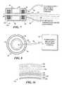
- FIG. 8shows a bottom view of the external coil shown in FIG. 7 .
- FIG. 9shows a cut-away side elevational view of an alternative external coil and a side elevational view of a graft, showing an integrated spiral RF coupling coil within the wall of the graft.
- FIG. 10shows a cut-away side elevational view of a further embodiment of an external coil and a side elevational view of a graft that includes a saddle-shaped RF coupling coil integrated within the wall of the graft.
- FIG. 11shows an embodiment of a woven spiral mesh RF coupling coil that is integrally provided in a wall of a graft.
- FIG. 12shows a cut-away view of a graft implantable at a substantial depth within a patient's body, showing an external coupling coil that encompasses the portion of the patient's body in which the graft is disposed.
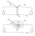
- FIG. 13shows a side elevational schematic view of a dual beam conformal transducer array on a carrier band for use around a fluid carrying vessel, in accord with the present invention.
- FIG. 14shows an end elevational view of the conformal transducer array of FIG. 13, around a vessel.
- FIG. 15shows a plan view of the conformal transducer array shown in FIGS. 13 and 14, cut along a cut line to display the dual conformal arrays in a flat disposition.
- FIG. 16shows an enlarged partial transverse cross-sectional view of the layers comprising the conformal transducer array mounted on a carrier band that is disposed around a vessel wall.
- FIG. 17shows an enlarged partial transverse cross-sectional view of the layers comprising the conformal transducer array disposed within a vessel wall of a synthetic graft.
- FIG. 18shows an enlarged partial cross-sectional side view of a tilted-element transducer array disposed within a wall of a synthetic graft.
- FIG. 19Ashows an enlarged partial cross-sectional side view of a pressure transducer disposed within the wall of a synthetic graft.
- FIG. 19Bshows an enlarged side elevational view of a graft in which are disposed a pair of pressure transducers.
- FIG. 20Ashows a cross-sectional side view of a portion of a synthetic graft in which are disposed transversely oriented transducers for monitoring flow using correlation measurements.
- FIG. 20Bshows a transverse cross-sectional view of the synthetic graft shown in FIG. 20 A.
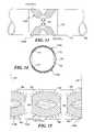
- FIG. 21illustrates an ultrasonic transducer configuration specifically designed to provide standing waves for sonochemical activation of blood-borne drug precursors.
- FIG. 22shows a side view of the ultrasonic transducer configuration of FIG. 21 and illustrates a physical linkage that couples to the transducer.
- FIG. 23illustrates a dual frequency ultrasonic transducer.
- FIG. 24illustrates an embodiment of a coil integrated into a graft.
- FIG. 25illustrates another embodiment of a coil integrated into a graft.
- FIG. 26illustrates a group of therapeutic transducers coupled to a tumor and controlled via an implanted electronic circuit such as that illustrated in any of FIGS. 1 through 6.
- the implanted system used for this purposewill very likely need to receive energy from an external source and must convey signals to or from a monitoring device that is disposed outside the patient's body.
- data signals to the implanted system to select transducers to trigger drug delivery or activation or indicating the status of fluid flow sensed by each separate transducermust be directed to each location of a selected transducer.
- only a single transducermay be required to monitor a parameter such as flow or velocity, which is indicative of the internal condition of the graft, or to provide localized drug therapy or localized drug activation.
- implanted and implantableare used herein to describe implanted or implantable devices that are intended to be permanently emplaced within a patient's body but that may be removed or replaced at a later date for a variety of reasons, and to distinguish these types of devices from devices, such as angioplasty catheters, stent delivery catheters and the like which are inserted into the body for relatively short periods of time.
- FIG. 1illustrates a first embodiment of an implantable electronic circuit for localized drug delivery or activation or for monitoring flow, applicable to the situation in which n transducers 44 - 46 are included on one or more vessels or vessel grafts in the patient's body. Variations of the implantable electronic circuit shown in FIG. 1 are discussed below to accommodate specific conditions. In addition, other embodiments of implantable electronic circuits are illustrated in FIGS. 2 through 6. These embodiments, like that of FIG. 1, are useful for providing power to transducers that locally dispense or activate drugs or monitor fluid flow or velocity through a vessel, and for transmitting data signals from the transducers 44 - 46 to a monitoring console outside a patient's body.
- implantable electronic circuitsare better suited for certain situations than others, and again, variations in the implantable electronic circuits are discussed below, as appropriate.
- implantable telemetry systemsare discussed in A Telemetry - Instrumentation System For Monitoring Multiple Subcutaneously Implanted Glucose Sensors by M. C. Shults et al., IEEE Trans. Biomed. Eng., Vol. 41, No. 10, October 1994, pp. 937-942 and Integrated Circuit Implantable Telemetry Systems by J. W. Knutti et al., Eng. in Med. and Bio. Magazine, March 1983, pp. 47-50.
- FIGS. 1 through 6are intended to be implanted within the patient's body and left in place at least during the period in which therapy is necessary. Although separate functional blocks are illustrated for different components of the implantable electronic circuits in these Figures, any of the implantable electronic circuits can be implemented in one or more application specific integrated circuits (ASICs) to reduce size, which is particularly important when the implantable electronic circuits are integral with a graft.
- ASICsapplication specific integrated circuits
- the implantable electronic circuitscan be either included within the wall of a vessel, or in the wall of a graft in the case of a synthetic (i.e., man-made) graft, or may be simply affixed to or implanted adjacent to the graft for either natural vessels, man-made grafts or natural grafts that comprise a portion of a vessel taken from a different location in the patient's circulatory system. Additionally, the implantable electronic circuits may be coupled to a transducer 44 - 46 that is in turn coupled either to an organ or tumor or to a blood vessel that supplies blood to an organ or tumor where localized drug activation potentially provides therapeutic advantages.
- Each of the implantable electronic circuits shown in FIGS. 1 through 6includes a RF coupling coil 30 , which is coupled via lines 34 and 36 to a RF-to-DC power supply 32 .
- the RF-to-DC power supply 32rectifies and filters a RF excitation signal supplied from an external source to the RF coupling coil 30 , providing an appropriate voltage DC power signal for the other components of the implantable electronic circuits illustrated in these Figures.
- the RF-to-DC power supply 32would only require rectifiers and filters as appropriate to provide any needed positive and negative supply voltages, +V s and ⁇ V s .
- the RF-to-DC power supply 32may provide for a DC-to-DC conversion capability in the event that the electromagnetic signal coupled into the RF coupling coil 30 fails to provide the required DC voltage level for any component. This conversion capability increases the lower voltage produced by the direct coupling of the external RF excitation signal received by the RF coupling coil 30 , to a higher DC voltage. Details of the RF-to-DC power supply 32 are not shown, since such devices are conventional. It is also contemplated that it may be necessary to limit the maximum amplitude of the RF input signal to the RF-to-DC power supply 32 to protect it or so that excessive DC supply voltages are not provided to the other components.
- each component that must be provided with a limited DC voltage supplymay include a voltage limiting component, such as a zener diode or voltage regulator (neither shown).
- the RF coupling coil 30 and the RF-to-DC power supply 32 of FIGS. 1 through 6may be replaced by a hard-wired connection to supply DC or AC power in applications where the implant is needed for a relatively short duration where the inconvenience of the cables supplying the power is tolerable and the risk of infection is manageable.
- An example of a hard-wired transcutaneous connection for chronic implantsis described in Silicon Ribbon Cables For Chronically Implantable Microelectrode Arrays by J. F. Hetke et al., IEEE Trans. Biomed. Eng., Vol. 41, No. 4, April 1994, pp. 314-321.
- the RF-to-DC power supply 32may include a battery or a capacitor for storing energy so that the RF coupling coil 30 need not be energized by a power signal in order for the implantable electronic circuit to operate, or at least, should include sufficient storage capability for at least one cycle of receiving energy and operating to deliver or activate drugs, or for transmitting data indicative of graft or vessel status to locations outside the patient's body. Neither a battery nor power storage capacitor are illustrated in the Figures, since they are conventional also.
- Implantable electronic systems using battery powermay only require the ability to receive data and control signals and may include the ability to transmit signals. As a result, they do not necessarily require access to the skin, which facilitates efficient coupling of power signals.
- a battery-powered systemmay result in a very compact implanted system.
- a battery-powered systemthat also is capable of recharging the battery via power signals coupled through an implanted coil can permit continuing treatment or diagnosis without requiring that a physician be present throughout the treatment or requiring the patient to be in the medical facility.
- a RF decode section 40which is used for generating control signals that are responsive to information encoded in the external RF excitation signal received by the RF coupling coil 30 . This information can be superimposed on the RF excitation signal, e.g., by amplitude or frequency modulating the received signal.
- the RF decode section 40may also include a RF oscillator for providing the RF signals to the transducers 44 - 46 or for coupling signals from the transducers 44 - 46 to external electronic apparatus.
- the RF excitation frequencyis the same as the frequency used to provide energy for localized drug activation or for coupling of diagnostic signals.
- the energyis used to excite a selected ultrasonic transducer 44 - 46 to produce an ultrasonic wave that propagates through a vessel graft, organ or tumor that is being treated, or a vessel supplying blood to an area that is being treated, or for conveying data from that transducer 44 - 46 receiving the ultrasonic waves.
- This approachgenerally simplifies the implantable electronic circuitry but may not provide optimal performance. Therefore, FIGS.
- the RF excitation frequency used to provide power to the RF-to-DC power supply 32 and to provide control signals to the RF decode section 40is decoupled from the frequency that is used for exciting the transducers 44 - 46 and for modulating the data that they may provide in order to enable transmission to a point outside the patient's body.
- line 36 from the RF coupling coil 30is coupled to a multiplexer (MUX) 38 to convey signals to or from a selected one of a plurality of n transducers 44 - 46 that are coupled to the MUX 38 .
- the RF decode section 40provides a control signal to the MUX 38 through MUX control lines 42 to select that transducer 44 - 46 which will provide the data signal related to the status of flow through the graft being monitored.
- the RF decode section 40provides a control signal to the MUX 38 through MUX control lines 42 to select that transducer 44 - 46 which provides energy for localized drug activation.
- the control signalcauses the MUX 38 to select the specific transducer 44 - 46 that is to be excited by the RF signal received by the RF coupling coil 30 and further causes the MUX 38 to select the transducer 44 - 46 that will be employed to deliver or activate drugs.
- transducers 44 - 46may be employed for diagnostic or therapeutic purposes.
- the implantable electronic circuit shown in FIG. 1can also be used in connection with pressure transducers.
- the implantable electronic circuitis perhaps more applicable to the Doppler type for use in monitoring fluid velocity through a graft. If a single-vessel pulse Doppler transducer is used, the same transducer 44 - 46 can be used for both transmission and reception of the ultrasonic wave, thereby eliminating the need for the MUX 38 .
- the transducers 44 - 46 shown in FIG. 1are used for transit time flow measurements, it will normally be necessary to use the MUX 38 to switch between the transducer 44 - 46 used for transmitting the ultrasonic wave and that transducer 44 - 46 which is used to receive the ultrasonic wave.
- a pair of opposed transducers 44 - 46 that are disposed on opposite sides of the graftare typically used.
- the direction of the ultrasound wave propagationmust be known, i.e., the direction in which the ultrasound wave propagates relative to the direction of fluid flow through the vessel.
- the MUX 38is required.
- the transducers 44 - 46 that are disposed on opposite sides of the graftcan be electrically coupled in parallel or in series, eliminating any requirement for the MUX 38 .
- the RF-to-DC power supply 32 and the RF decode section 40could also then be eliminated, since the retarded and advanced transit time signals would be superimposed on the same RF waveform transmitted by the RF coupling coil 30 to locations outside the patient's body.
- this modification to the implantable electronic circuit shown in FIG. 1would not permit the direction of fluid flow through a graft to be determined, the retarded and advanced transit time signals interfere over time, and this interference can be used to estimate the magnitude of fluid flow through the graft.
- a single transducer 44 - 46 or group of transducers 44 - 46may be employed, in which case the implantable electronic circuit of FIG. 1 may be simplified by coupling the transducer(s) 44 - 46 directly to the RF coupling coil 30 and eliminating the MUX 38 .
- the RF decode section 40 and the RF-to-DC power supply 32are optional; if the transducer 44 - 46 , for example, requires DC excitation or other excitation different than that which may be provided directly via the RF coupling coil 30 , inclusion of the RF-to-DC power supply 32 may be desirable. Similarly, some sensors may have more than one function and then the RF decode section 40 may also be desirable.
- the implantable electronic circuits of FIGS. 2 through 6may be modified to provide the desired or required functionality.
- an implantable electronic circuituses a transmit multiplexer (TX MUX) 50 and a receive multiplexer (RX MUX) 54 .
- a transmit (TX) switch 48 and a receive (RX) switch 52couple line 36 to the TX MUX 50 and RX MUX 54 , respectively.
- the RF decode section 40responds to instructions on the signal received from outside the patient's body by producing a corresponding MUX control signal that is conveyed to the TX MUX 50 and the RX MUX 54 over the MUX control lines 56 to select the desired transducers 44 - 46 .
- the TX switch 48couples the RF excitation signal received by the RF coupling coil 30 to the activated transducer 44 - 46 that is selected by the TX MUX 50 .
- the TX switch 48allows excitation signals to pass to the selected transducer 44 - 46 only when the signals are above a predetermined voltage level, for example, 0.7 volts. Signals below that predetermined voltage level are blocked by the TX switch 48 .
- the RX switch 52couples that transducer 44 - 46 selected by the RX MUX 54 to the RF coupling coil 30 and passes only signals that are below the predetermined voltage level, blocking signals above that level.
- the RF signal used to excite a first transducer 44 - 46 selected by the TX MUX 50passes through the TX switch 48 and the lower amplitude signal produced by a second transducer 44 - 46 selected by the RX MUX 54 to detect a response to the ultrasonic signal transmitted through the graft is conveyed through the RX MUX 54 and the RX switch 52 and transmitted outside the patient's body through the RF coupling coil 30 .
- the implantable electronic circuit shown in FIG. 3is similar to that of FIG. 2, but it includes a transmit amplifier (TX AMP) 58 interposed between the TX switch 48 and the TX MUX 50 and a receive amplifier (RX AMP) 60 interposed between the RX MUX 54 and the RX switch 52 .
- TX AMPtransmit amplifier
- RX AMPreceive amplifier
- the TX AMP 58amplifies the excitation signal applied to the transducer 44 - 46 selected by the TX MUX 50 for producing the ultrasonic wave that is propagated through a graft or vessel.
- the RX AMP 60amplifies the signal produced by the transducer 44 - 46 selected by the RX MUX 54 before providing the signal to the RX switch 52 for transmission to locations outside the patient's body.
- the circuit shown in FIG. 3is most applicable to transit time flow measurements and employs the same frequency for both the RF excitation signal that supplies power to the RF-to-DC power supply 32 and the signal applied to a selected one of the transducers 44 - 46 to generate the ultrasonic wave propagating through the graft or vessel.
- the implantable electronic circuits shown in FIGS. 4 through 6enable the RF excitation frequency applied to the RF-to-DC power supply 32 to be decoupled from the frequency of the signal applied to excite any selected one of the transducers 44 - 46 .
- the signal produced by the transducer 44 - 46 receiving the ultrasonic waves propagating through the graft or vesselmay be at a different frequency than the RF excitation frequency.
- a transmitter (XMTR) 62 and a receive modulator/transmitter (RX MOD/XMTR) 64are coupled to and controlled by a RF decode/control section 66 .
- the RF decode/control section 66determines when the excitation frequency is generated for application to a selected transmit transducer 44 - 46 .
- the RF decode/control section 66also determines when the signal produced by the transducer 44 - 46 selected to receive the ultrasonic wave is used for modulating the RF signal applied to the RF coupling coil 30 .
- An advantage of this approachis that the RF power delivered to the RF coupling coil 30 may be chosen to be at an optimal frequency for penetration through the patient's body, thereby improving the efficacy with which the RF energy couples to a specific depth and location within the body. Another reason is for satisfying any requirements for selecting a particular frequency to comply with radio frequency allocation bands for medical equipment.
- the frequency applied to any selected transducers 44 and 46 to stimulate themcan be optimal for that purpose. Assuming that the two frequency bands, i.e., the RF excitation frequency band for the signal applied to the RF-DC power supply 32 and the frequency band applied to excite the transducers 44 - 46 , are sufficiently separated, the RF power delivery can occur simultaneously with the excitation of a selected transducer 44 - 46 and the generation of diagnostic signals by another selected transducer 44 - 46 . Accordingly, more RF power can be coupled into the system from the external source than in the implantable electronic circuits shown in FIGS. 1 through 3.
- the control signals that are supplied to the RF decode/control section 66 via the RF coupling coil 30can be conveyed using nearly any kind of modulation scheme, e.g., by modulating the RF excitation that powers the device, or by sending a control signal on a separate and distinct RF frequency.
- the signals that are received from the transducer 44 - 46 in response to the ultrasonic wave that is propagated through the graftcan be transmitted through the RF coupling coil 30 at a different frequency than the incoming excitation frequency, thereby eliminating interference between the RF-to-DC power supply 32 and data signal transmission functions.
- the implantable electronic circuit shown in FIG. 4is applicable to transit time flow measurements in which pairs of transducers 44 - 46 are selected for transmitting and receiving the ultrasonic wave that propagates through the one or more grafts or vessels on which the transducers 44 - 46 are installed.
- the RF decode/control section 66can be employed to control the TX MUX 50 and the RX MUX 68 to interchange the transducers 44 - 46 used for transmission and reception of the ultrasonic wave on successive pulses.
- the direction of the ultrasonic wave propagation through the graft or vesselis changed on alternating pulses of ultrasonic waves, enabling transit time difference information to be gathered without requiring further multiplexer programming information to be transmitted between successive ultrasonic wave pulses.
- This approachgreatly improves the data gathering efficiency of the implantable electronic circuit shown in FIG. 4 compared to the previously described implantable electronic circuits of FIGS. 1 through 3.
- FIG. 5To further improve the implantable electronic circuit shown in FIG. 4 for use in sensing fluid velocity through a graft using a Doppler technique, the modification shown in FIG. 5 is made.
- a TX/RX switch 72is added so that the implantable electronic circuit transmits and receives through the same transducer 44 - 46 .
- separate transmit and receive multiplexersare not required.
- the MUX 38is used to select the specific transducer 44 - 46 for receiving the RF excitation signal produced by the XMTR 62 so that the transducer 44 - 46 produces energy, e.g., an ultrasonic wave and then receives the response from fluid flowing through the graft to produce a receive data signal that is output through the RX MOD/XMTR 64 .
- the TX/RX switch 72prevents the signal applied by the TX AMP 58 from overdriving the input to the RX AMP 60 , effectively isolating the RX AMP 60 during the time that the signal is applied to the transducer 44 - 46 to excite it so that it produces the desired response.
- the signal detected by the transducer 44 - 46is allowed to reach the RX AMP 60 when the TX/RX switch 68 changes state (from transmit to receive).
- the implantable electronic circuit shown in FIG. 5has the same benefits as described above in connection with the implantable electronic circuit shown in FIG. 4 .
- the RF decode/control section 66responds to the information received from outside the patient's body that determines which one of the transducers 44 - 46 is selected at any given time by producing an appropriate MUX control signal that is supplied to the MUX 38 over the MUX control lines 56 .
- the RF decode/control section 66may cause the MUX 38 to select a different transducer 44 - 46 for producing/receiving ultrasonic waves after a predefined number of transmit/receive cycles have elapsed. For example, a different transducer 44 - 46 may be selected after eight cycles have been implemented to transmit an ultrasonic wave into the graft and to receive back the echoes from the fluid flowing through the graft. By collecting data related to the status of flow through one or more grafts in this manner, it becomes unnecessary to send programming information to the RF decode/control section 66 after each cycle of transmission of the ultrasonic wave into the fluid in the graft and reception of the echo.
- FIG. 6illustrates an implantable electronic circuit that is particularly applicable for use with transducers 44 - 46 comprising pressure sensors.
- Silicon pressure sensors designed to be installed on the radial arteryare available from the Advanced Technologies Division of SRI of Palo Alto, Calif.
- such pressure sensorscould be disposed within the wall of a synthetic graft to sense the pressure of fluid flowing through the graft at one or more points.
- the MUX 38selects a specific pressure transducer 44 - 46 to provide a data signal that is transmitted to the outside environment via the RF coupling coil 30 .
- a modulator/transmitter (MOD/XMTR) 70receives the signal from the transducer 44 - 46 selected by the MUX 38 in response to the MUX selection signal provided over the MUX control lines 56 from the RF decode/control section 66 , and, using the signal, modulates a RF signal that is supplied to the RF coupling coil 30 .
- the RF signal transmitted by the RF coupling coil 30thus conveys the data signal indicating pressure sensed by the selected transducer 44 - 46 .
- FIGS. 7 through 12illustrate details of several different embodiments for the RF coupling coil 30 that is implantable within a patient's body for receiving RF energy to provide power for the implantable electronic circuits discussed above for receiving control signals, or for transmitting data from the transducers 44 - 46 , such as relating to the condition of flow through one or more grafts that have been installed within the patient's vascular system.
- Optimization of RF coupling between the implanted RF coupling coil 30 (FIGS. 1 through 6) and an external coil 90 (FIG. 7)is partially dependent upon the propagation characteristics of the human body. Since the body tissue largely comprises water, the relative dielectric constant of mammalian soft tissues is approximately equal to that of water, i.e., about 80.
- the relative permeability of tissue comprising a bodyis approximately equal to one, i.e., about that of free space.
- the velocity of propagation of a RF signal through the bodyis proportional to the inverse square root of the dielectric constant and is therefore about 11% of the velocity of the signal in free space. This lower velocity reduces the wavelength of the RF signal by an equivalent factor.
- the wavelength of the RF signal transferred between the implantable RF coupling coil 30 and the external coil 90is a design consideration when the separation distance between the two is approximately equal to or greater than one-quarter wavelength. However, at the frequencies that are of greatest interest in the present invention, one-quarter wavelength of the RF coupling signal should be substantially greater than the separation distance between the two coils.
- the implantable electronic circuitincludes the RF coupling coil 30 and a transducer 44 - 46 , but does not include active electronic circuitry
- the external systeme.g., external power supply and patient monitoring console 100 , FIG. 8, below
- the external and internal coilsare aligned, the inductance and the resistance of the external coil are maximized.
- the frequency of the signal that is used for adjusting the alignmentmay be different than the frequency that is used to provide electrical signals to the transducer.
- the implantable electronic circuitmay include an additional component to facilitate sensing of alignment between the two coils.
- a metal disc in the implantmay be detected and localized by inducing an eddy current in the disc.
- the external power supply and patient monitoring consolemay then detect the magnetic field generated by the eddy current in the disc, much as a metal detector operates. Using different frequencies for the location and therapeutic functions may avoid energy losses caused by the eddy currents.
- a circuitmay be included with the therapeutic transducer and RF coupling coil that measures the amplitude of the signal from the external power supply and patient monitoring console that is induced in the RF coupling coil.
- a signalis transmitted from the implantable electronic circuitry to the external power supply and patient monitoring console, where a display provides an indication of the coupling. The operator may adjust the position of the external coil to optimize coupling between the two coils.
- MRImagnetic resonance imaging
- RF excitation and frequencies used for communicating data related to the fluid flow through a graftcan be up to about 40 MHz, although higher frequencies up to as much as 100 MHz may be feasible.
- the wavelength of the RF excitation signal in tissueis about 82 cm, which is just that point where wavelength considerations become important.
- RF excitation at a much higher frequencymay be feasible.
- access grafts that are used for hemodialysisare typically only about 5 mm beneath the surface of the skin, in the forearm of the patient.
- a RF coupling coil 30 Ais shown disposed opposite the corresponding external coil 90 .
- the RF coupling coil 30 Aincludes a toroidal coil 82 that is wound in the hollow center channel of a toroidal shaped core 84 .
- the core 84 and the toroidal coil 82are contained within a biocompatible housing 80 that also provides RF shielding around the RF coupling coil 30 A except where it lies opposite to the external coil 90 .
- the external coil 90is of similar design, including a toroidal coil 92 disposed within the hollow center portion of a toroidal shaped core 94 .
- a housing 96 comprising a RF shieldencloses much of the toroidal coil 92 and the core 94 .
- a cable 98conveys signals to and from an external power supply and patient monitoring console 100 , which is shown in FIG. 8 .
- the external coil 90 and the RF coupling coil 30 A shown in FIGS. 7 and 8represent one embodiment used for coupling electrical energy and conveying data signals across a skin interface 102 for applications in which the RF coupling coil 30 A is implanted in tissue 104 that is relatively close to the surface 102 of the skin.
- the RF coupling coil 30 A and the external coil 90would provide the coupling required for a system used to monitor coronary artery bypass grafts (CABG).
- CABGcoronary artery bypass grafts
- the external core 94 and the internal core 84need not be identical in size and shape, it is generally true that coupling will be optimal when the annular surfaces of the two cores 94 and 84 are of approximately the same dimensions and when the core halves 94 and 84 are aligned.
- the external coil 90By observing the strength of the signal transmitted from the RF coupling coil 30 A, it should be possible to position the external coil 90 in proper alignment with the implanted RF coupling coil 30 A so that the amplitude of the signal is maximized.
- the material usedshould have a relatively high magnetic permeability, at least greater than one.
- ferriteis commonly used for core materials, sintered powdered iron and other alloys can also be used.
- the choice of materials for the cores of the RF coupling coil 30 A and the external coil 90 based on the magnetic characteristics of such materialsis generally conventional.
- the housing 96 on the external coil 90provides RF shielding against electromagnetic interference (EMI).
- the housing 96is conductive, grounded and surrounds the external coil 90 except where the surface of the core 84 is opposite the core 94 of the implantable RF coupling coil 30 A.
- the RF shield comprising the housing 96also optionally includes a split annular ring 116 , which is attached to the internal shield (not separately shown) at the cable 98 .
- a similar split annular ring 86is optionally provided on the RF coupling coil 30 A covering the toroidal core 82 .
- Split annular rings 86 and 116are used so that a continuous loop acting as a shorted turn is avoided that would otherwise tend to attenuate coupling between the external coil 90 and the RF coupling coil 30 A.
- the housing 80 of the implantable RF coupling coil 30 Ais coupled to the shield on a cable 88 , and the shield is coupled to a shield on the implantable electronic circuit and the transducers 44 - 46 .
- the shield on the cable 98is connected to ground.
- the RF shields on both the external coil 90 and the implantable RF coupling coil 30 A, along with the shields provided around the transducers 44 - 46 (described below)minimize external EMI radiation due to the use of the present invention within a patient's body, and minimize impact of electromagnetic fields in the patient's environment or the implanted electronic circuit.
- a cylindrical RF coupling coil 30 Bis illustrated that comprises a plurality of spiral conductor coils 108 disposed within the wall of a graft 106 .
- the RF coupling coil 30 Bis coupled to an implantable electronics assembly 110 that may include any of the implantable electronic circuits shown in FIGS. 1 through 6.
- the transducers 44 - 46are provided within the wall of, or on the external surface of, the graft 106 .
- the RF coupling coil 30 Bwould typically be used with those grafts that are disposed relatively close to the outer surface of the patient's body, for example, within tissue 104 immediately below the dermal layer 102 . In this disposition, the RF coupling coil 30 B more readily couples to an external coil 90 A.
- the external coil 90 A shown in FIG. 9has a generally C-shaped core 94 A about which is coiled a plurality of turns 92 A. Leads 98 pass through a housing 96 A that comprises a RF shield and connect the external coil 90 A to the power supply and monitoring system 100 of FIG. 8 . Lines of magnetic flux 112 intersect the spiral coils 108 on the RF coupling coil 30 B to provide electrical power for energizing the implantable electronic circuit 110 .
- the RF coupling coil 30 Bgenerates a magnetic field concentrated along the longitudinal axis of the graft 106 that is sensed by the external coil 90 A to convey data indicating the flow status of the fluid through the graft 106 to the power supply and monitoring system 100 of FIG. 8 .
- the core 94 A of the external coil 90 Ais fabricated of a ferrite core material, or other suitable alloy.
- the number of coils 92 A, the size of the wire, the size of the core 94 A and other parameterscan be determined for a particular frequency of operation using conventional transformer design criteria.
- a RF coupling coil 30 Cis illustrated that comprises a plurality of generally saddle shaped coils 114 disposed within the wall of the graft 106 . Again, the RF coupling coil 30 C is coupled to the implantable electronic circuit 110 . Although only a single layer of saddle shaped coils 114 is illustrated, it is contemplated that a plurality of such interconnected layers could be provided within the wall of the graft 106 .
- an external coil 90 Bis provided that includes a plurality of coils 92 B wrapped around a central portion of a generally E-shaped core 94 B. Leads 98 pass through a housing 96 B that comprises a RF shield and connect the external coil 90 B to the power supply and monitoring system 100 of FIG. 8 . Lines of electromagnetic flux 112 are thus produced between the central leg and each of the end legs of the core 94 B. It will therefore be apparent that this embodiment of the RF coupling coil 30 C and of the external coil 90 B achieve optimum coupling when the distance separating the two is minimal.
- the RF coupling coil 30 C and the external coil 90 Bare best used in applications where the graft 106 is disposed relatively close to the dermal layer 102 so that tissue 104 separating the graft 106 from the external coil 90 B is only a few centimeters thick.
- this embodiment of the RF coupling coil 30 C and the external coil 90 Bis applicable for use with access grafts implanted just beneath the skin on the patient's forearm. Maximal coupling is achieved when longitudinal axes of the external coil 90 B and the graft 106 are aligned.
- FIG. 11A further embodiment of a RF coupling coil 130 that is disposed within a graft 144 is shown in FIG. 11 .
- the RF coupling coil 130comprises a woven mesh 132 fabricated from insulated wire so that overlapping segments of the woven mesh 132 do not electrically connect in the center of the graft 144 .
- the wires comprising the woven mesh 132are electrically coupled together at nodes 134 , producing a multi-turn RF coupling coil 130 .
- the nodes 134are insulated from contact with body fluids or other conductors.
- the couplings at the nodes 134are preferably not made not made at random or haphazardly between the various wires comprising the woven mesh 132 .
- a first wire comprising a helical coil having, e.g., a first orientation (which may be called a “right hand spiral”)has a first end coupled to a first end of a second wire comprising a helical coil having a second orientation (“left hand spiral”; i.e., a mirror image of the right hand spiral).
- the voltage induced in the two wiresis equal, but opposite in sign, and the two wires are thus coupled in series and provide twice the voltage between their second ends than that produced between the first and second ends of either wire alone.
- the second ends of the first two wirescannot be coupled together at the other end of the woven mesh 132 if these two wires are to contribute to the total electrical energy derived from the woven mesh 132 . Rather, the wires must be “daisy chained” in series to provide one embodiment of the RF coupling coil 30 C.
- a first group of wires all having a right hand spiralmay all be coupled in parallel (i.e., have the ends at a first end of the woven mesh 132 coupled together, and the ends at a second end of the woven mesh 132 coupled together), with wires having a left hand spiral being similarly treated but in a second group.
- the groupsthen may be combined in series or in parallel, or subsets of the wires may be grouped and combined.
- Electrodes 136 and 138convey signals to and from nodes 134 , coupling the woven mesh 132 to the implantable electronic circuit 110 .
- a biocompatible coating 142surrounds the wires comprising the woven mesh 132 , protecting them from contact with bodily fluids.
- an alternative external coil 154can be employed, generally as shown in FIG. 12 .
- an artery 152includes a graft 144 comprising the RF coupling coil 130 , which is disposed within a thigh 150 of the patient.
- the graft 144may be implanted, for example, in the descending aorta, the iliac arteries or to provide therapy to a tumor that is deeply within the abdomen.
- the RF coupling coil 154includes a plurality of turns 156 sufficient in diameter to encompass the patient's thigh 150 .
- a RF shield 160encloses the outer extent of the RF coupling coil 154 , so the RF coupling coil 154 is insensitive to capacitively coupled noise.
- a lead 158couples the RF coupling coil 154 to the power supply and monitoring console 100 of FIG. 8 .
- the RF coupling coil 154can be made sufficiently large to encompass the portion of the body in which the implanted graft is disposed, such as the torso, another limb of the patient, or the neck of the patient.
- Couplingis maximized between the external coil 154 and the RF coupling coil 130 (or other RF coupling coil) used on the graft when the central axes of both the RF coupling coil 130 and the external coil 154 are coaxially aligned and when the implanted graft is generally near the center of the external coil 154 .
- Coupling between the two coilsdecreases with increasing separation and begins to degrade significantly when the implanted graft 144 is more than one external coil radius away from the center point of the external coil 154 .
- couplingis minimized when the central axes of the two coils are perpendicular.
- an ultrasonic transducer for monitoring flow or fluid velocity through a graftshould be relatively compact if it is to be mounted adjacent a natural graft or included in the wall of a synthetic graft.
- an ultrasonic transducerincludes an element comprising a regular solid such as a planar slab or disc of a piezoelectric material having conductive electrodes disposed on opposite sides thereof. Since such elements are relatively planar, they do not conform to the natural circular cross-sectional shape of a graft. Therefore, a graft incorporating such a transducer 44 - 46 that is implanted within a patient's body and which is intended to be left in place for an extended period of time requires modification of the graft or the transducer 44 - 46 or both.
- FIG. 13shows an embodiment of an extremely low profile ultrasonic transducer 44 - 46 comprising a conformal transducer array 174 A disposed on opposite sides of a graft or vessel 170 from a conformal transducer array 174 B.
- the conformal transducer arrays 174 A and 174 Bcomprise a piezoelectric plastic used as a transduction material and having sufficient flexibility to allow the transducer elements to be wrapped around a wall 168 of the vessel 170 .
- Such flexible piezoelectric plastic materialsare readily available.
- the vessel 170may comprise either a natural or synthetic graft, or may instead be simply a part of the patient's vascular system.
- the compact, low profile aspect of the conformal transducer array 174 Amakes it ideally suited for other applications outside the medical field. It is therefore contemplated that the conformal transducer array 174 A, 174 B shown in FIGS. 13, 14 and 15 may alternatively be used in other commercial and industrial applications in which space around the vessel wall 168 is at a premium and there is a need to monitor flow and/or velocity of a fluid through the vessel 170 .
- the conformal transducer array 174 Amay be used to monitor fluid flow or velocity through a plastic or metal pipe or tube.
- itcan be used for either transit time or Doppler measurements.
- the conformal transducer arrays 174 A and 174 Bare disposed generally on opposite sides of the vessel 170 and encompass much of the circumference of the vessel 170 .
- the conformal transducer array 174 Awhen a pulsed Doppler measurement is made using the conformal transducer array 174 A, only a single conformal transducer array 174 A is required, since it first produces an ultrasonic wave that is transmitted into the vessel 170 and then receives an echo reflected back from the fluid flowing through the vessel 170 .
- the pair of conformal transducer arrays 174 A and 174 B disposed on opposite sides of the vessel 170are needed, one transducer, e.g., 174 A, serving as a transmitter and the other, e.g., 174 B, serving as a receiver.
- the fluidhas a non-zero velocity component directed along an ultrasonic beam axis of the ultrasonic wave produced by the conformal transducer array 174 A serving as a transmitter.
- the conformal transducer arrays 174 A and 174 B shown in FIGS. 13 through 15produce ultrasonic beams 178 that are tilted relative to the transverse direction across the vessel 170 in substantially equal but opposite angles with respect to the longitudinal axis of the vessel 170 . Since dual beam transit time measurements are implemented by the conformal transducer arrays 174 A and 174 B, the results are self-compensating for tilt angle errors. This form of self-compensation is only required where the alignment of the conformal transducer arrays 174 A and 174 B relative to the longitudinal axis of the vessel 170 may be imperfect.
- a single conformal transducer arraye.g., 174 A
- a second such conformal transducer arraycan be used to gather velocity data along a second beam axis using pulsed Doppler velocity measurements. Assuming that the second axis is tilted in an equal but opposite direction as the first axis, the Doppler measurements made by the first 174 A and second conformal transducer arrays should be self-compensating for tilt errors.
- the second conformal transducer array(not shown) could be mounted on the same or on an opposite side of the vessel 170 from that where the first conformal transducer array 174 A is mounted to implement the Doppler measurements.
- the transit signalis applied for a sufficiently long period so that a second conformal transducer array is needed to receive the echo signals.
- a single set of diametrically opposed conformal transducer arrays 174 A and 174 Bcan be used.
- the conformal transducer arrays 174 A and 174 Bneed not wrap entirely around the vessel 170 .
- the conformal transducer arrays 174 A and 174 Beach span an arc of approximately 120° around the longitudinal axis of the vessel 170 (i.e., about the center of the circular vessel wall 168 as shown in FIG. 14 ).
- This geometryproduces a measurement zone through which ultrasonic beams 178 propagate that is nominally equal to about 87% of the vessel outer diameter. Since the vessel wall 168 has a finite thickness, the actual measurement zone (within the lumen of the vessel wall 168 ) exceeds approximately 90% of the vessel internal diameter.
- the conformal transducer array 174 Aneed cover only a central portion of the vessel 170 . As a result, the span of the conformal transducer array 174 A can be reduced from about 120° to something within the range from about 60° to about 90°.
- the conformal transducer array 174 Amust produce ultrasonic waves having a wave front characterized by a substantially uniform amplitude and phase.
- lateral projections through each of a plurality of transducer elements comprising the conformal transducer arrays 174 A and 174 Bare indicated by straight lines 176 . These straight lines indicate the centers of the transducer elements and are perpendicular to the axis of propagation of the waves 178 (represented by bidirectional arrows directed along the axes of propagation of the ultrasonic waves).
- the spacing between the element centersi.e., between the straight lines 176 , is approximately equal to a phase angle of 90° at the transducer's excitation frequency.
- transducer elements disposed along each of the displayed straight linesproduce acoustic waves that are successively delayed by 90°, or one-quarter wavelength in the fluid medium through which the ultrasonic waves propagate.
- a sound velocity of 1,540 meters/secondis normally assumed, so that the physical spacing of the projected straight lines would typically be defined by the following:
- the conformal transducer array 174 Aproduces a succession of ultrasonic waves spaced apart by a 90° phase shift, thereby achieving a uniform phase front across the conformal transducer array 174 A.
- phase shifts of 90°While the discussion herein is in terms of phase shifts of 90°, it will be appreciated that other types of transducer element spacings or relative displacements may require different phase shifts. For example, three phase transducers are known that employ a phase shift of 120° between adjacent elements. Additionally, physical displacements of the transducer elements in the direction of propagation of the acoustic waves may require different or additional phase shifts between the electrical signals coupled to the elements. It is possible to phase shift these signals to provide a uniform phase front in the propagating acoustic wave using conventional techniques.
- Amplitude uniformitycan be achieved in the ultrasonic wave front by apodizing or “shaving” the elements of the conformal array.
- shavingcould be achieved in a variety of ways, in one embodiment shaving is implemented by varying the area of each element.
- the conformal transducer arrays 174 A and 174 Bare carried on a band 172 made from the piezoelectric plastic material used for the element substrate, which is sized to fit snugly around an outer surface of the vessel 170 .
- the band 172is intended to position the conformal transducer arrays 174 A and 174 B in acoustic contact with the vessel wall 168 . Such contact assures that the ultrasonic waves produced by the elements of the conformal transducer arrays 174 A and 174 B are conveyed through the vessel wall 168 and into the fluid flowing through the interior of the vessel 170 .
- the piezoelectric plasticcomprising the band 172 , and more particularly, the conformal transducer arrays 174 A and 174 B, are fabricated from a material such as polyvinylidene fluoride (PVDF), poly(vinyl cyanide-vinyl acetate) copolymer (P(VCN/VAc), or poly(vinylidene fluoride-trifluoroethylene) copolymer (P(VDF-TrFE)).
- PVDFpolyvinylidene fluoride
- P(VCN/VAc)poly(vinyl cyanide-vinyl acetate) copolymer
- PVDF-TrFEpoly(vinylidene fluoride-trifluoroethylene) copolymer
- FIG. 15further details of the conformal transducer arrays 174 A and 174 B are illustrated.
- alternating elements of the conformal arrayproduce ultrasonic waves differing in phase by 90°.
- a cut line 175intersects the lateral center of the conformal transducer array 174 B. In practice, any cut would more likely extend through the band 172 at a point approximately midway between the conformal transducer array 174 A and the conformal transducer array 174 B.
- the elements comprising the conformal transducer arrays 174 A and 174 Bneed not be interrupted or damaged. Electrodes comprising each element of the conformal transducer array 174 A and 174 B can be photolithographically generated on the piezoelectric plastic substrate comprising the band 172 .
- the elementscan be formed on a non-piezoelectric material comprising band 172 , and then the material with the elements formed thereon can be bonded to a piezoelectric substrate in each area where a conformal transducer array 174 A or 174 B element is disposed.
- a flexible circuit materialsuch as a polyimide could be employed for the band 172 , and that conventional photolithographic processing methods might be used to fabricate the conformal transducer array circuitry on the band 172 .
- the centers of alternating conformal array elementsare coupled together electrically via conductors 180 (shown as dashed lines) in FIG. 15 .
- conductors 180shown as dashed lines
- FIGS. 13 through 15are the leads that extend from an electronics assembly used to drive the conformal transducer arrays 174 A and 174 B. Any of the implantable electronic circuits shown in FIGS. 1 through 6 could be used for the electronics assembly.
- the period of the sine wave from which these sinusoidal segments are derivedis approximately equal to the circumference of the band 172 .
- the amplitude of that sine wavegenerally depends on the desired beam angle relative to the longitudinal axis of the vessel 170 .
- the amplitudeis defined by:
- each conformal transducer array 174 A or 174 Bis defined by:
- ⁇is equal to the angle between the longitudinal axis of the vessel 170 and the ultrasound beam axis and D is equal to the external diameter of the vessel 170 .
- one sinusoidal templatecould be used to draw all of the transducer elements and a second sinusoidal template (differing only in amplitude from the first) could be used to draw the boundary of each conformal transducer array 174 A and 174 B.
- the transducer elementsare displaced or spaced apart from one another as required to achieve the phase relationship described above in connection with FIG. 13 .
- the actual physical electrode pattern and placement of the elements on the band 172can be determined by finding intersection loci between the band 172 as wrapped around the vessel 170 and equally-spaced planes. The spacing between these planes is defined by the equation noted above for the projected spacing.
- Conductors 180 that each connect to adjacent transducer elementsdiffer in phase from each other by 90°.
- a uniformly poled piezoelectric plastic substrateis used and every fourth element is connected together, producing four groups of elements or electrodes that produce ultrasonic waves having phase relationships of 0°, 90°, 180° and 270°, respectively.
- a zone poled piezoelectric plastic substratecould be used and every other element can be connected together (as shown in FIG. 15 ).
- Each of these two groupsis then connected to provide an in phase and a quadrature phase transceiving system, so that ultrasonic waves are produced by adjacent elements in each group have a relative phase relationship of 0° and 90°.
- a multi-layer interconnect patternis required to connect to all traces for each of the transducer elements in the four groups.
- a more complex four-phase electronic driving systemthat includes a phase shifter is required. Specifically, the signal applied to each of the four groups must differ by 90° between successive elements to achieve the 0°, 90°, 180° and 270° driving signals.
- the phase shiftermay be included in the modulator that drives the conformal transducer array 174 A and 174 B (which may be included as a part of the RF decode section 40 of FIGS. 1 through 3 or the RF decode/control section 66 of FIGS. 4 through 6) and provides the phase shifted excitation signals applied to each successive element of the conformal transducer arrays 174 A and 174 B.
- the piezoelectric plastic materialmust be locally poled in a specific direction, depending upon the desired phase of the electrode at that location.
- a poling directionreversal provides a 180° phase shift, eliminating the need for 180° and 270° phase-shifted signals.
- the zones of the substrate designated as 0° and 90°would be connected to the signal source with the elements poled in one direction, while zones for elements designated to provide a relative phase shift of 180° and 270° would be connected with the elements poled in the opposite direction.
- the elements producing ultrasonic waves with a relative phase relationship of 0° and 180°would comprise one group and the elements producing ultrasonic waves with a relative phase relationship of 90° and 270° would comprise a second group. Poling the different groups of elements in local regions in opposite directions is achieved by heating the material above the Curie temperature, applying electric fields of the desired polarities in each of those areas and then cooling the material below the Curie temperature while maintaining the electric fields. This occurs during manufacture of the conformal transducer arrays 174 A and 174 B.
- the final element wiring pattern required to actually energize the conformal transducer arrays 174 A and 174 B when they are employed for monitoring flow and/or velocity of fluid through the vessel 170would preclude applying electric fields in opposite polarity. Accordingly, the required poling relationship would have to be realized using either temporary electrodes or by providing temporary breaks in the actual electrode pattern employed in the final conformal transducer arrays 174 A and 174 B.
- the electrode masswould be increased to a point well beyond that required for making electrical connections. This added mass would act together with the piezoelectric plastic material to form a physically resonant system at a desired frequency. In this manner, a relatively thinner and more flexible piezoelectric plastic material can be used for the substrate comprising the band 172 .
- Use of mass loadingis conventional in the art of ultrasonic transducer design.
- a conductive layer 177(FIG. 14) is included.
- the conductive layer 177may be disposed on the inside of the band 172 as illustrated, the conductive layer 177 could also be placed between the conformal array transducer 174 A and the band 172 .
- the conductive layer 177is placed on the outside of the conformal array transducer 174 A and the electrodes are placed on the side towards the band 172 .
- the conformal array transducer 174 Acomprises a sandwich of two layers of piezoelectric plastic, with the driven electrodes disposed between the two layers of piezoelectric plastic, and a pair of ground planes are disposed one to either outside surface of the conformal array transducer 174 A.
- the transducerthen comprises a ground plane, a layer of piezoelectric plastic, a layer of driven electrodes, a layer of piezoelectric plastic and the other ground plane.
- This embodimenthas the advantage that the conformal array transducer 174 A is well shielded. Other arrangements will also be apparent to those of skill in the art.
- the conductive layer 177may be floating (a “virtual ground”) or may be coupled to a ground or common circuit (e.g., 34 , FIGS. 1 through 6 ).
- the conformal transducer arrays 174 A and 174 Bare used to receive ultrasonic waves, the conductive layer 177 should be coupled to a common circuit or ground to reduce noise and EMI.
- the conformal transducer arrays 174 A and 174 Bcan be formed on the band 172 , but alternatively, can be included within the structure of a synthetic graft.
- FIG. 16illustrates a portion of a cross-sectional view of the conformal transducer arrays 174 A and 174 B (not explicitly shown in FIG. 16) fabricated on the band 172 .
- the entire transducer assemblyis covered with an outer coating 190 made from a biocompatible material that serves as a barrier to protect the conformal transducer arrays 174 A and 174 B from bodily fluids.
- the outer coating 190comprises PARYLENETM material, available from Specialty Coating Systems of Indianapolis, Ind.
- Outer coatings 190comprising PARYLENETM material may be grown to a desired thickness via vapor coating.
- the outer coating 190is grown to a thickness of between 0.0001′′ to 0.0002′′ (2.5 to 5 microns).
- a RF shield 192comprising electrically conductive flexible material or a thin foil that provides RF shielding to minimize EMI radiated from the conformal transducer arrays 174 A and 174 B.
- An acoustic backing 194comprising a conventional syntactic foam, i.e., a polymer loaded with hollow microbubbles, also known as microspheres or microballoons, serves both for acoustic isolation and dampening and to minimize capacitive loading.
- the acoustic backing 194comprises one volume of EPOTEK 377 or 301-2 epoxy glue available from Epoxy Technology of Billerica, Mass. mixed, e.g., with two or more volumes of microballoons available from PQ Corp. of Parsippany, N.J. Microballoons such as PM6545 acrylic balloons having an average diameter of 100 microns are employed in one embodiment, with the acoustic backing being 10 to 20 microballoons thick (one to two mm).
- the acoustic backing 194has a relatively low dielectric constant (e.g., ⁇ 10), thereby reducing capacitive loading between a rear electrode 196 , a front electrode 200 and surrounding tissue.
- the acoustic backing 194thus insulates the transducer elements from the surrounding fluid and tissue in a capacitive sense and also in an acoustic sense.
- the next layercomprises the rear electrode 196 .
- the front electrode 200is spaced apart from the rear electrode 196 by a piezoelectric plastic layer 198 .
- the front electrode 200is also the conductive layer 177 of FIG. 14 .
- the piezoelectric plastic layer 198comprises the band 172 .
- the piezoelectric layer 198 (or the band 172 )has a relatively low dielectric constant, e.g., from about six to eight, compared to tissue (approximately 80).
- the rear electrode 196 and the front electrode 200comprise multi-layer structures (although separate layers are not shown).
- the electrodes 196 and 200include a metallic layer, for example, titanium, that bonds well to the piezoelectric plastic material, followed by a highly conductive layer, for example, copper, followed by an oxidation resistant layer, for example, gold, and includes other metallic barrier layers, where appropriate, to prevent reaction between these layers.
- a metallic layerfor example, titanium
- a highly conductive layerfor example, copper
- an oxidation resistant layerfor example, gold
- Such multi-layer systemsare conventional and are suited for use as the electrodes 196 and 200 in the conformal transducer arrays 174 A and 174 B.
- the front electrode 200is the “common electrode” for the transducer elements and serves as a RF shield.
- a front coating 202serves as an acoustic coupling between the conformal transducer arrays 174 A and 174 B and the vessel 170 about which they are applied.
- the front coating layer 202serves as a biocompatible layer, providing a barrier to fluid ingress into the conformal transducer arrays 174 A and 174 B.
- the transducer assemblycomprising each of the layers disclosed above is wrapped around and in contact with a vessel wall 203 as shown in FIG. 16 .
- a synthetic graft material 204provides the primary structure for the synthetic graft and is adapted to be installed in a patient's vascular system.
- the graft material 204comprises either a foamed fluoropolymer such as that sold by W. L. Gore Associates, Inc., or a fabric such as DACRON material.
- the graft material 204is characterized by a moderate attenuation of ultrasonic signals and a structure that is somewhat porous to bodily fluids.
- the outer coating 190comprising a biocompatible material that protects the transducer elements is disposed below the graft material 204 .
- the outer coating 190also protects other components of the transducer system from bodily fluids that may permeate the graft material 204 .
- the RF shield 192is disposed below the outer coating 190 to minimize transmission of EMI outside the patient's body.
- the acoustic backing 194is disposed between the RF shield 192 and the rear electrode 196 , and as described above, is a relatively lossy material.
- the piezoelectric material 198is coupled to the rear electrode 196 and to the front electrode 200 and comprises one of the flexible piezoelectric plastics noted above.
- the front coating 202is applied to the inner surface of the graft and transducer assembly and is selected for its biocompatibility, to withstand exposure to the bodily fluids flowing through the graft.
- adhesive layersmay be used between the various layers.
- certain layerssuch as the front and rear electrodes 200 and 196 will likely need not be adhesively coupled to the piezoelectric material 198 if photolithographically formed on the piezoelectric material 198 .
- Other layersmay not require an adhesive to couple to adjacent layers, e.g., if formed of a thermoset material that self bonds to an adjacent layer when set.
- FIG. 18An embodiment of a tilted element transducer 210 is illustrated in FIG. 18 .
- Each element comprising the tilted element transducer 210includes the rear electrode 196 and the front electrode 200 disposed on opposite sides of the piezoelectric material 198 .
- the tilted element transducer 210includes a plurality of elements like those shown in FIG. 18 that minimize the radial height (or thickness) of the tilted element transducer 210 .
- the tilted element transducer 210is built into the wall of the synthetic graft 204 , generally as shown in FIG. 18, and includes the outer coating 190 , which again serves the function of providing a biocompatible layer to protect the interior portion of the graft 204 and the transducer components contained therein from exposure to bodily fluids outside the graft 204 .
- the graft 204can serve as the biocompatible coating, with the tilted element transducer disposed on the outside of the graft 204 .
- the synthetic graft material 204which comprises the overall structure of the graft 204 , is outside the outer coating 190 .
- the RF shield 192extends over the tilted element transducer 210 within the protection provided by the outer coating 190 .
- the acoustic backing 194is disposed below the RF shield 192 .
- the rear electrode 196is disposed on the piezoelectric material 198 which in turn includes the front electrode 200 disposed on an opposite surface of the piezoelectric material 198 .
- An acoustic filler material 212is disposed between the front electrode 200 and a front coating 202 , on the interior surface of the synthetic graft 204 , and is used to fill in the cavities in front of the transducer elements.
- the acoustic filler material 212is characterized by a relatively low ultrasonic attenuation, so that it readily conveys the ultrasonic waves produced by the elements into the lumen of the graft 204 .
- its acoustic impedancewhich is approximately equal to sound velocity times density, is approximately equal to that of the fluid in the vessel.
- the velocity of sound in the acoustic filler material 212should also be close to that of the fluid flowing through the graft 204 so that the sound beam is not significantly deflected by the acoustic filler material 212 .
- an acoustic filler material 212 having a relatively low sound velocity compared to the fluidmay be used.
- the acoustic filler material 212acts as an acoustic lens that deflects the sound being produced by the tilted transducer elements.
- acoustic filler materials 212such as silicones or fluorosilicones, typically having sound velocities about 1000 meters per second (compared to a sound velocity of approximately 1540 meters per second for blood), may be used.
- Low velocity lensesare conventional. The benefit of using a low velocity acoustic filler material 212 is that the tilted transducer elements can be tilted about 30% less than would be required otherwise.
- the overall height of the tilted element transducer 210 portion of the synthetic graft 204can be made about 30% thinner than would be possible without the low velocity acoustic filler material 212 .
- the plurality of tilted elementsproduce an ultrasonic wave 214 that propagates at an angle relative to the longitudinal axis of the synthetic graft 204 , which is represented by a center line 216 in FIG. 18 .
- an artificial graft 220is illustrated in which pressure transducers 226 are incorporated within the wall of the graft 220 for monitoring the pressure of fluid passing through the graft 220 .
- the outer coating 190comprising biocompatible material is disposed between the graft material 204 and the pressure transducers 226 .
- the outer coating 190is employed to protect the pressure transducers 226 and other components of the transducer system from bodily fluids that may permeate the graft material 204 .
- two pressure transducers 226are employed, one being used for monitoring the proximal fluid pressure and the other for monitoring the distal fluid pressure.
- the pressure transducers 226are disposed adjacent the entrance and exit ends of the artificial graft 220 , respectively.
- the pressure transducer 226may comprise one of several different types of devices for sensing pressure. Such devices include an integrated circuit pressure sensor, a strain-type pressure sensor, such as a resistive strain gauge that responds to fluid pressure, etc. Various types of pressure sensing devices appropriate for incorporation in the wall of a graft are readily available from a number of different commercial sources, including SRI Center for Medical Technology of Palo Alto, Calif. Referring now to FIG. 19B, the graft 204 is illustrated coupled to a vessel 228 . The pressure transducers 226 are coupled via leads 232 to an implantable electronic circuit 230 , such as that illustrated in FIG. 6, as discussed above. A line 234 connects the circuit to a remotely disposed RF coupling coil (not shown in FIG.
- the interior surface of the synthetic graft 220includes an internal coating 224 that conveys pressure readily from the fluid flowing through an interior 222 of the artificial graft 220 to the pressure transducers 226 .
- the inner coating 224is biocompatible and comprises an elastomeric material.
- FIGS. 20A and 20Ban alternative approach for monitoring the velocity of a fluid through an interior 250 of a synthetic graft 240 is illustrated.
- a pair of ultrasonic transducers 242 A and 242 Bwhich may be conformal transducer arrays such as those illustrated in connection with FIGS. 13 through 15, or may be other types of ultrasonic transducers, are mounted in relatively close proximity within a wall 244 of the synthetic graft 240 .
- the ultrasonic transducers 242 A and 242 Bmay be disposed externally in contact with the outer surface of a natural graft (not shown).
- the ultrasonic transducers 242 A and 242 Beach produce a pulse and receive an echo back from fluid flowing through the interior 250 of the graft, the echoes being scattered from the fluid flowing therein.
- the signal received from the ultrasonic transducer 242 A in response to the echois correlated with a similar signal from the ultrasonic transducer 242 B, resulting in a time delay estimate.
- the velocity of the fluidis then computed by dividing a distance between the center of the ultrasonic transducer 242 A and the center of the ultrasonic transducer 242 B by the time delay that was determined from the correlation analysis. This is explained in more detail as follows.
- specklehas a similar meaning in ultrasonics as in optics. It results any time that narrow band illumination is used.
- Optical speckleis visible when a laser (e.g., a pointer) illuminates a plain white wall. When illuminated with wideband illumination, the wall appears white and smooth. When illuminated with laser light, the wall appears to have bright and dark spots, hence the term speckle.
- Acoustic speckleis visible in medical ultrasound images, when the system is used to image homogeneous soft tissues such as the liver.
- the acoustic speckle patternis stationary and constant unless the tissue or flood is moving with respect to the imaging system.
- the same phenomenonis exploited in Doppler systems. When the echo return from moving blood is constant, there is no observable Doppler shift in the echo signal.
- the bloodconsists of thousands of scatterers, and the ultrasound reflects from ensembles of these scatterers.
- the amplitude and phase of the echo, at a given range,depends on the local distribution of scatterers, which is random.
- the random signal of echo amplitude and phase at a given depthrepeats as the blood flows past the second ultrasonic transducer 242 B, if the spacing between the two ultrasonic transducers 242 A and 242 B is such that the ensembles of scatterers have not changed significantly, i.e., if the two ultrasonic transducers 242 A and 242 B are close enough to each other that turbulence has not significantly disrupted the ensembles of scatterers.
- the first ultrasonic transducer 242 Areceives an echo signal that provides a speckle “image”—where the distance from the ultrasonic transducer 242 A is along the vertical dimension in FIGS. 20A and 20B, and the successive echo returns are along the horizontal dimension.
- the two “images” from the two ultrasonic transducers 242 A and 242 Bare correlated in the horizontal dimension, and what results is an instantaneous map of travel time vs. depth.
- the sampling aperture for this systemis much shorter than the time required for a heartbeat. Accordingly, a series of measurements, which may be taken during the interval between two successive heartbeats, may be processed or compared to determine peak, minimum and average blood velocity when these data are desired.
- the echoes in a correlation type transducer system like that shown in FIGS. 20A and 20Bare not frequency shifted. Instead, the velocity signal is extracted by correlating the echo amplitude versus time signals for a pair of range bins. The velocity versus time is independently determined for each range bin, resulting in a time dependent velocity profile across the diameter of the synthetic graft 240 .
- a variety of therapeutic transducersmay be implanted that are responsive to and/or powered by the signals coupled into the implantable electronic circuits of FIGS. 1 through 6.
- One class of therapeutic transducersprovide utility by enabling localized delivery or activation of specific drugs for specific purposes.
- One advantage to localized activation of drugsis that the side effects associated with the drugs may be reduced by only providing the drug at the site requiring treatment. This is advantageous in many situations, including chemotherapy, where the drugs are toxic.
- U.S. Pat. No. 5,445,608 entitled Method And Apparatus For Providing Light - Activated Therapydescribes a photodynamic therapy achieved by photoactivation of suitable optically active drugs.
- the drugsare activated via catheter-mounted light emitters inserted at the site to be treated and providing light at the wavelength required in order to activate the drugs and at the location where the activated drugs are needed for therapeutic purposes.
- precursor substances that can be optically activated by being broken down into drug moleculesinclude long-chain cyanine dyes, dimers of phthalocyanine dyes and porphyrin compounds.
- a wide selection of solid state light sources including laser diodes and light emitting diodesis commercially available from a variety of vendors, including Motorola of Phoenix, Ariz.
- Laser diodes or light emitting diodesmay be employed as transducers 44 - 46 in any of the systems shown in FIGS. 1 through 6 to provide light for photoactivation of drugs within a patient's body via signals from the implantable electronic circuit in response to signals transmitted from the power supply and patient monitoring console 100 of FIG. 8 .
- one or more of the transducers 44 - 46 of FIGS. 1 through 6are ultrasonic transducers, several of which are described with respect to FIGS. 13 through 18.
- Sonochemical activation of hematoporphyrin for tumor treatmentis described by S. I. Umemura et al. in Sonodynamic Activation of Hematoporphyrin: A Potential Modality For Tumor Treatment , published in the 1989 IEEE Ultrasonics Symposium Proceedings, IEEE cat. no. 0090-5607/89/0000-0955, pp. 955-960.
- Sonodynamic activation at one or more specific body sites to provide local drug deliveryis possible when one or more of the transducers 44 - 46 of FIGS. 1 through 6 are designed to provide suitable ultrasonic signals and are implanted at the locations where drug activation provides therapeutic benefits.
- Sonodynamic effectsare nonlinear effects associated with the peak compression and expansion portions of the wave cycle; at lower frequencies, the time that the peak portions of the wave have to act is greater. For this reason, lower frequencies are preferred in some embodiments. Other embodiments increase peak forces by combining two or more ultrasonic waves.
- Sonodynamic activation of drug precursorsmay be effected via any of the transducers 174 A or 174 B of FIGS. 13 through 15, the piezoelectric material 198 of the graft of FIG. 17, the tilted element transducer 210 of FIG. 18 or the transducers 242 A and 242 B of FIGS. 20A and 20B. Sonodynamic activation may also be achieved by other transducers such as those described in connection with FIGS. 21 through 23 below.
- FIG. 21illustrates an ultrasonic transducer configuration 258 specifically designed to provide sonodynamic therapy via standing waves (shown as dashed lines).
- the standing wavesprovide sonochemical activation of bloodborne drug precursors via control signals coupled from the implantable electronic circuitry of any of FIGS. 1 through 6 by lines 261 .
- the ultrasonic transducer configuration 258is useful where local drug activation is desired in order to deliver the drug to either a tumor that is downstream of vessel 106 or when the downstream vasculature is the intended target for the activated drug.
- the vessel 106 or graftis contacted on a first surface by an implanted ultrasonic transducer 260 and on a second surface by a device 262 that may be either another ultrasonic transducer similar to the transducer 260 or an acoustic reflector.
- the ultrasonic transducer 260may be coupled to the implanted electronic assemblies using any of the approaches described in connection with FIGS. 1 through 6.
- the layer structure described in connection with FIG. 16is applicable to the transducer 260 .
- the piezoelectric material forming the transducer 260may comprise piezoelectric plastic materials such as PVDF, P(VCNNVAc) or P(VDF-TrFE), available from AMP Sensors of Valley Forge, Pa., or any of the piezoelectric ceramics, e.g., lead zirconium titanate.
- PZT-4 materialavailable from Morgan-Matroc of Bedford, Ohio provides high electroacoustic coupling and low acoustic losses.
- the piezoelectric plastic P(VDF-TrFE)provides high electroacoustic coupling and low acoustic losses.
- the transducer 260(and, when the device 262 is a transducer, the device 262 ) may be of the type described, for example, with respect to FIGS. 13 through 16 or 18 and 19 , or may be a slab type ultrasonic transducer similar to that shown and described in connection with FIG. 23, described below.
- the alignment between the transducer 260 and the device 262must be maintained in order to preserve parallelism of the surface of transducer 260 that faces the device 262 and the surface of the device 262 that faces the transducer 260 . It is also important to keep these surfaces opposed to each other, i.e., relative lateral motion of the transducer 260 and the device 262 must be inhibited.
- the result of maintaining this alignmentis to form an acoustic cavity analogous to an optical Fabry-Perot resonator. This is achieved, in one embodiment, with the arrangement shown in FIG. 22 .
- FIG. 22shows a side view of the ultrasonic transducer configuration 258 of FIG. 21 and illustrates a physical linkage 210 that couples the transducer 260 to the device 262 .
- the physical linkage 210is shaped to allow the wall of the vessel 106 to assume a natural curve.
- the physical linkage 210also maintains the spatial relationship of the transducer 260 with the device 262 , that is, maintains the acoustic emission surface of the transducer 260 in alignment with and facing the acoustically reflective surface or the acoustic emission surface of the device 262 . Maintaining this alignment requires that these two surfaces be parallel to each other.
- FIG. 22also shows biocompatible coatings 264 surrounding both the transducer 260 and the device 262 .
- the biocompatible coatings 264are analogous to the biocompatible outer coating 190 of FIG. 16 .
- the transducer 260may also include an acoustic backing analogous to the acoustic backing 194 of FIG. 16, disposed on the transducer 260 as described in conjunction with FIG. 16 .
- a low impedance reflectori.e., providing an acoustic reflection coefficient approaching ⁇ 1
- a high impedance reflectori.e., providing an acoustic reflection coefficient approaching +1
- Low-density foamse.g., analogous to the acoustic backing material 194 of FIG. 16
- aerogelsprovide low acoustic impedances suitable for use in acoustic reflectors
- rigid bodiessuch as metals or ceramics provide high acoustic impedances suitable for use in acoustic reflectors. Setting the thickness T R of the acoustic reflector to be an odd multiple of one quarter of an acoustic wavelength, as measured in the acoustic reflector material, increases the reflection coefficient of the acoustic reflector.
- methods for localized delivery of medication using ultrasonic activationinclude encapsulation of medications in delivery vehicles such as microbubbles, microspheres or microballoons, which may be ruptured to locally release the medications via localized energy provided by implanted transducers.
- the delivery vehiclesmay include magnetic material, permitting the delivery vehicles to be localized via an applied magnetic field, as described in U.S. Pat. No. 4,331,654 entitled Magnetically - Localizable, Biodegradable Lipid Microspheres.
- the device 262is formed from a magnetic ceramic or a magnetic metal alloy, and is also capable of acting as an efficient acoustic reflector.
- This embodimentallows localization of magnetic delivery vehicles (e.g., microbubbles, microspheres or microballoons) via the static magnetic field associated with the device 262 , followed by insonification of the delivery vehicles when appropriate via ultrasound emitted by the transducer 260 in response to signals from any of the implantable electronic circuits shown in FIGS. 1 through 6.
- the term “insonify”means “expose to sound” or “expose to ultrasound”; “insonification” is used to mean exposure to sound or ultrasound.
- microballoons or microspherescan provide localized heating, can rupture them to locally release drugs or drug precursors contained in the delivery vehicles or can trigger sonodynamic activation of drug precursors that are blood-borne or that are released when the delivery vehicles rupture.
- Microbubbles of various compositions and filled with various drugsare developed and manufactured by ImaRx Pharmaceutical Corp. of Arlington Ariz.
- An advantage that is provided by use of an implanted permanent magnet for localization of magnetic delivery vehicles in this embodiment and othersis that permanent magnets do not require a rechargeable energy source in order to function. In some embodiments, this can provide a way of reducing power needs from the RF-to-DC power supply 32 of FIGS. 1 through 6.
- the frequency of the ultrasound from the therapeutic transducercan be varied to enhance or to reduce cavitation resulting from the ultrasound emitted from the transducer. Suppression of cavitation via frequency modulation is described in U.S. Pat. No. 5,694,936 entitled “Ultrasonic Apparatus For Thermotherapy With Variable Frequency For Suppressing Cavitation.” Methods for suppression or enhancement of cavitation are described in U.S. Pat. No.
- Sonodynamic activation of drugs or sonically-induced microbubble rupturemay occur at reduced power levels when properly-phased collinear acoustic signals at two different frequencies are provided. This effect has been shown to be particularly advantageous when one signal is at a frequency that is the second harmonic of the other signal and the two signals have an appropriate phase relationship. Increased tissue damage for a given intensity of ultrasound has also been reported by S. I. Umemura in Effect Of Second - Harmonic Phase On Producing Sonodynamic Tissue Damage , published in the 1996 IEEE Ultrasonics Symposium Proceedings, IEEE cat. no. 0-7803-3615-1/96, pp. 1313-1318.
- FIG. 23illustrates an embodiment of a dual frequency ultrasonic transducer 270 .
- the dual frequency transducer 270is designed to provide two different frequencies of ultrasound, where one of the frequencies may be the second harmonic of the fundamental transducer frequency, when supplied with suitable electrical signals. The phases of the two signals may be adjusted by the implanted electronic circuit of FIGS. 4 through 6 and this may be in response to signals from the power supply and patient monitoring console 100 of FIG. 8 .
- the dual frequency transducer 270comprises a disc 272 of piezoelectric material, poled, for example, as indicated by direction arrow 278 .
- the disc 272has a diameter D and a thickness T x . Electrode 274 and electrode 276 are formed on opposed surfaces of the disc 272 as described in conjunction with the rear and front electrodes 196 and 200 of FIG. 16 above.
- the diameter Dis chosen to provide the desired fundamental transducer frequency via radial mode coupling while the thickness T x is chosen to provide the second harmonic of the fundamental transducer frequency via thickness mode coupling.
- the diameter to thickness ratio D/T xis approximately 2:1.
- Conventional mode chartsprovide more precise ratios for a variety of materials.
- the radial modecomprises radial particle motion primarily into and out from the center of the disc, i.e., perpendicular to the direction arrow 278 , and symmetric about a cylindrical axis of the disc 272 .
- the surfaces of the disc 272exhibit longitudinal motion (i.e., parallel to the direction arrow 278 ) because of the Poisson's ratio of the material.
- the thickness modecomprises particle motion parallel to the direction arrow 278 .
- acoustic energy propagating in the same direction at both frequenciesmay be coupled out of the disc 272 via the surfaces on which the electrodes 274 and 276 are formed.
- the acoustic radiating surface emitting the ultrasounddoes not include an electrode 294 or 296 .
- electrodesmay be disposed on the sidewalls, with ultrasound being emitted from the planar surfaces.
- the radial mode providing ultrasound at the fundamental transducer frequencymay be chosen to be a harmonic of the lowest radial mode of the transducer 290 .
- the transducer 290may then be designed to have a larger diameter D than is possible when the lowest radial mode corresponds to the fundamental transducer frequency. This allows a larger area to be insonified by both ultrasonic signals than is otherwise feasible.
- frequencies of 500 kHz and 1 MHzare chosen as the two output frequencies for the dual frequency transducer 270 .
- the disc 272comprises lead zirconium titanate (PZT)
- the diameter Dis about 4 mm and the thickness T x is about 2 mm.
- the resulting dual frequency transducer 270is small enough to be incorporated in an implantable device and yet also large enough to insonify a significant portion of the lumen of many blood vessels or grafts.
- a rectangular slabmay be substituted for the disc 272 .
- a lateral modemay then be used instead of the radial mode associated with the disc 272 to provide the resonance at the fundamental frequency, with the thickness mode providing the resonance at the second harmonic.
- Conventional mode chartsare used to select the ratios of the relevant dimensions.
- Coating a cylindrical sidewall of the disc 272 and one of the electrodes 274 and 276 with an acoustic absorber 280allows the other of the electrodes 274 and 276 to serve as an acoustic radiator.
- Choosing the acoustic absorber 280 to have a low relative dielectric constantreduces capacitive loading of the dual frequency transducer 270 by the patient's body, which, as noted above, has a high relative dielectric constant (approaching 80) and which also includes conductive solutions.
- Coating the acoustic absorber 280 with a grounded conductor 282 , selecting the electrode 276 to be a grounded electrode and selecting the electrode 274 to be a driven electrodereduces unwanted radiation of electromagnetic signals from the transducer 272 .
- a thin biocompatible coating 284(analogous to the outer coating 190 of FIG. 16) protects the dual frequency transducer 270 from exposure to biological matter without preventing radiation of ultrasound from the surface bearing the electrode 276 .
- Localized therapyinclude coupling a thermally-activated medication to carrier molecules that have affinity to tumor tissue.
- Localized heating of the tumor tissueenables selective activation of the medication in the tumor tissue, as described in U.S. Pat. No. 5,490,840 entitled Targeted Thermal Release Of Drug - Polymer Conjugates .
- Localized heatingmay be effected through ultrasound via an ultrasonic transducer, e.g., transducers 44 - 46 (FIGS. 1 through 6) implanted to allow insonification of the affected area. Higher acoustic frequencies provide shorter penetration depths, i.e., provide greater control over where the ultrasound and therefore the resultant heat is delivered. Additionally, heating is increased by ultrasonic cavitation in the presence of microbubbles, microspheres or microballoons.
- Other methods for providing localized magnetic forces or heatinginclude transducers 44 - 46 comprising coils.
- FIG. 24illustrates a coil 292 comprising saddle-shaped wires 293 integrated into a graft 106 , either natural or artificial, that may be used to magnetically capture microbubbles, microballoons or microspheres bearing drugs.
- Leads 294couple the coil 292 to the implantable electronic circuit of any of FIGS. 1 through 6.
- the implantable electronic circuits of FIGS. 4 through 6may provide advantages in this situation because the frequency of the signal providing power to the implantable electronic circuits may be different from the frequency of the signals to the transducers 44 - 46 . This may avoid a situation where the signals providing power to the implantable electronic circuits also result in release of drugs in the vicinity of the RF coupling coil 30 that is receiving the electrical power.
- a magnetic field represented by flux lines 296is generated.
- the magnetic fieldcaptures magnetic delivery vehicles (e.g., microbubbles, microspheres or microballoons) that have been introduced into the patient's bloodstream.
- the increased concentration of delivery vehicles in the target vicinitycan be used to provide local increases in delivery of drugs contained in the delivery vehicles.
- Delivery vehicles including medicationmay be localized via a magnetic field and ruptured via an oscillating magnetic field as described in U.S. Pat. No. 4,652,257 entitled Magnetically - Localizable, Polymerized Lipid Vesicles And Method Of Disrupting Same .
- Suitable magnetic fieldsmay be provided via application of RF or RF and DC electrical energy to the coil 292 .
- one or more of the transducers 44 - 46 of FIGS. 1 through 6comprise the coil structure 292 .
- the transducer 44 - 46 that is selectedis activated and is supplied with current to either trap the magnetic delivery vehicles so that they can be ruptured via signals provided from another selected transducer 44 - 46 (e.g., an ultrasonic transducer that ruptures microbubbles via cavitation), or an oscillating magnetic field may be superposed on the magnetic fields used to trap the delivery vehicles.
- another selected transducer 44 - 46e.g., an ultrasonic transducer that ruptures microbubbles via cavitation
- an oscillating magnetic fieldmay be superposed on the magnetic fields used to trap the delivery vehicles.
- a permanent magnet 290may be included with the coil 292 to provide a static magnetic field for localization of magnetic delivery vehicles.
- An oscillating magnetic fieldmay then be provided via signals supplied to the coil 292 to rupture the delivery vehicles under the control of the implanted electronic circuit of any of FIGS. 1 through 6, where the coil 292 acts as one of the transducers 44 - 46 .
- These embodimentsmay reduce power requirements for the implanted electronic circuit while retaining external control over when the drug or drug precursor is released via signals from the power supply and patient monitoring console 100 of FIG. 8 .
- Other types of coilse.g., analogous to coils 30 B, 30 C or 130 of FIGS. 9, 10 or 11 , may also be used instead of the coil 292 .
- FIG. 25illustrates another embodiment of a coil 292 A integrated into a graft.
- the coil 292 Ais analogous to the coil 292 of FIG. 24, but is shaped as a cylindrical coil rather than as a saddle-shaped spiral.
- Leads 294 Acouple wires 293 A comprising the coil 292 A to the implantable electronic circuit of any of FIGS. 1 through 6.
- a suitable currenteither AC or DC
- the coil 292 Amay be used to captures magnetic delivery vehicles that have been introduced into the patient's bloodstream.
- the coils 292 or 292 Amay comprise a resistive material.
- a local temperature riseis produced. This local temperature rise may be employed to rupture microbubbles having a melting point slightly above normal human body temperatures.
- One system using microbubbles having a controlled melting point to facilitate rupture of the microbubbles at predetermined localized areas within a patient's bodyis described, for example, in U.S. Pat. No. 4,558,690 entitled Method Of Administration Of Chemotherapy To Tumors .
- the localized heatingmay be provided by a structure similar to the cylindrical RF coupling coil 30 B of FIG. 9, the saddle RF coupling coil 30 C of FIG. 10, the RF coupling coil 130 of FIG.
- the heatingmay be supplied directly by RF excitation of the coils 30 B, 30 C, 130 , 292 or 292 A or it may be effected via the implanted electronic circuits of FIGS. 1 through 6. This may be in response to signals from the power supply and patient monitoring console 100 of FIG. 8 .
- delivery vehiclessuch as microbubbles, microballoons or microspheres can increase localized heating of tissue via rupture of the delivery vehicles caused by localized application of ultrasound, as discussed, for example, in Technical Report: Drug And Gene Delivery , Jul. 2, 1997, ImaRx Pharmaceutical Corp.
- FIG. 26illustrates a group of therapeutic transducers 300 A, 300 B . . . 300 N coupled to a tumor 302 and controlled via an implanted electronic circuit such as that illustrated in any of FIGS. 1 through 6 via leads 304 .
- the arrangement of FIG. 26provides utility where the physician determines that portions of the tumor 302 are inoperable or that it is not possible to remove all of the tumor 302 .
- Implanting therapeutic transducers 300 A . . . 300 N on the tumor 302 or on a blood vessel that supplies blood to the tumor 302allows localized drug activation of blood-borne precursors. This allows chemotherapy to be provided directly to the tumor 302 without requiring high systemic levels of the chemotherapy toxin.
- transducers 300 A . . . 300 Nmay be employed to facilitate ultrasonic activation through drug penetration into the tumor 302 via sonophoresis, i.e., ultrasound enhancement of drug penetration into body tissues.
- the transducers 44 - 46 of FIGS. 1 through 6may concentrate or activate medications by supplying heat, via resistive processes or insonification, or may employ light, magnetic fields or electrical fields for localized drug delivery or activation.
- the transducer 270 of FIG. 23is also suited to increasing drug penetration of drugs into, e.g., tumors 302 via an implanted electronic circuit such as any of those shown in FIGS. 4 through 6.
- a graftis implanted, for example, to correct a stenosis or to repair an aneurysm.
- tissue ingrowth at the ends of the graftcan lead to stenosis, which can lead to thrombus formation.
- Thrombosisthreatens the viability of the graft, and may require aggressive intervention using surgery or drugs. It is very undesirable to have to surgically resolve this situation if there is a viable alternative approach for relieving the blockage.
- One approachis to infuse the patient with thrombolytic drugs. This may lead to hemorrhagic consequences in other parts of the body, especially if the patient has had, for example, recent surgery.
- the graftincludes a transducer, such as an ultrasonic transducer, coupled to the implantable electronic circuit of any of FIGS. 1 through 6, the introduction of a thrombolytic drug into the bloodstream of the patient can be followed by generation of ultrasound within the graft via the transducer and under the control of an attending physician.
- a transducersuch as an ultrasonic transducer
- the thrombolytic druge.g., urokinase, streptokinase or tissue plasminogen activator
- the thrombolytic druge.g., urokinase, streptokinase or tissue plasminogen activator
- Localized drug release via rupture of delivery vehicles such as microbubblesis one option for such drug activation.
- Sonodynamic or photodynamic activation of drug precursors to locally increase bioactivityis another option for such drug activation.
- Increased biological uptake of drugs as a result of energy provided via a transducer, for example, via acoustic streaming, cavitation, cavitation microstreaming etc.,is a further option for localized drug treatment.
- the attending physicianmay be able to obtain information that is indicative of graft condition. This can allow the physician to more readily determine if the condition is treatable without resorting to invasive evaluation and intervention.
- Monitoring during non-invasive treatmente.g., via local drug activation accomplished through use of an implanted blood velocity or blood pressure transducer, may allow assessment of the progress of thrombolysis that may, in turn, permit successful noninvasive treatment without incurring undue risk to the patient.
Landscapes
- Health & Medical Sciences (AREA)
- Life Sciences & Earth Sciences (AREA)
- Engineering & Computer Science (AREA)
- Heart & Thoracic Surgery (AREA)
- Biomedical Technology (AREA)
- Public Health (AREA)
- General Health & Medical Sciences (AREA)
- Veterinary Medicine (AREA)
- Animal Behavior & Ethology (AREA)
- Medical Informatics (AREA)
- Pathology (AREA)
- Biophysics (AREA)
- Physics & Mathematics (AREA)
- Molecular Biology (AREA)
- Surgery (AREA)
- Radiology & Medical Imaging (AREA)
- Nuclear Medicine, Radiotherapy & Molecular Imaging (AREA)
- Vascular Medicine (AREA)
- Hematology (AREA)
- Computer Networks & Wireless Communication (AREA)
- Anesthesiology (AREA)
- Chemical & Material Sciences (AREA)
- Gynecology & Obstetrics (AREA)
- Bioinformatics & Cheminformatics (AREA)
- Medicinal Chemistry (AREA)
- Pharmacology & Pharmacy (AREA)
- Dermatology (AREA)
- Cardiology (AREA)
- Prostheses (AREA)
- Media Introduction/Drainage Providing Device (AREA)
Abstract
Description
Claims (56)
Priority Applications (4)
| Application Number | Priority Date | Filing Date | Title |
|---|---|---|---|
| US09/028,173US6585763B1 (en) | 1997-10-14 | 1998-02-23 | Implantable therapeutic device and method |
| PCT/US1999/002271WO1999042039A1 (en) | 1998-02-23 | 1999-02-03 | Implantable therapeutic device and method |
| EP99905662AEP1065978A4 (en) | 1998-02-23 | 1999-02-03 | Implantable therapeutic device and method |
| AU25772/99AAU2577299A (en) | 1998-02-23 | 1999-02-03 | Implantable therapeutic device and method |
Applications Claiming Priority (2)
| Application Number | Priority Date | Filing Date | Title |
|---|---|---|---|
| US08/949,413US5807258A (en) | 1997-10-14 | 1997-10-14 | Ultrasonic sensors for monitoring the condition of a vascular graft |
| US09/028,173US6585763B1 (en) | 1997-10-14 | 1998-02-23 | Implantable therapeutic device and method |
Related Parent Applications (1)
| Application Number | Title | Priority Date | Filing Date |
|---|---|---|---|
| US08/949,413Continuation-In-PartUS5807258A (en) | 1997-10-14 | 1997-10-14 | Ultrasonic sensors for monitoring the condition of a vascular graft |
Publications (1)
| Publication Number | Publication Date |
|---|---|
| US6585763B1true US6585763B1 (en) | 2003-07-01 |
Family
ID=21841980
Family Applications (1)
| Application Number | Title | Priority Date | Filing Date |
|---|---|---|---|
| US09/028,173Expired - LifetimeUS6585763B1 (en) | 1997-10-14 | 1998-02-23 | Implantable therapeutic device and method |
Country Status (4)
| Country | Link |
|---|---|
| US (1) | US6585763B1 (en) |
| EP (1) | EP1065978A4 (en) |
| AU (1) | AU2577299A (en) |
| WO (1) | WO1999042039A1 (en) |
Cited By (206)
| Publication number | Priority date | Publication date | Assignee | Title |
|---|---|---|---|---|
| US20020042571A1 (en)* | 1998-08-02 | 2002-04-11 | Super Dimension Ltd. | Navigable catheter |
| US20020164813A1 (en)* | 2001-05-04 | 2002-11-07 | Colvin Arthur E. | Electro-optical sensing device with reference channel |
| US20030163190A1 (en)* | 2002-02-25 | 2003-08-28 | Scimed Life Systems, Inc. | High temperature stent delivery system |
| US20030216681A1 (en)* | 1998-06-29 | 2003-11-20 | John Zhang | Sheath for use with an ultrasound element |
| US20040054385A1 (en)* | 2000-06-29 | 2004-03-18 | Lesho Jeffery C. | Implanted sensor processing system and method |
| US6743173B2 (en)* | 2000-03-10 | 2004-06-01 | Remon Medical Technologies Ltd | Systems and methods for deploying a biosensor in conjunction with a prosthesis |
| US20040122422A1 (en)* | 2002-12-24 | 2004-06-24 | Moshe Ein-Gal | Medical device on helical support |
| US20040151651A1 (en)* | 2003-01-30 | 2004-08-05 | The Regents Of The University Of California | Methods for removing organic compounds from nano-composite materials |
| US20040158310A1 (en)* | 2003-02-06 | 2004-08-12 | Jan Weber | Medical device with magnetic resonance visibility enhancing structure |
| US20040176669A1 (en)* | 1998-08-26 | 2004-09-09 | Sensors For Medicine And Science | Optical-based sensing devices |
| US20040206916A1 (en)* | 2003-04-15 | 2004-10-21 | Sensors For Medicine And Science, Inc. | Printed circuit board with integrated antenna and implantable sensor processing system with integrated printed circuit board antenna |
| US20050033132A1 (en)* | 1997-03-04 | 2005-02-10 | Shults Mark C. | Analyte measuring device |
| US20050033407A1 (en)* | 2003-08-07 | 2005-02-10 | Scimed Life Systems, Inc. | Stent designs which enable the visibility of the inside of the stent during MRI |
| US20050038497A1 (en)* | 2003-08-11 | 2005-02-17 | Scimed Life Systems, Inc. | Deformation medical device without material deformation |
| US20050065437A1 (en)* | 2003-09-24 | 2005-03-24 | Scimed Life Systems, Inc. | Medical device with markers for magnetic resonance visibility |
| US20050127198A1 (en)* | 2002-02-07 | 2005-06-16 | Brezhnev Vyacheslav N. | Method for producing aerosol/resonance cavities (bubbles) |
| US20050154321A1 (en)* | 2004-01-13 | 2005-07-14 | Remon Medical Technologies Ltd | Devices for fixing a sendor in a lumen |
| US20050182342A1 (en)* | 2004-02-13 | 2005-08-18 | Medtronic, Inc. | Monitoring fluid flow in the gastrointestinal tract |
| US20050215946A1 (en)* | 2004-01-29 | 2005-09-29 | Hansmann Douglas R | Method and apparatus for detecting vascular conditions with a catheter |
| US6958040B2 (en) | 2001-12-28 | 2005-10-25 | Ekos Corporation | Multi-resonant ultrasonic catheter |
| US20050245795A1 (en)* | 2004-05-03 | 2005-11-03 | Dexcom, Inc. | Implantable analyte sensor |
| US20050256431A1 (en)* | 2004-05-12 | 2005-11-17 | Masatoshi Masuda | Skin care pad with ultrasonic transducer |
| US20050268921A1 (en)* | 2004-05-18 | 2005-12-08 | Jona Zumeris | Nanovibration coating process for medical devices using multi vibration modes of a thin piezo element |
| US20050288742A1 (en)* | 2004-06-24 | 2005-12-29 | Ethicon Endo-Surgery, Inc. | Transcutaneous energy transfer primary coil with a high aspect ferrite core |
| US20050288741A1 (en)* | 2004-06-24 | 2005-12-29 | Ethicon Endo-Surgery, Inc. | Low frequency transcutaneous energy transfer to implanted medical device |
| US20050288740A1 (en)* | 2004-06-24 | 2005-12-29 | Ethicon Endo-Surgery, Inc. | Low frequency transcutaneous telemetry to implanted medical device |
| US20060058708A1 (en)* | 2003-12-24 | 2006-03-16 | Gill Heart | Method and apparatus for ultrasonically increasing the transportation of therapeutic substances through tissue |
| US20060064082A1 (en)* | 2004-09-20 | 2006-03-23 | Bonutti Peter M | Minimally invasive therapeutic system |
| US20060106308A1 (en)* | 2001-12-14 | 2006-05-18 | Hansmann Douglas R | Blood flow reestablishment determination |
| US20060123043A1 (en)* | 2004-12-02 | 2006-06-08 | Samsung Electronics Co., Ltd. | File system path processing device and method |
| US20060173387A1 (en)* | 2004-12-10 | 2006-08-03 | Douglas Hansmann | Externally enhanced ultrasonic therapy |
| US20060174905A1 (en)* | 2005-02-04 | 2006-08-10 | Bias Carmelle I | Hairpiece having a headband |
| US20060184070A1 (en)* | 2004-11-12 | 2006-08-17 | Hansmann Douglas R | External ultrasonic therapy |
| US20060235349A1 (en)* | 2005-04-14 | 2006-10-19 | Brett Osborn | Implantable anti-clogging device for maintenance of cerebrospinal fluid shunt patency |
| WO2006121371A1 (en)* | 2005-05-12 | 2006-11-16 | Schekutiev, Georgy Alexandrovich | Biological tissue stimulation by magneto-acoustical action |
| US20070027384A1 (en)* | 2003-12-05 | 2007-02-01 | Mark Brister | Dual electrode system for a continuous analyte sensor |
| US20070027385A1 (en)* | 2003-12-05 | 2007-02-01 | Mark Brister | Dual electrode system for a continuous analyte sensor |
| US20070035303A1 (en)* | 2003-09-30 | 2007-02-15 | Bernhard Gleich | Electroacoustic cable for magnetic resonance applications |
| US7192450B2 (en) | 2003-05-21 | 2007-03-20 | Dexcom, Inc. | Porous membranes for use with implantable devices |
| US20070106331A1 (en)* | 2005-11-09 | 2007-05-10 | Searete Llc, A Limited Liability Corporation Of The State Of Delaware | Remote controlled in situ reaction device |
| US20070106269A1 (en)* | 2005-11-09 | 2007-05-10 | Hood Leroy E | Remotely controlled substance delivery device |
| US20070104023A1 (en)* | 2005-11-09 | 2007-05-10 | Hood Leroy E | Acoustically controlled substance delivery device |
| US20070106277A1 (en)* | 2005-11-09 | 2007-05-10 | Searete Llc, A Limited Liability Corporation Of The State Of Delaware | Remote controller for substance delivery system |
| US20070135801A1 (en)* | 2005-12-13 | 2007-06-14 | Searete Llc, A Limited Liability Corporation Of The State Of Delaware | Osmotic pump with remotely controlled osmotic pressure generation |
| US20070141106A1 (en)* | 2005-10-19 | 2007-06-21 | Bonutti Peter M | Drug eluting implant |
| US20070156205A1 (en)* | 2006-01-05 | 2007-07-05 | Larson Dennis E | Implantable medical device with inductive coil configurable for mechanical fixation |
| US7276029B2 (en) | 2003-08-01 | 2007-10-02 | Dexcom, Inc. | System and methods for processing analyte sensor data |
| US7279664B2 (en) | 2005-07-26 | 2007-10-09 | Boston Scientific Scimed, Inc. | Resonator for medical device |
| US20070260174A1 (en)* | 2006-05-05 | 2007-11-08 | Searete Llc | Detecting a failure to maintain a regimen |
| US20070268144A1 (en)* | 2006-05-19 | 2007-11-22 | Dobosz Paul J | Wristband reader apparatus for human-implanted radio frequency identification device |
| US7304277B2 (en) | 2005-08-23 | 2007-12-04 | Boston Scientific Scimed, Inc | Resonator with adjustable capacitor for medical device |
| US7308292B2 (en) | 2005-04-15 | 2007-12-11 | Sensors For Medicine And Science, Inc. | Optical-based sensing devices |
| US20080006954A1 (en)* | 2004-09-07 | 2008-01-10 | Kazuhiro Yubuta | Process and Apparatus for Producing Fine Particles |
| US20080021325A1 (en)* | 2006-06-12 | 2008-01-24 | Drost Cornelis J | System and method of perivascular pressure and flow measurement |
| US20080058649A1 (en)* | 2006-04-12 | 2008-03-06 | Searete Llc., A Limited Liability Corporation Of The State Of Delaware | Systems for autofluorescent imaging and target ablation |
| US20080071178A1 (en)* | 2006-09-15 | 2008-03-20 | Cardiac Pacemakers, Inc. | Anchor for an implantable sensor |
| US20080071248A1 (en)* | 2006-09-15 | 2008-03-20 | Cardiac Pacemakers, Inc. | Delivery stystem for an implantable physiologic sensor |
| US20080071339A1 (en)* | 2006-09-15 | 2008-03-20 | Cardiac Pacemakers, Inc. | Mechanism for releasably engaging an implantable medical device for implantation |
| WO2008039116A1 (en)* | 2006-09-28 | 2008-04-03 | St. Jude Medical Ab | Medical implantable piezoelectric sensor and method for manufacturing the same |
| US20080092663A1 (en)* | 2006-10-20 | 2008-04-24 | Kevin Corcoran | Method and Apparatus for Measuring Pressure Inside a Fluid System |
| US7366556B2 (en) | 2003-12-05 | 2008-04-29 | Dexcom, Inc. | Dual electrode system for a continuous analyte sensor |
| US7424318B2 (en) | 2003-12-05 | 2008-09-09 | Dexcom, Inc. | Dual electrode system for a continuous analyte sensor |
| US7423496B2 (en) | 2005-11-09 | 2008-09-09 | Boston Scientific Scimed, Inc. | Resonator with adjustable capacitance for medical device |
| US20080275350A1 (en)* | 2007-05-02 | 2008-11-06 | Cardiac Pacemakers, Inc. | System for anchoring an implantable sensor in a vessel |
| US7471972B2 (en) | 2001-07-27 | 2008-12-30 | Dexcom, Inc. | Sensor head for use with implantable devices |
| US20090062724A1 (en)* | 2007-08-31 | 2009-03-05 | Rixen Chen | System and apparatus for sonodynamic therapy |
| US20090062778A1 (en)* | 2006-03-13 | 2009-03-05 | Novo Nordisk A/S | Medical System Comprising Dual-Purpose Communication Means |
| US7524282B2 (en) | 2005-08-29 | 2009-04-28 | Boston Scientific Scimed, Inc. | Cardiac sleeve apparatus, system and method of use |
| US7613491B2 (en) | 2002-05-22 | 2009-11-03 | Dexcom, Inc. | Silicone based membranes for use in implantable glucose sensors |
| US7632228B2 (en) | 2001-07-27 | 2009-12-15 | Dexcom, Inc. | Membrane for use with implantable devices |
| US20090318802A1 (en)* | 2007-12-18 | 2009-12-24 | Searete Llc, A Limited Liability Corporation Of The State Of Delaware | System, devices, and methods for detecting occlusions in a biological subject |
| US7637868B2 (en) | 2004-01-12 | 2009-12-29 | Dexcom, Inc. | Composite material for implantable device |
| US20100013484A1 (en)* | 2006-12-22 | 2010-01-21 | Koninklijke Philips Electronics N. V. | Transmission line for use in magnetic resonance system |
| US20100016840A1 (en)* | 2008-07-15 | 2010-01-21 | Stahmann Jeffrey E | Implant assist apparatus for acoustically enabled implantable medical device |
| US7711402B2 (en) | 1997-03-04 | 2010-05-04 | Dexcom, Inc. | Device and method for determining analyte levels |
| US7715893B2 (en) | 2003-12-05 | 2010-05-11 | Dexcom, Inc. | Calibration techniques for a continuous analyte sensor |
| US7727178B2 (en) | 2001-12-03 | 2010-06-01 | Ekos Corporation | Catheter with multiple ultrasound radiating members |
| US7761130B2 (en) | 2003-07-25 | 2010-07-20 | Dexcom, Inc. | Dual electrode system for a continuous analyte sensor |
| US20100189794A1 (en)* | 2009-01-05 | 2010-07-29 | Cornell University | Nucleic acid hydrogel via rolling circle amplification |
| US7774145B2 (en) | 2003-08-01 | 2010-08-10 | Dexcom, Inc. | Transcutaneous analyte sensor |
| US7771372B2 (en) | 2003-01-03 | 2010-08-10 | Ekos Corporation | Ultrasonic catheter with axial energy field |
| US7794499B2 (en) | 2004-06-08 | 2010-09-14 | Theken Disc, L.L.C. | Prosthetic intervertebral spinal disc with integral microprocessor |
| US7794451B1 (en)* | 2004-03-05 | 2010-09-14 | Chuter Timothy A M | Implantable central venous injection port and external needle guide |
| US20100249891A1 (en)* | 2009-03-26 | 2010-09-30 | Arista Therapeutics, Inc. | Implantable apparatus for the treatment of a surface of a damaged vessel or body cavity by electromagnetic energy |
| US7831287B2 (en) | 2006-10-04 | 2010-11-09 | Dexcom, Inc. | Dual electrode system for a continuous analyte sensor |
| US7850676B2 (en) | 2004-04-19 | 2010-12-14 | The Invention Science Fund I, Llc | System with a reservoir for perfusion management |
| US7860544B2 (en) | 1998-04-30 | 2010-12-28 | Abbott Diabetes Care Inc. | Analyte monitoring device and methods of use |
| US7857767B2 (en) | 2004-04-19 | 2010-12-28 | Invention Science Fund I, Llc | Lumen-traveling device |
| US7875293B2 (en) | 2003-05-21 | 2011-01-25 | Dexcom, Inc. | Biointerface membranes incorporating bioactive agents |
| US7879023B2 (en) | 2004-04-19 | 2011-02-01 | The Invention Science Fund I, Llc | System for perfusion management |
| US7885697B2 (en) | 2004-07-13 | 2011-02-08 | Dexcom, Inc. | Transcutaneous analyte sensor |
| US7914450B2 (en) | 2003-08-01 | 2011-03-29 | Dexcom, Inc. | System and methods for processing analyte sensor data |
| US7920907B2 (en) | 2006-06-07 | 2011-04-05 | Abbott Diabetes Care Inc. | Analyte monitoring system and method |
| US7935057B2 (en) | 2003-08-22 | 2011-05-03 | Dexcom, Inc. | Systems and methods for replacing signal artifacts in a glucose sensor data stream |
| US7976778B2 (en) | 2001-04-02 | 2011-07-12 | Abbott Diabetes Care Inc. | Blood glucose tracking apparatus |
| US20110190747A1 (en)* | 2010-01-29 | 2011-08-04 | Arista Therapeutics, Inc. | Disposable led/laser catheter |
| US20110190748A1 (en)* | 2010-01-29 | 2011-08-04 | Arista Therapeutics, Inc. | Laparoscope for low laser level irradiation |
| US7998060B2 (en) | 2004-04-19 | 2011-08-16 | The Invention Science Fund I, Llc | Lumen-traveling delivery device |
| WO2011109447A1 (en)* | 2010-03-02 | 2011-09-09 | University Of Rochester | Implantable devices that generate low intensity electric fields for the treatment of atherosclerotic disease and prevention of ischemic vascular events and methods of manufacture |
| US8019413B2 (en) | 2007-03-19 | 2011-09-13 | The Invention Science Fund I, Llc | Lumen-traveling biological interface device and method of use |
| US20110230943A1 (en)* | 2010-03-17 | 2011-09-22 | Greatbatch Ltd. | Implantable lead for an active medical device having an inductor design minimizing eddy current losses |
| US20110269693A1 (en)* | 2004-10-11 | 2011-11-03 | Dermaglaia Ltd. | Apparatus for treatment of dermatological conditions |
| US8066759B2 (en) | 2005-02-04 | 2011-11-29 | Boston Scientific Scimed, Inc. | Resonator for medical device |
| US8083710B2 (en) | 2006-03-09 | 2011-12-27 | The Invention Science Fund I, Llc | Acoustically controlled substance delivery device |
| US8092549B2 (en) | 2004-09-24 | 2012-01-10 | The Invention Science Fund I, Llc | Ciliated stent-like-system |
| US8126736B2 (en) | 2009-01-23 | 2012-02-28 | Warsaw Orthopedic, Inc. | Methods and systems for diagnosing, treating, or tracking spinal disorders |
| US8133178B2 (en) | 2006-02-22 | 2012-03-13 | Dexcom, Inc. | Analyte sensor |
| US8160669B2 (en) | 2003-08-01 | 2012-04-17 | Dexcom, Inc. | Transcutaneous analyte sensor |
| US8192363B2 (en) | 2006-10-27 | 2012-06-05 | Ekos Corporation | Catheter with multiple ultrasound radiating members |
| US8216139B2 (en) | 2003-12-09 | 2012-07-10 | Dexcom, Inc. | Signal processing for continuous analyte sensor |
| US8226629B1 (en) | 2002-04-01 | 2012-07-24 | Ekos Corporation | Ultrasonic catheter power control |
| US8229535B2 (en) | 2008-02-21 | 2012-07-24 | Dexcom, Inc. | Systems and methods for blood glucose monitoring and alert delivery |
| US8239037B2 (en) | 2008-07-06 | 2012-08-07 | Synecor Llc | Intravascular implant anchors having remote communication and/or battery recharging capabilities |
| US8248888B1 (en)* | 2010-08-04 | 2012-08-21 | Measurement Specialties, Inc. | Bottom up contact type ultrasonic continuous level sensor |
| US8273071B2 (en) | 2006-01-18 | 2012-09-25 | The Invention Science Fund I, Llc | Remote controller for substance delivery system |
| US8275437B2 (en) | 2003-08-01 | 2012-09-25 | Dexcom, Inc. | Transcutaneous analyte sensor |
| US8282550B2 (en) | 2003-11-19 | 2012-10-09 | Dexcom, Inc. | Integrated receiver for continuous analyte sensor |
| US8287454B2 (en) | 1998-04-30 | 2012-10-16 | Abbott Diabetes Care Inc. | Analyte monitoring device and methods of use |
| US8290559B2 (en) | 2007-12-17 | 2012-10-16 | Dexcom, Inc. | Systems and methods for processing sensor data |
| US8317776B2 (en) | 2007-12-18 | 2012-11-27 | The Invention Science Fund I, Llc | Circulatory monitoring systems and methods |
| US8346337B2 (en) | 1998-04-30 | 2013-01-01 | Abbott Diabetes Care Inc. | Analyte monitoring device and methods of use |
| US8349261B2 (en) | 2006-03-09 | 2013-01-08 | The Invention Science Fund, I, LLC | Acoustically controlled reaction device |
| US8353896B2 (en) | 2004-04-19 | 2013-01-15 | The Invention Science Fund I, Llc | Controllable release nasal system |
| US8361013B2 (en) | 2004-04-19 | 2013-01-29 | The Invention Science Fund I, Llc | Telescoping perfusion management system |
| US8364229B2 (en) | 2003-07-25 | 2013-01-29 | Dexcom, Inc. | Analyte sensors having a signal-to-noise ratio substantially unaffected by non-constant noise |
| US8369919B2 (en) | 2003-08-01 | 2013-02-05 | Dexcom, Inc. | Systems and methods for processing sensor data |
| US8409132B2 (en) | 2007-12-18 | 2013-04-02 | The Invention Science Fund I, Llc | Treatment indications informed by a priori implant information |
| US8417312B2 (en) | 2007-10-25 | 2013-04-09 | Dexcom, Inc. | Systems and methods for processing sensor data |
| US8423114B2 (en) | 2006-10-04 | 2013-04-16 | Dexcom, Inc. | Dual electrode system for a continuous analyte sensor |
| US20130116982A1 (en)* | 2004-07-27 | 2013-05-09 | Vincent Lupien | System and method for optimizing the design of an ultrasonic transducer |
| US8452068B2 (en) | 2008-06-06 | 2013-05-28 | Covidien Lp | Hybrid registration method |
| US8465425B2 (en) | 1998-04-30 | 2013-06-18 | Abbott Diabetes Care Inc. | Analyte monitoring device and methods of use |
| US8473032B2 (en) | 2008-06-03 | 2013-06-25 | Superdimension, Ltd. | Feature-based registration method |
| US8512219B2 (en) | 2004-04-19 | 2013-08-20 | The Invention Science Fund I, Llc | Bioelectromagnetic interface system |
| US8548553B2 (en) | 2003-08-01 | 2013-10-01 | Dexcom, Inc. | System and methods for processing analyte sensor data |
| US8562558B2 (en) | 2007-06-08 | 2013-10-22 | Dexcom, Inc. | Integrated medicament delivery device for use with continuous analyte sensor |
| US8612159B2 (en) | 1998-04-30 | 2013-12-17 | Abbott Diabetes Care Inc. | Analyte monitoring device and methods of use |
| US8622905B2 (en) | 2003-08-01 | 2014-01-07 | Dexcom, Inc. | System and methods for processing analyte sensor data |
| US8636670B2 (en) | 2008-05-13 | 2014-01-28 | The Invention Science Fund I, Llc | Circulatory monitoring systems and methods |
| US8652043B2 (en) | 2001-01-02 | 2014-02-18 | Abbott Diabetes Care Inc. | Analyte monitoring device and methods of use |
| US8657747B2 (en) | 2003-08-22 | 2014-02-25 | Dexcom, Inc. | Systems and methods for processing analyte sensor data |
| US8688188B2 (en) | 1998-04-30 | 2014-04-01 | Abbott Diabetes Care Inc. | Analyte monitoring device and methods of use |
| US8685093B2 (en) | 2009-01-23 | 2014-04-01 | Warsaw Orthopedic, Inc. | Methods and systems for diagnosing, treating, or tracking spinal disorders |
| US8694129B2 (en) | 2009-02-13 | 2014-04-08 | Cardiac Pacemakers, Inc. | Deployable sensor platform on the lead system of an implantable device |
| US8777853B2 (en) | 2003-08-22 | 2014-07-15 | Dexcom, Inc. | Systems and methods for replacing signal artifacts in a glucose sensor data stream |
| US8792955B2 (en) | 2004-05-03 | 2014-07-29 | Dexcom, Inc. | Transcutaneous analyte sensor |
| US20140254646A1 (en)* | 2011-10-25 | 2014-09-11 | Koninklijke Philips N.V. | Magnetic field data modem |
| US8845536B2 (en) | 2003-08-01 | 2014-09-30 | Dexcom, Inc. | Transcutaneous analyte sensor |
| US8886273B2 (en) | 2003-08-01 | 2014-11-11 | Dexcom, Inc. | Analyte sensor |
| US20150023136A1 (en)* | 2013-07-17 | 2015-01-22 | Commissariat A L'energie Atomique Et Aux Ene Alt | Ultrasound imaging method and device with prediction of artefacts induced between reconstruction modes |
| US8974386B2 (en) | 1998-04-30 | 2015-03-10 | Abbott Diabetes Care Inc. | Analyte monitoring device and methods of use |
| US9011329B2 (en) | 2004-04-19 | 2015-04-21 | Searete Llc | Lumenally-active device |
| US9061132B1 (en)* | 2011-02-18 | 2015-06-23 | Greatbatch Ltd. | Positioning of a medical device conductor in an MRI environment to reduce RF induced current |
| US9066695B2 (en) | 1998-04-30 | 2015-06-30 | Abbott Diabetes Care Inc. | Analyte monitoring device and methods of use |
| US9135402B2 (en) | 2007-12-17 | 2015-09-15 | Dexcom, Inc. | Systems and methods for processing sensor data |
| US9173992B2 (en) | 2006-03-13 | 2015-11-03 | Novo Nordisk A/S | Secure pairing of electronic devices using dual means of communication |
| US9198563B2 (en) | 2006-04-12 | 2015-12-01 | The Invention Science Fund I, Llc | Temporal control of a lumen traveling device in a body tube tree |
| US9282925B2 (en) | 2002-02-12 | 2016-03-15 | Dexcom, Inc. | Systems and methods for replacing signal artifacts in a glucose sensor data stream |
| US20160184491A1 (en)* | 2007-08-07 | 2016-06-30 | Abbott Cardiovascular Systems Inc. | Prohealing piezoelectric coatings |
| US9451908B2 (en) | 2006-10-04 | 2016-09-27 | Dexcom, Inc. | Analyte sensor |
| US9575140B2 (en) | 2008-04-03 | 2017-02-21 | Covidien Lp | Magnetic interference detection system and method |
| US9672471B2 (en) | 2007-12-18 | 2017-06-06 | Gearbox Llc | Systems, devices, and methods for detecting occlusions in a biological subject including spectral learning |
| US9731141B2 (en) | 2007-06-14 | 2017-08-15 | Cardiac Pacemakers, Inc. | Multi-element acoustic recharging system |
| US9757574B2 (en) | 2015-05-11 | 2017-09-12 | Rainbow Medical Ltd. | Dual chamber transvenous pacemaker |
| US9763609B2 (en) | 2003-07-25 | 2017-09-19 | Dexcom, Inc. | Analyte sensors having a signal-to-noise ratio substantially unaffected by non-constant noise |
| US9878086B2 (en)* | 2006-07-14 | 2018-01-30 | Fresenius Medical Care Deutschland Gmbh | Method and device for monitoring an extracorporeal blood circuit |
| US9986942B2 (en) | 2004-07-13 | 2018-06-05 | Dexcom, Inc. | Analyte sensor |
| US10092742B2 (en) | 2014-09-22 | 2018-10-09 | Ekos Corporation | Catheter system |
| US10240994B1 (en)* | 2016-08-26 | 2019-03-26 | W. L. Gore & Associates, Inc. | Wireless cylindrical shell passive LC sensor |
| US10390714B2 (en) | 2005-01-12 | 2019-08-27 | Remon Medical Technologies, Ltd. | Devices for fixing a sensor in a lumen |
| US10418705B2 (en) | 2016-10-28 | 2019-09-17 | Covidien Lp | Electromagnetic navigation antenna assembly and electromagnetic navigation system including the same |
| US10446931B2 (en) | 2016-10-28 | 2019-10-15 | Covidien Lp | Electromagnetic navigation antenna assembly and electromagnetic navigation system including the same |
| US10517505B2 (en) | 2016-10-28 | 2019-12-31 | Covidien Lp | Systems, methods, and computer-readable media for optimizing an electromagnetic navigation system |
| US10615500B2 (en) | 2016-10-28 | 2020-04-07 | Covidien Lp | System and method for designing electromagnetic navigation antenna assemblies |
| US10610135B2 (en) | 2005-03-10 | 2020-04-07 | Dexcom, Inc. | System and methods for processing analyte sensor data for sensor calibration |
| US10638952B2 (en) | 2016-10-28 | 2020-05-05 | Covidien Lp | Methods, systems, and computer-readable media for calibrating an electromagnetic navigation system |
| US10653835B2 (en) | 2007-10-09 | 2020-05-19 | Dexcom, Inc. | Integrated insulin delivery system with continuous glucose sensor |
| US10656025B2 (en) | 2015-06-10 | 2020-05-19 | Ekos Corporation | Ultrasound catheter |
| US10667898B1 (en) | 2019-06-03 | 2020-06-02 | Henry Gonzalez | Magnetic vascular access graft |
| US10722311B2 (en) | 2016-10-28 | 2020-07-28 | Covidien Lp | System and method for identifying a location and/or an orientation of an electromagnetic sensor based on a map |
| US20200254284A1 (en)* | 2014-12-19 | 2020-08-13 | Universite Pierre Et Marie Curie (Paris 6) | Implantable ultrasound generating treating device for brain treatment, apparatus comprising such device and method implementing such device |
| US10751126B2 (en) | 2016-10-28 | 2020-08-25 | Covidien Lp | System and method for generating a map for electromagnetic navigation |
| US10792106B2 (en) | 2016-10-28 | 2020-10-06 | Covidien Lp | System for calibrating an electromagnetic navigation system |
| US10791928B2 (en) | 2007-05-18 | 2020-10-06 | Dexcom, Inc. | Analyte sensors having a signal-to-noise ratio substantially unaffected by non-constant noise |
| US10813577B2 (en) | 2005-06-21 | 2020-10-27 | Dexcom, Inc. | Analyte sensor |
| US10966609B2 (en) | 2004-02-26 | 2021-04-06 | Dexcom, Inc. | Integrated medicament delivery device for use with continuous analyte sensor |
| US10980461B2 (en) | 2008-11-07 | 2021-04-20 | Dexcom, Inc. | Advanced analyte sensor calibration and error detection |
| US11000215B1 (en) | 2003-12-05 | 2021-05-11 | Dexcom, Inc. | Analyte sensor |
| US20210204837A1 (en)* | 2018-11-09 | 2021-07-08 | Visseiro Gmbh | Sensor surface |
| US11246990B2 (en) | 2004-02-26 | 2022-02-15 | Dexcom, Inc. | Integrated delivery device for continuous glucose sensor |
| US11272840B2 (en)* | 2016-05-16 | 2022-03-15 | University of Pittsburgh—of the Commonwealth System of Higher Education | Touch probe passively powered wireless stent antenna for implanted sensor powering and interrogation |
| US11284840B1 (en) | 2016-08-26 | 2022-03-29 | W. L. Gore & Associates, Inc. | Calibrating passive LC sensor |
| US11331022B2 (en) | 2017-10-24 | 2022-05-17 | Dexcom, Inc. | Pre-connected analyte sensors |
| US11350862B2 (en) | 2017-10-24 | 2022-06-07 | Dexcom, Inc. | Pre-connected analyte sensors |
| US11382539B2 (en) | 2006-10-04 | 2022-07-12 | Dexcom, Inc. | Analyte sensor |
| US20220265157A1 (en)* | 2019-04-12 | 2022-08-25 | Ulink Labs, Inc. | Systems, devices, and methods for wireless monitoring |
| US11432772B2 (en) | 2006-08-02 | 2022-09-06 | Dexcom, Inc. | Systems and methods for replacing signal artifacts in a glucose sensor data stream |
| US11458290B2 (en) | 2011-05-11 | 2022-10-04 | Ekos Corporation | Ultrasound system |
| US11464584B2 (en)* | 2018-02-21 | 2022-10-11 | Koninklijke Philips N.V. | Interventional device with piezoelectric transducer |
| US11559260B2 (en) | 2003-08-22 | 2023-01-24 | Dexcom, Inc. | Systems and methods for processing analyte sensor data |
| US11633133B2 (en) | 2003-12-05 | 2023-04-25 | Dexcom, Inc. | Dual electrode system for a continuous analyte sensor |
| US11672553B2 (en) | 2007-06-22 | 2023-06-13 | Ekos Corporation | Method and apparatus for treatment of intracranial hemorrhages |
| CN117618778A (en)* | 2024-01-25 | 2024-03-01 | 苏州同心医疗科技股份有限公司 | Drive cable system and method for an implantable medical device |
| US11925367B2 (en) | 2007-01-08 | 2024-03-12 | Ekos Corporation | Power parameters for ultrasonic catheter |
| US12089902B2 (en) | 2019-07-30 | 2024-09-17 | Coviden Lp | Cone beam and 3D fluoroscope lung navigation |
| US12407558B2 (en) | 2021-06-29 | 2025-09-02 | Ulink Labs, Inc. | Systems, devices, and methods for establishing a wireless link in a heterogeneous medium |
Families Citing this family (23)
| Publication number | Priority date | Publication date | Assignee | Title |
|---|---|---|---|---|
| US6206835B1 (en) | 1999-03-24 | 2001-03-27 | The B. F. Goodrich Company | Remotely interrogated diagnostic implant device with electrically passive sensor |
| US6850801B2 (en) | 2001-09-26 | 2005-02-01 | Cvrx, Inc. | Mapping methods for cardiovascular reflex control devices |
| US7623926B2 (en) | 2000-09-27 | 2009-11-24 | Cvrx, Inc. | Stimulus regimens for cardiovascular reflex control |
| US6985774B2 (en) | 2000-09-27 | 2006-01-10 | Cvrx, Inc. | Stimulus regimens for cardiovascular reflex control |
| US6522926B1 (en) | 2000-09-27 | 2003-02-18 | Cvrx, Inc. | Devices and methods for cardiovascular reflex control |
| US7499742B2 (en) | 2001-09-26 | 2009-03-03 | Cvrx, Inc. | Electrode structures and methods for their use in cardiovascular reflex control |
| US8086314B1 (en) | 2000-09-27 | 2011-12-27 | Cvrx, Inc. | Devices and methods for cardiovascular reflex control |
| US7616997B2 (en) | 2000-09-27 | 2009-11-10 | Kieval Robert S | Devices and methods for cardiovascular reflex control via coupled electrodes |
| US7158832B2 (en) | 2000-09-27 | 2007-01-02 | Cvrx, Inc. | Electrode designs and methods of use for cardiovascular reflex control devices |
| AU2002211629A1 (en) | 2000-10-10 | 2002-04-22 | Microchips, Inc. | Microchip reservoir devices using wireless transmission of power and data |
| EP1372602B1 (en) | 2001-01-09 | 2007-04-18 | Microchips, Inc. | Flexible microchip devices for ophthalmic and other applications |
| KR100606307B1 (en)* | 2001-05-23 | 2006-07-28 | 안태영 | Contactless power train for human implant |
| DE10223196B4 (en) | 2002-05-24 | 2004-05-13 | Dornier Medtech Systems Gmbh | Method and device for transferring molecules into cells |
| US7399313B2 (en) | 2002-06-07 | 2008-07-15 | Brown Peter S | Endovascular graft with separable sensors |
| US7261733B1 (en) | 2002-06-07 | 2007-08-28 | Endovascular Technologies, Inc. | Endovascular graft with sensors design and attachment methods |
| US7963920B2 (en) | 2003-09-29 | 2011-06-21 | Dvx, Llc | Vessel flow monitoring system and method |
| US7480532B2 (en) | 2003-10-22 | 2009-01-20 | Cvrx, Inc. | Baroreflex activation for pain control, sedation and sleep |
| US7918800B1 (en) | 2004-10-08 | 2011-04-05 | Endovascular Technologies, Inc. | Aneurysm sensing devices and delivery systems |
| ATE457722T1 (en) | 2004-12-15 | 2010-03-15 | Dornier Medtech Systems Gmbh | IMPROVED CELL THERAPY AND TISSUE REGENERATION USING SHOCK WAVES IN PATIENTS WITH CARDIOVASCULAR AND NEUROLOGICAL DISEASES |
| US8109879B2 (en) | 2006-01-10 | 2012-02-07 | Cardiac Pacemakers, Inc. | Assessing autonomic activity using baroreflex analysis |
| WO2014117037A1 (en) | 2013-01-24 | 2014-07-31 | GraftWorx, LLC | Method and apparatus for measuring flow through a lumen |
| US9924905B2 (en) | 2015-03-09 | 2018-03-27 | Graftworx, Inc. | Sensor position on a prosthesis for detection of a stenosis |
| WO2018049412A1 (en) | 2016-09-12 | 2018-03-15 | Graftworx, Inc. | Wearable device with multimodal diagnostics |
Citations (29)
| Publication number | Priority date | Publication date | Assignee | Title |
|---|---|---|---|---|
| US4331654A (en) | 1980-06-13 | 1982-05-25 | Eli Lilly And Company | Magnetically-localizable, biodegradable lipid microspheres |
| US4391281A (en) | 1977-01-06 | 1983-07-05 | Sri International | Ultrasonic transducer system and method |
| US4484569A (en) | 1981-03-13 | 1984-11-27 | Riverside Research Institute | Ultrasonic diagnostic and therapeutic transducer assembly and method for using |
| US4558690A (en) | 1982-01-26 | 1985-12-17 | University Of Scranton | Method of administration of chemotherapy to tumors |
| US4652257A (en) | 1985-03-21 | 1987-03-24 | The United States Of America As Represented By The Secretary Of The Navy | Magnetically-localizable, polymerized lipid vesicles and method of disrupting same |
| US4689986A (en) | 1985-03-13 | 1987-09-01 | The University Of Michigan | Variable frequency gas-bubble-manipulating apparatus and method |
| US4721106A (en) | 1984-07-14 | 1988-01-26 | Richard Wolf Gmbh | Piezoelectric transducer for destruction of concretions inside the body |
| US4862893A (en) | 1987-12-08 | 1989-09-05 | Intra-Sonix, Inc. | Ultrasonic transducer |
| JPH02147073A (en)* | 1988-11-29 | 1990-06-06 | Olympus Optical Co Ltd | Internal-body-indwelling tube |
| US5016615A (en) | 1990-02-20 | 1991-05-21 | Riverside Research Institute | Local application of medication with ultrasound |
| US5113859A (en)* | 1988-09-19 | 1992-05-19 | Medtronic, Inc. | Acoustic body bus medical device communication system |
| US5267985A (en) | 1993-02-11 | 1993-12-07 | Trancell, Inc. | Drug delivery by multiple frequency phonophoresis |
| US5423334A (en)* | 1993-02-01 | 1995-06-13 | C. R. Bard, Inc. | Implantable medical device characterization system |
| US5445608A (en) | 1993-08-16 | 1995-08-29 | James C. Chen | Method and apparatus for providing light-activated therapy |
| US5490840A (en) | 1994-09-26 | 1996-02-13 | General Electric Company | Targeted thermal release of drug-polymer conjugates |
| EP0706783A1 (en)* | 1994-10-13 | 1996-04-17 | Cordis Europa N.V. | Stent which can be implanted into a body vessel |
| US5524624A (en) | 1994-05-05 | 1996-06-11 | Amei Technologies Inc. | Apparatus and method for stimulating tissue growth with ultrasound |
| RU2064784C1 (en)* | 1992-12-02 | 1996-08-10 | Санат Якубович Махмудов | Vascular prosthesis |
| US5577506A (en) | 1994-08-10 | 1996-11-26 | Hewlett Packard Company | Catheter probe having a fixed acoustic reflector for full-circle imaging |
| US5656015A (en) | 1994-04-30 | 1997-08-12 | Orthosonics, Ltd. | Ultrasonic therapeutic system |
| US5694936A (en) | 1994-09-17 | 1997-12-09 | Kabushiki Kaisha Toshiba | Ultrasonic apparatus for thermotherapy with variable frequency for suppressing cavitation |
| US5735811A (en) | 1995-11-30 | 1998-04-07 | Pharmasonics, Inc. | Apparatus and methods for ultrasonically enhanced fluid delivery |
| US5797879A (en)* | 1996-08-26 | 1998-08-25 | Decampli; William M. | Apparatus and methods for providing selectively adjustable blood flow through a vascular graft |
| US5807258A (en) | 1997-10-14 | 1998-09-15 | Cimochowski; George E. | Ultrasonic sensors for monitoring the condition of a vascular graft |
| US5921934A (en) | 1997-11-25 | 1999-07-13 | Scimed Life Systems, Inc. | Methods and apparatus for non-uniform rotation distortion detection in an intravascular ultrasound imaging system |
| US5957844A (en) | 1996-12-03 | 1999-09-28 | Surgical Navigation Specialist Inc. | Apparatus and method for visualizing ultrasonic images |
| US5957853A (en) | 1997-10-17 | 1999-09-28 | Vital Evidence, Inc. | Self levelling biological pressure transducer means with input excitation voltage matching amplifier |
| US5967986A (en) | 1997-11-25 | 1999-10-19 | Vascusense, Inc. | Endoluminal implant with fluid flow sensing capability |
| US6132419A (en)* | 1992-05-22 | 2000-10-17 | Genetronics, Inc. | Electroporetic gene and drug therapy |
Family Cites Families (8)
| Publication number | Priority date | Publication date | Assignee | Title |
|---|---|---|---|---|
| US4198987A (en)* | 1978-01-09 | 1980-04-22 | Cain Clarence P | Measuring system including elements implantable beneath the skin |
| US4571589A (en)* | 1982-11-22 | 1986-02-18 | Cordis Corporation | Biomedical implant with high speed, low power two-way telemetry |
| US5217011A (en)* | 1989-06-20 | 1993-06-08 | Storz Instrument Company | Method and apparatus for transdermal communication |
| US5320098A (en)* | 1992-10-20 | 1994-06-14 | Sun Microsystems, Inc. | Optical transdermal link |
| US5314457A (en)* | 1993-04-08 | 1994-05-24 | Jeutter Dean C | Regenerative electrical |
| US5935078A (en)* | 1996-01-30 | 1999-08-10 | Telecom Medical, Inc. | Transdermal communication system and method |
| US5833603A (en)* | 1996-03-13 | 1998-11-10 | Lipomatrix, Inc. | Implantable biosensing transponder |
| DE69724781T2 (en)* | 1997-01-03 | 2004-07-01 | Biosense, Inc., Miami | STENT FOR MEASURING PRESSURE |
- 1998
- 1998-02-23USUS09/028,173patent/US6585763B1/ennot_activeExpired - Lifetime
- 1999
- 1999-02-03WOPCT/US1999/002271patent/WO1999042039A1/enactiveApplication Filing
- 1999-02-03EPEP99905662Apatent/EP1065978A4/ennot_activeWithdrawn
- 1999-02-03AUAU25772/99Apatent/AU2577299A/ennot_activeAbandoned
Patent Citations (30)
| Publication number | Priority date | Publication date | Assignee | Title |
|---|---|---|---|---|
| US4391281A (en) | 1977-01-06 | 1983-07-05 | Sri International | Ultrasonic transducer system and method |
| US4331654A (en) | 1980-06-13 | 1982-05-25 | Eli Lilly And Company | Magnetically-localizable, biodegradable lipid microspheres |
| US4484569A (en) | 1981-03-13 | 1984-11-27 | Riverside Research Institute | Ultrasonic diagnostic and therapeutic transducer assembly and method for using |
| US4558690A (en) | 1982-01-26 | 1985-12-17 | University Of Scranton | Method of administration of chemotherapy to tumors |
| US4721106A (en) | 1984-07-14 | 1988-01-26 | Richard Wolf Gmbh | Piezoelectric transducer for destruction of concretions inside the body |
| US4689986A (en) | 1985-03-13 | 1987-09-01 | The University Of Michigan | Variable frequency gas-bubble-manipulating apparatus and method |
| US4652257A (en) | 1985-03-21 | 1987-03-24 | The United States Of America As Represented By The Secretary Of The Navy | Magnetically-localizable, polymerized lipid vesicles and method of disrupting same |
| US4862893A (en) | 1987-12-08 | 1989-09-05 | Intra-Sonix, Inc. | Ultrasonic transducer |
| US5113859A (en)* | 1988-09-19 | 1992-05-19 | Medtronic, Inc. | Acoustic body bus medical device communication system |
| JPH02147073A (en)* | 1988-11-29 | 1990-06-06 | Olympus Optical Co Ltd | Internal-body-indwelling tube |
| US5016615A (en) | 1990-02-20 | 1991-05-21 | Riverside Research Institute | Local application of medication with ultrasound |
| US6132419A (en)* | 1992-05-22 | 2000-10-17 | Genetronics, Inc. | Electroporetic gene and drug therapy |
| RU2064784C1 (en)* | 1992-12-02 | 1996-08-10 | Санат Якубович Махмудов | Vascular prosthesis |
| US5423334A (en)* | 1993-02-01 | 1995-06-13 | C. R. Bard, Inc. | Implantable medical device characterization system |
| US5267985A (en) | 1993-02-11 | 1993-12-07 | Trancell, Inc. | Drug delivery by multiple frequency phonophoresis |
| US5445608A (en) | 1993-08-16 | 1995-08-29 | James C. Chen | Method and apparatus for providing light-activated therapy |
| US5656015A (en) | 1994-04-30 | 1997-08-12 | Orthosonics, Ltd. | Ultrasonic therapeutic system |
| US5524624A (en) | 1994-05-05 | 1996-06-11 | Amei Technologies Inc. | Apparatus and method for stimulating tissue growth with ultrasound |
| US5577506A (en) | 1994-08-10 | 1996-11-26 | Hewlett Packard Company | Catheter probe having a fixed acoustic reflector for full-circle imaging |
| US5694936A (en) | 1994-09-17 | 1997-12-09 | Kabushiki Kaisha Toshiba | Ultrasonic apparatus for thermotherapy with variable frequency for suppressing cavitation |
| US5490840A (en) | 1994-09-26 | 1996-02-13 | General Electric Company | Targeted thermal release of drug-polymer conjugates |
| EP0706783A1 (en)* | 1994-10-13 | 1996-04-17 | Cordis Europa N.V. | Stent which can be implanted into a body vessel |
| US5735811A (en) | 1995-11-30 | 1998-04-07 | Pharmasonics, Inc. | Apparatus and methods for ultrasonically enhanced fluid delivery |
| US5797879A (en)* | 1996-08-26 | 1998-08-25 | Decampli; William M. | Apparatus and methods for providing selectively adjustable blood flow through a vascular graft |
| US5957844A (en) | 1996-12-03 | 1999-09-28 | Surgical Navigation Specialist Inc. | Apparatus and method for visualizing ultrasonic images |
| US5807258A (en) | 1997-10-14 | 1998-09-15 | Cimochowski; George E. | Ultrasonic sensors for monitoring the condition of a vascular graft |
| US5967989A (en) | 1997-10-14 | 1999-10-19 | Vascusense, Inc. | Ultrasonic sensors for monitoring the condition of a vascular graft |
| US5957853A (en) | 1997-10-17 | 1999-09-28 | Vital Evidence, Inc. | Self levelling biological pressure transducer means with input excitation voltage matching amplifier |
| US5921934A (en) | 1997-11-25 | 1999-07-13 | Scimed Life Systems, Inc. | Methods and apparatus for non-uniform rotation distortion detection in an intravascular ultrasound imaging system |
| US5967986A (en) | 1997-11-25 | 1999-10-19 | Vascusense, Inc. | Endoluminal implant with fluid flow sensing capability |
Non-Patent Citations (12)
| Title |
|---|
| Clemens M. Zierhofer and Erwin S. Hochmair, "High-Efficiency Coupling-Insensitive Transcutaneous Power and Data Transmission Via an Inductive Link," IEEE Transactions on Biomedical Engineerings 37(7):716-722, Jul. 1990. |
| G.H. Harrison et al., "Effect of Ultrasonic Exposure Time and Burst Frequency on the Enhancement of Chemotherapy by Low-Level Ultrasound," Ultrasonics Symposium, pp. 1245-1248, 1992. |
| ImaRx Pharmaceutical Corp., "Technical Report: Drug and Gene Delivery," pp. 1-5, 14-16, and 18-19, Jul. 1997. |
| James W. Knutti and Henry V. Allen, "Integrated Circuit Implantable Telemetry Systems," Engineering in Medicine and Biology Magazine, pp. 47-50, Mar. 1983. |
| Jamille F. Hetke et al. "Silicon Ribbon Cables for Chronically Implantable Microelectrode Arrays," IEEE Transactions on Biomedical Engineering 41(4):314-321, Apr. 1994. |
| K. Fujimoto et al., "A New Cavitation Suppression Technique for Local Ablation Using High-Intensity Focused Ultrasound," IEEE Ultrasonics Symposium, pp. 1629-1632, 1995. |
| Katsuro Tachibana and Shunro Tachibana, "Prototype Therapeutic Ultrasound Emitting Catheter for Accelerating Thrombolysis," J. Jultrasound Med. 16:529-535, 1997. |
| Mark C. Shults et al., "A Telemetry-Instrumentation System for Monitoring Multiple Subcutaneously Implanted Glucose Sensors," IEEE Transactions on Biomedical Engineering 41(10):937-942, Oct. 1994. |
| R.J. Jeffers et al., "Enhanced Cytotoxicity of Dimethylformamide by Ultrasound In Vitro," Ultrasonics Symposium, pp. 1241-1244, 1992. |
| S. Umemura et al., "Sonodynamic Approach to Tumor Treatment," Ultrasonics Symposium, pp. 1231-1240, 1992. |
| Shin-ichiro Umemura et al., "Sonochemical Activation of Hematoporphyrin: A Potential Modality for Cancer Treatment," Ultrasonics Symposium, pp. 955-960, 1989. |
| Shin-ichiro Umenura et al., "Effect of Second-Harmonic Phase on Producing Sonodynamic Tissue Damage," IEEE Ultrasonics Symposium, pp. 1313-1318, 1996. |
Cited By (611)
| Publication number | Priority date | Publication date | Assignee | Title |
|---|---|---|---|---|
| US20050033132A1 (en)* | 1997-03-04 | 2005-02-10 | Shults Mark C. | Analyte measuring device |
| US7860545B2 (en) | 1997-03-04 | 2010-12-28 | Dexcom, Inc. | Analyte measuring device |
| US7711402B2 (en) | 1997-03-04 | 2010-05-04 | Dexcom, Inc. | Device and method for determining analyte levels |
| US8275439B2 (en) | 1998-04-30 | 2012-09-25 | Abbott Diabetes Care Inc. | Analyte monitoring device and methods of use |
| US9066694B2 (en) | 1998-04-30 | 2015-06-30 | Abbott Diabetes Care Inc. | Analyte monitoring device and methods of use |
| US8480580B2 (en) | 1998-04-30 | 2013-07-09 | Abbott Diabetes Care Inc. | Analyte monitoring device and methods of use |
| US8465425B2 (en) | 1998-04-30 | 2013-06-18 | Abbott Diabetes Care Inc. | Analyte monitoring device and methods of use |
| US8409131B2 (en) | 1998-04-30 | 2013-04-02 | Abbott Diabetes Care Inc. | Analyte monitoring device and methods of use |
| US7869853B1 (en) | 1998-04-30 | 2011-01-11 | Abbott Diabetes Care Inc. | Analyte monitoring device and methods of use |
| US8597189B2 (en) | 1998-04-30 | 2013-12-03 | Abbott Diabetes Care Inc. | Analyte monitoring device and methods of use |
| US7860544B2 (en) | 1998-04-30 | 2010-12-28 | Abbott Diabetes Care Inc. | Analyte monitoring device and methods of use |
| US8612159B2 (en) | 1998-04-30 | 2013-12-17 | Abbott Diabetes Care Inc. | Analyte monitoring device and methods of use |
| US8162829B2 (en) | 1998-04-30 | 2012-04-24 | Abbott Diabetes Care Inc. | Analyte monitoring device and methods of use |
| US8617071B2 (en) | 1998-04-30 | 2013-12-31 | Abbott Diabetes Care Inc. | Analyte monitoring device and methods of use |
| US8175673B2 (en) | 1998-04-30 | 2012-05-08 | Abbott Diabetes Care Inc. | Analyte monitoring device and methods of use |
| US8177716B2 (en) | 1998-04-30 | 2012-05-15 | Abbott Diabetes Care Inc. | Analyte monitoring device and methods of use |
| US10478108B2 (en) | 1998-04-30 | 2019-11-19 | Abbott Diabetes Care Inc. | Analyte monitoring device and methods of use |
| US8224413B2 (en) | 1998-04-30 | 2012-07-17 | Abbott Diabetes Care Inc. | Analyte monitoring device and methods of use |
| US8226558B2 (en) | 1998-04-30 | 2012-07-24 | Abbott Diabetes Care Inc. | Analyte monitoring device and methods of use |
| US8226555B2 (en) | 1998-04-30 | 2012-07-24 | Abbott Diabetes Care Inc. | Analyte monitoring device and methods of use |
| US8622906B2 (en) | 1998-04-30 | 2014-01-07 | Abbott Diabetes Care Inc. | Analyte monitoring device and methods of use |
| US8226557B2 (en) | 1998-04-30 | 2012-07-24 | Abbott Diabetes Care Inc. | Analyte monitoring device and methods of use |
| US8231532B2 (en) | 1998-04-30 | 2012-07-31 | Abbott Diabetes Care Inc. | Analyte monitoring device and methods of use |
| US8641619B2 (en) | 1998-04-30 | 2014-02-04 | Abbott Diabetes Care Inc. | Analyte monitoring device and methods of use |
| US8235896B2 (en) | 1998-04-30 | 2012-08-07 | Abbott Diabetes Care Inc. | Analyte monitoring device and methods of use |
| US8255031B2 (en) | 1998-04-30 | 2012-08-28 | Abbott Diabetes Care Inc. | Analyte monitoring device and methods of use |
| US8260392B2 (en) | 1998-04-30 | 2012-09-04 | Abbott Diabetes Care Inc. | Analyte monitoring device and methods of use |
| US8649841B2 (en) | 1998-04-30 | 2014-02-11 | Abbott Diabetes Care Inc. | Analyte monitoring device and methods of use |
| US8265726B2 (en) | 1998-04-30 | 2012-09-11 | Abbott Diabetes Care Inc. | Analyte monitoring device and methods of use |
| US7885699B2 (en) | 1998-04-30 | 2011-02-08 | Abbott Diabetes Care Inc. | Analyte monitoring device and methods of use |
| US8660627B2 (en) | 1998-04-30 | 2014-02-25 | Abbott Diabetes Care Inc. | Analyte monitoring device and methods of use |
| US8670815B2 (en) | 1998-04-30 | 2014-03-11 | Abbott Diabetes Care Inc. | Analyte monitoring device and methods of use |
| US8273022B2 (en) | 1998-04-30 | 2012-09-25 | Abbott Diabetes Care Inc. | Analyte monitoring device and methods of use |
| US8287454B2 (en) | 1998-04-30 | 2012-10-16 | Abbott Diabetes Care Inc. | Analyte monitoring device and methods of use |
| US8666469B2 (en) | 1998-04-30 | 2014-03-04 | Abbott Diabetes Care Inc. | Analyte monitoring device and methods of use |
| US8306598B2 (en) | 1998-04-30 | 2012-11-06 | Abbott Diabetes Care Inc. | Analyte monitoring device and methods of use |
| US8672844B2 (en) | 1998-04-30 | 2014-03-18 | Abbott Diabetes Care Inc. | Analyte monitoring device and methods of use |
| US9326714B2 (en) | 1998-04-30 | 2016-05-03 | Abbott Diabetes Care Inc. | Analyte monitoring device and methods of use |
| US8346336B2 (en) | 1998-04-30 | 2013-01-01 | Abbott Diabetes Care Inc. | Analyte monitoring device and methods of use |
| US8346337B2 (en) | 1998-04-30 | 2013-01-01 | Abbott Diabetes Care Inc. | Analyte monitoring device and methods of use |
| US9072477B2 (en) | 1998-04-30 | 2015-07-07 | Abbott Diabetes Care Inc. | Analyte monitoring device and methods of use |
| US9066695B2 (en) | 1998-04-30 | 2015-06-30 | Abbott Diabetes Care Inc. | Analyte monitoring device and methods of use |
| US8473021B2 (en) | 1998-04-30 | 2013-06-25 | Abbott Diabetes Care Inc. | Analyte monitoring device and methods of use |
| US8353829B2 (en) | 1998-04-30 | 2013-01-15 | Abbott Diabetes Care Inc. | Analyte monitoring device and methods of use |
| US9066697B2 (en) | 1998-04-30 | 2015-06-30 | Abbott Diabetes Care Inc. | Analyte monitoring device and methods of use |
| US8357091B2 (en) | 1998-04-30 | 2013-01-22 | Abbott Diabetes Care Inc. | Analyte monitoring device and methods of use |
| US9042953B2 (en) | 1998-04-30 | 2015-05-26 | Abbott Diabetes Care Inc. | Analyte monitoring device and methods of use |
| US9011331B2 (en) | 1998-04-30 | 2015-04-21 | Abbott Diabetes Care Inc. | Analyte monitoring device and methods of use |
| US9014773B2 (en) | 1998-04-30 | 2015-04-21 | Abbott Diabetes Care Inc. | Analyte monitoring device and methods of use |
| US8688188B2 (en) | 1998-04-30 | 2014-04-01 | Abbott Diabetes Care Inc. | Analyte monitoring device and methods of use |
| US8974386B2 (en) | 1998-04-30 | 2015-03-10 | Abbott Diabetes Care Inc. | Analyte monitoring device and methods of use |
| US8880137B2 (en) | 1998-04-30 | 2014-11-04 | Abbott Diabetes Care Inc. | Analyte monitoring device and methods of use |
| US8391945B2 (en) | 1998-04-30 | 2013-03-05 | Abbott Diabetes Care Inc. | Analyte monitoring device and methods of use |
| US8366614B2 (en) | 1998-04-30 | 2013-02-05 | Abbott Diabetes Care Inc. | Analyte monitoring device and methods of use |
| US8840553B2 (en) | 1998-04-30 | 2014-09-23 | Abbott Diabetes Care Inc. | Analyte monitoring device and methods of use |
| US8372005B2 (en) | 1998-04-30 | 2013-02-12 | Abbott Diabetes Care Inc. | Analyte monitoring device and methods of use |
| US8774887B2 (en) | 1998-04-30 | 2014-07-08 | Abbott Diabetes Care Inc. | Analyte monitoring device and methods of use |
| US8380273B2 (en) | 1998-04-30 | 2013-02-19 | Abbott Diabetes Care Inc. | Analyte monitoring device and methods of use |
| US8734348B2 (en) | 1998-04-30 | 2014-05-27 | Abbott Diabetes Care Inc. | Analyte monitoring device and methods of use |
| US8744545B2 (en) | 1998-04-30 | 2014-06-03 | Abbott Diabetes Care Inc. | Analyte monitoring device and methods of use |
| US8734346B2 (en) | 1998-04-30 | 2014-05-27 | Abbott Diabetes Care Inc. | Analyte monitoring device and methods of use |
| US8738109B2 (en) | 1998-04-30 | 2014-05-27 | Abbott Diabetes Care Inc. | Analyte monitoring device and methods of use |
| US20040015122A1 (en)* | 1998-06-29 | 2004-01-22 | John Zhang | Sheath for use with an ultrasound element |
| US8764700B2 (en) | 1998-06-29 | 2014-07-01 | Ekos Corporation | Sheath for use with an ultrasound element |
| US7413556B2 (en) | 1998-06-29 | 2008-08-19 | Ekos Corporation | Sheath for use with an ultrasound element |
| US20030216681A1 (en)* | 1998-06-29 | 2003-11-20 | John Zhang | Sheath for use with an ultrasound element |
| US20020042571A1 (en)* | 1998-08-02 | 2002-04-11 | Super Dimension Ltd. | Navigable catheter |
| US6947788B2 (en)* | 1998-08-02 | 2005-09-20 | Super Dimension Ltd. | Navigable catheter |
| US20040176669A1 (en)* | 1998-08-26 | 2004-09-09 | Sensors For Medicine And Science | Optical-based sensing devices |
| US7016714B2 (en) | 1998-08-26 | 2006-03-21 | Sensors For Medicine And Science | Optical-based sensing devices |
| US8233953B2 (en) | 1998-08-26 | 2012-07-31 | Sensors For Medicine And Science | Optical-based sensing devices |
| US20060149143A1 (en)* | 1998-08-26 | 2006-07-06 | Sensors For Medicine And Science | Optical-based sensing devices |
| US20080108885A1 (en)* | 1998-08-26 | 2008-05-08 | Sensors For Medicine And Science | Optical-based sensing devices |
| US7289836B2 (en) | 1998-08-26 | 2007-10-30 | Sensors For Medicine And Science, Inc. | Optical-based sensing devices |
| US6743173B2 (en)* | 2000-03-10 | 2004-06-01 | Remon Medical Technologies Ltd | Systems and methods for deploying a biosensor in conjunction with a prosthesis |
| US7553280B2 (en) | 2000-06-29 | 2009-06-30 | Sensors For Medicine And Science, Inc. | Implanted sensor processing system and method |
| US20040054385A1 (en)* | 2000-06-29 | 2004-03-18 | Lesho Jeffery C. | Implanted sensor processing system and method |
| US20090264718A1 (en)* | 2000-06-29 | 2009-10-22 | Sensors For Medicine And Science,Inc. | Implanted sensor processing system and method for processing implanted sensor output |
| US9610034B2 (en) | 2001-01-02 | 2017-04-04 | Abbott Diabetes Care Inc. | Analyte monitoring device and methods of use |
| US9011332B2 (en) | 2001-01-02 | 2015-04-21 | Abbott Diabetes Care Inc. | Analyte monitoring device and methods of use |
| US8652043B2 (en) | 2001-01-02 | 2014-02-18 | Abbott Diabetes Care Inc. | Analyte monitoring device and methods of use |
| US9498159B2 (en) | 2001-01-02 | 2016-11-22 | Abbott Diabetes Care Inc. | Analyte monitoring device and methods of use |
| US8668645B2 (en) | 2001-01-02 | 2014-03-11 | Abbott Diabetes Care Inc. | Analyte monitoring device and methods of use |
| US8268243B2 (en) | 2001-04-02 | 2012-09-18 | Abbott Diabetes Care Inc. | Blood glucose tracking apparatus and methods |
| US8236242B2 (en) | 2001-04-02 | 2012-08-07 | Abbott Diabetes Care Inc. | Blood glucose tracking apparatus and methods |
| US9477811B2 (en) | 2001-04-02 | 2016-10-25 | Abbott Diabetes Care Inc. | Blood glucose tracking apparatus and methods |
| US7976778B2 (en) | 2001-04-02 | 2011-07-12 | Abbott Diabetes Care Inc. | Blood glucose tracking apparatus |
| US8765059B2 (en) | 2001-04-02 | 2014-07-01 | Abbott Diabetes Care Inc. | Blood glucose tracking apparatus |
| US20020164813A1 (en)* | 2001-05-04 | 2002-11-07 | Colvin Arthur E. | Electro-optical sensing device with reference channel |
| US20110064617A1 (en)* | 2001-05-04 | 2011-03-17 | Sensors For Medicine And Science, Inc. | Electro-optical sensing device with reference channel |
| US7135342B2 (en) | 2001-05-04 | 2006-11-14 | Sensors For Medicine And Science, Inc. | Electro-optical sensing device with reference channel |
| US8840552B2 (en) | 2001-07-27 | 2014-09-23 | Dexcom, Inc. | Membrane for use with implantable devices |
| US7471972B2 (en) | 2001-07-27 | 2008-12-30 | Dexcom, Inc. | Sensor head for use with implantable devices |
| US10039480B2 (en) | 2001-07-27 | 2018-08-07 | Dexcom, Inc. | Membrane for use with implantable devices |
| US7632228B2 (en) | 2001-07-27 | 2009-12-15 | Dexcom, Inc. | Membrane for use with implantable devices |
| US9804114B2 (en) | 2001-07-27 | 2017-10-31 | Dexcom, Inc. | Sensor head for use with implantable devices |
| US9532741B2 (en) | 2001-07-27 | 2017-01-03 | Dexcom, Inc. | Membrane for use with implantable devices |
| US9328371B2 (en) | 2001-07-27 | 2016-05-03 | Dexcom, Inc. | Sensor head for use with implantable devices |
| US8509871B2 (en) | 2001-07-27 | 2013-08-13 | Dexcom, Inc. | Sensor head for use with implantable devices |
| US8167831B2 (en) | 2001-12-03 | 2012-05-01 | Ekos Corporation | Catheter with multiple ultrasound radiating members |
| US7828762B2 (en) | 2001-12-03 | 2010-11-09 | Ekos Corporation | Catheter with multiple ultrasound radiating members |
| US8696612B2 (en) | 2001-12-03 | 2014-04-15 | Ekos Corporation | Catheter with multiple ultrasound radiating members |
| US9415242B2 (en) | 2001-12-03 | 2016-08-16 | Ekos Corporation | Catheter with multiple ultrasound radiating members |
| US10926074B2 (en) | 2001-12-03 | 2021-02-23 | Ekos Corporation | Catheter with multiple ultrasound radiating members |
| US10080878B2 (en) | 2001-12-03 | 2018-09-25 | Ekos Corporation | Catheter with multiple ultrasound radiating members |
| US7727178B2 (en) | 2001-12-03 | 2010-06-01 | Ekos Corporation | Catheter with multiple ultrasound radiating members |
| US20060106308A1 (en)* | 2001-12-14 | 2006-05-18 | Hansmann Douglas R | Blood flow reestablishment determination |
| US6958040B2 (en) | 2001-12-28 | 2005-10-25 | Ekos Corporation | Multi-resonant ultrasonic catheter |
| US20050127198A1 (en)* | 2002-02-07 | 2005-06-16 | Brezhnev Vyacheslav N. | Method for producing aerosol/resonance cavities (bubbles) |
| US9282925B2 (en) | 2002-02-12 | 2016-03-15 | Dexcom, Inc. | Systems and methods for replacing signal artifacts in a glucose sensor data stream |
| US20040167600A1 (en)* | 2002-02-25 | 2004-08-26 | Antoine Lafont | High temperature stent delivery system |
| US20030163190A1 (en)* | 2002-02-25 | 2003-08-28 | Scimed Life Systems, Inc. | High temperature stent delivery system |
| US8226629B1 (en) | 2002-04-01 | 2012-07-24 | Ekos Corporation | Ultrasonic catheter power control |
| US9943675B1 (en) | 2002-04-01 | 2018-04-17 | Ekos Corporation | Ultrasonic catheter power control |
| US8852166B1 (en) | 2002-04-01 | 2014-10-07 | Ekos Corporation | Ultrasonic catheter power control |
| US9549693B2 (en) | 2002-05-22 | 2017-01-24 | Dexcom, Inc. | Silicone based membranes for use in implantable glucose sensors |
| US8064977B2 (en) | 2002-05-22 | 2011-11-22 | Dexcom, Inc. | Silicone based membranes for use in implantable glucose sensors |
| US7613491B2 (en) | 2002-05-22 | 2009-11-03 | Dexcom, Inc. | Silicone based membranes for use in implantable glucose sensors |
| US10052051B2 (en) | 2002-05-22 | 2018-08-21 | Dexcom, Inc. | Silicone based membranes for use in implantable glucose sensors |
| US8543184B2 (en) | 2002-05-22 | 2013-09-24 | Dexcom, Inc. | Silicone based membranes for use in implantable glucose sensors |
| US11020026B2 (en) | 2002-05-22 | 2021-06-01 | Dexcom, Inc. | Silicone based membranes for use in implantable glucose sensors |
| US20040122422A1 (en)* | 2002-12-24 | 2004-06-24 | Moshe Ein-Gal | Medical device on helical support |
| US20110060253A1 (en)* | 2003-01-03 | 2011-03-10 | Ekos Corporation | Ultrasonic catheter with axial energy field |
| US7771372B2 (en) | 2003-01-03 | 2010-08-10 | Ekos Corporation | Ultrasonic catheter with axial energy field |
| US20040151651A1 (en)* | 2003-01-30 | 2004-08-05 | The Regents Of The University Of California | Methods for removing organic compounds from nano-composite materials |
| US20070123975A1 (en)* | 2003-02-06 | 2007-05-31 | Jan Weber | Medical device with magnetic resonance visibility enhancing structure |
| US20040158310A1 (en)* | 2003-02-06 | 2004-08-12 | Jan Weber | Medical device with magnetic resonance visibility enhancing structure |
| US7172624B2 (en) | 2003-02-06 | 2007-02-06 | Boston Scientific Scimed, Inc. | Medical device with magnetic resonance visibility enhancing structure |
| US7800078B2 (en) | 2003-04-15 | 2010-09-21 | Sensors For Medicine And Science, Inc. | Printed circuit board with integrated antenna and implantable sensor processing system with integrated printed circuit board antenna |
| US20040206916A1 (en)* | 2003-04-15 | 2004-10-21 | Sensors For Medicine And Science, Inc. | Printed circuit board with integrated antenna and implantable sensor processing system with integrated printed circuit board antenna |
| US7875293B2 (en) | 2003-05-21 | 2011-01-25 | Dexcom, Inc. | Biointerface membranes incorporating bioactive agents |
| US8118877B2 (en) | 2003-05-21 | 2012-02-21 | Dexcom, Inc. | Porous membranes for use with implantable devices |
| US7192450B2 (en) | 2003-05-21 | 2007-03-20 | Dexcom, Inc. | Porous membranes for use with implantable devices |
| US9763609B2 (en) | 2003-07-25 | 2017-09-19 | Dexcom, Inc. | Analyte sensors having a signal-to-noise ratio substantially unaffected by non-constant noise |
| US10376143B2 (en) | 2003-07-25 | 2019-08-13 | Dexcom, Inc. | Analyte sensors having a signal-to-noise ratio substantially unaffected by non-constant noise |
| US8364229B2 (en) | 2003-07-25 | 2013-01-29 | Dexcom, Inc. | Analyte sensors having a signal-to-noise ratio substantially unaffected by non-constant noise |
| US7761130B2 (en) | 2003-07-25 | 2010-07-20 | Dexcom, Inc. | Dual electrode system for a continuous analyte sensor |
| US7959569B2 (en) | 2003-08-01 | 2011-06-14 | Dexcom, Inc. | System and methods for processing analyte sensor data |
| US8000901B2 (en) | 2003-08-01 | 2011-08-16 | Dexcom, Inc. | Transcutaneous analyte sensor |
| US8845536B2 (en) | 2003-08-01 | 2014-09-30 | Dexcom, Inc. | Transcutaneous analyte sensor |
| US8275437B2 (en) | 2003-08-01 | 2012-09-25 | Dexcom, Inc. | Transcutaneous analyte sensor |
| US8915849B2 (en) | 2003-08-01 | 2014-12-23 | Dexcom, Inc. | Transcutaneous analyte sensor |
| US8285354B2 (en) | 2003-08-01 | 2012-10-09 | Dexcom, Inc. | System and methods for processing analyte sensor data |
| US8290562B2 (en) | 2003-08-01 | 2012-10-16 | Dexcom, Inc. | System and methods for processing analyte sensor data |
| US8808182B2 (en) | 2003-08-01 | 2014-08-19 | Dexcom, Inc. | System and methods for processing analyte sensor data |
| US8801612B2 (en) | 2003-08-01 | 2014-08-12 | Dexcom, Inc. | System and methods for processing analyte sensor data |
| US7914450B2 (en) | 2003-08-01 | 2011-03-29 | Dexcom, Inc. | System and methods for processing analyte sensor data |
| US8311749B2 (en) | 2003-08-01 | 2012-11-13 | Dexcom, Inc. | Transcutaneous analyte sensor |
| US7925321B2 (en) | 2003-08-01 | 2011-04-12 | Dexcom, Inc. | System and methods for processing analyte sensor data |
| US7933639B2 (en) | 2003-08-01 | 2011-04-26 | Dexcom, Inc. | System and methods for processing analyte sensor data |
| US8321149B2 (en) | 2003-08-01 | 2012-11-27 | Dexcom, Inc. | Transcutaneous analyte sensor |
| US7774145B2 (en) | 2003-08-01 | 2010-08-10 | Dexcom, Inc. | Transcutaneous analyte sensor |
| US7955261B2 (en) | 2003-08-01 | 2011-06-07 | Dexcom, Inc. | System and methods for processing analyte sensor data |
| US8332008B2 (en) | 2003-08-01 | 2012-12-11 | Dexcom, Inc. | System and methods for processing analyte sensor data |
| US8788008B2 (en) | 2003-08-01 | 2014-07-22 | Dexcom, Inc. | System and methods for processing analyte sensor data |
| US8788007B2 (en) | 2003-08-01 | 2014-07-22 | Dexcom, Inc. | Transcutaneous analyte sensor |
| US7979104B2 (en) | 2003-08-01 | 2011-07-12 | Dexcom, Inc. | System and methods for processing analyte sensor data |
| US7986986B2 (en) | 2003-08-01 | 2011-07-26 | Dexcom, Inc. | System and methods for processing analyte sensor data |
| US8788006B2 (en) | 2003-08-01 | 2014-07-22 | Dexcom, Inc. | System and methods for processing analyte sensor data |
| US7778680B2 (en) | 2003-08-01 | 2010-08-17 | Dexcom, Inc. | System and methods for processing analyte sensor data |
| US7599726B2 (en) | 2003-08-01 | 2009-10-06 | Dexcom, Inc. | System and methods for processing analyte sensor data |
| US8774888B2 (en) | 2003-08-01 | 2014-07-08 | Dexcom, Inc. | System and methods for processing analyte sensor data |
| US8588882B2 (en) | 2003-08-01 | 2013-11-19 | Dexcom, Inc. | System and methods for processing analyte sensor data |
| US8771187B2 (en) | 2003-08-01 | 2014-07-08 | Dexcom, Inc. | System and methods for processing analyte sensor data |
| US7583990B2 (en) | 2003-08-01 | 2009-09-01 | Dexcom, Inc. | System and methods for processing analyte sensor data |
| US7797028B2 (en) | 2003-08-01 | 2010-09-14 | Dexcom, Inc. | System and methods for processing analyte sensor data |
| US7276029B2 (en) | 2003-08-01 | 2007-10-02 | Dexcom, Inc. | System and methods for processing analyte sensor data |
| US8761856B2 (en) | 2003-08-01 | 2014-06-24 | Dexcom, Inc. | System and methods for processing analyte sensor data |
| US8986209B2 (en) | 2003-08-01 | 2015-03-24 | Dexcom, Inc. | Transcutaneous analyte sensor |
| US8700117B2 (en) | 2003-08-01 | 2014-04-15 | Dexcom, Inc. | System and methods for processing analyte sensor data |
| US9895089B2 (en) | 2003-08-01 | 2018-02-20 | Dexcom, Inc. | System and methods for processing analyte sensor data |
| US10786185B2 (en) | 2003-08-01 | 2020-09-29 | Dexcom, Inc. | System and methods for processing analyte sensor data |
| US8052601B2 (en) | 2003-08-01 | 2011-11-08 | Dexcom, Inc. | System and methods for processing analyte sensor data |
| US8060173B2 (en) | 2003-08-01 | 2011-11-15 | Dexcom, Inc. | System and methods for processing analyte sensor data |
| US8369919B2 (en) | 2003-08-01 | 2013-02-05 | Dexcom, Inc. | Systems and methods for processing sensor data |
| US8394021B2 (en) | 2003-08-01 | 2013-03-12 | Dexcom, Inc. | System and methods for processing analyte sensor data |
| US8206297B2 (en) | 2003-08-01 | 2012-06-26 | Dexcom, Inc. | System and methods for processing analyte sensor data |
| US8676287B2 (en) | 2003-08-01 | 2014-03-18 | Dexcom, Inc. | System and methods for processing analyte sensor data |
| US8160669B2 (en) | 2003-08-01 | 2012-04-17 | Dexcom, Inc. | Transcutaneous analyte sensor |
| US8428679B2 (en) | 2003-08-01 | 2013-04-23 | Dexcom, Inc. | System and methods for processing analyte sensor data |
| US8442610B2 (en) | 2003-08-01 | 2013-05-14 | Dexcom, Inc. | System and methods for processing analyte sensor data |
| US8548553B2 (en) | 2003-08-01 | 2013-10-01 | Dexcom, Inc. | System and methods for processing analyte sensor data |
| US8622905B2 (en) | 2003-08-01 | 2014-01-07 | Dexcom, Inc. | System and methods for processing analyte sensor data |
| US8886273B2 (en) | 2003-08-01 | 2014-11-11 | Dexcom, Inc. | Analyte sensor |
| US7479157B2 (en) | 2003-08-07 | 2009-01-20 | Boston Scientific Scimed, Inc. | Stent designs which enable the visibility of the inside of the stent during MRI |
| US20050033407A1 (en)* | 2003-08-07 | 2005-02-10 | Scimed Life Systems, Inc. | Stent designs which enable the visibility of the inside of the stent during MRI |
| US20050038497A1 (en)* | 2003-08-11 | 2005-02-17 | Scimed Life Systems, Inc. | Deformation medical device without material deformation |
| US8657747B2 (en) | 2003-08-22 | 2014-02-25 | Dexcom, Inc. | Systems and methods for processing analyte sensor data |
| US8412301B2 (en) | 2003-08-22 | 2013-04-02 | Dexcom, Inc. | Systems and methods for replacing signal artifacts in a glucose sensor data stream |
| US9649069B2 (en) | 2003-08-22 | 2017-05-16 | Dexcom, Inc. | Systems and methods for replacing signal artifacts in a glucose sensor data stream |
| US8150488B2 (en) | 2003-08-22 | 2012-04-03 | Dexcom, Inc. | Systems and methods for replacing signal artifacts in a glucose sensor data stream |
| US11559260B2 (en) | 2003-08-22 | 2023-01-24 | Dexcom, Inc. | Systems and methods for processing analyte sensor data |
| US9427183B2 (en) | 2003-08-22 | 2016-08-30 | Dexcom, Inc. | Systems and methods for replacing signal artifacts in a glucose sensor data stream |
| US9420968B2 (en) | 2003-08-22 | 2016-08-23 | Dexcom, Inc. | Systems and methods for replacing signal artifacts in a glucose sensor data stream |
| US9585607B2 (en) | 2003-08-22 | 2017-03-07 | Dexcom, Inc. | Systems and methods for replacing signal artifacts in a glucose sensor data stream |
| US8167801B2 (en) | 2003-08-22 | 2012-05-01 | Dexcom, Inc. | Systems and methods for replacing signal artifacts in a glucose sensor data stream |
| US8491474B2 (en) | 2003-08-22 | 2013-07-23 | Dexcom, Inc. | Systems and methods for replacing signal artifacts in a glucose sensor data stream |
| US9149219B2 (en) | 2003-08-22 | 2015-10-06 | Dexcom, Inc. | Systems and methods for replacing signal artifacts in a glucose sensor data stream |
| US8672845B2 (en) | 2003-08-22 | 2014-03-18 | Dexcom, Inc. | Systems and methods for processing analyte sensor data |
| US8435179B2 (en) | 2003-08-22 | 2013-05-07 | Dexcom, Inc. | Systems and methods for replacing signal artifacts in a glucose sensor data stream |
| US8843187B2 (en) | 2003-08-22 | 2014-09-23 | Dexcom, Inc. | Systems and methods for replacing signal artifacts in a glucose sensor data stream |
| US8073520B2 (en) | 2003-08-22 | 2011-12-06 | Dexcom, Inc. | Systems and methods for replacing signal artifacts in a glucose sensor data stream |
| US8073519B2 (en) | 2003-08-22 | 2011-12-06 | Dexcom, Inc. | Systems and methods for replacing signal artifacts in a glucose sensor data stream |
| US8195265B2 (en) | 2003-08-22 | 2012-06-05 | Dexcom, Inc. | Systems and methods for replacing signal artifacts in a glucose sensor data stream |
| US9510782B2 (en) | 2003-08-22 | 2016-12-06 | Dexcom, Inc. | Systems and methods for replacing signal artifacts in a glucose sensor data stream |
| US8821400B2 (en) | 2003-08-22 | 2014-09-02 | Dexcom, Inc. | Systems and methods for replacing signal artifacts in a glucose sensor data stream |
| US8128562B2 (en) | 2003-08-22 | 2012-03-06 | Dexcom, Inc. | Systems and methods for replacing signal artifacts in a glucose sensor data stream |
| US9724045B1 (en) | 2003-08-22 | 2017-08-08 | Dexcom, Inc. | Systems and methods for replacing signal artifacts in a glucose sensor data stream |
| US8229536B2 (en) | 2003-08-22 | 2012-07-24 | Dexcom, Inc. | Systems and methods for replacing signal artifacts in a glucose sensor data stream |
| US11589823B2 (en) | 2003-08-22 | 2023-02-28 | Dexcom, Inc. | Systems and methods for replacing signal artifacts in a glucose sensor data stream |
| US8010174B2 (en) | 2003-08-22 | 2011-08-30 | Dexcom, Inc. | Systems and methods for replacing signal artifacts in a glucose sensor data stream |
| US8005525B2 (en) | 2003-08-22 | 2011-08-23 | Dexcom, Inc. | Systems and methods for replacing signal artifacts in a glucose sensor data stream |
| US7998071B2 (en) | 2003-08-22 | 2011-08-16 | Dexcom, Inc. | Systems and methods for replacing signal artifacts in a glucose sensor data stream |
| US8346338B2 (en) | 2003-08-22 | 2013-01-01 | Dexcom, Inc. | System and methods for replacing signal artifacts in a glucose sensor data stream |
| US8777853B2 (en) | 2003-08-22 | 2014-07-15 | Dexcom, Inc. | Systems and methods for replacing signal artifacts in a glucose sensor data stream |
| US8790260B2 (en) | 2003-08-22 | 2014-07-29 | Dexcom, Inc. | Systems and methods for replacing signal artifacts in a glucose sensor data stream |
| US9750460B2 (en) | 2003-08-22 | 2017-09-05 | Dexcom, Inc. | Systems and methods for replacing signal artifacts in a glucose sensor data stream |
| US7935057B2 (en) | 2003-08-22 | 2011-05-03 | Dexcom, Inc. | Systems and methods for replacing signal artifacts in a glucose sensor data stream |
| US8795177B2 (en) | 2003-08-22 | 2014-08-05 | Dexcom, Inc. | Systems and methods for replacing signal artifacts in a glucose sensor data stream |
| US8812073B2 (en) | 2003-08-22 | 2014-08-19 | Dexcom, Inc. | Systems and methods for replacing signal artifacts in a glucose sensor data stream |
| US8292810B2 (en) | 2003-08-22 | 2012-10-23 | Dexcom, Inc. | Systems and methods for replacing signal artifacts in a glucose sensor data stream |
| US20050065437A1 (en)* | 2003-09-24 | 2005-03-24 | Scimed Life Systems, Inc. | Medical device with markers for magnetic resonance visibility |
| US7626390B2 (en)* | 2003-09-30 | 2009-12-01 | Koninklijke Philips Electronics N.V. | Electroacoustic cable for magnetic resonance applications |
| US20070035303A1 (en)* | 2003-09-30 | 2007-02-15 | Bernhard Gleich | Electroacoustic cable for magnetic resonance applications |
| US8282550B2 (en) | 2003-11-19 | 2012-10-09 | Dexcom, Inc. | Integrated receiver for continuous analyte sensor |
| US9538946B2 (en) | 2003-11-19 | 2017-01-10 | Dexcom, Inc. | Integrated receiver for continuous analyte sensor |
| US11564602B2 (en) | 2003-11-19 | 2023-01-31 | Dexcom, Inc. | Integrated receiver for continuous analyte sensor |
| US7424318B2 (en) | 2003-12-05 | 2008-09-09 | Dexcom, Inc. | Dual electrode system for a continuous analyte sensor |
| US8929968B2 (en) | 2003-12-05 | 2015-01-06 | Dexcom, Inc. | Dual electrode system for a continuous analyte sensor |
| US7467003B2 (en) | 2003-12-05 | 2008-12-16 | Dexcom, Inc. | Dual electrode system for a continuous analyte sensor |
| US11020031B1 (en) | 2003-12-05 | 2021-06-01 | Dexcom, Inc. | Analyte sensor |
| US8911369B2 (en) | 2003-12-05 | 2014-12-16 | Dexcom, Inc. | Dual electrode system for a continuous analyte sensor |
| US7460898B2 (en) | 2003-12-05 | 2008-12-02 | Dexcom, Inc. | Dual electrode system for a continuous analyte sensor |
| US9579053B2 (en) | 2003-12-05 | 2017-02-28 | Dexcom, Inc. | Dual electrode system for a continuous analyte sensor |
| US8428678B2 (en) | 2003-12-05 | 2013-04-23 | Dexcom, Inc. | Calibration techniques for a continuous analyte sensor |
| US8160671B2 (en) | 2003-12-05 | 2012-04-17 | Dexcom, Inc. | Calibration techniques for a continuous analyte sensor |
| US11000215B1 (en) | 2003-12-05 | 2021-05-11 | Dexcom, Inc. | Analyte sensor |
| US7917186B2 (en) | 2003-12-05 | 2011-03-29 | Dexcom, Inc. | Calibration techniques for a continuous analyte sensor |
| US8386004B2 (en) | 2003-12-05 | 2013-02-26 | Dexcom, Inc. | Calibration techniques for a continuous analyte sensor |
| US8249684B2 (en) | 2003-12-05 | 2012-08-21 | Dexcom, Inc. | Calibration techniques for a continuous analyte sensor |
| US7366556B2 (en) | 2003-12-05 | 2008-04-29 | Dexcom, Inc. | Dual electrode system for a continuous analyte sensor |
| US10188333B2 (en) | 2003-12-05 | 2019-01-29 | Dexcom, Inc. | Calibration techniques for a continuous analyte sensor |
| US20070027384A1 (en)* | 2003-12-05 | 2007-02-01 | Mark Brister | Dual electrode system for a continuous analyte sensor |
| US10299712B2 (en) | 2003-12-05 | 2019-05-28 | Dexcom, Inc. | Dual electrode system for a continuous analyte sensor |
| US20070027385A1 (en)* | 2003-12-05 | 2007-02-01 | Mark Brister | Dual electrode system for a continuous analyte sensor |
| US7715893B2 (en) | 2003-12-05 | 2010-05-11 | Dexcom, Inc. | Calibration techniques for a continuous analyte sensor |
| USRE43039E1 (en) | 2003-12-05 | 2011-12-20 | Dexcom, Inc. | Dual electrode system for a continuous analyte sensor |
| US11633133B2 (en) | 2003-12-05 | 2023-04-25 | Dexcom, Inc. | Dual electrode system for a continuous analyte sensor |
| US8290561B2 (en) | 2003-12-09 | 2012-10-16 | Dexcom, Inc. | Signal processing for continuous analyte sensor |
| US8216139B2 (en) | 2003-12-09 | 2012-07-10 | Dexcom, Inc. | Signal processing for continuous analyte sensor |
| US8233958B2 (en) | 2003-12-09 | 2012-07-31 | Dexcom, Inc. | Signal processing for continuous analyte sensor |
| US11638541B2 (en) | 2003-12-09 | 2023-05-02 | Dexconi, Inc. | Signal processing for continuous analyte sensor |
| US8469886B2 (en) | 2003-12-09 | 2013-06-25 | Dexcom, Inc. | Signal processing for continuous analyte sensor |
| US8265725B2 (en) | 2003-12-09 | 2012-09-11 | Dexcom, Inc. | Signal processing for continuous analyte sensor |
| US9420965B2 (en) | 2003-12-09 | 2016-08-23 | Dexcom, Inc. | Signal processing for continuous analyte sensor |
| US8257259B2 (en) | 2003-12-09 | 2012-09-04 | Dexcom, Inc. | Signal processing for continuous analyte sensor |
| US9192328B2 (en) | 2003-12-09 | 2015-11-24 | Dexcom, Inc. | Signal processing for continuous analyte sensor |
| US9750441B2 (en) | 2003-12-09 | 2017-09-05 | Dexcom, Inc. | Signal processing for continuous analyte sensor |
| US8251906B2 (en) | 2003-12-09 | 2012-08-28 | Dexcom, Inc. | Signal processing for continuous analyte sensor |
| US9107623B2 (en) | 2003-12-09 | 2015-08-18 | Dexcom, Inc. | Signal processing for continuous analyte sensor |
| US8657745B2 (en) | 2003-12-09 | 2014-02-25 | Dexcom, Inc. | Signal processing for continuous analyte sensor |
| US8747315B2 (en) | 2003-12-09 | 2014-06-10 | Dexcom. Inc. | Signal processing for continuous analyte sensor |
| US9498155B2 (en) | 2003-12-09 | 2016-11-22 | Dexcom, Inc. | Signal processing for continuous analyte sensor |
| US9351668B2 (en) | 2003-12-09 | 2016-05-31 | Dexcom, Inc. | Signal processing for continuous analyte sensor |
| US10898113B2 (en) | 2003-12-09 | 2021-01-26 | Dexcom, Inc. | Signal processing for continuous analyte sensor |
| US8282549B2 (en) | 2003-12-09 | 2012-10-09 | Dexcom, Inc. | Signal processing for continuous analyte sensor |
| US9364173B2 (en) | 2003-12-09 | 2016-06-14 | Dexcom, Inc. | Signal processing for continuous analyte sensor |
| US8374667B2 (en) | 2003-12-09 | 2013-02-12 | Dexcom, Inc. | Signal processing for continuous analyte sensor |
| US8801610B2 (en) | 2003-12-09 | 2014-08-12 | Dexcom, Inc. | Signal processing for continuous analyte sensor |
| US20060058708A1 (en)* | 2003-12-24 | 2006-03-16 | Gill Heart | Method and apparatus for ultrasonically increasing the transportation of therapeutic substances through tissue |
| US7637868B2 (en) | 2004-01-12 | 2009-12-29 | Dexcom, Inc. | Composite material for implantable device |
| US20050154321A1 (en)* | 2004-01-13 | 2005-07-14 | Remon Medical Technologies Ltd | Devices for fixing a sendor in a lumen |
| US9149193B2 (en) | 2004-01-13 | 2015-10-06 | Remon Medical Technologies Ltd | Devices for fixing a sensor in a lumen |
| US7572228B2 (en) | 2004-01-13 | 2009-08-11 | Remon Medical Technologies Ltd | Devices for fixing a sensor in a lumen |
| US20050215946A1 (en)* | 2004-01-29 | 2005-09-29 | Hansmann Douglas R | Method and apparatus for detecting vascular conditions with a catheter |
| US9107590B2 (en) | 2004-01-29 | 2015-08-18 | Ekos Corporation | Method and apparatus for detecting vascular conditions with a catheter |
| US20080004547A1 (en)* | 2004-02-13 | 2008-01-03 | Medtronic, Inc. | Monitoring fluid flow in the gastrointestinal tract |
| US20050182342A1 (en)* | 2004-02-13 | 2005-08-18 | Medtronic, Inc. | Monitoring fluid flow in the gastrointestinal tract |
| US12115357B2 (en) | 2004-02-26 | 2024-10-15 | Dexcom, Inc. | Integrated delivery device for continuous glucose sensor |
| US12226617B2 (en) | 2004-02-26 | 2025-02-18 | Dexcom, Inc. | Integrated delivery device for continuous glucose sensor |
| US10835672B2 (en) | 2004-02-26 | 2020-11-17 | Dexcom, Inc. | Integrated insulin delivery system with continuous glucose sensor |
| US10966609B2 (en) | 2004-02-26 | 2021-04-06 | Dexcom, Inc. | Integrated medicament delivery device for use with continuous analyte sensor |
| US12102410B2 (en) | 2004-02-26 | 2024-10-01 | Dexcom, Inc | Integrated medicament delivery device for use with continuous analyte sensor |
| US11246990B2 (en) | 2004-02-26 | 2022-02-15 | Dexcom, Inc. | Integrated delivery device for continuous glucose sensor |
| US7794451B1 (en)* | 2004-03-05 | 2010-09-14 | Chuter Timothy A M | Implantable central venous injection port and external needle guide |
| US8512219B2 (en) | 2004-04-19 | 2013-08-20 | The Invention Science Fund I, Llc | Bioelectromagnetic interface system |
| US8372032B2 (en) | 2004-04-19 | 2013-02-12 | The Invention Science Fund I, Llc | Telescoping perfusion management system |
| US7871402B2 (en) | 2004-04-19 | 2011-01-18 | The Invention Science Fund I, Llc | System with a reservoir for perfusion management |
| US7867217B2 (en) | 2004-04-19 | 2011-01-11 | The Invention Science Fund I, Llc | System with a reservoir for perfusion management |
| US7857767B2 (en) | 2004-04-19 | 2010-12-28 | Invention Science Fund I, Llc | Lumen-traveling device |
| US7850676B2 (en) | 2004-04-19 | 2010-12-14 | The Invention Science Fund I, Llc | System with a reservoir for perfusion management |
| US7998060B2 (en) | 2004-04-19 | 2011-08-16 | The Invention Science Fund I, Llc | Lumen-traveling delivery device |
| US8000784B2 (en) | 2004-04-19 | 2011-08-16 | The Invention Science Fund I, Llc | Lumen-traveling device |
| US8323263B2 (en) | 2004-04-19 | 2012-12-04 | The Invention Science Fund I, Llc | System with a reservoir for perfusion management |
| US7879023B2 (en) | 2004-04-19 | 2011-02-01 | The Invention Science Fund I, Llc | System for perfusion management |
| US9173837B2 (en) | 2004-04-19 | 2015-11-03 | The Invention Science Fund I, Llc | Controllable release nasal system |
| US8337482B2 (en) | 2004-04-19 | 2012-12-25 | The Invention Science Fund I, Llc | System for perfusion management |
| US9801527B2 (en) | 2004-04-19 | 2017-10-31 | Gearbox, Llc | Lumen-traveling biological interface device |
| US9011329B2 (en) | 2004-04-19 | 2015-04-21 | Searete Llc | Lumenally-active device |
| US8353896B2 (en) | 2004-04-19 | 2013-01-15 | The Invention Science Fund I, Llc | Controllable release nasal system |
| US8361013B2 (en) | 2004-04-19 | 2013-01-29 | The Invention Science Fund I, Llc | Telescoping perfusion management system |
| US8660642B2 (en) | 2004-04-19 | 2014-02-25 | The Invention Science Fund I, Llc | Lumen-traveling biological interface device and method of use |
| US8361056B2 (en) | 2004-04-19 | 2013-01-29 | The Invention Science Fund I, Llc | System with a reservoir for perfusion management |
| US8361014B2 (en) | 2004-04-19 | 2013-01-29 | The Invention Science Fund I, Llc | Telescoping perfusion management system |
| US20050245795A1 (en)* | 2004-05-03 | 2005-11-03 | Dexcom, Inc. | Implantable analyte sensor |
| US10327638B2 (en) | 2004-05-03 | 2019-06-25 | Dexcom, Inc. | Transcutaneous analyte sensor |
| US8792955B2 (en) | 2004-05-03 | 2014-07-29 | Dexcom, Inc. | Transcutaneous analyte sensor |
| US9833143B2 (en) | 2004-05-03 | 2017-12-05 | Dexcom, Inc. | Transcutaneous analyte sensor |
| US7657297B2 (en) | 2004-05-03 | 2010-02-02 | Dexcom, Inc. | Implantable analyte sensor |
| US20050256431A1 (en)* | 2004-05-12 | 2005-11-17 | Masatoshi Masuda | Skin care pad with ultrasonic transducer |
| US7892191B2 (en)* | 2004-05-18 | 2011-02-22 | Jona Zumeris | Nanovibration coating process for medical devices using multi vibration modes of a thin piezo element |
| US20050268921A1 (en)* | 2004-05-18 | 2005-12-08 | Jona Zumeris | Nanovibration coating process for medical devices using multi vibration modes of a thin piezo element |
| US7794499B2 (en) | 2004-06-08 | 2010-09-14 | Theken Disc, L.L.C. | Prosthetic intervertebral spinal disc with integral microprocessor |
| US20050288741A1 (en)* | 2004-06-24 | 2005-12-29 | Ethicon Endo-Surgery, Inc. | Low frequency transcutaneous energy transfer to implanted medical device |
| US20050288740A1 (en)* | 2004-06-24 | 2005-12-29 | Ethicon Endo-Surgery, Inc. | Low frequency transcutaneous telemetry to implanted medical device |
| US20050288742A1 (en)* | 2004-06-24 | 2005-12-29 | Ethicon Endo-Surgery, Inc. | Transcutaneous energy transfer primary coil with a high aspect ferrite core |
| US7599744B2 (en)* | 2004-06-24 | 2009-10-06 | Ethicon Endo-Surgery, Inc. | Transcutaneous energy transfer primary coil with a high aspect ferrite core |
| US7599743B2 (en) | 2004-06-24 | 2009-10-06 | Ethicon Endo-Surgery, Inc. | Low frequency transcutaneous energy transfer to implanted medical device |
| US10918313B2 (en) | 2004-07-13 | 2021-02-16 | Dexcom, Inc. | Analyte sensor |
| US10709363B2 (en) | 2004-07-13 | 2020-07-14 | Dexcom, Inc. | Analyte sensor |
| US10799158B2 (en) | 2004-07-13 | 2020-10-13 | Dexcom, Inc. | Analyte sensor |
| US10932700B2 (en) | 2004-07-13 | 2021-03-02 | Dexcom, Inc. | Analyte sensor |
| US10918314B2 (en) | 2004-07-13 | 2021-02-16 | Dexcom, Inc. | Analyte sensor |
| US10524703B2 (en) | 2004-07-13 | 2020-01-07 | Dexcom, Inc. | Transcutaneous analyte sensor |
| US10799159B2 (en) | 2004-07-13 | 2020-10-13 | Dexcom, Inc. | Analyte sensor |
| US10813576B2 (en) | 2004-07-13 | 2020-10-27 | Dexcom, Inc. | Analyte sensor |
| US10918315B2 (en) | 2004-07-13 | 2021-02-16 | Dexcom, Inc. | Analyte sensor |
| US9986942B2 (en) | 2004-07-13 | 2018-06-05 | Dexcom, Inc. | Analyte sensor |
| US11045120B2 (en) | 2004-07-13 | 2021-06-29 | Dexcom, Inc. | Analyte sensor |
| US10722152B2 (en) | 2004-07-13 | 2020-07-28 | Dexcom, Inc. | Analyte sensor |
| US10827956B2 (en) | 2004-07-13 | 2020-11-10 | Dexcom, Inc. | Analyte sensor |
| US10993641B2 (en) | 2004-07-13 | 2021-05-04 | Dexcom, Inc. | Analyte sensor |
| US10993642B2 (en) | 2004-07-13 | 2021-05-04 | Dexcom, Inc. | Analyte sensor |
| US10709362B2 (en) | 2004-07-13 | 2020-07-14 | Dexcom, Inc. | Analyte sensor |
| US8792953B2 (en) | 2004-07-13 | 2014-07-29 | Dexcom, Inc. | Transcutaneous analyte sensor |
| US7885697B2 (en) | 2004-07-13 | 2011-02-08 | Dexcom, Inc. | Transcutaneous analyte sensor |
| US11883164B2 (en) | 2004-07-13 | 2024-01-30 | Dexcom, Inc. | System and methods for processing analyte sensor data for sensor calibration |
| US9414777B2 (en) | 2004-07-13 | 2016-08-16 | Dexcom, Inc. | Transcutaneous analyte sensor |
| US11026605B1 (en) | 2004-07-13 | 2021-06-08 | Dexcom, Inc. | Analyte sensor |
| US11064917B2 (en) | 2004-07-13 | 2021-07-20 | Dexcom, Inc. | Analyte sensor |
| US10980452B2 (en) | 2004-07-13 | 2021-04-20 | Dexcom, Inc. | Analyte sensor |
| US20130116982A1 (en)* | 2004-07-27 | 2013-05-09 | Vincent Lupien | System and method for optimizing the design of an ultrasonic transducer |
| US9117038B2 (en)* | 2004-07-27 | 2015-08-25 | Vincent Lupien | System and method for optimizing the design of an ultrasonic transducer |
| US20080006954A1 (en)* | 2004-09-07 | 2008-01-10 | Kazuhiro Yubuta | Process and Apparatus for Producing Fine Particles |
| US20060064082A1 (en)* | 2004-09-20 | 2006-03-23 | Bonutti Peter M | Minimally invasive therapeutic system |
| US9474676B2 (en) | 2004-09-20 | 2016-10-25 | P Tech, Llc | Acoustic therapy device |
| US8750983B2 (en) | 2004-09-20 | 2014-06-10 | P Tech, Llc | Therapeutic system |
| US20170027595A1 (en)* | 2004-09-20 | 2017-02-02 | P Tech, Llc | Acoustic therapy device |
| US11534187B2 (en) | 2004-09-20 | 2022-12-27 | P Tech, Llc | Acoustic therapy device |
| WO2006034306A3 (en)* | 2004-09-20 | 2007-06-28 | Bonutti Ip Llc | Minimally invasive therapeutic system |
| US10639052B2 (en) | 2004-09-20 | 2020-05-05 | P Tech, Llc | Acoustic therapy device |
| US8092549B2 (en) | 2004-09-24 | 2012-01-10 | The Invention Science Fund I, Llc | Ciliated stent-like-system |
| US10406383B2 (en)* | 2004-10-11 | 2019-09-10 | Carewear Corp. | Apparatus for treatment of dermatological conditions |
| US20110269693A1 (en)* | 2004-10-11 | 2011-11-03 | Dermaglaia Ltd. | Apparatus for treatment of dermatological conditions |
| US20060184070A1 (en)* | 2004-11-12 | 2006-08-17 | Hansmann Douglas R | External ultrasonic therapy |
| US20060123043A1 (en)* | 2004-12-02 | 2006-06-08 | Samsung Electronics Co., Ltd. | File system path processing device and method |
| US20060173387A1 (en)* | 2004-12-10 | 2006-08-03 | Douglas Hansmann | Externally enhanced ultrasonic therapy |
| US10390714B2 (en) | 2005-01-12 | 2019-08-27 | Remon Medical Technologies, Ltd. | Devices for fixing a sensor in a lumen |
| US20060174905A1 (en)* | 2005-02-04 | 2006-08-10 | Bias Carmelle I | Hairpiece having a headband |
| US8066759B2 (en) | 2005-02-04 | 2011-11-29 | Boston Scientific Scimed, Inc. | Resonator for medical device |
| US10918316B2 (en) | 2005-03-10 | 2021-02-16 | Dexcom, Inc. | System and methods for processing analyte sensor data for sensor calibration |
| US10918318B2 (en) | 2005-03-10 | 2021-02-16 | Dexcom, Inc. | System and methods for processing analyte sensor data for sensor calibration |
| US10610137B2 (en) | 2005-03-10 | 2020-04-07 | Dexcom, Inc. | System and methods for processing analyte sensor data for sensor calibration |
| US10898114B2 (en) | 2005-03-10 | 2021-01-26 | Dexcom, Inc. | System and methods for processing analyte sensor data for sensor calibration |
| US10610136B2 (en) | 2005-03-10 | 2020-04-07 | Dexcom, Inc. | System and methods for processing analyte sensor data for sensor calibration |
| US10743801B2 (en) | 2005-03-10 | 2020-08-18 | Dexcom, Inc. | System and methods for processing analyte sensor data for sensor calibration |
| US10716498B2 (en) | 2005-03-10 | 2020-07-21 | Dexcom, Inc. | System and methods for processing analyte sensor data for sensor calibration |
| US10610135B2 (en) | 2005-03-10 | 2020-04-07 | Dexcom, Inc. | System and methods for processing analyte sensor data for sensor calibration |
| US11051726B2 (en) | 2005-03-10 | 2021-07-06 | Dexcom, Inc. | System and methods for processing analyte sensor data for sensor calibration |
| US11000213B2 (en) | 2005-03-10 | 2021-05-11 | Dexcom, Inc. | System and methods for processing analyte sensor data for sensor calibration |
| US10709364B2 (en) | 2005-03-10 | 2020-07-14 | Dexcom, Inc. | System and methods for processing analyte sensor data for sensor calibration |
| US10856787B2 (en) | 2005-03-10 | 2020-12-08 | Dexcom, Inc. | System and methods for processing analyte sensor data for sensor calibration |
| US10925524B2 (en) | 2005-03-10 | 2021-02-23 | Dexcom, Inc. | System and methods for processing analyte sensor data for sensor calibration |
| US10617336B2 (en) | 2005-03-10 | 2020-04-14 | Dexcom, Inc. | System and methods for processing analyte sensor data for sensor calibration |
| US10918317B2 (en) | 2005-03-10 | 2021-02-16 | Dexcom, Inc. | System and methods for processing analyte sensor data for sensor calibration |
| US20060235349A1 (en)* | 2005-04-14 | 2006-10-19 | Brett Osborn | Implantable anti-clogging device for maintenance of cerebrospinal fluid shunt patency |
| US7822450B2 (en) | 2005-04-15 | 2010-10-26 | Sensors For Medicine And Science, Inc. | Optical-based sensing devices |
| US7308292B2 (en) | 2005-04-15 | 2007-12-11 | Sensors For Medicine And Science, Inc. | Optical-based sensing devices |
| WO2006121371A1 (en)* | 2005-05-12 | 2006-11-16 | Schekutiev, Georgy Alexandrovich | Biological tissue stimulation by magneto-acoustical action |
| RU2316368C2 (en)* | 2005-05-12 | 2008-02-10 | Андрей Гервасиевич Васильев | Method for stimulation of biological tissues through magnetoacoustic influence |
| US10813577B2 (en) | 2005-06-21 | 2020-10-27 | Dexcom, Inc. | Analyte sensor |
| US7279664B2 (en) | 2005-07-26 | 2007-10-09 | Boston Scientific Scimed, Inc. | Resonator for medical device |
| US7812290B2 (en) | 2005-07-26 | 2010-10-12 | Boston Scientific Scimed, Inc. | Resonator for medical device |
| US7304277B2 (en) | 2005-08-23 | 2007-12-04 | Boston Scientific Scimed, Inc | Resonator with adjustable capacitor for medical device |
| US7838806B2 (en) | 2005-08-23 | 2010-11-23 | Boston Scientific Scimed, Inc. | Resonator with adjustable capacitor for medical device |
| US7524282B2 (en) | 2005-08-29 | 2009-04-28 | Boston Scientific Scimed, Inc. | Cardiac sleeve apparatus, system and method of use |
| US7871369B2 (en) | 2005-08-29 | 2011-01-18 | Boston Scientific Scimed, Inc. | Cardiac sleeve apparatus, system and method of use |
| US20070141106A1 (en)* | 2005-10-19 | 2007-06-21 | Bonutti Peter M | Drug eluting implant |
| US11363975B2 (en) | 2005-11-01 | 2022-06-21 | Abbott Diabetes Care Inc. | Analyte monitoring device and methods of use |
| US9326716B2 (en) | 2005-11-01 | 2016-05-03 | Abbott Diabetes Care Inc. | Analyte monitoring device and methods of use |
| US11911151B1 (en) | 2005-11-01 | 2024-02-27 | Abbott Diabetes Care Inc. | Analyte monitoring device and methods of use |
| US11399748B2 (en) | 2005-11-01 | 2022-08-02 | Abbott Diabetes Care Inc. | Analyte monitoring device and methods of use |
| US10201301B2 (en) | 2005-11-01 | 2019-02-12 | Abbott Diabetes Care Inc. | Analyte monitoring device and methods of use |
| US8915850B2 (en) | 2005-11-01 | 2014-12-23 | Abbott Diabetes Care Inc. | Analyte monitoring device and methods of use |
| US9078607B2 (en) | 2005-11-01 | 2015-07-14 | Abbott Diabetes Care Inc. | Analyte monitoring device and methods of use |
| US11272867B2 (en) | 2005-11-01 | 2022-03-15 | Abbott Diabetes Care Inc. | Analyte monitoring device and methods of use |
| US10231654B2 (en) | 2005-11-01 | 2019-03-19 | Abbott Diabetes Care Inc. | Analyte monitoring device and methods of use |
| US11103165B2 (en) | 2005-11-01 | 2021-08-31 | Abbott Diabetes Care Inc. | Analyte monitoring device and methods of use |
| US8920319B2 (en) | 2005-11-01 | 2014-12-30 | Abbott Diabetes Care Inc. | Analyte monitoring device and methods of use |
| US10952652B2 (en) | 2005-11-01 | 2021-03-23 | Abbott Diabetes Care Inc. | Analyte monitoring device and methods of use |
| US7817030B2 (en) | 2005-11-09 | 2010-10-19 | Invention Science Fund 1, Llc | Remote controller for in situ reaction device |
| US20070106269A1 (en)* | 2005-11-09 | 2007-05-10 | Hood Leroy E | Remotely controlled substance delivery device |
| US20070106273A1 (en)* | 2005-11-09 | 2007-05-10 | Searete Llc, A Limited Liability Corporation Of The State Of Delaware | Remote controlled in vivo reaction method |
| US8585684B2 (en) | 2005-11-09 | 2013-11-19 | The Invention Science Fund I, Llc | Reaction device controlled by magnetic control signal |
| US8568388B2 (en) | 2005-11-09 | 2013-10-29 | The Invention Science Fund I, Llc | Remote controlled in situ reaction device |
| US8114065B2 (en) | 2005-11-09 | 2012-02-14 | The Invention Science Fund I, Llc | Remote control of substance delivery system |
| US7423496B2 (en) | 2005-11-09 | 2008-09-09 | Boston Scientific Scimed, Inc. | Resonator with adjustable capacitance for medical device |
| US8529551B2 (en) | 2005-11-09 | 2013-09-10 | The Invention Science Fund I, Llc | Acoustically controlled substance delivery device |
| US7819858B2 (en) | 2005-11-09 | 2010-10-26 | The Invention Science Fund I, Llc | Remote controlled in vivo reaction method |
| US7942867B2 (en) | 2005-11-09 | 2011-05-17 | The Invention Science Fund I, Llc | Remotely controlled substance delivery device |
| US9254256B2 (en) | 2005-11-09 | 2016-02-09 | The Invention Science Fund I, Llc | Remote controlled in vivo reaction method |
| US20070106275A1 (en)* | 2005-11-09 | 2007-05-10 | Searete Llc, A Limited Liability Corporation Of The State Of Delaware | Reaction device controlled by RF control signal |
| US8968274B2 (en)* | 2005-11-09 | 2015-03-03 | The Invention Science Fund I, Llc | Acoustically controlled substance delivery device |
| US8046048B2 (en) | 2005-11-09 | 2011-10-25 | Boston Scientific Scimed, Inc. | Resonator with adjustable capacitance for medical device |
| US20070106331A1 (en)* | 2005-11-09 | 2007-05-10 | Searete Llc, A Limited Liability Corporation Of The State Of Delaware | Remote controlled in situ reaction device |
| US8617141B2 (en) | 2005-11-09 | 2013-12-31 | The Invention Science Fund I, Llc | Remote controlled in situ reaction device |
| US8172833B2 (en) | 2005-11-09 | 2012-05-08 | The Invention Science Fund I, Llc | Remote control of substance delivery system |
| US8992511B2 (en) | 2005-11-09 | 2015-03-31 | The Invention Science Fund I, Llc | Acoustically controlled substance delivery device |
| US20090054877A1 (en)* | 2005-11-09 | 2009-02-26 | Searete Llc | Acoustically controlled substance delivery device |
| US20070135800A1 (en)* | 2005-11-09 | 2007-06-14 | Searete Llc, A Limited Liability Corporation Of The State Of Delaware | Method and system for control of osmotic pump device |
| US8936590B2 (en) | 2005-11-09 | 2015-01-20 | The Invention Science Fund I, Llc | Acoustically controlled reaction device |
| US9028467B2 (en) | 2005-11-09 | 2015-05-12 | The Invention Science Fund I, Llc | Osmotic pump with remotely controlled osmotic pressure generation |
| US20070104023A1 (en)* | 2005-11-09 | 2007-05-10 | Hood Leroy E | Acoustically controlled substance delivery device |
| US8882747B2 (en) | 2005-11-09 | 2014-11-11 | The Invention Science Fund I, Llc | Substance delivery system |
| US20070106277A1 (en)* | 2005-11-09 | 2007-05-10 | Searete Llc, A Limited Liability Corporation Of The State Of Delaware | Remote controller for substance delivery system |
| US9474712B2 (en) | 2005-11-09 | 2016-10-25 | Gearbox, Llc | In situ reaction device |
| US7699834B2 (en) | 2005-11-09 | 2010-04-20 | Searete Llc | Method and system for control of osmotic pump device |
| US8998884B2 (en) | 2005-11-09 | 2015-04-07 | The Invention Science Fund I, Llc | Remote controlled in situ reaction method |
| US8192390B2 (en) | 2005-12-13 | 2012-06-05 | The Invention Science Fund I, Llc | Method and system for control of osmotic pump device |
| US8109923B2 (en) | 2005-12-13 | 2012-02-07 | The Invention Science Fund I, Llc | Osmotic pump with remotely controlled osmotic pressure generation |
| US8998886B2 (en) | 2005-12-13 | 2015-04-07 | The Invention Science Fund I, Llc | Remote control of osmotic pump device |
| US8273075B2 (en) | 2005-12-13 | 2012-09-25 | The Invention Science Fund I, Llc | Osmotic pump with remotely controlled osmotic flow rate |
| US7896868B2 (en) | 2005-12-13 | 2011-03-01 | The Invention Science Fund I, Llc | Method and system for control of osmotic pump device |
| US20070135801A1 (en)* | 2005-12-13 | 2007-06-14 | Searete Llc, A Limited Liability Corporation Of The State Of Delaware | Osmotic pump with remotely controlled osmotic pressure generation |
| US20090024114A1 (en)* | 2005-12-13 | 2009-01-22 | Searete Llc | Method and system for control of osmotic pump device |
| US8060214B2 (en) | 2006-01-05 | 2011-11-15 | Cardiac Pacemakers, Inc. | Implantable medical device with inductive coil configurable for mechanical fixation |
| US20070156205A1 (en)* | 2006-01-05 | 2007-07-05 | Larson Dennis E | Implantable medical device with inductive coil configurable for mechanical fixation |
| US8273071B2 (en) | 2006-01-18 | 2012-09-25 | The Invention Science Fund I, Llc | Remote controller for substance delivery system |
| US9724028B2 (en) | 2006-02-22 | 2017-08-08 | Dexcom, Inc. | Analyte sensor |
| US8133178B2 (en) | 2006-02-22 | 2012-03-13 | Dexcom, Inc. | Analyte sensor |
| US8083710B2 (en) | 2006-03-09 | 2011-12-27 | The Invention Science Fund I, Llc | Acoustically controlled substance delivery device |
| US8367003B2 (en) | 2006-03-09 | 2013-02-05 | The Invention Science Fund I, Llc | Acoustically controlled reaction device |
| US8349261B2 (en) | 2006-03-09 | 2013-01-08 | The Invention Science Fund, I, LLC | Acoustically controlled reaction device |
| US20090062778A1 (en)* | 2006-03-13 | 2009-03-05 | Novo Nordisk A/S | Medical System Comprising Dual-Purpose Communication Means |
| US9173992B2 (en) | 2006-03-13 | 2015-11-03 | Novo Nordisk A/S | Secure pairing of electronic devices using dual means of communication |
| US8936629B2 (en) | 2006-04-12 | 2015-01-20 | Invention Science Fund I Llc | Autofluorescent imaging and target ablation |
| US8145295B2 (en) | 2006-04-12 | 2012-03-27 | The Invention Science Fund I, Llc | Methods and systems for untethered autofluorescent imaging, target ablation, and movement of untethered device in a lumen |
| US8160680B2 (en) | 2006-04-12 | 2012-04-17 | The Invention Science Fund I, Llc | Autofluorescent imaging and target ablation |
| US8180436B2 (en) | 2006-04-12 | 2012-05-15 | The Invention Science Fund I, Llc | Systems for autofluorescent imaging and target ablation |
| US20080058649A1 (en)* | 2006-04-12 | 2008-03-06 | Searete Llc., A Limited Liability Corporation Of The State Of Delaware | Systems for autofluorescent imaging and target ablation |
| US9408530B2 (en) | 2006-04-12 | 2016-08-09 | Gearbox, Llc | Parameter-based navigation by a lumen traveling device |
| US8694092B2 (en) | 2006-04-12 | 2014-04-08 | The Invention Science Fund I, Llc | Lumen-traveling biological interface device and method of use |
| US9220917B2 (en) | 2006-04-12 | 2015-12-29 | The Invention Science Fund I, Llc | Systems for autofluorescent imaging and target ablation |
| US9198563B2 (en) | 2006-04-12 | 2015-12-01 | The Invention Science Fund I, Llc | Temporal control of a lumen traveling device in a body tube tree |
| US20070260174A1 (en)* | 2006-05-05 | 2007-11-08 | Searete Llc | Detecting a failure to maintain a regimen |
| US20070268144A1 (en)* | 2006-05-19 | 2007-11-22 | Dobosz Paul J | Wristband reader apparatus for human-implanted radio frequency identification device |
| US7385498B2 (en)* | 2006-05-19 | 2008-06-10 | Delphi Technologies, Inc. | Wristband reader apparatus for human-implanted radio frequency identification device |
| US7920907B2 (en) | 2006-06-07 | 2011-04-05 | Abbott Diabetes Care Inc. | Analyte monitoring system and method |
| US8968204B2 (en)* | 2006-06-12 | 2015-03-03 | Transonic Systems, Inc. | System and method of perivascular pressure and flow measurement |
| US20080021325A1 (en)* | 2006-06-12 | 2008-01-24 | Drost Cornelis J | System and method of perivascular pressure and flow measurement |
| US9878086B2 (en)* | 2006-07-14 | 2018-01-30 | Fresenius Medical Care Deutschland Gmbh | Method and device for monitoring an extracorporeal blood circuit |
| US11432772B2 (en) | 2006-08-02 | 2022-09-06 | Dexcom, Inc. | Systems and methods for replacing signal artifacts in a glucose sensor data stream |
| US8676349B2 (en) | 2006-09-15 | 2014-03-18 | Cardiac Pacemakers, Inc. | Mechanism for releasably engaging an implantable medical device for implantation |
| US9026229B2 (en) | 2006-09-15 | 2015-05-05 | Cardiac Pacemakers, Inc. | Mechanism for releasably engaging an implantable medical device for implantation |
| US20080071339A1 (en)* | 2006-09-15 | 2008-03-20 | Cardiac Pacemakers, Inc. | Mechanism for releasably engaging an implantable medical device for implantation |
| US20080071248A1 (en)* | 2006-09-15 | 2008-03-20 | Cardiac Pacemakers, Inc. | Delivery stystem for an implantable physiologic sensor |
| US20080071178A1 (en)* | 2006-09-15 | 2008-03-20 | Cardiac Pacemakers, Inc. | Anchor for an implantable sensor |
| US8057399B2 (en) | 2006-09-15 | 2011-11-15 | Cardiac Pacemakers, Inc. | Anchor for an implantable sensor |
| US9713427B2 (en) | 2006-09-15 | 2017-07-25 | Cardiac Pacemakers, Inc. | Mechanism for releasably engaging an implantable medical device for implantation |
| WO2008039116A1 (en)* | 2006-09-28 | 2008-04-03 | St. Jude Medical Ab | Medical implantable piezoelectric sensor and method for manufacturing the same |
| US10349873B2 (en) | 2006-10-04 | 2019-07-16 | Dexcom, Inc. | Analyte sensor |
| US9451908B2 (en) | 2006-10-04 | 2016-09-27 | Dexcom, Inc. | Analyte sensor |
| US8423114B2 (en) | 2006-10-04 | 2013-04-16 | Dexcom, Inc. | Dual electrode system for a continuous analyte sensor |
| US10136844B2 (en) | 2006-10-04 | 2018-11-27 | Dexcom, Inc. | Dual electrode system for a continuous analyte sensor |
| US11382539B2 (en) | 2006-10-04 | 2022-07-12 | Dexcom, Inc. | Analyte sensor |
| US11399745B2 (en) | 2006-10-04 | 2022-08-02 | Dexcom, Inc. | Dual electrode system for a continuous analyte sensor |
| US9504413B2 (en) | 2006-10-04 | 2016-11-29 | Dexcom, Inc. | Dual electrode system for a continuous analyte sensor |
| US7831287B2 (en) | 2006-10-04 | 2010-11-09 | Dexcom, Inc. | Dual electrode system for a continuous analyte sensor |
| US20080092663A1 (en)* | 2006-10-20 | 2008-04-24 | Kevin Corcoran | Method and Apparatus for Measuring Pressure Inside a Fluid System |
| US7966886B2 (en)* | 2006-10-20 | 2011-06-28 | Cardiomems, Inc. | Method and apparatus for measuring pressure inside a fluid system |
| US20100024561A1 (en)* | 2006-10-20 | 2010-02-04 | Kevin Corcoran | Method and apparatus for measuring pressure inside a fluid system |
| US7647831B2 (en)* | 2006-10-20 | 2010-01-19 | Cardiomems, Inc. | Method for measuring pressure inside an anatomical fluid system |
| US8192363B2 (en) | 2006-10-27 | 2012-06-05 | Ekos Corporation | Catheter with multiple ultrasound radiating members |
| US8228065B2 (en)* | 2006-12-22 | 2012-07-24 | Koninklijke Philips Electronics N.V. | Transmission line for use in magnetic resonance system |
| US20100013484A1 (en)* | 2006-12-22 | 2010-01-21 | Koninklijke Philips Electronics N. V. | Transmission line for use in magnetic resonance system |
| US11925367B2 (en) | 2007-01-08 | 2024-03-12 | Ekos Corporation | Power parameters for ultrasonic catheter |
| US8019413B2 (en) | 2007-03-19 | 2011-09-13 | The Invention Science Fund I, Llc | Lumen-traveling biological interface device and method of use |
| US8024036B2 (en) | 2007-03-19 | 2011-09-20 | The Invention Science Fund I, Llc | Lumen-traveling biological interface device and method of use |
| US8204599B2 (en) | 2007-05-02 | 2012-06-19 | Cardiac Pacemakers, Inc. | System for anchoring an implantable sensor in a vessel |
| US20080275350A1 (en)* | 2007-05-02 | 2008-11-06 | Cardiac Pacemakers, Inc. | System for anchoring an implantable sensor in a vessel |
| US10791928B2 (en) | 2007-05-18 | 2020-10-06 | Dexcom, Inc. | Analyte sensors having a signal-to-noise ratio substantially unaffected by non-constant noise |
| US12433485B2 (en) | 2007-05-18 | 2025-10-07 | Dexcom, Inc. | Analyte sensors having a signal-to-noise ratio substantially unaffected by non-constant noise |
| US9741139B2 (en) | 2007-06-08 | 2017-08-22 | Dexcom, Inc. | Integrated medicament delivery device for use with continuous analyte sensor |
| US12394120B2 (en) | 2007-06-08 | 2025-08-19 | Dexcom, Inc. | Integrated medicament delivery device for use with continuous analyte sensor |
| US8562558B2 (en) | 2007-06-08 | 2013-10-22 | Dexcom, Inc. | Integrated medicament delivery device for use with continuous analyte sensor |
| US11373347B2 (en) | 2007-06-08 | 2022-06-28 | Dexcom, Inc. | Integrated medicament delivery device for use with continuous analyte sensor |
| US10403012B2 (en) | 2007-06-08 | 2019-09-03 | Dexcom, Inc. | Integrated medicament delivery device for use with continuous analyte sensor |
| US9731141B2 (en) | 2007-06-14 | 2017-08-15 | Cardiac Pacemakers, Inc. | Multi-element acoustic recharging system |
| US11672553B2 (en) | 2007-06-22 | 2023-06-13 | Ekos Corporation | Method and apparatus for treatment of intracranial hemorrhages |
| US20160184491A1 (en)* | 2007-08-07 | 2016-06-30 | Abbott Cardiovascular Systems Inc. | Prohealing piezoelectric coatings |
| US20090062724A1 (en)* | 2007-08-31 | 2009-03-05 | Rixen Chen | System and apparatus for sonodynamic therapy |
| US12246166B2 (en) | 2007-10-09 | 2025-03-11 | Dexcom, Inc. | Integrated insulin delivery system with continuous glucose sensor |
| US10653835B2 (en) | 2007-10-09 | 2020-05-19 | Dexcom, Inc. | Integrated insulin delivery system with continuous glucose sensor |
| US11160926B1 (en) | 2007-10-09 | 2021-11-02 | Dexcom, Inc. | Pre-connected analyte sensors |
| US12397113B2 (en) | 2007-10-09 | 2025-08-26 | Dexcom, Inc. | Integrated insulin delivery system with continuous glucose sensor |
| US11744943B2 (en) | 2007-10-09 | 2023-09-05 | Dexcom, Inc. | Integrated insulin delivery system with continuous glucose sensor |
| US12397110B2 (en) | 2007-10-09 | 2025-08-26 | Dexcom, Inc. | Integrated insulin delivery system with continuous glucose sensor |
| US10182751B2 (en) | 2007-10-25 | 2019-01-22 | Dexcom, Inc. | Systems and methods for processing sensor data |
| US9717449B2 (en) | 2007-10-25 | 2017-08-01 | Dexcom, Inc. | Systems and methods for processing sensor data |
| US11272869B2 (en) | 2007-10-25 | 2022-03-15 | Dexcom, Inc. | Systems and methods for processing sensor data |
| US8417312B2 (en) | 2007-10-25 | 2013-04-09 | Dexcom, Inc. | Systems and methods for processing sensor data |
| US9149234B2 (en) | 2007-12-17 | 2015-10-06 | Dexcom, Inc. | Systems and methods for processing sensor data |
| US9135402B2 (en) | 2007-12-17 | 2015-09-15 | Dexcom, Inc. | Systems and methods for processing sensor data |
| US8290559B2 (en) | 2007-12-17 | 2012-10-16 | Dexcom, Inc. | Systems and methods for processing sensor data |
| US9149233B2 (en) | 2007-12-17 | 2015-10-06 | Dexcom, Inc. | Systems and methods for processing sensor data |
| US10506982B2 (en) | 2007-12-17 | 2019-12-17 | Dexcom, Inc. | Systems and methods for processing sensor data |
| US9839395B2 (en) | 2007-12-17 | 2017-12-12 | Dexcom, Inc. | Systems and methods for processing sensor data |
| US9339238B2 (en) | 2007-12-17 | 2016-05-17 | Dexcom, Inc. | Systems and methods for processing sensor data |
| US12165757B2 (en) | 2007-12-17 | 2024-12-10 | Dexcom, Inc. | Systems and methods for processing sensor data |
| US10827980B2 (en) | 2007-12-17 | 2020-11-10 | Dexcom, Inc. | Systems and methods for processing sensor data |
| US11342058B2 (en) | 2007-12-17 | 2022-05-24 | Dexcom, Inc. | Systems and methods for processing sensor data |
| US9901307B2 (en) | 2007-12-17 | 2018-02-27 | Dexcom, Inc. | Systems and methods for processing sensor data |
| US9717896B2 (en) | 2007-12-18 | 2017-08-01 | Gearbox, Llc | Treatment indications informed by a priori implant information |
| US9672471B2 (en) | 2007-12-18 | 2017-06-06 | Gearbox Llc | Systems, devices, and methods for detecting occlusions in a biological subject including spectral learning |
| US20090318802A1 (en)* | 2007-12-18 | 2009-12-24 | Searete Llc, A Limited Liability Corporation Of The State Of Delaware | System, devices, and methods for detecting occlusions in a biological subject |
| US8409132B2 (en) | 2007-12-18 | 2013-04-02 | The Invention Science Fund I, Llc | Treatment indications informed by a priori implant information |
| US8870813B2 (en) | 2007-12-18 | 2014-10-28 | The Invention Science Fund I, Llc | Circulatory monitoring systems and methods |
| US8403881B2 (en) | 2007-12-18 | 2013-03-26 | The Invention Science Fund I, Llc | Circulatory monitoring systems and methods |
| US8280484B2 (en) | 2007-12-18 | 2012-10-02 | The Invention Science Fund I, Llc | System, devices, and methods for detecting occlusions in a biological subject |
| US8317776B2 (en) | 2007-12-18 | 2012-11-27 | The Invention Science Fund I, Llc | Circulatory monitoring systems and methods |
| US9143569B2 (en) | 2008-02-21 | 2015-09-22 | Dexcom, Inc. | Systems and methods for processing, transmitting and displaying sensor data |
| US8591455B2 (en) | 2008-02-21 | 2013-11-26 | Dexcom, Inc. | Systems and methods for customizing delivery of sensor data |
| US8229535B2 (en) | 2008-02-21 | 2012-07-24 | Dexcom, Inc. | Systems and methods for blood glucose monitoring and alert delivery |
| US9020572B2 (en) | 2008-02-21 | 2015-04-28 | Dexcom, Inc. | Systems and methods for processing, transmitting and displaying sensor data |
| US11102306B2 (en) | 2008-02-21 | 2021-08-24 | Dexcom, Inc. | Systems and methods for processing, transmitting and displaying sensor data |
| US9575140B2 (en) | 2008-04-03 | 2017-02-21 | Covidien Lp | Magnetic interference detection system and method |
| US8636670B2 (en) | 2008-05-13 | 2014-01-28 | The Invention Science Fund I, Llc | Circulatory monitoring systems and methods |
| US11074702B2 (en) | 2008-06-03 | 2021-07-27 | Covidien Lp | Feature-based registration method |
| US9117258B2 (en) | 2008-06-03 | 2015-08-25 | Covidien Lp | Feature-based registration method |
| US11783498B2 (en) | 2008-06-03 | 2023-10-10 | Covidien Lp | Feature-based registration method |
| US8473032B2 (en) | 2008-06-03 | 2013-06-25 | Superdimension, Ltd. | Feature-based registration method |
| US9659374B2 (en) | 2008-06-03 | 2017-05-23 | Covidien Lp | Feature-based registration method |
| US10096126B2 (en) | 2008-06-03 | 2018-10-09 | Covidien Lp | Feature-based registration method |
| US10285623B2 (en) | 2008-06-06 | 2019-05-14 | Covidien Lp | Hybrid registration method |
| US9271803B2 (en) | 2008-06-06 | 2016-03-01 | Covidien Lp | Hybrid registration method |
| US8467589B2 (en) | 2008-06-06 | 2013-06-18 | Covidien Lp | Hybrid registration method |
| US10478092B2 (en) | 2008-06-06 | 2019-11-19 | Covidien Lp | Hybrid registration method |
| US8452068B2 (en) | 2008-06-06 | 2013-05-28 | Covidien Lp | Hybrid registration method |
| US10674936B2 (en) | 2008-06-06 | 2020-06-09 | Covidien Lp | Hybrid registration method |
| US11931141B2 (en) | 2008-06-06 | 2024-03-19 | Covidien Lp | Hybrid registration method |
| US8239037B2 (en) | 2008-07-06 | 2012-08-07 | Synecor Llc | Intravascular implant anchors having remote communication and/or battery recharging capabilities |
| US8934987B2 (en) | 2008-07-15 | 2015-01-13 | Cardiac Pacemakers, Inc. | Implant assist apparatus for acoustically enabled implantable medical device |
| US20100016840A1 (en)* | 2008-07-15 | 2010-01-21 | Stahmann Jeffrey E | Implant assist apparatus for acoustically enabled implantable medical device |
| US10980461B2 (en) | 2008-11-07 | 2021-04-20 | Dexcom, Inc. | Advanced analyte sensor calibration and error detection |
| US8715732B2 (en) | 2009-01-05 | 2014-05-06 | Cornell University | Nucleic acid hydrogel via rolling circle amplification |
| US20100189794A1 (en)* | 2009-01-05 | 2010-07-29 | Cornell University | Nucleic acid hydrogel via rolling circle amplification |
| US8685093B2 (en) | 2009-01-23 | 2014-04-01 | Warsaw Orthopedic, Inc. | Methods and systems for diagnosing, treating, or tracking spinal disorders |
| US8126736B2 (en) | 2009-01-23 | 2012-02-28 | Warsaw Orthopedic, Inc. | Methods and systems for diagnosing, treating, or tracking spinal disorders |
| US8694129B2 (en) | 2009-02-13 | 2014-04-08 | Cardiac Pacemakers, Inc. | Deployable sensor platform on the lead system of an implantable device |
| US20100249891A1 (en)* | 2009-03-26 | 2010-09-30 | Arista Therapeutics, Inc. | Implantable apparatus for the treatment of a surface of a damaged vessel or body cavity by electromagnetic energy |
| US20110190747A1 (en)* | 2010-01-29 | 2011-08-04 | Arista Therapeutics, Inc. | Disposable led/laser catheter |
| US20110190748A1 (en)* | 2010-01-29 | 2011-08-04 | Arista Therapeutics, Inc. | Laparoscope for low laser level irradiation |
| WO2011109447A1 (en)* | 2010-03-02 | 2011-09-09 | University Of Rochester | Implantable devices that generate low intensity electric fields for the treatment of atherosclerotic disease and prevention of ischemic vascular events and methods of manufacture |
| US9492652B2 (en)* | 2010-03-02 | 2016-11-15 | University Of Rochester | Implantable devices that generate low intensity electric fields for the treatment of atherosclerotic disease and prevention of ischemic vascular events and methods of manufacture |
| US8260435B2 (en)* | 2010-03-17 | 2012-09-04 | Greatbatch Ltd. | Implantable lead for an active medical device having an inductor design minimizing eddy current losses |
| US20110230943A1 (en)* | 2010-03-17 | 2011-09-22 | Greatbatch Ltd. | Implantable lead for an active medical device having an inductor design minimizing eddy current losses |
| US8248888B1 (en)* | 2010-08-04 | 2012-08-21 | Measurement Specialties, Inc. | Bottom up contact type ultrasonic continuous level sensor |
| US9061132B1 (en)* | 2011-02-18 | 2015-06-23 | Greatbatch Ltd. | Positioning of a medical device conductor in an MRI environment to reduce RF induced current |
| US11458290B2 (en) | 2011-05-11 | 2022-10-04 | Ekos Corporation | Ultrasound system |
| US9331886B2 (en)* | 2011-10-25 | 2016-05-03 | Koninklijke Philips N.V. | Magnetic field data modem |
| US20140254646A1 (en)* | 2011-10-25 | 2014-09-11 | Koninklijke Philips N.V. | Magnetic field data modem |
| US9846224B2 (en)* | 2013-07-17 | 2017-12-19 | Commissariat à l'énergie atomique et aux énergies alternatives | Ultrasound imaging method and device with prediction of artefacts induced between reconstruction modes |
| US20150023136A1 (en)* | 2013-07-17 | 2015-01-22 | Commissariat A L'energie Atomique Et Aux Ene Alt | Ultrasound imaging method and device with prediction of artefacts induced between reconstruction modes |
| US10092742B2 (en) | 2014-09-22 | 2018-10-09 | Ekos Corporation | Catheter system |
| US10507320B2 (en) | 2014-09-22 | 2019-12-17 | Ekos Corporation | Catheter system |
| US20200254284A1 (en)* | 2014-12-19 | 2020-08-13 | Universite Pierre Et Marie Curie (Paris 6) | Implantable ultrasound generating treating device for brain treatment, apparatus comprising such device and method implementing such device |
| US11738214B2 (en)* | 2014-12-19 | 2023-08-29 | Sorbonne Universite | Implantable ultrasound generating treating device for brain treatment, apparatus comprising such device and method implementing such device |
| US9757574B2 (en) | 2015-05-11 | 2017-09-12 | Rainbow Medical Ltd. | Dual chamber transvenous pacemaker |
| US10656025B2 (en) | 2015-06-10 | 2020-05-19 | Ekos Corporation | Ultrasound catheter |
| US11740138B2 (en) | 2015-06-10 | 2023-08-29 | Ekos Corporation | Ultrasound catheter |
| US12285235B2 (en) | 2016-05-16 | 2025-04-29 | University of Pittsburgh—of the Commonwealth System of Higher Education | Touch probe passively powered wireless stent antenna for implanted sensor powering and interrogation |
| US11272840B2 (en)* | 2016-05-16 | 2022-03-15 | University of Pittsburgh—of the Commonwealth System of Higher Education | Touch probe passively powered wireless stent antenna for implanted sensor powering and interrogation |
| US10240994B1 (en)* | 2016-08-26 | 2019-03-26 | W. L. Gore & Associates, Inc. | Wireless cylindrical shell passive LC sensor |
| US11284840B1 (en) | 2016-08-26 | 2022-03-29 | W. L. Gore & Associates, Inc. | Calibrating passive LC sensor |
| US11864919B1 (en) | 2016-08-26 | 2024-01-09 | W. L. Gore & Associates, Inc. | Calibrating passive LC sensor |
| US11672604B2 (en) | 2016-10-28 | 2023-06-13 | Covidien Lp | System and method for generating a map for electromagnetic navigation |
| US10517505B2 (en) | 2016-10-28 | 2019-12-31 | Covidien Lp | Systems, methods, and computer-readable media for optimizing an electromagnetic navigation system |
| US11759264B2 (en) | 2016-10-28 | 2023-09-19 | Covidien Lp | System and method for identifying a location and/or an orientation of an electromagnetic sensor based on a map |
| US10638952B2 (en) | 2016-10-28 | 2020-05-05 | Covidien Lp | Methods, systems, and computer-readable media for calibrating an electromagnetic navigation system |
| US11786314B2 (en) | 2016-10-28 | 2023-10-17 | Covidien Lp | System for calibrating an electromagnetic navigation system |
| US10615500B2 (en) | 2016-10-28 | 2020-04-07 | Covidien Lp | System and method for designing electromagnetic navigation antenna assemblies |
| US10418705B2 (en) | 2016-10-28 | 2019-09-17 | Covidien Lp | Electromagnetic navigation antenna assembly and electromagnetic navigation system including the same |
| US10722311B2 (en) | 2016-10-28 | 2020-07-28 | Covidien Lp | System and method for identifying a location and/or an orientation of an electromagnetic sensor based on a map |
| US10792106B2 (en) | 2016-10-28 | 2020-10-06 | Covidien Lp | System for calibrating an electromagnetic navigation system |
| US10446931B2 (en) | 2016-10-28 | 2019-10-15 | Covidien Lp | Electromagnetic navigation antenna assembly and electromagnetic navigation system including the same |
| US10751126B2 (en) | 2016-10-28 | 2020-08-25 | Covidien Lp | System and method for generating a map for electromagnetic navigation |
| US11943876B2 (en) | 2017-10-24 | 2024-03-26 | Dexcom, Inc. | Pre-connected analyte sensors |
| US11382540B2 (en) | 2017-10-24 | 2022-07-12 | Dexcom, Inc. | Pre-connected analyte sensors |
| US11706876B2 (en) | 2017-10-24 | 2023-07-18 | Dexcom, Inc. | Pre-connected analyte sensors |
| US12150250B2 (en) | 2017-10-24 | 2024-11-19 | Dexcom, Inc. | Pre-connected analyte sensors |
| US11350862B2 (en) | 2017-10-24 | 2022-06-07 | Dexcom, Inc. | Pre-connected analyte sensors |
| US11331022B2 (en) | 2017-10-24 | 2022-05-17 | Dexcom, Inc. | Pre-connected analyte sensors |
| US11464584B2 (en)* | 2018-02-21 | 2022-10-11 | Koninklijke Philips N.V. | Interventional device with piezoelectric transducer |
| US20210204837A1 (en)* | 2018-11-09 | 2021-07-08 | Visseiro Gmbh | Sensor surface |
| US20220265157A1 (en)* | 2019-04-12 | 2022-08-25 | Ulink Labs, Inc. | Systems, devices, and methods for wireless monitoring |
| US10667898B1 (en) | 2019-06-03 | 2020-06-02 | Henry Gonzalez | Magnetic vascular access graft |
| US11678969B2 (en) | 2019-06-03 | 2023-06-20 | Henry Gonzalez | Magnetic vascular access graft |
| US12089902B2 (en) | 2019-07-30 | 2024-09-17 | Coviden Lp | Cone beam and 3D fluoroscope lung navigation |
| US12407558B2 (en) | 2021-06-29 | 2025-09-02 | Ulink Labs, Inc. | Systems, devices, and methods for establishing a wireless link in a heterogeneous medium |
| CN117618778B (en)* | 2024-01-25 | 2024-04-09 | 苏州同心医疗科技股份有限公司 | Drive cable system and method for an implantable medical device |
| CN117618778A (en)* | 2024-01-25 | 2024-03-01 | 苏州同心医疗科技股份有限公司 | Drive cable system and method for an implantable medical device |
Also Published As
| Publication number | Publication date |
|---|---|
| EP1065978A4 (en) | 2007-12-12 |
| EP1065978A1 (en) | 2001-01-10 |
| WO1999042039A1 (en) | 1999-08-26 |
| AU2577299A (en) | 1999-09-06 |
Similar Documents
| Publication | Publication Date | Title |
|---|---|---|
| US6585763B1 (en) | Implantable therapeutic device and method | |
| US6231516B1 (en) | Endoluminal implant with therapeutic and diagnostic capability | |
| US5967989A (en) | Ultrasonic sensors for monitoring the condition of a vascular graft | |
| US6398734B1 (en) | Ultrasonic sensors for monitoring the condition of flow through a cardiac valve | |
| US5967986A (en) | Endoluminal implant with fluid flow sensing capability | |
| US11534187B2 (en) | Acoustic therapy device | |
| US6623430B1 (en) | Method and apparatus for safety delivering medicants to a region of tissue using imaging, therapy and temperature monitoring ultrasonic system | |
| US6626940B2 (en) | Medical device activation system | |
| JP4011631B2 (en) | Pressure sensitive stent | |
| EP3645117B1 (en) | Ultrasound frequency and microbubble size optimization in microbubble-enhanced ultrasound treatment | |
| US11358007B2 (en) | Ultrasound frequency and microbubble size optimization in microbubble-enhanced ultrasound treatment | |
| EP0351610B1 (en) | Ultrasonic apparatus for therapeutical use | |
| US5558092A (en) | Methods and apparatus for performing diagnostic and therapeutic ultrasound simultaneously | |
| CN104203348A (en) | Tissue necrosis methods and apparatus | |
| US12246195B2 (en) | Pre-treatment tissue sensitization for focused ultrasound procedures | |
| US7713200B1 (en) | Wireless beacon for time-reversal acoustics, method of use and instrument containing thereof | |
| WO1998034564A1 (en) | Medical ultrasound apparatus | |
| AU736153B2 (en) | Methods and apparatus for performing diagnostic and therapeutic ultrasound simultaneously |
Legal Events
| Date | Code | Title | Description |
|---|---|---|---|
| AS | Assignment | Owner name:VASCUSENSE, INC., WASHINGTON Free format text:ASSIGNMENT OF ASSIGNORS INTEREST;ASSIGNORS:CIMOCHOWSKI, GEORGE E.;KEILMAN, GEORGE W.;REEL/FRAME:009579/0322 Effective date:19981106 | |
| STCF | Information on status: patent grant | Free format text:PATENTED CASE | |
| AS | Assignment | Owner name:CARDIOMETRIX, INC., WASHINGTON Free format text:ASSIGNMENT OF ASSIGNORS INTEREST;ASSIGNOR:VASCUSENSE, INC.;REEL/FRAME:015027/0066 Effective date:20040224 | |
| FPAY | Fee payment | Year of fee payment:4 | |
| FEPP | Fee payment procedure | Free format text:PAT HOLDER NO LONGER CLAIMS SMALL ENTITY STATUS, ENTITY STATUS SET TO UNDISCOUNTED (ORIGINAL EVENT CODE: STOL); ENTITY STATUS OF PATENT OWNER: LARGE ENTITY Free format text:PAYER NUMBER DE-ASSIGNED (ORIGINAL EVENT CODE: RMPN); ENTITY STATUS OF PATENT OWNER: LARGE ENTITY Free format text:PAYOR NUMBER ASSIGNED (ORIGINAL EVENT CODE: ASPN); ENTITY STATUS OF PATENT OWNER: LARGE ENTITY | |
| AS | Assignment | Owner name:PACESETTER, INC.,CALIFORNIA Free format text:ASSIGNMENT OF ASSIGNORS INTEREST;ASSIGNOR:CARDIOMETRIX, INC.;REEL/FRAME:024045/0216 Effective date:20100112 | |
| FPAY | Fee payment | Year of fee payment:8 | |
| FPAY | Fee payment | Year of fee payment:12 | |
| SULP | Surcharge for late payment | Year of fee payment:11 |