US6585670B2 - Treatment apparatus with a heater adhesively joined to a bandage - Google Patents
Treatment apparatus with a heater adhesively joined to a bandageDownload PDFInfo
- Publication number
- US6585670B2 US6585670B2US10/196,875US19687502AUS6585670B2US 6585670 B2US6585670 B2US 6585670B2US 19687502 AUS19687502 AUS 19687502AUS 6585670 B2US6585670 B2US 6585670B2
- Authority
- US
- United States
- Prior art keywords
- adhesive
- treatment apparatus
- heater
- bandage
- wound
- Prior art date
- Legal status (The legal status is an assumption and is not a legal conclusion. Google has not performed a legal analysis and makes no representation as to the accuracy of the status listed.)
- Expired - Lifetime
Links
Images


Classifications
- A—HUMAN NECESSITIES
- A61—MEDICAL OR VETERINARY SCIENCE; HYGIENE
- A61F—FILTERS IMPLANTABLE INTO BLOOD VESSELS; PROSTHESES; DEVICES PROVIDING PATENCY TO, OR PREVENTING COLLAPSING OF, TUBULAR STRUCTURES OF THE BODY, e.g. STENTS; ORTHOPAEDIC, NURSING OR CONTRACEPTIVE DEVICES; FOMENTATION; TREATMENT OR PROTECTION OF EYES OR EARS; BANDAGES, DRESSINGS OR ABSORBENT PADS; FIRST-AID KITS
- A61F13/00—Bandages or dressings; Absorbent pads
- A61F13/00051—Accessories for dressings
- A—HUMAN NECESSITIES
- A61—MEDICAL OR VETERINARY SCIENCE; HYGIENE
- A61F—FILTERS IMPLANTABLE INTO BLOOD VESSELS; PROSTHESES; DEVICES PROVIDING PATENCY TO, OR PREVENTING COLLAPSING OF, TUBULAR STRUCTURES OF THE BODY, e.g. STENTS; ORTHOPAEDIC, NURSING OR CONTRACEPTIVE DEVICES; FOMENTATION; TREATMENT OR PROTECTION OF EYES OR EARS; BANDAGES, DRESSINGS OR ABSORBENT PADS; FIRST-AID KITS
- A61F13/00—Bandages or dressings; Absorbent pads
- A61F13/02—Adhesive bandages or dressings
- A61F13/0203—Adhesive bandages or dressings with fluid retention members
- A61F13/0206—Adhesive bandages or dressings with fluid retention members with absorbent fibrous layers, e.g. woven or non-woven absorbent pads or island dressings
- A—HUMAN NECESSITIES
- A61—MEDICAL OR VETERINARY SCIENCE; HYGIENE
- A61F—FILTERS IMPLANTABLE INTO BLOOD VESSELS; PROSTHESES; DEVICES PROVIDING PATENCY TO, OR PREVENTING COLLAPSING OF, TUBULAR STRUCTURES OF THE BODY, e.g. STENTS; ORTHOPAEDIC, NURSING OR CONTRACEPTIVE DEVICES; FOMENTATION; TREATMENT OR PROTECTION OF EYES OR EARS; BANDAGES, DRESSINGS OR ABSORBENT PADS; FIRST-AID KITS
- A61F13/00—Bandages or dressings; Absorbent pads
- A61F13/02—Adhesive bandages or dressings
- A61F13/0203—Adhesive bandages or dressings with fluid retention members
- A61F13/0213—Adhesive bandages or dressings with fluid retention members the fluid retention member being a layer of hydrocolloid, gel forming material
- A—HUMAN NECESSITIES
- A61—MEDICAL OR VETERINARY SCIENCE; HYGIENE
- A61F—FILTERS IMPLANTABLE INTO BLOOD VESSELS; PROSTHESES; DEVICES PROVIDING PATENCY TO, OR PREVENTING COLLAPSING OF, TUBULAR STRUCTURES OF THE BODY, e.g. STENTS; ORTHOPAEDIC, NURSING OR CONTRACEPTIVE DEVICES; FOMENTATION; TREATMENT OR PROTECTION OF EYES OR EARS; BANDAGES, DRESSINGS OR ABSORBENT PADS; FIRST-AID KITS
- A61F13/00—Bandages or dressings; Absorbent pads
- A61F13/02—Adhesive bandages or dressings
- A61F13/0203—Adhesive bandages or dressings with fluid retention members
- A61F13/022—Adhesive bandages or dressings with fluid retention members having more than one layer with different fluid retention characteristics
- A—HUMAN NECESSITIES
- A61—MEDICAL OR VETERINARY SCIENCE; HYGIENE
- A61F—FILTERS IMPLANTABLE INTO BLOOD VESSELS; PROSTHESES; DEVICES PROVIDING PATENCY TO, OR PREVENTING COLLAPSING OF, TUBULAR STRUCTURES OF THE BODY, e.g. STENTS; ORTHOPAEDIC, NURSING OR CONTRACEPTIVE DEVICES; FOMENTATION; TREATMENT OR PROTECTION OF EYES OR EARS; BANDAGES, DRESSINGS OR ABSORBENT PADS; FIRST-AID KITS
- A61F13/00—Bandages or dressings; Absorbent pads
- A61F13/02—Adhesive bandages or dressings
- A61F13/0246—Adhesive bandages or dressings characterised by the skin-adhering layer
- A61F13/025—Adhesive bandages or dressings characterised by the skin-adhering layer having a special distribution arrangement of the adhesive
- A—HUMAN NECESSITIES
- A61—MEDICAL OR VETERINARY SCIENCE; HYGIENE
- A61F—FILTERS IMPLANTABLE INTO BLOOD VESSELS; PROSTHESES; DEVICES PROVIDING PATENCY TO, OR PREVENTING COLLAPSING OF, TUBULAR STRUCTURES OF THE BODY, e.g. STENTS; ORTHOPAEDIC, NURSING OR CONTRACEPTIVE DEVICES; FOMENTATION; TREATMENT OR PROTECTION OF EYES OR EARS; BANDAGES, DRESSINGS OR ABSORBENT PADS; FIRST-AID KITS
- A61F7/00—Heating or cooling appliances for medical or therapeutic treatment of the human body
- A61F7/02—Compresses or poultices for effecting heating or cooling
- A61F2007/0292—Compresses or poultices for effecting heating or cooling using latent heat produced or absorbed during phase change of materials, e.g. of super-cooled solutions
- A—HUMAN NECESSITIES
- A61—MEDICAL OR VETERINARY SCIENCE; HYGIENE
- A61F—FILTERS IMPLANTABLE INTO BLOOD VESSELS; PROSTHESES; DEVICES PROVIDING PATENCY TO, OR PREVENTING COLLAPSING OF, TUBULAR STRUCTURES OF THE BODY, e.g. STENTS; ORTHOPAEDIC, NURSING OR CONTRACEPTIVE DEVICES; FOMENTATION; TREATMENT OR PROTECTION OF EYES OR EARS; BANDAGES, DRESSINGS OR ABSORBENT PADS; FIRST-AID KITS
- A61F7/00—Heating or cooling appliances for medical or therapeutic treatment of the human body
- A61F7/007—Heating or cooling appliances for medical or therapeutic treatment of the human body characterised by electric heating
Definitions
- the present inventionrelates to a wound treatment device with a bandage and heater that are essentially planar, yet flexible, and are connected or joined by an attachment device that promotes heat transfer from the heater to the bandage and permits removal of the heater from the bandage while the bandage remains on the patient.
- Woundsin general, are breaks in the integrity of the skin of a patient.
- a first type of woundmay result from mechanical trauma that produces a cut, tear, or an abrasion. There are many instruments of causality for such wounds, including knives, glass, gravel, or a scalpel.
- a second type of woundmay be caused by a combination of heat and pressure wherein the heat alone is insufficient to cause an outright burn. Such wounds include pressure sores, decubitus ulcers, or bed sores, and reflect an injury that is chronic in nature.
- a woundmay also be vascular in origin.
- blood flow through a regionmay be altered sufficiently to cause secondary weakening of tissues which are eventually disrupted, thus forming a wound.
- the primary difficultyis getting oxygenated blood to the affected area.
- the primary difficultyis fluid congestion in the affected area which backs up, decreasing the flow of oxygenated blood.
- these woundsmanifest underlying chronic disease processes, such as atherosclerotic vascular disease, congestive heart failure, and diabetes, these vascular injuries also are chronic in nature, forming wounds with ulcerated bases.
- Heat therapyhas been used to treat wounds since the days of Hippocrates, with varying results.
- heat therapy for woundshas involved the application of heat under conditions that make the tissues of a wound hyperthermic. Hyperthermia impedes wound healing and may actually damage the wound tissues.
- the “normal” range of temperature for the human bodyis in the range of 37° C. ⁇ 1° C. (36° C.-38° C.). This is termed the “normothermic” range. Humans exhibit a thermoregulatory response to core temperature changes as little as ⁇ 0.1° C., wherein “core” as used herein refers to interior portions of the body. This extremely tight temperature control is necessary because virtually all cellular functions, chemical reactions and enzymatic reactions are optimum at normothermia.
- the skin of the torsois usually hypothermic, while the skin of the legs is always hypothermic.
- the normal skin temperature of the distal legis approximately 32° C., which is considered to be “moderately hypothermic”.
- the skin temperature of the distal leg of a patient with vascular insufficiencymay be as low as 25° C., which is “severely hypothermic”.
- the hypothermic condition of wounds and ulcersinhibits healing.
- Severely hypothermic skin or wound tissueis in a state that may be termed “suspended animation”. In suspended animation, tissue is living, but cellular functions necessary for cell division and collagen deposition are slowed or even stopped.
- Warm water pads and bottles and electrical heating padsare cumbersome, reduce patient mobility, and are usually applied to the extremities and held in place with inconvenient wraps such as straps, hook-and-eye material or tabs.
- Whirlpools and Weg bathsreduce mobility and limit the duration of warming therapy due to skin maceration by the water. None of these modalities is capable of prolonged heat treatment of a wound.
- a wound treatment apparatusto conveniently treat a wound with heat therapy for a prolonged period of time, while allowing patient mobility. It is also important that the wound treatment apparatus be flexible and have a low profile for convenience of the patient. Such a wound treatment apparatus should be thermally conductive for efficient heat transfer, be convenient to operate without adversely impacting the patient, and be capable of maintaining a moist wound environment.
- wound treatment area(or “treatment area”) that may include the wound, unwounded skin adjacent the wound (the periwound), or both.
- a heatermay conveniently be placed on top of such a bandage and the heater/bandage apparatus may be placed on the wound treatment area.
- the heater and bandageare joined by an adhesive attachment device.
- the bandageshould preferably just cover the treatment area. Attachment of the bandage to a person's body then becomes an important variable if the heater must be removed while the bandage remains in place. That is, removal of the heater should not disturb the attachment of the bandage to the person's body. This requires consideration of attachment devices that act between the heater and the bandage and between the bandage and the person's body.
- the bandageis preferably thermally conductive.
- Thermally conductive bandagesmay be made of such materials as hydrogels, hydrocolloids, moist gauze, moist foam, hydrated alginates and polymeric films.
- an upper surface of the bandageincludes a layer of moisture-impermeable material. With this arrangement, the bandage protects and maintains the humidity of the wound bed and the adjacent tissue.
- the heatermay be fashioned to primarily heat the wound, to primarily heat the periwound area, or to heat both the wound and the periwound area.
- Exemplary heat sourcesare electrical resistance heaters, chemical heaters, water pad heaters and phase-change salt heaters.
- electrical resistance elementsare embedded in or laminated to a flexible film, such as silicon, flexible rubber or flexible cloth. With this arrangement the heater is planar and flexible with a low profile.
- a water pad heatercan be used. Such a heater may be made by thermo-forming two sheets of polymeric film into fluid channels and sealing the periphery. Warm water is then circulated through the pad by an external heater and pump.
- a chemical heater or a phase-change salt heatermay be used.
- the attachment devicemay be made of a layer of polymeric film with a layer of adhesive applied to both sides which is commonly referred as “two-faced tape” or “double-sided tape”.
- a layer of adhesiveis applied to a surface of the bandage and/or the heater.
- the attachment devicemay be continuous across the entire treatment area so that uniform bonding will promote uniform conductive heat transfer from the heater to the bandage.
- the attachment deviceemploys an adhesive in contrast to straps, hook-and-eye material or tabs. These latter devices allow air spaces to develop between the heater and the bandage resulting in poor and unpredictable heat transfer to the wound.
- the heateris detachable from the bandage when it is not in use. In one embodiment, this may be accomplished by making the adhesive between the heater and the bandage less tacky than the adhesive between the bandage and the skin.
- the adhesive applied to the double-sided tape, or to either or both of the surfaces of the heater and the bandagecan be arranged in an intermittent pattern so that its pull strength is less than the pull strength of the adhesive holding the bandage to the skin surface.
- the adhesivemay be selected from a group of adhesives that are not tacky to the touch but will adhere to each other.
- An object of the present inventionis to provide an apparatus for treating wounds with heat which has a low profile for convenience of a patient, is flexible for mobility of the patient and transfers heat by conduction to a wound and/or periwound site so as to promote heat treatment thereof.
- Another objectis to provide a substantially planar wound treatment apparatus that conforms to the wound and the adjacent skin.
- a further objectis to provide a low profile and flexible wound treatment apparatus that provides heat transfer to a wound and is easy to operate without impacting the patient's comfort.
- Still another objectis to provide a low profile, flexible wound treatment apparatus that includes a heater attached to a bandage wherein the heater can be easily detached from the bandage without detaching the bandage from the skin of a patient.
- Still a further objectis to provide a highly mobile and convenient wound treatment apparatus which promotes heat transfer to a wound and which maintains a moist environment thereon.
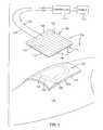
- FIG. 1is an isometric view of a first embodiment of the wound treatment apparatus being applied to a wound on a person's body;
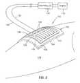
- FIG. 2is an isometric view of the wound treatment apparatus applied to the wound on the person's body
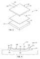
- FIG. 3is an exploded isometric view of the wound treatment apparatus
- FIG. 4is a cross-sectional view of the wound treatment apparatus applied to the wound on the person's body
- FIG. 5is an exploded cross-sectional illustration of an embodiment of the invention above the wound area of the person's body
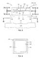
- FIG. 6is a view taken along plane VI—VI of FIG. 5;
- FIG. 7is a view taken along plane VII—VII of FIG. 5;
- FIG. 8is a view taken along plane VIII—VIII of FIG. 5;
- FIG. 9is a view taken along plane IX—IX of FIG. 5;
- FIG. 10is a view taken along plane X—X of FIG. 5;
- FIG. 11is a view taken along plane XI—XI of FIG. 5;
- FIG. 12is a view taken along plane XII—XII of FIG. 5;
- FIG. 13is an exploded cross-sectional view of the first embodiment of the wound treatment apparatus after attaching an attachment device to the heater;
- FIG. 14Ais a planar illustration of an electrical resistance element embedded in a flexible layer for uniform heating
- FIG. 14Bis a view taken along plane XIVB—XIVB of FIG. 14A;
- FIG. 15Ais a planar view of an electrical resistance element embedded in a flexible layer for heating a portion of a treatment area
- FIG. 15Bis a view taken along plane XVB—XVB of FIG. 15A;
- FIG. 16Ais a planar view of an electrical resistance element embedded in a flexible layer for uniform heating of a central portion of a treatment area
- FIG. 16Bis a view taken along plane XVIB—XVIB of FIG. 16A;
- FIG. 17is an exploded cross-sectional view of another embodiment of the invention shown above a wound area
- FIG. 18is a view taken along plane XVIII—XVIII of FIG. 17;
- FIG. 19is a view taken along plane XIX—XIX of FIG. 17;
- FIG. 20is a view taken along plane XX—XX of FIG. 17;
- FIG. 21is a view taken along plane XXI—XXI of FIG. 17;
- FIG. 22is a view taken along plane XXII—XXII of FIG. 17;
- FIG. 23is a view taken along plane XXIII—XXIII of FIG. 17;
- FIG. 24is a view taken along plane XXIV—XXIV of FIG. 17;
- FIG. 25is a view taken along plane XXV—XXV of FIG. 17;
- FIG. 26is a view taken along plane XXVI—XXVI of FIG. 17;
- FIG. 27is a view taken along plane XXVII—XXVII of FIG. 17;
- FIG. 28is a view showing schematically the engagement of the intermittent adhesives shown in FIGS. 26 and 27;
- FIG. 29is an isometric illustration of a further embodiment of the wound treatment apparatus applied to a wound on the person's body;
- FIG. 30is an exploded cross-sectional illustration of the apparatus shown in FIG. 29 shown above the wound;
- FIG. 31is an exploded cross-sectional illustration of the FIG. 29 embodiment with an adhesive attachment device applied to the heater;
- FIG. 32is an isometric illustration of a still another embodiment of the invention applied to a wound on the person's body;
- FIG. 33is an exploded cross-sectional illustration of the FIG. 32 embodiment shown above the wound.
- FIG. 34is an exploded cross-sectional illustration of the FIG. 32 embodiment with an adhesive attachment device applied to the heater.
- FIGS. 1-3wherein like reference numerals designate like or similar parts throughout the several views there are shown various embodiments of a wound treatment apparatus in according to the invention.
- one embodiment of the wound treatment apparatus 100includes a thermally conductive bandage 102 which has first (lower) and second (upper) surfaces 104 and 106 , a heater 108 which has first (lower) and second (upper) surfaces 110 and 112 and an attachment device 114 for joining the heater 108 and the bandage 102 in such a manner as to transfer heat from the heater 108 to the bandage 102 .
- the attachment devicemaintains surface-to-surface contact between the second surface 106 of the bandage 102 and the first surface 110 of the heater.
- the wound treatment apparatus 100is shown in place covering a wound 116 of a person's body 118 , the wound being shown depressed.
- a periwound area 120which is typically a peripheral band of tissue around the wound area with less trauma than the tissue of the wound area.
- the wound treatment apparatusis capable of treating a wound treatment area that includes the wound and/or the periwound area, as desired.
- the second surface 106 of the bandagepreferably comprises a sheet of smooth material.
- this surfacemay be provided by a polymeric film.
- a layer 122 of hydrogel, hydrocolloid, or hydrated alginatemay be affixed to the polymeric film 106 by any suitable means, such as an adhesive, and may provide the first surface 104 . It is preferred that any of these combinations provide the bandage with high thermal conductivity and maintain a moist environment at the wound.
- a foam or gauzemay be used in lieu of the compounds enumerated above. If the gauze or foam provides the first surface 104 , the gauze or foam will absorb moisture from the wound, providing the desired heat conductivity and moist environment.
- the bandage 102may simply be a single layer or film of a heat-conductive polymer so as to optimize heat conductivity of the bandage.
- the bandageit is preferred that the bandage be planar, as shown in FIGS. 3 and 5, and be flexible to conform to the wound 116 as shown in FIG. 4, as well as the person's body, as shown in FIGS. 1 and 2.
- the heater 108includes means for generating heat that may be electrically operated.
- the meansmay take the form of an electrical resistance element 124 which is embedded in or laminated to a flexible planar member 126 , such as polyethylene, silicon, rubber or flexible cloth.
- the heater 108is substantially planar, as shown in FIGS. 1, 3 and 5 , and yet flexible in order that it conform, with the bandage, to the wound 116 , as shown in FIG. 4, and to the person's body as shown in FIGS. 2 and 4.
- the adhesive attachment device 114joins the heater 108 to the bandage 102 , as shown in FIG. 4, so as to maximize heat transfer between the heater 108 and the bandage 102 .
- the electrical resistance element 124is connected to first and second electrical conductors 128 and 130 , which are connected to an electrical power source 132 , via a controller 134 .
- the purpose of the controller 134is to control electrical power provided to the electrical resistance element 124 to maintain a normothermic temperature at or near the wound 116 .
- the electrical resistance element 124may extend back and forth in the flexible planar member 126 with a desired spacing to promote uniform heating of the heater 108 .
- the first surface 104 of the bandage 102is provided with an open pattern of adhesive 136 at or near its periphery.
- the adhesive pattern 136may completely encompass the wound and the periwound area so as to trap the natural moisture of the body which, in turn, moistens the layer 122 of the bandage, or otherwise maintains a moist environment across the wound treatment area for wound therapy purposes.
- the pattern of adhesive 136has inner and outer boundaries 138 and 140 wherein, in the preferred embodiment, the outer boundary 140 coincides with the outer perimeter of the bandage.
- the bandage 102 , the heater 108 , and the pattern of adhesive 136may take various shapes, such as the square, shown in the drawings, or a rectangle, circle or ellipse, or any other regular or irregular shape depending upon various shapes of wound treatment areas.
- the preferred adhesive attachment device 114is a double-sided tape, as shown in FIG. 5 .
- the double-sided tapebe a polymeric film with first and second surfaces with first and second layers of adhesive 142 and 144 thereon.
- the double-sided tapecomes with first and second release liners 146 and 148 which are removed so that the adhesive layers 142 and 144 can be joined to the second surface 106 of the bandage 102 and to the first surface 110 of the heater 108 , respectively, as shown in FIGS. 1, 4 and 5 .
- the release liner 146is partially removed from the adhesive layer 142 (see FIG. 5) in preparation for attaching the heater 108 to the second surface 106 of the bandage 102 .
- the double-sided tape 114is very flexible and conducts heat between the heater 108 and the bandage 102 . It is preferred that the planar dimensions of the double-sided tape 114 be the same as the planar dimension of the heater 108 so as to transfer heat from the entire first surface 110 of the heater 108 to the bandage 102 . It should be noted that, because of the polymeric film 106 forming the second surface of the bandage 102 , transfer of heat by conduction to the bandage 102 is promoted.
- the heater 108When heat therapy is interrupted or terminated, it may be desirable to detach the heater 108 from the bandage 102 .
- the heater 108is preferably detachably joined to the bandage 102 . Detachment in the embodiment just described will necessitate pulling the heater 108 away from the bandage 102 , thereby subjecting each adhesive layer therebelow to a pull force.
- the pull strength of the attachment device 114In order for the bandage 102 to remain in place while the heater 108 is being removed, the pull strength of the attachment device 114 must be less than the pull strength of the pattern of adhesive 136 .
- FIGS. 7-12show the adhesive layers 142 and 144 completely covering the surfaces of the polymeric film.
- the adhesive layer 142has less pull strength than each of the pattern of adhesive 136 and the adhesive layer 144 , allowing the heater 108 to be removed from the bandage 102 without leaving any adhesive on the bandage. This may be accomplished by employing an adhesive layer 142 which is less tacky than each of the pattern of adhesive 136 and the adhesive layer 144 . Less tack can be achieved by doping the same adhesive with a solvent or inert filler, such as talcum or chalk, or employing another adhesive with a tack known to be less than the tack of the adhesives 136 and 144 . If it is desired to leave the adhesive on the bandage 102 , then the roles of the tack would be switched between the adhesive layers 142 and 144 .
- Lower pull strength of the adhesive between the heater 108 and the bandage 102can be provided by intermittent adhesive patterns such as the circular regions 142 i shown in FIG. 9 .
- the adhesive layer 144would be an entire plane so that when the heater is pulled, the double-sided tape leaves with the heater 108 rather than being retained on the bandage 102 .
- the adhesive regions 142 imay be numerous circular dots of adhesive which are sized and spaced from one another in a matrix to provide a pull strength of the adhesive attachment device that is less than the pull strength of the pattern of adhesive 136 and less than continuous adhesive layer 144 .
- the same adhesivemay be used for the adhesive layers 142 and 144 of the double-sided tape and the pattern of adhesive 136 on the bandage.
- the layers 142 and 144 of the double-sided tape 114may be switched if it is desired to leave the double-sided tape on the bandage 102 when the heater 108 is pulled therefrom.
- Another intermittent adhesive patternis shown at 142 s in FIG. 11, wherein diagonal spaced-apart strips of adhesive material are provided across the polymeric film.
- the sizing of the strips and their spacing from one anotherare arranged so that the pull strength of the adhesive attachment device is less than the pull strength of each of the pattern of adhesive 136 and the full plane adhesive layer 144 in FIG. 12 .
- the intermittent adhesive structuremay take various patterns in order to achieve the desired reduction in pull strength.
- the spacing between the intermittent layersshould be made as small as possible so as to promote conductive heat transfer between the heater 108 and the bandage 102 .
- the adhesive layer 142 of the double-sided tapehas been applied to the first surface 110 of the heater 108 and the release liner 146 has been partially removed from the first adhesive layer 142 , similar to the showing in FIG. 1 .
- the heater 108may be supplied with the double-sided tape in place, as shown in FIG. 13, or may be supplied separately as described and shown in FIG. 5 .
- an attachment deviceshould permit the heater and bandage to be joined in such a way as to maximize heat transfer therebetween while permitting the heater to be detached from the bandage without detaching the bandage from the skin. While various adhesive configurations are shown for this purpose, it is contemplated that other attachment mechanisms could be used.
- FIGS. 14-16illustrate various embodiments of electrical resistance heaters 108 . Any of these embodiments are intended to be used in the embodiment of FIGS. 1 and 2.
- the heater 108 a shown in FIG. 14Aand electrical resistance element 124 a winds back and forth within the flexible planar member 126 , similar to what is shown in FIG. 1 .
- the spacing between the windings of the electrical resistance element 124 amay be sized so as to ensure substantially uniform heating.
- FIG. 14Bshows the electrical resistance element embedded or laminated in the flexible planar member 126 . In FIG.
- the electrical resistance element 124 btakes a path along a peripheral zone of the flexible planar member 126 , so that the periphery of the heater 108 b is uniformly heated to a temperature greater than a central portion of the heater. Again, these electrical resistance elements 124 b are shown embedded or laminated in the flexible planar member 126 in FIG. 15 B.
- the electrical resistance element 124 ctakes a spiral path out and back within a central region of the heater 108 c so as to uniformly heat the central region of the heater to a higher temperature than regions outbound therefrom.
- the heater 108 ais adapted for applying heat to both the wound and periwound area 116 and 120 in FIG. 4, the heater 108 b is adapted for applying heat primarily to the periwound area 120 and the heater 108 c is adapted for applying heat primarily to the wound 116 .
- FIG. 17Another embodiment 200 of the wound treatment apparatus is illustrated in FIG. 17, wherein an adhesive layer 202 is on the second surface 106 of the bandage 102 and/or an adhesive layer 204 is on the first surface 110 of the heater 108 .
- FIGS. 18-28Various embodiments of these attachment devices are illustrated in FIGS. 18-28.
- FIGS. 14A through 16BVarious heater embodiments are illustrated in FIGS. 14A through 16B.
- the first embodiment of the attachment deviceis shown in FIGS. 18 and 19, wherein the heater 108 is provided with the adhesive layer 204 and the bandage 102 is not provided with any adhesive layer.
- FIGS. 20 and 21the situation is reversed wherein the bandage 102 is provided with the adhesive layer 202 and the heater 108 does not have an adhesive layer.
- FIGS. 20 and 21the situation is reversed wherein the bandage 102 is provided with the adhesive layer 202 and the heater 108 does not have an adhesive layer.
- FIGS. 20 and 21the situation is reversed wherein the band
- FIGS. 22 and 23illustrate a still further embodiment wherein the bandage 102 is provided with the adhesive layer 202 and the heater 108 is provided with the adhesive layer 204 .
- the adhesive layers 202 and 204 in FIGS. 22 and 23may be made from an adhesive which will bond only when these two adhesive layers are placed in contact with one another. Otherwise, the adhesive layer 204 will not bond to the polymeric surface surrounding the adhesive layer 202 , or any other surface including a person's skin.
- This schemehas an advantage from the standpoint that adhesive layers 202 and 204 on the bandage 102 and the heater 108 , respectively, will not attach to anything until they are brought into contact between the heater 108 and the bandage 102 . This promotes manufacturability, logistics and operation of the invention.
- a suitable adhesive for this purposeis 3 M Non-Tacky Adhesive SJ-3101. It is desirable that the pull strength of the adhesive attachment devices shown in FIGS. 18-23 be lower than the pull strength of the body adhesive 136 shown in FIG. 6 . This can be accomplished by making the tack of the adhesive attachment device less than the tack of the pattern adhesive 136 .
- FIGS. 24-28Attachment devices employing intermittent adhesive patterns are shown in FIGS. 24-28.
- the embodiment in FIGS. 24 and 25shows the heater 108 provided with circular spaced-apart adhesive regions 204 c , while the bandage 102 is not provided with any adhesive.
- each of the bandage 102 and the heater 108is provided with diagonal spaced-apart adhesive strips 202 d and 204 d , respectively. When these adhesive strips are brought into contact with one another, as shown in FIG. 28, they criss-cross one another to provide the desired bonding between the heater 108 and the bandage 102 .
- the adhesive areas of the intermittent adhesive patterns shown in FIGS. 24-28are sized and spaced from one another so that the pull strength of each attachment device is less than the pull strength of the pattern adhesive 136 shown in FIG. 6, as discussed hereinabove. Again, the size of the intermittent adhesive patterns and the spacing therebetween should be tailored to maximize thermal conductivity between the heater 108 and the bandage 102 and yet ensure that the pull strength between the heater and the bandage is less than the pull strength between the bandage and the person's body.
- FIGS. 29-31Another embodiment 300 of the wound treatment apparatus is illustrated in FIGS. 29-31.
- a heater 302employs heated water as the means for generating heat to be provided to the bandage 102 .
- the heater 302may comprise a pouch 304 which has water channels extending back and forth in series from an inlet end 308 to an outlet end 310 .
- the pouch 304may be made by thermo-setting the periphery as well as channel lines of a pair of polymeric films 312 and 314 as shown in FIG. 30 .
- the bottom film 314may be stiffer than the top film 312 .
- Heated wateris supplied by inlet and outlet water lines 316 and 318 which are connected to a water heater 320 via a pump 322 .
- a controller 324is provided for controlling the temperature of the water in the water heater 320 and the amount of water pumped by the pump 322 .
- the heated wateris preferably maintained at such a temperature and flow rate that the wound site 116 is maintained at or near a normothermic temperature.
- the bandage 102may comprise any of the aforementioned embodiments.
- the attachment device for attaching the heater 302 to the bandage 102may comprise any of the aforementioned adhesive attachment devices. or any equivalent devices or arrangements that connect the heater and bandage for maximum thermal conductivity, yet allow detachment of the heater from the bandage without detaching the bandage from a patient's skin.
- the preferred attachment deviceis the double-sided tape 114 shown in FIG. 30, which has been described in detail hereinabove.
- FIG. 31Another suitable attachment device is shown in FIG. 31 wherein the water heater 302 is provided with an adhesive layer 326 and a release liner 328 .
- the release liner 328is simply pulled from the adhesive layer 326 and the adhesive layer 326 is employed for attaching the water heater 302 to the polymeric surface 106 of the bandage 102 .
- FIGS. 32-34Still another embodiment 400 of the wound treatment apparatus is illustrated in FIGS. 32-34.
- a heater 402employs a chemical or phase-change salt as the means for generating heat to be provided to the bandage 102 .
- these materialsare selected to enable the heater 402 to maintain the wound site 116 at or near a normothermic temperature.
- the heater 402may comprise a pair of polymeric films 404 and 406 which are sealed at their peripheries to provide an enclosure for the chemical or phase change salt.
- the polymeric films 404 and 406may be joined by spot thermo-setting at spaced-apart locations 408 for the purpose of lowering the profile of the heater and maintaining the chemical or phase-change salt in discrete confined areas.
- the film 406may be stiffer than the film 404 .
- the bandage 102 and the attachment device for attaching the heater 402 to the bandage 102may be any of the embodiments described hereinabove.
- the preferred attachment deviceis the double-sided tape 114 , as shown in FIG. 33, which is filly described hereinabove.
- the heater 402may be provided with an adhesive layer 410 which is covered by a release liner 412 , as shown in FIG. 34 .
- the inventionprovides a wound treatment device having a low profile for the convenience of the patient and permitting easy removal of the heater from a bandage without disturbing the attachment of the bandage to the person's body.
- the bandage, the heater and the attachment deviceare all flexible and cooperate to conform to the wound to the contour of a person's body where the wound is located so as to permit a substantially hermetic seal about, and moist environment at, the wound site.
- Numerous attachment embodimentshave been described for making the pull strength between the heater 108 and the bandage 102 less than the pull strength between the bandage 102 and the person's body. Even though the bandage 102 is removable, it is desirable to first remove the heater and then to take special care in removing the bandage from the person's body.
- the inventionalso enables treatment of the wound and/or the periwound, as desired.
- the heater embodimentsall enable a wound treatment device according to this invention to maintain the temperature of a wound site at or near a normothermic level. That is to say, the wound treatment device maintains the temperature of tissue in and/or near a wound in a range of about 36° C. to about 38° C.
Landscapes
- Health & Medical Sciences (AREA)
- Life Sciences & Earth Sciences (AREA)
- Engineering & Computer Science (AREA)
- Biomedical Technology (AREA)
- Heart & Thoracic Surgery (AREA)
- Vascular Medicine (AREA)
- Animal Behavior & Ethology (AREA)
- General Health & Medical Sciences (AREA)
- Public Health (AREA)
- Veterinary Medicine (AREA)
- Dermatology (AREA)
- Chemical & Material Sciences (AREA)
- Dispersion Chemistry (AREA)
- Thermotherapy And Cooling Therapy Devices (AREA)
Abstract
Description
Claims (49)
Priority Applications (1)
| Application Number | Priority Date | Filing Date | Title |
|---|---|---|---|
| US10/196,875US6585670B2 (en) | 1998-04-06 | 2002-07-15 | Treatment apparatus with a heater adhesively joined to a bandage |
Applications Claiming Priority (3)
| Application Number | Priority Date | Filing Date | Title |
|---|---|---|---|
| US09/055,597US6071304A (en) | 1998-04-06 | 1998-04-06 | Wound treatment apparatus with a heater adhesively joined to a bandage |
| US09/493,546US6436063B1 (en) | 1998-04-06 | 2000-01-28 | Wound treatment apparatus with a heater adhesively joined to bandage |
| US10/196,875US6585670B2 (en) | 1998-04-06 | 2002-07-15 | Treatment apparatus with a heater adhesively joined to a bandage |
Related Parent Applications (1)
| Application Number | Title | Priority Date | Filing Date |
|---|---|---|---|
| US09/493,546ContinuationUS6436063B1 (en) | 1998-04-06 | 2000-01-28 | Wound treatment apparatus with a heater adhesively joined to bandage |
Publications (2)
| Publication Number | Publication Date |
|---|---|
| US20020183813A1 US20020183813A1 (en) | 2002-12-05 |
| US6585670B2true US6585670B2 (en) | 2003-07-01 |
Family
ID=21998926
Family Applications (3)
| Application Number | Title | Priority Date | Filing Date |
|---|---|---|---|
| US09/055,597Expired - Fee RelatedUS6071304A (en) | 1998-04-06 | 1998-04-06 | Wound treatment apparatus with a heater adhesively joined to a bandage |
| US09/493,546Expired - LifetimeUS6436063B1 (en) | 1998-04-06 | 2000-01-28 | Wound treatment apparatus with a heater adhesively joined to bandage |
| US10/196,875Expired - LifetimeUS6585670B2 (en) | 1998-04-06 | 2002-07-15 | Treatment apparatus with a heater adhesively joined to a bandage |
Family Applications Before (2)
| Application Number | Title | Priority Date | Filing Date |
|---|---|---|---|
| US09/055,597Expired - Fee RelatedUS6071304A (en) | 1998-04-06 | 1998-04-06 | Wound treatment apparatus with a heater adhesively joined to a bandage |
| US09/493,546Expired - LifetimeUS6436063B1 (en) | 1998-04-06 | 2000-01-28 | Wound treatment apparatus with a heater adhesively joined to bandage |
Country Status (1)
| Country | Link |
|---|---|
| US (3) | US6071304A (en) |
Cited By (15)
| Publication number | Priority date | Publication date | Assignee | Title |
|---|---|---|---|---|
| US20050096574A1 (en)* | 2003-10-31 | 2005-05-05 | Wibaux Anne M.P. | Skin-contacting heatable dressing |
| US20060235347A1 (en)* | 2005-04-16 | 2006-10-19 | Adel Aali | Deformable and conformable wound protecting apparatus and its method of application |
| US20070027481A1 (en)* | 2005-07-28 | 2007-02-01 | Weinfield Todd A | Apparatus and Method for Treatment of Infected Nail |
| US20070142761A1 (en)* | 2005-12-15 | 2007-06-21 | Adel Aali | Wound shield |
| US20070142757A1 (en)* | 2005-12-15 | 2007-06-21 | Adel Aali | Wound shield and warming apparatus and method |
| US20070161938A1 (en)* | 2006-01-12 | 2007-07-12 | Adel Aali | Dressing substrate |
| US20070191754A1 (en)* | 2006-02-13 | 2007-08-16 | Adel Aali | Wound shield |
| US20100036475A1 (en)* | 2006-04-27 | 2010-02-11 | Wilifrido Castaneda | Methods and apparatus for extraluminal femoropopliteal bypass graft |
| US20100100090A1 (en)* | 2008-10-17 | 2010-04-22 | Medicold Limited | Thermotherapy application and control system |
| US20100312159A1 (en)* | 2005-04-16 | 2010-12-09 | Adel Aali | Secondary Wound Dressings for Securing Primary Dressings and Managing Fluid from Wounds, and Methods of Using Same |
| US20110015557A1 (en)* | 2009-07-16 | 2011-01-20 | Aalnex, Inc. | Systems And Methods For Protecting Incisions |
| US8067662B2 (en) | 2009-04-01 | 2011-11-29 | Aalnex, Inc. | Systems and methods for wound protection and exudate management |
| US8281699B2 (en) | 2002-06-07 | 2012-10-09 | Kriss Systems Sa | Firearm with enhanced recoil and control characteristics |
| US9217614B2 (en)* | 2011-02-11 | 2015-12-22 | Jorge Pizano | Firearm having an articulated bolt train with transversally displacing firing mechanism, delay blowback breech opening, and recoil damper |
| US9937072B2 (en) | 2007-12-07 | 2018-04-10 | Carewave Medical, Inc. | Devices and methods for therapeutic heat treatment |
Families Citing this family (53)
| Publication number | Priority date | Publication date | Assignee | Title |
|---|---|---|---|---|
| US7928281B2 (en) | 1992-06-19 | 2011-04-19 | Arizant Technologies Llc | Wound covering |
| US6071304A (en)* | 1998-04-06 | 2000-06-06 | Augustine Medical, Inc. | Wound treatment apparatus with a heater adhesively joined to a bandage |
| US6458109B1 (en) | 1998-08-07 | 2002-10-01 | Hill-Rom Services, Inc. | Wound treatment apparatus |
| US6548728B1 (en)* | 1999-08-11 | 2003-04-15 | Medical Products, Inc. | Wound dressing garment |
| US7744640B1 (en) | 1999-08-11 | 2010-06-29 | Medical Products, Inc. | Thermal treatment garment and method of thermally treating body portions |
| JP4681185B2 (en) | 1999-11-29 | 2011-05-11 | ケーシーアイ メディカル リソーシーズ | Trauma treatment device |
| US6824533B2 (en) | 2000-11-29 | 2004-11-30 | Hill-Rom Services, Inc. | Wound treatment apparatus |
| US6764462B2 (en) | 2000-11-29 | 2004-07-20 | Hill-Rom Services Inc. | Wound treatment apparatus |
| US20010043943A1 (en) | 2000-05-22 | 2001-11-22 | Coffey Arthur C. | Combination SIS and vacuum bandage and method |
| US7662169B2 (en)* | 2000-09-05 | 2010-02-16 | Wittmann Dietmar H | Prosthesis and method for lowering abdominal pressure |
| US6855135B2 (en)* | 2000-11-29 | 2005-02-15 | Hill-Rom Services, Inc. | Vacuum therapy and cleansing dressing for wounds |
| US6685681B2 (en) | 2000-11-29 | 2004-02-03 | Hill-Rom Services, Inc. | Vacuum therapy and cleansing dressing for wounds |
| JP2004534595A (en) | 2001-07-12 | 2004-11-18 | ヒル−ロム サービシズ,インコーポレイテッド | Control of vacuum rate of change |
| US7658749B2 (en)* | 2001-09-05 | 2010-02-09 | Wittmann Dietmar H | Method for creating a temporary hypobaric wound space in an intentionally left open surgical wound to diagnose substrate losses and prevent exogenous contamination with microorganisms |
| WO2003030966A1 (en) | 2001-10-11 | 2003-04-17 | Hill-Rom Services, Inc. | Waste container for negative pressure therapy |
| GB0126614D0 (en)* | 2001-11-06 | 2002-01-02 | Gorix Ltd | Heated wound dressing |
| US6699266B2 (en) | 2001-12-08 | 2004-03-02 | Charles A. Lachenbruch | Support surface with phase change material or heat tubes |
| US7083839B2 (en)* | 2001-12-20 | 2006-08-01 | Kimberly-Clark Worldwide, Inc. | Laminate structures containing activatable materials |
| AU2002359828A1 (en) | 2001-12-26 | 2003-07-24 | Hill-Rom Services Inc. | Vented vacuum bandage and method |
| AU2002359829A1 (en) | 2001-12-26 | 2003-07-24 | Hill-Rom Services, Inc. | Vacuum bandage packing |
| EP1461113A4 (en) | 2001-12-26 | 2009-05-06 | Hill Rom Services Inc | Wound vacuum therapy dressing kit |
| EP1487389B1 (en) | 2002-02-28 | 2011-10-05 | KCI Medical Resources | External catheter access to vacuum bandage |
| US8168848B2 (en) | 2002-04-10 | 2012-05-01 | KCI Medical Resources, Inc. | Access openings in vacuum bandage |
| JP2005536275A (en) | 2002-08-21 | 2005-12-02 | ヒル−ロム サービシズ,インコーポレイテッド | Wound packing to prevent wound closure |
| US6772825B2 (en) | 2002-11-04 | 2004-08-10 | Charles A. Lachenbruch | Heat exchange support surface |
| GB0312550D0 (en)* | 2003-06-02 | 2003-07-09 | Nel Technologies Ltd | Functional insole heater for footwear |
| GB0312553D0 (en)* | 2003-06-02 | 2003-07-09 | Nel Technologies Ltd | Functional heater for formed components |
| GB0312552D0 (en)* | 2003-06-02 | 2003-07-09 | Nel Technologies Ltd | Functional therapeutic corporeal and wound dressing heaters |
| GB0312551D0 (en)* | 2003-06-02 | 2003-07-09 | Nel Technologies Ltd | Functional electro-conductive garments |
| US7328370B2 (en)* | 2003-09-12 | 2008-02-05 | Rockwell Automation Technologies, Inc. | Safety controller with simplified interface |
| US8109981B2 (en) | 2005-01-25 | 2012-02-07 | Valam Corporation | Optical therapies and devices |
| WO2006086513A2 (en)* | 2005-02-08 | 2006-08-17 | Carewave, Inc. | Apparatus and method for using a portable thermal device to reduce accommodation of nerve receptors |
| US7763060B2 (en)* | 2006-02-22 | 2010-07-27 | Baumann Nicholas R | Patient warming drape |
| US7931651B2 (en) | 2006-11-17 | 2011-04-26 | Wake Lake University Health Sciences | External fixation assembly and method of use |
| US8377016B2 (en) | 2007-01-10 | 2013-02-19 | Wake Forest University Health Sciences | Apparatus and method for wound treatment employing periodic sub-atmospheric pressure |
| KR101600041B1 (en) | 2007-10-10 | 2016-03-03 | 웨이크 포리스트 유니버시티 헬스 사이언시즈 | Devices and methods for treating spinal cord tissue |
| RU2517588C2 (en) | 2008-01-09 | 2014-05-27 | Уэйк Форест Юниверсити Хелс Сайенсиз | Device and method for treating pathologies of central nervous system |
| ES2633142T3 (en) | 2008-07-18 | 2017-09-19 | Wake Forest University Health Sciences | Apparatus for modulation of cardiac tissue through topical application of vacuum to minimize death and cell damage |
| JP5933223B2 (en)* | 2010-11-12 | 2016-06-08 | 国立研究開発法人農業生物資源研究所 | Cell culture chamber and manufacturing method thereof, and tissue model using the cell culture chamber and manufacturing method thereof |
| US10603208B2 (en) | 2011-01-21 | 2020-03-31 | Carewave Medical, Inc. | Modular stimulus applicator system and method |
| JP5877660B2 (en)* | 2011-06-28 | 2016-03-08 | 桐灰化学株式会社 | Heating tool |
| US10123801B2 (en)* | 2011-11-01 | 2018-11-13 | Zipline Medical, Inc. | Means to prevent wound dressings from adhering to closure device |
| AU2012340381B2 (en) | 2011-11-15 | 2017-04-06 | Solventum Intellectual Properties Company | Medical dressings, systems, and methods with thermally- enhanced vapor transmission |
| WO2014180975A1 (en) | 2013-05-10 | 2014-11-13 | Kirwan Laurence | Normothermic maintenance method and system |
| JP2017512620A (en) | 2014-03-28 | 2017-05-25 | スリーエム イノベイティブ プロパティズ カンパニー | Articles and methods for negative pressure wound closure therapy |
| CN107530198A (en)* | 2015-04-08 | 2018-01-02 | Lts勒曼治疗系统股份公司 | Electric patch |
| US11559421B2 (en) | 2015-06-25 | 2023-01-24 | Hill-Rom Services, Inc. | Protective dressing with reusable phase-change material cooling insert |
| US10583228B2 (en) | 2015-07-28 | 2020-03-10 | J&M Shuler Medical, Inc. | Sub-atmospheric wound therapy systems and methods |
| US11583437B2 (en) | 2018-02-06 | 2023-02-21 | Aspen Surgical Products, Inc. | Reusable warming blanket with phase change material |
| JP2021517024A (en) | 2018-03-07 | 2021-07-15 | ソーヴ ラボズ インコーポレイテッド | Systems and methods for improved pain relief from heat fiber stimulation |
| US11160917B2 (en) | 2020-01-22 | 2021-11-02 | J&M Shuler Medical Inc. | Negative pressure wound therapy barrier |
| US11723810B2 (en)* | 2020-05-14 | 2023-08-15 | Jason Fladoos | Modular physio tape with thermal properties |
| EP4545056A3 (en)* | 2020-09-28 | 2025-07-16 | Coloplast A/S | Medical appliance |
Citations (13)
| Publication number | Priority date | Publication date | Assignee | Title |
|---|---|---|---|---|
| WO1994000009A1 (en) | 1992-06-19 | 1994-01-06 | Nonomura Arthur M | Methods and compositions for enhancing carbon fixation in plants |
| US5662624A (en) | 1992-03-27 | 1997-09-02 | Coloplast A/S | Heat dressing comprising a heat generating unit and an adhesive layer |
| US5817145A (en) | 1994-11-21 | 1998-10-06 | Augustine Medical, Inc. | Wound treatment device |
| US5954680A (en) | 1992-06-19 | 1999-09-21 | Augustine Medical, Inc. | Near hyperthermic heater wound covering |
| US5964723A (en) | 1992-06-19 | 1999-10-12 | Augustine Medical, Inc. | Normothermic tissue heating wound covering |
| US5986163A (en) | 1992-06-19 | 1999-11-16 | Augustine Medical, Inc. | Normothermic heater wound covering |
| US6071304A (en)* | 1998-04-06 | 2000-06-06 | Augustine Medical, Inc. | Wound treatment apparatus with a heater adhesively joined to a bandage |
| US6080189A (en) | 1998-04-06 | 2000-06-27 | Augustine Medical, Inc. | Wound treatment apparatus including a heater and an IR-Transparent or IR-Transmissive bandage |
| US6093160A (en) | 1994-11-21 | 2000-07-25 | Augustine Medical, Inc. | Flexible non-contact wound treatment device |
| US6095992A (en) | 1998-04-06 | 2000-08-01 | Augustine Medical, Inc. | Wound treatment apparatus for normothermic treatment of wounds |
| US6110197A (en) | 1994-11-21 | 2000-08-29 | Augustine Medical, Inc. | Flexible non-contact wound treatment device with a single joint |
| US6213965B1 (en) | 1998-04-06 | 2001-04-10 | Augustine Medical, Inc. | Wound treatment apparatus with infrared absorptive wound cover |
| US6235047B1 (en) | 1998-04-06 | 2001-05-22 | Augustine Medical, Inc. | Wound treatment apparatus with a heater, a heat conductive bandage, and heat-spreading means acting between the heater and bandage |
Family Cites Families (1)
| Publication number | Priority date | Publication date | Assignee | Title |
|---|---|---|---|---|
| DE69323080T2 (en)* | 1992-06-19 | 1999-05-27 | Scott D. Bloomington Minn. Augustine | Wound cover |
- 1998
- 1998-04-06USUS09/055,597patent/US6071304A/ennot_activeExpired - Fee Related
- 2000
- 2000-01-28USUS09/493,546patent/US6436063B1/ennot_activeExpired - Lifetime
- 2002
- 2002-07-15USUS10/196,875patent/US6585670B2/ennot_activeExpired - Lifetime
Patent Citations (14)
| Publication number | Priority date | Publication date | Assignee | Title |
|---|---|---|---|---|
| US5662624A (en) | 1992-03-27 | 1997-09-02 | Coloplast A/S | Heat dressing comprising a heat generating unit and an adhesive layer |
| US5954680A (en) | 1992-06-19 | 1999-09-21 | Augustine Medical, Inc. | Near hyperthermic heater wound covering |
| US5964723A (en) | 1992-06-19 | 1999-10-12 | Augustine Medical, Inc. | Normothermic tissue heating wound covering |
| US5986163A (en) | 1992-06-19 | 1999-11-16 | Augustine Medical, Inc. | Normothermic heater wound covering |
| WO1994000009A1 (en) | 1992-06-19 | 1994-01-06 | Nonomura Arthur M | Methods and compositions for enhancing carbon fixation in plants |
| US6093160A (en) | 1994-11-21 | 2000-07-25 | Augustine Medical, Inc. | Flexible non-contact wound treatment device |
| US5817145A (en) | 1994-11-21 | 1998-10-06 | Augustine Medical, Inc. | Wound treatment device |
| US6110197A (en) | 1994-11-21 | 2000-08-29 | Augustine Medical, Inc. | Flexible non-contact wound treatment device with a single joint |
| US6071304A (en)* | 1998-04-06 | 2000-06-06 | Augustine Medical, Inc. | Wound treatment apparatus with a heater adhesively joined to a bandage |
| US6095992A (en) | 1998-04-06 | 2000-08-01 | Augustine Medical, Inc. | Wound treatment apparatus for normothermic treatment of wounds |
| US6080189A (en) | 1998-04-06 | 2000-06-27 | Augustine Medical, Inc. | Wound treatment apparatus including a heater and an IR-Transparent or IR-Transmissive bandage |
| US6213965B1 (en) | 1998-04-06 | 2001-04-10 | Augustine Medical, Inc. | Wound treatment apparatus with infrared absorptive wound cover |
| US6235047B1 (en) | 1998-04-06 | 2001-05-22 | Augustine Medical, Inc. | Wound treatment apparatus with a heater, a heat conductive bandage, and heat-spreading means acting between the heater and bandage |
| US6436063B1 (en)* | 1998-04-06 | 2002-08-20 | Augustine Medical, Inc. | Wound treatment apparatus with a heater adhesively joined to bandage |
Cited By (32)
| Publication number | Priority date | Publication date | Assignee | Title |
|---|---|---|---|---|
| US8281699B2 (en) | 2002-06-07 | 2012-10-09 | Kriss Systems Sa | Firearm with enhanced recoil and control characteristics |
| US7238196B2 (en) | 2003-10-31 | 2007-07-03 | Avery Dennison Corporation | Skin-contacting heatable dressing |
| US20050096574A1 (en)* | 2003-10-31 | 2005-05-05 | Wibaux Anne M.P. | Skin-contacting heatable dressing |
| US7745683B2 (en) | 2005-04-16 | 2010-06-29 | Aalnex, Inc. | Deformable and conformable wound protecting apparatus and its method of application |
| US20060235347A1 (en)* | 2005-04-16 | 2006-10-19 | Adel Aali | Deformable and conformable wound protecting apparatus and its method of application |
| US8415523B2 (en) | 2005-04-16 | 2013-04-09 | Aalnex, Inc. | Secondary wound dressings for securing primary dressings and managing fluid from wounds, and methods of using same |
| US20100312159A1 (en)* | 2005-04-16 | 2010-12-09 | Adel Aali | Secondary Wound Dressings for Securing Primary Dressings and Managing Fluid from Wounds, and Methods of Using Same |
| US20070027481A1 (en)* | 2005-07-28 | 2007-02-01 | Weinfield Todd A | Apparatus and Method for Treatment of Infected Nail |
| US7793666B2 (en) | 2005-07-28 | 2010-09-14 | Innovation Biomedical Devices, Inc. | Apparatus and method for treatment of infected nail |
| US7601129B2 (en) | 2005-12-15 | 2009-10-13 | Aalnex, Inc. | Wound shield and warming apparatus and method |
| US20070142757A1 (en)* | 2005-12-15 | 2007-06-21 | Adel Aali | Wound shield and warming apparatus and method |
| US8586818B2 (en) | 2005-12-15 | 2013-11-19 | Aalnex, Inc. | Wound shield |
| US20100004611A1 (en)* | 2005-12-15 | 2010-01-07 | Adel Aali | Wound Shield With Enclosed Vacuum Space |
| US8558050B2 (en) | 2005-12-15 | 2013-10-15 | Aalnex, Inc. | Wound shield with enclosed vacuum space |
| US20070142761A1 (en)* | 2005-12-15 | 2007-06-21 | Adel Aali | Wound shield |
| US8362315B2 (en) | 2005-12-15 | 2013-01-29 | Aalnex, Inc. | Dressing substrate |
| US20070161938A1 (en)* | 2006-01-12 | 2007-07-12 | Adel Aali | Dressing substrate |
| US7863495B2 (en) | 2006-01-12 | 2011-01-04 | Aalnex, Inc. | Dressing substrate |
| US7816577B2 (en) | 2006-02-13 | 2010-10-19 | Aalnex, Inc. | Wound shield |
| US20110034888A1 (en)* | 2006-02-13 | 2011-02-10 | Aalnex, Inc. | Wound shield |
| US8669408B2 (en) | 2006-02-13 | 2014-03-11 | Aalnex, Inc. | Wound shield |
| US8227657B2 (en) | 2006-02-13 | 2012-07-24 | Aalnex, Inc. | Wound shield |
| US20070191754A1 (en)* | 2006-02-13 | 2007-08-16 | Adel Aali | Wound shield |
| US20100036475A1 (en)* | 2006-04-27 | 2010-02-11 | Wilifrido Castaneda | Methods and apparatus for extraluminal femoropopliteal bypass graft |
| US9937072B2 (en) | 2007-12-07 | 2018-04-10 | Carewave Medical, Inc. | Devices and methods for therapeutic heat treatment |
| US20100100090A1 (en)* | 2008-10-17 | 2010-04-22 | Medicold Limited | Thermotherapy application and control system |
| US9545286B2 (en) | 2008-10-17 | 2017-01-17 | Medicold Limited | Thermotherapy application and control system |
| US8067662B2 (en) | 2009-04-01 | 2011-11-29 | Aalnex, Inc. | Systems and methods for wound protection and exudate management |
| US8722960B2 (en) | 2009-04-01 | 2014-05-13 | Aalnex, Inc. | Systems and methods for wound protection and exudate management |
| US20110015557A1 (en)* | 2009-07-16 | 2011-01-20 | Aalnex, Inc. | Systems And Methods For Protecting Incisions |
| US8252971B2 (en) | 2009-07-16 | 2012-08-28 | Aalnex, Inc. | Systems and methods for protecting incisions |
| US9217614B2 (en)* | 2011-02-11 | 2015-12-22 | Jorge Pizano | Firearm having an articulated bolt train with transversally displacing firing mechanism, delay blowback breech opening, and recoil damper |
Also Published As
| Publication number | Publication date |
|---|---|
| US6436063B1 (en) | 2002-08-20 |
| US6071304A (en) | 2000-06-06 |
| US20020183813A1 (en) | 2002-12-05 |
Similar Documents
| Publication | Publication Date | Title |
|---|---|---|
| US6585670B2 (en) | Treatment apparatus with a heater adhesively joined to a bandage | |
| US6641601B1 (en) | Tissue treatment apparatus with a heater, a heat conductive bandage, and a heat-spreading means acting between the heater and bandage | |
| US6589270B2 (en) | Normothermic treatment apparatus with chemical, phase-change, or hot water means for heating | |
| US6080189A (en) | Wound treatment apparatus including a heater and an IR-Transparent or IR-Transmissive bandage | |
| US6254557B1 (en) | Wound treatment apparatus with infrared absorptive wound cover | |
| US6264622B1 (en) | Normothermic heater wound covering | |
| US6423018B1 (en) | Normothermic tissue heating wound covering | |
| US6569189B1 (en) | Tissue treatment apparatus including a bandpass filter transparent to selected wavelengths of IR electromagnetic spectrum | |
| US6407307B1 (en) | Near hyperthermic heater covering | |
| US6840915B2 (en) | Normothermic tissue treatment | |
| HK1024400A (en) | Normothermic heater wound covering |
Legal Events
| Date | Code | Title | Description |
|---|---|---|---|
| STCF | Information on status: patent grant | Free format text:PATENTED CASE | |
| AS | Assignment | Owner name:ARIZANT TECHNOLOGIES LLC, MINNESOTA Free format text:ASSIGNMENT OF ASSIGNORS INTEREST;ASSIGNOR:AUGUSTINE MEDICAL, INC.;REEL/FRAME:015711/0304 Effective date:20040506 Owner name:ARIZANT TECHNOLOGIES LLC,MINNESOTA Free format text:ASSIGNMENT OF ASSIGNORS INTEREST;ASSIGNOR:AUGUSTINE MEDICAL, INC.;REEL/FRAME:015711/0304 Effective date:20040506 | |
| AS | Assignment | Owner name:MERRILL LYNCH CAPITAL, A DIVISION OF MERRILL LYNCH Free format text:SECURITY INTEREST;ASSIGNOR:ARIZANT TECHNOLOGIES LLC;REEL/FRAME:015661/0166 Effective date:20040730 | |
| FPAY | Fee payment | Year of fee payment:4 | |
| CC | Certificate of correction | ||
| AS | Assignment | Owner name:GENERAL ELECTRIC CAPITAL CORPORATION, AS ADMINISTR Free format text:SECURITY AGREEMENT;ASSIGNOR:ARIZANT TECHNOLOGIES LLC;REEL/FRAME:022813/0141 Effective date:20090611 | |
| AS | Assignment | Owner name:ARIZANT TECHNOLOGIES LLC, MINNESOTA Free format text:RELEASE BY SECURED PARTY;ASSIGNOR:GE BUSINESS FINANCIAL SERVICES INC. (F/K/A MERRILL LYNCH BUSINESS FINANCIAL SERVICES INC.), AS ADMINISTRATIVE AGENT;REEL/FRAME:022813/0393 Effective date:20090611 Owner name:ARIZANT TECHNOLOGIES LLC,MINNESOTA Free format text:RELEASE BY SECURED PARTY;ASSIGNOR:GE BUSINESS FINANCIAL SERVICES INC. (F/K/A MERRILL LYNCH BUSINESS FINANCIAL SERVICES INC.), AS ADMINISTRATIVE AGENT;REEL/FRAME:022813/0393 Effective date:20090611 | |
| FEPP | Fee payment procedure | Free format text:PAT HOLDER NO LONGER CLAIMS SMALL ENTITY STATUS, ENTITY STATUS SET TO UNDISCOUNTED (ORIGINAL EVENT CODE: STOL); ENTITY STATUS OF PATENT OWNER: LARGE ENTITY | |
| AS | Assignment | Owner name:GENERAL ELECTRIC CAPITAL CORPORATION, MARYLAND Free format text:ASSIGNMENT OF ASSIGNORS INTEREST;ASSIGNOR:ARIZANT TECHNOLOGIES LLC;REEL/FRAME:025137/0056 Effective date:20101013 | |
| AS | Assignment | Owner name:ARIZANT TECHNOLOGIES LLC, MINNESOTA Free format text:CORRECTIVE ASSIGNMENT TO CORRECT THE NATURE OF THE CONVEYANCE AS A RELEASE BY SECURED PARTY, AND THE IDENTITY OF THE ASSIGNOR AND ASSIGNEE PREVIOUSLY RECORDED ON REEL 025137 FRAME 0056. ASSIGNOR(S) HEREBY CONFIRMS THE RELEASE OF SECURITY INTEREST IN ALL OF GRANTOR'S RIGHT, TITLE AND INTEREST IN PATENT RIGHTS.;ASSIGNOR:GENERAL ELECTRIC CAPITAL CORPORATION, AS ADMINISTRATIVE AGENT;REEL/FRAME:025444/0913 Effective date:20101013 | |
| FPAY | Fee payment | Year of fee payment:8 | |
| AS | Assignment | Owner name:3M INNOVATIVE PROPERTIES COMPANY, MINNESOTA Free format text:ASSIGNMENT OF ASSIGNORS INTEREST;ASSIGNOR:ARIZANT TECHNOLOGIES LLC;REEL/FRAME:031980/0486 Effective date:20131212 | |
| FPAY | Fee payment | Year of fee payment:12 |