US6585597B2 - Impulse radio interactive wireless gaming system, gaming unit, game server and method - Google Patents
Impulse radio interactive wireless gaming system, gaming unit, game server and methodDownload PDFInfo
- Publication number
- US6585597B2 US6585597B2US09/873,747US87374701AUS6585597B2US 6585597 B2US6585597 B2US 6585597B2US 87374701 AUS87374701 AUS 87374701AUS 6585597 B2US6585597 B2US 6585597B2
- Authority
- US
- United States
- Prior art keywords
- impulse radio
- gaming
- game server
- gaming unit
- signal
- Prior art date
- Legal status (The legal status is an assumption and is not a legal conclusion. Google has not performed a legal analysis and makes no representation as to the accuracy of the status listed.)
- Expired - Fee Related
Links
- 230000002452interceptive effectEffects0.000titleclaimsabstractdescription40
- 238000000034methodMethods0.000titleclaimsdescription90
- 238000012512characterization methodMethods0.000claimsdescription15
- 238000005516engineering processMethods0.000abstractdescription13
- 230000006872improvementEffects0.000abstractdescription6
- 238000004891communicationMethods0.000description31
- 238000001228spectrumMethods0.000description15
- 230000000737periodic effectEffects0.000description11
- 238000013459approachMethods0.000description10
- 230000005540biological transmissionEffects0.000description10
- 230000004044responseEffects0.000description10
- 230000003595spectral effectEffects0.000description10
- 230000002123temporal effectEffects0.000description10
- 230000003111delayed effectEffects0.000description9
- 230000008569processEffects0.000description9
- 238000010586diagramMethods0.000description8
- 238000012545processingMethods0.000description8
- 230000006870functionEffects0.000description7
- 230000008901benefitEffects0.000description6
- 238000001514detection methodMethods0.000description6
- 238000013507mappingMethods0.000description6
- 238000005259measurementMethods0.000description6
- 238000005070samplingMethods0.000description5
- 238000012546transferMethods0.000description5
- 230000000694effectsEffects0.000description4
- 230000000116mitigating effectEffects0.000description4
- 230000009471actionEffects0.000description3
- 238000009826distributionMethods0.000description3
- 238000005562fadingMethods0.000description3
- 238000009499grossingMethods0.000description3
- 230000001976improved effectEffects0.000description3
- 238000012986modificationMethods0.000description3
- 230000004048modificationEffects0.000description3
- 230000011664signalingEffects0.000description3
- 230000001360synchronised effectEffects0.000description3
- 230000000739chaotic effectEffects0.000description2
- 238000006243chemical reactionMethods0.000description2
- 230000008878couplingEffects0.000description2
- 238000010168coupling processMethods0.000description2
- 238000005859coupling reactionMethods0.000description2
- 230000001934delayEffects0.000description2
- 238000013461designMethods0.000description2
- 238000001914filtrationMethods0.000description2
- 230000010354integrationEffects0.000description2
- 238000013178mathematical modelMethods0.000description2
- 239000002184metalSubstances0.000description2
- 230000000644propagated effectEffects0.000description2
- 238000007493shaping processMethods0.000description2
- 230000007480spreadingEffects0.000description2
- 238000003892spreadingMethods0.000description2
- 230000001960triggered effectEffects0.000description2
- 230000000007visual effectEffects0.000description2
- 238000012935AveragingMethods0.000description1
- 239000000654additiveSubstances0.000description1
- 230000000996additive effectEffects0.000description1
- 230000002411adverseEffects0.000description1
- 230000004075alterationEffects0.000description1
- 238000004458analytical methodMethods0.000description1
- 230000006399behaviorEffects0.000description1
- 230000009286beneficial effectEffects0.000description1
- 230000000903blocking effectEffects0.000description1
- 239000003990capacitorSubstances0.000description1
- 230000008859changeEffects0.000description1
- 239000002131composite materialSubstances0.000description1
- 238000005314correlation functionMethods0.000description1
- 230000001419dependent effectEffects0.000description1
- 238000004880explosionMethods0.000description1
- 230000036039immunityEffects0.000description1
- 230000036540impulse transmissionEffects0.000description1
- 230000000977initiatory effectEffects0.000description1
- 230000007246mechanismEffects0.000description1
- 239000000203mixtureSubstances0.000description1
- 238000009304pastoral farmingMethods0.000description1
- 238000002360preparation methodMethods0.000description1
- 230000001902propagating effectEffects0.000description1
- 230000002441reversible effectEffects0.000description1
- 238000012552reviewMethods0.000description1
- 238000000926separation methodMethods0.000description1
- 238000003860storageMethods0.000description1
- 230000001755vocal effectEffects0.000description1
Images


Classifications
- A—HUMAN NECESSITIES
- A63—SPORTS; GAMES; AMUSEMENTS
- A63F—CARD, BOARD, OR ROULETTE GAMES; INDOOR GAMES USING SMALL MOVING PLAYING BODIES; VIDEO GAMES; GAMES NOT OTHERWISE PROVIDED FOR
- A63F13/00—Video games, i.e. games using an electronically generated display having two or more dimensions
- A63F13/30—Interconnection arrangements between game servers and game devices; Interconnection arrangements between game devices; Interconnection arrangements between game servers
- A63F13/32—Interconnection arrangements between game servers and game devices; Interconnection arrangements between game devices; Interconnection arrangements between game servers using local area network [LAN] connections
- A63F13/327—Interconnection arrangements between game servers and game devices; Interconnection arrangements between game devices; Interconnection arrangements between game servers using local area network [LAN] connections using wireless networks, e.g. Wi-Fi® or piconet
- A63F13/12—
- A—HUMAN NECESSITIES
- A63—SPORTS; GAMES; AMUSEMENTS
- A63F—CARD, BOARD, OR ROULETTE GAMES; INDOOR GAMES USING SMALL MOVING PLAYING BODIES; VIDEO GAMES; GAMES NOT OTHERWISE PROVIDED FOR
- A63F13/00—Video games, i.e. games using an electronically generated display having two or more dimensions
- A63F13/30—Interconnection arrangements between game servers and game devices; Interconnection arrangements between game devices; Interconnection arrangements between game servers
- A63F13/35—Details of game servers
- A63F13/358—Adapting the game course according to the network or server load, e.g. for reducing latency due to different connection speeds between clients
- A—HUMAN NECESSITIES
- A63—SPORTS; GAMES; AMUSEMENTS
- A63F—CARD, BOARD, OR ROULETTE GAMES; INDOOR GAMES USING SMALL MOVING PLAYING BODIES; VIDEO GAMES; GAMES NOT OTHERWISE PROVIDED FOR
- A63F2300/00—Features of games using an electronically generated display having two or more dimensions, e.g. on a television screen, showing representations related to the game
- A63F2300/20—Features of games using an electronically generated display having two or more dimensions, e.g. on a television screen, showing representations related to the game characterised by details of the game platform
- A63F2300/204—Features of games using an electronically generated display having two or more dimensions, e.g. on a television screen, showing representations related to the game characterised by details of the game platform the platform being a handheld device
- A—HUMAN NECESSITIES
- A63—SPORTS; GAMES; AMUSEMENTS
- A63F—CARD, BOARD, OR ROULETTE GAMES; INDOOR GAMES USING SMALL MOVING PLAYING BODIES; VIDEO GAMES; GAMES NOT OTHERWISE PROVIDED FOR
- A63F2300/00—Features of games using an electronically generated display having two or more dimensions, e.g. on a television screen, showing representations related to the game
- A63F2300/40—Features of games using an electronically generated display having two or more dimensions, e.g. on a television screen, showing representations related to the game characterised by details of platform network
- A63F2300/402—Communication between platforms, i.e. physical link to protocol
- A—HUMAN NECESSITIES
- A63—SPORTS; GAMES; AMUSEMENTS
- A63F—CARD, BOARD, OR ROULETTE GAMES; INDOOR GAMES USING SMALL MOVING PLAYING BODIES; VIDEO GAMES; GAMES NOT OTHERWISE PROVIDED FOR
- A63F2300/00—Features of games using an electronically generated display having two or more dimensions, e.g. on a television screen, showing representations related to the game
- A63F2300/40—Features of games using an electronically generated display having two or more dimensions, e.g. on a television screen, showing representations related to the game characterised by details of platform network
- A63F2300/406—Transmission via wireless network, e.g. pager or GSM
- A—HUMAN NECESSITIES
- A63—SPORTS; GAMES; AMUSEMENTS
- A63F—CARD, BOARD, OR ROULETTE GAMES; INDOOR GAMES USING SMALL MOVING PLAYING BODIES; VIDEO GAMES; GAMES NOT OTHERWISE PROVIDED FOR
- A63F2300/00—Features of games using an electronically generated display having two or more dimensions, e.g. on a television screen, showing representations related to the game
- A63F2300/50—Features of games using an electronically generated display having two or more dimensions, e.g. on a television screen, showing representations related to the game characterized by details of game servers
- A63F2300/53—Features of games using an electronically generated display having two or more dimensions, e.g. on a television screen, showing representations related to the game characterized by details of game servers details of basic data processing
- A63F2300/534—Features of games using an electronically generated display having two or more dimensions, e.g. on a television screen, showing representations related to the game characterized by details of game servers details of basic data processing for network load management, e.g. bandwidth optimization, latency reduction
- H—ELECTRICITY
- H04—ELECTRIC COMMUNICATION TECHNIQUE
- H04B—TRANSMISSION
- H04B1/00—Details of transmission systems, not covered by a single one of groups H04B3/00 - H04B13/00; Details of transmission systems not characterised by the medium used for transmission
- H04B1/69—Spread spectrum techniques
- H04B2001/6908—Spread spectrum techniques using time hopping
Definitions
- This present inventionrelates to a system and method of transmitting and receiving gaming information and more particularly to a system and method which utilizes impulse radio technology to allow gaming users to communicate either with a host system or other gaming users in an interactive and wireless fashion.
- a wireless means for interactive communicationhas been developed such as described in U.S. Pat. No. 5,738,583, to Comas et al. (the '583 patent) which discloses an interactive wireless gaming system having a plurality of wireless gaming units operating alternately as a host device and a guest device.
- the wireless gaming unitsfurther comprise a receiver for receiving wireless messages which includes gaming information generated by the gaming units with the gaming information having periodically updated data signals which indicate a present position of a plurality of moveable objects moving periodically as the data signals are updated.
- the '583 patentdiscloses wireless means for the information transfer, it is plagued by problems associated with existing wireless technologies such as multipath problems, higher power requirements, limited bandwidth and the lack of position determination by the wireless device.
- the interactive wireless gaming systemhas a plurality of impulse radio wireless gaming units operating alternately as a host device and a guest device.
- Each impulse radio wireless gaming unitincludes an impulse radio receiver for receiving impulse radio wireless messages including gaming information from a game server, a display for displaying the received gaming information, a processor for generating updated gaming information, and an impulse radio transmitter for transmitting impulse radio wireless messages including the updated gaming information to said game server.
- the game serveruses impulse radio technology to interact with and provide the updated gaming information to the other impulse radio wireless gaming units.
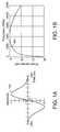
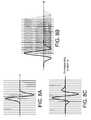
- FIG. 1Aillustrates a representative Gaussian Monocycle waveform in the time domain
- FIG. 1Billustrates the frequency domain amplitude of the Gaussian Monocycle of FIG. 1A
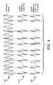
- FIG. 2Aillustrates a pulse train comprising pulses as in FIG. 1A;
- FIG. 2Billustrates the frequency domain amplitude of the waveform of FIG. 2A
- FIG. 3illustrates the frequency domain amplitude of a sequence of time coded pulses
- FIG. 4illustrates a typical received signal and interference signal
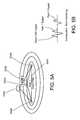
- FIG. 5Aillustrates a typical geometrical configuration giving rise to multipath received signals
- FIG. 5Billustrates exemplary multipath signals in the time domain
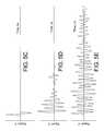
- FIGS. 5C-5Eillustrate a signal plot of various multipath environments.
- FIG. 5Fillustrates a plurality of multipaths with a plurality of reflectors from a transmitter to a receiver.
- FIG. 5Ggraphically represents signal strength as volts vs. time in a direct path and multipath environment.
- FIG. 6illustrates a representative impulse radio transmitter functional diagram
- FIG. 7illustrates a representative impulse radio receiver functional diagram
- FIG. 8Aillustrates a representative received pulse signal at the input to the correlator
- FIG. 8Billustrates a sequence of representative impulse signals in the correlation process
- FIG. 8Cillustrates the output of the correlator for each of the time offsets of FIG. 8 B.
- FIG. 9is a block diagram of an impulse radio interactive wireless gaming system in accordance with the present invention.
- FIG. 10is an electrical block diagram of a preferred embodiment of the impulse radio interactive wireless gaming unit in accordance with the present invention.
- FIG. 11is a timing diagram of the interactive impulse radio wireless gaming system showing typical system signaling strategies in the preferred embodiment according to the present invention.
- FIG. 12is a flowchart of the interactive impulse radio wireless gaming system showing the host operation in the preferred embodiment according to the present invention.
- FIG. 13is a flowchart of the interactive impulse wireless gaming system showing distributive interactive gaming in the preferred embodiment according to the present invention.
- FIG. 14is a graphic illustration showing a typical animation sequence in the preferred embodiment according to the present invention.
- impulse radioultra wideband technology
- UWBultra wideband technology
- impulse radioimpulse radio communications systems
- a second generation of impulse radio patentsincludes U.S. Pat. Nos. 5,677,927 (issued Oct. 14, 1997), 5,687,169 (issued Nov. 11, 1997) and 5,832,035 (issued Nov. 3, 1998) to Fullerton et al.
- Impulse radiorefers to a radio system based on short, low duty cycle pulses.
- An ideal impulse radio waveformis a short Gaussian monocycle. As the name suggests, this waveform attempts to approach one cycle of radio frequency (RF) energy at a desired center frequency. Due to implementation and other spectral limitations, this waveform may be altered significantly in practice for a given application. Most waveforms with enough bandwidth approximate a Gaussian shape to a useful degree.
- RFradio frequency
- Impulse radiocan use many types of modulation, including AM, time shift (also referred to as pulse position) and M-ary versions.
- the time shift methodhas simplicity and power output advantages that make it desirable.
- the time shift methodis used as an illustrative example.
- the pulse-to-pulse intervalcan be varied on a pulse-by-pulse basis by two components: an information component and a code component.
- conventional spread spectrum systemsemploy codes to spread the normally narrow band information signal over a relatively wide band of frequencies.
- a conventional spread spectrum receivercorrelates these signals to retrieve the original information signal.
- codesare not needed for energy spreading because the monocycle pulses themselves have an inherently wide bandwidth. Instead, codes are used for channelization, energy smoothing in the frequency domain, resistance to interference, and reducing the interference potential to nearby receivers.
- the impulse radio receiveris typically a direct conversion receiver with a cross correlator front end which coherently converts an electromagnetic pulse train of monocycle pulses to a baseband signal in a single stage.
- the baseband signalis the basic information signal for the impulse radio communications system. It is often found desirable to include a subcarrier with the baseband signal to help reduce the effects of amplifier drift and low frequency noise.
- the subcarrierthat is typically implemented alternately reverses modulation according to a known pattern at a rate faster than the data rate. This same pattern is used to reverse the process and restore the original data pattern just before detection.
- This methodpermits alternating current (AC) coupling of stages, or equivalent signal processing to eliminate direct current (DC) drift and errors from the detection process. This method is described in detail in U.S. Pat. No. 5,677,927 to Fullerton et al.
- each data bittypically time position modulates many pulses of the periodic timing signal. This yields a modulated, coded timing signal that comprises a train of pulses for each single data bit.
- the impulse radio receiverintegrates multiple pulses to recover the transmitted information.
- Impulse radiorefers to a radio system based on short, low duty cycle pulses.
- the resulting waveformapproaches one cycle per pulse at the center frequency.
- each pulseconsists of a burst of cycles usually with some spectral shaping to control the bandwidth to meet desired properties such as out of band emissions or in-band spectral flatness, or time domain peak power or burst off time attenuation.
- f mono ⁇ ( t )e ⁇ ( t ⁇ ) ⁇ e - t 2 2 ⁇ ⁇ ⁇ 2
- ⁇is a time scaling parameter
- f mono (t)is the waveform voltage
- eis the natural logarithm base.
- pulsesmay be produced by methods described in the patents referenced above or by other methods that are known to one of ordinary skill in the art. Any practical implementation will deviate from the ideal mathematical model by some amount. In fact, this deviation from ideal may be substantial and yet yield a system with acceptable performance. This is especially true for microwave implementations, where precise waveform shaping is difficult to achieve.
- These mathematical modelsare provided as an aid to describing ideal operation and are not intended to limit the invention. In fact, any burst of cycles that adequately fills a given bandwidth and has an adequate on-off attenuation ratio for a given application will serve the purpose of this invention.
- Impulse radio systemscan deliver one or more data bits per pulse; however, impulse radio systems more typically use pulse trains, not single pulses, for each data bit. As described in detail in the following example system, the impulse radio transmitter produces and outputs a train of pulses for each bit of information.
- FIGS. 2A and 2Bare illustrations of the output of a typical 10 Mpps system with uncoded, unmodulated, 0.5 nanosecond (ns) pulses 102 .
- FIG. 2Ashows a time domain representation of this sequence of pulses 102 .
- FIG. 2Bwhich shows 60 MHZ at the center of the spectrum for the waveform of FIG. 2A, illustrates that the result of the pulse train in the frequency domain is to produce a spectrum comprising a set of lines 204 spaced at the frequency of the 10 Mpps pulse repetition rate.
- the envelope of the line spectrumfollows the curve of the single pulse spectrum 104 of FIG. 1 B.
- the power of the pulse trainis spread among roughly two hundred comb lines. Each comb line thus has a small fraction of the total power and presents much less of an interference problem to a receiver sharing the band.
- impulse radio systemstypically have very low average duty cycles resulting in average power significantly lower than peak power.
- the duty cycle of the signal in the present exampleis 0.5%, based on a 0.5 ns pulse in a 100 ns interval.
- FIG. 3is a plot illustrating the impact of a pseudo-noise (PN) code dither on energy distribution in the frequency domain (A pseudo-noise, or PN code is a set of time positions defining pseudo-random positioning for each pulse in a sequence of pulses).
- PN codeis a set of time positions defining pseudo-random positioning for each pulse in a sequence of pulses.
- FIG. 3when compared to FIG. 2B, shows that the impact of using a PN code is to destroy the comb line structure and spread the energy more uniformly. This structure typically has slight variations that are characteristic of the specific code used.
- Codingalso provides a method of establishing independent communication channels using impulse radio. Codes can be designed to have low cross correlation such that a pulse train using one code will seldom collide on more than one or two pulse positions with a pulses train using another code during any one data bit time. Since a data bit may comprise hundreds of pulses, this represents a substantial attenuation of the unwanted channel.
- any aspect of the waveformcan be modulated to convey information.
- Amplitude modulation, phase modulation, frequency modulation, time shift modulation and M-ary versions of thesehave been proposed. Both analog and digital forms have been implemented. Of these, digital time shift modulation has been demonstrated to have various advantages and can be easily implemented using a correlation receiver architecture.
- Digital time shift modulationcan be implemented by shifting the coded time position by an additional amount (that is, in addition to code dither) in response to the information signal. This amount is typically very small relative to the code shift. In a 10 Mpps system with a center frequency of 2 GHz., for example, the code may command pulse position variations over a range of 100 ns; whereas, the information modulation may only deviate the pulse position by 150 ps.
- each pulseis delayed a different amount from its respective time base clock position by an individual code delay amount plus a modulation amount, where n is the number of pulses associated with a given data symbol digital bit.
- Modulationfurther smooths the spectrum, minimizing structure in the resulting spectrum.
- impulse radiosare able to perform in these environments, in part, because they do not depend on receiving every pulse.
- the impulse radio receiverperforms a correlating, synchronous receiving function (at the RF level) that uses a statistical sampling and combining of many pulses to recover the transmitted information.
- Impulse radio receiverstypically integrate from 1 to 1000 or more pulses to yield the demodulated output.
- the optimal number of pulses over which the receiver integratesis dependent on a number of variables, including pulse rate, bit rate, interference levels, and range.
- impulse radiosare highly resistant to interference from all radio communications systems, including other impulse radio transmitters. This is critical as any other signals within the band occupied by an impulse signal potentially interfere with the impulse radio. Since there are currently no unallocated bands available for impulse systems, they must share spectrum with other conventional radio systems without being adversely affected.
- the codehelps impulse systems discriminate between the intended impulse transmission and interfering transmissions from others.
- FIG. 4illustrates the result of a narrow band sinusoidal interference signal 402 overlaying an impulse radio signal 404 .
- the input to the cross correlationwould include the narrow band signal 402 , as well as the received ultrawide-band impulse radio signal 404 .
- the inputis sampled by the cross correlator with a code dithered template signal 406 .
- the cross correlationwould sample the interfering signal 402 with such regularity that the interfering signals could cause significant interference to the impulse radio receiver.
- the transmitted impulse signalis encoded with the code dither (and the impulse radio receiver template signal 406 is synchronized with that identical code dither)
- the correlationsamples the interfering signals non-uniformly.
- the samples from the interfering signaladd incoherently, increasing roughly according to square root of the number of samples integrated; whereas, the impulse radio samples add coherently, increasing directly according to the number of samples integrated.
- integrating over many pulsesovercomes the impact of interference.
- Impulse radiois resistant to interference because of its large processing gain.
- processing gainwhich quantifies the decrease in channel interference when wide-band communications are used, is the ratio of the bandwidth of the channel to the bit rate of the information signal.
- a direct sequence spread spectrum system with a 10 KHz information bandwidth and a 10 MHz channel bandwidthyields a processing gain of 1000 or 30 dB.
- far greater processing gainsare achieved by impulse radio systems, where the same 10 KHz information bandwidth is spread across a much greater 2 GHz channel bandwidth, resulting in a theoretical processing gain of 200,000 or 53 dB.
- V 2 totis the total interference signal to noise ratio variance, at the receiver
- Nis the number of interfering users
- ⁇ 2is the signal to noise ratio variance resulting from one of the interfering signals with a single pulse cross correlation
- Zis the number of pulses over which the receiver integrates to recover the modulation.
- impulse radiois its resistance to multipath fading effects.
- Conventional narrow band systemsare subject to multipath through the Rayleigh fading process, where the signals from many delayed reflections combine at the receiver antenna according to their seemingly random relative phases. This results in possible summation or possible cancellation, depending on the specific propagation to a given location.
- This situationoccurs where the direct path signal is weak relative to the multipath signals, which represents a major portion of the potential coverage of a radio system.
- thisresults in wild signal strength fluctuations as a function of distance traveled, where the changing mix of multipath signals results in signal strength fluctuations for every few feet of travel.
- Impulse radioscan be substantially resistant to these effects. Impulses arriving from delayed multipath reflections typically arrive outside of the correlation time and thus can be ignored. This process is described in detail with reference to FIGS. 5A and 5B.
- FIG. 5Athree propagation paths are shown.
- the direct path representing the straight-line distance between the transmitter and receiveris the shortest.
- Path 1represents a grazing multipath reflection, which is very close to the direct path.
- Path 2represents a distant multipath reflection.
- elliptical (or, in space, ellipsoidal) tracesthat represent other possible locations for reflections with the same time delay.
- FIG. 5Brepresents a time domain plot of the received waveform from this multipath propagation configuration.
- This figurecomprises three doublet pulses as shown in FIG. 1 A.
- the direct path signalis the reference signal and represents the shortest propagation time.
- the path 1 signalis delayed slightly and actually overlaps and enhances the signal strength at this delay value. Note that the reflected waves are reversed in polarity.
- the path 2 signalis delayed sufficiently that the waveform is completely separated from the direct path signal. If the correlator template signal is positioned at the direct path signal, the path 2 signal will produce no response. It can be seen that only the multipath signals resulting from very close reflectors have any effect on the reception of the direct path signal.
- the multipath signals delayed less than one quarter waveare the only multipath signals that can attenuate the direct path signal. This region is equivalent to the first Fresnel zone familiar to narrow band systems designers.
- Impulse radiohowever, has no further nulls in the higher Fresnel zones. The ability to avoid the highly variable attenuation from multipath gives impulse radio significant performance advantages.
- FIG. 5Aillustrates a typical multipath situation, such as in a building, where there are many reflectors 5 A 04 , 5 A 05 and multiple propagation paths 5 A 02 , 5 A 01 .
- a transmitter TX 5 A 06transmits a signal that propagates along the multiple propagation paths 5 A 02 , 5 A 04 to receiver RX 5 A 08 , where the multiple reflected signals are combined at the antenna.
- FIG. 5Billustrates a resulting typical received composite pulse waveform resulting from the multiple reflections and multiple propagation paths 5 A 01 , 5 A 02 .
- the direct path signal 5 A 01is shown as the first pulse signal received.
- the multiple reflected signals (“multipath signals”, or “multipath”)comprise the remaining response as illustrated.
- FIGS. 5C, 5 D, and 5 Erepresent the received signal from a TM-UWB transmitter in three different multipath environments. These figures are not actual signal plots, but are hand drawn plots approximating typical signal plots.
- FIG. 5Cillustrates the received signal in a very low multipath environment. This may occur in a building where the receiver antenna is in the middle of a room and is one meter from the transmitter. This may also represent signals received from some distance, such as 100 meters, in an open field where there are no objects to produce reflections. In this situation, the predominant pulse is the first received pulse and the multipath reflections are too weak to be significant.
- FIG. 5Dillustrates an intermediate multipath environment. This approximates the response from one room to the next in a building.
- FIG. 5Eapproximates the response in a severe multipath environment such as: propagation through many rooms; from corner to corner in a building; within a metal cargo hold of a ship; within a metal truck trailer; or within an intermodal shipping container.
- the main path signalis weaker than in FIG. 5 D.
- the direct path signal poweris small relative to the total signal power from the reflections.
- An impulse radio receivercan receive the signal and demodulate the information using either the direct path signal or any multipath signal peak having sufficient signal to noise ratio.
- the impulse radio receivercan select the strongest response from among the many arriving signals.
- dozens of reflectionswould have to be cancelled simultaneously and precisely while blocking the direct path—a highly unlikely scenario.
- This time separation of multipath signals together with time resolution and selection by the receiverpermit a type of time diversity that virtually eliminates cancellation of the signal.
- performanceis further improved by collecting the signal power from multiple signal peaks for additional signal to noise performance.
- the received signalis a sum of a large number of sine waves of random amplitude and phase.
- ris the envelope amplitude of the combined multipath signals
- 2 ⁇ 2is the RMS power of the combined multipath signals
- impulse radioIn a high multipath environment such as inside homes, offices, warehouses, automobiles, trailers, shipping containers, or outside in the urban canyon or other situations where the propagation is such that the received signal is primarily scattered energy, impulse radio, according to the present invention, can avoid the Rayleigh fading mechanism that limits performance of narrow band systems.
- FIG. 5F and 5Gin a transmit and receive system in a high multipath environment 5 F 00 , wherein the transmitter 5 F 06 transmits to receiver 5 F 08 with the signals reflecting off reflectors 5 F 03 which form multipaths 5 F 02 .
- the direct pathis illustrated as 5 F 01 with the signal graphically illustrated at 5 G 02 , with the vertical axis being the signal strength in volts and horizontal axis representing time in nanoseconds.
- Multipath signalsare graphically illustrated at 5 G 04 .
- impulse systemscan measure distances to extremely fine resolution because of the absence of ambiguous cycles in the waveform.
- Narrow band systemsare limited to the modulation envelope and cannot easily distinguish precisely which RF cycle is associated with each data bit because the cycle-to-cycle amplitude differences are so small they are masked by link or system noise. Since the impulse radio waveform has no multi-cycle ambiguity, this allows positive determination of the waveform position to less than a wavelength—potentially, down to the noise floor of the system.
- This time position measurementcan be used to measure propagation delay to determine link distance, and once link distance is known, to transfer a time reference to an equivalently high degree of precision.
- the inventors of the present inventionhave built systems that have shown the potential for centimeter distance resolution, which is equivalent to about 30 ps of time transfer resolution. See, for example, U.S. Pat. No. 6,133,876, issued Oct. 17, 2000, titled “System and Method for Position Determination by Impulse Radio,” and U.S. Pat. No. 6,111,536, issued Aug. 29, 2000, titled “System and Method for Distance Measurement by Inphase and Quadrature Signals in a Radio System,” both of which are incorporated herein by reference.
- impulse radio technologyalong with Time Division Multiple Access algorithms and Time Domain packet radios can achieve geo-positioning capabilities in a radio network.
- This geo-positioning methodallows ranging to occur within a network of radios without the necessity of a full duplex exchange among every pair of radios.
- An exemplary embodiment of an impulse radio transmitter 602 of an impulse radio communication system having one subcarrier channelwill now be described with reference to FIG. 6 .
- the transmitter 602comprises a time base 604 that generates a periodic timing signal 606 .
- the time base 604typically comprises a voltage controlled oscillator (VCO), or the like, having a high timing accuracy and low jitter, on the order of picoseconds (ps).
- VCOvoltage controlled oscillator
- the voltage control to adjust the VCO center frequencyis set at calibration to the desired center frequency used to define the transmitter's nominal pulse repetition rate.
- the periodic timing signal 606is supplied to a precision timing generator 608 .
- the precision timing generator 608supplies synchronizing signals 610 to the code source 612 and utilizes the code source output 614 together with an internally generated subcarrier signal (which is optional) and an information signal 616 to generate a modulated, coded timing signal 618 .
- the code source 612comprises a storage device such as a random access memory (RAM), read only memory (ROM), or the like, for storing suitable codes and for outputting the PN codes as a code signal 614 .
- RAMrandom access memory
- ROMread only memory
- maximum length shift registers or other computational meanscan be used to generate the codes.
- An information source 620supplies the information signal 616 to the precision timing generator 608 .
- the information signal 616can be any type of intelligence, including digital bits representing voice, data, imagery, or the like, analog signals, or complex signals.
- a pulse generator 622uses the modulated, coded timing signal 618 as a trigger to generate output pulses.
- the output pulsesare sent to a transmit antenna 624 via a transmission line 626 coupled thereto.
- the output pulsesare converted into propagating electromagnetic pulses by the transmit antenna 624 .
- the electromagnetic pulsesare called the emitted signal, and propagate to an impulse radio receiver 702 , such as shown in FIG. 7, through a propagation medium, such as air, in a radio frequency embodiment.
- the emitted signalis wide-band or ultrawide-band, approaching a monocycle pulse as in FIG. 1 A.
- the emitted signalcan be spectrally modified by filtering of the pulses. This bandpass filtering will cause each monocycle pulse to have more zero crossings (more cycles) in the time domain.
- the impulse radio receivercan use a similar waveform as the template signal in the cross correlator for efficient conversion.
- an exemplary embodiment of an impulse radio receiver (hereinafter called the receiver) for the impulse radio communication systemis now described with reference to FIG. 7 .
- the receiver 702comprises a receive antenna 704 for receiving a propagated impulse radio signal 706 .
- a received signal 708is input to a cross correlator or sampler 710 via a receiver transmission line, coupled to the receive antenna 704 , and producing a baseband output 712 .
- the receiver 702also includes a precision timing generator 714 , which receives a periodic timing signal 716 from a receiver time base 718 .
- This time base 718is adjustable and controllable in time, frequency, or phase, as required by the lock loop in order to lock on the received signal 708 .
- the precision timing generator 714provides synchronizing signals 720 to the code source 722 and receives a code control signal 724 from the code source 722 .
- the precision timing generator 714utilizes the periodic timing signal 716 and code control signal 724 to produce a coded timing signal 726 .
- the template generator 728is triggered by this coded timing signal 726 and produces a train of template signal pulses 730 ideally having waveforms substantially equivalent to each pulse of the received signal 708 .
- the code for receiving a given signalis the same code utilized by the originating transmitter to generate the propagated signal.
- the timing of the template pulse trainmatches the timing of the received signal pulse train, allowing the received signal 708 to be synchronously sampled in the correlator 710 .
- the correlator 710ideally comprises a multiplier followed by a short term integrator to sum the multiplier product over the pulse interval.
- the output of the correlator 710is coupled to a subcarrier demodulator 732 , which demodulates the subcarrier information signal from the subcarrier.
- the purpose of the optional subcarrier process, when used,is to move the information signal away from DC (zero frequency) to improve immunity to low frequency noise and offsets.
- the output of the subcarrier demodulatoris then filtered or integrated in the pulse summation stage 734 .
- a digital system embodimentis shown in FIG. 7 .
- a sample and hold 736samples the output 735 of the pulse summation stage 734 synchronously with the completion of the summation of a digital bit or symbol.
- the output of sample and hold 736is then compared with a nominal zero (or reference) signal output in a detector stage 738 to determine an output signal 739 representing the digital state of the output voltage of sample and hold 736 .
- the baseband signal 712is also input to a lowpass filter 742 (also referred to as lock loop filter 742 ).
- a control loopcomprising the lowpass filter 742 , time base 718 , precision timing generator 714 , template generator 728 , and correlator 710 is used to generate an error signal 744 .
- the error signal 744provides adjustments to the adjustable time base 718 to time position the periodic timing signal 726 in relation to the position of the received signal 708 .
- transceiver embodimentsubstantial economy can be achieved by sharing part or all of several of the functions of the transmitter 602 and receiver 702 . Some of these include the time base 718 , precision timing generator 714 , code source 722 , antenna 704 , and the like.
- FIGS. 8A-8Cillustrate the cross correlation process and the correlation function.
- FIG. 8Ashows the waveform of a template signal.
- FIG. 8Bshows the waveform of a received impulse radio signal at a set of several possible time offsets.
- FIG. 8Crepresents the output of the correlator (multiplier and short time integrator) for each of the time offsets of FIG. 8 B.
- this graphdoes not show a waveform that is a function of time, but rather a function of time-offset. For any given pulse received, there is only one corresponding point that is applicable on this graph. This is the point corresponding to the time offset of the template signal used to receive that pulse. Further examples and details of precision timing can be found described in U.S. Pat. Nos. 5,677,927 and 6,304,623 both of which are incorporated herein by reference.
- An impulse radio communications systemcan employ FLIP modulation techniques to transmit and receive flip modulated impulse radio signals. Further, it can transmit and receive flip with shift modulated (also referred to as quadrature flip time modulated (QFTM)) impulse radio signals.
- FLIP modulation techniquescan be used to create two, four, or more different data states.
- Flip modulatorsinclude an impulse radio receiver with a time base, a precision timing generator, a template generator, a delay, first and second correlators, a data detector and a time base adjustor.
- the time baseproduces a periodic timing signal that is used by the precision timing generator to produce a timing trigger signal.
- the template generatoruses the timing trigger signal to produce a template signal.
- a delayreceives the template signal and outputs a delayed template signal.
- the data detectorproduces a data signal based on at least the first correlator output signal.
- the time base adjustorproduces a time base adjustment signal based on at least the second correlator output signal.
- the time base adjustment signalis used to synchronize the time base with the received impulse radio signal.
- Vector Modulationis a modulation technique which includes the steps of generating and transmitting a series of time-modulated pulses, each pulse delayed by one of four pre-determined time delay periods and representative of at least two data bits of information, and receiving and demodulating the series of time-modulated pulses to estimate the data bits associated with each pulse.
- the apparatusincludes an impulse radio transmitter and an impulse radio receiver.
- the transmittertransmits the series of time-modulated pulses and includes a transmitter time base, a time delay modulator, a code time modulator, an output stage, and a transmitting antenna.
- the receiverreceives and demodulates the series of time-modulated pulses using a receiver time base and two correlators, one correlator designed to operate after a pre-determined delay with respect to the other correlator.
- Each correlatorincludes an integrator and a comparator, and may also include an averaging circuit that calculates an average output for each correlator, as well as a track and hold circuit for holding the output of the integrators.
- the receiverfurther includes an adjustable time delay circuit that may be used to adjust the pre-determined delay between the correlators in order to improve detection of the series of time-modulated pulses.
- Multiple correlator receiversutilize multiple correlators that precisely measure the impulse response of a channel and wherein measurements can extend to the maximum communications range of a system, thus, not only capturing ultra-wideband propagation waveforms, but also information on data symbol statistics. Further, multiple correlators enable rake acquisition of pulses and thus faster acquisition, tracking implementations to maintain lock and enable various modulation schemes. Once a tracking correlator is synchronized and locked to an incoming signal, the scanning correlator can sample the received waveform at precise time delays relative to the tracking point. By successively increasing the time delay while sampling the waveform, a complete, time-calibrated picture of the waveform can be collected.
- a receivercomprises an adjustable time base to output a sliding periodic timing signal having an adjustable repetition rate and a decode timing modulator to output a decode signal in response to the periodic timing signal.
- the impulse radio signalis cross-correlated with the decode signal to output a baseband signal.
- the receiverintegrates T samples of the baseband signal and a threshold detector uses the integration results to detect channel coincidence.
- a receiver controllerstops sliding the time base when channel coincidence is detected.
- a counter and extra count logiccoupled to the controller, are configured to increment or decrement the address counter by one or more extra counts after each T pulses is reached in order to shift the code modulo for proper phase alignment of the periodic timing signal and the received impulse radio signal. This method is described in detail in U.S. Pat. No. 5,832,035 to Fullerton, incorporated herein by reference.
- a receiverobtains a template pulse train and a received impulse radio signal.
- the receivercompares the template pulse train and the received impulse radio signal to obtain a comparison result.
- the systemperforms a threshold check on the comparison result. If the comparison result passes the threshold check, the system locks on the received impulse radio signal.
- the systemmay also perform a quick check, a synchronization check, and/or a command check of the impulse radio signal.
- a receiverhas been developed which includes a baseband signal converter device and combines multiple converter circuits and an RF amplifier in a single integrated circuit package.
- Each converter circuitincludes an integrator circuit that integrates a portion of each RF pulse during a sampling period triggered by a timing pulse generator.
- the integrator capacitoris isolated by a pair of Schottky diodes connected to a pair of load resistors.
- a current equalizer circuitequalizes the current flowing through the load resistors when the integrator is not sampling.
- Current steering logictransfers load current between the diodes and a constant bias circuit depending on whether a sampling pulse is present.
- the power control systemscomprise a first transceiver that transmits an impulse radio signal to a second transceiver.
- a power control updateis calculated according to a performance measurement of the signal received at the second transceiver.
- the transmitter power of either transceiveris adjusted according to the power control update.
- Various performance measurementsare employed according to the current invention to calculate a power control update, including bit error rate, signal-to-noise ratio, and received signal strength, used alone or in combination. Interference is thereby reduced, which is particularly important where multiple impulse radios are operating in close proximity and their transmissions interfere with one another. Reducing the transmitter power of each radio to a level that produces satisfactory reception increases the total number of radios that can operate in an area without saturation. Reducing transmitter power also increases transceiver efficiency.
- the methodcomprises the steps of: (a) conveying the message in packets; (b) repeating conveyance of selected packets to make up a repeat package; and (c) conveying the repeat package a plurality of times at a repeat period greater than twice the occurrence period of the interference.
- the communicationmay convey a message from a proximate transmitter to a distal receiver, and receive a message by a proximate receiver from a distal transmitter.
- the methodcomprises the steps of: (a) providing interference indications by the distal receiver to the proximate transmitter; (b) using the interference indications to determine predicted noise periods; and (c) operating the proximate transmitter to convey the message according to at least one of the following: (1) avoiding conveying the message during noise periods; (2) conveying the message at a higher power during noise periods; (3) increasing error detection coding in the message during noise periods; (4) re-transmitting the message following noise periods; (5) avoiding conveying the message when interference is greater than a first strength; (6) conveying the message at a higher power when the interference is greater than a second strength; (7) increasing error detection coding in the message when the interference is greater than a third strength; and (8) re-transmitting a portion of the message after interference has subsided to less than a predetermined strength.
- Yet another improvement to impulse radioincludes moderating interference with impulse radio wireless control of an appliance; the control is affected by a controller remote from the appliance transmitting impulse radio digital control signals to the appliance.
- the control signalshave a transmission power and a data rate.
- the methodcomprises the steps of: (a) in no particular order: (1) establishing a maximum acceptable noise value for a parameter relating to interfering signals; (2) establishing a frequency range for measuring the interfering signals; (b) measuring the parameter for the interference signals within the frequency range; and (c) when the parameter exceeds the maximum acceptable noise value, effecting an alteration of transmission of the control signals.
- the improvements made in codingcan directly improve the characteristics of impulse radio as used in the present invention.
- Specialized coding techniquesmay be employed to establish temporal and/or non-temporal pulse characteristics such that a pulse train will possess desirable properties. Coding methods for specifying temporal and non-temporal pulse characteristics are described in commonly owned, co-pending applications entitled “A Method and Apparatus for Positioning Pulses in Time”, Ser. No. 09/592,249, and “A Method for Specifying Non-Temporal Pulse Characteristics”, Ser. No. 09/592,250, both filed Jun. 12, 2000, and both of which are incorporated herein by reference. Essentially, a temporal or non-temporal pulse characteristic value layout is defined, an approach for mapping a code to the layout is specified, a code is generated using a numerical code generation technique, and the code is mapped to the defined layout per the specified mapping approach.
- a temporal or non-temporal pulse characteristic value layoutmay be fixed or non-fixed and may involve value ranges, discrete values, or a combination of value ranges and discrete values.
- a value range layoutspecifies a range of values for a pulse characteristic that is divided into components that are each subdivided into subcomponents, which can be further subdivided, ad infinitum.
- a discrete value layoutinvolves uniformly or non-uniformly distributed discrete pulse characteristic values.
- a non-fixed layout(also referred to as a delta layout) involves delta values relative to some reference value such as the characteristic value of the preceding pulse.
- a fixed or non-fixed characteristic value layoutmay include one or more non-allowable regions within which a characteristic value of a pulse is not allowed.
- a method for specifying non-allowable regions to prevent code elements from mapping to non-allowed characteristic valuesis described in co-owned, co-pending application entitled “A Method for Specifying Non-Allowable Pulse Characteristics”, Ser. No. 09/592,289, filed Jun. 12, 2000 and incorporated herein by reference.
- a related method that conditionally positions pulses depending on whether or not code elements map to non-allowable regionsis described in co-owned, co-pending application, entitled “A Method and Apparatus for Positioning Pulses Using a Layout having Non-Allowable Regions”, Ser. No. 09/592,248 and incorporated herein by reference.
- a codeconsists of a number of code elements having integer or floating-point values.
- a code element valuemay specify a single pulse characteristic (e.g., pulse position in time) or may be subdivided into multiple components, each specifying a different pulse characteristic. For example, a code having seven code elements each subdivided into five components (c 0 -c 4 ) could specify five different characteristics of seven pulses.
- a method for subdividing code elements into componentsis described in commonly owned, co-pending application entitled “Method for Specifying Pulse Characteristics using Codes”, Ser. No. 09/592,290, filed Jun. 12, 2000 previously referenced and again incorporated herein by reference.
- each code element or code element componentmaps to a value range or discrete value within the defined characteristic value layout. If a value range layout is used an offset value is typically employed to specify an exact value within the value range mapped to by the code element or code element component.
- kis the index of a transmitter
- jis the index of a pulse within its pulse train
- ( ⁇ 1)f j (k) ,a j (k) , c j (k) , and b j (k)are the coded polarity, amplitude, width, and waveform of the jth pulse of the kth transmitter
- T j (k)is the coded time shift of the jth pulse of the kth transmitter.
- a designed codemay be generated using a quadratic congruential, hyperbolic congruential, linear congruential, Costas array or other such numerical code generation technique designed to generate codes guaranteed to have certain correlation properties.
- Each of these alternative code generation techniqueshas certain characteristics to be considered in relation to the application of the pulse transmission system employing the code. For example, Costas codes have nearly ideal autocorrelation properties but somewhat less than ideal cross-correlation properties, while linear congruential codes have nearly ideal cross-correlation properties but less than ideal autocorrelation properties.
- design tradeoffsmay require that a compromise between two or more code generation techniques be made such that a code is generated using a combination of two or more techniques.
- a pseudorandom codemay be generated using a computer's random number generator, binary shift-register(s) mapped to binary words, a chaotic code generation scheme, or another well-known technique.
- Such ‘random-like’ codesare attractive for certain applications since they tend to spread spectral energy over multiple frequencies while having ‘good enough’ correlation properties, whereas designed codes may have superior correlation properties but have spectral properties that may not be as suitable for a given application.
- Computer random number generator functionscommonly employ the linear congruential generation (LCG) method or the Additive Lagged-Fibonacci Generator (ALFG) method.
- Alternative methodsinclude inversive congruential generators, explicit-inversive congruential generators, multiple recursive generators, combined LCGs, chaotic code generators, and Optimal Golomb Ruler (OGR) code generators. Any of these or other similar methods can be used to generate a pseudorandom code without departing from the scope of the invention, as will be apparent to those skilled in the relevant art.
- Criteria to considermay include correlation properties, spectral properties, code length, non-allowable regions, number of code family members, or other pulse characteristics.
- a method for applying predefined criteria to codesis described in co-owned, co-pending application, entitled “A Method and Apparatus for Specifying Pulse Characteristics using a Code that Satisfies Predefined Criteria”, Ser. No. 09/592,288, filed Jun. 12, 2000 and is incorporated herein by reference.
- Codesmay be combined sequentially, nested, or sequentially nested, and code combinations may be repeated. Sequential code combinations typically involve transitioning from one code to the next after the occurrence of some event. For example, a code with properties beneficial to signal acquisition might be employed until a signal is acquired, at which time a different code with more ideal channelization properties might be used. Sequential code combinations may also be used to support multicast communications. Nested code combinations may be employed to produce pulse trains having desirable correlation and spectral properties. For example, a designed code may be used to specify value range components within a layout and a nested pseudorandom code may be used to randomly position pulses within the value range components.
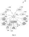
- FIG. 9shows a general block diagram of an interactive impulse radio wireless gaming system 900 of the present invention.
- a plurality of impulse radio wireless gaming unitsrepresented as four impulse radio wireless gaming units 910 A-D are shown which receive and transmit via impulse radio means periodically updated data signals from and to a game server 960 .
- the impulse radio interactive wireless gaming system 900provides full duplex operation between gaming units 910 A-D and the game server 960 using unique impulse radio channelization techniques described above and in the patents and patent applications incorporated herein by reference. Other methods of duplexing using impulse radios that have been described in the patents and patent applications herein incorporated by reference can also be used.
- the impulse radio duplex operationallows each gaming unit 910 A-D to operate alternately as a host device and as a guest device to transmit and receive data signals to and from the gaming unit 910 A-D and the game server 960 .
- games played using the wireless gaming units 910 A-D of the present inventioncan typically be played between two or more players, and can be relatively fast paced, such as action games engaging one player against another, as will be described in further detail below.
- a plurality of impulse radio wireless gaming unitsrepresented as four impulse radio wireless gaming units 910 A-D receive and transmit periodically updated data signals from and to a game server 960 over the impulse radio two-way paging system which also includes impulse radio pagers 920 A-D four of which are shown by way of example, and which can receive paging messages originated from a page origination device, such as a telephone 930 in communication with an impulse radio paging server 950 via an impulse radio interface 940 , in a manner well known to one of ordinary skill in the art of impulse radio technology. While impulse radio pagers are shown that can be two way pagers, conventional one way, or receive only pagers can be utilized albeit with less performance enhancements.
- paging transceivers using existing wireless techniqueswhich can receive messages and which can also provide an acknowledge back response can be utilized within the interactive impulse radio wireless gaming system as well. It will be appreciated that due to limitations in queuing of messages for transmission in such a conventional paging system, games played using the wireless gaming units 910 A-D of the present invention would typically be limited to relatively slow paced games played between two or more players, such a chess game or other game of strategy, so as to not conflict with the regular paging traffic.
- the game server 960through a local area network 970 , communicates with the impulse radio paging server 950 which controls the transmission and reception of periodically updated data signals to and from a impulse radio paging base station, depicted by ultra wide band antenna 980 .
- the periodically transmitted data signalscan include periodically updated relative position signals which are transmitted through the ultra wide band antenna 980 by the game server 960 via the impulse radio paging server 950 . It is appreciated that the position determination of each gaming unit 920 A-D can be determined using the novel position determination techniques enabled by impulse radio technology described in detail above and in the patents and patent applications herein incorporated by reference.
- the impulse radio paging transceiver 1010comprises an ultra wide band receiving antenna 1015 , an impulse radio transmitting ultra wide band antenna 1025 , an impulse radio receiver 1030 , an impulse radio interface 1035 output to decoder 1040 , an impulse radio transceiver controller 1045 , an encoder 1050 , and an impulse radio transmitter 1055 .
- the impulse radio wireless gaming unit processor 1020comprises a game random access memory (RAM) 1060 , a game read only memory (ROM) 1065 , an impulse radio wireless gaming unit controller 1070 , a graphics ROM 1075 , a clock 1080 , a user input device 1085 , a display 1090 , a sound transducer 1095 , and optionally a modem 1097 .
- the receiving ultra wide band antenna 1015is coupled to the impulse radio receiver 1030 for receiving and detecting transmitted selective call paging signals and periodically updated data signals.
- a serial stream of datais provided at the output of impulse radio receiver 1030 corresponding to the selective call paging signals and the periodically updated data signals received via impulse radio wireless means.
- the selective call paging signalsare coupled to a decoder 1040 , via an optional impulse radio interface 1035 to facilitate communication, which is implemented using a microprocessor in a manner well known to one of ordinary skill in the art.
- the decoder 1040communicates with a an impulse radio transceiver controller 1045 which is responsive to a plurality of control signals generated by the decoder 1040 .
- the paging impulse radio transceiver controller 1045communicates with an encoder 1050 and an impulse radio transmitter 1055 via an impulse radio interface 1052 along with the transmitting ultra wide band antenna 1025 to allow for the dissemination of a plurality of control signals and data signals. While a separate ultra wide band receiving antenna 1015 and transmitting antenna 1025 are shown in FIG. 10, it will be appreciated that a single receiving/transmitting antenna suitably coupled to the receiver 1030 and to the transmitter 1055 can be utilized to receive and transmit the periodically updated data signals as well.
- impulse radio wireless gaming unit processor 1020gaming information received is sequentially stored as periodically updated data signals in a memory 1060 represented by a game RAM under the control of an impulse radio wireless gaming unit controller 1070 which is responsive to the plurality of control signals output from controller 1045 .
- the impulse radio wireless gaming unit controller 1070can be a standard industry microprocessor.
- Information, including graphics characterizations, which has been selected for display from game RAM 1060is exhibited through a display 1090 , such as an LCD display, under the control of the impulse radio wireless gaming unit controller 1070 .
- the graphic characterizations which are displayedcan be individually animated during the time interval between the periodic updates of the data signals, adding further to the realism of the game as will be further described below.
- the data signalsinclude relative position signals which provide a relative position of the graphic characterizations which represent a plurality of moveable objects when displayed.
- the relative position signalsrepresent a plurality of incremental positions of the moveable objects on the display.
- Information stored in game RAM 1060may be accessed through a user input device 1085 .
- Game ROM 1065contains all the firmware routines and instructions required by the impulse radio wireless gaming unit controller 1070 which is necessary to store and to display the received information. Game ROM 1065 also contains all of the menus required to select the readout of stored information as well as graphic representations of the plurality of moveable objects which are provided in conjunction with a graphics ROM 1075 .
- the wireless gaming unit 910 of the present inventionin addition can have means for coupling to a telephone network for receiving and communicating additional information directly to a central location, such as a game server. This is accomplished through a modem 1097 and a network interface 1099 . Verbal communications are further possible through the use of a sound transducer 1095 .
- FIG. 11shows a timing diagram depicting typical system signaling strategies for transmitting and receiving wireless messages which include gaming information generated by the gaming units 910 A-D in accordance with the preferred embodiment of the present invention.
- a gaming sessionis initiated at time T 1 which begins with the game server 960 receiving a control signal transmitted by User A 910 A.
- User B 910 Bremains on a standby mode during this period.
- the game server 960transmits a game start signal which is received by User A and User B, 910 A and 910 B respectively, as a “Start Broadcast” signal.
- a paging signalmay be sent to User B 910 B to act to provide an alert signaling the initiation of a gaming session.
- the alertcan be audible, visual, or audible and visual.
- Users A and B, 910 A and 910 B respectivelytransmit a data signal signifying a movement in a graphic characterization or another action update while the game server 960 receives the data signals.
- the game server 960transmits updated data signals which are received by Users A and 13 , 910 A and 910 B respectively. This process continues throughout time T 5 and T 6 until time T 7 is reached at which the game server 960 receives a control signal signifying the end of the gaming session from User A 910 A.
- User B 910 Bcontinues to transmit either a movement in a graphic characterization or another action update at time T 7 .
- the game server 960transmits a final update received by User B 910 B while User A 910 A remains in a standby mode in preparation for another gaming session.
- FIG. 11is exemplary of a typical gaming session which may progress over a period of seconds to hours.
- FIG. 12a flowchart showing the operation of a host device in the preferred embodiment of the present invention is depicted.
- a new gaming sessionis initialized as shown in block 1200 .
- a number of gaming userscan be selected by the gaming user and a page is sent via the game server 960 to other gaming members to alert them as to the starting time as well as ending time of a particular gaming session as shown in block 1205 .
- a looping sequenceis next entered at block 1210 whereupon the gaming users provide updates to all information regarding the current game, such as graphic characterizations and other gaming information in block 1215 , after which at the appropriate time the information is broadcast.
- the looping sequence 1210begins anew.
- the information receivedis checked as to whether the gaming user responding is logging on, logging off, or updating information at block 1225 .
- a member participant listis updated at block 1230 from the information received in block 1225 , and then checked as to whether any gaming users remain at block 1245 , at which point, if no other gaming users remain, the gaming session is terminated as shown in block 1255 .
- the game grid including graphic characterizations as well as other information provided by the gaming usersis updated at block 1240 , and the updates are broadcast by the game server 960 at block 1250 , and the looping sequence of block 1210 begins again.
- FIG. 13a basic system flow diagram is shown for the preferred embodiment of the present invention.
- Softwareis first acquired from any number of sources which are apparent to those skilled in the art as shown in block 1300 .
- An active accountis next created with a game service provider such as America On-Line or Compuserve as shown in block 1305 .
- a local gamecan be established with the game server 960 included in a device such as the Sony Game Station trade named, “Sony Play Station.” It is also understood that any other gaming device with concomitant server can be utilized herein.
- the gaming userinitiates a standard logon procedure at block 1310 at which time the game server 960 responds with a current list of active gaming sessions ready to begin or already in progress as shown in block 1320 .
- the gaming useris then given a choice whether to enter an active gaming session at block 1325 or initiate a new gaming session at block 1330 .
- the gaming usermay initially play against a computer at step 1340 if no other gaming users are available.
- a decisionis made as to which gaming session to enter and the session is initiated at block 1335 .
- the usermay discontinue the gaming session at block 1345 and the session is ended as shown in block 1350 .
- FIG. 14shows a typical animation sequence within a wireless gaming session, and which by way of example shows a graphic characterization of a tank battle as provided by the preferred embodiment of the present invention.
- a gaming unit 910having a display 1090 and user input devices 1085 A through 1085 F is generally shown.
- Present positions of movable objects 1400 and 1402are depicted as graphic characterizations of battle-tanks displayed at a given instance of time on the display 1090 .
- the relative position signalsrepresent a plurality of incremental positions of the moveable objects 1400 and 1402 on the display 1020 .
- individually animated graphic characterizationscan be provided, such as graphic characterization 1404 and 1406 which depict, for example, growing from small to large and representing an actual event, an explosion of an artillery shell.
- an impulse radio interactive wireless gaming systemwhich includes a plurality of impulse radio wireless gaming units operating alternately as a host device and a guest device over a communication system such as provided by a dedicated impulse radio two-way paging system or a conventional two-way paging system or communicating directly with a local server with said local server possessing an impulse radio transceiver therein.
- the wireless gaming unitsinclude an impulse radio receiver for receiving wireless messages including gaming information generated by an impulse radio wireless gaming server or another impulse radio wireless gaming unit, the gaming information including data signals which are periodically updated and which indicate a present position of a plurality of moveable objects moving periodically as the data signals are updated.
- the wireless gaming unitshave a display for displaying the gaming information received in a form of graphic characterizations depicting moveable objects, a processor for providing updated gaming information at the gaming units, and a transmitter for transmitting wireless responses to the wireless gaming server or to another wireless gaming unit to provide the updated gaming information.
Landscapes
- Engineering & Computer Science (AREA)
- Multimedia (AREA)
- Computer Networks & Wireless Communication (AREA)
- Mobile Radio Communication Systems (AREA)
Abstract
Description


Claims (21)
Priority Applications (1)
| Application Number | Priority Date | Filing Date | Title |
|---|---|---|---|
| US09/873,747US6585597B2 (en) | 2000-09-20 | 2001-06-04 | Impulse radio interactive wireless gaming system, gaming unit, game server and method |
Applications Claiming Priority (2)
| Application Number | Priority Date | Filing Date | Title |
|---|---|---|---|
| US09/666,115US6354946B1 (en) | 2000-09-20 | 2000-09-20 | Impulse radio interactive wireless gaming system and method |
| US09/873,747US6585597B2 (en) | 2000-09-20 | 2001-06-04 | Impulse radio interactive wireless gaming system, gaming unit, game server and method |
Related Parent Applications (1)
| Application Number | Title | Priority Date | Filing Date |
|---|---|---|---|
| US09/666,115ContinuationUS6354946B1 (en) | 2000-09-20 | 2000-09-20 | Impulse radio interactive wireless gaming system and method |
Publications (2)
| Publication Number | Publication Date |
|---|---|
| US20020052239A1 US20020052239A1 (en) | 2002-05-02 |
| US6585597B2true US6585597B2 (en) | 2003-07-01 |
Family
ID=24672889
Family Applications (2)
| Application Number | Title | Priority Date | Filing Date |
|---|---|---|---|
| US09/666,115Expired - Fee RelatedUS6354946B1 (en) | 2000-09-20 | 2000-09-20 | Impulse radio interactive wireless gaming system and method |
| US09/873,747Expired - Fee RelatedUS6585597B2 (en) | 2000-09-20 | 2001-06-04 | Impulse radio interactive wireless gaming system, gaming unit, game server and method |
Family Applications Before (1)
| Application Number | Title | Priority Date | Filing Date |
|---|---|---|---|
| US09/666,115Expired - Fee RelatedUS6354946B1 (en) | 2000-09-20 | 2000-09-20 | Impulse radio interactive wireless gaming system and method |
Country Status (3)
| Country | Link |
|---|---|
| US (2) | US6354946B1 (en) |
| AU (1) | AU2001266841A1 (en) |
| WO (1) | WO2002024290A1 (en) |
Cited By (92)
| Publication number | Priority date | Publication date | Assignee | Title |
|---|---|---|---|---|
| US20030040354A1 (en)* | 2001-08-27 | 2003-02-27 | Yuri Itkis | Bingo paper |
| US20030199321A1 (en)* | 2002-04-22 | 2003-10-23 | Williams Richard C. | Gaming system allowing location determination of a gaming unit in a casino |
| US20040185881A1 (en)* | 2003-02-28 | 2004-09-23 | Lucent Technologies Inc. | Location-based ad-hoc game services |
| US20050288100A1 (en)* | 2002-07-24 | 2005-12-29 | Koninklijke Phlips Electronics N.V. | Performing a competition between teams by means of modular units |
| US20070060305A1 (en)* | 2005-07-08 | 2007-03-15 | Amaitis Lee M | System and method for wireless gaming system with user profiles |
| US20070162964A1 (en)* | 2006-01-12 | 2007-07-12 | Wang Liang-Yun | Embedded system insuring security and integrity, and method of increasing security thereof |
| US20070183535A1 (en)* | 2001-03-26 | 2007-08-09 | Irena Maravic | Sampling method for a spread spectrum communication system |
| US20070242026A1 (en)* | 2006-04-14 | 2007-10-18 | Qualcomm Incorporated | Apparatus and method of pulse generation for ultra-wideband transmission |
| US20070248114A1 (en)* | 2006-04-20 | 2007-10-25 | Qualcomm Incorporated | Media access control for ultra-wide band communication |
| US20070258507A1 (en)* | 2006-04-26 | 2007-11-08 | Qualcomm Incorporated | Inter-pulse duty cycling |
| US20070257827A1 (en)* | 2006-04-20 | 2007-11-08 | Qualcomm Incorporated | Low power output stage |
| US20070281782A1 (en)* | 2004-02-25 | 2007-12-06 | Amaitis Lee M | System and method for convenience gaming |
| US20070279237A1 (en)* | 2006-04-26 | 2007-12-06 | Qualcomm Incorporated | Wireless localization apparatus and method |
| US20070286274A1 (en)* | 2006-04-19 | 2007-12-13 | Qualcomm Incorporated | Apparatus and method of low latency multi-hop communication |
| US20080043824A1 (en)* | 2006-04-18 | 2008-02-21 | Qualcomm Incorporated | Offloaded processing for wireless applications |
| US20080112512A1 (en)* | 2006-11-15 | 2008-05-15 | Qualcomm Incorporated | Transmitted reference signaling scheme |
| US20080117804A1 (en)* | 2006-11-16 | 2008-05-22 | Qualcomm Incorporated | Multiple access techniques for a wireless communication medium |
| US20080117939A1 (en)* | 2006-11-16 | 2008-05-22 | Qualcomm Incorporated | Multiple access techniques for a wireless communiation medium |
| US20080116941A1 (en)* | 2006-11-16 | 2008-05-22 | Qualcomm Incorporated | Peak signal detector |
| US20080130685A1 (en)* | 2001-09-26 | 2008-06-05 | General Atomics | Method and Apparatus for Data Transfer Using a Time Division Multiple Frequency Scheme Supplemented with Polarity Modulation |
| US20080139310A1 (en)* | 2006-12-07 | 2008-06-12 | Kabushiki Kaisha Square Enix (Also Trading As Squa Re Enix Co., Ltd.) | Video game processing apparatus, a method and a computer program product for processing a video game |
| US20080144560A1 (en)* | 2006-12-15 | 2008-06-19 | Qualcomm Incorporated | Channel access scheme for ultra-wide band communication |
| US20080183289A1 (en)* | 2007-01-29 | 2008-07-31 | Werblin Research & Development Corp. | Intraocular lens system |
| US20080246548A1 (en)* | 2007-04-05 | 2008-10-09 | Qualcomm Incorporated | Method and apparatus for generating oscillating signals |
| US20080258562A1 (en)* | 2007-04-23 | 2008-10-23 | Qualcomm Incorporated | Apparatus and method for generating fine timing from coarse timing source |
| US20090016548A1 (en)* | 2007-07-10 | 2009-01-15 | Pavel Monat | Super regenerative (sr) apparatus having plurality of parallel sr amplifiers tuned to distinct frequencies |
| US20090017782A1 (en)* | 2007-07-12 | 2009-01-15 | Pavel Monat | Method for determining line-of-sight (los) distance between remote communications devices |
| US20090021408A1 (en)* | 2007-07-18 | 2009-01-22 | Lee Chong U | Adaptive dynamic range control |
| US20090034591A1 (en)* | 2007-07-30 | 2009-02-05 | David Jonathan Julian | Method of pairing devices |
| US20090061777A1 (en)* | 2007-08-28 | 2009-03-05 | Qualcomm Incorporated | Apparatus and method for modulating an amplitude, phase or both of a periodic signal on a per cycle basis |
| US20090067407A1 (en)* | 2007-09-11 | 2009-03-12 | Qualcomm Incorporated | Keep-alive for wireless networks |
| US20090080101A1 (en)* | 2007-09-21 | 2009-03-26 | Qualcomm Incorporated | Signal generator with adjustable frequency |
| US20090080568A1 (en)* | 2007-09-21 | 2009-03-26 | Qualcomm Incorporated | Signal generator with adjustable phase |
| US20090080542A1 (en)* | 2007-09-25 | 2009-03-26 | Qualcomm Incorporated | Interference Mitigation For Impulse-Based Communication |
| US20090086702A1 (en)* | 2007-09-28 | 2009-04-02 | Qualcomm Incorporated | Randomization of periodic channel scans |
| US7549576B2 (en) | 2006-05-05 | 2009-06-23 | Cfph, L.L.C. | Systems and methods for providing access to wireless gaming devices |
| US20090224832A1 (en)* | 2008-03-10 | 2009-09-10 | Qualcomm Incorporated | System and method of enabling a signal processing device in a relatively fast manner to process a low duty cycle signal |
| US20090224860A1 (en)* | 2008-03-10 | 2009-09-10 | Qualcomm Incorporated | System and method of using residual voltage from a prior operation to establish a bias voltage for a subsequent operation |
| US20090243699A1 (en)* | 2008-03-25 | 2009-10-01 | Qualcomm Incorporated | System and method of companding an input signal of an energy detecting receiver |
| US20090251208A1 (en)* | 2008-04-08 | 2009-10-08 | Qualcomm Incorporated | Low power slicer-based demodulator for ppm |
| US20090259671A1 (en)* | 2008-04-15 | 2009-10-15 | Qualcomm Incorporated | Synchronizing timing mismatch by data insertion |
| US20090270030A1 (en)* | 2008-04-23 | 2009-10-29 | Qualcomm Incorporated | Multi-level duty cycling |
| US20090279851A1 (en)* | 2008-04-09 | 2009-11-12 | Sony Corporation | Captured image data management method and image capturing apparatus |
| US7637810B2 (en) | 2005-08-09 | 2009-12-29 | Cfph, Llc | System and method for wireless gaming system with alerts |
| US20090323985A1 (en)* | 2008-06-30 | 2009-12-31 | Qualcomm Incorporated | System and method of controlling power consumption in response to volume control |
| US7644861B2 (en) | 2006-04-18 | 2010-01-12 | Bgc Partners, Inc. | Systems and methods for providing access to wireless gaming devices |
| US20100020863A1 (en)* | 2008-07-25 | 2010-01-28 | Qualcomm Incorporated | Determination of receive data values |
| US20100046443A1 (en)* | 2008-08-22 | 2010-02-25 | Qualcomm Incorporated | Addressing schemes for wireless communication |
| US7716001B2 (en) | 2006-11-15 | 2010-05-11 | Qualcomm Incorporated | Delay line calibration |
| US20100157886A1 (en)* | 2007-10-26 | 2010-06-24 | Qualcomm Incorporated | Preamble capture and medium access control |
| US20100172393A1 (en)* | 2009-01-06 | 2010-07-08 | Qualcomm Incorporated | Pulse arbitration for network communications |
| US20100241816A1 (en)* | 2009-03-19 | 2010-09-23 | Qualcolmm Incorporated | Optimized transfer of packets in a resource constrained operating environment |
| US7811172B2 (en) | 2005-10-21 | 2010-10-12 | Cfph, Llc | System and method for wireless lottery |
| US7855611B2 (en) | 2006-11-15 | 2010-12-21 | Qualcomm Incorporated | Delay line calibration |
| US7965805B2 (en) | 2007-09-21 | 2011-06-21 | Qualcomm Incorporated | Signal generator with signal tracking |
| US20110231657A1 (en)* | 2009-03-16 | 2011-09-22 | Qualcomm Incorporated | Apparatus and method for employing codes for telecommunications |
| US8070604B2 (en) | 2005-08-09 | 2011-12-06 | Cfph, Llc | System and method for providing wireless gaming as a service application |
| US8092303B2 (en) | 2004-02-25 | 2012-01-10 | Cfph, Llc | System and method for convenience gaming |
| US20120129607A1 (en)* | 2009-03-03 | 2012-05-24 | E3 Llc | System and method for game play in a dynamic communication network |
| US8292741B2 (en) | 2006-10-26 | 2012-10-23 | Cfph, Llc | Apparatus, processes and articles for facilitating mobile gaming |
| US8319601B2 (en) | 2007-03-14 | 2012-11-27 | Cfph, Llc | Game account access device |
| US8375261B2 (en) | 2008-07-07 | 2013-02-12 | Qualcomm Incorporated | System and method of puncturing pulses in a receiver or transmitter |
| US8406794B2 (en) | 2006-04-26 | 2013-03-26 | Qualcomm Incorporated | Methods and apparatuses of initiating communication in wireless networks |
| US8483639B2 (en) | 2008-05-06 | 2013-07-09 | Qualcomm Incorporated | AGC for slicer-based low power demodulator |
| US8504617B2 (en) | 2004-02-25 | 2013-08-06 | Cfph, Llc | System and method for wireless gaming with location determination |
| US8510567B2 (en) | 2006-11-14 | 2013-08-13 | Cfph, Llc | Conditional biometric access in a gaming environment |
| US8514911B2 (en) | 2009-05-13 | 2013-08-20 | Qualcomm Incorporated | Method and apparatus for clock drift compensation during acquisition in a wireless communication system |
| US8538345B2 (en) | 2007-10-09 | 2013-09-17 | Qualcomm Incorporated | Apparatus including housing incorporating a radiating element of an antenna |
| US8552903B2 (en) | 2006-04-18 | 2013-10-08 | Qualcomm Incorporated | Verified distance ranging |
| US8581721B2 (en) | 2007-03-08 | 2013-11-12 | Cfph, Llc | Game access device with privileges |
| US8600373B2 (en) | 2006-04-26 | 2013-12-03 | Qualcomm Incorporated | Dynamic distribution of device functionality and resource management |
| US8645709B2 (en) | 2006-11-14 | 2014-02-04 | Cfph, Llc | Biometric access data encryption |
| US8784197B2 (en) | 2006-11-15 | 2014-07-22 | Cfph, Llc | Biometric access sensitivity |
| US8837724B2 (en) | 2007-03-27 | 2014-09-16 | Qualcomm Incorporated | Synchronization test for device authentication |
| US8840018B2 (en) | 2006-05-05 | 2014-09-23 | Cfph, Llc | Device with time varying signal |
| US8886125B2 (en) | 2006-04-14 | 2014-11-11 | Qualcomm Incorporated | Distance-based association |
| US8956231B2 (en) | 2010-08-13 | 2015-02-17 | Cfph, Llc | Multi-process communication regarding gaming information |
| US8974302B2 (en) | 2010-08-13 | 2015-03-10 | Cfph, Llc | Multi-process communication regarding gaming information |
| US9141961B2 (en) | 2007-06-20 | 2015-09-22 | Qualcomm Incorporated | Management of dynamic mobile coupons |
| US9183693B2 (en) | 2007-03-08 | 2015-11-10 | Cfph, Llc | Game access device |
| US9215581B2 (en) | 2006-04-14 | 2015-12-15 | Qualcomm Incorported | Distance-based presence management |
| US9306952B2 (en) | 2006-10-26 | 2016-04-05 | Cfph, Llc | System and method for wireless gaming with location determination |
| US9483769B2 (en) | 2007-06-20 | 2016-11-01 | Qualcomm Incorporated | Dynamic electronic coupon for a mobile environment |
| US9524502B2 (en) | 2007-06-20 | 2016-12-20 | Qualcomm Incorporated | Management of dynamic electronic coupons |
| US9661472B2 (en) | 2015-05-29 | 2017-05-23 | Verity Studios Ag | Methods and systems for scheduling the transmission of localization signals and operating self-localizing apparatus |
| US9885773B2 (en) | 2015-03-07 | 2018-02-06 | Verity Studios Ag | Distributed localization systems and methods and self-localizing apparatus |
| US10143930B2 (en) | 2014-12-24 | 2018-12-04 | Verity Studios Ag | Flexibly supported movable platform having an actuator to move a display |
| US10460566B2 (en) | 2005-07-08 | 2019-10-29 | Cfph, Llc | System and method for peer-to-peer wireless gaming |
| US10542372B2 (en) | 2011-03-15 | 2020-01-21 | Qualcomm Incorporated | User identification within a physical merchant location through the use of a wireless network |
| US10613527B2 (en) | 2014-08-18 | 2020-04-07 | Verity Studios Ag | Invisible track for an interactive mobile robot system |
| US12400518B2 (en) | 2006-05-05 | 2025-08-26 | Interactive Games Llc | System for facilitating online wagering with nearby mobile phones |
| US12409382B2 (en) | 2010-08-13 | 2025-09-09 | Interactive Games Llc | Smart phone with wrapper application that checks whether the smart phone may use a gambling application |
Families Citing this family (74)
| Publication number | Priority date | Publication date | Assignee | Title |
|---|---|---|---|---|
| US8085813B2 (en)* | 1999-10-28 | 2011-12-27 | Lightwaves Systems, Inc. | Method for routing data packets using an IP address based on geo position |
| US6868419B1 (en)* | 1999-10-28 | 2005-03-15 | Lightwaves Systems Inc. | Method of transmitting data including a structured linear database |
| US6976034B1 (en) | 1999-10-28 | 2005-12-13 | Lightwaves Systems, Inc. | Method of transmitting data including a structured linear database |
| US9900734B2 (en) | 1999-10-28 | 2018-02-20 | Lightwaves Systems, Inc. | Method for routing data packets using an IP address based on geo position |
| US7147558B2 (en)* | 2000-03-22 | 2006-12-12 | Wms Gaming Inc. | System and method for dispensing gaming machine credits in multiple different media of monetary exchange |
| US6731313B1 (en)* | 2000-06-23 | 2004-05-04 | Igt | Gaming device having touch activated alternating or changing symbol |
| US7695363B2 (en) | 2000-06-23 | 2010-04-13 | Igt | Gaming device having multiple display interfaces |
| US7699699B2 (en) | 2000-06-23 | 2010-04-20 | Igt | Gaming device having multiple selectable display interfaces based on player's wagers |
| US6914949B2 (en)* | 2000-10-13 | 2005-07-05 | Time Domain Corporation | Method and system for reducing potential interference in an impulse radio |
| US6638170B1 (en)* | 2000-10-16 | 2003-10-28 | Igt | Gaming device network |
| US7470196B1 (en) | 2000-10-16 | 2008-12-30 | Wms Gaming, Inc. | Method of transferring gaming data on a global computer network |
| AU2002226956A1 (en) | 2000-11-22 | 2002-06-03 | Leap Wireless International, Inc. | Method and system for providing interactive services over a wireless communications network |
| US7574493B2 (en) | 2000-11-22 | 2009-08-11 | Cricket Communications, Inc. | Method and system for improving the efficiency of state information transfer over a wireless communications network |
| US6874029B2 (en) | 2000-11-22 | 2005-03-29 | Leap Wireless International, Inc. | Method and system for mediating interactive services over a wireless communications network |
| WO2002049732A1 (en)* | 2000-12-21 | 2002-06-27 | Telisar Corporation | System and method for portable interactive multi-player games and entertainment |
| US6437756B1 (en)* | 2001-01-02 | 2002-08-20 | Time Domain Corporation | Single element antenna apparatus |
| US6749510B2 (en)* | 2001-02-07 | 2004-06-15 | Wms Gaming Inc. | Centralized gaming system with modifiable remote display terminals |
| US6908389B1 (en)* | 2001-03-07 | 2005-06-21 | Nokia Corporation | Predefined messages for wireless multiplayer gaming |
| US20020176511A1 (en)* | 2001-03-16 | 2002-11-28 | Fullerton Larry W. | High pulse-rate radio-frequency apparatus and associated methods |
| US8766773B2 (en) | 2001-03-20 | 2014-07-01 | Lightwaves Systems, Inc. | Ultra wideband radio frequency identification system, method, and apparatus |
| US7545868B2 (en) | 2001-03-20 | 2009-06-09 | Lightwaves Systems, Inc. | High bandwidth data transport system |
| US7983349B2 (en)* | 2001-03-20 | 2011-07-19 | Lightwaves Systems, Inc. | High bandwidth data transport system |
| US20020174248A1 (en)* | 2001-05-16 | 2002-11-21 | Motorola, Inc. | Method and system for communicating chat and game messages in a wireless network |
| US8157645B1 (en)* | 2001-07-13 | 2012-04-17 | Bally Gaming, Inc. | System and method for providing a bonus with multiple remote inputs |
| JP4644988B2 (en)* | 2001-07-23 | 2011-03-09 | ソニー株式会社 | Wireless impulse transmitter, receiver and method |
| US7112138B2 (en)* | 2001-08-03 | 2006-09-26 | Igt | Player tracking communication mechanisms in a gaming machine |
| US8210927B2 (en) | 2001-08-03 | 2012-07-03 | Igt | Player tracking communication mechanisms in a gaming machine |
| US7927212B2 (en)* | 2001-08-03 | 2011-04-19 | Igt | Player tracking communication mechanisms in a gaming machine |
| US8784211B2 (en)* | 2001-08-03 | 2014-07-22 | Igt | Wireless input/output and peripheral devices on a gaming machine |
| US6760387B2 (en)* | 2001-09-21 | 2004-07-06 | Time Domain Corp. | Impulse radio receiver and method for finding angular offset of an impulse radio transmitter |
| EP1298811A1 (en)* | 2001-09-27 | 2003-04-02 | STMicroelectronics S.A. | Method and apparatus for detecting impulses from a received ultra wideband signal |
| US7722466B2 (en)* | 2002-03-06 | 2010-05-25 | Wms Gaming Inc. | Integration of casino gaming and non-casino interactive gaming |
| US7025678B2 (en)* | 2002-03-21 | 2006-04-11 | Sony Corporation | System and method for effectively implementing remote display devices in a gaming network |
| US7009348B2 (en)* | 2002-06-03 | 2006-03-07 | Systel Development & Industries Ltd. | Multiple channel ballast and networkable topology and system including power line carrier applications |
| US7221911B2 (en)* | 2002-08-16 | 2007-05-22 | Wisair Ltd. | Multi-band ultra-wide band communication method and system |
| US20040063498A1 (en)* | 2002-09-30 | 2004-04-01 | Sony Corporation | System and method for flexibly implementing a wireless gaming network |
| US7428258B2 (en)* | 2002-10-17 | 2008-09-23 | Time Domain Corporation | Method and apparatus for generating RF waveforms having aggregate energy with desired spectral characteristics |
| JP2004136009A (en) | 2002-10-21 | 2004-05-13 | Nintendo Co Ltd | Radio communication game system |
| JP3830442B2 (en)* | 2002-10-22 | 2006-10-04 | 任天堂株式会社 | Wireless communication game system, game device, information storage medium, and program |
| US7961705B2 (en)* | 2003-04-30 | 2011-06-14 | Lightwaves Systems, Inc. | High bandwidth data transport system |
| US8447900B1 (en)* | 2003-06-12 | 2013-05-21 | Marvell International Ltd. | Adaptive multiple FIFO scheme |
| JP4073885B2 (en) | 2003-06-17 | 2008-04-09 | 任天堂株式会社 | GAME SYSTEM, GAME DEVICE, AND GAME PROGRAM |
| AU2003903139A0 (en) | 2003-06-20 | 2003-07-03 | Resmed Limited | Breathable gas apparatus with humidifier |
| US20070093294A1 (en)* | 2003-09-19 | 2007-04-26 | Reza Serafat | Method and device for supporting wireless multi-player gaming with a multi-player game hub |
| US7347781B2 (en)* | 2004-03-03 | 2008-03-25 | Motorola, Inc. | Method and system for reality gaming on wireless devices |
| US8251791B2 (en) | 2004-08-19 | 2012-08-28 | Igt | Gaming system having multiple gaming machines which provide bonus awards |
| US7963847B2 (en) | 2004-08-19 | 2011-06-21 | Igt | Gaming system having multiple gaming machines which provide bonus awards |
| US8021230B2 (en) | 2004-08-19 | 2011-09-20 | Igt | Gaming system having multiple gaming machines which provide bonus awards |
| US7753773B2 (en)* | 2005-08-26 | 2010-07-13 | Igt | Gaming device having physical concentric symbol generators which are operable to provide a plurality of different games to a player |
| US8128491B2 (en) | 2005-09-09 | 2012-03-06 | Igt | Server based gaming system having multiple progressive awards |
| US7568973B2 (en) | 2005-09-09 | 2009-08-04 | Igt | Server based gaming system having multiple progressive awards |
| US7841939B2 (en) | 2005-09-09 | 2010-11-30 | Igt | Server based gaming system having multiple progressive awards |
| US8137188B2 (en) | 2005-09-09 | 2012-03-20 | Igt | Server based gaming system having multiple progressive awards |
| US20070066395A1 (en)* | 2005-09-20 | 2007-03-22 | Harris John M | System and method for improving player experience in wireless gaming |
| US20070249288A1 (en)* | 2006-04-14 | 2007-10-25 | Kamran Moallemi | Distance-based security |
| KR100730086B1 (en)* | 2006-07-10 | 2007-06-19 | 삼성전기주식회사 | Dual system transceiver |
| US8512130B2 (en) | 2006-07-27 | 2013-08-20 | Igt | Gaming system with linked gaming machines that are configurable to have a same probability of winning a designated award |
| US7674180B2 (en)* | 2006-09-27 | 2010-03-09 | Igt | Server based gaming system having system triggered loyalty award sequences |
| US8616959B2 (en) | 2006-09-27 | 2013-12-31 | Igt | Server based gaming system having system triggered loyalty award sequences |
| US7862430B2 (en)* | 2006-09-27 | 2011-01-04 | Igt | Server based gaming system having system triggered loyalty award sequences |
| US8162757B2 (en)* | 2007-03-07 | 2012-04-24 | Electronic Arts Inc. | Multiplayer platform for mobile applications |
| US20080262928A1 (en)* | 2007-04-18 | 2008-10-23 | Oliver Michaelis | Method and apparatus for distribution and personalization of e-coupons |
| US20090076911A1 (en)* | 2007-06-20 | 2009-03-19 | Dang Minh Vo | Mobile coupons utilizing peer to peer ranging |
| US7985133B2 (en) | 2007-07-30 | 2011-07-26 | Igt | Gaming system and method for providing an additional gaming currency |
| US8900053B2 (en) | 2007-08-10 | 2014-12-02 | Igt | Gaming system and method for providing different bonus awards based on different types of triggered events |
| US9142097B2 (en) | 2007-10-26 | 2015-09-22 | Igt | Gaming system and method for providing play of local first game and remote second game |
| US7944978B2 (en)* | 2007-10-29 | 2011-05-17 | Lightwaves Systems, Inc. | High bandwidth data transport system |
| US8608573B2 (en) | 2008-03-29 | 2013-12-17 | Hemanth Gundurao Kanekal | Electronic trading card and game system |
| US9039516B2 (en) | 2009-07-30 | 2015-05-26 | Igt | Concurrent play on multiple gaming machines |
| US9311777B2 (en) | 2012-08-17 | 2016-04-12 | Bally Gaming, Inc. | Systems, methods and devices for configuring wagering game systems and devices |
| US9875618B2 (en) | 2014-07-24 | 2018-01-23 | Igt | Gaming system and method employing multi-directional interaction between multiple concurrently played games |
| US9972171B2 (en) | 2015-09-24 | 2018-05-15 | Igt | Gaming system and method for providing a triggering event based on a collection of units from different games |
| US10924586B2 (en)* | 2018-05-30 | 2021-02-16 | International Business Machines Corporation | Aggregating virtual reality (VR) sessions |
| CA3211558A1 (en)* | 2021-03-10 | 2022-09-15 | Marco LURATI | Modular gaming system |
Citations (15)
| Publication number | Priority date | Publication date | Assignee | Title |
|---|---|---|---|---|
| US4572509A (en) | 1982-09-30 | 1986-02-25 | Sitrick David H | Video game network |
| US4641317A (en) | 1984-12-03 | 1987-02-03 | Charles A. Phillips | Spread spectrum radio transmission system |
| US4743906A (en) | 1984-12-03 | 1988-05-10 | Charles A. Phillips | Time domain radio transmission system |
| US4813057A (en) | 1984-12-03 | 1989-03-14 | Charles A. Phillips | Time domain radio transmission system |
| US4951039A (en) | 1988-04-18 | 1990-08-21 | Motorola, Inc. | Animated data display interleaving |
| US5048831A (en) | 1990-08-31 | 1991-09-17 | Sides Jim T | Electronic game apparatus and method of use |
| US5363108A (en) | 1984-12-03 | 1994-11-08 | Charles A. Phillips | Time domain radio transmission system |
| US5618045A (en) | 1995-02-08 | 1997-04-08 | Kagan; Michael | Interactive multiple player game system and method of playing a game between at least two players |
| US5677927A (en) | 1994-09-20 | 1997-10-14 | Pulson Communications Corporation | Ultrawide-band communication system and method |
| US5687169A (en) | 1995-04-27 | 1997-11-11 | Time Domain Systems, Inc. | Full duplex ultrawide-band communication system and method |
| US5738583A (en) | 1996-02-02 | 1998-04-14 | Motorola, Inc. | Interactive wireless gaming system |
| US5832035A (en) | 1994-09-20 | 1998-11-03 | Time Domain Corporation | Fast locking mechanism for channelized ultrawide-band communications |
| US5942969A (en) | 1997-01-23 | 1999-08-24 | Sony Corporation | Treasure hunt game using pager and paging system |
| GB2344539A (en) | 1998-12-08 | 2000-06-14 | Multitone Electronics Plc | Electronic game with receiver for paging signals |
| US6133876A (en) | 1998-03-23 | 2000-10-17 | Time Domain Corporation | System and method for position determination by impulse radio |
- 2000
- 2000-09-20USUS09/666,115patent/US6354946B1/ennot_activeExpired - Fee Related
- 2001
- 2001-06-04USUS09/873,747patent/US6585597B2/ennot_activeExpired - Fee Related
- 2001-06-11WOPCT/US2001/018790patent/WO2002024290A1/enactiveApplication Filing
- 2001-06-11AUAU2001266841Apatent/AU2001266841A1/ennot_activeAbandoned
Patent Citations (17)
| Publication number | Priority date | Publication date | Assignee | Title |
|---|---|---|---|---|
| US4572509A (en) | 1982-09-30 | 1986-02-25 | Sitrick David H | Video game network |
| US4641317A (en) | 1984-12-03 | 1987-02-03 | Charles A. Phillips | Spread spectrum radio transmission system |
| US4743906A (en) | 1984-12-03 | 1988-05-10 | Charles A. Phillips | Time domain radio transmission system |
| US4813057A (en) | 1984-12-03 | 1989-03-14 | Charles A. Phillips | Time domain radio transmission system |
| US4979186A (en) | 1984-12-03 | 1990-12-18 | Charles A. Phillips | Time domain radio transmission system |
| US5363108A (en) | 1984-12-03 | 1994-11-08 | Charles A. Phillips | Time domain radio transmission system |
| US4951039A (en) | 1988-04-18 | 1990-08-21 | Motorola, Inc. | Animated data display interleaving |
| US5048831A (en) | 1990-08-31 | 1991-09-17 | Sides Jim T | Electronic game apparatus and method of use |
| US5832035A (en) | 1994-09-20 | 1998-11-03 | Time Domain Corporation | Fast locking mechanism for channelized ultrawide-band communications |
| US5677927A (en) | 1994-09-20 | 1997-10-14 | Pulson Communications Corporation | Ultrawide-band communication system and method |
| US6031862A (en) | 1994-09-20 | 2000-02-29 | Time Domain Corporation | Ultrawide-band communication system and method |
| US5618045A (en) | 1995-02-08 | 1997-04-08 | Kagan; Michael | Interactive multiple player game system and method of playing a game between at least two players |
| US5687169A (en) | 1995-04-27 | 1997-11-11 | Time Domain Systems, Inc. | Full duplex ultrawide-band communication system and method |
| US5738583A (en) | 1996-02-02 | 1998-04-14 | Motorola, Inc. | Interactive wireless gaming system |
| US5942969A (en) | 1997-01-23 | 1999-08-24 | Sony Corporation | Treasure hunt game using pager and paging system |
| US6133876A (en) | 1998-03-23 | 2000-10-17 | Time Domain Corporation | System and method for position determination by impulse radio |
| GB2344539A (en) | 1998-12-08 | 2000-06-14 | Multitone Electronics Plc | Electronic game with receiver for paging signals |
Non-Patent Citations (1)
| Title |
|---|
| PCT International Search Report for International Application No. PCT/US01/18790 dated Feb. 1, 2002. |
Cited By (222)
| Publication number | Priority date | Publication date | Assignee | Title |
|---|---|---|---|---|
| US20100246729A1 (en)* | 2001-03-26 | 2010-09-30 | Qualcomm Incorporated | Sampling method, reconstruction method, and device for sampling and/or reconstructing signals |
| US8160194B2 (en) | 2001-03-26 | 2012-04-17 | Qualcomm Incorporated | Sampling method, reconstruction method, and device for sampling and/or reconstructing signals |
| US7991095B2 (en) | 2001-03-26 | 2011-08-02 | Qualcomm Incorporated | Sampling method, reconstruction method, and device for sampling and/or reconstructing signals |
| US8031820B2 (en) | 2001-03-26 | 2011-10-04 | Qualcomm Incorporated | Sampling method, reconstruction method, and device for sampling and/or reconstructing signals |
| US20070183535A1 (en)* | 2001-03-26 | 2007-08-09 | Irena Maravic | Sampling method for a spread spectrum communication system |
| US8077757B2 (en) | 2001-03-26 | 2011-12-13 | Qualcomm Incorporated | Sampling method for a spread spectrum communication system |
| US20030040354A1 (en)* | 2001-08-27 | 2003-02-27 | Yuri Itkis | Bingo paper |
| US20080130685A1 (en)* | 2001-09-26 | 2008-06-05 | General Atomics | Method and Apparatus for Data Transfer Using a Time Division Multiple Frequency Scheme Supplemented with Polarity Modulation |
| US8149879B2 (en)* | 2001-09-26 | 2012-04-03 | General Atomics | Method and apparatus for data transfer using a time division multiple frequency scheme supplemented with polarity modulation |
| US6923724B2 (en)* | 2002-04-22 | 2005-08-02 | Igt | Gaming system allowing location determination of a gaming unit in a casino |
| US20030199321A1 (en)* | 2002-04-22 | 2003-10-23 | Williams Richard C. | Gaming system allowing location determination of a gaming unit in a casino |
| US20050288100A1 (en)* | 2002-07-24 | 2005-12-29 | Koninklijke Phlips Electronics N.V. | Performing a competition between teams by means of modular units |
| US8038532B2 (en)* | 2002-07-24 | 2011-10-18 | Koninklijke Philips Electronics N.V. | Performing a competition between teams by means of modular units |
| US7158798B2 (en)* | 2003-02-28 | 2007-01-02 | Lucent Technologies Inc. | Location-based ad-hoc game services |
| US20040185881A1 (en)* | 2003-02-28 | 2004-09-23 | Lucent Technologies Inc. | Location-based ad-hoc game services |
| US8504617B2 (en) | 2004-02-25 | 2013-08-06 | Cfph, Llc | System and method for wireless gaming with location determination |
| US9355518B2 (en) | 2004-02-25 | 2016-05-31 | Interactive Games Llc | Gaming system with location determination |
| US8092303B2 (en) | 2004-02-25 | 2012-01-10 | Cfph, Llc | System and method for convenience gaming |
| US8162756B2 (en) | 2004-02-25 | 2012-04-24 | Cfph, Llc | Time and location based gaming |
| US11024115B2 (en) | 2004-02-25 | 2021-06-01 | Interactive Games Llc | Network based control of remote system for enabling, disabling, and controlling gaming |
| US10360755B2 (en) | 2004-02-25 | 2019-07-23 | Interactive Games Llc | Time and location based gaming |
| US10726664B2 (en) | 2004-02-25 | 2020-07-28 | Interactive Games Llc | System and method for convenience gaming |
| US8308568B2 (en) | 2004-02-25 | 2012-11-13 | Cfph, Llc | Time and location based gaming |
| US8616967B2 (en) | 2004-02-25 | 2013-12-31 | Cfph, Llc | System and method for convenience gaming |
| US10653952B2 (en) | 2004-02-25 | 2020-05-19 | Interactive Games Llc | System and method for wireless gaming with location determination |
| US20070281782A1 (en)* | 2004-02-25 | 2007-12-06 | Amaitis Lee M | System and method for convenience gaming |
| US8696443B2 (en) | 2004-02-25 | 2014-04-15 | Cfph, Llc | System and method for convenience gaming |
| US10515511B2 (en) | 2004-02-25 | 2019-12-24 | Interactive Games Llc | Network based control of electronic devices for gaming |
| US10347076B2 (en) | 2004-02-25 | 2019-07-09 | Interactive Games Llc | Network based control of remote system for enabling, disabling, and controlling gaming |
| US11514748B2 (en) | 2004-02-25 | 2022-11-29 | Interactive Games Llc | System and method for convenience gaming |
| US10391397B2 (en) | 2004-02-25 | 2019-08-27 | Interactive Games, Llc | System and method for wireless gaming with location determination |
| US10783744B2 (en) | 2004-02-25 | 2020-09-22 | Cfph, Llc | System and method for wireless lottery |
| US9430901B2 (en) | 2004-02-25 | 2016-08-30 | Interactive Games Llc | System and method for wireless gaming with location determination |
| US10510214B2 (en) | 2005-07-08 | 2019-12-17 | Cfph, Llc | System and method for peer-to-peer wireless gaming |
| US7534169B2 (en) | 2005-07-08 | 2009-05-19 | Cfph, Llc | System and method for wireless gaming system with user profiles |
| US10460566B2 (en) | 2005-07-08 | 2019-10-29 | Cfph, Llc | System and method for peer-to-peer wireless gaming |
| US20070060305A1 (en)* | 2005-07-08 | 2007-03-15 | Amaitis Lee M | System and method for wireless gaming system with user profiles |
| US8506400B2 (en) | 2005-07-08 | 2013-08-13 | Cfph, Llc | System and method for wireless gaming system with alerts |
| US11069185B2 (en) | 2005-07-08 | 2021-07-20 | Interactive Games Llc | System and method for wireless gaming system with user profiles |
| US10733847B2 (en) | 2005-07-08 | 2020-08-04 | Cfph, Llc | System and method for gaming |
| US8613658B2 (en) | 2005-07-08 | 2013-12-24 | Cfph, Llc | System and method for wireless gaming system with user profiles |
| US8708805B2 (en) | 2005-07-08 | 2014-04-29 | Cfph, Llc | Gaming system with identity verification |
| US8070604B2 (en) | 2005-08-09 | 2011-12-06 | Cfph, Llc | System and method for providing wireless gaming as a service application |
| US7637810B2 (en) | 2005-08-09 | 2009-12-29 | Cfph, Llc | System and method for wireless gaming system with alerts |
| US8690679B2 (en) | 2005-08-09 | 2014-04-08 | Cfph, Llc | System and method for providing wireless gaming as a service application |
| US11636727B2 (en) | 2005-08-09 | 2023-04-25 | Cfph, Llc | System and method for providing wireless gaming as a service application |
| US7811172B2 (en) | 2005-10-21 | 2010-10-12 | Cfph, Llc | System and method for wireless lottery |
| US20070162964A1 (en)* | 2006-01-12 | 2007-07-12 | Wang Liang-Yun | Embedded system insuring security and integrity, and method of increasing security thereof |
| US20070242026A1 (en)* | 2006-04-14 | 2007-10-18 | Qualcomm Incorporated | Apparatus and method of pulse generation for ultra-wideband transmission |
| US9591470B2 (en) | 2006-04-14 | 2017-03-07 | Qualcomm Incorporated | System and method for enabling operations based on distance to and motion of remote device |
| US9215581B2 (en) | 2006-04-14 | 2015-12-15 | Qualcomm Incorported | Distance-based presence management |
| US8886125B2 (en) | 2006-04-14 | 2014-11-11 | Qualcomm Incorporated | Distance-based association |
| US9510383B2 (en) | 2006-04-14 | 2016-11-29 | Qualcomm Incorporated | System and method of associating devices based on actuation of input devices and signal strength |
| US10957150B2 (en) | 2006-04-18 | 2021-03-23 | Cfph, Llc | Systems and methods for providing access to wireless gaming devices |
| US20080043824A1 (en)* | 2006-04-18 | 2008-02-21 | Qualcomm Incorporated | Offloaded processing for wireless applications |
| US7644861B2 (en) | 2006-04-18 | 2010-01-12 | Bgc Partners, Inc. | Systems and methods for providing access to wireless gaming devices |
| US8552903B2 (en) | 2006-04-18 | 2013-10-08 | Qualcomm Incorporated | Verified distance ranging |
| US8403214B2 (en) | 2006-04-18 | 2013-03-26 | Bgc Partners, Inc. | Systems and methods for providing access to wireless gaming devices |
| US10460557B2 (en) | 2006-04-18 | 2019-10-29 | Cfph, Llc | Systems and methods for providing access to a system |
| US8644396B2 (en) | 2006-04-18 | 2014-02-04 | Qualcomm Incorporated | Waveform encoding for wireless applications |
| US8654868B2 (en) | 2006-04-18 | 2014-02-18 | Qualcomm Incorporated | Offloaded processing for wireless applications |
| US8811456B2 (en) | 2006-04-19 | 2014-08-19 | Qualcomm Incorporated | Apparatus and method of low latency multi-hop communication |
| US20070286274A1 (en)* | 2006-04-19 | 2007-12-13 | Qualcomm Incorporated | Apparatus and method of low latency multi-hop communication |
| US7576605B2 (en) | 2006-04-20 | 2009-08-18 | Qualcomm Incorporated | Low power output stage |
| US9124357B2 (en) | 2006-04-20 | 2015-09-01 | Qualcomm Incorporated | Media access control for ultra-wide band communication |
| US20070257827A1 (en)* | 2006-04-20 | 2007-11-08 | Qualcomm Incorporated | Low power output stage |
| US20070248114A1 (en)* | 2006-04-20 | 2007-10-25 | Qualcomm Incorporated | Media access control for ultra-wide band communication |
| US8406794B2 (en) | 2006-04-26 | 2013-03-26 | Qualcomm Incorporated | Methods and apparatuses of initiating communication in wireless networks |
| US8289159B2 (en) | 2006-04-26 | 2012-10-16 | Qualcomm Incorporated | Wireless localization apparatus and method |
| US8451710B2 (en) | 2006-04-26 | 2013-05-28 | Qualcomm Incorporated | Sub-packet pulse-based communications |
| US20070291684A1 (en)* | 2006-04-26 | 2007-12-20 | Qualcomm Incorporated | Sub-packet pulse-based communications |
| US8600373B2 (en) | 2006-04-26 | 2013-12-03 | Qualcomm Incorporated | Dynamic distribution of device functionality and resource management |
| US20070279237A1 (en)* | 2006-04-26 | 2007-12-06 | Qualcomm Incorporated | Wireless localization apparatus and method |
| US20070259662A1 (en)* | 2006-04-26 | 2007-11-08 | Qualcomm Incorporated | Wireless device communication with multiple peripherals |
| US8527016B2 (en) | 2006-04-26 | 2013-09-03 | Qualcomm Incorporated | Wireless device communication with multiple peripherals |
| US20070259629A1 (en)* | 2006-04-26 | 2007-11-08 | Qualcomm Incorporated | Duty cycling power scheme |
| US20070258507A1 (en)* | 2006-04-26 | 2007-11-08 | Qualcomm Incorporated | Inter-pulse duty cycling |
| US8553745B2 (en) | 2006-04-26 | 2013-10-08 | Qualcomm Incorporated | Inter-pulse duty cycling |
| US8695876B2 (en) | 2006-05-05 | 2014-04-15 | Cfph, Llc | Systems and methods for providing access to wireless gaming devices |
| US12397226B2 (en) | 2006-05-05 | 2025-08-26 | Interactive Games Llc | User verification for gambling application based on location and the user's prior wagers |
| US10286300B2 (en) | 2006-05-05 | 2019-05-14 | Cfph, Llc | Systems and methods for providing access to locations and services |
| US11229835B2 (en) | 2006-05-05 | 2022-01-25 | Cfph, Llc | Systems and methods for providing access to wireless gaming devices |
| US10535223B2 (en) | 2006-05-05 | 2020-01-14 | Cfph, Llc | Game access device with time varying signal |
| US12400518B2 (en) | 2006-05-05 | 2025-08-26 | Interactive Games Llc | System for facilitating online wagering with nearby mobile phones |
| US11024120B2 (en) | 2006-05-05 | 2021-06-01 | Cfph, Llc | Game access device with time varying signal |
| US8397985B2 (en) | 2006-05-05 | 2013-03-19 | Cfph, Llc | Systems and methods for providing access to wireless gaming devices |
| US10751607B2 (en) | 2006-05-05 | 2020-08-25 | Cfph, Llc | Systems and methods for providing access to locations and services |
| US8939359B2 (en) | 2006-05-05 | 2015-01-27 | Cfph, Llc | Game access device with time varying signal |
| US8899477B2 (en) | 2006-05-05 | 2014-12-02 | Cfph, Llc | Device detection |
| US8840018B2 (en) | 2006-05-05 | 2014-09-23 | Cfph, Llc | Device with time varying signal |
| US7549576B2 (en) | 2006-05-05 | 2009-06-23 | Cfph, L.L.C. | Systems and methods for providing access to wireless gaming devices |
| US8740065B2 (en) | 2006-05-05 | 2014-06-03 | Cfph, Llc | Systems and methods for providing access to wireless gaming devices |
| US11017628B2 (en) | 2006-10-26 | 2021-05-25 | Interactive Games Llc | System and method for wireless gaming with location determination |
| US9306952B2 (en) | 2006-10-26 | 2016-04-05 | Cfph, Llc | System and method for wireless gaming with location determination |
| US8292741B2 (en) | 2006-10-26 | 2012-10-23 | Cfph, Llc | Apparatus, processes and articles for facilitating mobile gaming |
| US10535221B2 (en) | 2006-10-26 | 2020-01-14 | Interactive Games Llc | System and method for wireless gaming with location determination |
| US8645709B2 (en) | 2006-11-14 | 2014-02-04 | Cfph, Llc | Biometric access data encryption |
| US9280648B2 (en) | 2006-11-14 | 2016-03-08 | Cfph, Llc | Conditional biometric access in a gaming environment |
| US10706673B2 (en) | 2006-11-14 | 2020-07-07 | Cfph, Llc | Biometric access data encryption |
| US8510567B2 (en) | 2006-11-14 | 2013-08-13 | Cfph, Llc | Conditional biometric access in a gaming environment |
| US7855611B2 (en) | 2006-11-15 | 2010-12-21 | Qualcomm Incorporated | Delay line calibration |
| US11182462B2 (en) | 2006-11-15 | 2021-11-23 | Cfph, Llc | Biometric access sensitivity |
| US9411944B2 (en) | 2006-11-15 | 2016-08-09 | Cfph, Llc | Biometric access sensitivity |
| US8698572B2 (en) | 2006-11-15 | 2014-04-15 | Qualcomm Incorporated | Delay line calibration |
| US20080112512A1 (en)* | 2006-11-15 | 2008-05-15 | Qualcomm Incorporated | Transmitted reference signaling scheme |
| US8784197B2 (en) | 2006-11-15 | 2014-07-22 | Cfph, Llc | Biometric access sensitivity |
| US20110080203A1 (en)* | 2006-11-15 | 2011-04-07 | Qualcomm Incorporated | Delay line calibration |
| US10546107B2 (en) | 2006-11-15 | 2020-01-28 | Cfph, Llc | Biometric access sensitivity |
| US7716001B2 (en) | 2006-11-15 | 2010-05-11 | Qualcomm Incorporated | Delay line calibration |
| US20080117939A1 (en)* | 2006-11-16 | 2008-05-22 | Qualcomm Incorporated | Multiple access techniques for a wireless communiation medium |
| US20080116941A1 (en)* | 2006-11-16 | 2008-05-22 | Qualcomm Incorporated | Peak signal detector |
| US20080117804A1 (en)* | 2006-11-16 | 2008-05-22 | Qualcomm Incorporated | Multiple access techniques for a wireless communication medium |
| US8014425B2 (en) | 2006-11-16 | 2011-09-06 | Qualcomm Incorporated | Multiple access techniques for a wireless communiation medium |
| US7889753B2 (en) | 2006-11-16 | 2011-02-15 | Qualcomm Incorporated | Multiple access techniques for a wireless communication medium |
| US20080139310A1 (en)* | 2006-12-07 | 2008-06-12 | Kabushiki Kaisha Square Enix (Also Trading As Squa Re Enix Co., Ltd.) | Video game processing apparatus, a method and a computer program product for processing a video game |
| US8251823B2 (en)* | 2006-12-07 | 2012-08-28 | Kabushiki Kaisha Square Enix | Video game processing apparatus, a method and a computer program product for processing a video game |
| US8363583B2 (en) | 2006-12-15 | 2013-01-29 | Qualcomm Incorporated | Channel access scheme for ultra-wide band communication |
| US20080144560A1 (en)* | 2006-12-15 | 2008-06-19 | Qualcomm Incorporated | Channel access scheme for ultra-wide band communication |
| US20080183289A1 (en)* | 2007-01-29 | 2008-07-31 | Werblin Research & Development Corp. | Intraocular lens system |
| US8581721B2 (en) | 2007-03-08 | 2013-11-12 | Cfph, Llc | Game access device with privileges |
| US10332155B2 (en) | 2007-03-08 | 2019-06-25 | Cfph, Llc | Systems and methods for determining an amount of time an object is worn |
| US11055958B2 (en) | 2007-03-08 | 2021-07-06 | Cfph, Llc | Game access device with privileges |
| US10424153B2 (en) | 2007-03-08 | 2019-09-24 | Cfph, Llc | Game access device with privileges |
| US9183693B2 (en) | 2007-03-08 | 2015-11-10 | Cfph, Llc | Game access device |
| US11055954B2 (en) | 2007-03-14 | 2021-07-06 | Cfph, Llc | Game account access device |
| US8319601B2 (en) | 2007-03-14 | 2012-11-27 | Cfph, Llc | Game account access device |
| US10366562B2 (en) | 2007-03-14 | 2019-07-30 | Cfph, Llc | Multi-account access device |
| US8837724B2 (en) | 2007-03-27 | 2014-09-16 | Qualcomm Incorporated | Synchronization test for device authentication |
| US7592878B2 (en) | 2007-04-05 | 2009-09-22 | Qualcomm Incorporated | Method and apparatus for generating oscillating signals |
| US20080246548A1 (en)* | 2007-04-05 | 2008-10-09 | Qualcomm Incorporated | Method and apparatus for generating oscillating signals |
| US7902936B2 (en) | 2007-04-05 | 2011-03-08 | Qualcomm Incorporated | Method and apparatus for generating oscillating signals |
| US20080258562A1 (en)* | 2007-04-23 | 2008-10-23 | Qualcomm Incorporated | Apparatus and method for generating fine timing from coarse timing source |
| US7834482B2 (en) | 2007-04-23 | 2010-11-16 | Qualcomm Incorporated | Apparatus and method for generating fine timing from coarse timing source |
| US9483769B2 (en) | 2007-06-20 | 2016-11-01 | Qualcomm Incorporated | Dynamic electronic coupon for a mobile environment |
| US9141961B2 (en) | 2007-06-20 | 2015-09-22 | Qualcomm Incorporated | Management of dynamic mobile coupons |
| US9524502B2 (en) | 2007-06-20 | 2016-12-20 | Qualcomm Incorporated | Management of dynamic electronic coupons |
| US9747613B2 (en) | 2007-06-20 | 2017-08-29 | Qualcomm Incorporated | Dynamic electronic coupon for a mobile environment |
| US20090016548A1 (en)* | 2007-07-10 | 2009-01-15 | Pavel Monat | Super regenerative (sr) apparatus having plurality of parallel sr amplifiers tuned to distinct frequencies |
| US8326246B2 (en) | 2007-07-10 | 2012-12-04 | Qualcomm Incorporated | Super regenerative (SR) apparatus having plurality of parallel SR amplifiers tuned to distinct frequencies |
| US8103228B2 (en) | 2007-07-12 | 2012-01-24 | Qualcomm Incorporated | Method for determining line-of-sight (LOS) distance between remote communications devices |
| US20090017782A1 (en)* | 2007-07-12 | 2009-01-15 | Pavel Monat | Method for determining line-of-sight (los) distance between remote communications devices |
| US20090021408A1 (en)* | 2007-07-18 | 2009-01-22 | Lee Chong U | Adaptive dynamic range control |
| US7576672B2 (en) | 2007-07-18 | 2009-08-18 | Qualcomm Incorporated | Adaptive Dynamic Range Control |
| US8059573B2 (en) | 2007-07-30 | 2011-11-15 | Qualcomm Incorporated | Method of pairing devices |
| US20090034591A1 (en)* | 2007-07-30 | 2009-02-05 | David Jonathan Julian | Method of pairing devices |
| US20110129099A1 (en)* | 2007-08-28 | 2011-06-02 | Qualcomm Incorporated | Apparatus and method for modulating an amplitude, phase or both of a periodic signal on a per cycle basis |
| US8406693B2 (en) | 2007-08-28 | 2013-03-26 | Qualcomm Incorporated | Apparatus and method for modulating an amplitude, phase or both of a periodic signal on a per cycle basis |
| US7974580B2 (en) | 2007-08-28 | 2011-07-05 | Qualcomm Incorporated | Apparatus and method for modulating an amplitude, phase or both of a periodic signal on a per cycle basis |
| US20090061777A1 (en)* | 2007-08-28 | 2009-03-05 | Qualcomm Incorporated | Apparatus and method for modulating an amplitude, phase or both of a periodic signal on a per cycle basis |
| US20090067407A1 (en)* | 2007-09-11 | 2009-03-12 | Qualcomm Incorporated | Keep-alive for wireless networks |
| US8005065B2 (en) | 2007-09-11 | 2011-08-23 | Qualcomm Incorporated | Keep-alive for wireless networks |
| US7965805B2 (en) | 2007-09-21 | 2011-06-21 | Qualcomm Incorporated | Signal generator with signal tracking |
| US8446976B2 (en) | 2007-09-21 | 2013-05-21 | Qualcomm Incorporated | Signal generator with adjustable phase |
| US20090080101A1 (en)* | 2007-09-21 | 2009-03-26 | Qualcomm Incorporated | Signal generator with adjustable frequency |
| US20090080568A1 (en)* | 2007-09-21 | 2009-03-26 | Qualcomm Incorporated | Signal generator with adjustable phase |
| US8385474B2 (en) | 2007-09-21 | 2013-02-26 | Qualcomm Incorporated | Signal generator with adjustable frequency |
| US8233572B2 (en) | 2007-09-25 | 2012-07-31 | Qualcomm Incorporated | Interference mitigation for impulse-based communication |
| US20090080542A1 (en)* | 2007-09-25 | 2009-03-26 | Qualcomm Incorporated | Interference Mitigation For Impulse-Based Communication |
| US8275373B2 (en) | 2007-09-28 | 2012-09-25 | Qualcomm Incorporated | Randomization of periodic channel scans |
| US20090086702A1 (en)* | 2007-09-28 | 2009-04-02 | Qualcomm Incorporated | Randomization of periodic channel scans |
| US8538345B2 (en) | 2007-10-09 | 2013-09-17 | Qualcomm Incorporated | Apparatus including housing incorporating a radiating element of an antenna |
| US9083448B2 (en) | 2007-10-26 | 2015-07-14 | Qualcomm Incorporated | Preamble capture and medium access control |
| US20100157886A1 (en)* | 2007-10-26 | 2010-06-24 | Qualcomm Incorporated | Preamble capture and medium access control |
| US7812667B2 (en) | 2008-03-10 | 2010-10-12 | Qualcomm Incorporated | System and method of enabling a signal processing device in a relatively fast manner to process a low duty cycle signal |
| US20090224860A1 (en)* | 2008-03-10 | 2009-09-10 | Qualcomm Incorporated | System and method of using residual voltage from a prior operation to establish a bias voltage for a subsequent operation |
| US8275343B2 (en) | 2008-03-10 | 2012-09-25 | Qualcomm Incorporated | System and method of using residual voltage from a prior operation to establish a bias voltage for a subsequent operation |
| US20090224832A1 (en)* | 2008-03-10 | 2009-09-10 | Qualcomm Incorporated | System and method of enabling a signal processing device in a relatively fast manner to process a low duty cycle signal |
| US20090243699A1 (en)* | 2008-03-25 | 2009-10-01 | Qualcomm Incorporated | System and method of companding an input signal of an energy detecting receiver |
| US8254595B2 (en) | 2008-03-25 | 2012-08-28 | Qualcomm Incorporated | System and method of companding an input signal of an energy detecting receiver |
| US20090251208A1 (en)* | 2008-04-08 | 2009-10-08 | Qualcomm Incorporated | Low power slicer-based demodulator for ppm |
| US7868689B2 (en) | 2008-04-08 | 2011-01-11 | Qualcomm Incorporated | Low power slicer-based demodulator for PPM |
| US20090279851A1 (en)* | 2008-04-09 | 2009-11-12 | Sony Corporation | Captured image data management method and image capturing apparatus |
| US8589720B2 (en) | 2008-04-15 | 2013-11-19 | Qualcomm Incorporated | Synchronizing timing mismatch by data insertion |
| US20090259672A1 (en)* | 2008-04-15 | 2009-10-15 | Qualcomm Incorporated | Synchronizing timing mismatch by data deletion |
| US20090259671A1 (en)* | 2008-04-15 | 2009-10-15 | Qualcomm Incorporated | Synchronizing timing mismatch by data insertion |
| US8473013B2 (en) | 2008-04-23 | 2013-06-25 | Qualcomm Incorporated | Multi-level duty cycling |
| US20090270030A1 (en)* | 2008-04-23 | 2009-10-29 | Qualcomm Incorporated | Multi-level duty cycling |
| US8483639B2 (en) | 2008-05-06 | 2013-07-09 | Qualcomm Incorporated | AGC for slicer-based low power demodulator |
| US20090323985A1 (en)* | 2008-06-30 | 2009-12-31 | Qualcomm Incorporated | System and method of controlling power consumption in response to volume control |
| US8375261B2 (en) | 2008-07-07 | 2013-02-12 | Qualcomm Incorporated | System and method of puncturing pulses in a receiver or transmitter |
| US8787440B2 (en) | 2008-07-25 | 2014-07-22 | Qualcomm Incorporated | Determination of receive data values |
| US20100020863A1 (en)* | 2008-07-25 | 2010-01-28 | Qualcomm Incorporated | Determination of receive data values |
| US20100046443A1 (en)* | 2008-08-22 | 2010-02-25 | Qualcomm Incorporated | Addressing schemes for wireless communication |
| US8848636B2 (en) | 2008-08-22 | 2014-09-30 | Qualcomm Incorporated | Addressing schemes for wireless communication |
| US8165080B2 (en) | 2008-08-22 | 2012-04-24 | Qualcomm Incorporated | Addressing schemes for wireless communication |
| US20100172393A1 (en)* | 2009-01-06 | 2010-07-08 | Qualcomm Incorporated | Pulse arbitration for network communications |
| US8553744B2 (en) | 2009-01-06 | 2013-10-08 | Qualcomm Incorporated | Pulse arbitration for network communications |
| US9855500B2 (en)* | 2009-03-03 | 2018-01-02 | Mobilitie, Llc | System and method for game play in a dynamic communication network |
| US20120129607A1 (en)* | 2009-03-03 | 2012-05-24 | E3 Llc | System and method for game play in a dynamic communication network |
| US20170259172A1 (en)* | 2009-03-03 | 2017-09-14 | Mobilitie, Llc | System and method for game play in a dynamic communication network |
| US20170165568A1 (en)* | 2009-03-03 | 2017-06-15 | Mobilitie, Llc | System and method for game play in a dynamic communication network |
| US9662571B1 (en)* | 2009-03-03 | 2017-05-30 | Mobilitie, Llc | System and method for game play in a dynamic communication network |
| US9586139B2 (en)* | 2009-03-03 | 2017-03-07 | Mobilitie, Llc | System and method for game play in a dynamic communication network |
| US20110231657A1 (en)* | 2009-03-16 | 2011-09-22 | Qualcomm Incorporated | Apparatus and method for employing codes for telecommunications |
| US8612693B2 (en) | 2009-03-19 | 2013-12-17 | Qualcomm Incorporated | Optimized transfer of packets in a resource constrained operating environment |
| US20100241816A1 (en)* | 2009-03-19 | 2010-09-23 | Qualcolmm Incorporated | Optimized transfer of packets in a resource constrained operating environment |
| US8514911B2 (en) | 2009-05-13 | 2013-08-20 | Qualcomm Incorporated | Method and apparatus for clock drift compensation during acquisition in a wireless communication system |
| US10744416B2 (en) | 2010-08-13 | 2020-08-18 | Interactive Games Llc | Multi-process communication regarding gaming information |
| US8956231B2 (en) | 2010-08-13 | 2015-02-17 | Cfph, Llc | Multi-process communication regarding gaming information |
| US10406446B2 (en) | 2010-08-13 | 2019-09-10 | Interactive Games Llc | Multi-process communication regarding gaming information |
| US12409382B2 (en) | 2010-08-13 | 2025-09-09 | Interactive Games Llc | Smart phone with wrapper application that checks whether the smart phone may use a gambling application |
| US12420181B2 (en) | 2010-08-13 | 2025-09-23 | Interactive Games Llc | Smart phone with gambling application that checks for unauthorized applications and processes |
| US8974302B2 (en) | 2010-08-13 | 2015-03-10 | Cfph, Llc | Multi-process communication regarding gaming information |
| US12434138B2 (en) | 2010-08-13 | 2025-10-07 | Interactive Games Llc | Gambling service with adaptive location checking frequency |
| US10542372B2 (en) | 2011-03-15 | 2020-01-21 | Qualcomm Incorporated | User identification within a physical merchant location through the use of a wireless network |
| US10613527B2 (en) | 2014-08-18 | 2020-04-07 | Verity Studios Ag | Invisible track for an interactive mobile robot system |
| US10143930B2 (en) | 2014-12-24 | 2018-12-04 | Verity Studios Ag | Flexibly supported movable platform having an actuator to move a display |
| US10908619B2 (en) | 2015-03-07 | 2021-02-02 | Verity Ag | Distributed localization systems and methods and self-localizing apparatus |
| US9885773B2 (en) | 2015-03-07 | 2018-02-06 | Verity Studios Ag | Distributed localization systems and methods and self-localizing apparatus |
| US10302737B2 (en) | 2015-03-07 | 2019-05-28 | Verity Studios Ag | Distributed localization systems and methods and self-localizing apparatus |
| US11378985B2 (en) | 2015-03-07 | 2022-07-05 | Verity Ag | Distributed localization systems and methods and self-localizing apparatus |
| US9945929B2 (en) | 2015-03-07 | 2018-04-17 | Verity Studios Ag | Distributed localization systems and methods and self-localizing apparatus |
| US12399506B2 (en) | 2015-03-07 | 2025-08-26 | Verity Ag | Distributed localization systems and methods and self-localizing apparatus |
| US10721602B2 (en) | 2015-05-29 | 2020-07-21 | Verity Studios Ag | Methods and systems for scheduling the transmission of localization signals and operating self-localizing apparatus |
| US11924719B2 (en) | 2015-05-29 | 2024-03-05 | Verity Ag | Methods and systems for scheduling the transmission of localization signals and operating self-localizing apparatus |
| US12262288B2 (en) | 2015-05-29 | 2025-03-25 | Verity Ag | Methods and systems for scheduling the transmission of localization signals and operating self-localizing apparatus |
| US11595795B2 (en) | 2015-05-29 | 2023-02-28 | Verity Ag | Methods and systems for scheduling the transmission of localization signals and operating self-localizing apparatus |
| US9661472B2 (en) | 2015-05-29 | 2017-05-23 | Verity Studios Ag | Methods and systems for scheduling the transmission of localization signals and operating self-localizing apparatus |
| US10111044B2 (en) | 2015-05-29 | 2018-10-23 | Verity Studios Ag | Methods and systems for scheduling the transmission of localization signals and operating self-localizing apparatus |
| US11259154B2 (en) | 2015-05-29 | 2022-02-22 | Verity Ag | Methods and systems for scheduling the transmission of localization signals and operating self-localizing apparatus |
| US10440533B2 (en) | 2015-05-29 | 2019-10-08 | Verity Studios Ag | Methods and systems for scheduling the transmission of localization signals and operating self-localizing apparatus |
| US10321286B2 (en) | 2015-05-29 | 2019-06-11 | Verity Studios Ag | Methods and systems for scheduling the transmission of localization signals and operating self-localizing apparatus |
Also Published As
| Publication number | Publication date |
|---|---|
| US20020052239A1 (en) | 2002-05-02 |
| US6354946B1 (en) | 2002-03-12 |
| WO2002024290A1 (en) | 2002-03-28 |
| AU2001266841A1 (en) | 2002-04-02 |
Similar Documents
| Publication | Publication Date | Title |
|---|---|---|
| US6585597B2 (en) | Impulse radio interactive wireless gaming system, gaming unit, game server and method | |
| US20020176511A1 (en) | High pulse-rate radio-frequency apparatus and associated methods | |
| US6717992B2 (en) | Method and apparatus for receiving a plurality of time spaced signals | |
| US7027425B1 (en) | Impulse radio virtual wireless local area network system and method | |
| US6963727B2 (en) | Direct-path-signal detection apparatus and associated methods | |
| US6762712B2 (en) | First-arriving-pulse detection apparatus and associated methods | |
| US7075476B2 (en) | Ultra-wideband smart sensor interface network and method | |
| US6504483B1 (en) | System and method for using impulse radio technology to track and monitor animals | |
| US6489893B1 (en) | System and method for tracking and monitoring prisoners using impulse radio technology | |
| US6492906B1 (en) | System and method using impulse radio technology to track and monitor people under house arrest | |
| US6906625B1 (en) | System and method for information assimilation and functionality control based on positioning information obtained by impulse radio techniques | |
| US6501393B1 (en) | System and method for using impulse radio technology to track and monitor vehicles | |
| US6954480B2 (en) | Method and apparatus for improving received signal quality in an impulse radio system | |
| US6469628B1 (en) | System and method for using impulse radio technology in the farming field | |
| US6959031B2 (en) | Method and system for fast acquisition of pulsed signals | |
| US6700538B1 (en) | System and method for estimating separation distance between impulse radios using impulse signal amplitude | |
| US6760387B2 (en) | Impulse radio receiver and method for finding angular offset of an impulse radio transmitter | |
| US20060088081A1 (en) | Transmit-rake apparatus in communication systems and associated methods | |
| US20020075972A1 (en) | Apparatus, system and method for one-of-many positions modulation in an impulse radio communications system | |
| US20020168003A1 (en) | System and method of communicating high rate pulse signals in a multipath environment | |
| EP1269648A2 (en) | System and method of using multiple correlator receivers in an impulse radio system |
Legal Events
| Date | Code | Title | Description |
|---|---|---|---|
| AS | Assignment | Owner name:TIME DOMAIN NETWORKS INC., TEXAS Free format text:ASSIGNMENT OF ASSIGNORS INTEREST;ASSIGNOR:TIME DOMAIN CORPORATION;REEL/FRAME:014363/0835 Effective date:20030529 | |
| AS | Assignment | Owner name:ALEREON INC, TEXAS Free format text:CHANGE OF NAME;ASSIGNOR:TIME DOMAIN NETORKS INC.;REEL/FRAME:014394/0838 Effective date:20030731 | |
| FEPP | Fee payment procedure | Free format text:PAT HOLDER NO LONGER CLAIMS SMALL ENTITY STATUS, ENTITY STATUS SET TO UNDISCOUNTED (ORIGINAL EVENT CODE: STOL); ENTITY STATUS OF PATENT OWNER: LARGE ENTITY | |
| REFU | Refund | Free format text:REFUND - SURCHARGE, PETITION TO ACCEPT PYMT AFTER EXP, UNINTENTIONAL (ORIGINAL EVENT CODE: R2551); ENTITY STATUS OF PATENT OWNER: LARGE ENTITY | |
| FPAY | Fee payment | Year of fee payment:4 | |
| AS | Assignment | Owner name:VENTURE LENDING & LEASING IV, INC., AND VENTURE LE Free format text:SECURITY AGREEMENT;ASSIGNOR:ALEREON, INC.;REEL/FRAME:020637/0540 Effective date:20080213 | |
| FPAY | Fee payment | Year of fee payment:8 | |
| AS | Assignment | Owner name:ALEREON, INC., TEXAS Free format text:RELEASE BY SECURED PARTY;ASSIGNOR:VENTURE LENDING & LEASING V, INC.;REEL/FRAME:027982/0868 Effective date:20120330 Owner name:ALEREON, INC., TEXAS Free format text:RELEASE BY SECURED PARTY;ASSIGNOR:VENTURE LENDING & LEASING IV, INC.;REEL/FRAME:027982/0814 Effective date:20120330 | |
| AS | Assignment | Owner name:ENHANCED JOBS FOR TEXAS FUND, LLC, NEW YORK Free format text:SECURITY AGREEMENT;ASSIGNOR:ALEREON, INC.;REEL/FRAME:028039/0323 Effective date:20120412 Owner name:ENHANCED CAPITAL TEXAS FUND II, LLC, NEW YORK Free format text:SECURITY AGREEMENT;ASSIGNOR:ALEREON, INC.;REEL/FRAME:028039/0323 Effective date:20120412 | |
| AS | Assignment | Owner name:ALEREON, INC., TEXAS Free format text:RELEASE BY SECURED PARTY;ASSIGNORS:ENHANCED CAPITAL TEXAS FUND II, LLC;ENHANCED JOBS FOR TEXAS FUND, LLC;REEL/FRAME:031948/0065 Effective date:20131227 | |
| REMI | Maintenance fee reminder mailed | ||
| LAPS | Lapse for failure to pay maintenance fees | ||
| STCH | Information on status: patent discontinuation | Free format text:PATENT EXPIRED DUE TO NONPAYMENT OF MAINTENANCE FEES UNDER 37 CFR 1.362 | |
| FP | Lapsed due to failure to pay maintenance fee | Effective date:20150701 |