US6585212B2 - Quick release electronics platform - Google Patents
Quick release electronics platformDownload PDFInfo
- Publication number
- US6585212B2 US6585212B2US09/933,171US93317101AUS6585212B2US 6585212 B2US6585212 B2US 6585212B2US 93317101 AUS93317101 AUS 93317101AUS 6585212 B2US6585212 B2US 6585212B2
- Authority
- US
- United States
- Prior art keywords
- mounting
- clamping
- frame members
- device mounting
- mounting surface
- Prior art date
- Legal status (The legal status is an assumption and is not a legal conclusion. Google has not performed a legal analysis and makes no representation as to the accuracy of the status listed.)
- Expired - Lifetime
Links
- 230000007246mechanismEffects0.000claimsdescription26
- 239000000463materialSubstances0.000claimsdescription12
- 229920001971elastomerPolymers0.000claimsdescription8
- 229910003460diamondInorganic materials0.000claimsdescription4
- 239000010432diamondSubstances0.000claimsdescription4
- 239000013536elastomeric materialSubstances0.000claimsdescription3
- 230000008878couplingEffects0.000claimsdescription2
- 238000010168coupling processMethods0.000claimsdescription2
- 238000005859coupling reactionMethods0.000claimsdescription2
- 239000000806elastomerSubstances0.000claims1
- 150000002500ionsChemical class0.000claims1
- 230000013011matingEffects0.000description5
- 230000001413cellular effectEffects0.000description2
- 230000035939shockEffects0.000description2
- 244000137852Petrea volubilisSpecies0.000description1
- 239000000853adhesiveSubstances0.000description1
- 230000001070adhesive effectEffects0.000description1
- 230000005484gravityEffects0.000description1
- 239000003351stiffenerSubstances0.000description1
- 238000005728strengtheningMethods0.000description1
Images


Classifications
- B—PERFORMING OPERATIONS; TRANSPORTING
- B60—VEHICLES IN GENERAL
- B60R—VEHICLES, VEHICLE FITTINGS, OR VEHICLE PARTS, NOT OTHERWISE PROVIDED FOR
- B60R11/00—Arrangements for holding or mounting articles, not otherwise provided for
- B60R11/02—Arrangements for holding or mounting articles, not otherwise provided for for radio sets, television sets, telephones, or the like; Arrangement of controls thereof
- B60R11/0252—Arrangements for holding or mounting articles, not otherwise provided for for radio sets, television sets, telephones, or the like; Arrangement of controls thereof for personal computers, e.g. laptops, notebooks
- B—PERFORMING OPERATIONS; TRANSPORTING
- B60—VEHICLES IN GENERAL
- B60R—VEHICLES, VEHICLE FITTINGS, OR VEHICLE PARTS, NOT OTHERWISE PROVIDED FOR
- B60R11/00—Arrangements for holding or mounting articles, not otherwise provided for
- B60R11/02—Arrangements for holding or mounting articles, not otherwise provided for for radio sets, television sets, telephones, or the like; Arrangement of controls thereof
- B—PERFORMING OPERATIONS; TRANSPORTING
- B60—VEHICLES IN GENERAL
- B60R—VEHICLES, VEHICLE FITTINGS, OR VEHICLE PARTS, NOT OTHERWISE PROVIDED FOR
- B60R11/00—Arrangements for holding or mounting articles, not otherwise provided for
- B60R2011/0042—Arrangements for holding or mounting articles, not otherwise provided for characterised by mounting means
- B60R2011/0049—Arrangements for holding or mounting articles, not otherwise provided for characterised by mounting means for non integrated articles
- B60R2011/0064—Connection with the article
- B60R2011/0071—Connection with the article using latches, clips, clamps, straps or the like
- B—PERFORMING OPERATIONS; TRANSPORTING
- B60—VEHICLES IN GENERAL
- B60R—VEHICLES, VEHICLE FITTINGS, OR VEHICLE PARTS, NOT OTHERWISE PROVIDED FOR
- B60R11/00—Arrangements for holding or mounting articles, not otherwise provided for
- B60R2011/0042—Arrangements for holding or mounting articles, not otherwise provided for characterised by mounting means
- B60R2011/008—Adjustable or movable supports
- B60R2011/0085—Adjustable or movable supports with adjustment by rotation in their operational position
- B60R2011/0089—Adjustable or movable supports with adjustment by rotation in their operational position around three axes, i.e. universally mounted
- G—PHYSICS
- G11—INFORMATION STORAGE
- G11B—INFORMATION STORAGE BASED ON RELATIVE MOVEMENT BETWEEN RECORD CARRIER AND TRANSDUCER
- G11B31/00—Arrangements for the associated working of recording or reproducing apparatus with related apparatus
- G—PHYSICS
- G11—INFORMATION STORAGE
- G11B—INFORMATION STORAGE BASED ON RELATIVE MOVEMENT BETWEEN RECORD CARRIER AND TRANSDUCER
- G11B33/00—Constructional parts, details or accessories not provided for in the other groups of this subclass
- G11B33/02—Cabinets; Cases; Stands; Disposition of apparatus therein or thereon
- G11B33/022—Cases
- G11B33/025—Portable cases
- Y—GENERAL TAGGING OF NEW TECHNOLOGICAL DEVELOPMENTS; GENERAL TAGGING OF CROSS-SECTIONAL TECHNOLOGIES SPANNING OVER SEVERAL SECTIONS OF THE IPC; TECHNICAL SUBJECTS COVERED BY FORMER USPC CROSS-REFERENCE ART COLLECTIONS [XRACs] AND DIGESTS
- Y10—TECHNICAL SUBJECTS COVERED BY FORMER USPC
- Y10S—TECHNICAL SUBJECTS COVERED BY FORMER USPC CROSS-REFERENCE ART COLLECTIONS [XRACs] AND DIGESTS
- Y10S248/00—Supports
- Y10S248/917—Video display screen support
- Y10S248/918—Ancillary device support associated with a video display screen
Definitions
- the present inventionrelates generally to trays for holding portable devices, and in particular to quick release trays for holding portable electronic devices, including lap top computers and other similarly sized electronics devices.
- mounting platformsthat can accommodate the limited available space normally found in a vehicle for mounting add-on equipment. These mounting platforms must be able to handle the load of the accessory device in the vibration and shock environment encountered in a moving vehicle while still permitting the accessory device to be quickly and easily installed in the mounting platform.
- the mounting platformitself must be easily and quickly universally adjustable to provide maximum positional flexibility.
- the mounting platformsmust also accommodate the various shapes of accessory devices being installed, while conforming to the limited, generally oddly-shaped space available in which to mount the platform and the accessory device.
- Various mounting platformsare currently in use of different configurations that mount either on the vehicle's center console or dash board.
- the currently known mounting platformstend to permit the accessory device to slip within the mounting platforms when vibration or shock-induced forces act on the accessory device during motion of the vehicle.
- the present inventionprovides a mounting platform that overcomes the limitations of the prior art by providing a novel spring-loaded frame structure in combination with a novel clamping mechanism that securely, but gently, compresses an accessory device onto padded device mounting surfaces.
- the present inventionis an accessory device mounting platform that includes first and second frame members being slidably interconnected along a first direction, the first and second frame members each including a device mounting surface positioned relative to the first direction; a resilient biasing mechanism, such as a tension spring, being mechanically coupled between the first and second body portions for biasing the first and second body portions together along the first direction; and a plurality of clamping mechanisms coupled to the device mounting surfaces of the respective first and second frame members for compressing an external object onto the device mounting surfaces.
- a resilient biasing mechanismsuch as a tension spring
- each clamping mechanismincludes a substantially rigid, elongated base portion including structure for mounting on one of the first and second body portions adjacent to the respective device mounting surface; a substantially rigid, elongated jaw portion rigidly extending at a predetermined obtuse angle from one end of the elongated base portion, and a resilient, compressible pad mechanically fixed to a surface of the jaw portion positioned on an interior of the obtuse angle.
- One or more of the clamping mechanismsare coupled to each of the first and second body portions such that the surface of the jaw portion having the compressible pad fixed thereto projects above and inclines toward the respective first and second device mounting surface for compressing an external object between the jaw portion and the respective first and second device mounting surface.
- FIG. 1shows the invention embodied as a platform for mounting in a vehicle various accessory devices, such as a portable computer (shown), a cellular telephone, a global positioning system (GPS) receiver, or another useful accessory device;
- a portable computershown
- a cellular telephonesuch as a personal computer (shown)
- GPSglobal positioning system
- FIG. 1shows the invention embodied as a platform for mounting in a vehicle various accessory devices, such as a portable computer (shown), a cellular telephone, a global positioning system (GPS) receiver, or another useful accessory device;
- GPSglobal positioning system
- FIG. 2is an exploded view of the mounting platform of the invention as shown in FIG. 1;
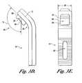
- FIG. 3Ais aside view of the clamp member of the invention as shown in FIGS. 1 and 2 embodied having an elongated finger with a crooked jaw portion extending therefrom and including an inclined clamping surface;
- FIG. 3Bis an end view of the clamp member of the invention as embodied in FIG. 3A;
- FIG. 3Cshows a bottom end view of the clamp member of the invention alternatively embodied using a tongue-and-groove structure for mating with the respective body portions of the invention
- FIG. 3Dis a side view of the clamp member of the invention embodied in a simpler shape as compared with that shown in FIGS. 3A and 3B, wherein the clamp member is formed having a single bend between the base portion and the inclined clamping surface, but is otherwise substantially as shown in FIGS. 3A and 3B; and
- FIG. 3Eis an end view of the alternative clamp member of the invention embodied as shown in FIG. 3 D.
- FIG. 1illustrates the invention embodied as a mounting platform 10 for various vehicle-mounted, after-market accessory devices, such as a portable computer (shown), a cellular telephone, a global positioning system (GPS) receiver, or another useful accessory device.
- the mounting platform 10includes a first frame or body portion 12 having an interior track 14 aligned along a first direction 16 and a first device mounting surface 18 adjacent to the track 14 .
- a second frame or body portion 20includes a second device mounting surface 22 adjacent to a slide 24 structured to slidably engage the track 14 along the first direction 16 .
- a resilient membershown in FIG.
- At least one clamp member 26is mounted on each of the first and second body portions 12 , 20 in a manner projecting above the respective first and second device mounting surfaces 18 , 22 .
- Each clamp member 26includes a clamping surface 28 facing toward the respective first and second body portions 12 , 20 along the first direction 16 and being inclined relative to the respective first and second device mounting surfaces 18 , 22 .
- Multiple clamp members 26are optionally provided, as shown, on one or both of the first and second body portions 12 , 20 .
- a substantially thin, flat base portion of the accessory deviceengages the first and second device mounting surfaces 18 , 22 of the first and second body portions 12 , 20 . Thereafter, the inclined clamping surfaces 28 of the clamp members 26 engage opposing edges of an upper surface of the base portion of the accessory device that is spaced away from the device mounting surfaces 18 , 22 .
- the resilient member urging the first and second body portions 12 , 20 to approach one another along the first direction 16simultaneously urges the clamp members 26 to approach one another along the first direction 16 such that the inclined clamping surfaces 28 press on the opposing edges of the base portion upper surface to compress the upper surface of the accessory device downwardly toward the device mounting surfaces 18 , 22 , as indicated by the arrows 29 .
- the device mounting surfaces 18 , 22are equipped with a relatively high coefficient of friction that operates in combination with the pressure applied by the inclined clamping surfaces 28 of the clamp members 26 to limit slippage of the accessory device relative to the device mounting surfaces 18 , 22 .
- one or more stops 30are fixed to respective side surfaces 32 , 34 of the first and second body portions 12 , 20 in a manner projecting above the respective first and second device mounting surfaces 18 , 22 .
- the optional stop or stops 30are useful for positioning the accessory device relative to the device mounting surfaces 18 , 22 .
- the optional stop or stops 30add protection against slippage of the accessory device relative to the device mounting surfaces 18 , 22 when the device mounting surfaces 18 , 22 are tilted so that gravity would urge the accessory device to slip off of the device mounting surfaces 18 , 22 .
- a mounting structure 36is positioned on one of the first and second body portions 12 , 20 for engaging a mounting device (not shown) in or on the vehicle.
- the mounting structure 36is, for example, the compressible coupling member portion of the universally positionable mounting device shown and described in U.S. Pat. No. 5,845,885 issued to the inventor of the present invention on Dec. 8, 1998, which is incorporated in its entirety herein by reference, and the mounting device is the one shown and described in therein.
- the mounting structure 36is, for example, the geodesic coupler shown and described in application Ser. No.
- FIG. 2is an exploded view of the mounting platform 10 as shown in FIG. 1 .
- a portion 38 of the first device mounting surface 18 of the first body portion 12is equipped with a relatively high coefficient of friction.
- the high friction portion 38is a pad of material having a relatively high coefficient of friction.
- a thin rubber sheetis adhered to the first device mounting surface 18 , either with a suitable adhesive therebetween or using another conventional mechanical adhesion means.
- the high friction portion 38is a sheet of conventional non-skid material, such as sand paper, adhered to the first device mounting surface 18 .
- the high friction portion 38 of the first device mounting surface 18is formed with a grooved, knurled, serrated, slotted, or otherwise suitably roughened surface area in place of the rubber sheet or non-skid material.
- the track 14is shown in FIG. 2 embodied as a cavity 40 adjacent to the first device mounting surface 18 .
- the cavity 40includes an opening 42 thereinto and four interior planar surfaces 44 , 46 , 48 , 50 , each of the pairs of opposing interior surfaces 44 , 48 and 46 , 50 being mutually parallel and spaced apart and interconnected at the edges to the other respective pair.
- the four interior planar surfaces 44 , 46 , 48 , 50thus form two mutually parallel and spaced apart channel-shaped tracks 14 a and 14 b , the first channel-shaped track 14 a being formed of the interior surface 46 and portions of the mutually parallel and spaced apart interior surfaces 44 , 48 interconnected thereto at the edges, and the second channel-shaped track 14 b being formed of the interior surface 50 and portions of the mutually parallel and spaced apart interior surfaces 44 , 48 interconnected thereto at the edges.
- the second body portion 20is a drawer-like structure having the second device mounting surface 22 adjacent to the slide 24 , which is embodied as a pair of slides 24 a and 24 b .
- the pair of slides 24 a and 24 bare structured to enter the cavity 40 in the first body portion 12 through the opening 42 , and to slidably engage the tracks 14 a and 14 b , respectively, along the first direction 16 .
- the pair of slides 24 a and 24 bare structured with sufficient stiffness or rigidity to support a portion of the weight of the accessory device on the second device mounting surface 22 , while projecting in a cantilevered manner from the respective mating tracks 14 a and 14 b .
- the pair of slides 24 a and 24 bare optionally integrally formed with a base portion 52 and the second device mounting surface 22 formed thereon.
- the slides 24 a , 24 b and tracks 14 a , 14 bare optionally formed differently from the embodiment shown in FIG. 2 .
- the slides 24 a , 24 bare optionally formed as rods or tubes that slidably engage tracks 14 a , 14 b formed as mating tubular structures.
- the track 14 and slide 24 structureis formed as a conventional telescoping rod-and-tube structure of a type that is well-known in the mechanical arts.
- Other mating track-and-slide structuresare generally well-known and are considered to be equivalents of the track 14 and slide 24 structure shown.
- FIG. 2also illustrates the resilient member for urging the first and second body portions 12 , 20 to approach one another along the first direction 16 , wherein the resilient member is embodied as a spring 54 .
- the spring 54is a tension spring coupled by conventional means at opposing ends to appropriate structure formed on each of the first and second body portions 12 , 20 .
- the spring 54resists the separating force by increasing the spring tension force and thereby urges the first and second body portions 12 , 20 back together.
- the cooperating track 14 and slide 24 structuresensure that relative motion between the first and second body portions 12 , 20 is limited to motion along the first direction 16 .
- the tension force of spring 54also brings the clamp members 26 into engagement with opposing upper surface edges of the base portion of the accessory device that is placed on the device mounting surfaces 18 , 22 .
- the respective end faces 56 , 58 of the first and second body portions 12 , 20are structured for mounting one or more of the clamp members 26 .
- the end faces 56 , 58are formed with apertures 60 sized to accept a fastener 62 , such as a screw or bolt and nut combination, for mounting each of the one or more of the clamp members 26 .
- the respective end faces 56 , 58 of the first and second body portions 12 , 20are optionally formed with a relatively high friction surface area, such as a grooved, knurled, diamond, serrated, slotted, or otherwise suitably roughened surface area, that provides purchase for the one or more clamp members 26 .
- the high friction surfacepermits each of the clamp members 26 to be positioned on the respective end faces 56 , 58 while removing any opportunity for them to shift position.
- the first and second body portions 12 , 20can be separated and accessory device inserted and remove multiple times without readjustment of the clamp members 26 .
- FIGS. 3A and 3Billustrate the clamp member 26 as an elongated finger having a base portion 64 with a mounting surface 66 and a crooked jaw portion 68 extending therefrom.
- FIG. 3Ais a side view of the clamp member 26
- FIG. 3Bis an end view thereof.
- the jaw portion 68includes a curved neck portion 70 extending from the base portion 64 into a short straight portion 72 having the inclined clamping surface 28 formed as facet thereof.
- the straight portion 72is formed at an appropriate predetermined obtuse angle 74 to the base portion 64 .
- the angle 74is about 135 degrees according to one embodiment of the invention, but according to other embodiments of the invention can optionally vary +or ⁇ 15 degrees or more.
- the jaw portion 68When the clamp member 26 is installed on the end faces 56 , 58 of the first and second body portions 12 , 20 , the jaw portion 68 extends above the respective first and second device mounting surfaces 18 , 22 .
- the angle 74positions the short straight portion 72 of the jaw portion 68 with the inclined clamping surface 28 facing inwardly and downwardly toward the respective first and second device mounting surfaces 18 , 22 .
- the angle 74permits the jaw portions 68 to engage the upper edges of the accessory device along the entire length of the inclined clamping surface 28 so that devices having base portions of different thicknesses are easily accommodated, without adjustments in the positions of the clamp members 26 relative to the device mounting surfaces 18 , 22 .
- the mounting surface 66 of the base portion 64 of each clamp member 26is embodied having a relatively high friction surface, such as a grooved, knurled, diamond, serrated, slotted, or otherwise suitably roughened surface area, that is configured to cooperate with the high friction surface area formed on the respective end faces 56 , 58 to eliminate slippage of the clamp member 26 relative to the respective end faces 56 , 58 .
- the high friction mounting surface 66is a grooved surface when the cooperating high friction surface area on the end faces 56 , 58 of the respective body portions 12 , 20 are grooved surfaces.
- each clamp member 26is optionally embodied having a stiffener portion 76 extending along part or all of its length for strengthening the clamp member 26 in the plane of the first direction 16 in which the clamping surface 28 acts.
- FIG. 3Aalso shows that the mounting surface 66 of the base portion 64 is optionally embodied with threaded stud 78 that passes through one of the apertures 60 (shown in FIG. 2 ), thereby replacing the fastener 62 for mounting the clamp member 26 .
- the apertures 60are embodied as slots in the end faces 56 , 58 of the body portions 12 , 20 , whereby the clamp member 26 is selectively positionable relative to the respective body portions 12 , 20 by moving the threaded stud 78 to different positions within the slot 60 .
- the clamp member 26is captured and held in place by engagement of a nut (not shown) onto the threaded stud 78 after it is passed through the slot 60 and selectively positioned relative to one of the respective end faces 56 , 58 .
- each clamp member 26includes an aperture 80 sized to accept the fastener 62 for fixing the clamp member 26 to one of the end faces 56 , 58 .
- the aperture 80is embodied as a slot aligned with the length of the base portion 64 so that the clamp member 26 can be moved relative to the body portions 12 , 20 , whereby the jaw portion 68 is spaced further away from or closer to the first and second device mounting surfaces 18 , 22 .
- the optional ability to move the clamp member 26 relative to the body portions 12 , 20thus accommodates accessory devices with base portions having a wider range of thicknesses.
- FIG. 3Cshows a bottom end view of the clamp member 26 alternatively embodied using a tongue-and-groove structure for mating with the respective body portions 12 , 20 .
- the clamp member 26is formed with an optional T-shaped flange 82 for joining with a cooperating slot structure 84 formed in the end faces 56 , 58 .
- the clamp member 26is thus capable of movement, i.e., adjustment, relative to the first and second device mounting surfaces 18 , 22 for accommodating accessory devices with base portions having a wider range of thicknesses.
- FIG. 3Dshows the clamp member 26 embodied in a simpler shape having a single bend 86 between the base portion 64 and the short straight portion 72 of the jaw portion 68 , but is otherwise substantially as described above.
- the single bend 86is formed at the appropriate predetermined angle 74 , which is again about 135 degrees according to one embodiment of the invention.
- the short straight portion 72 of the jaw portion 68is positioned by the angle 74 to face inwardly and downwardly toward the respective device mounting surfaces 18 , 22 , and permits the jaw portion 68 to engage accessory devices having base portions of different thicknesses, without adjustments in the positions of the clamp members 26 relative to the device mounting surfaces 18 , 22 .
- FIG. 3Eis an end view of the alternative clamp member 26 shown in FIG. 3 D and shows the high friction mounting surface 66 of the base portion 64 as a grooved surface that is interrupted by the slot 80 .
- the clamp member 26 as shown in FIGS. 3A through 3Eis formed with an optional width W that can be as to merely accommodate a single slot 80 or T-shaped flange 82 and a minimal amount of material on either side thereof.
- the inventionalso contemplates a clamp member 26 having an optionally greater width W that, for example, is contiguous with a large portion or substantially all of the width of the end faces 56 , 58 of the respective body portions 12 , 20 and accommodates multiple slots 80 or T-shaped flanges 82 .
- all such optional structuresare considered to be equivalents of the clamp member 26 of the invention.
- the clamp member 26includes the inclined clamping surface 28 , which is rotated at the angle 74 from the base portion 64 , as described above.
- the inclined clamping surfaces 28includes a portion 88 that is equipped with a relatively high coefficient of friction so that the clamping surface 28 grips the edge of the accessory device, rather than just compressing the accessory device into the device mounting surfaces 18 , 22 .
- the high friction portion 88is a pad of material having a relatively high coefficient of friction, such as a thin sheet of rubber or conventional non-skid material adhered to the inclined clamping surface 28 .
- the high friction portion 88is formed with a grooved, knurled, serrated, slotted, or otherwise suitably roughened surface area in place of the rubber sheet or non-skid material.
- the high friction portion 88is embodied as a resilient cushion or pressure pad formed of an elastomeric material, such as rubber or a synthetic substitute.
- the pressure pad 88is formed having a thickness and durometer that permits it to be compressed against the edge of the accessory device while remaining elastic.
- the pressure pad 88thus operates as a spring compressed between the clamping surface 28 and the accessory device to maintain a substantial spring pressure against the accessory device. This spring pressure operates to press the press the accessory device against the device mounting surfaces 18 , 22 , thereby further limiting slippage of the device resulting from the jarring experienced during motion of the vehicle.
- the pressure pad 88optionally includes a contact surface 90 that is equipped with a relatively high coefficient of friction so that the pressure pad 88 grips the edge of the accessory device, rather than just compressing the accessory device into the device mounting surfaces 18 , 22 .
- the high friction contact surface 90is formed with a grooved, knurled, serrated, slotted, or otherwise suitably roughened surface area or is covered with a thin sheet of rubber or another non-skid material.
Landscapes
- Engineering & Computer Science (AREA)
- Mechanical Engineering (AREA)
- Clamps And Clips (AREA)
Abstract
Description
Claims (33)
Priority Applications (1)
| Application Number | Priority Date | Filing Date | Title |
|---|---|---|---|
| US09/933,171US6585212B2 (en) | 2001-08-20 | 2001-08-20 | Quick release electronics platform |
Applications Claiming Priority (1)
| Application Number | Priority Date | Filing Date | Title |
|---|---|---|---|
| US09/933,171US6585212B2 (en) | 2001-08-20 | 2001-08-20 | Quick release electronics platform |
Publications (2)
| Publication Number | Publication Date |
|---|---|
| US20030034429A1 US20030034429A1 (en) | 2003-02-20 |
| US6585212B2true US6585212B2 (en) | 2003-07-01 |
Family
ID=25463496
Family Applications (1)
| Application Number | Title | Priority Date | Filing Date |
|---|---|---|---|
| US09/933,171Expired - LifetimeUS6585212B2 (en) | 2001-08-20 | 2001-08-20 | Quick release electronics platform |
Country Status (1)
| Country | Link |
|---|---|
| US (1) | US6585212B2 (en) |
Cited By (101)
| Publication number | Priority date | Publication date | Assignee | Title |
|---|---|---|---|---|
| US20040007651A1 (en)* | 2002-04-24 | 2004-01-15 | Innovative Office Products, Inc. | Universal support for electronic devices |
| US20040026590A1 (en)* | 2002-08-12 | 2004-02-12 | Chin-Chih Lin | Mobile computer rack |
| US20040075282A1 (en)* | 2002-10-19 | 2004-04-22 | Ira Silverman | Computer quick release latch |
| US20050045788A1 (en)* | 2003-08-28 | 2005-03-03 | Mongeau Adam David | Mount for an input device |
| US20050092877A1 (en)* | 2003-10-31 | 2005-05-05 | Carnevali Jeffrey D. | Configurable mounting apparatus |
| US20050205730A1 (en)* | 2004-03-17 | 2005-09-22 | Carnevali Jeffrey D | Configurable mounting bracket |
| US20050205724A1 (en)* | 2004-03-17 | 2005-09-22 | Carnevali Jeffrey D | Configurable mounting bracket |
| WO2005089136A2 (en) | 2004-03-17 | 2005-09-29 | Carnevali Jeffrey D | Configurable mounting bracket |
| US7032872B2 (en)* | 2002-05-22 | 2006-04-25 | Gamber Johnson Llc | Universal laptop computer mount |
| US20060161713A1 (en)* | 2005-01-20 | 2006-07-20 | Belady Christian L | Mounting a computer in a transport vehicle |
| US20060171045A1 (en)* | 2005-01-28 | 2006-08-03 | Carnevali Jeffrey D | Intermediately mounted magnification apparatus |
| US20060169608A1 (en)* | 2005-01-28 | 2006-08-03 | Carnevali Jeffrey D | Dry box with protective cover |
| US20060169689A1 (en)* | 2005-01-28 | 2006-08-03 | Carnevali Jeffrey D | Sealed window for dry box |
| US20060233601A1 (en)* | 2005-04-15 | 2006-10-19 | Crain Stephen B | Coupler for a mount system |
| US20060231714A1 (en)* | 2005-04-15 | 2006-10-19 | Crain Stephen B | Clamp for mount system |
| US20060231713A1 (en)* | 2005-04-15 | 2006-10-19 | Crain Stephen B | Mount system for handheld electrical device |
| US20060285306A1 (en)* | 2005-05-24 | 2006-12-21 | Carnevali Jeffrey D | Secure universal mounting apparatus |
| US20070018067A1 (en)* | 2005-07-25 | 2007-01-25 | Askey Computer Corp. | Electronic device holder |
| US20070045503A1 (en)* | 2005-08-26 | 2007-03-01 | Samari Badiollah R | Book holder |
| USD558771S1 (en) | 2006-06-09 | 2008-01-01 | Innovative Office Products, Inc. | Laptop holder |
| US20080029663A1 (en)* | 2006-08-04 | 2008-02-07 | Innovative Office Products, Inc. | Laptop holder for extension arm |
| US20080035823A1 (en)* | 2003-08-27 | 2008-02-14 | Rossini Alfred P | Laptop Computer Stand |
| US20080115344A1 (en)* | 2004-06-30 | 2008-05-22 | Carnevali Jeffrey D | Configurable mounting apparatus |
| US20080252045A1 (en)* | 2007-04-11 | 2008-10-16 | Rossini Alfred P | Single-Post, Height Adjustable Cart |
| US20080296821A1 (en)* | 2007-05-31 | 2008-12-04 | Carnevali Jeffrey D | Quick release electronics platform |
| US20080296449A1 (en)* | 2007-05-31 | 2008-12-04 | Carnevali Jeffrey D | Quick release electronics platform |
| US20090127418A1 (en)* | 2007-11-21 | 2009-05-21 | Chia-Ming Wang | Computer dock station |
| US20090212189A1 (en)* | 2007-05-31 | 2009-08-27 | Carnevali Jeffrey D | Quick release electronics platform |
| US20090315287A1 (en)* | 2008-06-20 | 2009-12-24 | Rossini Alfred P | Mobile Cart |
| US20100004535A1 (en)* | 2008-07-03 | 2010-01-07 | Medison Co., Ltd. | Dual keyboard input device and movable cart having the same mounted thereon |
| US20100001149A1 (en)* | 2008-07-03 | 2010-01-07 | Mi Ran Song | Medical instrument |
| US20100012796A1 (en)* | 2003-08-27 | 2010-01-21 | Rossini Alfred P | Mobile Cart Laptop Computer Retainer and Stand System |
| US20100038505A1 (en)* | 2008-08-18 | 2010-02-18 | Juliet Sonnenberg | Portable object support |
| US20100181450A1 (en)* | 2009-01-16 | 2010-07-22 | Troy Hulick | Accessory attachment mechanism |
| US20100195278A1 (en)* | 2009-01-31 | 2010-08-05 | Eran Wilkenfeld | Electronic Device Support System |
| US20100301183A1 (en)* | 2009-05-29 | 2010-12-02 | Carnevali Jeffrey D | Side arm clamp assembly |
| US7886903B1 (en) | 2008-09-19 | 2011-02-15 | Aileron Designs, LLC | Articulated notebook computer cover and mounting device |
| US20110062299A1 (en)* | 2009-09-16 | 2011-03-17 | Wen-Feng Tsai | Car computer/LCD monitor holder |
| US7911779B1 (en) | 2009-09-30 | 2011-03-22 | L&P Property Management Company | Computer docking station |
| US20110101058A1 (en)* | 2009-05-28 | 2011-05-05 | Tom Heckman | Pivot mount assembly |
| US20110140381A1 (en)* | 2008-06-20 | 2011-06-16 | Jaco, Inc. | Mobile Cart Base with Traction Wheel |
| US7978466B2 (en) | 2008-02-27 | 2011-07-12 | L&P Property Management Company | Computer docking station for a vehicle |
| US20120012579A1 (en)* | 2010-07-15 | 2012-01-19 | Kemal Kaya Kaplancali | Device cover |
| US20120018595A1 (en)* | 2010-07-21 | 2012-01-26 | James Berry | Holding device for an electronic device |
| US20120127651A1 (en)* | 2010-11-23 | 2012-05-24 | Kitae Kwon | Systems and Methods for Securing Mobile Computing Devices |
| US8235334B1 (en)* | 2011-02-16 | 2012-08-07 | Mark Kobal | Tablet computer holder and support |
| US8308114B2 (en) | 2009-02-25 | 2012-11-13 | Tensolite LLC | Electronic flight bag mounting bracket |
| US20130048821A1 (en)* | 2011-07-15 | 2013-02-28 | Patrick John Leet | Sporting Gear Storage System |
| US20130075544A1 (en)* | 2011-09-26 | 2013-03-28 | Li-Wei Liu | Supporting apparatus |
| US8439698B1 (en) | 2010-06-15 | 2013-05-14 | Amrinder Pal Singh Saini | Low profile mechanical and electrical accessory connector |
| JP2013131007A (en)* | 2011-12-21 | 2013-07-04 | Nec Access Technica Ltd | Integrated component and product using the same |
| US20130263494A1 (en)* | 2012-04-06 | 2013-10-10 | Daniel Kay | Rodent trap mounting member and method |
| US20140042285A1 (en)* | 2012-08-13 | 2014-02-13 | Jeffrey D. Carnevali | Modular electronics platform |
| US8763848B2 (en)* | 2011-05-20 | 2014-07-01 | Bf Gate Mate Inc. | Container for a tailgate party |
| US8867202B2 (en) | 2011-08-23 | 2014-10-21 | L&P Property Management Company | Docking station |
| US8929065B2 (en) | 2011-08-23 | 2015-01-06 | L&P Property Management Company | Docking station with ruggedized case |
| US9010537B2 (en) | 2010-11-04 | 2015-04-21 | Jeffrey D. Carnevali | Protective enclosure for touch screen device |
| US20150197177A1 (en)* | 2014-01-14 | 2015-07-16 | Timothy Dean Eyler | Equipment Docking Apparatus |
| US9132787B2 (en) | 2011-03-01 | 2015-09-15 | L&P Property Management Company | Keyboard mounting apparatus |
| US9195279B2 (en) | 2014-02-24 | 2015-11-24 | National Products, Inc. | Docking sleeve with electrical adapter |
| US9331444B2 (en) | 2014-02-24 | 2016-05-03 | National Products, Inc. | Docking sleeve with electrical adapter |
| WO2016076921A1 (en)* | 2014-11-13 | 2016-05-19 | Pajic Nick | Electronic device support for vehicles |
| US9403596B2 (en)* | 2011-10-13 | 2016-08-02 | SmartTray International, LLC | Tray table with rotatable inner tray and adjustable retention assembly |
| US20160223004A1 (en)* | 2015-01-30 | 2016-08-04 | Alcatel - Lucent Canada, Inc. | Unit locking system and method |
| US9529387B2 (en) | 2014-02-24 | 2016-12-27 | National Products, Inc. | Docking sleeve with electrical adapter |
| US9602639B2 (en) | 2014-02-24 | 2017-03-21 | National Products, Inc. | Docking sleeve with electrical adapter |
| US9651994B1 (en)* | 2016-02-02 | 2017-05-16 | Infiniwing, Inc. | Docking station with anti-theft mechanism for portable electronic device |
| US9674975B2 (en) | 2005-01-28 | 2017-06-06 | Jeffrey D. Carnevali | Protective enclosure for touch screen device |
| US9706026B2 (en) | 2014-02-24 | 2017-07-11 | National Products, Inc. | Docking sleeve with electrical adapter |
| US20170210301A1 (en)* | 2015-08-17 | 2017-07-27 | Havis, Inc. | Keyboard mounting system |
| US9831904B1 (en) | 2016-12-14 | 2017-11-28 | National Products, Inc. | Adjustable cradle for mobile devices and methods of making and using |
| US9833064B2 (en) | 2015-07-23 | 2017-12-05 | Gamber-Johnson Llc | Keyboard mounting assembly |
| US10050658B2 (en) | 2014-02-24 | 2018-08-14 | National Products, Inc. | Docking sleeve with electrical adapter |
| US20180231034A1 (en)* | 2017-02-10 | 2018-08-16 | Panasonic Intellectual Property Management Co., Ltd. | Module attachment device |
| US10061354B2 (en) | 2016-10-14 | 2018-08-28 | Gamber-Johnson Llc | Docking station for electronic device |
| US10150395B2 (en) | 2011-10-13 | 2018-12-11 | SmartTray International, LLC | Electronic device support for vehicles |
| US10323785B1 (en)* | 2017-05-19 | 2019-06-18 | Yoshio Takahashi | Tablet holder |
| US10401905B2 (en) | 2016-06-27 | 2019-09-03 | National Products, Inc. | Slide dock and methods of making and using |
| US10427619B2 (en) | 2011-10-13 | 2019-10-01 | SmartTray International, LLC | Electronic device support for vehicles |
| US10464459B2 (en) | 2011-10-13 | 2019-11-05 | SmartTray International, LLC | Tray table with electronic device support for vehicles |
| US10679679B1 (en)* | 2018-12-21 | 2020-06-09 | Seagate Technology Llc | Slider test socket with clamp, and related assemblies and methods of use |
| US10812643B1 (en) | 2020-05-04 | 2020-10-20 | National Products, Inc. | Cases for mobile devices incorporating a light within the case and methods of making and using |
| US10917981B2 (en)* | 2019-05-30 | 2021-02-09 | Aplex Technology Inc. | Adjustable embedded display unit backframe |
| US10976777B2 (en) | 2019-08-15 | 2021-04-13 | Gamber-Johnson Llc | Docking station |
| US11029731B1 (en) | 2020-04-20 | 2021-06-08 | National Products, Inc. | Cradles and cases for mobile devices incorporating guide elements or modular components and methods of making and using |
| CN113167432A (en)* | 2018-12-21 | 2021-07-23 | 松下知识产权经营株式会社 | Electronic equipment holding structure and electronic equipment holding device |
| US11076032B1 (en) | 2020-05-26 | 2021-07-27 | National Products, Inc. | Cradles for mobile devices with a plunger lock and methods of making and using |
| US11277506B2 (en) | 2020-05-26 | 2022-03-15 | National Products, Inc. | Cradles for mobile devices with one or more biasing tabs and methods of making and using |
| US11289864B2 (en) | 2020-04-20 | 2022-03-29 | National Products, Inc. | Cases for mobile devices with a flexible covering and rigid frame or with two different connector arrangements and methods of making and using |
| US11313434B2 (en)* | 2020-06-30 | 2022-04-26 | Rolls-Royce North American Technologies, Inc. | Shock absorption bracket |
| US11345414B1 (en)* | 2021-11-22 | 2022-05-31 | Super ATV, LLC | Vehicle accessory clamp |
| US11489350B2 (en) | 2019-12-23 | 2022-11-01 | National Products, Inc. | Cradle for mobile devices with resilient guides and methods of making and using |
| US11619343B2 (en) | 2020-06-23 | 2023-04-04 | Otter Products, Llc | Multi-function controller mount |
| US11652326B2 (en) | 2021-04-30 | 2023-05-16 | National Products, Inc. | Dock with flexible locator pins and methods of making and using |
| US11654351B2 (en) | 2020-06-23 | 2023-05-23 | Otter Products, Llc | Multi-function controller mount |
| US11728846B1 (en) | 2022-10-13 | 2023-08-15 | National Products, Inc. | Remote repeater device for mobile device dock and methods of making and using |
| US20240188733A1 (en)* | 2022-12-12 | 2024-06-13 | Prolifico Llc | Record holder |
| US12126199B2 (en) | 2021-08-09 | 2024-10-22 | National Products, Inc. | Cradles for a mobile device including a cavity for a wireless device and methods of making and using |
| US12158776B2 (en) | 2022-04-25 | 2024-12-03 | National Products, Inc. | Docks for mobile devices with simultaneous data transfer and charging and systems and methods using the docks |
| US12298809B2 (en) | 2023-07-05 | 2025-05-13 | National Products, Inc. | Heating module for electronic device dock and methods of making and using |
| US12362527B2 (en) | 2020-06-10 | 2025-07-15 | National Products, Inc. | Cases for mobile devices incorporating a cord extending from the case and methods of making and using |
Families Citing this family (8)
| Publication number | Priority date | Publication date | Assignee | Title |
|---|---|---|---|---|
| US7658363B2 (en)* | 2006-06-20 | 2010-02-09 | Meyer Christopher E | Laptop security device for technology workstand |
| US7828253B2 (en)* | 2006-06-20 | 2010-11-09 | Meyer Christopher E | Secure shelf for technology workstand |
| GB2440339A (en)* | 2006-07-21 | 2008-01-30 | Artform Internat Ltd | Means for securing an electrical device |
| US7866623B2 (en)* | 2008-10-21 | 2011-01-11 | Sony Corporation | Computer retail display stand |
| US20150292669A1 (en)* | 2014-04-14 | 2015-10-15 | Engineered Network Systems | Lockable Tablet Stand |
| CA3052210A1 (en)* | 2017-03-09 | 2018-09-13 | Ergotron, Inc. | Flexible retention systems for portable electronic devices |
| US10279753B1 (en)* | 2017-11-03 | 2019-05-07 | Ford Global Technologies, Llc | Retractable electronic device holder |
| DE112021001056T5 (en)* | 2020-04-28 | 2023-02-02 | Fanuc Corporation | SAFETY SWITCHING DEVICE |
Citations (21)
| Publication number | Priority date | Publication date | Assignee | Title |
|---|---|---|---|---|
| US1670970A (en)* | 1926-12-23 | 1928-05-22 | Tilton & Cook Co | Barrette |
| US1684925A (en)* | 1927-03-14 | 1928-09-18 | Artistic Brass & Bronze Works | Adjustable base |
| US2653330A (en)* | 1951-09-27 | 1953-09-29 | Nolan Charles | Seat-attached bassinet |
| US2733492A (en)* | 1956-02-07 | Clasp for holding articles | ||
| US3581424A (en)* | 1969-06-11 | 1971-06-01 | Ben P Bloom | Fisherman{3 s dekinker |
| US3669392A (en)* | 1969-09-10 | 1972-06-13 | William C Saunders | Collapsible stand-up tray holder |
| US4066231A (en) | 1975-08-25 | 1978-01-03 | Bahner Randal E | Locking stand for small, portable devices |
| US4118003A (en)* | 1976-12-22 | 1978-10-03 | Dillow Paul E | Radio antenna mounting device |
| US4798294A (en)* | 1987-08-31 | 1989-01-17 | North American Philips Corp | Shipping tray assembly for an article having casters |
| US4802708A (en)* | 1987-04-15 | 1989-02-07 | Wilbur Vos | Removable boat seat |
| US4844387A (en)* | 1986-12-31 | 1989-07-04 | Hunt Holdings, Inc. | Monitor arm apparatus |
| US4909159A (en)* | 1988-11-25 | 1990-03-20 | Don Gonsoulin | Automobile computer desk |
| US4957264A (en)* | 1989-02-08 | 1990-09-18 | Nokia-Mobira Oy | Mounting base for a telephone device, such as a mobile telephone |
| US5024408A (en)* | 1990-04-30 | 1991-06-18 | Maynard Magee | Athletic shoe holder |
| US5149032A (en)* | 1990-11-29 | 1992-09-22 | Jones Stephen W | Universal cup holder for use in vehicles |
| US5612509A (en)* | 1994-04-29 | 1997-03-18 | Market; Roger | Stackable wire staple and raceway system |
| US5653414A (en)* | 1995-11-20 | 1997-08-05 | Chimel; Richard A. | Clip for holding eyeglasses |
| US5673628A (en)* | 1995-12-12 | 1997-10-07 | Boos; Shane M. | Table for supporting and securing a portable computer in a vehicle |
| US5793614A (en)* | 1996-09-03 | 1998-08-11 | Tektronix, Inc. | Injector/ejector for electronic module housing |
| US6213438B1 (en)* | 1999-12-16 | 2001-04-10 | Ostby Leroy M. | Computer support for vehicle use having multiple position adjustments |
| US6286797B1 (en)* | 1999-09-21 | 2001-09-11 | Rocky A. Thaxton | Illumination assembly |
- 2001
- 2001-08-20USUS09/933,171patent/US6585212B2/ennot_activeExpired - Lifetime
Patent Citations (21)
| Publication number | Priority date | Publication date | Assignee | Title |
|---|---|---|---|---|
| US2733492A (en)* | 1956-02-07 | Clasp for holding articles | ||
| US1670970A (en)* | 1926-12-23 | 1928-05-22 | Tilton & Cook Co | Barrette |
| US1684925A (en)* | 1927-03-14 | 1928-09-18 | Artistic Brass & Bronze Works | Adjustable base |
| US2653330A (en)* | 1951-09-27 | 1953-09-29 | Nolan Charles | Seat-attached bassinet |
| US3581424A (en)* | 1969-06-11 | 1971-06-01 | Ben P Bloom | Fisherman{3 s dekinker |
| US3669392A (en)* | 1969-09-10 | 1972-06-13 | William C Saunders | Collapsible stand-up tray holder |
| US4066231A (en) | 1975-08-25 | 1978-01-03 | Bahner Randal E | Locking stand for small, portable devices |
| US4118003A (en)* | 1976-12-22 | 1978-10-03 | Dillow Paul E | Radio antenna mounting device |
| US4844387A (en)* | 1986-12-31 | 1989-07-04 | Hunt Holdings, Inc. | Monitor arm apparatus |
| US4802708A (en)* | 1987-04-15 | 1989-02-07 | Wilbur Vos | Removable boat seat |
| US4798294A (en)* | 1987-08-31 | 1989-01-17 | North American Philips Corp | Shipping tray assembly for an article having casters |
| US4909159A (en)* | 1988-11-25 | 1990-03-20 | Don Gonsoulin | Automobile computer desk |
| US4957264A (en)* | 1989-02-08 | 1990-09-18 | Nokia-Mobira Oy | Mounting base for a telephone device, such as a mobile telephone |
| US5024408A (en)* | 1990-04-30 | 1991-06-18 | Maynard Magee | Athletic shoe holder |
| US5149032A (en)* | 1990-11-29 | 1992-09-22 | Jones Stephen W | Universal cup holder for use in vehicles |
| US5612509A (en)* | 1994-04-29 | 1997-03-18 | Market; Roger | Stackable wire staple and raceway system |
| US5653414A (en)* | 1995-11-20 | 1997-08-05 | Chimel; Richard A. | Clip for holding eyeglasses |
| US5673628A (en)* | 1995-12-12 | 1997-10-07 | Boos; Shane M. | Table for supporting and securing a portable computer in a vehicle |
| US5793614A (en)* | 1996-09-03 | 1998-08-11 | Tektronix, Inc. | Injector/ejector for electronic module housing |
| US6286797B1 (en)* | 1999-09-21 | 2001-09-11 | Rocky A. Thaxton | Illumination assembly |
| US6213438B1 (en)* | 1999-12-16 | 2001-04-10 | Ostby Leroy M. | Computer support for vehicle use having multiple position adjustments |
Non-Patent Citations (1)
| Title |
|---|
| U.S. application Ser. No. 08/920,847 filed Aug. 29, 1997 having priority date Jun. 28, 1994, allowed Sep. 9, 1998. |
Cited By (169)
| Publication number | Priority date | Publication date | Assignee | Title |
|---|---|---|---|---|
| US20040007651A1 (en)* | 2002-04-24 | 2004-01-15 | Innovative Office Products, Inc. | Universal support for electronic devices |
| US7032872B2 (en)* | 2002-05-22 | 2006-04-25 | Gamber Johnson Llc | Universal laptop computer mount |
| US20040026590A1 (en)* | 2002-08-12 | 2004-02-12 | Chin-Chih Lin | Mobile computer rack |
| US6817587B2 (en)* | 2002-08-12 | 2004-11-16 | Chin-Chih Lin | Mobile computer rack |
| US20040075282A1 (en)* | 2002-10-19 | 2004-04-22 | Ira Silverman | Computer quick release latch |
| US6814377B2 (en)* | 2002-10-19 | 2004-11-09 | Fujitsu Limited | Computer quick release latch |
| US20100012796A1 (en)* | 2003-08-27 | 2010-01-21 | Rossini Alfred P | Mobile Cart Laptop Computer Retainer and Stand System |
| US20080035823A1 (en)* | 2003-08-27 | 2008-02-14 | Rossini Alfred P | Laptop Computer Stand |
| US7611119B2 (en)* | 2003-08-27 | 2009-11-03 | Rossini Alfred P | Laptop computer stand |
| US20050045788A1 (en)* | 2003-08-28 | 2005-03-03 | Mongeau Adam David | Mount for an input device |
| US20050092877A1 (en)* | 2003-10-31 | 2005-05-05 | Carnevali Jeffrey D. | Configurable mounting apparatus |
| US7320450B2 (en) | 2003-10-31 | 2008-01-22 | Carnevali Jeffrey D | Configurable mounting apparatus |
| US20050205724A1 (en)* | 2004-03-17 | 2005-09-22 | Carnevali Jeffrey D | Configurable mounting bracket |
| US7959116B2 (en) | 2004-03-17 | 2011-06-14 | Carnevali Jeffrey D | Configurable mounting bracket |
| WO2005089136A2 (en) | 2004-03-17 | 2005-09-29 | Carnevali Jeffrey D | Configurable mounting bracket |
| US20050205730A1 (en)* | 2004-03-17 | 2005-09-22 | Carnevali Jeffrey D | Configurable mounting bracket |
| US20080115344A1 (en)* | 2004-06-30 | 2008-05-22 | Carnevali Jeffrey D | Configurable mounting apparatus |
| US20060161713A1 (en)* | 2005-01-20 | 2006-07-20 | Belady Christian L | Mounting a computer in a transport vehicle |
| US20060171045A1 (en)* | 2005-01-28 | 2006-08-03 | Carnevali Jeffrey D | Intermediately mounted magnification apparatus |
| US7464814B2 (en) | 2005-01-28 | 2008-12-16 | Carnevali Jeffrey D | Dry box with movable protective cover |
| US7850032B2 (en) | 2005-01-28 | 2010-12-14 | Carnevali Jeffrey D | Sealed window for dry box |
| US7277240B2 (en) | 2005-01-28 | 2007-10-02 | Carnevali Jeffrey D | Intermediately mounted magnification apparatus |
| US20110049175A1 (en)* | 2005-01-28 | 2011-03-03 | Carnevali Jeffrey D | Sealed window for dry box |
| US9674975B2 (en) | 2005-01-28 | 2017-06-06 | Jeffrey D. Carnevali | Protective enclosure for touch screen device |
| US20060169608A1 (en)* | 2005-01-28 | 2006-08-03 | Carnevali Jeffrey D | Dry box with protective cover |
| US8701912B2 (en) | 2005-01-28 | 2014-04-22 | National Products, Inc. | Sealed window for dry box |
| US20060169689A1 (en)* | 2005-01-28 | 2006-08-03 | Carnevali Jeffrey D | Sealed window for dry box |
| US20060231714A1 (en)* | 2005-04-15 | 2006-10-19 | Crain Stephen B | Clamp for mount system |
| US20060233601A1 (en)* | 2005-04-15 | 2006-10-19 | Crain Stephen B | Coupler for a mount system |
| US7669816B2 (en) | 2005-04-15 | 2010-03-02 | Seco Manufacturing Company, Inc. | Clamp for mount system |
| US20060231713A1 (en)* | 2005-04-15 | 2006-10-19 | Crain Stephen B | Mount system for handheld electrical device |
| US7441981B2 (en) | 2005-04-15 | 2008-10-28 | Crain Enterprises, Inc. | Coupler for a mount system |
| US8490937B2 (en) | 2005-04-15 | 2013-07-23 | Seco Manufacturing Company, Inc. | Mount system for handheld electrical device |
| US20060285306A1 (en)* | 2005-05-24 | 2006-12-21 | Carnevali Jeffrey D | Secure universal mounting apparatus |
| US7551458B2 (en) | 2005-05-24 | 2009-06-23 | Carnevali Jeffrey D | Secure universal mounting apparatus |
| US20070018067A1 (en)* | 2005-07-25 | 2007-01-25 | Askey Computer Corp. | Electronic device holder |
| US7540464B2 (en)* | 2005-08-26 | 2009-06-02 | Badiollah R. Samari | Book holder |
| US20070045503A1 (en)* | 2005-08-26 | 2007-03-01 | Samari Badiollah R | Book holder |
| USD558771S1 (en) | 2006-06-09 | 2008-01-01 | Innovative Office Products, Inc. | Laptop holder |
| US20080029663A1 (en)* | 2006-08-04 | 2008-02-07 | Innovative Office Products, Inc. | Laptop holder for extension arm |
| US7922137B2 (en) | 2006-08-04 | 2011-04-12 | Innovative Office Products, Inc. | Laptop holder for extension arm |
| US20080252045A1 (en)* | 2007-04-11 | 2008-10-16 | Rossini Alfred P | Single-Post, Height Adjustable Cart |
| US8091850B2 (en) | 2007-05-31 | 2012-01-10 | Carnevali Jeffrey D | Quick release electronics platform |
| US20090212189A1 (en)* | 2007-05-31 | 2009-08-27 | Carnevali Jeffrey D | Quick release electronics platform |
| US8074951B2 (en) | 2007-05-31 | 2011-12-13 | Carnevali Jeffrey D | Quick release electronics platform |
| US20080296821A1 (en)* | 2007-05-31 | 2008-12-04 | Carnevali Jeffrey D | Quick release electronics platform |
| US7823844B2 (en) | 2007-05-31 | 2010-11-02 | Carnevali Jeffrey D | Quick release electronics platform |
| US20080296449A1 (en)* | 2007-05-31 | 2008-12-04 | Carnevali Jeffrey D | Quick release electronics platform |
| US20090127418A1 (en)* | 2007-11-21 | 2009-05-21 | Chia-Ming Wang | Computer dock station |
| US7918427B2 (en)* | 2007-11-21 | 2011-04-05 | Sallas Industrial Co., Ltd. | Computer dock station |
| US7978466B2 (en) | 2008-02-27 | 2011-07-12 | L&P Property Management Company | Computer docking station for a vehicle |
| US8098488B2 (en) | 2008-02-27 | 2012-01-17 | L&P Property Management Company | Computer docking station for a vehicle |
| USRE43869E1 (en) | 2008-02-27 | 2012-12-25 | L&P Property Management Company | Computer docking station for a vehicle |
| US20110140381A1 (en)* | 2008-06-20 | 2011-06-16 | Jaco, Inc. | Mobile Cart Base with Traction Wheel |
| US20090315287A1 (en)* | 2008-06-20 | 2009-12-24 | Rossini Alfred P | Mobile Cart |
| US8567798B2 (en) | 2008-06-20 | 2013-10-29 | Jaco, Inc. | Mobile cart base with traction wheel |
| US20100004535A1 (en)* | 2008-07-03 | 2010-01-07 | Medison Co., Ltd. | Dual keyboard input device and movable cart having the same mounted thereon |
| US20100001149A1 (en)* | 2008-07-03 | 2010-01-07 | Mi Ran Song | Medical instrument |
| US7806376B2 (en)* | 2008-07-03 | 2010-10-05 | Medison Co., Ltd. | Medical instrument |
| US20100038505A1 (en)* | 2008-08-18 | 2010-02-18 | Juliet Sonnenberg | Portable object support |
| US7886903B1 (en) | 2008-09-19 | 2011-02-15 | Aileron Designs, LLC | Articulated notebook computer cover and mounting device |
| US9370114B1 (en) | 2009-01-16 | 2016-06-14 | Amazon Technologies, Inc. | Accessory attachment mechanism |
| US20100181450A1 (en)* | 2009-01-16 | 2010-07-22 | Troy Hulick | Accessory attachment mechanism |
| US8511633B2 (en)* | 2009-01-16 | 2013-08-20 | Amazon Technologies, Inc. | Accessory attachment mechanism |
| US20100195278A1 (en)* | 2009-01-31 | 2010-08-05 | Eran Wilkenfeld | Electronic Device Support System |
| US8199490B2 (en)* | 2009-01-31 | 2012-06-12 | Eran Wilkenfeld | Electronic device support system |
| US8308114B2 (en) | 2009-02-25 | 2012-11-13 | Tensolite LLC | Electronic flight bag mounting bracket |
| US20110101058A1 (en)* | 2009-05-28 | 2011-05-05 | Tom Heckman | Pivot mount assembly |
| US8201788B2 (en)* | 2009-05-29 | 2012-06-19 | Carnevali Jeffrey D | Side arm clamp assembly |
| US20100301183A1 (en)* | 2009-05-29 | 2010-12-02 | Carnevali Jeffrey D | Side arm clamp assembly |
| US20110062299A1 (en)* | 2009-09-16 | 2011-03-17 | Wen-Feng Tsai | Car computer/LCD monitor holder |
| US10481636B2 (en) | 2009-09-30 | 2019-11-19 | Gamber-Johnson Llc | Computer docking station |
| US8315048B2 (en) | 2009-09-30 | 2012-11-20 | L&P Property Management Company | Computer docking station |
| US9612616B2 (en) | 2009-09-30 | 2017-04-04 | Gamber-Johnson Llc | Computer docking station |
| US9964992B2 (en) | 2009-09-30 | 2018-05-08 | Gamber-Johnson Llc | Computer docking station |
| US20110134602A1 (en)* | 2009-09-30 | 2011-06-09 | Tarnoff Matthew S | Computer docking station |
| US20110075351A1 (en)* | 2009-09-30 | 2011-03-31 | Tarnoff Matthew S | Computer docking station |
| US7911779B1 (en) | 2009-09-30 | 2011-03-22 | L&P Property Management Company | Computer docking station |
| US8439698B1 (en) | 2010-06-15 | 2013-05-14 | Amrinder Pal Singh Saini | Low profile mechanical and electrical accessory connector |
| US20120012579A1 (en)* | 2010-07-15 | 2012-01-19 | Kemal Kaya Kaplancali | Device cover |
| US8646736B2 (en)* | 2010-07-21 | 2014-02-11 | James Berry | Holding device for an electronic device |
| US20120018595A1 (en)* | 2010-07-21 | 2012-01-26 | James Berry | Holding device for an electronic device |
| US9010537B2 (en) | 2010-11-04 | 2015-04-21 | Jeffrey D. Carnevali | Protective enclosure for touch screen device |
| US8649169B2 (en)* | 2010-11-23 | 2014-02-11 | Infiniwing, Inc. | Systems and methods for securing mobile computing devices |
| US20120127651A1 (en)* | 2010-11-23 | 2012-05-24 | Kitae Kwon | Systems and Methods for Securing Mobile Computing Devices |
| US20120205503A1 (en)* | 2011-02-16 | 2012-08-16 | Mark Kobal | Tablet Computer Holder and Support |
| US8235334B1 (en)* | 2011-02-16 | 2012-08-07 | Mark Kobal | Tablet computer holder and support |
| US9132787B2 (en) | 2011-03-01 | 2015-09-15 | L&P Property Management Company | Keyboard mounting apparatus |
| US8763848B2 (en)* | 2011-05-20 | 2014-07-01 | Bf Gate Mate Inc. | Container for a tailgate party |
| US9038976B2 (en)* | 2011-07-15 | 2015-05-26 | Patrick John Leet | Sporting gear storage system |
| US20130048821A1 (en)* | 2011-07-15 | 2013-02-28 | Patrick John Leet | Sporting Gear Storage System |
| US8929065B2 (en) | 2011-08-23 | 2015-01-06 | L&P Property Management Company | Docking station with ruggedized case |
| US9310841B2 (en) | 2011-08-23 | 2016-04-12 | L&P Property Management Company | Docking station with ruggedized case |
| US8867202B2 (en) | 2011-08-23 | 2014-10-21 | L&P Property Management Company | Docking station |
| US9098239B2 (en) | 2011-08-23 | 2015-08-04 | L&P Property Management Company | Docking station with ruggedized case |
| US8789800B2 (en)* | 2011-09-26 | 2014-07-29 | Wistron Corporation | Supporting apparatus |
| US20130075544A1 (en)* | 2011-09-26 | 2013-03-28 | Li-Wei Liu | Supporting apparatus |
| US10427619B2 (en) | 2011-10-13 | 2019-10-01 | SmartTray International, LLC | Electronic device support for vehicles |
| US10464459B2 (en) | 2011-10-13 | 2019-11-05 | SmartTray International, LLC | Tray table with electronic device support for vehicles |
| US9403596B2 (en)* | 2011-10-13 | 2016-08-02 | SmartTray International, LLC | Tray table with rotatable inner tray and adjustable retention assembly |
| US10150395B2 (en) | 2011-10-13 | 2018-12-11 | SmartTray International, LLC | Electronic device support for vehicles |
| JP2013131007A (en)* | 2011-12-21 | 2013-07-04 | Nec Access Technica Ltd | Integrated component and product using the same |
| US8959829B2 (en)* | 2012-04-06 | 2015-02-24 | Daniel Kay | Rodent trap mounting member and method |
| US20130263494A1 (en)* | 2012-04-06 | 2013-10-10 | Daniel Kay | Rodent trap mounting member and method |
| US20140042285A1 (en)* | 2012-08-13 | 2014-02-13 | Jeffrey D. Carnevali | Modular electronics platform |
| US9776577B2 (en)* | 2012-08-13 | 2017-10-03 | Jeffrey D. Carnevali | Modular electronics platform |
| US20150197177A1 (en)* | 2014-01-14 | 2015-07-16 | Timothy Dean Eyler | Equipment Docking Apparatus |
| US10207626B2 (en)* | 2014-01-14 | 2019-02-19 | Timothy Dean Eyler | Equipment docking apparatus |
| US10389399B2 (en) | 2014-02-24 | 2019-08-20 | National Products, Inc. | Docking sleeve with electrical adapter |
| US11165458B2 (en) | 2014-02-24 | 2021-11-02 | National Products, Inc. | Docking sleeve with electrical adapter |
| US11476884B2 (en) | 2014-02-24 | 2022-10-18 | National Products, Inc. | Docking sleeve with electrical adapter |
| US12132511B2 (en) | 2014-02-24 | 2024-10-29 | National Products, Inc. | Docking sleeve with electrical adapter |
| US12143141B2 (en) | 2014-02-24 | 2024-11-12 | National Products, Inc. | Docking sleeve with electrical adapter |
| US12143142B2 (en) | 2014-02-24 | 2024-11-12 | National Products, Inc. | Docking sleeve with electrical adapter |
| US9954330B2 (en) | 2014-02-24 | 2018-04-24 | National Products, Inc. | Docking sleeve with electrical adapter |
| US9632535B2 (en) | 2014-02-24 | 2017-04-25 | National Products, Inc. | Docking sleeve with electrical adapter |
| US10050658B2 (en) | 2014-02-24 | 2018-08-14 | National Products, Inc. | Docking sleeve with electrical adapter |
| US12143140B2 (en) | 2014-02-24 | 2024-11-12 | National Products, Inc. | Docking sleeve with electrical adapter |
| US10054984B2 (en) | 2014-02-24 | 2018-08-21 | National Products, Inc. | Docking sleeve with electrical adapter |
| US9706026B2 (en) | 2014-02-24 | 2017-07-11 | National Products, Inc. | Docking sleeve with electrical adapter |
| US12341550B2 (en) | 2014-02-24 | 2025-06-24 | National Products, Inc. | Docking sleeve with electrical adapter |
| US9602639B2 (en) | 2014-02-24 | 2017-03-21 | National Products, Inc. | Docking sleeve with electrical adapter |
| US9529387B2 (en) | 2014-02-24 | 2016-12-27 | National Products, Inc. | Docking sleeve with electrical adapter |
| US10778275B2 (en) | 2014-02-24 | 2020-09-15 | National Products, Inc. | Docking sleeve with electrical adapter |
| US10666309B2 (en) | 2014-02-24 | 2020-05-26 | National Products, Inc. | Docking sleeve with electrical adapter |
| US10630334B2 (en) | 2014-02-24 | 2020-04-21 | National Products, Inc. | Docking sleeve with electrical adapter |
| US9195279B2 (en) | 2014-02-24 | 2015-11-24 | National Products, Inc. | Docking sleeve with electrical adapter |
| US10454515B2 (en) | 2014-02-24 | 2019-10-22 | National Products, Inc. | Docking sleeve with electrical adapter |
| US9331444B2 (en) | 2014-02-24 | 2016-05-03 | National Products, Inc. | Docking sleeve with electrical adapter |
| WO2016076921A1 (en)* | 2014-11-13 | 2016-05-19 | Pajic Nick | Electronic device support for vehicles |
| US20160223004A1 (en)* | 2015-01-30 | 2016-08-04 | Alcatel - Lucent Canada, Inc. | Unit locking system and method |
| US9833064B2 (en) | 2015-07-23 | 2017-12-05 | Gamber-Johnson Llc | Keyboard mounting assembly |
| US10144361B2 (en)* | 2015-08-17 | 2018-12-04 | Havis, Inc. | Keyboard mounting system |
| US20170210301A1 (en)* | 2015-08-17 | 2017-07-27 | Havis, Inc. | Keyboard mounting system |
| US9651994B1 (en)* | 2016-02-02 | 2017-05-16 | Infiniwing, Inc. | Docking station with anti-theft mechanism for portable electronic device |
| US10401905B2 (en) | 2016-06-27 | 2019-09-03 | National Products, Inc. | Slide dock and methods of making and using |
| US10061354B2 (en) | 2016-10-14 | 2018-08-28 | Gamber-Johnson Llc | Docking station for electronic device |
| US9831904B1 (en) | 2016-12-14 | 2017-11-28 | National Products, Inc. | Adjustable cradle for mobile devices and methods of making and using |
| US10704576B2 (en)* | 2017-02-10 | 2020-07-07 | Panasonic Intellectual Property Management Co., Ltd. | Module attachment device |
| US20180231034A1 (en)* | 2017-02-10 | 2018-08-16 | Panasonic Intellectual Property Management Co., Ltd. | Module attachment device |
| US10323785B1 (en)* | 2017-05-19 | 2019-06-18 | Yoshio Takahashi | Tablet holder |
| JPWO2020129595A1 (en)* | 2018-12-21 | 2021-11-04 | パナソニックIpマネジメント株式会社 | Electronic device holding structure and electronic device holding device |
| US11705162B2 (en) | 2018-12-21 | 2023-07-18 | Seagate Technology Llc | Slider test clamp, and related assemblies and methods of use |
| US20210285477A1 (en)* | 2018-12-21 | 2021-09-16 | Panasonic Intellectual Property Management Co., Ltd. | Electronic device retaining structure and electronic device retaining device |
| US11195559B2 (en) | 2018-12-21 | 2021-12-07 | Seagate Technology Llc | Slider test socket with clamp, and related assemblies and methods of use |
| CN113167432A (en)* | 2018-12-21 | 2021-07-23 | 松下知识产权经营株式会社 | Electronic equipment holding structure and electronic equipment holding device |
| US10679679B1 (en)* | 2018-12-21 | 2020-06-09 | Seagate Technology Llc | Slider test socket with clamp, and related assemblies and methods of use |
| US12014754B2 (en) | 2018-12-21 | 2024-06-18 | Seagate Technology Llc | Clamp for removably holding a slider, and related assemblies and methods of use |
| CN113167432B (en)* | 2018-12-21 | 2023-12-01 | 松下知识产权经营株式会社 | Electronic device holding structure and electronic device holding device |
| US11789495B2 (en)* | 2018-12-21 | 2023-10-17 | Panasonic Intellectual Property Management Co., Ltd. | Electronic device retaining structure and electronic device retaining device |
| US10917981B2 (en)* | 2019-05-30 | 2021-02-09 | Aplex Technology Inc. | Adjustable embedded display unit backframe |
| US10976777B2 (en) | 2019-08-15 | 2021-04-13 | Gamber-Johnson Llc | Docking station |
| US11489350B2 (en) | 2019-12-23 | 2022-11-01 | National Products, Inc. | Cradle for mobile devices with resilient guides and methods of making and using |
| US11029731B1 (en) | 2020-04-20 | 2021-06-08 | National Products, Inc. | Cradles and cases for mobile devices incorporating guide elements or modular components and methods of making and using |
| US11289864B2 (en) | 2020-04-20 | 2022-03-29 | National Products, Inc. | Cases for mobile devices with a flexible covering and rigid frame or with two different connector arrangements and methods of making and using |
| US10812643B1 (en) | 2020-05-04 | 2020-10-20 | National Products, Inc. | Cases for mobile devices incorporating a light within the case and methods of making and using |
| US11076032B1 (en) | 2020-05-26 | 2021-07-27 | National Products, Inc. | Cradles for mobile devices with a plunger lock and methods of making and using |
| US11277506B2 (en) | 2020-05-26 | 2022-03-15 | National Products, Inc. | Cradles for mobile devices with one or more biasing tabs and methods of making and using |
| US12362527B2 (en) | 2020-06-10 | 2025-07-15 | National Products, Inc. | Cases for mobile devices incorporating a cord extending from the case and methods of making and using |
| US11619343B2 (en) | 2020-06-23 | 2023-04-04 | Otter Products, Llc | Multi-function controller mount |
| US11654351B2 (en) | 2020-06-23 | 2023-05-23 | Otter Products, Llc | Multi-function controller mount |
| US11313434B2 (en)* | 2020-06-30 | 2022-04-26 | Rolls-Royce North American Technologies, Inc. | Shock absorption bracket |
| US11652326B2 (en) | 2021-04-30 | 2023-05-16 | National Products, Inc. | Dock with flexible locator pins and methods of making and using |
| US12126199B2 (en) | 2021-08-09 | 2024-10-22 | National Products, Inc. | Cradles for a mobile device including a cavity for a wireless device and methods of making and using |
| US11345414B1 (en)* | 2021-11-22 | 2022-05-31 | Super ATV, LLC | Vehicle accessory clamp |
| US12158776B2 (en) | 2022-04-25 | 2024-12-03 | National Products, Inc. | Docks for mobile devices with simultaneous data transfer and charging and systems and methods using the docks |
| US11728846B1 (en) | 2022-10-13 | 2023-08-15 | National Products, Inc. | Remote repeater device for mobile device dock and methods of making and using |
| US20240188733A1 (en)* | 2022-12-12 | 2024-06-13 | Prolifico Llc | Record holder |
| US12298809B2 (en) | 2023-07-05 | 2025-05-13 | National Products, Inc. | Heating module for electronic device dock and methods of making and using |
Also Published As
| Publication number | Publication date |
|---|---|
| US20030034429A1 (en) | 2003-02-20 |
Similar Documents
| Publication | Publication Date | Title |
|---|---|---|
| US6585212B2 (en) | Quick release electronics platform | |
| US7647676B2 (en) | Thumb release mounting apparatus | |
| US8176603B2 (en) | Universal cradle apparatus | |
| US7837166B2 (en) | Monitor clamping device | |
| US6966533B1 (en) | Mounting apparatus for an electronic device | |
| US6955280B2 (en) | Cellular phone securing device and onboard holder for vehicle use | |
| US8201788B2 (en) | Side arm clamp assembly | |
| US5979724A (en) | Automobile universal dashboard mounting apparatus | |
| US10011005B2 (en) | Bar clamp | |
| US7571522B2 (en) | Quick draw cradle apparatus | |
| US20210194256A1 (en) | Cradle for mobile devices with resilient guides and methods of making and using | |
| US20100038505A1 (en) | Portable object support | |
| WO2004034871A3 (en) | Stabilized table (12) rail (14) clamp | |
| US20060026807A1 (en) | Quick release mounting apparatus | |
| JP2581435B2 (en) | Holding devices such as mobile phones | |
| JPH01176984U (en) | ||
| US5861872A (en) | Adjustable mounting for a pointing device | |
| JPH074541Y2 (en) | Tissue embedding cassette mounting table for microtome | |
| JP2002019535A (en) | Mounting device for in-vehicle imaging machine | |
| US20230365059A1 (en) | Auxiliary mirror fastening device | |
| US20250240364A1 (en) | Adjustable mobile device holder | |
| JPS6257290A (en) | Rail mounting apparatus for electric equipment | |
| JPH0529165Y2 (en) | ||
| JPH0112465Y2 (en) | ||
| JPH07217611A (en) | Supporting table for electronic apparatus |
Legal Events
| Date | Code | Title | Description |
|---|---|---|---|
| STCF | Information on status: patent grant | Free format text:PATENTED CASE | |
| CC | Certificate of correction | ||
| FEPP | Fee payment procedure | Free format text:PAT HOLDER CLAIMS SMALL ENTITY STATUS, ENTITY STATUS SET TO SMALL (ORIGINAL EVENT CODE: LTOS); ENTITY STATUS OF PATENT OWNER: SMALL ENTITY | |
| FPAY | Fee payment | Year of fee payment:4 | |
| REMI | Maintenance fee reminder mailed | ||
| REMI | Maintenance fee reminder mailed | ||
| FPAY | Fee payment | Year of fee payment:8 | |
| SULP | Surcharge for late payment | Year of fee payment:7 | |
| FPAY | Fee payment | Year of fee payment:12 | |
| AS | Assignment | Owner name:NATIONAL PRODUCTS INC, UNITED STATES Free format text:NUNC PRO TUNC ASSIGNMENT;ASSIGNOR:CARNEVALI, JEFFREY D;REEL/FRAME:037302/0672 Effective date:20151215 | |
| IPR | Aia trial proceeding filed before the patent and appeal board: inter partes review | Free format text:TRIAL NO: IPR2016-01663 Opponent name:ARKON RESOURCES, INC. Effective date:20160825 | |
| AS | Assignment | Owner name:NATIONAL PRODUCTS, INC., WASHINGTON Free format text:ASSIGNMENT OF ASSIGNORS INTEREST;ASSIGNOR:CARNEVALI, JEFFREY D.;REEL/FRAME:046393/0262 Effective date:20180614 | |
| IPR | Aia trial proceeding filed before the patent and appeal board: inter partes review | Free format text:TRIAL NO: IPR2020-01542 Opponent name:SCANSTRUT, LTD.,SCANSTRUT, INC., SCANSTRUT (HOLDINGS) LTD., AND LIFEDGE LTD. Effective date:20200828 |