US6584977B1 - Combined patient interface and exhaust assembly - Google Patents
Combined patient interface and exhaust assemblyDownload PDFInfo
- Publication number
- US6584977B1 US6584977B1US09/824,291US82429101AUS6584977B1US 6584977 B1US6584977 B1US 6584977B1US 82429101 AUS82429101 AUS 82429101AUS 6584977 B1US6584977 B1US 6584977B1
- Authority
- US
- United States
- Prior art keywords
- patient
- patient interface
- faceplate
- exhaust
- exhaust path
- Prior art date
- Legal status (The legal status is an assumption and is not a legal conclusion. Google has not performed a legal analysis and makes no representation as to the accuracy of the status listed.)
- Expired - Fee Related, expires
Links
Images


Classifications
- A—HUMAN NECESSITIES
- A61—MEDICAL OR VETERINARY SCIENCE; HYGIENE
- A61M—DEVICES FOR INTRODUCING MEDIA INTO, OR ONTO, THE BODY; DEVICES FOR TRANSDUCING BODY MEDIA OR FOR TAKING MEDIA FROM THE BODY; DEVICES FOR PRODUCING OR ENDING SLEEP OR STUPOR
- A61M16/00—Devices for influencing the respiratory system of patients by gas treatment, e.g. ventilators; Tracheal tubes
- A61M16/20—Valves specially adapted to medical respiratory devices
- A—HUMAN NECESSITIES
- A61—MEDICAL OR VETERINARY SCIENCE; HYGIENE
- A61M—DEVICES FOR INTRODUCING MEDIA INTO, OR ONTO, THE BODY; DEVICES FOR TRANSDUCING BODY MEDIA OR FOR TAKING MEDIA FROM THE BODY; DEVICES FOR PRODUCING OR ENDING SLEEP OR STUPOR
- A61M16/00—Devices for influencing the respiratory system of patients by gas treatment, e.g. ventilators; Tracheal tubes
- A61M16/06—Respiratory or anaesthetic masks
- A—HUMAN NECESSITIES
- A61—MEDICAL OR VETERINARY SCIENCE; HYGIENE
- A61M—DEVICES FOR INTRODUCING MEDIA INTO, OR ONTO, THE BODY; DEVICES FOR TRANSDUCING BODY MEDIA OR FOR TAKING MEDIA FROM THE BODY; DEVICES FOR PRODUCING OR ENDING SLEEP OR STUPOR
- A61M16/00—Devices for influencing the respiratory system of patients by gas treatment, e.g. ventilators; Tracheal tubes
- A61M16/08—Bellows; Connecting tubes ; Water traps; Patient circuits
- A61M16/0816—Joints or connectors
- A61M16/0825—Joints or connectors with ball-sockets
- A—HUMAN NECESSITIES
- A61—MEDICAL OR VETERINARY SCIENCE; HYGIENE
- A61M—DEVICES FOR INTRODUCING MEDIA INTO, OR ONTO, THE BODY; DEVICES FOR TRANSDUCING BODY MEDIA OR FOR TAKING MEDIA FROM THE BODY; DEVICES FOR PRODUCING OR ENDING SLEEP OR STUPOR
- A61M16/00—Devices for influencing the respiratory system of patients by gas treatment, e.g. ventilators; Tracheal tubes
- A61M16/06—Respiratory or anaesthetic masks
- A61M16/0683—Holding devices therefor
- A—HUMAN NECESSITIES
- A61—MEDICAL OR VETERINARY SCIENCE; HYGIENE
- A61M—DEVICES FOR INTRODUCING MEDIA INTO, OR ONTO, THE BODY; DEVICES FOR TRANSDUCING BODY MEDIA OR FOR TAKING MEDIA FROM THE BODY; DEVICES FOR PRODUCING OR ENDING SLEEP OR STUPOR
- A61M16/00—Devices for influencing the respiratory system of patients by gas treatment, e.g. ventilators; Tracheal tubes
- A61M16/08—Bellows; Connecting tubes ; Water traps; Patient circuits
- A61M16/0816—Joints or connectors
Definitions
- the present inventionpertains to a combined patient interface and integrated exhaust assembly, and, in particular, to such a combination in which the exhaust assembly provides a controlled flow of exhaust gas, such as a constant flow of gas, from the interior of the patient interface over a range of pressures within the patient interface relative to ambient atmosphere.
- a controlled flow of exhaust gassuch as a constant flow of gas
- Conventional exhaust assemblesare used, for example, to provide an exhaust flow path for exhaled air in a ventilation circuit, which supplies a continuous flow of breathing gas to a spontaneously breathing patient.
- a ventilation circuitwhich supplies a continuous flow of breathing gas to a spontaneously breathing patient.
- exhalation gasbackflows in the ventilation circuit and, unless exhausted from the circuit, can be rebreathed by the patient during the next inhalation phase.
- Rebreathing of exhaled gasis undesirable, of course, because the exhalation flow contains CO 2 .
- Reliable and thorough exhaustion or purging of exhalation gas from the ventilation circuitis, thus, an important feature of such ventilation circuits, which are also commonly referred as breathing circuits or patient circuits. This purging becomes a more difficult problem the further the exhalation valve is located from the patient interface, due to the amount of residual exhaled gas in the intervening ventilation circuit dead space.
- exhalation valvesprovide varying fluid flow at varying fluid pressures.
- the naturally occurring relationship of fluid flow rate to pressuremay be unacceptable in a ventilation circuit for a number of reasons.
- a fixed size leakespecially in single limb circuits, to flush away the gas that is exhaled by the patient into the breathing circuit before the exhaled gas can be rebreathed by the patient with the next inhalation.
- the fixed sized, i.e., fixed geometry or fixed orifice, leakmay be provided by an exhalation valve.
- an exhalation valve with a flow characteristic that varies naturally with pressure variations in the patient circuitmay not be suitable as a patient circuit exhaust valve.
- a fixed leakis more desirably one that provides a fixed flow rate, than one characterized by a flow path cross sectional area of fixed size.
- U.S. Pat. Nos. 5,685,296 and 5,937,855disclose a flow regulating valve that exhausts gas from a ventilation circuit at a constant flow rate despite varying pressure in the ventilation circuit.
- a positive pressure therapyis provided to the patient while he or she sleeps. Therefore, it is preferable for the patient circuit to be flexible and readily movable during the pressure support treatment. This goal may be frustrated by providing the exhaust valve on the patient circuit.
- the present inventioncontemplates a novel combination of a patient interface, such as a mask, and a flow control valve integrated with the mask and/or integrated with connection between the mask and the patient circuit.
- the flow control valveexhausts gas from the mask at a constant gas flow rate over a range of pressures within the interface. Because the valve is incorporated into the breathing mask or similar apparatus, which confronts the face of the patient, the amount of dead space in the patient circuit is minimized, and there is no excess material on the patient circuit that can hinder its performance or comfort.
- the patient interface assemblyincludes a faceplate having a first opening defined in a first end and a second opening defined in a second end thereof.
- a seal associated with the second openingis provided for contacting a surface of the patient, with the faceplate, seal, or both defining an interior of the patient interface assembly.
- a patient circuitis coupled to the first opening to communicate with an interior of the patient interface assembly.
- the exhaust assemblyis provided at the interconnection of the faceplate and patient circuit, and includes an exhaust path defined generally between the faceplate and the patient circuit and a flow regulating member.
- the exhaust assemblyis incorporated into the mask shell or faceplate itself with the exhaust path being defined between portions of the faceplate and between the flow regulating member and a portion of the faceplate.
- the flow regulating membercontrols the rate of flow of exhaust gas passing to atmosphere through the exhaust path by being deformed into the exhaust path varying degrees.
- the degree of deformation of the flow regulating member into the exhaust pathis based on a pressure in the interior of the patient interface assembly relative to ambient atmospheric pressure. More specifically, the flow regulating member responds to the different pressures applied to its opposite sides to vary the effective cross sectional area of the exhaust path. With relatively higher pressure within the patient interface relative to ambient atmosphere pressure, the flow regulating member flexes and deforms into the flow path, thereby narrowing the exhaust path and thus reducing its effective cross sectional area.
- the amount of narrowing of the exhaust pathvaries with variation in the elevated pressure within the patient interface. Higher pressures in the patient interface produce greater exhaust path area reduction and lower pressures produce smaller flow path area reduction.
- the flow rate of the exhaust gascan be kept substantially constant over these ranges of pressures in the patient circuit. Because the flow regulating member can flex to an infinite number of positions with incremental changes in the elevated gas pressure within the patient interface, the cross sectional area of the exhaust path can be any of a corresponding infinite number of values.
- Further objects of the present inventionare to provide a system and method for providing a supply of breathing gas to an airway of a patient that makes use of the combined patient interface and integrated exhaust assembly.
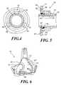
- FIG. 1is a side elevation of a patient interface and a connected gas supply circuit, partially sectioned to show the exhaust assembly according to a first embodiment of the present invention
- FIG. 2is an enlarged, sectional view of the first embodiment of the exhaust assembly of the present invention taken along lines II—II of FIG. 3;
- FIG. 3is an elevation of the exhaust assembly of FIGS. 1 and 2 shown from within the interior of the patient interface along lines III—III of FIG. 2, and with a portion of the flow regulating member broken away to reveal the valve porting;
- FIG. 4is an elevation of the valve of FIGS. 1 and 2 shown from outside the patient interface taken along lines IV—IV of FIG. 2;
- FIG. 5is a sectional view similar to FIG. 2 showing an alternative embodiment of exhaust assembly of the invention
- FIG. 6is a perspective view of a patient interface with another alternative embodiment of the exhaust assembly of the present invention.
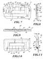
- FIG. 7is a fragmentary elevation view shown from within the patient interface of FIG. 6 showing the exhaust assembly of the FIG. 6 embodiment, with the flow regulating member partially broken away to reveal the valve porting;
- FIG. 8is a sectional view taken on lines VIII—VIII of FIG. 7;
- FIG. 9is a sectional view taken on lines IX—IX of FIG. 7;
- FIG. 10is an elevation view shown from outside of the patient interface of FIG. 6, along lines X—X of FIG. 8;
- FIG. 11is sectional view of a portion of a patient interface that includes yet another alternative embodiment of the exhaust assembly of the present invention.
- FIG. 12is a graph illustrating the exhaust flow through the exhaust assembly of FIGS. 1-3 versus the flow through the a conventional exhaust assembly.
- patient interface assembly 10for communicating a flow of breathing gas produced by a pressure generator 11 and carried by a patient circuit 12 to an airway of patient (not shown).
- patient interface assembly 10preferably comprises either a full or partial face mask 14 that fits over at least part of the patient's face, including the mouth, the nares, or both for communicating a flow of breathing gas from the gas source to an airway of a patient.
- patient interface assembly 10includes a faceplate 15 and a seal 13 for contacting the surface of the patient. Faceplate 15 , seal 13 , or both define an interior space 16 of mask 14 that receives the patient's nose or other facial features when the mask is donned by the patient.
- Faceplate 15is preferably, but not necessarily, a rigid material, such as plastic, and seal 13 , in this embodiment, is defined by flexible, relatively soft material to maximize patient comfort.
- the specific composition of faceplate 15 and seal 13are generally not relevant to the present invention so long as suitable materials that allow the invention to operate as described below are selected.
- Faceplateincludes a first opening 17 to which patient circuit 12 is attached, and a second opening 19 to which seal 13 is attached.
- seal 13 and faceplate 15are separate structures that are combined or joined during the manufacturing process to form patient interface assembly 10 .
- the present inventioncontemplates other structures for mask 14 , such as both faceplate 15 and seal 13 being made from like materials.
- a nasal mask or nasal/oral mask suitable for use with the present inventionwill have a seal portion that contacts the patient and a faceplate portion that carries the seal, with the exact structure, shape, and composition of the seal and faceplate not being particularly relevant to the present invention.
- breathing gasis directed from patient circuit 12 to interior space 16 via a suitable connecting element 18 .
- connecting elementis a 90° elbow that rotateably couples patient circuit 12 to faceplate 15 at a swivel connection 20 .
- Swivel connection 20allows free swiveling of connecting element 18 with respect to mask 14 about axis x—x. It is to be understood, however, that the present invention contemplates a variety of configurations for connecting element 18 , other than the 90° elbow shown in FIG. 1, such as an elbow of less than 90°.
- the present inventionalso contemplates coupling patient circuit 12 directly to mask 14 without connecting element 18 .
- a supply tube 22 of connecting element 18opens into interior space 16 of mask 14 .
- An external surface 24 of supply tube 22includes a reduced diameter cylindrical swivel bearing groove or recess portion 26 that extends circumferentially about tube 22 to form a bearing surface for swiveling engagement with mask faceplate 15 .
- the cooperating part of mask faceplate 15includes an outwardly projecting, generally tubular extension 28 , and a smaller diameter swivel bearing portion 30 , both of which coaxially enclose supply tube 22 .
- Swivel bearing portion 30includes a cylindrical swivel bearing surface 32 that cooperably engages cylindrical recess 26 , and is captured by axially opposed shoulders 27 formed at the opposed axial ends of recess 26 to thereby retain swivel bearing surfaces 26 and 32 in swiveling, mutually engaged relationship. Accordingly, connector element 18 is retained for free swiveling action about axis x—x with respect to faceplate 15 .
- An exhaust assembly, generally indicated at 33 , for venting gas from interior space 16 of patient interface assembly 10will now be described.
- An annular space 34is formed radially between tubular extension 28 and tube 22 , and extends axially between an inner end 36 , which opens to interior space 16 , and an outer end 38 located outside of the confines of faceplate 15 .
- Annular space 34thus defines a part of an exhaust path 44 between interior space 16 and the ambient atmosphere.
- annular space 34communicates with interior space 16 via a plurality of circumferentially spaced, radially outwardly projecting grooves 40 .
- annular space 34communicates with the ambient atmosphere via a plurality of circumferentially spaced exhaust openings 42 . See FIGS. 2 and 4.
- Exhaust openings 42preferably are located and configured to direct exhaust gas flow away from the face of the patient, to thereby minimize the discomfort of gas flow impinging on the patient's skin.
- Grooves 40 , annular space 34 , and exhaust openings 42together define exhaust path 44 through which gases exhaled by the patient, for example, are exhausted to the ambient atmosphere, rather than backflowing in patient circuit 12 and being subsequently rebreathed by the patient. Exhaust path 44 also serves to vent to ambient atmosphere excess gas delivered by the pressure generator.
- a unique, flow rate control functionis also provided to ensure an essentially constant exhaust flow rate through exhaust assembly 33 throughout a range of pressure differentials across the exhaust assembly, i.e., between interior space 16 and ambient atmosphere. Because the ambient pressure is constant for all practical purposes, a constant exhaust flow rate over a range of pressure differentials means essentially a constant exhaust flow rate over a range of pressures within patient interface assembly 10 . Such a range of pressures will routinely be observed in mask 14 , not only because patient breathing effort will generate pressure differences between inhalation and exhalation, but in addition because ventilation systems often are programmed to supply differing levels of pressure in coordination with the patient's breathing.
- pressure generator 11it is known to operate pressure generator 11 in a bilevel mode to deliver a high pressure to the patient during inspiration than during expiration. See, e.g., U.S. Pat. Nos. 5,148,802 and 5,443,193 the contents of which are hereby incorporated by reference into the present application.
- exhaust assembly 33includes a flow regulating member 46 which, in a preferred embodiment, is a resiliently deformable membrane, is provided within space 16 in an overlying relationship with grooves 40 .
- membrane 46is any one of a variety of deformable materials, such as silicone rubber, that enables the membrane to deform into exhaust path 44 so as to alter the effective area of the path.
- membrane 46includes a cylindrical portion 48 that is sealingly engaged in a circumferential recess 50 formed on the exterior, cylindrical surface 24 of supply tube 22 at a location spaced axially inward of recess 26 .
- annular flap portion 52 of membrane 46extends radially outward to a location just short of the radially outermost extent of grooves 40 , thus leaving a radially outermost terminal end portion 54 of each groove 40 that is not overlain by membrane 46 .
- the exposed ends 54 of grooves 40thus serve an inlet to exhaust path 44 for gas venting to atmosphere.
- the portions of flap 52 disposed circumferentially between adjacent grooves 40are supported on the corresponding intervening portions 56 of interior surface 41 of faceplate
- each groove in the exhaust patharc selected to provide the desired control over the flow rate of the exhaust path over the range of pressures in the patient circuit.
- the present inventioncontemplates that exhaust path cross sectional area diminishes and increases such that, in response to increasing and decreasing pressure differentials, respectively, the exhaust flow rate remains essentially constant over a range of expected ventilation circuit pressures.
- the specific configurations shown in the figuresare provided for illustration purposes and are not intended to be the only possible configuration for accomplishing this function.
- the present inventioncontemplates increasing or decreasing the number of grooves 40 defined in faceplate 15 .
- membranemay rotate with supply tube 22 as the connection element 18 swivels with respect to mask 14 . This will not effect operation of the described valving function since both the membrane 46 and the exhaust flow path, including grooves 40 , are symmetrically arranged about axis x—x.
- flow regulating member 46need not be formed from a unitary piece of material, but may be defined by a plurality of pieces of membrane material, each overlying a respective groove to provide the above-described flow regulating capability. Furthermore, piece of material can be coupled to faceplate 15 , rather than supply tube 22 , to allow supply tube 22 to rotate relative to mask 14 .
- connection of supply tube 22 to faceplate 15need not be a rotational connection.
- any one of a variety of techniquescan be used to interlock supply tube 22 to the faceplate and the flow regulating member can be provided on either the supply to of the faceplate. If a rotational capability is desired for patient circuit relative to the patient interface assembly, a rotational coupling can be provided in elsewhere in the patient circuit.
- the present inventioncontemplates controlling the flow rate of the exhaust gas over the range of operating pressures such that the flow rate is not necessarily constant. For example, it may be desirable that the flow rate of the exhaust gas decrease as the pressure in the patient circuit increases.
- the shape and size of the exhaust path and/or the shape, size, durometer, resiliency, elasticity or other properties of the flexible membranecan be selected to achieve such an exhaust gas flow rate versus patient circuit pressure relationship.
- FIG. 5illustrates an alternative embodiment of an exhaust assembly 33 ′ that is similar in all salient respects to exhaust assembly 33 of FIGS. 1-4, excepting only differences in the configuration of flow regulating member 46 ′ the structures of faceplate 14 ′ with which the flow regulating member cooperates.
- flow regulating member 46 ′is a resiliently deformable membrane that is disposed in overlying relationship with grooves 40 , as with the embodiment of FIGS. 1-4.
- Membrane 46 ′comprises a cylindrical portion 48 that is sealingly engaged in a circumferential recess 50 formed on the exterior, cylindrical surface 24 of supply tube 22 at a location spaced axially inward of swivel bearing recess 26 .
- annular flap portion 52 ′ of membrane 46 ′extends radially outward to a location just short of the radially outermost extent of grooves 40 ′, thus leaving a radially outermost terminal end portion 54 ′ of each groove 40 ′ that is not overlain by membrane 46 ′.
- the portions of flap 52 ′ disposed circumferentially between adjacent grooves 40 ′are supported on the corresponding intervening portions 56 ′ of the faceplate interior surface 17 ′.
- flap 52 ′is angled axially inward, that is to the left as viewed in FIG. 5, to form a shallow conical shape.
- Grooves 40 ′are similarly angled, as are the intervening surface portions 56 ′ of faceplate surface 41 ′.
- FIG. 5 embodimentis essentially the same as the FIG. 1-4 embodiment.
- the alternative membrane and groove geometry of FIG. 5is but one of any number of alternative configurations and structures that are intended to be included within the scope of the present invention.
- FIGS. 6-10A further alternative embodiment of an exhaust assembly 60 is shown in FIGS. 6-10.
- the exhaust assemblyfunctions as above described.
- the exhaust path and cooperating elementsare incorporated into faceplate 15 ′′ of patient interface assembly 10 ′, rather than in swivel connection 20 .
- patient interface assembly 10 ′includes a mask 14 ′′ coupled to a ventilator connection element 18 , which may be connected to mask 14 ′′ by a swivel connection 20 or by a fixed connection.
- Mask 14 ′′includes a faceplate 15 ′′ having an integral exhaust assembly 60 constructed into the faceplate, as described below with references to FIGS. 7-10.
- FIG. 7exhaust assembly 60 is shown as seen from the inside of mask 14 ′′.
- FIG. 8is a sectional view taken along line VIII—VIII of FIG. 7 showing the details of the exhaust assembly.
- the interior surface 41 ′′ of faceplate 15 ′′has formed therein a plurality of elongated grooves 40 ′′ disposed in spaced apart relationship.
- Each groove 40 ′′communicates with an elongated through opening 62 defined in faceplate 15 ′′, which communicates between the interior and the exterior of faceplate 15 ′′.
- grooves 40 ′′ and opening 62together define an exhaust path 44 ′′ (see FIG. 8) for venting gas, such as the patient's exhalation flow, to the ambient atmosphere.
- a flow regulating member 46 ′′ in the form of a resiliently flexible membraneoverlays opening 62 and a major portion of each groove 40 ′′, leaving a terminal end portion 54 ′′ of each groove 40 ′′ open to the interior of the mask. Between the grooves 40 ′′, membrane 46 ′′ overlies intervening portions 56 ′′ of surface 41 ′′.
- FIGS. 7-10An additional structural feature shown in FIGS. 7-10 is a shallow recess 64 formed in face plate interior surface 17 ′′ on a footprint that includes all of the described exhaust flow path except the terminal end portions 54 ′′ of grooves 40 ′′.
- the function of recess 64is to aid in controlling the resilient deformation of membrane 46 ′′ into grooves 40 ′′.
- a recess similar to recess 64may also be used with the FIG. 1-6 embodiments. It is thus another of a large variety of structural or geometric variations which are applicable for purposes of the invention.
- Membrane 46 ′′overlies recess 64 and is fixed to faceplate surface 41 ′′ by any suitable means, for example bonding thereof with adhesive placed outside the perimeter of recess 64 . Screws or other mechanical fasteners may also serve the purpose.
- the membranefunctions as above described with reference to the FIG. 1-6 embodiments to provide constant exhaust flow over a range of pressure differentials across the valve.
- exhaust assembly 60provides a constant flow rate or any predetermined relations for the flow rate of exhaust from the mask, thereby minimizing deadspace and optimizing the prevention of CO 2 rebreathing.
- exhaust assembly 60has no external bulges or protrusions that may hinder or impede the use of the breathing gas system.
- a variety of alternative configurationsare possible for the various components of exhaust assembly 60 .
- the number of grooves 40 ′′can be increased or decreased, the flow regulating member can be separated into individual elements associated with each groove, and multiple opening 62 can be provided.
- the present inventionfurther contemplates that one opening 62 can be provided for each groove 40 ′′.
- the shape and depth of grooves 40 ′′can be varied, as can the thickness, size, shape and material specification of the membrane 46 ′′.
- FIG. 11illustrates is sectional view of yet another embodiment of an exhaust assembly 66 for use in venting gas from an interior space 68 of patient interface to ambient atmosphere 70 through an exhaust path 72 , as indicated by arrows A.
- the flow regulating memberis a flexible membrane that deflects to control the size of the exhaust path as a function of the pressure within the patient interface.
- Exhaust assembly 66also includes a flow regulating member 74 .
- flow regulating member 74is defined, at least in part, by a relatively rigid member 76 in addition to a flexible member 78 that allows for movement of rigid member 76 .
- FIG. 11clarifies that the flow regulating member need not be formed entirely from a flexible membrane.
- the present inventioncontemplates a variety of techniques for controlling the size of the exhaust path based on the gas pressure within the patient interface to control the flow of gas from the patient circuit.
- flexible member 78 in FIG. 11can take the form of a spring, bellows, or any other member that provides a resiliently flexible characteristic, allowing a portion of the mask or vent assembly defining the exhaust path to move to control the cross-sectional area of the exhaust path as a function of the pressure in the patient interface.
- FIG. 12is a graph illustrating the exhaust flow through the exhaust assembly of FIGS. 1-3 versus the flow through the conventional exhaust assemblies.
- curve 90represents the flow of exhaust gas through exhaust assembly 33 of FIGS. 1-3.
- area 92the flow of gas through exhaust assembly 33 increases relatively smoothly as the pressure in interior space 16 increases and plateaus or level off, at area 94 so that the exhaust flow remains relatively constant even as the pressure increases. It can thus be appreciated that a relatively constant flow, i.e., ⁇ 2.5 liters per minute (1 pm), is maintained over a range of pressures, e.g. 7-22 cmH 2 O, by exhaust assembly 33 .
- Curve 96 in FIG. 12represents the flow of exhaust gas through the exhaust assembly taught by U.S. Pat. Nos. 5,685,296 and 5,937,855. Curve 96 also has a portion, indicated by area 94 , where the flow of exhausts gas from a ventilation circuit remains relatively constant flow despite varying pressure in the ventilation circuit. However, curve 96 , unlike curve 90 of the present invention, has a relatively abrupt change in flow over a relatively short change in pressure, as indicated by area 98 . In short, the patient experiences are relative rapid change in flow until plateau portion of the curve is reached. The exhaust assembly of the present invention, avoids this abrupt transition, and, thereby, maximizes patient comfort by providing the relatively smooth flow transition in area 92 until the plateau portion of curve 90 is reached.
- curve 100is also shown in FIG. 12, which corresponds to the flow of exhaust gas through a conventional, fixed orifice, exhaust path. It can be appreciated that curve 100 does not include an plateau region, because, being a fixed size orifice, the cross sectional area of the exhaust path does not change with changes in the pressure in the patient circuit.
Landscapes
- Health & Medical Sciences (AREA)
- Emergency Medicine (AREA)
- Pulmonology (AREA)
- Engineering & Computer Science (AREA)
- Anesthesiology (AREA)
- Biomedical Technology (AREA)
- Heart & Thoracic Surgery (AREA)
- Hematology (AREA)
- Life Sciences & Earth Sciences (AREA)
- Animal Behavior & Ethology (AREA)
- General Health & Medical Sciences (AREA)
- Public Health (AREA)
- Veterinary Medicine (AREA)
- Respiratory Apparatuses And Protective Means (AREA)
Abstract
Description
Claims (23)
Priority Applications (1)
| Application Number | Priority Date | Filing Date | Title |
|---|---|---|---|
| US09/824,291US6584977B1 (en) | 2000-04-06 | 2001-04-02 | Combined patient interface and exhaust assembly |
Applications Claiming Priority (2)
| Application Number | Priority Date | Filing Date | Title |
|---|---|---|---|
| US19502000P | 2000-04-06 | 2000-04-06 | |
| US09/824,291US6584977B1 (en) | 2000-04-06 | 2001-04-02 | Combined patient interface and exhaust assembly |
Publications (1)
| Publication Number | Publication Date |
|---|---|
| US6584977B1true US6584977B1 (en) | 2003-07-01 |
Family
ID=26890624
Family Applications (1)
| Application Number | Title | Priority Date | Filing Date |
|---|---|---|---|
| US09/824,291Expired - Fee RelatedUS6584977B1 (en) | 2000-04-06 | 2001-04-02 | Combined patient interface and exhaust assembly |
Country Status (1)
| Country | Link |
|---|---|
| US (1) | US6584977B1 (en) |
Cited By (87)
| Publication number | Priority date | Publication date | Assignee | Title |
|---|---|---|---|---|
| US20040216747A1 (en)* | 2003-02-28 | 2004-11-04 | Sunrise Medical Hhg Inc. | Nasal mask with lockable air inlet |
| WO2005021075A1 (en) | 2003-09-03 | 2005-03-10 | Fisher & Paykel Healthcare Limited | A mask |
| US20050268904A1 (en)* | 2004-06-07 | 2005-12-08 | Craig Corey | Device for delivering medication |
| US20060081250A1 (en)* | 2004-10-15 | 2006-04-20 | Bordewick Steven S | Nares seal |
| US20060096598A1 (en)* | 2004-11-05 | 2006-05-11 | Ho Peter C F | Respiratory mask seal and mask using same |
| USD535023S1 (en) | 2004-11-08 | 2007-01-09 | Resmed Limited | Elbow of a full face mask |
| US20070017522A1 (en)* | 2001-09-16 | 2007-01-25 | Eliezer Be-Eri | Inexsufflator |
| US20070144516A1 (en)* | 2005-12-08 | 2007-06-28 | Ric Investments, Llc. | Ventilator adaptable for use with either a dual-limb circuit or a single-limb circuit |
| US20070186928A1 (en)* | 2005-09-26 | 2007-08-16 | Be Eri Eliezer | Combined ventilator inexsufflator |
| US20070199566A1 (en)* | 2006-02-02 | 2007-08-30 | Be Eri Eliezer | Respiratory apparatus |
| WO2007102866A2 (en) | 2005-12-08 | 2007-09-13 | Ric Investments, Llc | Ventilator adaptable for use with either a dual-limb or a single-limb circuit |
| US20070240718A1 (en)* | 2006-04-17 | 2007-10-18 | Daly Robert W | Method and system for controlling breathing |
| US20080006275A1 (en)* | 2006-07-07 | 2008-01-10 | Steven Nickelson | Composite masks and methods for positive airway pressure therapies |
| WO2008100859A2 (en) | 2007-02-12 | 2008-08-21 | Ric Investments, Llc | Pressure support system and method with automatic comfort feature modification |
| USD580048S1 (en) | 2002-11-08 | 2008-11-04 | Resmed Limited | Swivel elbow for mask assembly |
| USD581041S1 (en) | 2002-08-09 | 2008-11-18 | Resmed Limited | Portion of a mask elbow |
| US20080302365A1 (en)* | 2007-06-08 | 2008-12-11 | Cohen Eric D | Respiratory Mask |
| US20090050156A1 (en)* | 2007-08-24 | 2009-02-26 | Resmed Limited | Mask vent |
| USD590496S1 (en) | 2004-05-17 | 2009-04-14 | Resmed Limited | Mask shell/assembly |
| US20090126731A1 (en)* | 2007-11-19 | 2009-05-21 | Allegiance Corporation | Patient interface assembly for respiratory therapy |
| US20090250066A1 (en)* | 2008-03-21 | 2009-10-08 | The Periodic Breathing Foundation Llc | Nasal interface device |
| WO2009136333A1 (en)* | 2008-05-07 | 2009-11-12 | Koninklijke Philips Electronics, N.V. | Exhaust assembly |
| USD619701S1 (en) | 2006-04-06 | 2010-07-13 | Resmed Limited | Respiratory mask |
| US20110023883A1 (en)* | 2008-04-11 | 2011-02-03 | Koninklijke Philips Electronics, N.V. | Patient interface system |
| WO2011080604A1 (en)* | 2009-12-28 | 2011-07-07 | Koninklijke Philips Electronics N.V. | Exhaust port assembly that minimizes noise |
| US8251066B1 (en) | 2004-12-22 | 2012-08-28 | Ric Investments, Llc | Exhalation port with built-in entrainment valve |
| US20140116432A1 (en)* | 2012-10-25 | 2014-05-01 | Drager Medical Gmbh | Elbow for a respiration mask |
| US8839791B2 (en) | 2011-06-22 | 2014-09-23 | Breathe Technologies, Inc. | Ventilation mask with integrated piloted exhalation valve |
| US9038635B2 (en) | 2011-06-22 | 2015-05-26 | Breathe Technologies, Inc. | Ventilation mask with integrated piloted exhalation valve |
| US20150273169A1 (en)* | 2001-11-20 | 2015-10-01 | Fisher & Paykel Healthcare Limited | Patient interfaces |
| EP2954919A1 (en)* | 2014-06-11 | 2015-12-16 | Air Liquide Medical Systems | Respiratory mask with venting holes |
| US9486602B2 (en) | 2011-06-22 | 2016-11-08 | Breathe Technologies, Inc. | Ventilation mask with integrated piloted exhalation valve and method of ventilating a patient using the same |
| CN106456930A (en)* | 2014-05-19 | 2017-02-22 | 费雪派克医疗保健有限公司 | Pressure controlled exhaust vent |
| US9656037B2 (en) | 2010-07-08 | 2017-05-23 | Robert F. Guyette | Nasal mask |
| US9867958B2 (en) | 2012-04-20 | 2018-01-16 | Koninklijke Philips N.V. | Auto-adjusting membrane for respiratory interface device |
| US9884160B2 (en) | 2004-04-02 | 2018-02-06 | Fisher & Paykel Healthcare Limited | Breathing assistance apparatus |
| WO2018053589A1 (en)* | 2016-09-21 | 2018-03-29 | Resmed Limited | Vent and vent adaptor for patient interface |
| EP3300761A1 (en) | 2016-10-03 | 2018-04-04 | Air Liquide Medical Systems | Hollow connector with a gas venting system suitable for respiratory mask |
| CN108136150A (en)* | 2015-09-23 | 2018-06-08 | 瑞思迈有限公司 | Ventilation Adapters for Respiratory Therapy Systems |
| USD823454S1 (en) | 2017-02-23 | 2018-07-17 | Fisher & Paykel Healthcare Limited | Cushion assembly for breathing mask assembly |
| USD823455S1 (en) | 2017-02-23 | 2018-07-17 | Fisher & Paykel Healthcare Limited | Cushion assembly for breathing mask assembly |
| USD824020S1 (en) | 2017-02-23 | 2018-07-24 | Fisher & Paykel Healthcare Limited | Cushion assembly for breathing mask assembly |
| USD825740S1 (en) | 2014-12-12 | 2018-08-14 | Revolutionary Medical Devices | Surgical mask |
| US10252015B2 (en) | 2004-02-23 | 2019-04-09 | Fisher & Paykel Healthcare Limited | Breathing assistance apparatus |
| US10252016B2 (en) | 2014-08-20 | 2019-04-09 | Revolutionary Medical Devices, Inc. | Ventilation mask |
| US10258757B2 (en) | 2008-05-12 | 2019-04-16 | Fisher & Paykel Healthcare Limited | Patient interface and aspects thereof |
| US10272218B2 (en) | 2010-10-08 | 2019-04-30 | Fisher & Paykel Healthcare Limited | Breathing assistance apparatus |
| USD848606S1 (en) | 2016-11-07 | 2019-05-14 | Revolutionary Medical Devices, Inc. | Surgical mask |
| US10328226B2 (en) | 2008-05-12 | 2019-06-25 | Fisher & Paykel Healthcare Limited | Patient interface and aspects thereof |
| CN110050244A (en)* | 2017-03-13 | 2019-07-23 | 纽珀有限公司 | Flow regulator |
| USD855793S1 (en) | 2017-09-20 | 2019-08-06 | Fisher & Paykel Healthcare Limited | Frame for a nasal mask |
| US10384029B2 (en) | 2009-11-18 | 2019-08-20 | Fisher & Paykel Healthcare Limited | Nasal interface |
| US10463825B2 (en) | 2004-04-02 | 2019-11-05 | Fisher & Paykel Healthcare Limited | Breathing assistance apparatus |
| US10500365B2 (en) | 2002-12-06 | 2019-12-10 | Fisher & Paykel Healthcare Limited | Respiratory interface with elbow |
| US10518054B2 (en) | 2014-08-25 | 2019-12-31 | Fisher & Paykel Healthcare Limited | Respiratory mask and related portions, components or sub-assemblies |
| EP3565623A4 (en)* | 2017-01-06 | 2020-01-15 | Resmed Pty Ltd | VENT ADAPTER FOR A RESPIRATORY THERAPY SYSTEM |
| USD874646S1 (en) | 2017-03-09 | 2020-02-04 | Fisher & Paykel Healthcare Limited | Headgear component for a nasal mask assembly |
| USD875242S1 (en) | 2017-09-20 | 2020-02-11 | Fisher & Paykel Healthcare Limited | Nasal mask and breathing tube set |
| EP3613455A1 (en)* | 2011-07-08 | 2020-02-26 | ResMed Pty Ltd | Swivel elbow and connector assembly for patient interface systems |
| US10589047B2 (en) | 2014-06-04 | 2020-03-17 | Revolutionary Medical Devices, Inc. | Combined nasal and mouth ventilation mask |
| US10603456B2 (en) | 2011-04-15 | 2020-03-31 | Fisher & Paykel Healthcare Limited | Interface comprising a nasal sealing portion |
| USD882066S1 (en) | 2016-05-13 | 2020-04-21 | Fisher & Paykel Healthcare Limited | Frame for a breathing mask |
| USD884153S1 (en) | 2018-04-04 | 2020-05-12 | Fisher & Paykel Healthcare Limited | Frame for a mask assembly |
| US20200261685A1 (en)* | 2005-06-06 | 2020-08-20 | ResMed Pty Ltd | Mask system |
| CN111658924A (en)* | 2020-06-12 | 2020-09-15 | 广州天惜医疗科技有限公司 | Device for ensuring constant air leakage of non-invasive ventilation loop |
| USD898188S1 (en) | 2017-11-17 | 2020-10-06 | Revolutionary Medical Devices, Inc. | Surgical mask |
| US10821250B2 (en) | 2012-11-16 | 2020-11-03 | Fisher & Paykel Healthcare Limited | Nasal seal and respiratory interface |
| USD901673S1 (en) | 2017-03-09 | 2020-11-10 | Fisher & Paykel Healthcare Limited | Frame and breathing tube assembly for a nasal mask |
| US10828443B2 (en) | 2011-04-15 | 2020-11-10 | Fisher & Paykel Healthcare Limited | Interface comprising a rolling nasal bridge portion |
| US10905836B2 (en) | 2015-04-02 | 2021-02-02 | Hill-Rom Services Pte. Ltd. | Manifold for respiratory device |
| US10946155B2 (en) | 2012-09-04 | 2021-03-16 | Fisher & Paykel Healthcare Limited | Valsalva mask |
| US10994090B2 (en) | 2015-09-04 | 2021-05-04 | Fisher & Paykel Healthcare Limited | Patient interfaces |
| US11179535B2 (en) | 2008-10-10 | 2021-11-23 | Fisher & Paykel Healthcare Limited | Nasal pillows for a patient interface |
| US11260194B2 (en) | 2006-07-14 | 2022-03-01 | Fisher & Paykel Healthcare Limited | Breathing assistance apparatus |
| US11273276B2 (en) | 2016-10-04 | 2022-03-15 | ResMed Pty Ltd | Patient interface with movable frame |
| US11298492B2 (en) | 2016-09-14 | 2022-04-12 | Revolutionary Medical Device, Inc. | Ventilation mask |
| US20220143358A1 (en)* | 2019-02-26 | 2022-05-12 | ResMed Pty Ltd | Vent system for patient interface |
| US11331446B2 (en) | 2015-06-11 | 2022-05-17 | Revolutionary Medical Devices, Inc. | Ventilation mask |
| WO2022129656A1 (en)* | 2020-12-18 | 2022-06-23 | Jose Antonio Rodriguez Moya | Ergonomic transparent face mask with multifunctional holder |
| US11419999B2 (en) | 2013-08-05 | 2022-08-23 | Fisher & Paykel Healthcare Limited | Seal for a patient interface, interface assemblies and aspects thereof |
| US11452833B2 (en) | 2016-10-05 | 2022-09-27 | Fisher & Paykel Healthcare Limited. | Patient interfaces |
| US11541197B2 (en) | 2008-07-18 | 2023-01-03 | Fisher & Paykel Healthcare Limited | Breathing assistance apparatus |
| US11701486B2 (en) | 2014-06-17 | 2023-07-18 | Fisher & Paykel Healthcare Limited | Patient interfaces |
| US11806452B2 (en) | 2012-08-08 | 2023-11-07 | Fisher & Paykel Healthcare Limited | Headgear for patient interface |
| US12017005B2 (en) | 2015-03-04 | 2024-06-25 | Fisher & Paykel Healthcare Limited | Mask system headgear |
| US12220528B2 (en) | 2013-02-21 | 2025-02-11 | Fisher & Paykel Healthcare Limited | Patient interface with venting |
| US12285564B2 (en) | 2014-07-18 | 2025-04-29 | Fisher & Paykel Healthcare Limited | Headgear clip arrangement |
Citations (48)
| Publication number | Priority date | Publication date | Assignee | Title |
|---|---|---|---|---|
| US1615718A (en)* | 1925-08-04 | 1927-01-25 | Harry S Olgard | Respirator |
| US2551653A (en)* | 1946-02-13 | 1951-05-08 | William A Wildhack | Oxygen mask for pressure breathing |
| US2684066A (en)* | 1951-11-13 | 1954-07-20 | Acme Prot Equipment Company | Pressure regulator structure for pressure-type gas masks |
| CA518925A (en) | 1955-11-29 | Apex (Trinidad) Oilfields | Fluid flow controlling valves | |
| GB816212A (en) | 1954-10-25 | 1959-07-08 | Lucas Industries Ltd | Fluid-flow control means |
| US3429342A (en) | 1965-03-15 | 1969-02-25 | British Oxygen Co Ltd | Flow-regulating device |
| US3467136A (en) | 1967-02-10 | 1969-09-16 | Ind Des Etablissements Piel S | Regulators of a gas required for breathing of the pneumatic valve type |
| US3474831A (en) | 1966-02-14 | 1969-10-28 | Thomas E Noakes | Anti-friction seat for flow control |
| US3478571A (en) | 1967-12-20 | 1969-11-18 | Carlyle A Mounteer | Apparatus and technique for calibrating pressure gauges |
| US3592237A (en) | 1969-06-23 | 1971-07-13 | Alwin Borschers | Throttle means for maintaining constant flow |
| US3669108A (en) | 1969-10-20 | 1972-06-13 | Veriflo Corp | Ventilator |
| US3770014A (en) | 1971-12-23 | 1973-11-06 | Metraflex Co | Unidirectional variable flow valve |
| US3796216A (en)* | 1972-04-24 | 1974-03-12 | K Schwarz | Resuscitator |
| US3948289A (en) | 1974-06-20 | 1976-04-06 | Westates Space-Era Products, Inc. | Flow regulators |
| US3951379A (en) | 1974-06-21 | 1976-04-20 | R. M. Wade & Co. | Flow control device |
| US4057059A (en) | 1975-07-29 | 1977-11-08 | Oklahoma State University | Intermittent positive pressure breathing device |
| US4077404A (en)* | 1975-09-17 | 1978-03-07 | H. B. W. Medical Instruments Manufacturing Company, Inc. | Breathing equipment such as resuscitators |
| DE2748055A1 (en) | 1976-10-27 | 1978-05-11 | Dan Bron | CONTROL UNIT FOR A FLUID FLOW |
| SU623186A1 (en) | 1975-08-04 | 1978-09-05 | Предприятие П/Я А-1097 | Rate-of-flow regulator |
| US4182371A (en) | 1977-11-14 | 1980-01-08 | Moore Donald D | Automatic liquid flow control device |
| US4234013A (en) | 1979-06-01 | 1980-11-18 | Sotokazu Rikuta | Control valve for keeping the rate of flow at a fixed value |
| US4245631A (en)* | 1979-06-01 | 1981-01-20 | Wilkinson Richard A | Frigid air respirator |
| US4274404A (en)* | 1979-04-13 | 1981-06-23 | American Safety Flight Systems, Inc. | Oxygen supply system controlled by user exhalation |
| US4280527A (en) | 1979-04-02 | 1981-07-28 | Pease James F | Fluid control valve and support assembly |
| US4351510A (en) | 1980-11-10 | 1982-09-28 | Welker Robert H | Flow regulator assembly |
| US4354516A (en) | 1980-10-24 | 1982-10-19 | Ronald Newell | Automatic control valve |
| WO1982003548A1 (en) | 1981-04-24 | 1982-10-28 | Sullivan Colin Edward | Device for treating snoring sickness |
| SU1015344A1 (en) | 1981-11-02 | 1983-04-30 | Ордена Трудового Красного Знамени Институт Сверхтвердых Материалов Ан Усср | Consumption stabilizer |
| US4655213A (en)* | 1983-10-06 | 1987-04-07 | New York University | Method and apparatus for the treatment of obstructive sleep apnea |
| US5065756A (en) | 1987-12-22 | 1991-11-19 | New York University | Method and apparatus for the treatment of obstructive sleep apnea |
| US5148802A (en) | 1989-09-22 | 1992-09-22 | Respironics Inc. | Method and apparatus for maintaining airway patency to treat sleep apnea and other disorders |
| US5161525A (en) | 1990-05-11 | 1992-11-10 | Puritan-Bennett Corporation | System and method for flow triggering of pressure supported ventilation |
| US5239995A (en) | 1989-09-22 | 1993-08-31 | Respironics, Inc. | Sleep apnea treatment apparatus |
| US5318019A (en)* | 1992-03-19 | 1994-06-07 | Celaya Marty A | Emergency portable oxygen supply unit |
| US5323772A (en) | 1991-06-28 | 1994-06-28 | Siemens Aktiengesellschaft | Respirator having an inspiration gas flow controlled by the expiration gas flow |
| US5411021A (en)* | 1992-06-25 | 1995-05-02 | Dragerwerk Ag | Breathing mask with speaking device |
| US5507282A (en) | 1993-02-05 | 1996-04-16 | University Of Manitoba | Control of airway pressure during mechanical ventilation |
| US5540220A (en) | 1994-12-08 | 1996-07-30 | Bear Medical Systems, Inc. | Pressure-limited, time-cycled pulmonary ventilation with volume-cycle override |
| US5542416A (en) | 1994-01-12 | 1996-08-06 | Societe D'applications Industrielles Medicales Et Electroniques (Saime) | Apparatus for assisting ventilation including reduced exhalation pressure mode |
| US5645049A (en)* | 1992-11-09 | 1997-07-08 | Trudell Medical Limited | Exhalation valve for face mask with spacer chamber connection |
| US5655520A (en) | 1993-08-23 | 1997-08-12 | Howe; Harvey James | Flexible valve for administering constant flow rates of medicine from a nebulizer |
| US5657752A (en) | 1996-03-28 | 1997-08-19 | Airways Associates | Nasal positive airway pressure mask and method |
| US5662101A (en)* | 1995-12-07 | 1997-09-02 | Respironics, Inc. | Respiratory facial mask |
| US5685296A (en) | 1993-07-30 | 1997-11-11 | Respironics Inc. | Flow regulating valve and method |
| US5937855A (en) | 1995-04-21 | 1999-08-17 | Respironics, Inc. | Flow regulating valve in a breathing gas delivery system |
| US6192886B1 (en)* | 1996-10-17 | 2001-02-27 | Hans Rudolph, Inc. | Nasal mask |
| US6206003B1 (en)* | 1998-12-11 | 2001-03-27 | John M. Burch | Mask with integral valve |
| US6435181B1 (en)* | 1999-08-30 | 2002-08-20 | Sunrise Medical Hhg Inc. | Respiratory mask with adjustable exhaust vent |
- 2001
- 2001-04-02USUS09/824,291patent/US6584977B1/ennot_activeExpired - Fee Related
Patent Citations (50)
| Publication number | Priority date | Publication date | Assignee | Title |
|---|---|---|---|---|
| CA518925A (en) | 1955-11-29 | Apex (Trinidad) Oilfields | Fluid flow controlling valves | |
| US1615718A (en)* | 1925-08-04 | 1927-01-25 | Harry S Olgard | Respirator |
| US2551653A (en)* | 1946-02-13 | 1951-05-08 | William A Wildhack | Oxygen mask for pressure breathing |
| US2684066A (en)* | 1951-11-13 | 1954-07-20 | Acme Prot Equipment Company | Pressure regulator structure for pressure-type gas masks |
| GB816212A (en) | 1954-10-25 | 1959-07-08 | Lucas Industries Ltd | Fluid-flow control means |
| US3429342A (en) | 1965-03-15 | 1969-02-25 | British Oxygen Co Ltd | Flow-regulating device |
| US3474831A (en) | 1966-02-14 | 1969-10-28 | Thomas E Noakes | Anti-friction seat for flow control |
| US3467136A (en) | 1967-02-10 | 1969-09-16 | Ind Des Etablissements Piel S | Regulators of a gas required for breathing of the pneumatic valve type |
| US3478571A (en) | 1967-12-20 | 1969-11-18 | Carlyle A Mounteer | Apparatus and technique for calibrating pressure gauges |
| US3592237A (en) | 1969-06-23 | 1971-07-13 | Alwin Borschers | Throttle means for maintaining constant flow |
| US3669108A (en) | 1969-10-20 | 1972-06-13 | Veriflo Corp | Ventilator |
| US3770014A (en) | 1971-12-23 | 1973-11-06 | Metraflex Co | Unidirectional variable flow valve |
| US3796216A (en)* | 1972-04-24 | 1974-03-12 | K Schwarz | Resuscitator |
| US3948289A (en) | 1974-06-20 | 1976-04-06 | Westates Space-Era Products, Inc. | Flow regulators |
| US3951379A (en) | 1974-06-21 | 1976-04-20 | R. M. Wade & Co. | Flow control device |
| US4057059A (en) | 1975-07-29 | 1977-11-08 | Oklahoma State University | Intermittent positive pressure breathing device |
| SU623186A1 (en) | 1975-08-04 | 1978-09-05 | Предприятие П/Я А-1097 | Rate-of-flow regulator |
| US4077404A (en)* | 1975-09-17 | 1978-03-07 | H. B. W. Medical Instruments Manufacturing Company, Inc. | Breathing equipment such as resuscitators |
| DE2748055A1 (en) | 1976-10-27 | 1978-05-11 | Dan Bron | CONTROL UNIT FOR A FLUID FLOW |
| US4428397A (en) | 1976-10-27 | 1984-01-31 | Dan Bron | Fluid flow control device |
| US4182371A (en) | 1977-11-14 | 1980-01-08 | Moore Donald D | Automatic liquid flow control device |
| US4280527A (en) | 1979-04-02 | 1981-07-28 | Pease James F | Fluid control valve and support assembly |
| US4274404A (en)* | 1979-04-13 | 1981-06-23 | American Safety Flight Systems, Inc. | Oxygen supply system controlled by user exhalation |
| US4234013A (en) | 1979-06-01 | 1980-11-18 | Sotokazu Rikuta | Control valve for keeping the rate of flow at a fixed value |
| US4245631A (en)* | 1979-06-01 | 1981-01-20 | Wilkinson Richard A | Frigid air respirator |
| US4354516A (en) | 1980-10-24 | 1982-10-19 | Ronald Newell | Automatic control valve |
| US4351510A (en) | 1980-11-10 | 1982-09-28 | Welker Robert H | Flow regulator assembly |
| WO1982003548A1 (en) | 1981-04-24 | 1982-10-28 | Sullivan Colin Edward | Device for treating snoring sickness |
| SU1015344A1 (en) | 1981-11-02 | 1983-04-30 | Ордена Трудового Красного Знамени Институт Сверхтвердых Материалов Ан Усср | Consumption stabilizer |
| US4655213A (en)* | 1983-10-06 | 1987-04-07 | New York University | Method and apparatus for the treatment of obstructive sleep apnea |
| US5065756A (en) | 1987-12-22 | 1991-11-19 | New York University | Method and apparatus for the treatment of obstructive sleep apnea |
| US5148802A (en) | 1989-09-22 | 1992-09-22 | Respironics Inc. | Method and apparatus for maintaining airway patency to treat sleep apnea and other disorders |
| US5239995A (en) | 1989-09-22 | 1993-08-31 | Respironics, Inc. | Sleep apnea treatment apparatus |
| US5148802B1 (en) | 1989-09-22 | 1997-08-12 | Respironics Inc | Method and apparatus for maintaining airway patency to treat sleep apnea and other disorders |
| US5161525A (en) | 1990-05-11 | 1992-11-10 | Puritan-Bennett Corporation | System and method for flow triggering of pressure supported ventilation |
| US5323772A (en) | 1991-06-28 | 1994-06-28 | Siemens Aktiengesellschaft | Respirator having an inspiration gas flow controlled by the expiration gas flow |
| US5318019A (en)* | 1992-03-19 | 1994-06-07 | Celaya Marty A | Emergency portable oxygen supply unit |
| US5411021A (en)* | 1992-06-25 | 1995-05-02 | Dragerwerk Ag | Breathing mask with speaking device |
| US5645049A (en)* | 1992-11-09 | 1997-07-08 | Trudell Medical Limited | Exhalation valve for face mask with spacer chamber connection |
| US5507282A (en) | 1993-02-05 | 1996-04-16 | University Of Manitoba | Control of airway pressure during mechanical ventilation |
| US5685296A (en) | 1993-07-30 | 1997-11-11 | Respironics Inc. | Flow regulating valve and method |
| US5655520A (en) | 1993-08-23 | 1997-08-12 | Howe; Harvey James | Flexible valve for administering constant flow rates of medicine from a nebulizer |
| US5542416A (en) | 1994-01-12 | 1996-08-06 | Societe D'applications Industrielles Medicales Et Electroniques (Saime) | Apparatus for assisting ventilation including reduced exhalation pressure mode |
| US5540220A (en) | 1994-12-08 | 1996-07-30 | Bear Medical Systems, Inc. | Pressure-limited, time-cycled pulmonary ventilation with volume-cycle override |
| US5937855A (en) | 1995-04-21 | 1999-08-17 | Respironics, Inc. | Flow regulating valve in a breathing gas delivery system |
| US5662101A (en)* | 1995-12-07 | 1997-09-02 | Respironics, Inc. | Respiratory facial mask |
| US5657752A (en) | 1996-03-28 | 1997-08-19 | Airways Associates | Nasal positive airway pressure mask and method |
| US6192886B1 (en)* | 1996-10-17 | 2001-02-27 | Hans Rudolph, Inc. | Nasal mask |
| US6206003B1 (en)* | 1998-12-11 | 2001-03-27 | John M. Burch | Mask with integral valve |
| US6435181B1 (en)* | 1999-08-30 | 2002-08-20 | Sunrise Medical Hhg Inc. | Respiratory mask with adjustable exhaust vent |
Non-Patent Citations (3)
| Title |
|---|
| "Effects on the Work of Breathing: Flow Triggering Versus Pressure Triggering," Puritan Bennet, Nov. 1989. |
| Product Literature, "7200 Series" Puritan Bennet, Jun. 1988. |
| Product Literature, "7200a Option #50 Flow-By" Puritan Bennet, Jan. 1987. |
Cited By (254)
| Publication number | Priority date | Publication date | Assignee | Title |
|---|---|---|---|---|
| US20070017523A1 (en)* | 2001-09-16 | 2007-01-25 | Eliezer Be-Eri | Inexsufflator |
| US20070017522A1 (en)* | 2001-09-16 | 2007-01-25 | Eliezer Be-Eri | Inexsufflator |
| US10946158B2 (en)* | 2001-11-20 | 2021-03-16 | Fisher & Paykel Healthcare Limited | Patient interfaces |
| US20170252527A1 (en)* | 2001-11-20 | 2017-09-07 | Fisher & Paykel Healthcare Limited | Patient interfaces |
| US10137273B2 (en)* | 2001-11-20 | 2018-11-27 | Fisher & Paykel Healthcare Limited | Patient interfaces |
| US10137274B2 (en)* | 2001-11-20 | 2018-11-27 | Fisher & Paykel Healthcare Limited | Patient interfaces |
| US20150273169A1 (en)* | 2001-11-20 | 2015-10-01 | Fisher & Paykel Healthcare Limited | Patient interfaces |
| USD581041S1 (en) | 2002-08-09 | 2008-11-18 | Resmed Limited | Portion of a mask elbow |
| USD690003S1 (en) | 2002-08-09 | 2013-09-17 | Resmed Limited | Yoked headgear |
| USD766421S1 (en) | 2002-08-09 | 2016-09-13 | Resmed Limited | Headgear for mask |
| USD719254S1 (en) | 2002-08-09 | 2014-12-09 | Resmed Limited | Elbow connector for respiratory mask |
| USD736908S1 (en) | 2002-08-09 | 2015-08-18 | Resmed Limited | Headgear-to-frame connection component for respiratory mask |
| USD580048S1 (en) | 2002-11-08 | 2008-11-04 | Resmed Limited | Swivel elbow for mask assembly |
| US11471639B2 (en) | 2002-12-06 | 2022-10-18 | Fisher & Paykel Healthcare Limited | Respiratory interface with elbow |
| US10500365B2 (en) | 2002-12-06 | 2019-12-10 | Fisher & Paykel Healthcare Limited | Respiratory interface with elbow |
| US20040216747A1 (en)* | 2003-02-28 | 2004-11-04 | Sunrise Medical Hhg Inc. | Nasal mask with lockable air inlet |
| US9144655B2 (en) | 2003-09-03 | 2015-09-29 | Fisher & Paykel Healthcare Limited | Mask |
| EP1663366A4 (en)* | 2003-09-03 | 2013-01-09 | Fisher & Paykel Healthcare Ltd | A mask |
| US10034994B2 (en) | 2003-09-03 | 2018-07-31 | Fisher & Paykel Healthcare Limited | Mask |
| US20070062536A1 (en)* | 2003-09-03 | 2007-03-22 | Mcauley Alastair E | Mask |
| US10004865B2 (en) | 2003-09-03 | 2018-06-26 | Fisher & Paykel Healthcare Limited | Mask |
| US10828448B2 (en) | 2003-09-03 | 2020-11-10 | Fisher & Paykel Healthcare Limited | Mask |
| US9339621B2 (en) | 2003-09-03 | 2016-05-17 | Fisher & Paykel Healthcare Limited | Mask |
| EP3838323A1 (en)* | 2003-09-03 | 2021-06-23 | Fisher & Paykel Healthcare Limited | Respiratory mask with gas washout vent |
| EP3626293A1 (en)* | 2003-09-03 | 2020-03-25 | Fisher & Paykel Healthcare Limited | A mask |
| US11179532B2 (en) | 2003-09-03 | 2021-11-23 | Fisher & Paykel Healthcare Limited | Mask |
| WO2005021075A1 (en) | 2003-09-03 | 2005-03-10 | Fisher & Paykel Healthcare Limited | A mask |
| US8714157B2 (en)* | 2003-09-03 | 2014-05-06 | Fisher & Paykel Healthcare Limited | Mask |
| US11607514B2 (en) | 2003-09-03 | 2023-03-21 | Fisher & Paykel Healthcare Limited | Mask |
| US10765826B2 (en) | 2003-09-03 | 2020-09-08 | Fisher & Paykel Healthcare Limited | Mask |
| US10842964B2 (en) | 2004-02-23 | 2020-11-24 | Fisher & Paykel Healthcare Limited | Breathing assistance apparatus |
| US11395894B2 (en) | 2004-02-23 | 2022-07-26 | Fisher & Paykel Healthcare Limited | Breathing assistance apparatus |
| US11471635B2 (en) | 2004-02-23 | 2022-10-18 | Fisher & Paykel Healthcare Limited | Breathing assistance apparatus |
| US10252015B2 (en) | 2004-02-23 | 2019-04-09 | Fisher & Paykel Healthcare Limited | Breathing assistance apparatus |
| US10980962B2 (en) | 2004-02-23 | 2021-04-20 | Fisher & Paykel Healthcare Limited | Breathing assistance apparatus |
| US10463825B2 (en) | 2004-04-02 | 2019-11-05 | Fisher & Paykel Healthcare Limited | Breathing assistance apparatus |
| US11712532B2 (en) | 2004-04-02 | 2023-08-01 | Fisher & Paykel Healthcare Limited | Breathing assistance apparatus |
| US9884160B2 (en) | 2004-04-02 | 2018-02-06 | Fisher & Paykel Healthcare Limited | Breathing assistance apparatus |
| USD613852S1 (en) | 2004-05-17 | 2010-04-13 | Resmed Limited | Mask cushion |
| USD590496S1 (en) | 2004-05-17 | 2009-04-14 | Resmed Limited | Mask shell/assembly |
| US20050268904A1 (en)* | 2004-06-07 | 2005-12-08 | Craig Corey | Device for delivering medication |
| US7814911B2 (en) | 2004-10-15 | 2010-10-19 | Aeiomed, Inc. | Nares seal |
| US20060081250A1 (en)* | 2004-10-15 | 2006-04-20 | Bordewick Steven S | Nares seal |
| US8573211B2 (en)* | 2004-11-05 | 2013-11-05 | Ric Investments, Llc | Respiratory mask seal and mask using same |
| AU2005304985B2 (en)* | 2004-11-05 | 2011-12-01 | Philips Rs North America Llc | Respiratory mask seal and mask using same |
| JP2008518718A (en)* | 2004-11-05 | 2008-06-05 | アールアイシー・インベストメンツ・エルエルシー | Face seal and respirator using face seal |
| US20060096598A1 (en)* | 2004-11-05 | 2006-05-11 | Ho Peter C F | Respiratory mask seal and mask using same |
| US8127764B2 (en)* | 2004-11-05 | 2012-03-06 | Ric Investments Llc | Respiratory mask cushion and mask using same |
| US20120138062A1 (en)* | 2004-11-05 | 2012-06-07 | Koninklijke Philips Electronics N.V. | Respiratory mask seal and mask using same |
| WO2006052653A3 (en)* | 2004-11-05 | 2007-04-19 | Ric Investments Llc | Respiratory mask seal and mask using same |
| USD557411S1 (en) | 2004-11-08 | 2007-12-11 | Resmed Limited | Full face mask |
| USD624176S1 (en) | 2004-11-08 | 2010-09-21 | Resmed Limited | Full face mask |
| USD535023S1 (en) | 2004-11-08 | 2007-01-09 | Resmed Limited | Elbow of a full face mask |
| USD644728S1 (en) | 2004-11-08 | 2011-09-06 | Resmed Limited | Mask |
| US8251066B1 (en) | 2004-12-22 | 2012-08-28 | Ric Investments, Llc | Exhalation port with built-in entrainment valve |
| US20200261685A1 (en)* | 2005-06-06 | 2020-08-20 | ResMed Pty Ltd | Mask system |
| US10864340B2 (en)* | 2005-06-06 | 2020-12-15 | ResMed Pty Ltd | Mask system |
| US20070186928A1 (en)* | 2005-09-26 | 2007-08-16 | Be Eri Eliezer | Combined ventilator inexsufflator |
| WO2007102866A2 (en) | 2005-12-08 | 2007-09-13 | Ric Investments, Llc | Ventilator adaptable for use with either a dual-limb or a single-limb circuit |
| US7617824B2 (en) | 2005-12-08 | 2009-11-17 | Ric Investments, Llc | Ventilator adaptable for use with either a dual-limb circuit or a single-limb circuit |
| US20070144516A1 (en)* | 2005-12-08 | 2007-06-28 | Ric Investments, Llc. | Ventilator adaptable for use with either a dual-limb circuit or a single-limb circuit |
| US20070199566A1 (en)* | 2006-02-02 | 2007-08-30 | Be Eri Eliezer | Respiratory apparatus |
| USD619701S1 (en) | 2006-04-06 | 2010-07-13 | Resmed Limited | Respiratory mask |
| USD651304S1 (en) | 2006-04-06 | 2011-12-27 | Resmed Limited | Respiratory mask elbow |
| US7900626B2 (en) | 2006-04-17 | 2011-03-08 | Daly Robert W | Method and system for controlling breathing |
| US20110186050A1 (en)* | 2006-04-17 | 2011-08-04 | Daly Robert W | Method and System for Controlling Breathing |
| US20070255160A1 (en)* | 2006-04-17 | 2007-11-01 | Daly Robert W | Method and system for controlling breathing |
| US20070240718A1 (en)* | 2006-04-17 | 2007-10-18 | Daly Robert W | Method and system for controlling breathing |
| US8485181B2 (en) | 2006-04-17 | 2013-07-16 | The Periodic Breathing Foundation, Llc | Method and system for controlling breathing |
| US8074646B2 (en) | 2006-04-17 | 2011-12-13 | Daly Robert W | Method and system for controlling breathing |
| US20080006275A1 (en)* | 2006-07-07 | 2008-01-10 | Steven Nickelson | Composite masks and methods for positive airway pressure therapies |
| US11291790B2 (en) | 2006-07-14 | 2022-04-05 | Fisher & Paykel Healthcare Limited | Breathing assistance apparatus |
| US12083279B2 (en) | 2006-07-14 | 2024-09-10 | Fisher & Paykel Healthcare Limited | Breathing assistance apparatus |
| US12350431B2 (en) | 2006-07-14 | 2025-07-08 | Fisher & Paykel Healthcare Limited | Breathing assistance apparatus |
| US11260194B2 (en) | 2006-07-14 | 2022-03-01 | Fisher & Paykel Healthcare Limited | Breathing assistance apparatus |
| US11357944B2 (en) | 2006-07-14 | 2022-06-14 | Fisher & Paykel Healthcare Limited | Breathing assistance apparatus |
| WO2008100859A2 (en) | 2007-02-12 | 2008-08-21 | Ric Investments, Llc | Pressure support system and method with automatic comfort feature modification |
| US20080202528A1 (en)* | 2007-02-12 | 2008-08-28 | Carter Duane H | Pressure Support System with Automatic Comfort Feature Modification |
| US20080216832A1 (en)* | 2007-02-12 | 2008-09-11 | Carter Duane H | Pressure Support Method with Automatic Comfort Feature Modification |
| US8789528B2 (en) | 2007-02-12 | 2014-07-29 | Ric Investments, Llc | Pressure support method with automatic comfort feature modification |
| US8789527B2 (en) | 2007-02-12 | 2014-07-29 | Ric Investments, Llc | Pressure support system with automatic comfort feature modification |
| US20080302365A1 (en)* | 2007-06-08 | 2008-12-11 | Cohen Eric D | Respiratory Mask |
| US20130160769A1 (en)* | 2007-08-24 | 2013-06-27 | Resmed Limited | Mask vent |
| US8851075B2 (en)* | 2007-08-24 | 2014-10-07 | Resmed Limited | Mask vent |
| US10485943B2 (en) | 2007-08-24 | 2019-11-26 | ResMed Pty Ltd | Mask system |
| US10543333B2 (en) | 2007-08-24 | 2020-01-28 | ResMed Pty Ltd | Mask vent |
| US11383056B2 (en) | 2007-08-24 | 2022-07-12 | ResMed Pty Ltd | Mask vent |
| US8397727B2 (en) | 2007-08-24 | 2013-03-19 | Resmed Limited | Mask vent |
| US20090050156A1 (en)* | 2007-08-24 | 2009-02-26 | Resmed Limited | Mask vent |
| EP2420281A1 (en)* | 2007-08-24 | 2012-02-22 | ResMed Limited | Mask vent |
| US8931478B2 (en) | 2007-11-19 | 2015-01-13 | Carefusion 2200, Inc. | Patient interface assembly for respiratory therapy |
| US10195381B2 (en) | 2007-11-19 | 2019-02-05 | Vyaire Medical Consumables Llc | Patient interface assembly for respiratory therapy |
| US8365727B2 (en) | 2007-11-19 | 2013-02-05 | Carefusion 2200, Inc. | Respiratory therapy system with electromechanical driver |
| US20090126731A1 (en)* | 2007-11-19 | 2009-05-21 | Allegiance Corporation | Patient interface assembly for respiratory therapy |
| US20090126734A1 (en)* | 2007-11-19 | 2009-05-21 | Allegiance Corporation | Respiratory therapy system with electromechanical driver |
| US20090250066A1 (en)* | 2008-03-21 | 2009-10-08 | The Periodic Breathing Foundation Llc | Nasal interface device |
| US8381732B2 (en) | 2008-03-21 | 2013-02-26 | The Periodic Breathing Foundation, Llc | Nasal interface device |
| US8596274B2 (en) | 2008-04-11 | 2013-12-03 | Koninklijke Philips N.V. | Patient interface system |
| US20110023883A1 (en)* | 2008-04-11 | 2011-02-03 | Koninklijke Philips Electronics, N.V. | Patient interface system |
| US8573208B2 (en) | 2008-05-07 | 2013-11-05 | Koninklijke Philips N.V. | Exhaust assembly |
| CN102015000A (en)* | 2008-05-07 | 2011-04-13 | 皇家飞利浦电子股份有限公司 | Exhaust assembly |
| US20110056495A1 (en)* | 2008-05-07 | 2011-03-10 | Koninklijke Philips Electronics, N.V. | Exhaust assembly |
| WO2009136333A1 (en)* | 2008-05-07 | 2009-11-12 | Koninklijke Philips Electronics, N.V. | Exhaust assembly |
| US10413694B2 (en) | 2008-05-12 | 2019-09-17 | Fisher & Paykel Healthcare Limited | Patient interface and aspects thereof |
| US20240366899A1 (en)* | 2008-05-12 | 2024-11-07 | Fisher & Paykel Healthcare Limited | Patient interface and aspects thereof |
| US10792451B2 (en) | 2008-05-12 | 2020-10-06 | Fisher & Paykel Healthcare Limited | Patient interface and aspects thereof |
| US10258757B2 (en) | 2008-05-12 | 2019-04-16 | Fisher & Paykel Healthcare Limited | Patient interface and aspects thereof |
| US12350432B2 (en) | 2008-05-12 | 2025-07-08 | Fisher & Paykel Healthcare Limited | Frame with supporting arms and length adjustable strap |
| US10363387B2 (en) | 2008-05-12 | 2019-07-30 | Fisher & Paykel Healthcare Limited | Patient interface and aspects thereof |
| US10328226B2 (en) | 2008-05-12 | 2019-06-25 | Fisher & Paykel Healthcare Limited | Patient interface and aspects thereof |
| US11554234B2 (en) | 2008-07-18 | 2023-01-17 | Fisher & Paykel Healthcare Limited | Breathing assistance apparatus |
| US11660413B2 (en) | 2008-07-18 | 2023-05-30 | Fisher & Paykel Healthcare Limited | Breathing assistance apparatus |
| US11541197B2 (en) | 2008-07-18 | 2023-01-03 | Fisher & Paykel Healthcare Limited | Breathing assistance apparatus |
| US12076486B2 (en) | 2008-07-18 | 2024-09-03 | Fisher & Paykel Healthcare Limited | Breathing assistance apparatus |
| US11179535B2 (en) | 2008-10-10 | 2021-11-23 | Fisher & Paykel Healthcare Limited | Nasal pillows for a patient interface |
| US10384029B2 (en) | 2009-11-18 | 2019-08-20 | Fisher & Paykel Healthcare Limited | Nasal interface |
| WO2011080604A1 (en)* | 2009-12-28 | 2011-07-07 | Koninklijke Philips Electronics N.V. | Exhaust port assembly that minimizes noise |
| US9656037B2 (en) | 2010-07-08 | 2017-05-23 | Robert F. Guyette | Nasal mask |
| US10835702B2 (en) | 2010-10-08 | 2020-11-17 | Fisher & Paykel Healthcare Limited | Breathing assistance apparatus |
| US12390610B2 (en) | 2010-10-08 | 2025-08-19 | Fisher & Paykel Healthcare Limited | Breathing assistance apparatus |
| US11766535B2 (en) | 2010-10-08 | 2023-09-26 | Fisher & Paykel Healthcare Limited | Breathing assistance apparatus |
| US11247013B2 (en) | 2010-10-08 | 2022-02-15 | Fisher & Paykel Healthcare Limited | Breathing assistance apparatus |
| US11559650B2 (en) | 2010-10-08 | 2023-01-24 | Fisher & Paykel Healthcare Limited | Breathing assistance apparatus |
| US10272218B2 (en) | 2010-10-08 | 2019-04-30 | Fisher & Paykel Healthcare Limited | Breathing assistance apparatus |
| US10603456B2 (en) | 2011-04-15 | 2020-03-31 | Fisher & Paykel Healthcare Limited | Interface comprising a nasal sealing portion |
| US10842955B2 (en) | 2011-04-15 | 2020-11-24 | Fisher & Paykel Healthcare Limited | Interface comprising a rolling nasal bridge portion |
| US10835697B2 (en) | 2011-04-15 | 2020-11-17 | Fisher & Paykel Healthcare Limited | Interface comprising a rolling nasal bridge portion |
| US10828440B2 (en) | 2011-04-15 | 2020-11-10 | Fisher & Paykle Healthcare Limited | Interface comprising a rolling nasal bridge portion |
| US12390609B2 (en) | 2011-04-15 | 2025-08-19 | Fisher & Paykel Healthcare Limited | Interface comprising a nasal sealing portion |
| US10828441B2 (en) | 2011-04-15 | 2020-11-10 | Fisher & Paykel Healthcare Limited | Interface comprising a rolling nasal bridge portion |
| US10828442B2 (en) | 2011-04-15 | 2020-11-10 | Fisher & Paykel Healthcare Limited | Interface comprising a rolling nasal bridge portion |
| US10828443B2 (en) | 2011-04-15 | 2020-11-10 | Fisher & Paykel Healthcare Limited | Interface comprising a rolling nasal bridge portion |
| US11065406B2 (en) | 2011-04-15 | 2021-07-20 | Fisher & Paykel Healthcare Limited | Interface comprising a rolling nasal bridge portion |
| US11883591B2 (en) | 2011-04-15 | 2024-01-30 | Fisher & Paykel Healthcare Limited | Interface comprising a rolling nasal bridge portion |
| US11559647B2 (en) | 2011-04-15 | 2023-01-24 | Fisher & Paykel Healthcare Limited | Interface comprising a nasal sealing portion |
| US9327092B2 (en) | 2011-06-22 | 2016-05-03 | Breathe Technologies, Inc. | Ventilation mask with integrated piloted exhalation valve |
| US9616194B2 (en) | 2011-06-22 | 2017-04-11 | Breathe Technologies, Inc. | Ventilation mask with integrated piloted exhalation valve and method of ventilating a patient using the same |
| US9486602B2 (en) | 2011-06-22 | 2016-11-08 | Breathe Technologies, Inc. | Ventilation mask with integrated piloted exhalation valve and method of ventilating a patient using the same |
| US9038635B2 (en) | 2011-06-22 | 2015-05-26 | Breathe Technologies, Inc. | Ventilation mask with integrated piloted exhalation valve |
| US9038634B2 (en) | 2011-06-22 | 2015-05-26 | Breathe Technologies, Inc. | Ventilation mask with integrated piloted exhalation valve |
| US8844533B2 (en) | 2011-06-22 | 2014-09-30 | Breathe Technologies, Inc. | Ventilation mask with integrated piloted exhalation valve |
| US8839791B2 (en) | 2011-06-22 | 2014-09-23 | Breathe Technologies, Inc. | Ventilation mask with integrated piloted exhalation valve |
| US9415183B2 (en) | 2011-06-22 | 2016-08-16 | Breathe Technologies, Inc. | Ventilation mask with integrated piloted exhalation valve |
| US11623060B2 (en) | 2011-07-08 | 2023-04-11 | ResMed Pty Ltd | Swivel elbow and connector assembly for patient interface systems |
| US11298497B2 (en) | 2011-07-08 | 2022-04-12 | ResMed Pty Ltd | Swivel elbow and connector assembly for patient interface systems |
| EP3613455A1 (en)* | 2011-07-08 | 2020-02-26 | ResMed Pty Ltd | Swivel elbow and connector assembly for patient interface systems |
| US9867958B2 (en) | 2012-04-20 | 2018-01-16 | Koninklijke Philips N.V. | Auto-adjusting membrane for respiratory interface device |
| US11806452B2 (en) | 2012-08-08 | 2023-11-07 | Fisher & Paykel Healthcare Limited | Headgear for patient interface |
| US10946155B2 (en) | 2012-09-04 | 2021-03-16 | Fisher & Paykel Healthcare Limited | Valsalva mask |
| US11065412B2 (en) | 2012-09-04 | 2021-07-20 | Fisher & Paykel Healthcare Limited | Valsalva mask |
| US9731091B2 (en)* | 2012-10-25 | 2017-08-15 | Draegerwerk Ag & Co. Kgaa | Elbow for a respiration mask |
| US20140116432A1 (en)* | 2012-10-25 | 2014-05-01 | Drager Medical Gmbh | Elbow for a respiration mask |
| CN103768734B (en)* | 2012-10-25 | 2017-06-09 | 德尔格制造股份两合公司 | Angle-shaped piece, mask system and respiratory system for breathing mask |
| CN103768734A (en)* | 2012-10-25 | 2014-05-07 | 德尔格医疗有限责任公司 | Elbow for a respiration mask |
| US10821250B2 (en) | 2012-11-16 | 2020-11-03 | Fisher & Paykel Healthcare Limited | Nasal seal and respiratory interface |
| US12364834B2 (en) | 2012-11-16 | 2025-07-22 | Fisher & Paykel Healthcare Limited | Nasal seal and respiratory interface |
| US12220528B2 (en) | 2013-02-21 | 2025-02-11 | Fisher & Paykel Healthcare Limited | Patient interface with venting |
| US12311107B2 (en) | 2013-08-05 | 2025-05-27 | Fisher & Paykel Healthcare Limited | Seal for a patient interface, interface assemblies and aspects thereof |
| US11419999B2 (en) | 2013-08-05 | 2022-08-23 | Fisher & Paykel Healthcare Limited | Seal for a patient interface, interface assemblies and aspects thereof |
| CN106456930B (en)* | 2014-05-19 | 2020-08-11 | 费雪派克医疗保健有限公司 | Pressure controlled exhaust vent |
| CN106456930A (en)* | 2014-05-19 | 2017-02-22 | 费雪派克医疗保健有限公司 | Pressure controlled exhaust vent |
| US10589047B2 (en) | 2014-06-04 | 2020-03-17 | Revolutionary Medical Devices, Inc. | Combined nasal and mouth ventilation mask |
| EP2954919A1 (en)* | 2014-06-11 | 2015-12-16 | Air Liquide Medical Systems | Respiratory mask with venting holes |
| US11701486B2 (en) | 2014-06-17 | 2023-07-18 | Fisher & Paykel Healthcare Limited | Patient interfaces |
| US12285564B2 (en) | 2014-07-18 | 2025-04-29 | Fisher & Paykel Healthcare Limited | Headgear clip arrangement |
| US11324909B2 (en) | 2014-08-20 | 2022-05-10 | Revolutionary Medical Devices, Inc. | Ventilation mask |
| US10252016B2 (en) | 2014-08-20 | 2019-04-09 | Revolutionary Medical Devices, Inc. | Ventilation mask |
| US10518054B2 (en) | 2014-08-25 | 2019-12-31 | Fisher & Paykel Healthcare Limited | Respiratory mask and related portions, components or sub-assemblies |
| US11305084B2 (en) | 2014-08-25 | 2022-04-19 | Fisher & Paykel Healthcare Limited | Respiratory mask and related portions, components or sub-assemblies |
| USD825740S1 (en) | 2014-12-12 | 2018-08-14 | Revolutionary Medical Devices | Surgical mask |
| USD993394S1 (en) | 2014-12-12 | 2023-07-25 | Sunmed Group Holdings, Llc | Surgical mask |
| USD976393S1 (en) | 2014-12-12 | 2023-01-24 | Revolutionary Medical Devices, Inc. | Surgical mask |
| USD862687S1 (en) | 2014-12-12 | 2019-10-08 | Revolutionary Medical Devices, Inc. | Surgical mask |
| US12017005B2 (en) | 2015-03-04 | 2024-06-25 | Fisher & Paykel Healthcare Limited | Mask system headgear |
| US11992611B2 (en) | 2015-04-02 | 2024-05-28 | Hill-Rom Services Pte. Ltd. | Respiratory therapy apparatus control |
| US10905836B2 (en) | 2015-04-02 | 2021-02-02 | Hill-Rom Services Pte. Ltd. | Manifold for respiratory device |
| US10905837B2 (en) | 2015-04-02 | 2021-02-02 | Hill-Rom Services Pte. Ltd. | Respiratory therapy cycle control and feedback |
| US11813402B2 (en) | 2015-06-11 | 2023-11-14 | Sunmed Group Holdings, Llc | Ventilation mask |
| US11331446B2 (en) | 2015-06-11 | 2022-05-17 | Revolutionary Medical Devices, Inc. | Ventilation mask |
| US10994090B2 (en) | 2015-09-04 | 2021-05-04 | Fisher & Paykel Healthcare Limited | Patient interfaces |
| US20180264222A1 (en)* | 2015-09-23 | 2018-09-20 | Resmed Limited | Vent adaptor for a respiratory therapy system |
| US10773044B2 (en)* | 2015-09-23 | 2020-09-15 | ResMed Pty Ltd | Vent adaptor for a respiratory therapy system |
| EP3922890A1 (en)* | 2015-09-23 | 2021-12-15 | ResMed Pty Ltd | Vent adaptor for a respiratory therapy system |
| US11679222B2 (en) | 2015-09-23 | 2023-06-20 | ResMed Pty Ltd | Vent adaptor for a respiratory therapy system |
| JP2021166735A (en)* | 2015-09-23 | 2021-10-21 | レスメド・プロプライエタリー・リミテッド | Vent system and patient interface system |
| EP4293255A3 (en)* | 2015-09-23 | 2024-02-21 | ResMed Pty Ltd | Vent adaptor for a respiratory therapy system |
| US20230270966A1 (en)* | 2015-09-23 | 2023-08-31 | ResMed Pty Ltd | Vent adaptor for a respiratory therapy system |
| JP2025061736A (en)* | 2015-09-23 | 2025-04-11 | レスメド・プロプライエタリー・リミテッド | Ventilation Systems and Patient Interfaces |
| EP3352830A4 (en)* | 2015-09-23 | 2019-07-03 | ResMed Limited | VENT ADAPTER FOR A RESPIRATORY THERAPY SYSTEM |
| JP2024127961A (en)* | 2015-09-23 | 2024-09-20 | レスメド・プロプライエタリー・リミテッド | Elbow Assembly and Patient Interface |
| CN108136150A (en)* | 2015-09-23 | 2018-06-08 | 瑞思迈有限公司 | Ventilation Adapters for Respiratory Therapy Systems |
| JP2018531124A (en)* | 2015-09-23 | 2018-10-25 | レスメド・リミテッドResMedLimited | Ventilation adapter for respiratory treatment system |
| US12311111B2 (en)* | 2015-09-23 | 2025-05-27 | ResMed Pty Ltd | Vent adaptor for a respiratory therapy system |
| EP4574193A3 (en)* | 2015-09-23 | 2025-08-20 | ResMed Pty Ltd | Vent adaptor for a respiratory therapy system |
| USD882066S1 (en) | 2016-05-13 | 2020-04-21 | Fisher & Paykel Healthcare Limited | Frame for a breathing mask |
| USD1059584S1 (en) | 2016-05-13 | 2025-01-28 | Fisher & Paykel Healthcare Limited | Breathing mask assembly including a frame and seal |
| USD1010103S1 (en) | 2016-05-13 | 2024-01-02 | Fisher & Paykel Healthcare Limited | Breathing mask assembly including a frame, headgear, and seal |
| US12076485B2 (en) | 2016-09-14 | 2024-09-03 | Sunmed Group Holdings, Llc | Ventilation mask |
| US11298492B2 (en) | 2016-09-14 | 2022-04-12 | Revolutionary Medical Device, Inc. | Ventilation mask |
| WO2018053589A1 (en)* | 2016-09-21 | 2018-03-29 | Resmed Limited | Vent and vent adaptor for patient interface |
| JP2019528921A (en)* | 2016-09-21 | 2019-10-17 | レスメド・プロプライエタリー・リミテッド | Ventilation and ventilation adapter for patient interface |
| CN114306864B (en)* | 2016-09-21 | 2024-02-20 | 瑞思迈私人有限公司 | Transfer port and transfer port adapter for patient interface |
| EP4091656A1 (en)* | 2016-09-21 | 2022-11-23 | ResMed Pty Ltd | Vent and vent adaptor for patient interface |
| EP3515541A4 (en)* | 2016-09-21 | 2019-09-11 | ResMed Pty Ltd | VENT AND VENT ADAPTER FOR PATIENT INTERFACE |
| AU2017329112B2 (en)* | 2016-09-21 | 2023-03-16 | ResMed Pty Ltd | Vent and vent adaptor for patient interface |
| JP2022097598A (en)* | 2016-09-21 | 2022-06-30 | レスメド・プロプライエタリー・リミテッド | Ventilation and ventilation adapter for patient interface |
| US20240299697A1 (en)* | 2016-09-21 | 2024-09-12 | ResMed Pty Ltd | Vent and vent adaptor for patient interface |
| US12017007B2 (en)* | 2016-09-21 | 2024-06-25 | ResMed Pty Ltd | Vent and vent adaptor for patient interface |
| US20220323712A1 (en)* | 2016-09-21 | 2022-10-13 | ResMed Pty Ltd | Vent and vent adaptor for patient interface |
| US11420008B2 (en)* | 2016-09-21 | 2022-08-23 | ResMed Pty Ltd | Vent and vent adaptor for patient interface |
| CN114306864A (en)* | 2016-09-21 | 2022-04-12 | 瑞思迈私人有限公司 | Ventilation port and ventilation port adapter for a patient interface |
| AU2023203746B2 (en)* | 2016-09-21 | 2025-02-27 | ResMed Pty Ltd | Vent and vent adaptor for patient interface |
| EP3300761A1 (en) | 2016-10-03 | 2018-04-04 | Air Liquide Medical Systems | Hollow connector with a gas venting system suitable for respiratory mask |
| US12357783B2 (en) | 2016-10-04 | 2025-07-15 | ResMed Pty Ltd | Patient interface with movable frame |
| US11273276B2 (en) | 2016-10-04 | 2022-03-15 | ResMed Pty Ltd | Patient interface with movable frame |
| US11696995B2 (en) | 2016-10-04 | 2023-07-11 | ResMed Pty Ltd | Patient interface with movable frame |
| US11559648B2 (en) | 2016-10-04 | 2023-01-24 | ResMed Pty Ltd | Patient interface with movable frame |
| US11452833B2 (en) | 2016-10-05 | 2022-09-27 | Fisher & Paykel Healthcare Limited. | Patient interfaces |
| USD929572S1 (en) | 2016-11-07 | 2021-08-31 | Revolutionary Medical Devices, Inc. | Surgical mask |
| USD892306S1 (en) | 2016-11-07 | 2020-08-04 | Revolutionary Medical Devices, Inc. | Surgical mask |
| USD848606S1 (en) | 2016-11-07 | 2019-05-14 | Revolutionary Medical Devices, Inc. | Surgical mask |
| CN115089836A (en)* | 2017-01-06 | 2022-09-23 | 瑞思迈私人有限公司 | Ventilation adapters for respiratory therapy systems |
| US12102766B2 (en) | 2017-01-06 | 2024-10-01 | ResMed Pty Ltd | Vent adaptor for patient interface system |
| JP2023101531A (en)* | 2017-01-06 | 2023-07-21 | レスメド・プロプライエタリー・リミテッド | Vent adapter for respiratory therapy system |
| EP3565623A4 (en)* | 2017-01-06 | 2020-01-15 | Resmed Pty Ltd | VENT ADAPTER FOR A RESPIRATORY THERAPY SYSTEM |
| JP2020505097A (en)* | 2017-01-06 | 2020-02-20 | レスメド・プロプライエタリー・リミテッド | Ventilation adapter for respiratory treatment system |
| US11351324B2 (en) | 2017-01-06 | 2022-06-07 | ResMed Pty Ltd | Vent adaptor for patient interface system |
| USD823454S1 (en) | 2017-02-23 | 2018-07-17 | Fisher & Paykel Healthcare Limited | Cushion assembly for breathing mask assembly |
| USD994876S1 (en) | 2017-02-23 | 2023-08-08 | Fisher & Paykel Healthcare Limited | Cushion assembly for breathing mask assembly |
| USD823455S1 (en) | 2017-02-23 | 2018-07-17 | Fisher & Paykel Healthcare Limited | Cushion assembly for breathing mask assembly |
| USD824020S1 (en) | 2017-02-23 | 2018-07-24 | Fisher & Paykel Healthcare Limited | Cushion assembly for breathing mask assembly |
| USD837973S1 (en) | 2017-02-23 | 2019-01-08 | Fisher & Paykel Healthcare Limited | Cushion assembly for breathing mask assembly |
| USD969306S1 (en) | 2017-02-23 | 2022-11-08 | Fisher & Paykel Healthcare Limited | Cushion assembly for breathing mask assembly |
| USD1051356S1 (en) | 2017-02-23 | 2024-11-12 | Fisher & Paykel Healthcare Limited | Cushion assembly for breathing mask assembly |
| USD963837S1 (en) | 2017-03-09 | 2022-09-13 | Fisher & Paykel Healthcare Limited | Headgear component for a nasal mask assembly |
| USD874646S1 (en) | 2017-03-09 | 2020-02-04 | Fisher & Paykel Healthcare Limited | Headgear component for a nasal mask assembly |
| USD901673S1 (en) | 2017-03-09 | 2020-11-10 | Fisher & Paykel Healthcare Limited | Frame and breathing tube assembly for a nasal mask |
| USD1087329S1 (en) | 2017-03-09 | 2025-08-05 | Fisher & Paykel Healthcare Limited | Frame for a nasal mask |
| CN110050244A (en)* | 2017-03-13 | 2019-07-23 | 纽珀有限公司 | Flow regulator |
| USD970720S1 (en) | 2017-09-20 | 2022-11-22 | Fisher & Paykel Healthcare Limited | Frame of a nasal mask |
| USD1061874S1 (en) | 2017-09-20 | 2025-02-11 | Fisher & Paykel Healthcare Limited | Headgear component for a nasal mask |
| USD969993S1 (en) | 2017-09-20 | 2022-11-15 | Fisher & Paykel Healthcare Limited | Headgear for a nasal mask |
| USD875242S1 (en) | 2017-09-20 | 2020-02-11 | Fisher & Paykel Healthcare Limited | Nasal mask and breathing tube set |
| USD1017795S1 (en) | 2017-09-20 | 2024-03-12 | Fisher & Paykel Healthcare Limited | Frame of a nasal mask |
| USD1015527S1 (en) | 2017-09-20 | 2024-02-20 | Fisher & Paykel Healthcare Limited | Headgear for a nasal mask |
| USD855793S1 (en) | 2017-09-20 | 2019-08-06 | Fisher & Paykel Healthcare Limited | Frame for a nasal mask |
| USD898188S1 (en) | 2017-11-17 | 2020-10-06 | Revolutionary Medical Devices, Inc. | Surgical mask |
| USD930151S1 (en) | 2017-11-17 | 2021-09-07 | Revolutionary Medical Devices, Inc. | Surgical mask |
| USD1061876S1 (en) | 2018-04-04 | 2025-02-11 | Fisher & Paykel Healthcare Limited | Frame for a mask assembly |
| USD884153S1 (en) | 2018-04-04 | 2020-05-12 | Fisher & Paykel Healthcare Limited | Frame for a mask assembly |
| USD1009252S1 (en) | 2018-04-04 | 2023-12-26 | Fisher & Paykel Healthcare Limited | Frame for a mask assembly |
| US20220143358A1 (en)* | 2019-02-26 | 2022-05-12 | ResMed Pty Ltd | Vent system for patient interface |
| CN111658924A (en)* | 2020-06-12 | 2020-09-15 | 广州天惜医疗科技有限公司 | Device for ensuring constant air leakage of non-invasive ventilation loop |
| WO2022129656A1 (en)* | 2020-12-18 | 2022-06-23 | Jose Antonio Rodriguez Moya | Ergonomic transparent face mask with multifunctional holder |
Similar Documents
| Publication | Publication Date | Title |
|---|---|---|
| US6584977B1 (en) | Combined patient interface and exhaust assembly | |
| US9808594B2 (en) | Flow regulation vent | |
| US8573208B2 (en) | Exhaust assembly | |
| US10549061B2 (en) | Patient interface device having cam wheel adjustment mechanism | |
| US5937855A (en) | Flow regulating valve in a breathing gas delivery system | |
| JP6987639B2 (en) | Fluid connector with face sticker | |
| US5072729A (en) | Ventilator exhalation valve | |
| US5685296A (en) | Flow regulating valve and method | |
| US6923181B2 (en) | Nasal mask | |
| US6832610B2 (en) | Breathing assistance apparatus | |
| US9072852B2 (en) | Breathing assistance apparatus | |
| CN101553269B (en) | Pressure reducing valve | |
| JP6327752B2 (en) | Anti-suffocation valve assembly | |
| US20080185007A1 (en) | Sealing nasal cannula | |
| US20110271956A2 (en) | Compliant coupling or adaptor | |
| EP1737524A1 (en) | Breathing assistance apparatus | |
| EP0266963A2 (en) | Ventilator exhalation valve | |
| CN114159658A (en) | Pneumatic module and method for supplying a consumer with a pressure-surge-free medical gas or medical air flow | |
| US20230398320A1 (en) | Exhaust diffuser arrangement and cpap mask including same | |
| WO2003030978A1 (en) | Breathing assistance apparatus | |
| US20230398317A1 (en) | Exhaust diffuser arrangement and cpap mask including same | |
| HK1158556A (en) | Sealing nasal cannula |
Legal Events
| Date | Code | Title | Description |
|---|---|---|---|
| AS | Assignment | Owner name:RESPIRONICS, INC., PENNSYLVANIA Free format text:ASSIGNMENT OF ASSIGNORS INTEREST;ASSIGNOR:SEROWSKI, ANDREW;REEL/FRAME:011664/0713 Effective date:20010328 | |
| AS | Assignment | Owner name:RIC INVESTMENTS, INC.,DELAWARE Free format text:DIVIDEND FROM SUBSIDIARY TO PARENT;ASSIGNOR:RESPIRONICS, INC.;REEL/FRAME:016741/0570 Effective date:20020627 Owner name:RIC INVESTMENTS, INC., DELAWARE Free format text:DIVIDEND FROM SUBSIDIARY TO PARENT;ASSIGNOR:RESPIRONICS, INC.;REEL/FRAME:016741/0570 Effective date:20020627 | |
| AS | Assignment | Owner name:RIC INVESTMENTS, LLC.,DELAWARE Free format text:CHANGE OF NAME;ASSIGNOR:RIC INVESTMENTS, INC.;REEL/FRAME:016747/0177 Effective date:20040317 Owner name:RIC INVESTMENTS, LLC., DELAWARE Free format text:CHANGE OF NAME;ASSIGNOR:RIC INVESTMENTS, INC.;REEL/FRAME:016747/0177 Effective date:20040317 | |
| FPAY | Fee payment | Year of fee payment:4 | |
| FPAY | Fee payment | Year of fee payment:8 | |
| REMI | Maintenance fee reminder mailed | ||
| LAPS | Lapse for failure to pay maintenance fees | ||
| STCH | Information on status: patent discontinuation | Free format text:PATENT EXPIRED DUE TO NONPAYMENT OF MAINTENANCE FEES UNDER 37 CFR 1.362 | |
| FP | Lapsed due to failure to pay maintenance fee | Effective date:20150701 |