US6584317B2 - Concurrent ringing on multiple network telephones - Google Patents
Concurrent ringing on multiple network telephonesDownload PDFInfo
- Publication number
- US6584317B2 US6584317B2US10/123,466US12346602AUS6584317B2US 6584317 B2US6584317 B2US 6584317B2US 12346602 AUS12346602 AUS 12346602AUS 6584317 B2US6584317 B2US 6584317B2
- Authority
- US
- United States
- Prior art keywords
- communication device
- call
- wireless communication
- station
- offering
- Prior art date
- Legal status (The legal status is an assumption and is not a legal conclusion. Google has not performed a legal analysis and makes no representation as to the accuracy of the status listed.)
- Expired - Fee Related
Links
- 238000000034methodMethods0.000claimsabstractdescription26
- 238000004891communicationMethods0.000claimsdescription66
- 230000000977initiatory effectEffects0.000claimsdescription13
- 230000004044responseEffects0.000claimsdescription5
- 230000001934delayEffects0.000claims2
- 230000001413cellular effectEffects0.000description9
- 230000011664signalingEffects0.000description7
- 230000008569processEffects0.000description3
- 230000014509gene expressionEffects0.000description2
- 238000012423maintenanceMethods0.000description2
- 230000002035prolonged effectEffects0.000description2
- GNFTZDOKVXKIBK-UHFFFAOYSA-N3-(2-methoxyethoxy)benzohydrazideChemical compoundCOCCOC1=CC=CC(C(=O)NN)=C1GNFTZDOKVXKIBK-UHFFFAOYSA-N0.000description1
- FGUUSXIOTUKUDN-IBGZPJMESA-NC1(=CC=CC=C1)N1C2=C(NC([C@H](C1)NC=1OC(=NN=1)C1=CC=CC=C1)=O)C=CC=C2Chemical compoundC1(=CC=CC=C1)N1C2=C(NC([C@H](C1)NC=1OC(=NN=1)C1=CC=CC=C1)=O)C=CC=C2FGUUSXIOTUKUDN-IBGZPJMESA-N0.000description1
- 230000009471actionEffects0.000description1
- 238000002716delivery methodMethods0.000description1
- 238000013461designMethods0.000description1
- 238000010586diagramMethods0.000description1
- 238000005516engineering processMethods0.000description1
- 230000003993interactionEffects0.000description1
- 230000000644propagated effectEffects0.000description1
- 238000012546transferMethods0.000description1
Images


Classifications
- H—ELECTRICITY
- H04—ELECTRIC COMMUNICATION TECHNIQUE
- H04Q—SELECTING
- H04Q3/00—Selecting arrangements
- H04Q3/0016—Arrangements providing connection between exchanges
- H04Q3/0029—Provisions for intelligent networking
- H04Q3/005—Personal communication services, e.g. provisions for portability of subscriber numbers
- H—ELECTRICITY
- H04—ELECTRIC COMMUNICATION TECHNIQUE
- H04M—TELEPHONIC COMMUNICATION
- H04M3/00—Automatic or semi-automatic exchanges
- H04M3/42—Systems providing special services or facilities to subscribers
- H04M3/46—Arrangements for calling a number of substations in a predetermined sequence until an answer is obtained
- H04M3/465—Arrangements for simultaneously calling a number of substations until an answer is obtained
- H—ELECTRICITY
- H04—ELECTRIC COMMUNICATION TECHNIQUE
- H04M—TELEPHONIC COMMUNICATION
- H04M2201/00—Electronic components, circuits, software, systems or apparatus used in telephone systems
- H04M2201/14—Delay circuits; Timers
- H—ELECTRICITY
- H04—ELECTRIC COMMUNICATION TECHNIQUE
- H04M—TELEPHONIC COMMUNICATION
- H04M2203/00—Aspects of automatic or semi-automatic exchanges
- H04M2203/10—Aspects of automatic or semi-automatic exchanges related to the purpose or context of the telephonic communication
- H04M2203/1091—Fixed mobile conversion
- H—ELECTRICITY
- H04—ELECTRIC COMMUNICATION TECHNIQUE
- H04M—TELEPHONIC COMMUNICATION
- H04M2207/00—Type of exchange or network, i.e. telephonic medium, in which the telephonic communication takes place
- H04M2207/18—Type of exchange or network, i.e. telephonic medium, in which the telephonic communication takes place wireless networks
- H—ELECTRICITY
- H04—ELECTRIC COMMUNICATION TECHNIQUE
- H04M—TELEPHONIC COMMUNICATION
- H04M2207/00—Type of exchange or network, i.e. telephonic medium, in which the telephonic communication takes place
- H04M2207/20—Type of exchange or network, i.e. telephonic medium, in which the telephonic communication takes place hybrid systems
- H—ELECTRICITY
- H04—ELECTRIC COMMUNICATION TECHNIQUE
- H04M—TELEPHONIC COMMUNICATION
- H04M7/00—Arrangements for interconnection between switching centres
- H04M7/12—Arrangements for interconnection between switching centres for working between exchanges having different types of switching equipment, e.g. power-driven and step by step or decimal and non-decimal
Definitions
- the present inventionrelates to telecommunication systems and, more particularly, to an apparatus and a method for ringing a subscriber's wired and wireless mobile stations concurrently based upon a call to that particular subscriber's published number.
- telecommunication service providersoffer many different types of telecommunication services to their respective customers. Such services are generally provided to users on a subscription basis and, therefore, these users are generally referred to as “subscribers.”
- subscribersmay have multiple telephones or stations at which they may be reached, such as a wired station at home or in the office and a wireless station.
- a wired stationi.e., a wired telephone
- a wireless stationi.e., a mobile station served by a wireless telecommunications network
- a known method for providing such a call delivery serviceis to ring the subscriber's wired and wireless stations sequentially.
- the callis routed to an end office or private branch exchange (PBX) 140 within the wired telecommunications network.
- PBXprivate branch exchange
- the end office or PBX 140causes the subscriber's wired station 150 to initially ring and, if there is no answer on the wired station 150 , the call is forwarded from the end office or PBX 140 in the wired telecommunications network to the wireless telecommunications network 130 to thereafter ring the subscriber's wireless station 170 .
- the calling party initiating the call to the subscribermay experience a delay between the ringing of the wired station and that of the wireless station. Additionally, as a result of forwarding the call to ring wireless station 170 in a different network 130 , the calling party may also experience a prolonged ring time. As a result of such prolonged ring time, callers may have a tendency to abandon the call when the call at the first rung station 150 goes unanswered and before the call is transferred to and/or rings at the second station 170 .
- a call delivery methodthat rings the subscriber's wired and wireless stations 150 , 170 concurrently is desirable.
- the term “concurrently”is used herein to mean more or less at the same time, and is not limited to necessarily ringing the stations synchronously with identical periods and duty cycles (on-time and off-time).
- a system and methodare provided for concurrently ringing a subscriber's wired and mobile stations, where the wired station is served by a wired telecommunications network and the mobile station is served by a wireless telecommunications network.
- the callis routed to a network interface point of control from either the wired or wireless networks and the network interface becomes the point of control for the call.
- the callis initially offered to the mobile station by the network interface, and before the mobile station is rung, the call is offered to the wired station so that the wired and mobile stations ring concurrently.
- FIG. 1is a schematic illustrating traditional call forwarding from a wired telecommunication network when a call to a subscriber's wired station goes unanswered to a wireless telecommunication network for ringing the subscriber's wireless station;
- FIG. 2is a schematic illustrating a telecommunications system capable of concurrently ringing a subscriber's wired station and wireless station according to the present invention
- FIGS. 3-6are schematics illustrating the operation of the system illustrated in FIG. 2;
- FIGS. 7-10are flow diagrams of an advantageous method of operation of the system illustrated in FIG. 2 .
- FIG. 2A telecommunications system for concurrently ringing a subscriber's wired station 150 and wireless station 170 and/or 175 according to the present invention is illustrated in FIG. 2 . It is understood that the service provider for the wired and wireless networks need not be the same entity and, furthermore, that their respective switches and databases need not share common intelligence and/or data, that is, they need not “know” about one another.
- a wired telecommunications network 110such as the Public Switched Telephone Network (PSTN) generally comprises a plurality of conventional switches that are interconnected to enable originating station 120 from which a call is placed to communicate with other stations within or outside PSTN 110 .
- PSTNPublic Switched Telephone Network
- the originating station 120 illustrated in FIG. 2may be a conventional telephone or any other communication device connected to PSTN 110 .
- a wireless telecommunications network 130such as the Public Cellular Network, generally comprises a plurality of Mobile Switching Centers (MSC) 135 (also known as Mobile Telephone Switching Offices (MTSO)) that are connected to one another (directly or via PSTN 110 ).
- MSC 135is in communication with and operates to process calls (e.g., switching, handing off, terminating, originating, signalling, etc.) involving at least one mobile station 170 .
- the mobile station 170may be a conventional mobile cellular telephone or another type of wireless communication device.
- the wireless telecommunications network 130need not be limited to cellular networks, conventional cellular technology may be utilized to allow the same frequencies of a common allocated radio bandwidth to be reused in separated local areas or cells of a broader region.
- Each cellis served by a base transceiver station 136 comprising a group of local transceivers connected to a common antenna.
- the base stations 136each typically comprising a controller and one or more transceiver stations, are interconnected via MSC 135 (which is also connected to PSTN 110 ).
- the base station 136 and mobile station 170communicate via radio connections and the base station 136 is also connected via trunks to carry the voice or data, and control messages between mobile station 170 and MSC 135 .
- the wireless telecommunication network 130typically comprises many units that need to communicate signalling information for controlling connections, which signalling information may include call establishment, reestablishment (hand off), disestablishment (tear down) and maintenance (power control and other processes). Such signalling information is typically communicated over channels separate from the channels carrying actual voice or data communications between the customers being connected.
- the units that need to communicateare the mobile station 170 , the base station 136 connected by radio to the mobile station 170 , MSC 135 , and the various databases that are consulted for the establishment, maintenance and control of mobile calls (including the home location register (HLR), the visitor location register (VLR) and the authentication center (AC)).
- HLRhome location register
- VLRvisitor location register
- ACauthentication center
- the home location registercontains data for a mobile customer.
- the data stored in the HLRis the permanent data that is independent of the customer's present location, plus temporary data such as location-related data and the addresses of Service Centers that have stored short messages for a mobile station. These addresses are erased after the short messages have been delivered.
- the HLRalso indicates the Signalling System 7 (SS7) point code or other address for the network element that contains the VLR currently associated with the mobile station.
- SS7Signalling System 7
- the VLRcontains current data for each mobile customer, including that customer's mobile station's present or most recently known area, the station's on/off status, and security parameters.
- MSC 135is also connected to PSTN 110 to allow wireless stations 170 of wireless network 130 to communicate with wired stations of PSTN 110 , such as telephone 120 . While not illustrated, MSC 135 may also be connected to integrated services digital networks (ISDN) for communicating according to the protocols of ISDN.
- ISDNintegrated services digital networks
- PSTN 110is also independently connected to telecommunications switch 140 .
- the switch 140may be an end office associated with PSTN 110 , a PBX connected to PSTN 110 , or a known equivalent thereof.
- Switch 140is connected to a wired station 150 to allow wired station 150 to communicate with other wired stations (such as originating telephone 120 ) and/or with wireless stations 170 associated with the wireless network 130 .
- a network interface 160is provided to facilitate concurrent ringing of a subscriber's wired station 150 and wireless mobile station 170 and/or 175 .
- the network interface 160comprises an interface switch 161 (which is preferably digital) having basic switching functionality, a controller 165 for controlling interface switch 161 , and a plurality of base station units 162 for communicating with mobile station 175 .
- Interface switch 161is connected to switch 140 and base station units 162 , and interface switch 161 is also connected to wireless network 130 in a conventional manner (such as via ISDN (Integrated Services Digital Network) User Part (ISUP) trunks). As such, interface switch 161 is capable of providing switching of voice paths between switch 140 , base station units 162 and wireless network 130 .
- ISDNIntegrated Services Digital Network
- ISUPISUP User Part
- Controller 165 of network interface 160comprises a switch control 166 connected to and for controlling interface switch 161 .
- Switch control 166is programmed to determine how to offer/route, set-up or otherwise control calls through interface switch 161 .
- the term “offer” as used hereinis intended to mean standard call set-up procedures specific to the interfaces between network interface 160 and switch 140 , MSC 135 and/or mobile station 175 . Terms that are understood to be generally equivalent to “offering” include routing, delivering or sending a call from one point to another. However, the term “offer” is not intended to be limited to offering the call to only one network element, but includes offering the call to more than one network element such as switch 140 and MSC 135 .
- controller 165 of network interface 160comprises a Subscriber Database (SDB) 167 that functions to identify subscribers subscribing to the service and keeps track of which mobile stations 170 , 175 belong to particular subscribers.
- SDB 167stores and maintains records for each subscriber, such as the mobile identification number (MIN) for each subscriber's wireless mobile station 170 or 175 and called party identification (CPID) and/or route-to-extension for each subscriber's wired stations 150 .
- MINmobile identification number
- CPIDrefers to the telephone number dialed by the calling party.
- route-to-extensionis used herein to describe the telephone number or extension number associated with a subscriber's PBX station or PSTN station.
- Controller 165 of network interface 160her comprises a Visitor Location Register (VLR) 168 that maintains an entry for each user of wireless services within the particular coverage area of network interface 160 . That is, VLR 168 contains records for mobile stations currently registered with controller 165 . VLR 168 may be similar in design to VLR's that are commonly used in conventional cellular networks. While the information stored in VLR 168 may be varied, the following fields are typical of the information stored in VLR 168 for each new registration:
- ESNmobile electronic serial number
- VMSvoice messaging system
- VLR 168 of controller 165preferably communicates with wireless network 130 via conventional IS-41/SS7 (Signalling System 7) signalling through a conventional signal transfer point (STP) 180 .
- IS-41/SS7Signalling System 7
- STPsignal transfer point
- controller 165will communicate with the broader wireless network to access another VLR where the mobile station 170 or 175 is registered. The controller 165 will then deliver the call over standard trunk interfaces.
- FIGS. 3-6illustrate the general operation of an advantageous embodiment of the present invention.
- the subscriber's published number dialed from originating station 120corresponds to wired station 150 and terminates on switch 140 (which may be an end office, PBX or a known equivalent thereof).
- switch 140routes the call to network interface 160 without ringing wired station 150 .
- network interface 160acts as point of control for the call.
- network interface 160offers/routes the call to MSC 135 in wireless network 130 , which will conventionally page (via base station 136 ) and thereafter instruct mobile station 170 to ring.
- network interface 160After a suitable delay T(CR 1 ) corresponding to mobile station ring initiating time T 1 (discussed below), network interface 160 also offers/routes the call to switch 140 to ring wired station 150 . Accordingly, wired station 150 and mobile station 170 ring concurrently until either station is answered.
- the subscriber's published number dialed from originating station 120corresponds to the MIN associated with mobile station 170 and terminates on MSC 135 in wireless network 130 .
- the callis routed to network interface 160 to act as point of control for the call.
- MSC 135routes the call to network interface 160 without ringing mobile station 170 .
- network interface 160offers/routes the call to MSC 135 in wireless network 130 , which conventionally pages (via base station 136 ) and thereafter instructs mobile station 170 to ring.
- network interface 160After a suitable delay T(CR 1 ) corresponding to mobile station ring initiating time T 1 (discussed below), network interface 160 also offers/routes the call to switch 140 to ring wired station 150 . Accordingly, wired station 150 and mobile station 170 ring concurrently until either station is answered.
- FIG. 5illustrates another example of the operation of the present invention where the subscriber's dialed number (published number) from originating station 120 corresponds to wired station 150 and terminates on switch 140 (which may be an end office, PBX or a known equivalent thereof).
- switch 140which may be an end office, PBX or a known equivalent thereof.
- mobile station 175 in FIG. 5is capable of communicating with base station unit 162 of network interface element 160 in a private domain wireless network controlled by network interface element 160 .
- the operation of the present inventionis quite similar to that described above with respect to FIG. 3 .
- Switch 140routes the call to network interface element 160 without ringing wired station 150 and network interface 160 acts as point of control for the call.
- network interface 160After determining that the dialed number corresponds to a subscriber of the services and identifying the subscriber's MIN via SDB 167 , network interface 160 pages (via base station unit 162 ) and thereafter instructs mobile station 175 to ring. After a suitable delay T(CR 1 ) corresponding to mobile station ring initiating time T 1 (discussed below), network interface 160 offers/routes the call to switch 140 to ring wired station 150 . Accordingly, wired station 150 and mobile station 175 ring concurrently until either station is answered.
- FIG. 6illustrates an example of the operation of the present invention where the dialed number from originating station 120 terminates at the network interface element 160 .
- network interface element 160acts as the point of control for the call and, after determining that the dialed number corresponds to a subscriber of the services and identifying the subscriber's MIN and CPID (and route-to-extension) via SDB 167 , network interface element 160 offers/routes the call to MSC 135 in wireless network 130 , which pages (via base station 136 ) and thereafter instructs mobile station 170 to ring.
- network interface 160After a suitable delay T(CR 1 ) corresponding to mobile station ring initiating time T 1 (discussed below), network interface 160 also offers/routes the call to switch 140 to ring wired station 150 . Accordingly, wired station 150 and mobile station 170 ring concurrently until either station is answered.
- the present inventionis capable of concurrently ringing a subscriber's mobile station 170 and/or 175 and wired station 150 where the published number dialed terminates in an end office or PBX (or known equivalent) 140 , MSC 135 , or network interface 160 .
- wired station 150may be part of the public domain PSTN 110 or a private domain PBX.
- wireless mobile station 170is capable of communicating with MSC 135 via base station 136 and that wireless mobile station 175 is capable of communicating with base station unit 162 of the network interface element 160 .
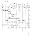
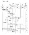
- FIGS. 7-10The operation of an advantageous embodiment of the present invention is illustrated in greater detail in FIGS. 7-10.
- the top row of boxes illustrated in each of the figuresrepresents the functional elements of an advantageous embodiment of the present invention.
- the vertical axis in FIGS. 7-10represents time and the horizontal arrows in each figure represent communications between the functional elements.
- network interface 160offers/routes a call to both wired station 150 and either mobile station 170 or 175 so that both stations ring concurrently, and the mobile station 170 or 175 answers first.
- switch 140is a PBX
- wired station 150is a telephone associated with the PBX
- mobile station 170 , 175is a cellular telephone. It is understood, however, that switch 140 could similarly be an end office (or a known equivalent thereof) associated with PSTN 110 and wired station 150 could be a telephone capable of accessing PSTN 110 .
- Switch 140is programmed to offer/route the call to interface switch 161 to permit network interface 160 to act as point of control of the call.
- Controller 165 of network interface 160determines through SDB 167 whether the call is for a subscriber of the service by comparing the dialed number (e.g., MIN, CPID, etc.) to numbers stored in SDB 167 corresponding to subscribers (Step a).
- dialed numbere.g., MIN, CPID, etc.
- network interface 160effectively instructs switch 140 to process the call in a conventional manner by delivering the call back to switch 140 or taking other suitable action such as playing an announcement.
- controller 165looks up and retrieves the MIN and/or route-to-extension for the particular subscriber stored in SDB 167 .
- Network interface 160utilizes the retrieved MIN for the particular subscriber to interact with VLR 168 to determine whether the subscriber is registered in the applicable coverage area (Step b). As discussed above, controller 165 determines through VLR 168 whether the subscriber is registered in the applicable coverage area in a conventional manner.
- network interface 160pages mobile station 170 or 175 , preferably in a manner compatible with the specifications provided in Telecommunications Industry Association TIA-EIA Interim Standard IS-136.1 rev. A and IS-136.2 rev. A, entitled “Dual-Mode Mobile Station Base Station Compatibility Standard” (IS-136), which is incorporated herein by reference (Step c).
- the pagemay be accomplished in the private cellular domain through base unit 162 or eventually in the public cellular domain through MSC 135 and base station 136 .
- controller 165 of network interface 160starts the following timers, which are preferably programmed into controller 165 :
- controller 165cancels the T(P 1 S) timer, preferably causes mobile station 170 or 175 to become active on a Digital Traffic Channel (preferably in a manner compatible with the specifications provided in IS-136), and instructs mobile station 170 or 175 to alert the subscriber by ringing mobile station 170 or 175 (Step d).
- a mobile station ring initiating time T 1elapses between paging mobile station 170 or 175 and actually ringing mobile station 170 or 175 (Steps c-d).
- Mobile station ring initiating time T 1is a delay that is inherent in conventional wireless networks.
- controller 165starts timer T(A 1 S), which is also preferably programmed into controller 165 .
- the expiration of timer T(A 1 S)denotes an alerting time-out to ensure that the mobile station 170 or 175 does not ring forever.
- controller 165Upon the expiration of timer T(RB 1 S), controller 165 instructs network interface 160 to provide an audible ringback to the calling party at station 120 (Step e).
- timer T(CR 1 )Upon the expiration of timer T(CR 1 ), controller 165 instructs network interface 160 to offer/route the call to the switch 140 , which switch 140 will then alert the subscriber by ringing wired station 150 (Step f).
- Timer T(CR 1 )is set for a period of time estimated to be equivalent to mobile station ring initiating time T 1 .
- the delay provided by timer T(CR 1 ) in offering/routing the call to wired station 150therefore, permits wired station 150 and mobile station 170 or 175 to ring concurrently by taking into account mobile station ring initiating time T 1 , which is inherent in conventional wireless networks.
- network interface 160cancels timer T(A 1 S), propagates answer supervision toward the calling party at originating station 120 , and invokes call release procedures on the outgoing leg of switch 140 to wired station 150 (Step g). Finally, network interface 160 removes the audible ringback and establishes a voice path between mobile station 170 or 175 and originating station 120 (Step h). When either party (calling party or subscriber) terminates the call by hanging up their respective station, all resources are released by the network interface 160 .
- the subscriberanswers the wired station 150 rather than the mobile station 170 , 175 .
- steps a-fare identical to that described above with respect to FIG. 7 .
- network interface 160terminates the audible ringback provided to the calling party, propagates answer supervision toward the inbound call leg of switch 140 (toward station 120 ), and cuts through a two-way voice path between the two call legs of switch 140 (Step g 1 ).
- network interface 160invokes call release procedures (preferably in a manner that is compatible with the procedures outlined in IS-136) to release the mobile station 170 or 175 leg of the call (Step h 1 ).
- FIG. 9illustrates the circumstance where network interface 160 does not receive a page-response from mobile station 170 or 175 .
- steps a-care identical to that described above with respect to FIG. 7 .
- network interface 160does not receive a page-response from mobile station 170 or 175
- network interface 160times out on a page-response timer T(P 1 S) from mobile station 170 , 175 and abandons the call delivery attempt to mobile station 170 , 175 .
- network interface 160cancels the page and other call delivery procedures to mobile station 170 , 175 , cancels all outstanding timers, and offers the call to switch 140 , which in turn alerts wired station 150 (Step d 1 ).
- network interface 160cuts through the voice path between the incoming leg (from station 120 ) and outgoing leg (to station 150 ) of switch 140 (Step e 1 ) and, thereafter, preferably receives answer supervision from switch 140 (which is propagated back to the calling party) (Step f 1 ).
- network element 160should network element 160 not receive a answer indication from mobile station 170 or 175 or wired station 150 within a specified period after alerting mobile station 170 or 175 , then network element 160 times out on mobile station 170 or 175 .
- steps a-fare identical to that described above with respect to FIGS. 7 and 8.
- network element 160upon the expiration of timer T(A 1 S), invokes call release procedures (preferably in a manner that is compatible with the procedures outlined in IS-136) to release the mobile station 170 , 175 leg of the call (Step h 2 ).
- network interface 160terminates the audible ringback provided to the calling party, propagates answer supervision toward the inbound call leg of switch 140 (toward station 120 ), and cuts through a two-way voice path between the two call legs of switch 140 (Step g 2 ).
- timers T(P 1 S), T(CR 1 ), T(RB 1 S) and T(A 1 S)are intended to be adjustable depending upon the particular application provided by the service provider, Table I below enumerates a preferred default setting for each of the above-mentioned timers:
- the present inventionmay also be utilized in a single telecommunications network to concurrently ring multiple stations within that network. It is also understood that the present invention may be utilized to concurrently ring a plurality of wired stations served by one or more wired telecommunications networks or to concurrently ring a plurality of mobile stations served by one or more wireless telecommunications networks.
Landscapes
- Engineering & Computer Science (AREA)
- Computer Networks & Wireless Communication (AREA)
- Signal Processing (AREA)
- Mobile Radio Communication Systems (AREA)
- Telephonic Communication Services (AREA)
- Sub-Exchange Stations And Push- Button Telephones (AREA)
Abstract
Description
| TABLE I | ||
| DEFAULT VALUE | ||
| TIMER | DESCRIPTION | (SECONDS) |
| T(CR1) | Concurrent ring timer in instances when subscriber is | 10 |
| registered in the coverage area of network interface | ||
| element 160 | ||
| T(CR1) | Concurrent ring timer in instances when subscriber is | 12 |
| not registered in the coverage area of network interface | ||
| element 160 | ||
| T(RB1S) | Ringback timer in instances when subscriber is | 6 |
| registered in the coverage area of network interface | ||
| element 160 | ||
| T(RB1S) | Ringback timer in instances when subscriber is not | 8 |
| registered in the coverage area of network interface | ||
| element 160 | ||
| T(P1S) | Paging timer in instances where network interface | 8 |
| registered in the coverage area of network interface | ||
| element 160 | ||
| T(P1S) | Paging timer in instances where network interface | 8 |
| registered in the coverage area of network interface | ||
| element 160 | ||
| T(A1S) | Alerting timer in instances where network interface | 24 |
| public user registered in the coverage area of network | ||
| interface element 160 | ||
| T(A1S) | Alerting timer in instances where network interface | 30 |
| registered outside the coverage area of | ||
| interface | ||
| 160 | ||
Claims (31)
Priority Applications (1)
| Application Number | Priority Date | Filing Date | Title |
|---|---|---|---|
| US10/123,466US6584317B2 (en) | 1996-06-27 | 2002-04-15 | Concurrent ringing on multiple network telephones |
Applications Claiming Priority (2)
| Application Number | Priority Date | Filing Date | Title |
|---|---|---|---|
| US08/669,805US6405041B1 (en) | 1996-06-27 | 1996-06-27 | Concurrent ringing on multiple network telephones |
| US10/123,466US6584317B2 (en) | 1996-06-27 | 2002-04-15 | Concurrent ringing on multiple network telephones |
Related Parent Applications (1)
| Application Number | Title | Priority Date | Filing Date |
|---|---|---|---|
| US08/669,805ContinuationUS6405041B1 (en) | 1996-06-27 | 1996-06-27 | Concurrent ringing on multiple network telephones |
Publications (2)
| Publication Number | Publication Date |
|---|---|
| US20020160780A1 US20020160780A1 (en) | 2002-10-31 |
| US6584317B2true US6584317B2 (en) | 2003-06-24 |
Family
ID=24687817
Family Applications (2)
| Application Number | Title | Priority Date | Filing Date |
|---|---|---|---|
| US08/669,805Expired - LifetimeUS6405041B1 (en) | 1996-06-27 | 1996-06-27 | Concurrent ringing on multiple network telephones |
| US10/123,466Expired - Fee RelatedUS6584317B2 (en) | 1996-06-27 | 2002-04-15 | Concurrent ringing on multiple network telephones |
Family Applications Before (1)
| Application Number | Title | Priority Date | Filing Date |
|---|---|---|---|
| US08/669,805Expired - LifetimeUS6405041B1 (en) | 1996-06-27 | 1996-06-27 | Concurrent ringing on multiple network telephones |
Country Status (3)
| Country | Link |
|---|---|
| US (2) | US6405041B1 (en) |
| TW (1) | TW353256B (en) |
| WO (1) | WO1997050234A2 (en) |
Cited By (9)
| Publication number | Priority date | Publication date | Assignee | Title |
|---|---|---|---|---|
| US20050190789A1 (en)* | 1999-02-05 | 2005-09-01 | Jay Salkini | Multi-protocol wireless communication apparatus and method |
| US20060104430A1 (en)* | 2004-11-12 | 2006-05-18 | International Business Machines Corporation | Method for multiple dialing by phone |
| US20070165833A1 (en)* | 2006-01-12 | 2007-07-19 | Sbc Knowledge Ventures L.P. | Apparatus and method for finding a called party over a telecommunication network |
| US20070201445A1 (en)* | 2006-02-13 | 2007-08-30 | Qiu Chaoxin Charles | Methods and apparatus to limit ring trees in voice over internet protocol networks |
| US20070211702A1 (en)* | 2006-03-08 | 2007-09-13 | Doradla Anil K | Methods and apparatus to perform parallel ringing across communication networks |
| USRE42271E1 (en) | 2003-09-23 | 2011-04-05 | International Business Machines Corporation | Wireless telephone system including voice over IP and POTS |
| US7983148B1 (en) | 2004-07-12 | 2011-07-19 | Avaya Inc. | Disaster recovery via alternative terminals and partitioned networks |
| US20150003437A1 (en)* | 2002-08-22 | 2015-01-01 | At&T Mobility Ii Llc | LAN Based Wireless Communications System |
| US9438728B2 (en) | 2014-10-27 | 2016-09-06 | Mya Number Corp. | Telephone number grouping service for telephone service providers |
Families Citing this family (29)
| Publication number | Priority date | Publication date | Assignee | Title |
|---|---|---|---|---|
| US6009159A (en)* | 1998-06-15 | 1999-12-28 | Lucent Technologies Inc. | Apparatus, method and system for controlling the start of alerting of multiple leg telecommunication sessions |
| DE19829342A1 (en)* | 1998-07-01 | 2000-01-05 | Alcatel Sa | Parallel call delivery on several TK network accesses |
| DE69942735D1 (en) | 1998-12-10 | 2010-10-21 | Lucent Technologies Inc | PABX management |
| EP1009172B1 (en)* | 1998-12-10 | 2010-09-08 | Lucent Technologies Inc. | Management of a PABX |
| EP1011253B1 (en)* | 1998-12-17 | 2004-03-24 | Siemens Aktiengesellschaft | Method for establishing a call to a usergroup in a telecommunications network |
| KR20000042230A (en)* | 1998-12-24 | 2000-07-15 | 윤종용 | Method for multiplexly executing call forwarding process in private exchange system |
| US7292858B2 (en) | 1999-06-14 | 2007-11-06 | Ascendent Telecommunications, Inc. | Method and apparatus for communicating with one of plural devices associated with a single telephone number during a disaster and disaster recovery |
| ES2684505T3 (en) | 1999-06-14 | 2018-10-03 | Blackberry Corporation | Method and apparatus for communicating through virtual office telephone extensions |
| US7162020B1 (en)* | 1999-06-14 | 2007-01-09 | Ascendent Telecommunications, Inc. | Method and apparatus for selectively establishing communication with one of plural devices associated with a single telephone number |
| AU7374500A (en)* | 1999-09-22 | 2001-04-24 | Excel Switching Corporation | Simultaneous ringing and dispatch emulation in an integrated wireless/wireline telecommunication system |
| EP1238524B9 (en)* | 1999-12-17 | 2009-09-09 | Nokia Siemens Networks Gmbh & Co. Kg | Method for signaling an incoming call |
| US6975874B1 (en)* | 2000-06-09 | 2005-12-13 | International Business Machines Corporation | Portable phone that changes function according to its self-detected geographical position |
| US7130643B2 (en)* | 2001-01-12 | 2006-10-31 | International Business Machines Corporation | Method and system for selectively paging a communication device based on self-detected position of the communication device |
| US6633767B2 (en)* | 2001-05-07 | 2003-10-14 | Winphoria Networks, Inc. | System and method of managing interconnections in mobile communications |
| ATE313918T1 (en)* | 2002-06-28 | 2006-01-15 | T Mobile Deutschland Gmbh | METHOD AND ARRANGEMENT FOR TREATING SHORT MESSAGES WITH TELEPHONE NUMBER PORTABILITY |
| US7388854B2 (en)* | 2003-02-12 | 2008-06-17 | Samsung Electronics Co., Ltd. | System for interconnecting wired and wireless phone services and method for processing call |
| US7228145B2 (en)* | 2003-05-21 | 2007-06-05 | Avaya Technology Corp. | Dropped call continuation |
| US8457082B2 (en) | 2003-06-06 | 2013-06-04 | At&T Intellectual Property I, L.P. | System and method for providing integrated voice and data services utilizing wired cordless access with unlicensed/unregulated spectrum |
| US7627338B2 (en)* | 2003-06-06 | 2009-12-01 | At&T Intellectual Property I, L.P. | System and method for providing integrated voice and data services utilizing wired cordless access with unlicensed spectrum and wired access with licensed spectrum |
| US7657270B2 (en)* | 2003-06-06 | 2010-02-02 | At&T Intellectual Property I, L.P. | System and method for providing a single telephone number for use with a plurality of telephone handsets |
| US7646777B2 (en) | 2003-07-07 | 2010-01-12 | At&T Intellectual Property I, L.P. | Communication environment switchover |
| US7656860B2 (en)* | 2003-07-22 | 2010-02-02 | Phillips Bruce A | Personal communication service network interface device |
| CN100521713C (en)* | 2003-12-11 | 2009-07-29 | 上海贝尔阿尔卡特股份有限公司 | Device and method of realizing multiple ringing sevices |
| US7277735B1 (en)* | 2004-04-22 | 2007-10-02 | Sprint Spectrum L.P. | Method and system for invoking simultaneous ringing |
| US8879707B2 (en)* | 2005-01-14 | 2014-11-04 | Avaya Inc. | Private branch exchange that manages interactions between associated telecommunications terminals |
| CN100550939C (en)* | 2005-07-29 | 2009-10-14 | 中兴通讯股份有限公司 | A kind of method that in communication system, realizes double ringing service |
| US8224307B2 (en) | 2006-10-06 | 2012-07-17 | Embarq Holdings Company, Llc | System and method for transferring telephone calls between mobile and cordless modes |
| DE102007011886A1 (en)* | 2007-03-13 | 2008-09-18 | Detecon International Gmbh | Method and device for the production of fixed-mobile-convergent telecommunication services |
| CN101677435B (en) | 2008-09-17 | 2013-04-24 | 华为技术有限公司 | Method and device for realizing service of one number on two phones |
Citations (10)
| Publication number | Priority date | Publication date | Assignee | Title |
|---|---|---|---|---|
| US5103448A (en) | 1989-03-31 | 1992-04-07 | Gec Plessey Telecommunications Ltd. | Simultaneous ringing control in the time division duplex telecommunications system |
| US5127042A (en) | 1988-09-23 | 1992-06-30 | Motorola, Inc. | Cellular cordless telephone |
| EP0549126A2 (en) | 1991-12-23 | 1993-06-30 | AT&T Corp. | Method and apparatus for alerting multiple telephones for an incoming call |
| US5454032A (en) | 1993-01-29 | 1995-09-26 | Mitel Corporation | Method of establishing communication link to one of multiple devices associated with single telephone number |
| US5502757A (en) | 1993-12-22 | 1996-03-26 | At&T Corp. | Location dependent service for a wireless telephone |
| US5502762A (en) | 1994-06-10 | 1996-03-26 | Andrew; Brian J. | System and method for simultaneously controlling ringing at local and remote telephones |
| GB2293521A (en) | 1994-09-21 | 1996-03-27 | Mitel Corp | Delayed seizure on associated devices |
| US5548636A (en) | 1993-06-11 | 1996-08-20 | Northern Telecom Limited | Method and apparatus for providing user controlled call management services |
| US5802160A (en) | 1996-01-19 | 1998-09-01 | Pilgrim Telephone, Inc. | Multi-ring telephone method and system |
| US5956631A (en) | 1993-12-30 | 1999-09-21 | Lucent Technologies, Inc. | Multiple terminal device ringing digital subscriber ISDN terminal |
- 1996
- 1996-06-27USUS08/669,805patent/US6405041B1/ennot_activeExpired - Lifetime
- 1997
- 1997-05-30WOPCT/US1997/009497patent/WO1997050234A2/enactiveApplication Filing
- 1997-06-24TWTW086108830Apatent/TW353256B/ennot_activeIP Right Cessation
- 2002
- 2002-04-15USUS10/123,466patent/US6584317B2/ennot_activeExpired - Fee Related
Patent Citations (10)
| Publication number | Priority date | Publication date | Assignee | Title |
|---|---|---|---|---|
| US5127042A (en) | 1988-09-23 | 1992-06-30 | Motorola, Inc. | Cellular cordless telephone |
| US5103448A (en) | 1989-03-31 | 1992-04-07 | Gec Plessey Telecommunications Ltd. | Simultaneous ringing control in the time division duplex telecommunications system |
| EP0549126A2 (en) | 1991-12-23 | 1993-06-30 | AT&T Corp. | Method and apparatus for alerting multiple telephones for an incoming call |
| US5454032A (en) | 1993-01-29 | 1995-09-26 | Mitel Corporation | Method of establishing communication link to one of multiple devices associated with single telephone number |
| US5548636A (en) | 1993-06-11 | 1996-08-20 | Northern Telecom Limited | Method and apparatus for providing user controlled call management services |
| US5502757A (en) | 1993-12-22 | 1996-03-26 | At&T Corp. | Location dependent service for a wireless telephone |
| US5956631A (en) | 1993-12-30 | 1999-09-21 | Lucent Technologies, Inc. | Multiple terminal device ringing digital subscriber ISDN terminal |
| US5502762A (en) | 1994-06-10 | 1996-03-26 | Andrew; Brian J. | System and method for simultaneously controlling ringing at local and remote telephones |
| GB2293521A (en) | 1994-09-21 | 1996-03-27 | Mitel Corp | Delayed seizure on associated devices |
| US5802160A (en) | 1996-01-19 | 1998-09-01 | Pilgrim Telephone, Inc. | Multi-ring telephone method and system |
Non-Patent Citations (3)
| Title |
|---|
| Comcast Connections, Issue 7, vol. 6, Summer 1996, Section entitled "Direct Link, One Number Service to Launch in Sep." |
| Communications Daily, Nov. 20, 1992. |
| U.S. Patent Application Ser. No. 08/175,659, filed Dec. 30, 1993, "Multiple Terminal Device Ringing in Telephone Communications Systems." |
Cited By (14)
| Publication number | Priority date | Publication date | Assignee | Title |
|---|---|---|---|---|
| US20050190789A1 (en)* | 1999-02-05 | 2005-09-01 | Jay Salkini | Multi-protocol wireless communication apparatus and method |
| US7733901B2 (en)* | 1999-02-05 | 2010-06-08 | Tecore | Multi-protocol wireless communication apparatus and method |
| US20150003437A1 (en)* | 2002-08-22 | 2015-01-01 | At&T Mobility Ii Llc | LAN Based Wireless Communications System |
| US9930605B2 (en)* | 2002-08-22 | 2018-03-27 | At&T Mobility Ii Llc | LAN based wireless communications system |
| US9629062B2 (en)* | 2002-08-22 | 2017-04-18 | At&T Mobility Ii Llc | LAN based wireless communications system |
| USRE42271E1 (en) | 2003-09-23 | 2011-04-05 | International Business Machines Corporation | Wireless telephone system including voice over IP and POTS |
| US7983148B1 (en) | 2004-07-12 | 2011-07-19 | Avaya Inc. | Disaster recovery via alternative terminals and partitioned networks |
| US20060104430A1 (en)* | 2004-11-12 | 2006-05-18 | International Business Machines Corporation | Method for multiple dialing by phone |
| US20070165833A1 (en)* | 2006-01-12 | 2007-07-19 | Sbc Knowledge Ventures L.P. | Apparatus and method for finding a called party over a telecommunication network |
| US7881455B2 (en)* | 2006-01-12 | 2011-02-01 | At&T Intellectual Property I, L.P. | Apparatus and method for finding a called party over a telecommunication network |
| US20070201445A1 (en)* | 2006-02-13 | 2007-08-30 | Qiu Chaoxin Charles | Methods and apparatus to limit ring trees in voice over internet protocol networks |
| US7991139B2 (en) | 2006-02-13 | 2011-08-02 | At&T Intellectual Property I, L.P. | Methods and apparatus to limit ring trees in voice over internet protocol networks |
| US20070211702A1 (en)* | 2006-03-08 | 2007-09-13 | Doradla Anil K | Methods and apparatus to perform parallel ringing across communication networks |
| US9438728B2 (en) | 2014-10-27 | 2016-09-06 | Mya Number Corp. | Telephone number grouping service for telephone service providers |
Also Published As
| Publication number | Publication date |
|---|---|
| TW353256B (en) | 1999-02-21 |
| US20020160780A1 (en) | 2002-10-31 |
| WO1997050234A2 (en) | 1997-12-31 |
| WO1997050234A3 (en) | 1998-02-05 |
| US6405041B1 (en) | 2002-06-11 |
Similar Documents
| Publication | Publication Date | Title |
|---|---|---|
| US6584317B2 (en) | Concurrent ringing on multiple network telephones | |
| EP0950329B1 (en) | Method and arrangement for using a mobile phone in a wireless office network | |
| US6073029A (en) | Method and system for providing wireless communications to a subscriber of a private wireline network | |
| US6014377A (en) | System and method for an integrated wireline/wireless service using private branch exchange lines | |
| KR100445295B1 (en) | A mobile communication network having an integrated wireless office system | |
| US5579379A (en) | Personal communications service having a calling party pays capability | |
| US5901359A (en) | System and method for a wireline-wireless network interface | |
| US6535730B1 (en) | Wireless centrex conference call adding a party | |
| US6574470B1 (en) | Programmable ring-call forwarding in a wireless centrex services system | |
| EP1350370A1 (en) | Circuit switched cellulat network to internet calling | |
| US6256512B1 (en) | Mobile access to a PBX via a TLDN | |
| WO1998052337A1 (en) | Method and apparatus for monitoring of telephone calls | |
| US8526590B2 (en) | Distinctive call waiting based on a redirecting number | |
| US6070080A (en) | Called party availability announcement in a radio telecommunications network | |
| US20010041553A1 (en) | Systems and methods for providing intelligent wireless access systems | |
| EP0966142B1 (en) | Apparatus method and system for controlling secondary treatment by a distant switch for multiple leg telecommunication sessions | |
| EP1110421A1 (en) | Home zone extension phone service | |
| KR100285328B1 (en) | Transfer method in mobile communication system | |
| JPH0723440A (en) | Mobile subsctiber connection system | |
| KR20010053765A (en) | The call transfer service method for personal hunting in land and mobile networks | |
| KR20040072388A (en) | Vms service method using map protocol in umts |
Legal Events
| Date | Code | Title | Description |
|---|---|---|---|
| FEPP | Fee payment procedure | Free format text:PAYOR NUMBER ASSIGNED (ORIGINAL EVENT CODE: ASPN); ENTITY STATUS OF PATENT OWNER: LARGE ENTITY | |
| AS | Assignment | Owner name:CINGULAR WIRLEESS II, LLC, GEORGIA Free format text:CERTIFICATE OF CONVERSION;ASSIGNOR:CINGULAR WIRELESS II, INC.;REEL/FRAME:017546/0612 Effective date:20041027 Owner name:CINGULAR WIRLEESS II, LLC,GEORGIA Free format text:ASSIGNMENT OF ASSIGNORS INTEREST;ASSIGNOR:CINGULAR WIRELESS II, INC.;REEL/FRAME:017546/0612 Effective date:20041027 Owner name:CINGULAR WIRELESS II, INC.,GEORGIA Free format text:ASSIGNMENT OF ASSIGNORS INTEREST;ASSIGNOR:NEW CINGULAR WIRELESS SERVICES, INC. F/K/A AT&T WIRELESS SERVICES, INC.;REEL/FRAME:017555/0711 Effective date:20041027 Owner name:CINGULAR WIRLEESS II, LLC, GEORGIA Free format text:ASSIGNMENT OF ASSIGNORS INTEREST;ASSIGNOR:CINGULAR WIRELESS II, INC.;REEL/FRAME:017546/0612 Effective date:20041027 Owner name:CINGULAR WIRELESS II, INC., GEORGIA Free format text:ASSIGNMENT OF ASSIGNORS INTEREST;ASSIGNOR:NEW CINGULAR WIRELESS SERVICES, INC. F/K/A AT&T WIRELESS SERVICES, INC.;REEL/FRAME:017555/0711 Effective date:20041027 | |
| AS | Assignment | Owner name:CINGULAR WIRELESS II, LLC,GEORGIA Free format text:CERTIFICATE OF CONVERSION;ASSIGNOR:CINGULAR WIRELESS II, INC.;REEL/FRAME:017696/0375 Effective date:20041027 Owner name:CINGULAR WIRELESS II, LLC, GEORGIA Free format text:CERTIFICATE OF CONVERSION;ASSIGNOR:CINGULAR WIRELESS II, INC.;REEL/FRAME:017696/0375 Effective date:20041027 | |
| FPAY | Fee payment | Year of fee payment:4 | |
| AS | Assignment | Owner name:AT&T MOBILITY II, LLC, GEORGIA Free format text:CHANGE OF NAME;ASSIGNOR:CINGULAR WIRELESS II, LLC;REEL/FRAME:020873/0306 Effective date:20070420 | |
| AS | Assignment | Owner name:AT&T MOBILITY II LLC, GEORGIA Free format text:CHANGE OF NAME;ASSIGNOR:AT&T MOBILITY II, LLC;REEL/FRAME:020936/0603 Effective date:20070830 | |
| FPAY | Fee payment | Year of fee payment:8 | |
| REMI | Maintenance fee reminder mailed | ||
| LAPS | Lapse for failure to pay maintenance fees | ||
| LAPS | Lapse for failure to pay maintenance fees | Free format text:PATENT EXPIRED FOR FAILURE TO PAY MAINTENANCE FEES (ORIGINAL EVENT CODE: EXP.) | |
| FP | Lapsed due to failure to pay maintenance fee | Effective date:20150624 | |
| STCH | Information on status: patent discontinuation | Free format text:PATENT EXPIRED DUE TO NONPAYMENT OF MAINTENANCE FEES UNDER 37 CFR 1.362 |